

Page 1
J
•
•
•
:e
•
•
•
•
•
•
•
•
•
•
•
•
•
•
•
:e
•
•
•
•
•
•
•
•
•
•
•
•
•
•
•
:e
•
•
•
~
@
Cybex 900T Treadmill Service Manual
Cardiovascular Systems
Cybex and the Cybex logo are registered trademarksofCybex International, Inc. Bioflex and the Bioflex logo are registered
trademarks of Cybex International, Inc. Polar is a registered trademarkofPolar.
DISCLAIMER:
Cybex International, Inc.
makesnorepresentationsorwarranties
regarding
the
contentsofthis
manual. We
reserve
the
righttorevise
this
documentatany
timeorto
make
changestothe
product
described
within
it
without
notice
or
obligationtonotify
any
person
of
such
revisionsorchanges.
© 2001, Cybex International, Inc. All rights reserved. Printed
in
United StatesofAmerica.
10 Trotter Drive Medway, MA
02053·
888-GO-CYBEX·
888-462-9239·
508-533-4300·
FAX
508-533-5183
www.eCybex.com.techhelp@cybexintl.com.techpubs@cybexintl.com • SM-16106 Rev A • June 2001
Page 2

~
•
•
•
e:
•
•
•
•
•
•
•
•
•
•
•
•
•
•
•
e:
•
•
•
•
•
•
•
•
•
•
•
•
•
•
•
e:
•
•
•
Page 3
•
•
•
•
:e
•
•
•
•
•
•
•
•
•
•
•
•
•
•
•
:e
•
•
•
•
•
•
•
•
•
•
•
•
•
•
•
:e
•
•
•
Cybex
900T
Treadmill
Service
Manual
About
This Manual
For your convenience, all measurements and voltage requirements are listed in both English
and metric units. English values are listed first, followed by metric units in parentheses. For
example:
1"
(2.54 em).
The 900T Treadmill is a newer model that has replaced the former 685 model. This manual,
part number SM-16106, should be referred
to
for
685 service questions. An Owner's Manual
is shipped with each 900T Treadmill.
To
purchase a copyofany manual, order online at
www.eCybex.com, fax your order
to
508-533-5383 or contact Cybex Customer Service at
888-462-9239 or 508-533-4300.
To
contact Cybex with comments about this manual you may send email
to
techpubs@cybexintl.com.
FCC
Compliance
Information
! WARNING: Changesormodifications to this unit
not
expressly
approvedbythe party
responsible for compliance
could
void the user's authority to operate
the equipment.
This equipment has been tested and foundtocomply with the limits
for
a Class A digital
device, pursuant
to
Part 15ofthe FCC Rules. Operation is subjecttothe following
two
conditions:
(1)
This device may not cause hannful interference, and
(2)
this device must
accept any interference received, including interference that may cause undesired operation.
Pagei
Page 4

Pageii
Cybex 900T Treadmill
Service
Manual
•
•
•
•
e:
•
•
•
•
•
•
•
•
•
•
•
•
•
•
•
-:
•
•
•
•
•
•
•
•
•
•
•
•
•
•
•
e:
•
•
•
Page 5
Cybex 900T Treadmill Service Manual
Table of Contents
•
•
•
•
:e
•
•
•
•
•
•
•
•
•
•
•
•
•
•
•
:e
•
•
•
•
•
•
•
•
•
•
•
•
•
•
•
:e
•
•
•
Front Pages
About
this Manual i
FCC Compliance Information
i
TableofContents .iii
1 Safety
Important Voltage Information 1-1
Grounding Instructions 1-1
Important Safety Instructions 1-2
Caution Decals
1-4
2 Technical Specifications
Specifications 2-1
Bioflex 2-2
3 Preventive Maintenance
Regular Maintenance Activities 3-1
Cleaning Your Treadmill 3-1
Running Belt Maintenance
3-2
Other Preventive Maintenance
3-6
Service Schedule
3-7
Log Sheet
3-8
4 Troubleshooting
Diagnostic Test
Mode
4-1
Diagnostic Menu 4-1
LED Functions
4-6
Motor
Current & Voltage
4-7
Speed Sensor Adjustment
4-9
Error Codes 4-10
Flow Charts 4-13
5 Removal & Replacement
Running Belt & Deck 5-1
Drive Belt
5-4
Front Roller
5-4
Rear Roller
5-4
Drive
Motor
5-5
Drive
Motor
Cleaning
5-8
Motor
Brushes 5-12
Elevation
Motor
5-14
Limit Switch Assembly 5-17
PWM Module 5-18
Display Board
5-20
EPROM 5-21
Contact Heart Rate Board 5-22
CSAFE Board 5-24
Display Cable 5-25
Display Overlays 5-26
Handrail Assembly 5-28
6 Diagrams
Parts List 6-1
Exploded View
6-3
900T Schematic
6-4
7 Customer Service
Contacting Service 7-1
Serial
Number
7-1
Retum Material Authorization (RMA)
..
7-1
Damaged Parts 7-2
Page
iii
Page 6

Cybex 900T Treadmill Service
Manual
•
•
•
•
-:
•
•
•
•
•
•
•
•
•
•
•
•
•
•
•
e:
•
•
•
•
•
•
•
•
•
•
•
•
•
•
•
e:
•
•
•
Page 7
Cybex
900T
Treadmill
Service
Manual
IMPORTANT: Read all instructions
and
warnings before using the treadmill.
Important
Voltage
Infonnation
Page
1-1
Front Pages
About this Manual i
FCC Compliance Infoonation
..
i
Table
of
Contents
iii
1
Safety
~
Voltage Information 1-1
Grounding Instructions
.....
1-1
Important SafetyInstructions
1-2
Caution Decals . . . . . . . ...1-4
2
Technical
Specificatiolls
~
2-1
Bioflex
2-2
3 Preventive
Maintenance
Regular
MarnenMCe
Activities
3-1
Cleaning YourTreadmill. .
..
3-1
Running Belt Maintenance . 3-2
Other Preventive
Maintenance
~
Service Schedule 3-7
Log
Sheet
3-8
4
TroubIeshooUlg
Diagnostic Test
Mode
4-1
Diagnostic
Menu
4-1
LED Functions
4-6
Motor
Current & Voltage
4-7
Speed
Sensor
Adjustment..4-9
Error
Codes
4-10
Flow Charts
4-13
5
Removal
& RepIac:ement
Running Belt & Deck 5-1
Drive
Belt 5-4
Front Roller 5-4
Rear
Roller 5-4
Drive
Motor
5-5
Drive
Motor
Cleaning
5-8
Motor
Brushes. . . . . . . ...5-12
Elevation
Motor
5-14
Umit Switch Assembly 5-17
PWM
Module
5-18
Display Board
5-20
EPROM
5-21
Contact Heart
Rate
Board .
5-22
CSAFE
Board
5-24
Display Cable
5-25
Display Overlays
5-26
Handrail Assembly
5-28
6
Diagrams
Parts
Ust
6-1
Exploded
VIeW
6-3
900T Schematic 6-4
7 Customer Service
Contacting Service
7-1
Serial Number
7-1
Return Material Autt1orization
(RMA)
7-1
Damaged
Parts.
. . . . . . ...7-2
This treadmillisfor use on a
nominal 115
VAG
±15%, 60
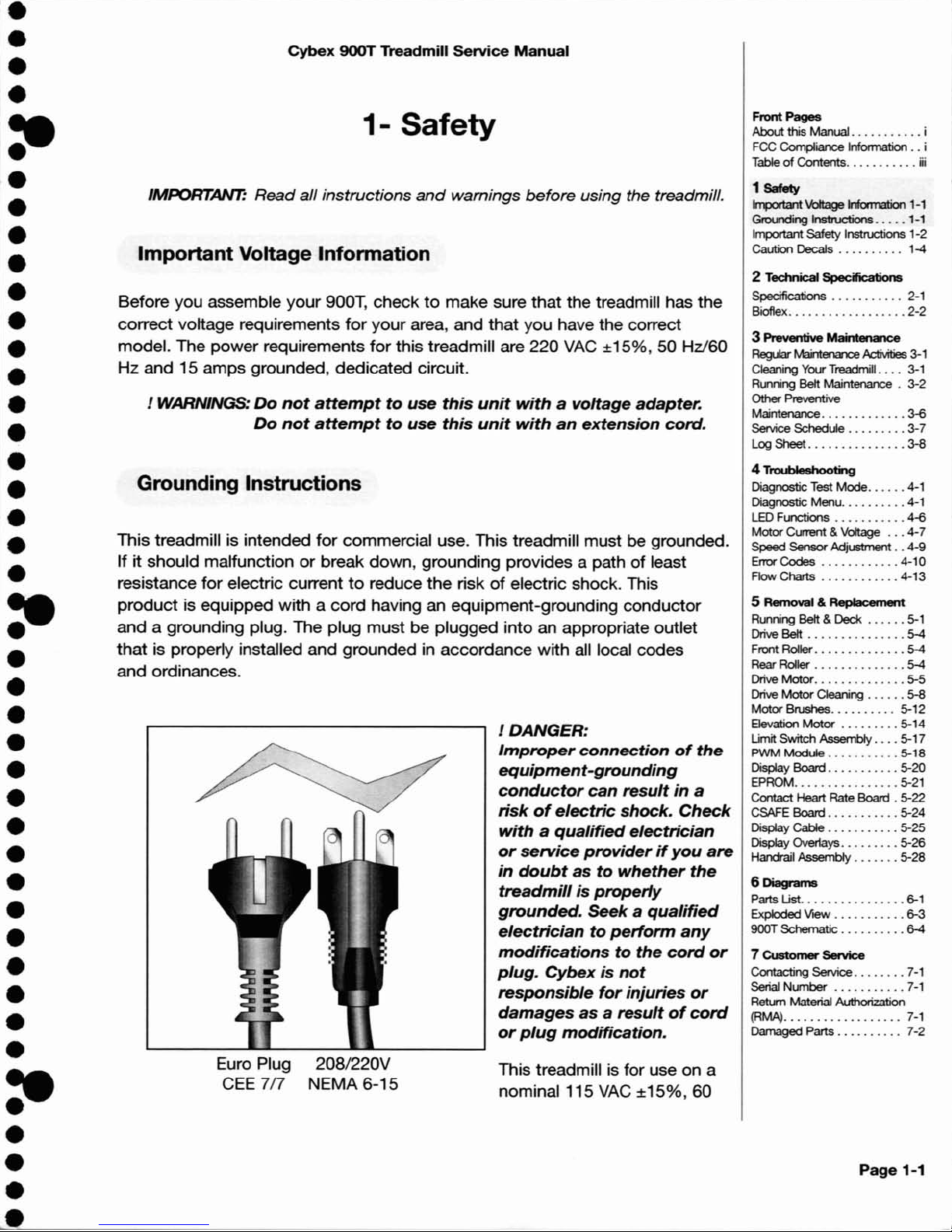
/ DANGER:
Improper
connectionofthe
equipment-grounding
conductor
can
result
in
a
riskofelectric
shock.
Check
withaqualified
electrician
or
service
providerifyou
are
in
doubt
as
to
whether
the
treadmillisproperly
grounded.
Seekaqualified
electriciantoperform
any
modifications
to
the
cord
or
plug.
Cybexisnot
responsible
for
injuries
or
damages
as
a
resultofcord
or
plug
modification.
208/220V
NEMA 6-15
Euro Plug
GEE
7/7
Grounding
Instructions
1-
Safety
Before you assemble your 900T, checktomake sure that the treadmill has the
correct voltage requirements
for
your area, and that you have the correct
model. The power requirements
for
this treadmill are 220
VAG
±15%, 50 Hz/60
Hz and 15 amps grounded, dedicated circuit.
/ WARNINGS:
Do
not
attempt
to
use
this
unit
withavoltage
adapter.
Do
not
attempt
to
use
this
unit
with
an
extension
cord.
This treadmill is intended
for
commercial use. This treadmill must be grounded.
If it should malfunction
or
break down, grounding provides a path of least
resistance for electric current
to
reduce the riskofelectric shock. This
product
is equipped with a cord having an equipment-grounding conductor
and a grounding plug. The plug must be plugged into an appropriate outlet
that
is properly installed and grounded in accordance with all local codes
and ordinances.
•
•
•
•
:e
•
•
•
•
•
•
•
•
•
•
•
•
•
•
•
:e
•
•
•
•
•
•
•
•
•
•
•
•
•
•
•
:e
•
•
•
Page 8
Page
1-2
Cybex 900T Treadmill
service
Manual
Hz
and20ampsora
220
VAC
±15%,
50 Hz/60 Hz and15amps
grounded,
dedicated
circuit.
Make sure
that
the
treadmill is connectedtoan outlet having
the
same
configuration as
the
plug. Do
not
use a
ground
plug adaptertoadapt
the
power
cordtoa
non-grounded
outlet.
Important
Safety
Instructions
(Save These Instructions)
J
DANGER:
To
reduce
the
riskofelectric
shock,
always
unplug
this
treadmill
from
the
electrical
outlet
immediately
after
usingitand
before
cleaning
it.
JWARNING:
Serious
injury
could
occurifthese
precautions
are
not
observed.
To
reduce
the
riskofbums,
fires,
electric
shock,orinjury:
•
Obtain
a medical exam before beginning any exercise program.
• Keep children
away
from the treadmill. Teenagers
and
disabled
persons
must
be
supervised while using.
•
Stop
exercising if you feel faint, dizzy,orexperience pain at any
time
while exercising
and
consult
your
physician.
•
Use
the
treadmill handrails
for
support
andtomaintain balance.
.•
Use
caution when mounting and dismounting
the
treadmill.
•
Disconnect
all
power
before servicing
the
treadmill.
• Use a
dedicated
line when operating
the
treadmill.
•
Connect
the
treadmilltoa properly grounded
outlet
only.
•
Do
not
operate electrically powered treadmills in
damporwet
locations.
• Keep
the
running belt clean and
dry
at all times.
•
Stop
and
place
the
treadmill at 0 degrees incline (level)
after
each
use.
•
Do
not
leave
the
treadmill unattended when
plugged
in and running. After turning
off
the
treadmill,
don't
leave it until it
comestoa
complete
stop
and is level.Todisconnect,
turn
all controlstothe
STOPorOFF position, and
then
remove
the
plug from
the
outlet.
•
Inspect
the
treadmill
for
wornorloose
components
before each use.
Do
not
use until
wornordamaged
parts are replaced.
• Maintain and replace worn parts regularly. Refer
to
"Preventive Maintenance" Section
of
Owner's
Manual.
•
•
•
•
e:
•
•
•
•
•
•
•
•
•
•
•
•
•
•
•
e:
•
•
•
•
•
•
•
•
•
•
•
•
•
•
•
e:
•
•
•
Page 9
•
•
•
•
:e
•
•
•
•
•
•
•
•
•
•
•
•
•
•
•
:e
•
•
•
•
•
•
•
•
•
•
•
•
•
•
•
:e
•
•
•
Cybex 900T Treadmill service Manual
• Do not operate the treadmill if
the
cord is damaged, if
the
treadmill is not
working properly,
or
if the treadmill has been
droppedordamaged. Seek
service from a qualified technician.
• Do
not
place
the
cord near heated surfacesorsharp edges.
• Do
not
use the treadmill outdoors.
• Do
not
operate
the
treadmill aroundorwhere aerosol (spray)orwhere
oxygen products are being used.
• Read
and
understand the Owner's Manual completely before using the
treadmill.
• Read and understand emergency
stop
procedures.
• Read and understand all warnings posted on the treadmill.
• Replace any warning label if damaged, worn
or
illegible.
• Do
not
wear
looseordangling clothing while using
the
treadmill.
• Always wear proper footwear on
or
around exercise equipment.
• Keep all
body
parts, hair, towels, water bottles, and the like free and clear
of
moving parts.
• Set
up
and
operate the treadmillona solid, level surface. Do
not
operate
in recessed areas or on plush carpet.
• Provide
the
following clearances: 39 inches(1m)ateach side, 78 inches
(2m)at
the
back, and enough room
for
safe access and passage at the
front
of
the
treadmill. Be sure
your
treadmill is clearofwalls, equipment,
and
other
hard surfaces.
• Do
not
attempt
repairs, electricalormechanical. Seek trained repair
personnel when servicing. Contact
the
nearest authorized Cybex dealer
or
other
competent
repair service.
• Use
Cybex
factory parts when replacing partsonthe
treadmill.
• Do
not
modify
the
treadmill in any way.
• Do
not
use attachments unless recommended
for
the
treadmill by Cybex.
• Report any malfunctions, damageorrepairstothe
facility.
• Do
not
use the treadmill if you exceed 400 Ibs.
(181
kg). This is
the
rated
maximum
user weight.
Front
Pages
About this Manual i
FCC
Compliance Information..i
Table
of
Contents iii
1
Safety
ImportantVoltage Infoonation 1-1
Grounding
Instructions
.....
1-1
Important Safety Instructions 1-2
Caution Decals . . . . . . . ...1-4
2 Technical Specifications
Specifications . . . . . . . . .
..
2-1
Bioflex
2-2
3 Preventive Maintenance
Regular Maintenance
Activities
3-1
Cleaning
Your
Treadmill. ...3-1
Running
Belt
Maintenance . 3-2
Other
Preventive
Maintenance
3-6
Service Schedule
3-7
Log
Sheet
3-8
4 Troubleshooting
Diagnostic Test
Mode
4-1
Diagnostic
Menu
4-1
LED Functions
4-6
Motor
Current & Voltage
4-7
Speed SensorAdjustment..4-9
Error
Codes
4-10
Flow
Charts
4-13
5 Removal &
Replacement
Running Belt & Deck 5-1
Drive Belt 5-4
Front Roller 5-4
Rear Roller 5-4
Drive
Motor
5-5
Drive
Motor
Cleaning
5-8
Motor
Brushes
5-12
Elevation
Motor
5-14
Umit Switch Assembly
5-17
PWM
Module
5-18
Display Board
5-20
EPROM 5-21
Contact Heart Rate Board .
5-22
CSAFE Board
5-24
Display Cable
5-25
Display Overlays
5-26
Handrail Assembly
5-28
6
Diagrams
Parts
Ust
6-1
Exploded
VieW
6-3
900T
Schematic
6-4
7
Customer
5ervice
Contacting Service 7-1
Serial
Number
7-1
Retum
Material Authorization
(RMA)
7-1
Damaged Parts. . . . . . . .
..
7-2
Page
1-3
Page 10
Page
1-4
Cybex 900T Treadmill service Manual
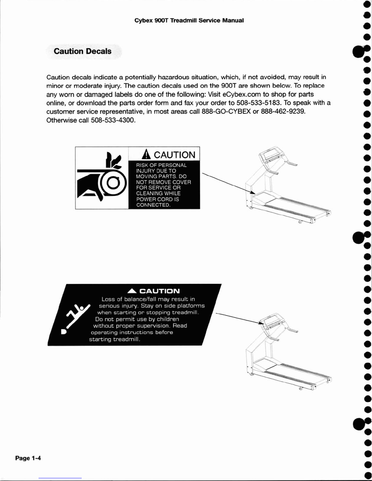
Caution Decals
Caution decals indicate a potentially hazardous situation, which, if
not
avoided, may result
in
minorormoderate injury. The caution decals used on the 900T are shown below.Toreplace
any worn
or
damaged labelsdooneofthe following: Visit eCybex.comtoshop for parts
online, or download the parts order form and fax your order
to
508-533-5183.Tospeak with a
customer service representative, in most areas call 888-GO-CYBEX
or
888-462-9239.
Otherwise call 508-533-4300.
•
•
•
•
-:
•
•
•
•
•
•
•
•
•
•
•
•
•
•
•
-:
•
•
•
•
•
•
•
•
•
•
•
•
•
•
•
-:
•
•
•
Page 11
Cybex 900T Treadmill Service Manual
CAUTION
Page 1-5
Front
Pages
About this Manual i
FCC
Compliance Information
..
i
Table
of
Contents
iii
2
Tecfv1icaI
Spec:ifications
Specifications . . . . . . . . .
..
2-1
Bioflex
2-2
1Safety
I~
Voltage
Information
1-1
Grounding Instructions
.....
1-1
Important Safety Instructions 1-2
Caution Decals . . . . . . . .
..
1-4
3 Preventive Maintenalce
RegUar
Marnencrlc:e
Activities
3-1
Cleaning
Your
Treadmill. ...3-1
Running
Belt Maintenance . 3-2
Other Preventive
Maintenance 3-6
Service Schedule 3-7
Log Sheet 3-8
4
TI"CIWIeehootin
Diagnostic
Test
Mode 4-1
Diagnostic
Menu
4-1
LED
FlI1CIions
4-6
Motor
CUI'1'ent
& Voltage 4-7
Speed
Sensor
Adjustment..4-9
Error
Codes 4-10
Flow Charts 4-13
5 Removal & Replacement
Running
Belt &
Deck
5-1
Drive
Belt
. . . . . . . . . . . . . . . 5-4
Front
Roller 5-4
Rear
Roller
5-4
Drive
Motor 5-5
Drive
MotorCleaning 5-8
Motor Brushes. . . . . . . .
..
5-12
Elevation Motor 5-14
Limit Switch
Assembly
5-17
PWM Module 5-18
Display Board 5-20
EPROM
5-21
Contact Heart
Rate
Board . 5-22
CSAFE
Board 5-24
Display Cable 5-25
Display 0vet1ays 5-26
Handrail Assembly 5-28
6 Diagr.-ns
Parts Ust. . . . . . . . . . . . . ...6-1
Exploded View 6-3
900T Schematic 6-4
7
Customer
Service
Contacting Service
7-1
Serial Number
7-1
Return
Material
Authorization
(RMA)
7-1
Damaged Parts 7-2
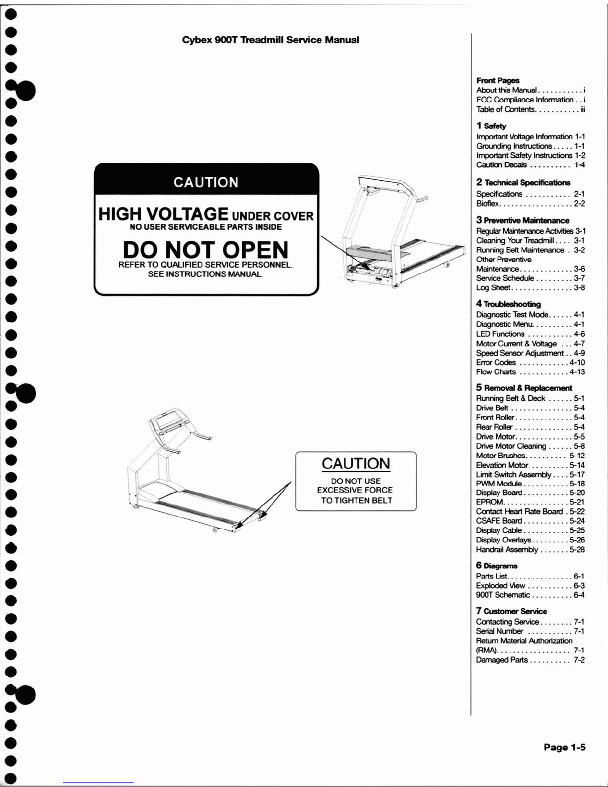
DO
NOT
USE
EXCESSIVE
FORCE
TO
TIGHTEN
BELT
CAUTION
DO NOT OPEN
REFERTOQUALIFIED
SERVICE
PERSONNEl.
SEE
INSTRUCTIONS
MANUAL.
HIGH VOLTAGE UNDER COVER
NO
USER SERVICEABLE PARTS INSIDE
•
•
•
•
:e
•
•
•
•
•
•
•
•
•
•
•
•
•
•
•
:e
•
•
•
•
•
•
•
•
•
•
•
•
•
•
•
:e
•
•
•
>.
Page 12

Page
1-5
Cybex
900T Treadmill
service
Manual
•
•
•
•
e:
•
•
•
•
•
•
•
•
•
•
•
•
•
•
•
-=
•
•
•
•
•
•
•
•
•
•
•
•
•
•
•
e:
•
•
•
Page 13
Cybex
900T
Treadmill
Service
Manual
I
......
E-------
82"
(208
cm)------
...
I
2 - Technical Specifications
2 Technical Specifications
Specifications . . . . . . . . . . . 2-1
Bioflex 2-2
Page
2-1
Front
Pages
About
this Manual i
FCC Compliance Information
..
i
Table
of
Contents iii
1
Safety
Important Voltage Information
1-1
Grounding Instructions
.....
1-1
Important Safety Instructions 1-2
Caution OecaIs . . . . . . . .
..
1-4
3 Preventive
Maintenance
RegUar
Maintenance
Activities
3-1
Cleaning Your Treadmill
....
3-1
Running Belt Maintenance . 3-2
Other
Preventive
Maintenance
3~
Se!vice Schedule 3-7
LogShee1 3-8
4 Troubleshooting
Diagnostic Test
Mode
4-1
Diagnostic Menu
4-1
LED Functions
4~
Motor
Current & Voltage 4-7
Speed
Sensor
Adjustment..4-9
Error
Codes
4-10
Row
Charts 4-13
5
Removal&Replacement
Running Belt &
Deck
5-1
Drive Belt 5-4
Front Roller 5-4
Rear Roller 5-4
Drive
Motor
5-5
Drive
Motor
Cleaning 5-8
Motor
Brushes 5-12
Elevation
Motor
5-14
Umit Switch Assembly 5-17
PWM
Module
5-18
Display Board 5-20
EPROM 5-21
Contact Heart
Rate
Board . 5-22
CSAFE Board 5-24
Display Cable 5-25
Display Over1ays 5-26
Handrail Assembly 5-28
6
Diagrams
Parts Ust
6-1
Exploded
VieW
6-3
900T
Schematic 6-4
7
Customer
Service
Contacting Service
7-1
Serial Number 7-1
Retum
Material Authorization
(RMA)
7-1
Damaged
Parts .... . . . 7-2
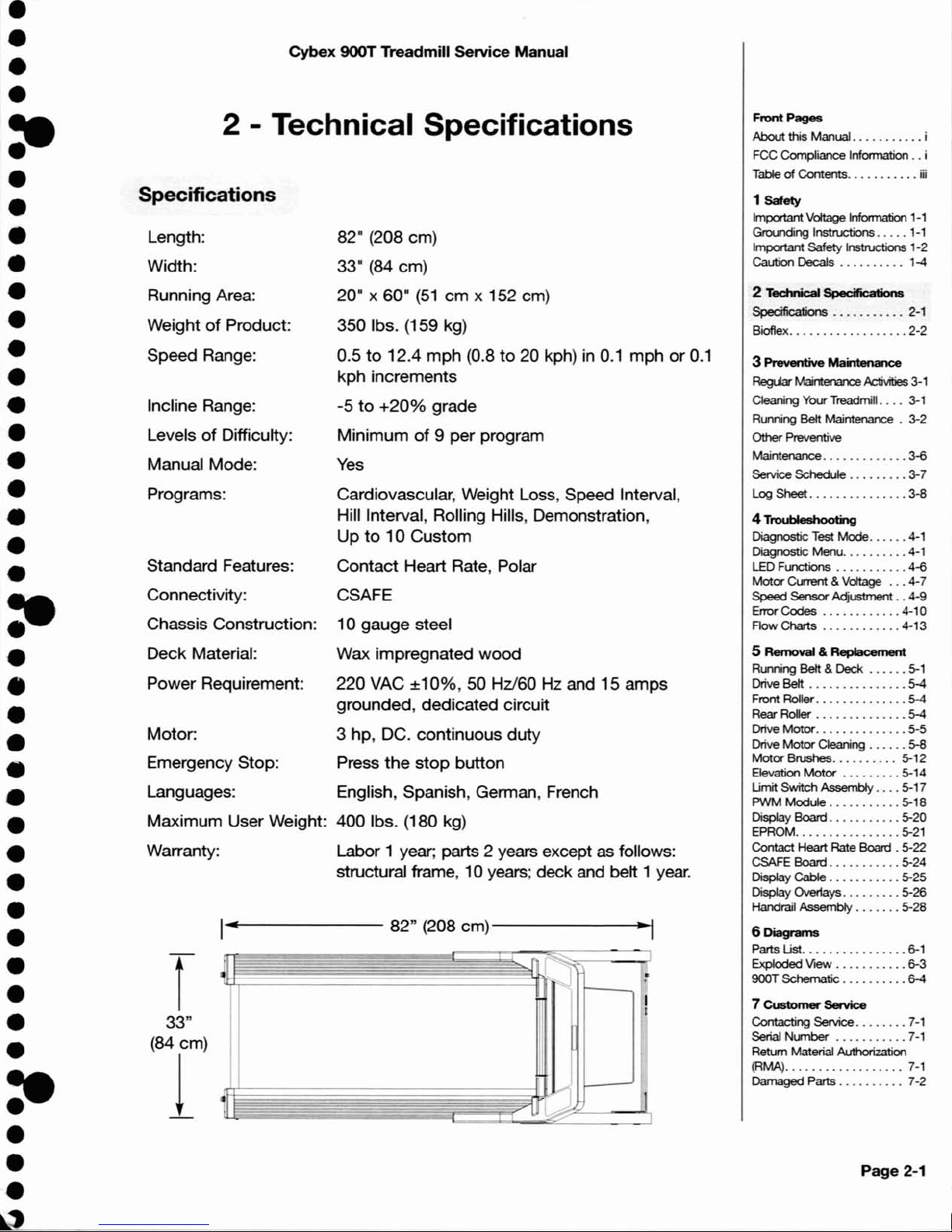
82" (208 cm)
33" (84 cm)
20" x 60"
(51
cm
x 152 cm)
350 Ibs. (159 kg)
0.5
to
12.4 mph (0.8to20 kph)in0.1
mphor0.1
kph increments
-5
to
+20%
grade
Minimum
of
9 per program
Yes
Cardiovascular, Weight Loss, Speed Interval,
Hill Interval, Rolling Hills, Demonstration,
Up
to10Custom
Contact Heart Rate, Polar
CSAFE
10 gauge steel
Wax impregnated
wood
220 VAC
±10%,
50 Hz/60 Hz and 15 amps
grounded, dedicated circuit
3 hp, DC. continuous duty
Press
the
stop
button
English, Spanish, German, French
400 Ibs. (180 kg)
Labor 1 year; parts 2 years except as follows:
structural frame, 10 years; deck and belt 1
year.
Length:
Width:
Running Area:
Weight
of
Product:
Speed Range:
Incline Range:
Levels
of
Difficulty:
Manual Mode:
Programs:
Standard Features:
Connectivity:
Chassis Construction:
Deck Material:
Power Requirement:
Motor:
Emergency Stop:
Languages:
Maximum User Weight:
Warranty:
Specifications
•
•
•
•
:e
•
•
•
•
•
•
•
•
•
•
•
•
•
•
•
:e
•
•
•
•
•
•
•
•
•
•
•
•
•
•
•
:e
•
•
•
~,
Page 14
Page
2-2
Cybex 900T Treadmill Service Manual
Bioflex
The Bioflex system used on the 900T is optimized
for
lateral stability. This is accomplished
through
the use of a 10 gauge steel frame and critically
damped
rear wheels. The heavy
gaugeofthe steel frame provides a rigid structuretotransfer
the
landing
shocktothe
damped
wheels so that they can effectively absorb the impact.
•
•
•
•
-:
•
•
•
•
•
•
•
•
•
•
•
•
•
•
•
•
•
•
•
•
•
•
•
•
•
•
•
•
•
•
•
e:
•
•
•
Page 15
•
•
•
•
:e
•
•
•
•
•
•
•
•
•
•
•
•
•
•
•
:e
•
•
•
•
•
•
•
•
•
•
•
•
•
•
•
:e
•
•
•
Cybex 900T Treadmill Service Manual
3 - Preventive Maintenance
Regular Maintenance
Activities
Preventive maintenance activities
must
be performedtomaintain normal
operation
of
your treadmill. Keeping a log sheetofall maintenance actions will
assist you
in
staying current with all preventive maintenance activities. See Log
Sheet in this chapter.
Cleaning Your Treadmill
When cleaning your treadmill spray a mild cleaning agent, such as a water and
dishsoap solution, on a clean cloth first,
and
then wipe
the
treadmill with the
damp
cloth.
NOTE: Do
not
spray cleaning solution directly on the treadmill. Direct
spraying
could
cause damage to the electronics
and
may void the
warranty.
! WARNING: To
prevent
electrical
shock,
be
sure
that
powerisshut
off
and
the
treadmillisunplugged
from
the
electrical
outlet
before
perfonning
any
cleaningormaintenance
procedures.
After
Each
Use
-
Wipeupany liquid spills immediately. After each workout,
use a cloth
to
wipeupany remaining perspiration from
the
handrails and
painted surfaces.
Be careful not
to
spillorget excessive moisture between
the
edgeofthe
display panel and the console, as this
might
create an electrical hazard
or
cause failureofthe electronics.
As
Needed
- Vacuum any dustordirt
that
might
accumulate underoraround
the
900T. Motors are especially susceptibletodust
and dirt, and restricted
airflow can prevent adequate cooling
that
could shorten
motor
life. Cleaning
this area should be
done
as often as indicated in
the
Service Schedule.
! WARNING:
Keep
wet
items
away
from
inside
parts
of
the
treadmill.
Electrical
shock
could
occur
evenifthe
treadmill
is
unplugged.
Avoid
touching
the
wire
connections
at
the
endofthe
blue
capacitor
mounted
on
topofthe
aluminum
box
nexttothe
drive
belt.
Front
Pages
About
this Manual i
FCC
Compliance
Information
..
i
Table
of
Contents iii
1
Safety
ImportantVoltage Infoonation
1-1
Grounding Instructions
.....
1-1
Important Safety Instructions 1-2
Caution
Decals... ....
...
1-4
2 Tec:hnicaI Spec:ificatiol18
Specifications . . . . . . . . ...2-1
Bioflex
2-2
3
Preventive
Maintenance
FlegU<r
Mairtenance
Activities
3-1
Cleaning
Your
Treadmill. ...3-1
Running
Belt
Maintenance . 3-2
Other Preventive
Maintenance
3-6
Service Schedule
3-7
Log
Sheet
3-8
4
Troubleshooting
Diagnostic Test Mode 4-1
Diagnostic
Menu
4-1
LED Functions
4-6
Motor
CuTent & Voltage 4-7
Speed
Sensor Adjustment
..
4-9
Error
Codes
.4-10
Flow Charts 4-13
5 Removal &
Replacement
Running Belt & Deck 5-1
Drive
Belt 5-4
Front Roller 5-4
Rear Roller 5-4
Drive
Motor
5-5
Drive
Motor
Cleaning 5-8
Motor
Brushes. . . . . . . ...5-12
Elevation
Motor
5-14
Umit
Switch
Assembly
5-17
PWM
Module
5-18
Display
Board 5-20
EPROM 5-21
Contact Heart Rate Board . 5-22
CSAFE Board 5-24
Display
Cable
5-25
Display Overlays
5-26
Handrail
Assembly
5-28
6
Diagrams
Parts
Ust
6-1
Exploded
VieW
6-3
900T Schematic
6-4
7
Customer
Service
Contacting Service 7-1
Serial
Number
7-1
Return Material
Authorization
(RMA)
7-1
Damaged
Parts 7-2
Page
3-1
Page 16
Page
3-2
Cybex
900T Treadmill
Service
Manual
To
clean the
motor
components, you
must
remove the
two
Phillips head screws that hold the
motor
cover in place. Lift the cover, and
put
it and the screws aside. Use a vacuum
attachment
or
hand vacuumtoclean
the
exposed elevation assembly, drive motor, lower
electronics and the surrounding areas.
Also use a
dry
cloth
for
the areas that you can't reach with the vacuum cleaner. If the machine
has not been used
for
some timeoris excessively dirty, use a
dry
clothtowipe all exposed
areas. Replace the cover and screws when finished.
With
the
helpofanother person, lift
the
rearofthe treadmill and roll it back from its present
position
soasto
vacuum
the
floor area underneath the unit. Wipe clean the undersideofthe
900T
to
prevent dirt and
dust
build-up. When finished, return the treadmilltoits normal
position.
Contact
Heart
Rate
Grips
- Contaminants, such as hand lotions, oils or body powder, may
come
off
on the contact heart rate grips. These can reduce sensitivity and interfere with the
heart rate signal. It is recommended that the user have clean hands when using the contact
heart rate. Clean the grips using a cloth dampened with a cleaning solution containing alcohol.
The grips are the only part
of
the treadmill you should use a cleaning solution containing alcohol.
In
addition, the nickel plating on the 900T may become tarnished and blackened with time.
This may reduce sensitivity and interfere with the heart rate signal. Use
an
emery cloth
to
remove
the
tarnish from
the
exposed nickel plating on
the
heart rate grips.
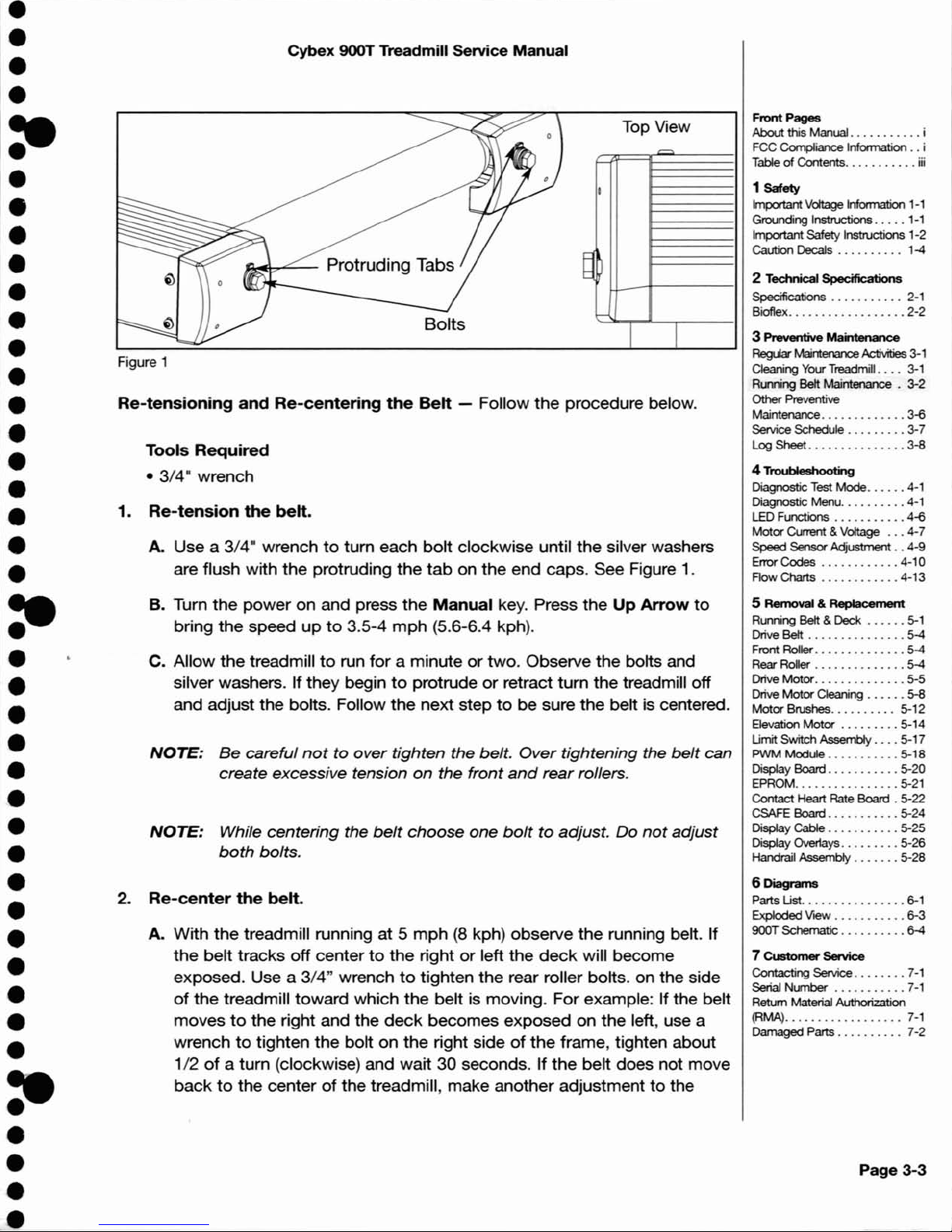
Running Belt
Maintenance
Belt
and
Deck
- Clean
the
belt and the
deck
surfacestominimize the effectoffriction
between
the
wood
deck
and the running belt. Clean the undersideofthe running belt and the
topofthe running
deck
surface by wiping them with a clean dry towel. This should be done
often
to
prevent premature wearofthe deck, running belt, and the drive
motor
system. See
the
Service Schedule in this chapter
to
determine the minimum recommended cleaning.
The running belt may become loose and slip on the drive roller with each foot plant. The 900T
is equipped with visual indicators
of
belt tension. These are located at the rearofthe treadmill
where the
two
3/4·
bolts protrude from the plastic end caps. See Figure 1. These are
designed
to
indicate if
the
running belt is at the proper tensiontoinsure safe operationofthe
unit. If
the
belt has become loose,
the
silver colored washer located under the bolt will move
out slightly from
the
protruding
tab
molded in the end cap. See the Service Schedule in this
chapter
to
determine the minimum recommended checkingofthe belt tension.
•
•
•
•
e:
•
•
•
•
•
•
•
•
•
•
•
•
•
•
•
~
•
•
•
•
•
•
•
•
•
•
•
•
•
•
•
•
e:
•
•
•
Page 17
•
•
•
•
:e
•
•
•
•
•
•
•
•
•
•
•
•
•
•
•
:e
•
•
•
•
•
•
•
•
•
•
•
•
•
•
•
:-
•
•
•
Cybex 900T Treadmill Service
Manual
Top View
.Q,ooI!b-""---
Protruding Tabs
Bolts
Figure 1
Re-tensioning
and
Re-centering
the
Belt
- Follow
the
procedure below.
Tools
Required
•
3/4
10
wrench
1.
Re-tension
the
belt.
A.
Use a 3/4" wrenchtoturn each
bolt
clockwise until the silver washers
are flush with the protruding
the
tab
on the end caps. See Figure 1.
B. Turn
the
power on and press
the
Manual
key. Press the
Up
Arrow
to
bring the speedupto
3.5-4
mph
(5.6-6.4 kph).
c.
Allow
the
treadmilltorun for a minuteortwo. Observe the bolts and
silver washers. If they begin
to
protrudeorretract turn the treadmill off
and adjust the bolts. Follow the next step
to
be sure the beltiscentered.
NOTE:
Be
careful
nottoover
tighten the belt.
Over
tightening the
belt
can
create excessive tension
on
the front
and
rear
rollers.
NOTE:
While
centering
the
belt
choose
one
bolttoadjust. Do
not
adjust
both
bolts.
2.
Re-center
the
belt.
A. With the treadmill running at 5
mph(8kph) observe the running belt. If
the
belt tracks off centertothe
right or left the
deck
will become
exposed. Use a
3/4" wrench
to
tighten the rear roller bolts. on the side
of
the treadmill toward which the beltismoving. For example: If the belt
moves
to
the right and the
deck
becomes exposed on the left, use a
wrench
to
tighten the bolt on the right sideofthe
frame, tighten about
1/2
of
a turn (clockwise) and wait30seconds. If
the
belt does not move
backtothe centerofthe treadmill, make another adjustmenttothe
Front
Pages
About
this Manual i
FCC Compliance Information
..
i
Table
of
Contents iii
1
Safety
Important Voltage Information 1-1
Grounding Instructions
.....
1-1
Important
Safety Instructions 1-2
Caution Decals . . . . . . . .
..
1-4
2
Technical
Specifications
Specifications 2-1
Bioflex
2-2
3
Preventive
Maintenance
RegtW
Maintenance
Activities 3-1
Cleaning Your
Treadmill. ...3-1
Running Belt Maintenance .
3-2
Other
Preventive
Maintenance
3~
Service Schedule
3-7
Log Sheet
3-8
4 Troubleshooting
Diagnostic
Test
Mode 4-1
Diagnostic Menu 4-1
LED Functions
4~
Motor
Current & Voltage'"4-7
Speed Sensor Adjustment..4-9
Error Cocles
4-10
Row Charts
4-13
5 Removal &
Replacement
Running Belt & Deck 5-1
Drive
Belt . . . . . . . . . . . . . . .
5-4
Front Roller
5-4
Rear Roller
5-4
Drive
Motor
5-5
Drive
Motor
Cleaning 5-8
Motor
Brushes 5-12
Elevation
Motor
5-14
Limit
Switch
Assembly
5-17
PWM
Module
5-18
Display
Board
5-20
EPROM 5-21
Contact Heart
Rate
Board .
5-22
CSAFE Board
5-24
Display Cable
5-25
Display Overlays 5-26
Handrail Assembly
5-28
6
Diagrams
Parts List 6-1
Exploded
VieW
6-3
900T Schematic 6-4
7
Customer
Service
Contacting Service 7-1
Serial
Number
7-1
Return Material Authorization
(RMA)
7-1
Damaged Parts 7-2
Page 3-3
Page 18
Page
3-4
Cybex 900T Treadmill Service
Manual
same
bolt.
Once
the
running belt has been adjusted
closertothe
centerofthe
treadmill
use
about
1/4ofa
turn
until the belt has been stabilized.
B. After
the
belt has been centered,
check
the
belt tension again.
Make
sure
the
running
belt tension is
tight
enough so that
the
belt does
not
sliporhesitate when stepped on.
Walk on
the
treadmill at 3.5-4 mph (5.6-6.4 kph) and every 4thto5th
step
throw
your
weight into
your
steptofeel if the belt is slipping. If
the
belt
does
slip, use a wrench
to
equally tighten
both
rear roller adjustment bolts
1/2ofa
turn
(clockwise). Adjust
the
belt
until
no
further slipping is felt. If the running belt continuestoslip
the
drive belt could
be
loose.
NOTE: The springs may eventually compress slightly.Ifthey compress the silver washers
may no
longerbeflush with the protruding tabonthe
end
caps when the
belt
is
properly tensioned.
The
washers willbepositioned deeper into the
end
cap
and
not
be
as visible.
Checking
the
Belt
and
Deck
Surfaces
- The running belt
and
deck
should
be checked
periodically
for
any excessive wear.Inan
efforttomake sure
that
the
running belt operates
properly, visually
inspect
the
belt on a weekly basistomake sure
that
there are no tears
or
fraying in
the
belt material.
To
inspect
the
edgesofthe
belt, it is necessarytoremove
the
motor
cover
and plastic side
rails. Follow these steps:
Tools
Required
• Phillips head
screwdriver
• Flat head
screwdriver
•
3/16·
Allen
wrench
• Dry towel
1.
Turn
the
power
off.
A. Turn
the
main
power
switch on the
front
paneltothe
off
(0)
position.
B. Unplug
the
treadmill from
the
power
outlet.
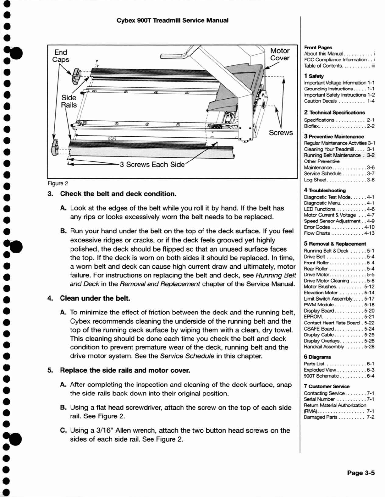
2.
Remove
the
motor
cover
and
side
rails.
A. Remove
the
two
Phillips head screws
that
fasten
the
motor
covertothe
frame. Lift
the
cover
and set it aside. This will allow youtoremove
the
side
rails. See Figure 2.
B. Using a
3/16"
Allen wrench, remove
the
two
button head
screwsonthe
sidesofeach
side
rail. See Figure 2.
C. Using a flat
head
screwdriver, remove
the
screw on
the
topofeach side rail. See
Figure 2.
D. Grasp
the
top
edgeofeach side rail and pull up and
away
from
the
deck. This will
enable
youtosee
the
deck
and edgesofthe
belt. It is
not
necessarytoremove
the
side rails
completely
off
the
frame.
•
•
•
•
e:
•
•
•
•
•
•
•
•
•
•
•
•
•
•
•
e:
•
•
•
•
•
•
•
•
•
•
•
•
•
•
•
e:
•
•
•
Page 19
4.
Clean
under
the
belt.
Front
Pages
About
this Manual i
FCC Compliance Information
..
i
Table
of
Contents iii
2 Technical Specifications
Specifications . .
.. ..
. . ...2-1
Bioflex 2-2
Page 3-5
1
Safety
ImportantVoltage Information 1-1
Grounding
Instructions
.....
1-1
Important Safety Instructions 1-2
Caution Decals
..
........
1-4
3
Preventive
Maintenance
RegUar
Maintenance
Activities
3-1
Cleaning Your
Treadmill. ...3-1
Running Belt Maintenance . 3-2
Other
Preventive
Maintenance 3~
Service Schedule 3-7
LogSheErt
3-8
4
Troubleshooting
Diagnostic Test Mode 4-1
Diagnostic Menu 4-1
LED Functions
4~
Motor
Current & Voltage
4-7
Speed Sensor Adjustment..4-9
Error Codes
4-10
Flow Charts
4-13
5 Removal & Replacement
Running Belt &
Deck
5-1
Drive Belt 5-4
Front Roller
5-4
Rear Roller 5-4
Drive
Motor
5-5
Drive
Motor
Cleaning 5-8
Motor
Brushes 5-12
Elevation
Motor
5-14
Umit
Switch Assembly 5-17
PWM
Module
5-18
Display Board
5-20
EPROM 5-21
Contact Heart Rate Board . 5-22
CSAFE Board 5-24
Display Cable 5-25
Display Overlays
5-26
Handrail Assembly 5-28
6
Diagrams
Parts Ust 6-1
Exploded
VieW
........•.•
6-3
900T Schematic 6-4
7
Customer
Service
Contacting
Service
7-1
Serial Number 7-1
Retum Material Authorization
(RMA)
7-1
Damaged Parts...... . 7-2
Screws
~=======---3
Screws Each
Side
,
I
I
~'~,'I~~~
Side
Rails
Cybex
900T
Treadmill Service Manual
B. Run
your
hand under the belt on the
topofthe
deck
surface. If you feel
excessive ridges
or
cracks,orif the
deck
feels grooved yet highly
polished, the
deck
should be flipped so that an unused surface faces
the
top.
If the
deck
is worn on both sides it should be replaced.Intime,
a
worn
belt and
deck
can cause high current draw and ultimately,
motor
failure. For instructions on replacing the belt and deck, see Running
Belt
and
Deck in the Removal andReplacement chapterofthe Service Manual.
C. Using a
3/16"
Allen wrench, attach the
two
button head screws on the
sides
of
each side rail. See Figure 2.
A. After completing the inspection and cleaning
of
the
deck
surface, snap
the
side rails back down into their original position.
B. Using a flat head screwdriver, attach the screw on the
topofeach side
rail. See Figure 2.
A. Look at the edges
of
the belt while you roll it by hand. If the belt has
any rips
or
looks excessively worn the belt needstobe replaced.
End
Caps
A.
To
minimize
the
effect of friction between the
deck
and the running belt,
Cybex
recommends cleaning the undersideofthe running belt and the
topofthe
running deck surfacebywiping them with a clean,
dry
towel.
This cleaning should be done each time you check the belt and
deck
conditiontoprevent premature wearofthe deck, running belt and the
drive
motor
system. See the Service Schedule in this chapter.
5.
Replace
the
side
rails
and
motor
cover.
Figure 2
3.
Check
the
belt
and
deck
condition.
•
•
•
•
:-
•
•
•
•
•
•
•
•
•
•
•
•
•
•
•
=-
•
•
•
•
•
•
•
•
•
•
•
•
•
•
•
:e
•
•
•
Page 20
Page
3-6
Cybex 900T Treadmill Service
Manual
D. Lower the
motor
coverinplace and tighten the
two
Phillips screws. See Figure
2.
Other
Preventive
Maintenance
Cybex recommends that
the
following maintenance activities be completedbya qualified
service technician. These activities should be perfonned at the recommended intervals listed
in the
Service Schedule (located in this chapter):
Measure the
motor
brushes and replace worn motor brushes
Rotate, flip and replace the running deck.
Replace the running belt
Check the current
draw
Measure motor voltage at maximum speed, with no load
Refer
to
the 900T Service Manual
for
detailed procedures when completing the tasks listed
above. If you need
to
order a manual, call Cybex at 888-GO-CYBEX, 888-462-9239 or
in
some areas call 508-533-5183.
•
•
•
•
-:
•
•
•
•
•
•
•
•
•
•
•
•
•
•
•
~
•
•
•
•
•
•
•
•
•
•
•
•
•
•
•
•
-=
•
•
•
Page 21
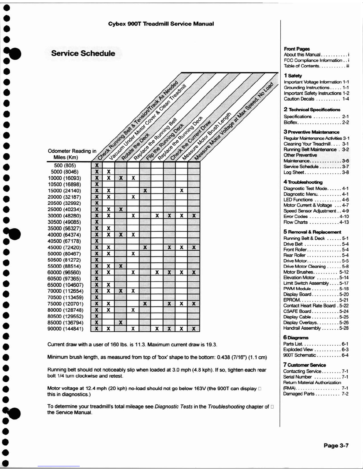
Current
draw
with a user
of
160 Ibs. is 11.3. Maximum current drawis 19.3.
Cybex
900T
Treadmill
Service
Manual
Front
Pages
About this
MMuaI
i
FCC
CompIia1ce
Information
..
i
Table
of Contents
iii
Page 3-7
1
Safety
Important
Voltage
Information
1-1
Gn:x.rong
Instructions
.....
1-1
Important Safety Instructions 1-2
Caution Decals . . . . . . . .
..
1-4
2 Technic:aI Spec;ificatiolI8
Specifications . . . . . . . . . . .
2-1
Bioflex.
. . . . . . . . . . . .
.....
2-2
3 Preventive Mai1tenan:e
RegLW Maintellalce
Ac1ivilies
3-1
Cleaning
Your
Treadmill. .
..
3-1
Fbring
Belt Maintelwlce . 3-2
Other
Preventive
~
~
Service
SchecUe 3-7
Log Sheet 3-8
4 TroubIeehooting
Diagnostic Test Mode
4-1
Diagnostic Menu 4-1
LED
Functions 4-6
Motor
Current & Voltage 4-7
Speed
Sensor
Adjustment
..
4-9
Error
Codes 4-10
Flow Charts 4-13
5 Removal & Replacement
Running Belt &
Deck
5-1
Drive Belt 5-4
Front
Roller
........•.....
5-4
Rear RoIer 5-4
Drive
Motor
5-5
Drive
Motor
Cleaning 5-8
Motor
Brushes 5-12
EJevation
Motor 5-14
Umit Switch Assembly 5-17
PWM Module 5-18
Display Board 5-20
EPR~
5-21
Contact
Heart Rate Board . 5-22
CSAFE
Board 5-24
Display Cable 5-25
Display 0vet1ays 5-26
Handrail Assembly 5-28
6Di11grams
Parts
List.
. . . . . . . . . . . . .
..
6-1
Exploded
VIeW
6-3
900T
Schematic
6-4
7Cl.I8tomer Service
Contacting
Service
7-1
Serial Number
7-1
Return Material Authorization
(RMA)
7-1
Damaged Parts . . . . . . . .
..
7-2
x
x
x
x x x x
x x x
x
x x x x x x x
x
x x x
x x x x
x x x x x x
x x x
x
x x x x
x
x x x x x x
x x x
x x
x
xx
x x x x x
x
x x x x
x x x
xx
x x x x x
x x
x x
x x
Service Schedule
500 (805)
5000 (8046)
1ססoo
(16093)
10500 (16898)
15000 (24140)
20000 (32187)
20500 (32992)
25000 (40234)
3ססoo
(48280)
30500 (49085)
35000 (56327)
40000 (64374)
40500 (67178)
45000 (72420)
5ססoo
(80467)
50500 (81272)
55000 (88514)
6ססoo
(96560)
60500 (97365)
65000 (104607)
7ססoo
(112654)
70500 (113459)
75000 (120701)
80000 (128748)
80500 (129552)
85000 (136794)
90000 (144841)
Running belt should
not
noticeably slip when loaded at 3.0 mph (4.8 kph).Ifso, tighten each rear
bolt 1/4
tum
clockwise and retest.
Minimum brush length,
as
measured from topof'box' shapetothe bottom: 0.438 (7/16") (1.1 em)
To
detennine yourtreadmill's total mileage see Diagnostic Tests in the Troubleshooting chapterof0
the Service Manual.
Motor voltage at 12.4 mph (20 kph) no-load should not
go
below 163V(the 900T can display 0
this in diagnostics.)
•
•
•
•
:e
•
•
•
•
•
•
•
•
•
•
•
•
•
•
•
I~
•
•
•
•
•
•
•
•
•
•
•
•
•
•
•
•
Page 22
Page
3-8
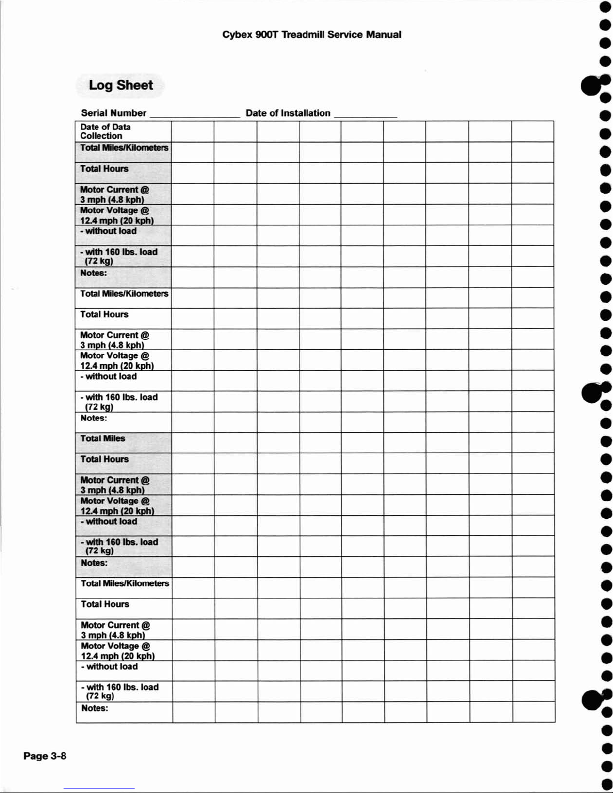
Log
Sheet
Serial Number
DateofData
Collection
Total MIesIKiIomeIers
TotalHotn
Motor
Cwrent
@
3
mph
(4.8 koh)
Motor
Voltage @
12.4
moh'2O
koh)
-
without
load
•
with
160 Ibs. load
(72 kg)
Notes:
Total Miles/Kilometers
Total Hours
Motor Current
@
3
moh
(4.8
kohl
MotorVoltage @
12.4
moh
(20
kohl
-
without
load
-
with
160 Ibs. load
(72 kg)
Notes:
Total
Miles
Total Hours
Motor
Current
@
3
moh
(4.8
koh)
Motor Voltage @
12.4
moh
'20
koh)
-
without
load
-with
160 Ibs. load
(72 kg)
Notes:
Total Miles/Kilometers
Total Hours
Motor Current
@
3 mDh '4.8
kohl
MotorVoltage @
12.4 moh (20
kohl
-
without
load
-
with
160
Ibs.load
(72 kg)
Notes:
Cybex
900T Treadmill Service
Manual
DateofInstallation
•
•
•
•
~
•
•
•
•
•
•
•
•
•
•
•
•
•
•
•
•
-:
•
•
•
•
•
•
•
•
•
•
•
•
•
•
•
~
•
•
•
•
Page 23
•
•
•
•
:e
•
•
•
•
•
•
•
•
•
•
•
•
•
•
•
:-
•
•
•
•
•
•
•
•
•
•
•
•
•
•
•
:e
•
•
•
Cybex
900T Treadmill
Service
Manual
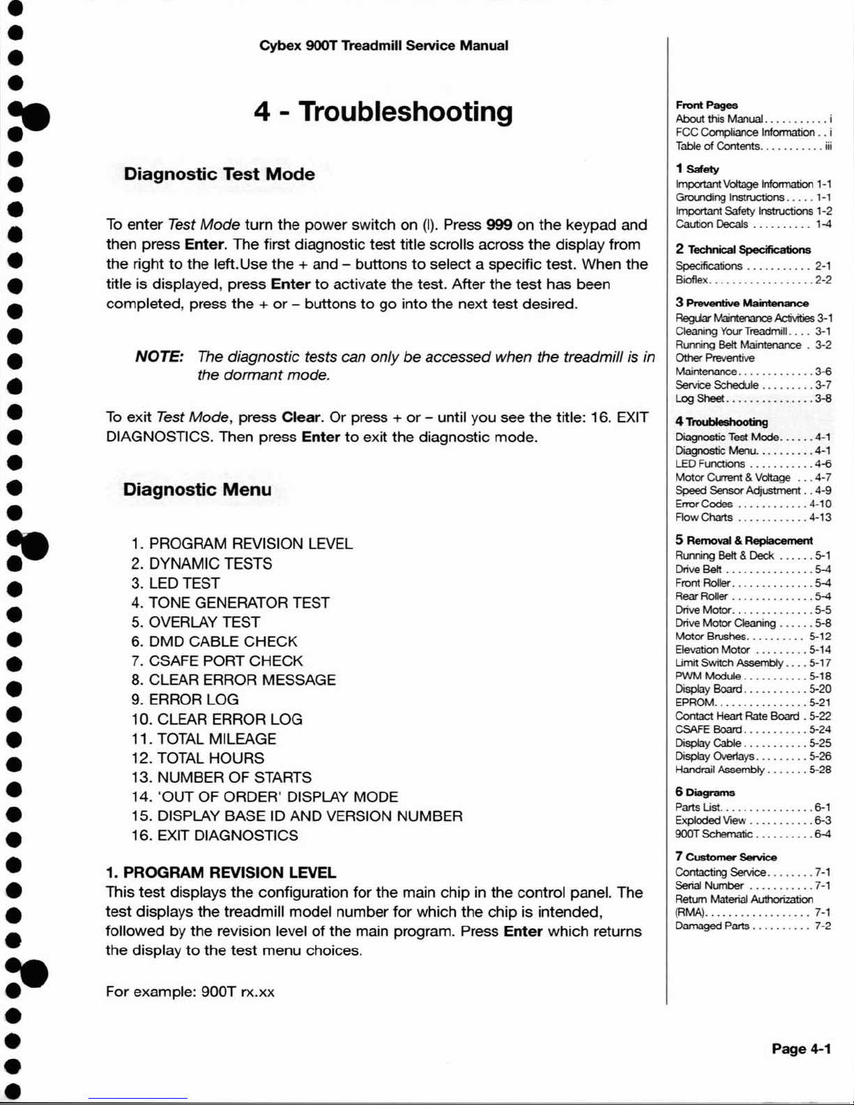
4 - Troubleshooting
Diagnostic
Test
Mode
To
enter
Test
Mode
turn
the power switch on
(I).
Press 999 on the keypad and
then press Enter. The first diagnostic test title scrolls across
the
display from
the right
to
the left.Use the + and - buttonstoselect a specific test. When the
title is displayed, press
Entertoactivate the test. After the test has been
completed, press
the+or
- buttonstogo into the next test desired.
NOTE:
The diagnostic tests can onlybeaccessed when the treadmill is in
the
dormant
mode.
To
exit Test Mode, press Clear. Or press +or- until you see
the
title: 16. EXIT
DIAGNOSTICS. Then press
Entertoexit the diagnostic mode.
Diagnostic
Menu
1. PROGRAM REVISION LEVEL
2. DYNAMIC TESTS
3. LED TEST
4. TONE GENERATOR TEST
5.
OVERLAY TEST
6.
DMD CABLE CHECK
7.
CSAFE PORT CHECK
8.
CLEAR ERROR MESSAGE
9. ERROR LOG
10. CLEAR ERROR LOG
11. TOTAL MILEAGE
12. TOTAL HOURS
13. NUMBER OF STARTS
14. 'OUT OF ORDER' DISPLAY MODE
15. DISPLAY BASE
10 AND VERSION NUMBER
16. EXIT DIAGNOSTICS
1. PROGRAM REVISION LEVEL
This
test
displays
the
configuration for the main chip in the control panel. The
test
displays the treadmill model number
for
which the chip is intended,
followed by the revision level
of
the main program. Press
Enter
which returns
the display
to
the
test
menu choices.
For example: 900T rx.xx
Front
Pages
About
this Manual i
FCC Compliance Information
..
i
TableofContents iii
1
Safety
ImportantVoltage Information
1-1
Grounding Instructions
.....
1-1
Important Safety Instructions 1-2
Caution Decals . . . . . . . .
..
1-4
2 Technical Specifications
Specifications . . . . . . . . ...2-1
Bioflex
2-2
3 Preventive
Maintenance
Reguar Maintenance
Activities
3-1
Cleaning Your Treadmill
....
3-1
Running
Belt
Maintenance . 3-2
Other Preventive
Maintenance
3-6
Service
Schedule 3-7
Log
Sheet
3-8
4 TroubIeshooU1g
Diagnostic
Test
Mode 4-1
Diagnostic Menu 4-1
LED Functions 4-6
Motor
Current & Voltage
4-7
Speed
Sensor
Adjustment..4-9
Error
Codes
4-10
Flow
Charts
4-13
5 Removal &
Replacement
Running
Belt
&
Deck
5-1
Drive
Belt . . . . . . . . . . . . . . .
5-4
Front Roller
5-4
Rear Roller
5-4
Drive
Motor
5-5
Drive
Motor
Cleaning 5-8
Motor
Brushes
5-12
Bevation
Motor
5-14
Umit
Switch
Assembly
5-17
PWM
Module
5-18
Display
Board
5-20
EPROM 5-21
Contact Heart Rate
Board
. 5-22
CSAFE
Board
5-24
Display Cable
5-25
Display Overlays
5-26
Handrail Assembly
5-28
6
Diagrams
Parts Us!. . . . . . . . . . . . . . . . 6-1
Exploded View
6-3
900T
Schematic 6-4
7
Customer
Service
Contacting Service 7-1
Serial
Number
7-1
Retum Material Authorization
(RMA) 7-1
Damaged Parts . . . . . . . .
..
7-2
Page
4-1
Page 24
Page
4-2
Cybex
900T Treadmill Service
Manual
Press
Enter
which returns the displaytothe test menu choices.
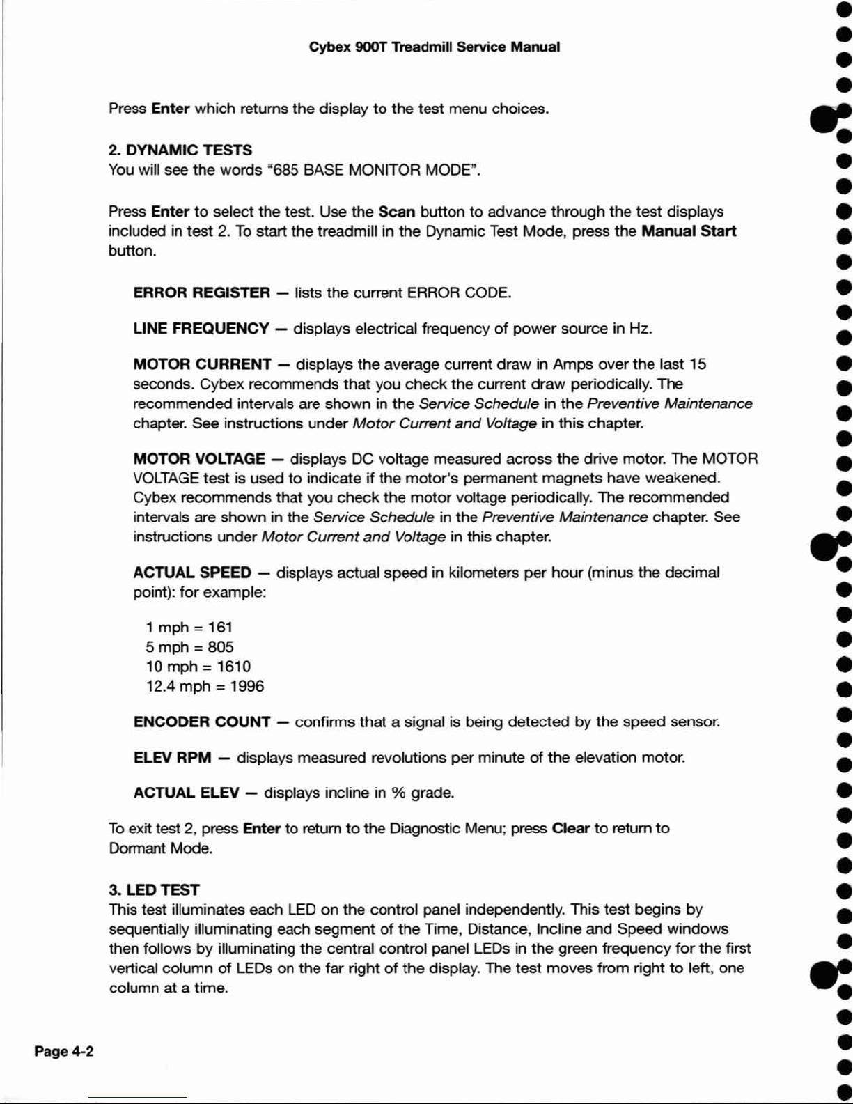
2. DYNAMIC TESTS
You
will see
the
words "685 BASE MONITOR MODE".
Press
Entertoselect the test. Use
the
Scan
buttontoadvance through
the
test displays
included in test 2.
To
start the treadmill in the Dynamic Test Mode, press the
Manual
Start
button.
ERROR REGISTER - lists the current ERROR CODE.
LINE FREQUENCY - displays electrical frequency
of
power
source in Hz.
MOTOR CURRENT - displays
the
average current
draw
in Amps over the last 15
seconds. Cybex recommends that you check the current
draw
periodically. The
recommended intervals are shown in the Service Schedule in
the
Preventive Maintenance
chapter. See instructions under
Motor
Current
and
Voltage in this chapter.
MOTOR VOLTAGE - displays DC voltage measured across
the
drive motor. The MOTOR
VOLTAGE
test
is usedtoindicate if the
motor's
permanent magnets have weakened.
Cybex recommends that you
check
the
motor
voltage periodically. The recommended
intervals are shown
in
the Service Schedule in the Preventive Maintenance chapter. See
instructions under
Motor
Current
and
Voltage in this chapter.
ACTUAL SPEED - displays actual speed in kilometers per hour (minus the decimal
point):
for
example:
1 mph =
161
5 mph =805
10 mph
=1610
12.4 mph
=1996
ENCODER
COUNT
- confirms that a signal is being detected by
the
speed sensor.
ELEV RPM - displays measured revolutions per minuteofthe
elevation motor.
ACTUAL ELEV - displays incline in % grade.
To
exit test 2, press Entertoreturntothe Diagnostic Menu; press Cleartoreturn
to
Dormant Mode.
3. LED TEST
This test illuminates each
LEDonthe
control panel independently. This test begins
by
sequentially illuminating each segmentofthe Time, Distance, Incline and Speed
windows
then followsbyilluminating the central control panel LEDs in the green frequency
for
the first
vertical column
of
LEDs on the far rightofthe display. The test moves from righttoleft, one
column at a time.
•
•
•
•
-=
•
•
•
•
•
•
•
•
•
•
•
•
•
•
•
e:
•
•
•
•
•
•
•
•
•
•
•
•
•
•
•
e:
•
•
•
Page 25
•
•
•
•
:e
•
•
•
•
•
•
•
•
•
•
•
•
•
•
•
:e
•
•
•
•
•
•
•
•
•
•
•
•
•
•
•
:e
•
•
•
Cybex
900T
Treadmill
Service
Manual
After the testofthe green LEOs is completed, the
test
repeats
for
the red
LEOs,
this
time
only illuminating the LEOs from the 0-15 range.
Pressing and holding the
+ button will illuminate all
of
the
green LEOs at one
time. Pressing and holding
the-button
will illuminate allofthe red
LEOs
from
0-15.
With test 3, you can easily locate any LED that may
notbeworking properly.
The display can be disassembled and the LED can be replaced with a
new one.
4. TONE GENERATOR
CHECK
This test checks the tone generator on the control panel.
When you press
Entertobegin this test, the display scrolls
the
message, "YOU
SHOULD HEAR 10 BEEPS", and the display will emit 10 audible beeps. A
defective tone generator will
not
produce any tones.
With test 4 you can determine if the tone generator needs
tobereplaced.
Press
+
or-to
incrementtoanother test.
5. OVERLAY TEST
This test checks that each button on the overlay is sending a signal
to
the
control panel.
When you press
Entertobegin this test, the control panel will display the
message:
"PRESS STOP TO END"
(it will scroll across the
top
lineofthe Dot Matrix
panel) and "KEY
HIT'
(stays illuminated on the middle line throughout the
test
until
Stop
is pressed).
Pressing any button will cause the
numberornameofthe
button
pressedtobe
displayed on
the
bottom lineofthe Dot Matrix panel.
NOTE: Press
Stop
last becauseitwill also cause
youtoexit
test 5
and
return to the diagnostic
test
menu.
If you locate a button that is
not
functioning properly, the overlay can be
replaced
to
correct the problem.
6.
DMD
CABLE
CHECK
This test checkstosee that
the
cable connecting the
upper
display board and
the lower control board
is
functioning property. If this cable is defective, no
Front
Pages
About
this Manual i
FCC
Compliance Information
..
i
Table
of
Contents
iii
1
Safety
ImportantVoltage Infoonation
1-1
Grounding Instructions
.....
1-1
ImportantSafety Instructions 1-2
Caution Decals . . . . . . . .
..
1-4
2
TeetV1icaI
Spec:ifications
Specifications . . . . . . . . ...2-1
Bioflex 2-2
3 Preventive Maintenance
RegUar
Maintenance
Activities
3-1
Cleaning
Your
Treadmill. ...3-1
Running
Belt
Maintenance . 3-2
Other
Preventive
Maintenance
3~
Service
Schedule 3-7
Log
Sheet.
3-8
4
TroubIeehooting
Diagnostic Test Mode 4-1
Diagnostic
Menu
4-1
LED Functions
4~
Motor
Current & Voltage 4-7
Speed
SensorAdjustment
..
4-9
Error~
4-10
Flow
Charts 4-13
5 Removal &
Replacement
Running
Belt
&
Deck
5-1
Drive Belt . . . . . . . . . . . . . . . 5-4
Front
Roller
5-4
Rear
Roller
5-4
Drive
Motor
5-5
Drive
Motor
Cleaning 5-8
Motor
Brushes 5-12
Elevation
Motor
5-14
Umit
Switch Assembly 5-17
PWM
Module 5-18
Display Board 5-20
EPROM
5-21
Contact Heart Rate Board . 5-22
CSAFE Board 5-24
Display Cable 5-25
Display Overlays 5-26
Handrail
Assembly 5-28
6
Diagrams
Parts
Ust
6-1
Exploded
VieW
.........•.
6-3
900T
Schematic 6-4
7 CustomerService
Contacting Service
7-1
Serial
Number
7-1
Retum
Material
Authorization
(RMA)
7-1
Damaged Parts 7-2
Page
4-3
Page 26
Page
4-4
Cybex
900T
Treadmill
Service
Manual
signals can be transmittedtoand from either board.
Press
Entertoactivate this test. If the cable is functioning, the display will
show
"LOWER
COMM
OK, LOWER TIMING OK"
If
the
cable is not transmitting
data
successfully,
the
message will scroll either:
"NO
LOWER
COMM,
LOWER TIMING
OK"
- indicates a problem with the communications
between
the
two
boards
or
"LOWER
COMM
OK, NO LOWER
TIMING"
- indicates a problem with the timing circuit
of
the
upper
board or
the
'RTS' (readytosend) wireinone or bothofthe display cables.
In
most
cases, if eitherofthe
"NO"
messages are present, replacing the upper and/or lower
display cable will correct the problem.
7. CSAFE PORT
CHECK
This test checks the CSAFE port, located on the rearofthe control panel console. When you
run this test,
the
display will indicate either
"OK"or"CSAFE PORT CONNECTION OPEN".
To
conduct
this test properly, the CSAFE
test
wire fixture needstobe plugged into the
connector at
the
backofthe console. Without
the
connector in place, the test will always read
CSAFE PORT CONNECTION OPEN
8.
CLEAR
ERROR MESSAGE
This
test
will allow youtoclear an error
code
displayedinthe control panel.
When
Enter
is pressed, "ERROR MESSAGE CLEARED" will scroll across the
topofthe
display.
9. ERROR LOG
This test lists the last 16 error
code
numbers
the
treadmill has recorded. The first number
to
scroll across the displayisthe
most
recent error code generated by the treadmill.
10.
CLEAR
ERROR LOG
This test will allow you
to
clear the log displayed in test
9.
When
Enter
is pressed, the message "ERROR LOG CLEARED" will scroll across the
top
of
display.
•
•
•
•
-=
•
•
•
•
•
•
•
•
•
•
•
•
•
•
•
e:
•
•
•
•
•
•
•
•
•
•
•
•
•
•
•
e:
•
•
•
Page 27
•
•
•
•
:e
•
•
•
•
•
•
•
•
•
•
•
•
•
•
•
:-
•
•
•
•
•
•
•
•
•
•
•
•
•
•
•
:e
•
•
•
Cybex
900T
Treadmill
Service
Manual
11.
TOTAL
MILEAGE
This
test
displays
the
actual accumulated total mileage,todate,
the
treadmill
has been used.
For example: "1348
MI"
The control panel displays the test results until you press +
or-.
12.
TOTAL
HOURS
This
test
displays
the
actual accumulated total time,todate, in hours and
minutes
the
treadmill has been used.
For example: HOURS RUN: 396:52
The control panel displays the test results until you press
+ or
-.
13.
NUMBER
OF
STARTS
This
test
displays
the
numberoftreadmill startups.
For example: 469 STARTS
14.
"OUT
OF
ORDER"
DISPLAY
MODE
Repeated pressingofthe
Enter
button
allows youtotoggle between activation
and deactivation
of
the
"OUT OF ORDER" message. The display will indicate
status as follows:
"OUT
OF ORDER" DISPLAY ON, TREADMILL DISABLED
or
"OUT
OF ORDER" DISPLAY
OFF,
TREADMILL RE-ENABLED
15. DISPLAY BASE
ID
AND
VERSION
NUMBER
This
test
displays
the
revision
numberofthe
software versionofthe program
chip in
the
lower board.
For example: BASE
10 #: 3 REVISION 3.01
16.
EXIT
DIAGNOSTICS
To
exit
the
Test Mode, returntothe
diagnostic menu and press +or- until you
see
the
"16. EXIT DIAGNOSTICS" message. Press
Entertoreturn
the
treadmill
to
its previous state before entering diagnostic mode.
Front
Pages
About this Manual i
FCC Compliance Information
..
i
Table
of
Contents
iii
1
Safety
ImportantVoltage Information
1-1
Grounding Instructions
.....
1-1
Important Safety Instructions 1-2
caution
Decals . . . . . . . ...1-4
2 Technical
Specifications
Specifications . . . . . . . . ...2-1
Bioflex 2-2
3 Preventive Maintenance
ReglJar
MaintenanceActivities 3-1
Cleaning YourTreadmill
....
3-1
Running
Belt
Maintenance . 3-2
Other Preventive
Maintenance 3-6
Service Schedule 3-7
Log Sheet
3-8
4 TroubIeehoota1g
Diagnostic Test Mode 4-1
Diagnostic
Menu 4-1
LED Functions
4-6
Motor
Ct.JTent
& Voltage 4-7
Speed
Sensor
Adjustment..4-9
Enor
Codes
4-10
Row
Charts
4-13
5 Removal &
RepIacemMt
Running Belt & Deck 5-1
Drive
Belt
5-4
Front Roller. . . . . . . . . . . . . . 5-4
Rear Roller 5-4
Drive
Motor
5-5
Drive
Motor
Cleaning 5-8
Motor
Brushes. . . . . . . ...5-12
Elevation
Motor
5-14
Limit
Switch
Assembly 5-17
PWM
Module 5-18
Display Board 5-20
EPROM 5-21
Contact
Heart
Rate Board . 5-22
CSAFE Board 5-24
Display
Cable
5-25
Display Overlays 5-26
Handrail Assembly 5-28
6
Diagrams
Parts List 6-1
Exploded
VieW
6-3
900T Schematic 6-4
7
Customer
Service
Contacting Service
7-1
Serial
Number
7-1
Retum Material Authorization
(RMA)
7-1
Damaged Parts 7-2
Page
4-5
Page 28

Page
4-6
Cybex
900T Treadmill
Service
Manual
LED Functions
The model 900T is equipped with diagnostic LEOs in the PWM module and the on the display
panel that are used
to
indicate a problem.
PWM
LEOs
In the 900T PWM, there are 2 LEDs in the
power
supply circuit that indicate proper voltage
to
the
display panel.
LED
1 -
LED1
is located on the PWM's printed circuit board (PCB) in
the
cornerofthe
board
near the display cable connector. This
LED
is usedtoverify that the PWM is supplying
the
proper
+SVDC outputtothe display assembly
for
the
normal operationofthe display's
microprocessor. This
LED
should be lit at all times while
power
is appliedtothe
PWM. If LED
1 is
not
lit, this shows that the PWM is not supplying +SVOCtothe
display and the PWM
should be replaced.
LED
2 - LED 2 is located near the centerofthe PCB, closetothe
transformer. This LED is
usedtoindicate the statusofthe DC voltage coming from the transformer on the PWM's
PCB. This voltage is the main source for the
power
supply circuitry and verifies that the
transformer's output is correct. LED 2 should be illuminated at all times while power is applied
to
the
PWM. If
LED
2 failstoilluminate or is flashing, this indicates that a problem exists in
the
transformer circuit and the PWM should be replaced.
Display
LEOs
The 900T display is equipped with 4 diagnostic LEOs
to
help determine an insufficient cable
connection or a failed sub assembly.
LED
9 - LED 9 is locatedinthe upper left
comerofthe display, facing the treadmill from
the
front, just above the DMD wafer connector. LED 9 is usedtoindicate an adequate supply
of
+SVOC from
the
treadmill's power supply circuitry in the PWM module. This LED should be lit
at all times while power
is
appliedtothe treadmill.
If LED 9
Is
not illuminated and PWM's LED 1 is illuminated, replace display cables.
If
LED
9 and
LED
10 are both illuminated and the display will not function, check the
communication LEDs
(11
and 12). If communication LEOs are OK, replace the display.
LED
10
- LED 10 is located near
the
upper left cornerofthe display just below
LED
9. LED
10
is usedtoindicateanadequate supplyof+4VOC from the treadmill's power supply
circuitry used
to
power the DOT MATRIX LEOs. This LED should be illuminated at all times
while power is applied
to
the treadmill.
If
LED
10 is not illuminated and PWM is supplying +4VOC, replace the display cables.
If LED 9 and 10 are both illuminated and
the
display will
not
function, check the
communication LEDs
(11
and 12). If communication LEOs are OK, replace the display.
•
•
•
•
e:
•
•
•
•
•
•
•
•
•
•
•
•
•
•
•
e:
•
•
•
•
•
•
•
•
•
•
•
•
•
•
•
e:
•
•
•
Page 29

•
•
•
•
:e
•
•
•
•
•
•
•
•
•
•
•
•
•
•
•
:-
•
•
•
•
•
•
•
•
•
•
•
•
•
•
•
:e
•
•
•
Cybex 900T Treadmill Service
Manual
LED11- LED
11
is located near the lower left cornerofthe display, below the
wafer connector. LED
11isusedtoindicate
'DATA
IN'. This LED illuminates
(flashes) when an input pulse (of data)
is
received by
the
display from the PWM
module. LED
11
should flashinresponsetoan initiation pulse from the display
and therefore should flash immediately after LED 12. If LED 12 flashes and no
response is seen from
LED
11, the problem will be either
the
display cables
or
PWM module.
LED
12
- LED 12 is located near the lower left cornerofthe display, below
LED 11. LED 12 is used
to
indicate
'DATA
OUT'. This LED illuminates (flashes)
when an
output
pulse (of data) is sent from the displaytothe
PWM module. If
LED 12 does
not
flash when powerisappliedtothe display, check
LEOs
9 and
10. If LED 9 and 10 illuminate, recycle the power
to
the treadmill. If problem
continues, replace the display.
Motor
Current
& Voltage
Cybex recommends that you check your
motor
current
draw
and measure
motor
voltage as scheduledinthe Service Scheduleinthe
Preventive
Maintenance
chapter. By performing these procedures
you
can evaluate the
performance
of
your drive motor and help prevent premature failure.
Tools
Required
• Phillips head screwdriver
• Flat head screwdriver
•
3/16·
Allen wrench
1.
Measure
current
draw.
A. With the treadmill
in
Dormant Mode, press 999
Enter.
B. Press +or-toscrolltoTest 2, Dynamic Tests, then press
Enter.
C. Press
Scan
until you reach "MOTOR CURRENT". Then press the
Manual
key. The belt will move at 1 mph (1.6 kph). You will see a
number
displayed which represents
motor
current in DC current.
D. Without standing on the belt, press the
+ key
to
bring the speedofthe
treadmill
upto3 mph (4.8 kph). At 3 mph (4.8 kph) average current
draw
should be between 2.00 and 3.00 without anyone on the
running belt.
E.
Now, have a user walk on the belt at 3 mph (4.8 kph). The maximum
current
draw
with a 160 Ibs.
(72
kg) user should
not
exceed 9.6. Even
with a heavier user, the current should not be more than 9.6. Press
Clear
to
exit Test Mode.
Front
Pages
About this Manual i
FCC
Compliance Information
..
i
Table
of
Contents iii
1
Safety
ImportantVoltage Infoonation 1-1
Grounding Instructions
.....
1-1
Important
Safety Instructions
1-2
Caution
Decals . . . . . . . .
..
1-4
2 Technical
Specifications
Specifications . . . . . . . . ...2-1
Bioflex
2-2
3 Preventive Maintenance
ReglJar
MaintenanceActivities 3-1
Cleaning YourTreadmill. .
..
3-1
Running Belt Maintenance .
3-2
Other
Preventive
Maintenance
3-6
Service SChedule 3-7
Log Sheet 3-8
4 Troubleshooting
Diagnostic Test
Mode
4-1
Diagnostic Menu 4-1
LED Functions
4-6
Motor
Current &Voltage
4-7
Speed SensorAdjustment..4-9
Error
Codes
4-10
Row
Charts 4-13
5
Removal&Replacement
Running Belt &
Deck
5-1
Drive Belt
5-4
Front Roller. . . . . . . . . . . . . .
5-4
Rear
Roller
5-4
Drive
Motor
5-5
Drive
Motor
Cleaning
5-8
Motor
Brushes
5-12
Elevation
Motor
5-14
Limit Switch Asserrt>Iy
5-17
PWM
Module
5-18
Display Board
5-20
EPROM
5-21
Contact
Heart Rate Board . 5-22
CSAFE
Board
5-24
Display Cable
5-25
Display Overlays
5-26
Handrail Assembly
5-28
6
Diagrams
Parts List 6-1
Exploded
VieW
6-3
900T SChematic
6-4
7
Customer
Service
Contacting Service 7-1
Serial
Number
7-1
Retum
Material Authorization
(RMA)
7-1
Damaged Parts. . . . . . . ...7-2
Page
4-7
Page 30

Page
4-8
Cybex 900T Treadmill Service
Manual
2.
Turn
the
power
off.
A.
Turn the main power switchinthe front paneltothe off (0) position.
B. Unplug the treadmill from the power outlet.
3.
Remove
the
motor
cover
and
side
rails.
A.
Remove the
two
Phillips head screws that fasten the
motor
covertothe
frame. Lift the
cover and set it aside. This will allow you
to
remove
the
side rails.
B. Using a 3/16" Allen wrench, remove the
two
button head screws on
the
sidesofeach
side rail.
C. Using a flat head screwdriver, remove the screw on
the
topofeach side rail.
D. Grasp the
top
edgeofeach side rail and pull up and away from the deck. This will
enable you
to
see the
deck
and edgesofthe belt. It is not necessarytoremove the
side rails completely off the frame.
4.
Check
the
belt
and
deck
condition.
A. Look at the edges
of
the belt while you roll it by hand. If the belt has any rips or looks
excessively worn the belt needstobe replaced.
B. Run your hand under the belt on
the
topofthe
deck
surface. If you feel excessive
ridges or cracks, or if the
deck
feels grooved, yet highly polished, the
deck
should be
flipped so that an unused surface faces the top. If the
deck
is worn on both sides it
should be replaced.
In
time, a worn belt and deck can cause high current draw and
ultimately,
motor
failure. See Running Belt
and
Deck
in
the
Removal
and
Replacement
chapterofthe
Service Manual.
6.
Replace
the
side
rails
and
motor
cover.
A.
Snap the side rails back
down
into their original position.
B. Using a flat head screwdriver, attach the screw on the
topofeach side rail.
C. Using a 3/16" Allen wrench, attach the
two
button head screws on the sidesofeach
side rail.
D. Lower the
motor
cover in place and attach it with the
two
Phillips screws.
7.
Measure
motor
voltage.
A. With the treadmill
in
Dormant Mode, press 999 Enter.
B. Press
+
or-to
scrolltoTest 2, Dynamic Tests, then press Enter.
C. Press SCan until you reach "MOTOR VOLTAGE". Then press
the
Manual
key.
D. Without standing on the belt, press the + keytobring the speedofthe treadmill up until
the treadmill reaches its highest speed,
12.4 mph
(20
kph).
You
will see a number
displayed which represents motor voltage. At this speed the measured voltage should be
•
•
•
•
e:
•
•
•
•
•
•
•
•
•
•
•
•
•
•
•
e:
•
•
•
•
•
•
•
•
•
•
•
•
•
•
•
e:
•
•
•
Page 31

•
•
•
•
:e
•
•
•
•
•
•
•
•
•
•
•
•
•
•
•
:-
•
•
•
•
•
•
•
•
•
•
•
•
•
•
•
:e
•
•
•
Cybex
OOOT
Treadmill Service Manual
about
188 VDC.
Motor
voltageat12.4
mph
(20 kph) with
no
load should
notgobelow 163 VDC. If it is below 163 VDC the magnets are weak and
the
drive
motor
should be replaced. Press
Cleartoexit
the
test.
Speed
Sensor
Adjustment
Tools
Required
• Phillips head screwdriver
1.
Turn
the
power
off.
A. Turn
the
main
power
switchonthe
front
paneltothe
off
(0)
position.
B. Unplug
the
treadmill from
the
power
outlet.
2.
Remove
the
motor
cover.
A. Remove
the
two
Phillips head
screws
that
fasten
the
motor
covertothe
frame. Lift
the
cover
and set it aside.
3.
Adjust
the
speed
sensor
gap.
A. Loosen
the
Phillips head
screw
that
attach
the
speed sensortothe
motor.
Adjust
the
gap
between
the
speed
sensor and
the
sheave should
be between .015 -
040"
(.0381 - .1016 cm).
B. Tighten
the
Phillips head screw.
4.
Turn
power
on
(I),
pluginthe
power
cord
and
test
for
any
speed
errors.
5.
If
any
errors
occur,
readjust
the
speed
sensor.
6.
Attach
the
motor
cover.
A. Lower
the
motor
cover in place and attach it with
the
two
Phillips screws.
Sheave
\
Gap
_-..;:;;~=~
Screw
_---I~llJ
Figure 3
Front
Pages
About
this Manual i
FCC Compliance Information
..
i
Table
of
Contents
iii
1 Safety
Important Voltage Infonnation 1-1
Grounding
Instructions
.....
1-1
Important
Safety Instructions
1-2
Caution Decals . . . . . . . .
..
1-4
2 Technical
Specifications
Specmcations 2-1
Bioflex
2-2
3 Preventive
Mamenance
Rego.Ja-
Maintenance
Activities
3-1
Cleaning
Your
Treadmill. .
..
3-1
Running Belt Maintenance .
3-2
Other
Preventive
Maintenance
3-6
Service Schedule
3-7
Log Sheet
3-8
4
Troubleshooting
Diagnostic Test
Mode
4-1
Diagnostic
Menu
4-1
LED Functions
4-6
Motor
Current & Voltage
4-7
Speed
Sensor
Adjustment..4-9
Error
Codes
4-10
Flow
Charts
4-13
5
Removal
&
Replacement
Running Belt & Deck 5-1
Drive Belt . . . . . . . . . . . . . . .
5-4
Front Roller
5-4
Rear Roller
5-4
Drive
Motor
5-5
Drive
Motor
Cleaning
5-8
Motor
Brushes. . . . . . . ...5-12
Elevation
Motor
5-14
Umit Switch
Assembly
5-17
PlNM Module _
5-18
Display Board
5-20
EPROM
5-21
Contact
Heart Rate
Board
.
5-22
CSAFE
Board
5-24
Display Cable
5-25
Display
Overlays
5-26
Handrail
Assembly
5-28
6
Diagrams
Parts Ust
.........•......
6-1
Exploded View
6-3
900T Schematic 6-4
7
Customer
Service
Contacting Service
7-1
Serial Number 7-1
Retum
Material Authorization
(RMA)
7-1
Damaged
Parts . . . . . . . .
..
7-2
Page
4-9
Page 32

Page
4-10
Cybex
900T
Treadmill
Service
Manual
Error
Codes
These codes notify youofa problem condition and provide a measureofsafety by stopping
the
treadmill. These codes can also helptoindicate the partofthe treadmill
most
likelytobe
causing the problem.
If you have a problem that interrupts an important operational area
of
the treadmill, you
may
see oneofthe following error
codes
displayed on the control panel. If you areinthe
middle
of
an exercise routine, these error codes initiateanimmediate treadmill shutdown.
All error
codes
are numbered and will appearinthe
dot
matrix display. Unless otherwise
described, occurrence
of
these error
codes
disables the operationofthe
treadmill.
An error
code
must be corrected before the machine will again be operable. Often,
you
can
clear the error code
by
simply turning the powertothe treadmill off, waiting a few seconds,
and then on again. An error
code
can also be cleared by entering the Diagnostic
Mode
and
going
to
Test 8 and clearing the code. Shouldanerror
code
reappear soon after cycling on
and off,
Cybex
recommends
that
you contact our Customer Service departmentoran
authorized Cybex service technician.
To
reach Cybex Customer Service from most areas call
888-GO-CYBEX or 888-462-9239. Otherwise call 508-533-4300
or
fax 508-533-5183.
NOTE: When recycling power, wait for the display togoout before turning
power
back on.
The following list will helptoexplain
the
specific error messages:
ERR
CODE
01:
PWM
Shutdown
This condition will cause an abrupt shutdown of the belt as the
motor
control detects a sharp
increase in drive current and immediately stops driving the belt. While some situations, such
as jamming the belt, may cause this error, an
ERR
CODE 1 without such abuse should
be
a
cause
for
extreme care and analysisbyan authorized service technician.
ERR
CODE
02:
Belt
Speed
Loss
This condition indicates that
the
speed pickup signal was lost continuously
for
longer than
one second after the
motor
successfully started. It normally indicates a failureofthe speed
pickup
or
an abrupt belt stoppage
duetoany motor, wiring,ormotor
controller failure.
ERR
CODE
03:
No
Belt
Speed
This condition indicates
that
no
speed is detected when the
motor
is first started. If
the
belt
moves slightly before
the
error occurs, it indicates a speed pickup problem. If it does
not
move at all,
the
indication is
foramotororcontroller problem.
ERR
CODE
04:
Belt
Over
Speed
The belt was running at least 1
mph
(1.6 kmh) above the set speed. It indicates a loss
of
control.
•
•
•
•
e:
•
•
•
•
•
•
•
•
•
•
•
•
•
•
•
e:
•
•
•
•
•
•
•
•
•
•
•
•
•
•
•
e:
•
•
•
Page 33

•
•
•
•
:e
•
•
•
•
•
•
•
•
•
•
•
•
•
•
•
:-
•
•
•
•
•
•
•
•
•
•
•
•
•
•
•
:e
•
•
•
Cybex
900T
Treadmill
Service
Manual
ERR
CODE
06:
Drive
Motor
Over
Voltage
The voltageonthe
motor
exceeded the maximum rated voltage duetoa
controller failure.This error usually indicates an open circuit across the drive
motor, such as a bad
motor
brush.
ERR
CODE
08:
Power
Fault
A
motor
controller failure is
detected
which will prevent full power being
switched on
for
the motor. This error is usually the resultofan intermittent
power
loss such as the
power
cord getting kickedorturning the power
switch
on
too
quickly when recycling
the
power.
ERR
CODE
10:
Elevation
Overs
peed
The elevation
motorisnot
within
the
controlled speed range. Either
the
motor
speed
detector
is generating extraneous information that will cause
the
elevationtobe
uncalibrated,orthe
motor
may be overdriven by a controller
failure.
NOTE:
Only the elevation system is disabledbyerrors
10,12and
13.
ERR
CODE
11:
No
Elevation
Speed
This condition indicates
thatnoelevation movement is detected when
the
elevation
motor
is powered. If
the
elevation system moves slightly before
the
error occurs,itindicates an elevation detector problem. If it
doesn't
moveatall,
it indicates an elevation
or
motor
controller problem.
ERR
CODE
12:
Elevation
Limit
This condition indicates
that
the
elevation limit switch has traveled outside
of
the
normal rangeofthe
treadmill
(-5%to20%). If the treadmill is at oneofthe
limits,
this
may
indicate
that
there
may
be another failure in
the
elevation
system which has caused loss
of
elevation calibration. Turning
the
power
switchtooff
(0)
then on
(I)
will cause the controllertoattempttoadjust
the
elevationbya
0.1
% adjustment in
the
appropriate direction. If the elevation
moves in
the
correct direction, cycling the power switch should correct
this
condition. If near a limit and cycling the power switch causes the elevation
to
move
further in the wrong direction, the treadmill should be turned off
and
a
service technician should
be
called. Repeated occurrencesofthis error
message should be addressed by a service technician.
If this error
occurs
and
the
treadmill is not near oneofthe
limits, it is an
indication
of
a failureofthe
limit detectors. If cycling
the
power
switch
does
not
remove
the
error condition,
the
treadmill may be used without the elevation
control until
the
problem is addressed.
Front
Pages
About this Manual i
FCC Compliance Information
..
i
Table of Contents iii
1
Safety
Important Voltage Information 1-1
Grounding
Instructions
.....
1-1
Important
Safety Instructions
1-2
Caution
Decals
. . . . . . . .
..
1-4
2 Technical
Specifications
Specifications . . . . .
.. ....2-1
Bioflex
2-2
3 Preventive
Maintenance
RegUcr Maintenance Activities 3-1
Cleaning Your Treadmill
....
3-1
Running
Belt Maintenance .
3-2
Other Preventive
Maintenance
3-6
Service Schedule 3-7
Log
Sheet
3-8
4 Troubleshooting
Diagnostic
Test
Mode 4-1
Diagnostic Menu 4-1
LED Functions
4-6
Motor
Current & Voltage..,
4-7
Speed
SensorAdjustment
..
4-9
Error
Codes
4-10
Flow Charts
4-13
5 Removal & RepIac:ement
Running Belt &
Deck
5-1
Drive
Belt 5-4
Front Roller
5-4
Rear Roller
5-4
Drive
Motor
5-5
Drive
Motor
Cleaning 5-8
Motor
Brushes 5-12
Elevation
Motor
5-14
Umit Switch Assembly
5-17
PWM
Module
5-18
Display Board
5-20
EPROM 5-21
Contact Heart Rate
Board .
5-22
CSAFE Board
5-24
Display
Cable
5-25
Display
Over1ays
5-26
Handrail Assembly
5-28
6
Diagrams
Parts Ust
6-1
Exploded
VieW
6-3
900T Schematic 6-4
7
Customer
Service
Contacting Service 7-1
Serial
Number
7-1
Retum Material Authorization
(RMA)
7-1
Damaged
Parts
. . ........
7-2
Page
4-11
Page 34

Page 4-12
Cybex 900T Treadmill Service Manual
ERR CODE
13: Elevation
Time
Umit
The elevation motor has been on
for
a longer time period than any movement should take.
The treadmill can still be used without the elevation until
the
condition is addressed. Cycling
the
power
switch normally clears this error.
ERR CODE
14:
Communications
Time-out
Lower
the signal from the upper consoletothe
motor
controller. Check the connections between the
console cables and the PWM as well as
the
connection into the display board.
ERR CODE
15:
Line
Tick
Loss
This is a warning condition thatisnoted onlyinthe Error Log. It does not disable
the
treadmill. It indicates a loss of, or an erratic line frequency count.
ERR CODE
16:
LossofNOVRAM
Data
Information stored in non-volatile memory (NOVRAM), such as the error log and user
programs,
is
different than that expectedbythe program stored in the EPROM. The
most
likely causeofthis error is a corruptedorfailing EPROM. If
the
EPROM is old, replace it with
the
latest version.
This error can also
occur
by bootingupthe
first time with a newer version EPROM.Inthis
case, simply clear the error.
ERR CODE
17:
No
Lower
Board
If no information is detected from a lower board, a special "mockup" mode is entered which
simulates normal treadmill user interface without lower board functions. This condition is
noted only
in
the error log file, and is primarily used
for
stand-alone console board service
testing.
ERR CODE
18:
Communications
Time-out
Upper
There is an interruptioninthe signal from
the
motor controllertothe upper console. Check
the connections between the console cables and the PWM as well
as
the connection into
the
display board.
•
•
•
•
e:
•
•
•
•
•
•
•
•
•
•
•
•
•
•
•
-:
•
•
•
•
•
•
•
•
•
•
•
•
•
•
•
e:
•
•
•
Page 35

Front
Pages
About
this
Manual i
FCC Compliance Infoonation
..
i
Table
of
Contents
iii
Page
4-13
1
Safety
Important
Voltage
Information
1-1
Grounding Instructions
.....
1-1
Important Safety Instructions 1-2
Caution
Decals
.......
...
1-4
2 Tedv1icaI Specifications
Specifications . . . . . . . . .
..
2-1
B~x
2-2
3 Preventive Maintenance
Reglja" Mairtenance Activities
3-1
Cleaning
Your
Treadmill. ...3-1
Running
Belt
Maintenance . 3-2
Other Preventive
~ntenance
3H6
Service Schedule 3-7
Log
Sheet
3-8
4T~
Diagnostic
Test
Mode
4-1
Diagnostic
Menu
4-1
LED Functions
4-6
Motor
Current &Voltage 4-7
Speed
Sensor
Adjustment
..
4-9
Error
Codes
4-10
Flow
Charts 4-13
5
Removal
&
Replacement
Running
Belt
&
Deck
5-1
Drive
Belt
5-4
Front Roller
5-4
Rear Roller 5-4
Drive
Motor
5-5
Drive
Motor
Cleaning 5-8
Motor
Brushes 5-12
Elevation Motor 5-14
Umit Switch Assembly 5-17
PWM
Module 5-18
Display
Board 5-20
EPROM 5-21
Contact
Heart
Rate
Board . 5-22
CSAFE
Board 5-24
Display
Cable 5-25
Display
Overlays
5-26
Handrail Assembly 5-28
60iagrans
Parts Ust. . . . . . . . . . . . . . . .
6-1
Exploded
View 6-3
900T Schematic 6-4
7
Customer
Service
Contacting Service
7-1
Serial Number
7-1
Return Material Authorization
(RMA)
7-1
Damaged
Parts....
. . . .
..
7-2
Replace
BELT
&
DECK
0
(or flip
deck
10
unused
SUlface)
Press
STOP
lWce
10
shut
down.
Enter
Diagnostics and
check
current
draw
(see
MoIor
Current
in chapter
•.
)
See
TRIPPED
BREAKER
flowchart
Replace BELT
&
DECK
0
(or flip deck
10
unused
surface)
YES
NO
Drive
motor
PWM module
Running
deck
Reset
0nJ
Off switch
10
recycle
power
Troubleshoot
ELEVATION
ASSEMBLY.
Repairorreplace
and
needed.
Plug Bevation
Cable
back
into
PIIIot.1
Cybex
900T
Treadmill
Service
Manual
Flowcharts
Tum power otf and
remove 2
moIor
leads
from green
connector
14-----<
on
PIIIot.1
and
unplug
eIevalion from
PIIIot.1.
Tum
power
back
on.
Troubleshoot DISPLAY.
DISPLAY CABLE, &
CONNECTIONS.
Repair
14-
__
--'
or
replace and needed.
Motor controller detects excessive drive current. The
motor
will abruptly
stop
when this error
code
is generated.The
most
likely causesofthis problem are as
follows, listed in order
of
probability.
Error
1:
PWM
Shutdown
Possible failurestocreate Error 1:
•
•
•
•
:e
•
•
•
•
•
•
•
•
•
•
•
•
•
•
•
:-
•
•
•
•
•
•
•
•
•
•
•
•
•
•
•
:e
•
•
•
Page 36

•
•
•
•
e:
•
•
•
•
•
•
•
•
•
•
•
•
•
•
•
e:
•
•
•
•
•
•
•
•
•
•
•
•
•
•
•
e:
•
•
•
NO
Replace DISPLAY
or
sendtoCybex
for
repair
YES
*To
enter
Diagnostic
Mode
press
999
and then press
Enter.
To exit Diagnostic
Mode
press Clear.
Re-gap
speed
sensor
to
.015"-.040"
(.0381-.1016 em)
Reset
"On/Off"
switch
to
recycle
power
Reset
On/Off
switch
to
recycle
power
Cybex 900T Treadmill Service Manual
In
Diagnostics·
manually
push run belt with foot one
length
of
belt and
check
encoder
count
Speed Signal was lost
for
more than one second after the drive motor has
successfully started.
Possible failures
to
create Error 2:
Speed sensor
PWM module
Running deck
Speed sensor cable
Speed sensor adjustment
Error2:Belt
Speed
Loss
Page
4-14
Page 37

Front
Pages
About
this Manual i
FCC Compliance Infonnation
..
i
Table of Contents iii
Page
4-15
1
Safety
Important Voltage Infoonation 1-1
Grounding Instructions
.....
1-1
Important Safety Instructions 1-2
Caution
Decals
. . . . . . . .
..
1-4
2
Tedw1icaI
Specifications
Specifications " 2-1
Bioflex
2-2
3
~
Maintenance
RegUar Maintenance Activities 3-1
Cleaning Your Treadmill. .
..
3-1
Running Belt Maintenance . 3-2
Other Preventive
Maintenance
3-6
Service Schedule
3-7
Log Sheet 3-8
4
TroubIeehooting
Diagnostic Test
Mode
4-1
Diagnostic Menu 4-1
LED Functions
4-6
Motor
Current & Voltage
4-7
Speed Sensor Adjustment
..
4-9
Enor
Codes
4-10
Flow Charts
4-13
5 Removal &
Replacement
Running Belt & Deck 5-1
Drive Belt
5-4
Front
Roller
5-4
Rear
RoHer
5-4
Drive
Motor
5-5
Drive
Motor
Cleaning 5-8
Motor
Brushes. . . . . . . ...5-12
Elevation
Motor
5-14
Umit
Switch
Assembly
5-17
PWM
Module
5-18
Display
Board
5-20
EPROM 5-21
Contact Heart
Rate
Board
. 5-22
CSAFE Board 5-24
Display Cable 5-25
Display
OveI1ays 5-26
Handrail Assembly
5-28
60iagrarns
Parts Ust 6-1
Exploded
VieW
6-3
900T Schematic 6-4
7
Customer
Service
Contacting Service 7-1
Serial
Number
7-1
Retum Material Authorization
(RMA)
7-1
Damaged Parts . . . . . . . .
..
7-2
Replace
SPEED
SENSOR
Replace
P\Mv1
MODULE
or
send Cybex
for
repair
YES
NO
Reset
On/Off
NO
switch to recycle
power
Ensure that speed
sensorwires and
connections
are
secure
Replace DISPLAY
or
sendtoCybex
for
repair
YES
NO
Replace
P\Mv1
r.-:",::"--,,
MODULEorsend
to Cybex
for
repair
*To enter Diagnostic
Mode
press
999
and
then
press
Enter.
To exit Diagnostic
Mode
pressClear.
Cybex 900T Treadmill Service Manual
Reset ·On/Off"
switch to recycle
power
Speed sensor
Speed sensor cable
PWM module
REl-9apspeed
sensor to
.015·-.040·
(.0381-.1016 em)
In Diagnostics" manually
push
run belt with
foot
one
lengthofbelt and
check
encoder
count
Possible failurestocreate Error
3:
No speed signal is detected when treadmill is first started. The belt may move
briefly before the error occurs.
Error3:No
Belt
Speed
•
•
•
•
:e
•
•
•
•
•
•
•
•
•
•
•
•
•
•
•
:-
•
•
•
•
•
•
•
•
•
•
•
•
•
•
•
:e
•
•
•
Page 38

Page
4-16
Cybex 900T Treadmill
Service
Manual
Error4:Belt Over Speed
The measured belt speed exceeded the setpoint speed
by1mph
for 200 ms.
Possible failures to create Error
4:
PWM module
User created problem by forcefully pushing run belt (usually while elevated).
Reset ERROR code
and enter Diagnostics·;
check
Actual Speed in
Dynamic Tests
Replace
PW.Il
~--I~
MODULE or send
to Cybex for repair
*To
enter Diagnostic Mode press 999 and then press Enter.
To
exit Diagnostic Mode pressClear.
•
•
•
•
e:
•
•
•
•
•
•
•
•
•
•
•
•
•
•
•
e:
•
•
•
•
•
•
•
•
•
•
•
•
•
•
•
e:
•
•
•
Page 39

Possible failurestocreate Error
6:
Page 4-17
Front
Pages
About
this Manual i
FCC
Compliance Infonnation..i
TableofContents iii
2 Technical
Specifications
Specifications . . . . . . . . ...2-1
Bioflex
2-2
3
Prwsrtive
Maintenance
ReglJar
MaintenanceActivities 3-1
Cleaning Your Treadmill. .
..
3-1
Running
Belt Maintenance .
3-2
Other Preventive
~ntenance
3-6
Service Schedule 3-7
Log
Sheet
3-8
4 Troubleshooting
Diagnostic
Test
Mode 4-1
Diagnostic
Menu
4-1
LED Functions
4-6
Motor
Current & Voltage 4-7
Speed
SensorAdjustment
..
4-9
Error
Codes
4-10
Flow Charts
4-13
5 Removal &
Replacement
Running
Belt
& Deck 5-1
Drive
Belt . . . . . . . . . . . . . . .
5-4
Front Roller 5-4
Rear Roller
5-4
Drive
Motor
5-5
Drive
Motor
Cleaning 5-8
Motor
Brushes. . . . . . . .
..
5-12
Elevation
Motor
5-14
Umit
Switch
Assembly
5-17
PWM
Module
5-18
Display Board
5-20
EPROM 5-21
Contact Heart
Rate
Board . 5-22
CSAFE Board
5-24
Display Cable
5-25
Display Overlays 5-26
Handrail Assembly
5-28
6 DiagI
allis
Parts
Ust
6-1
Exploded
VIeW
6-3
900T Schematic 6-4
7
Customer
Service
Contacting Service 7-1
Serial
Number
7-1
Return
Material
Authorization
(RMA)
7-1
Damaged Parts . . . . . . . ...7-2
1
Safety
Important
Voltage
Information
1-1
Grounding Instructions
.....
1-1
Important Safety Instructions 1-2
Caution Decals . . . . . . . .
..
1-4
YES
Check
resistance
of
drive
motor
at
PVIIv1
plug (TB1;
pins3and
4
unplugged)
Reset
OnIOff
switch
to
recycle
power
Cybex
900T
Treadmill
service
Manual
Check
both
MOTOR
BRUSHES
and
replace
if
necessary
Check
drive
motor
wiring
and
plugs
to
Replace
PII\M
ensure
all
connnections
I------+-l
MODULEorsend
to
are
secure
Cybex
for
repair
Motor
brush
PWM module
Error6:Drive
Motor
Over
Voltage
The measured motor voltage exceeded 200 VDC
for
200 ms.
•
•
•
•
~
•
•
•
•
•
•
•
•
•
•
•
•
•
•
•
:e
•
•
•
•
•
•
•
•
•
•
•
•
•
•
•
:e
•
•
•
Page 40

•
•
•
•
-:
•
•
•
•
•
•
•
•
•
•
•
•
•
•
•
-:
•
•
•
•
•
•
•
•
•
•
•
•
•
•
•
e:
•
•
•
Replace
CAPACITOR
Call an electrician
to resolve low
voltage problem
NO
Replace PIII.M
MODULE or send
;r-_~
to Cybex for
repair
Using a VOM, check
VAC to the treadmill
from the wall outlet
Replace components
listed above one at
a time until problem
is resolved
Problem exists in either:
LINE FILTER
or
PIII.M MODULE
or
ON/OFF SINITCH
YES Replace PIII.M
MODULE
Cybex
900T Treadmill
Service
Manual
PWM module
Low
line voltage
Faulty connection
On/off
switch
Capacitor
Line filter
Check to ensure the
wires to the capacitor
are connected to the
correct polarity
Error8:Power
Fault
Possible failurestocreate Error
8:
The drive
motor
supply was detected below 190 VDC
for
5 seconds.
Page
4-18
Page 41

YES
Page
4-19
Front
Pages
About this Manual i
FCC Compliance Information
..
i
Table of Contents iii
2 Technical
Specifications
Specifications . . . . . . . . .
..
2-1
Bioflex
2-2
3
~
MairlteNn:e
RegliarMaintenance
.Activities
3-1
Cleaning
Your
Treadmill. ...3-1
Running Belt Maintenance . 3-2
Other Preventive
Maintenance
3~
5ervice SChedule 3-7
Log Sheet
3-8
4 Troubleshooting
Diagnostic Test
Mode
4-1
Diagnostic
Menu
4-1
LED Functions
4-6
Motor
Current &Voltage
4-7
Speed Sensor Adjustment..4-9
Enor
Codes
4-10
Flow
Charts
4-13
5 Removal &
Replacement
Running Belt & Deck
5-1
Drive Belt . . . . . . . . . . . . . . . 5-4
Front Roller 5-4
Rear
Roller
5-4
Drive
Motor
5-5
Drive
Motor
Cleaning 5-8
Motor
Brushes 5-12
Elevation
Motor
5-14
Umit
Switch Assembly
5-17
PWM Module 5-18
Display Board 5-20
EPROM 5-21
Contact
Heart
Rate
Board
. 5-22
CSAFE Board 5-24
Display Cable 5-25
Display OveI1ays 5-26
Handrail Assembly
5-28
6
Diagrams
Parts
Ust
6-1
Exploded
VIeW
6-3
900T SChematic 6-4
7
Customer
Service
Contacting 5ervice
7-1
Serial Number
7-1
Return Material Authorization
(RMA)
7-1
Damaged
Parts
. . . . . . . .
..
7-2
1
Safety
Important Voltage
Information
1-1
Grounding
Instructions
.....
1-1
Important Safety Instructions
1-2
Caution Decals . . . . . . . .
..
1-4
NO
Twist
encoder
~----1~
wires
together
and
r--__"'-
retry elevation
Checktoensure
that
the
encoder
wires
are twisted
YES
Cybex 900T Treadmill Service Manual
Replace
PW,,1
'----------l~
MODULEorsend
14---------.J
to
Cybex
for
repair
Check
encoded
wheel
and
align if
not
centered
or
relaceifbroken
Possible failurestocreate Error 10:
PWM module
Elevation encoder
Error 10: Elevation Over Speed
The measured elevation
motor
speed exceeded 3800 rpm
for
2 seconds.
.~
•
•
•
:e
•
•
•
•
•
•
•
•
•
•
•
•
•
•
•
:e
•
•
•
•
•
•
•
•
•
•
•
•
•
:e
•
•
•
Page 42

~
•
•
•
e:
•
•
•
•
•
•
•
•
•
•
•
•
•
•
•
e:
•
•
•
•
•
•
•
•
•
•
•
•
•
•
•
e:
•
•
•
Replace
ELEVATION
ENCODER
Replace
p\IIIJI
MODULE or send
to Cybex for repair
Ensure that
encoder wires
J----.-<
are secure
Replace
PV\M
MODULE or send
to Cybex for repair
YES
YES
Replace
--------'
ElEVATION
BRAKE
Replace
ELEVATION
MOTOR
Cybex 900T Treadmill
service
Manual
Check resistance
of
elevation motor
PWM module
Elevation encoder
Elevation
motor
Possible failurestocreate Error11:
No movement is detected when the elevation motor
is
powered. This could
occur
with
or
without slight elevation
motor
movement.
Error
11:
No
Elevation
Speed
Page 4-20
Page 43

Front
Pages
About
this Manual i
FCC Compliance Information
..
i
Table
of Contents iii
Page 4-21
1
Safety
ImportantVoltage Information 1-1
Grounding
Instructions
.....
1-1
Important
Safety Instructions
1-2
Caution Decals . . . . . . . .
..
1-4
2 Technical Specifications
Specifications . . . . . . . . ...2-1
Bioflex
2-2
3
Prw«ltive
Maintenance
ReQUa"
MaintenanceActivities
3-1
Cleaning YourTreadmill. .
..
3-1
Running
Belt
Maintenance . 3-2
Other
Preventive
Maintenance
3-6
Service Schedule 3-7
Log Sheet
3-8
4 Troubleshooting
Diagnostic Test
Mode
4-1
Diagnostic
Menu
4-1
LED Functions
4-6
Motor
Current &Voltage
4-7
Speed
Sensor Adjustment..4-9
Error
Codes
4-10
Flow
Charts
4-13
5 Removal &
RepIac:ement
Running
Belt
& Deck 5-1
Drive Belt . . . . . . . . . . . . . . .
5-4
Front Roller
5-4
Rear Roller
5-4
Drive
Motor
5-5
Drive
Motor
Cleaning 5-8
Motor
Brushes. . . . . . . .
..
5-12
Elevation
Motor
5-14
Limit Switch Assembly
5-17
PWM
Module
5-18
Display Board
5-20
EPROM 5-21
Contact
Heart Rate Board .
5-22
CSAFE Board
5-24
Display Cable
5-25
Display Overlays
5-26
Handrail Assembly
5-28
6~
Parts List 6-1
Exploded
VieW
6-3
900T Schematic
6-4
7
Customer
5ervice
Contacting Service 7-1
Serial
Number
7-1
Retum
Material Authorization
(RMA)
7-1
Damaged
Parts . . . . . . . .
..
7-2
Check
wiring
on
limit
switches.
If
needed
replace
wiring
hamess
to
left
side
limit
switch.
YES
NO
Replace
LIMIT
SVIIITCH
YES
Check
left
side
~----1~
limit switch
with
Ohm
meter
NO
YES
Replace
PIMJI
>-~
MODULEorsend
to
Cybex
for
repair
Replace
ELEVATION
MOTOR
Check
wiring
on
limit
switches.
If
needed
replace
wiring
harness
to
right
side
limit
switch.
Cybex
900T Treadmill
Service
Manual
Check
right
side
limit
switch
with
Ohm
meter
and
properly
algin
switch
with
gear
rack
Does
treadmill
elevate
to
minimumormaximum
at
power-up?
Possible failurestocreate Error 12:
Elevation has gone past its normal operating limits
Limit switch is broken
Limit switch connection problem (wiring harness)
Error
12:
Elevation
Limit
Elevation right side gear rack limit switch is open.
,.~
•
•
•
:e
•
•
•
•
•
•
•
•
•
•
•
•
•
•
•
:-
•
•
•
•
•
•
•
•
•
•
•
•
•
•
•
:e
•
•
•
Page 44

~
•
•
•
-:
•
•
•
•
•
•
•
•
•
•
•
•
•
•
•
-:
•
•
•
•
•
•
•
•
•
•
•
•
•
•
•
e:
•
•
•
Replace
ELEVATION
MOTOR
NO
YES
Tighten GEAR to
YES elevation shaft!
check
for key in
keyway
YES Replace
CHAIN
Cybex 900T Treadmill Service Manual
Replace PVIIJI
MODULEorsend
to Cybex for repair
Elevation chain maybebroken
Drive gear may be loose
Elevation
motor
running
slow
Possible failurestocreate Error 13:
Elevation
motor
was driven
for
60 seconds without stopping, changing directions or reaching
a limit.
Error 13: Elevation Time Limit
Page
4-22
Page 45

Front
Pages
About this Manual i
FCC
Compliance Information
..
i
Table of Contents iii
Page 4-23
2 Technical Specifications
Specifications . . . . . . . . .
..
2-1
Bioflex
2-2
3 Prw«1tive
Mam8nance
RegUcr Mairtenance
Activities
3-1
Cleaning YourTreadmill. ...3-1
Running
Belt
Mairtenance
. 3-2
Other
Preventive
Maintenance 3~
Service
Schedule
3-7
Log
Sheet
3-8
4 Troubleshooting
Diagnostic Test
Mode
4-1
Diagnostic
Menu
4-1
LED Functions
4~
Motor
Current & Voltage
4-7
Speed
Sensor
Adjustment
..
4-9
Enor
Codes
4-10
Flow
Charts
4-13
5
Removal
& RepIaoement
Running
Belt
&Deck 5-1
Drive
Belt
5-4
Front
Roller
5-4
Rear
Roller
5-4
Drive
Motor
5-5
Drive
Motor
Cleaning 5-8
Motor
Brushes 5-12
Elevation
Motor
5-14
Limit Switch Assembly
5-17
PWM
Module
5-18
Display Board
5-20
EPROM
5-21
Contact
Heart
Rate
Board .5-22
CSAFE Board 5-24
Display Gable
5-25
Display 0ver1ays
5-26
Handrail Assembly
5-28
6
Diagrams
Parts List 6-1
Exploded
VIeW
6-3
900T Schematic 6-4
7 Customer
Service
Contacting Service 7-1
Serial
Number
7-1
Return
Material Authorization
(RMA)
7-1
Damaged
Parts...... . .
..
7-2
1
Safety
ImportantVoltage
Information
1-1
Grounding Instructions
.....
1-1
Important
Safety Instructions
1-2
Caution
Decals
. . . . . . . .
..
1-4
Replace
PIM.II
MODULE
or
send
to
Cybex
for
repair
Check
DISPLAY
CABLE
for
damage
YES
Check
DISPLAY
CABLE
for
damage;
replace
if
needed
Replace
DISPLAY
CABLE
FAIL
NO
Enter
Diagnostics·,
run
test 6, "DMD
Cable
Check"
Reset
OnIOff
switchtorecyde
power
Cybex 900T Treadmill Service Manual
Remove
display
back
cover
and
check
data
transfer
LED(12),
"DATA IN"toensure
thatitis
flashing
*To
enter
Diagnostic
Mode
press
999
and
then
press
Enter.
To exit
Diagnostic
Mode
press
Clear.
No valid messages received from the upper board for 3 seconds.
Error 14: Communication
Time
Out Lower
Possible failurestocreate Error 14:
Display board
PWM module
display cables
•
•
•
•
:e
•
•
•
•
•
•
•
•
•
•
•
•
•
•
•
~
•
•
•
•
•
•
•
•
•
•
•
•
•
•
•
•
!e
•
•
•
•
Page 46

•
•
•
•
-:
•
•
•
•
•
•
•
•
•
•
•
•
•
•
•
-:
•
•
•
•
•
•
•
•
•
•
•
•
•
•
•
e!
•
•
•
•
Check DISPLAY
CABLE for
damage. Replace if
needed.
NO Call an electrician
to resolve problem
FAlL
In Diagnostics·,
DynamicTests;
check frequency
in
Test 2
Replace
PVI.fJI
MODULE or send
to Cybex for repair
Cybex
900T
Treadmill
Service
Manual
*To enter Diagnostic Mode press 999 and then press Enter.
To
exit Diagnostic Mode press Clear.
In
Diagnostics· run
test 6, DMD Cable
Test
Error
15:
line
Tick
Loss
The
timing
has been lost from the lower board power line sync. This error
code
only shows
up
in
the
error log and will
not
interrupt the operationofthe treadmill.
PWM module
Display cable
Line frequency
outofspec
Page
4-24
Page 47

Front
Pages
About
this Manual i
FCC
Compliance
Information
..
i
Table
ofContents iii
Page 4-25
2 Tecf1nicaI Spec::ific:atio
IS
Specifications . . . . . . . . ...2-1
Bioflex
2-2
3 Preventive Maintenance
Reglja"Mantenance ActiIIilies 3-1
Cleaning Your Treadmill. ...3-1
Rl.nling
Belt
Maintenance . 3-2
Other
Preventive
Maintenance
3~
5ervice
Schedule
3-7
Log Sheet
3-a
4 Troubleshooting
Diagnostic Test
Mode
4-1
Diagnostic Menu 4-1
LED
Functions
4~
MotorCuTent & Voltage
4-7
Speed
SensorAdjustment
..
4-9
Error
Codes
4-10
Flow Cha1s
4-13
5 Removal & Replacement
RlM'll'ling Belt & Deck . . . ...5-1
Drive
Belt 5-4
Front
Roller
5-4
Rear
Reier
5-4
Drive
Motor
5-5
Drive
MotorCleaning
s-a
MotorBrushes
5-12
Elevation Motor 5-14
Limit Switch
Assembly 5-17
PWM
Module
5-18
Display Board
5-20
EPROM
5-21
Contact
Heart
Rate
Board
.5-22
CSAFE
Board
5-24
Display
Cable
5-25
Display Overlays 5-26
Handrail Assembly
5-28
6 DiaglanlS
Parts List. . . . . . . . . . . . . . . .
6-1
Exploded
VIeW
6-3
900T Schematic 6-4
7
Customer
Service
Contacting
5ervice
7-1
Serial Number 7-1
Return Material Authorization
(RMA)
7-1
Damaged
Parts . . . . . . . .
..
7-2
1 Safety
ImportantVoltage
Information
1-1
Grounding Instructions
.....
1-1
Important Safety Instructions
1-2
Caution
DecaJs
. . . . . . . .
..
1-4
NO
Replace
DISPLAY
or
sendtoCybex
~~
for
repair
"---'
YES
~--~
Replace
EPROM
I---~
Cybex 900T Treadmill Service Manual
Reset
0nJ0ff
switch
to
recycle
power
NOVRAM
Other misc. components
in
display
Novram data doesn't match EPROM version,
or
novram can't be written to.
Error
16:
LossofNOVRAM
Data
,..~
•
•
•
!e
•
•
•
•
•
•
•
•
•
•
•
•
•
•
•
•
•
•
•
•
•
•
•
:e
•
•
•
Page 48

Cybex 900T Treadmill Service Manual
t:
•
•
•
-:
•
•
•
•
•
•
•
•
•
•
•
•
•
•
•
•
•
•
•
•
•
•
•
•
•
•
•
•
•
•
•
e:
•
•
•
FAIL Replace DISPLAY
CABLE
YES Replace DISPLAY
~-
~
or send to Cybex
for repair
Replace
P\IIIVI
MODULE or send to
Cybex for repair
In
Diagnostics·, Test
6;
run
DMD Cable
Check
PASS
*To
enter Diagnostic Mode press 999 and then press Enter.
To
exit Diagnostic Mode press Clear.
Remove
back
cover of Display
and check LED
11
to seeifit
flashes to indicate data
received by the Display from
the
PWJI Module
Error 17: No Lower Board
No information is received from the lower board at power-up. This error
code
only shows up
in the error log and will not interrupt the operation
of
the treadmill.
Display cable
Lower board
Page 4-26
Page 49

Cybex 900T Treadmill Service Manual
Page 4-27
Front
Pages
About
this Manual i
FCC Compliance Information
..
i
Table
of
Contents
iii
2 TecfvlicaI
Specifications
Spec~
2-1
Bioflex
2-2
3 Preventive
Mainterwlce
RegtJcr MaintenanceActivities 3-1
Cleaning Your Treadmill. ...3-1
Running Belt Maintenance .
3-2
Other
Preventive
Maintenance
3~
Service Schedule 3-7
Log Sheet
3-8
4 Troubleshooting
Diagnostic Test Mode 4-1
Diagnostic
Menu
4-1
LED Functions
4~
MotorCurrent & Voltage
4-7
Speed Sensor Adjustment
..
4-9
Error
Codes
4-10
Flow
Charts 4-13
5 Removal &
Replacement
Running Belt & Deck
5-1
Drive Belt . . . . . . . . . . . . . . . 5-4
Front
Roller
..........•...
5-4
Rear Roller 5-4
Drive Motor 5-5
Drive
MotorCleaning 5-8
Motor Brushes 5-12
Elevation
Motor
5-14
Umit Switch
Assembly
5-17
PWM Module 5-18
Display
Board
5-20
EPROM 5-21
Contact
Heart
Rate
Board.5-22
CSAFE
Board
5-24
Display Cable 5-25
Display Overlays 5-26
Handrail Assembly 5-28
6
Diagrams
Parts Ust 6-1
Exploded
VieW
6-3
900T
Schematic 6-4
7
Customer
5ervice
Contacting Service
7-1
Serial Number
7-1
Return Material Authorization
(RMA)
7-1
Damaged Parts . . . . . . . ...7-2
1
Safety
Important Voltage Information 1-1
Grounding Instructions
.....
1-1
Important
safety
Instructions
1-2
Caution Decals . . . . . . . .
..
1-4
Replace DISPLAY
PANEL
or
send
to
Cybex
for repair
FAIL Replace DISPLAY
CABLE
YES
Replace
PV\fJI
MODULEorsend
to
Cybex for repair
PASS
"To enter Diagnostic
Mode
press 999 and then
press
Enter.
To
exit Diagnostic
Mode
press Clear.
In Diagnostics·. run test
6 "DMD CABLE
CHECK"
to
see if
problem exists in
display cable
Remove
back cover
of
display
and
check
to seeifboth LED
11
and LED 12 are flashing
(LED11should
echo
LED 12)
Error
18:
Communication
Time-out
Upper
Possible failures to cause no display:
Display cable
Lower board
An interruption has been indicated in the signal from the PWM module
to
the
display board.
:-
•
•
•
•
•
•
•
•
•
•
•
•
•
•
•
:e
•
•
•
~
•
•
•
:e
•
•
•
•
•
•
•
•
•
•
•
•
•
•
Page 50

Cybex 900T Treadmill Service
Manual
~
•
•
•
•
•
•
•
•
•
•
•
•
•
•
•
•
•
•
•
-:
•
•
•
•
•
•
•
•
•
•
•
•
•
•
•
e:
•
•
•
Call an electrician
to resolve problem
in
outlet
YES
Replace
PVIIv1
MODULEorsend to
..--~
Cybex for repair
Replace DISPLAY
CABLE
Check voltage from
the wall outlet to
ensure
230 VACI 220
VAC (50Hz)
NO
NO
--~~-----
Replace
PVIIv1
MODULE or send to
t-----~
Cybex for repair
Remove
PVIIv1
cover and
check LED 1 in
PVIIv1
module to see
if
it is lit,
indicating +5VDC supply
to display
Check LED 9 on the display
board near the waffer
connector from the
PVIIv1
module
Possible failurestocause no display:
PWM module
Display cable
Display board
No LEDs on the display light up after turning the on/off switchtothe
"on" position. The
display remains blank.
No
DisplayatPower-up
Page
4-28
Page 51

NOTE: This treadmill continually monitors the elevation system
and
will
usually identify any
problem
that occurs in this area. When a
problem
does existonthe elevation system, the failure will
be
stored
in the errorlog.
As
with
most
elevation failures, first check
the
error
log
to seeifan elevation failure has been detectedbythe
microprocesser. The
most
likely causesofthis problem are as
follows, listed in the
orderofprobability.
Possible failures
to
cause no elevation down:
Page 4-29
2
Technical
Specifications
Specifications 2-1
Bioflex
2-2
Front
Pages
About this Manual i
FCC Compliance
Information
..
i
Table
of
Contents iii
1 Safety
ImportantVoltage Information 1-1
Grounding Instructions
.....
1-1
Important Safety Instructions 1-2
Caution
Decals . . . . . . . .
..
1-4
3 Preventive
Maintenance
Regtjar Maintenance
Activities
3-1
Cleaning Your Treadmill. .
..
3-1
Running
Belt
Maintenance . 3-2
Other Preventive
Maintenance
3-6
Service Schedule 3-7
Log Sheet
3-8
4 Troubleshooting
Diagnostic Test
Mode
4-1
Diagnostic
Menu
4-1
LED
Functions
4-6
Motor
Current & Voltage
4-7
Speed Sensor Adjustment
..
4-9
Error
Codes
4-10
Flow
Charts 4-13
5
Removal
& Replacement
Running
Belt
&
Deck
5-1
Drive
Belt
. . . . . . . . . . . . . . .
5-4
Front
Roller
5-4
Rear
Roller
5-4
Drive
Motor
5-5
Drive
Motor
Cleaning 5-8
Motor
Brushes
5-12
Elevation
Motor
5-14
Umit Switch
Assembly
5-17
PWM Module
5-18
Display Board
5-20
EPROM 5-21
Contact
Heart Rate Board
.5-22
CSAFE
Board
5-24
Display Cable
5-25
Display Overlays
5-26
Handrail Assembly
5-28
6
Diagrams
Parts Ust
6-1
Exploded
VieW
6-3
900T Schematic 6-4
7
Customer
Service
Contacting Service 7-1
Serial
Number
7-1
Retum Material Authorization
(RMA)
7-1
Damaged Parts . . . . . . . .
..
7-2
Replace
DISPLAY
OVERLAY
Enter
diagnostics
and run
overlay
test and
check
elevation control
buttons
NO
"To
enter
Diagnostic
Mode
press
999
and then press
Enter.
To
exit Diagnostic
Mode
press
Clear.
Cybex 900T Treadmill
service
Manual
Limit switch
Elevation
motor
PWM module
Elevation sensor
Elevation
motor
connection
Elevation
motor
brake
Elevation control button on
the
display
EPROM
No
Elevation
Up
The drive
motor
runs, but the treadmill will not elevate up.
•
•
•
•
:e
•
•
•
•
•
•
•
•
•
•
•
•
•
•
•
:-
•
•
•
•
•
•
•
•
•
•
•
•
•
•
•
:e
•
•
•
Page 52

NOTE:
This treadmill continually monitors the elevation system
and
will usually identify
any
problem
that occursinthis area. When a
problem
does existonthe elevation
system, the failure will
be
stored in the errorlog.
As
with
most
elevation failures,
first
check
the error log to seeifan elevation failure has been detectedbythe
microprocesser. The
most
likely causesofthis
problem
are as follows, listed in
the
orderofprobability.
-
•
•
•
•
-:
•
•
•
•
•
•
•
•
•
•
•
•
•
•
•
-=
•
•
•
•
•
•
•
•
•
•
•
•
•
•
•
e:
•
•
•
Replace Display
OVERLAY
Enter diagnostics and
run overlay test and
check
elevation control
buttons
1"0 enter Diagnostic
Mode
press 999 and then press Enter.
To exit Diagnostic
Mode
pressClear.
Cybex
900T Treadmill
Service
Manual
Possible failurestocause no elevation up:
Limit switch
Elevation
motor
PWM module
Elevation sensor
Elevation
motor
connection
Elevation
motor
brake
Elevation control button on the display
EPROM
No
Elevation
Down
The drive motor runs,
but
the treadmill will not elevate down.
Page
4-30
Page 53

--
•
•
•
•
•
•
•
•
•
•
•
•
•
•
•
•
=-
•
•
•
•
•
•
•
•
•
•
•
•
•
•
•
:-
•
•
•
Cybex 900T Treadmill
Service
Manual
"_"inElevation
Window
The drive
motor
runs, but the treadmill will
not
elevate
upordown.
The
"_"
in
the elevation
window
indicates that a problem has been
detectedinthe
elevation assembly and the failure
type
will have been stored in the error log.
The elevation will remain inactive until the problem has been resolved and the
power has been reset.
NOTE: This treadmill continually monitors the elevation system
and
will
usually identify any problem that occurs in this area. When
a
problem
does exist on the elevation system, the failure will
be
stored
in the error log. As with
most
elevation failures, first check
the error log to
see
if
an elevation failure has been detectedbythe
microprocesser.
The
most
likely causesofthis
problem
are as
follows, listed in the
orderofprobability.
Limit switch
Elevation
motor
PWM
module
Elevation sensor
Elevation
motor
connection
Elevation
motor
brake
"To enter Diagnostic
Mode
press
999
and then
press
Enter.
To
exit Diagnostic
Mode
press
Clear.
Front
Pages
About this Manual i
FCC Compliance Information..i
TableofContents iii
1
Safety
ImportantVoltage Information 1-1
Grounding Instructions
.....
1-1
Important Safety Instructions 1-2
Caution
Decals
. . . . . . . .
..
1-4
2 Technical Specifications
Specifications . . . . . . . . ...2-1
Bioflex 2-2
3 Preventive Maintenance
RegUar
MaintenanceActivities 3-1
Cleaning YourTreadmill
....
3-1
Running Belt Maintenance .
3-2
Other Preventive
Maintenance
........•....
3-6
Service Schedule 3-7
Log Sheet. 3-8
4 Troubleshooting
Diagnostic Test
Mode
4-1
Diagnostic Menu 4-1
LED Functions
4-6
Motor
Current & Voltage
4-7
Speed
Sensor Adjustment..4-9
Error Codes
4-10
Flow Charts 4-13
5 Removal &
Replacement
Running Belt & Deck
5-1
Drive Belt . . . . . . . . . . . . . . . 5-4
Front Roller 5-4
Rear Roller 5-4
Drive
Motor
5-5
Drive
Motor
Cleaning 5-8
Motor
Brushes 5-12
Elevation
Motor
5-14
Umit
Switch Assembly
5-17
PWM Module
5-18
Display Board
5-20
EPROM 5-21
Contact
Heart Rate Board .
5-22
CSAFE Board 5-24
Display
Cable
5-25
Display
Over1ays
5-26
Handrail Assembly 5-28
6
Diagrams
Parts Ust 6-1
Exploded
VieW
6-3
900T Schematic 6-4
7
Customer
Service
Contacting Service 7-1
Serial
Number 7-1
Retum Material
Authorization
(RMA) 7-1
Damaged
Parts.
. . . . . . ...7-2
Page
4-31
Page 54

•
•
•
•
-:
•
•
•
•
•
•
•
•
•
•
•
•
•
•
•
-:
•
•
•
•
•
•
•
•
•
•
•
•
•
•
•
e:
•
•
•
Troubleshoot
ELEVATION
ASSEMBLY.
Repair
or
replace
as
needed.
Plug
elevation
cable
back
into
PII\M
NO
Reset On!
-----.
Off switch to
recycle
power
YES
Reset On!
NO Off switch to
recycle
power.
Reinstall 2
motor leads
into
green
PII\M
comector
Reset On!
Off switch to
recycle
power.
Troubleshoot
DRIVE
MOTOR
&
MOTOR
BRUSHES.
Replace
as
needed.
Reset On!
Off switch to
recyde
power.
Tum
power
off
and
remove
2
molor
leads
from green connector
011
PII\M
and
unplug
elevation
from PII\M.
Tum
power
back
011.
Tripped Breaker
Page 4-32
Page 55

Cybex 900T Treadmill Service Manual
B. Unplug
the
treadmill from
the
power
outlet.
Running
Belt&Deck
Front
Pages
About this Manual i
FCC Compliance Information
..
i
Table
of
Contents iii
Page
5-1
2 Technical
Specifications
Specifications . . . . . . . . ...2-1
Bioflex
2-2
1
Safety
ImportantVoltage Information 1-1
Grounding
Instructions
.....
1-1
Important
Safety Instructions
1-2
Caution Decals . . . . . . . .
..
1-4
3
Preventive
Maintenlwlce
Reglicr
Maintenance
Activities
3-1
Cleaning
Your
Treadmill. .
..
3-1
Running
Belt
Maintenance .
3-2
Other Preventive
Maintenance
3-6
Service Schedule
3-7
Log Sheet
3-8
4
Troubleshooting
Diagnostic
Test
Mode 4-1
Diagnostic
Menu 4-1
LED Functions
4-6
Motor
Current & Voltage
4-7
Speed Sensor Adjustment
..
4-9
Error
Codes
4-10
Row Charts
4-13
5
Removal
&
Replacement
Running
Belt
& Deck 5-1
Drive
Belt . . . . . . . . . . . . . . . 5-4
Front Roller 5-4
Rear
Roller 5-4
Drive
Motor
5-5
Drive
Motor
Cleaning
5-8
Motor
Brushes
5-12
Elevation
Motor
5-14
Umit Switch Assembly
5-17
PWM Module
5-18
Display Board
5-20
EPROM 5-21
Contact
Heart Rate Board .
5-22
CSAFE
Board
5-24
Display Cable
5-25
Display Overlays
5-26
Handrail Assembly
5-28
6
Diagrams
Parts Ust 6-1
Exploded
VIeW
6-3
900T Schematic
6-4
7
Customer
Service
Contacting Service 7-1
Serial
Number
7-1
Return Material Authorization
(RMA)
7-1
Damaged
Parts.
. . . . . . .
..
7-2
----I
Screws
-j
• •
Figure 1
ve
the
motor
cover.
A. Using a flat head screw driver, remove
the
hex head screw on the
topofeach
side rail
toward
the
frontofthe treadmill.
See Figure 2.
B. Use a
3/16" Allen wrench
to
remove
the
two
button
head screws
that
fasten
each side rail
to
the frame. See Figure 2.
Set
the
end
caps
aside.
c.
Grip
the
top
edgeofeach side rail
and firmly pull it up and outward from
the
treadmill.
5 - Removal & Replacement
B. Lift
the
motor
cover
and remove it
from
the
treadmill. Set the cover and screws
aside. See Figure 1.
.
NOTE:
This procedure will cover the running deck, running belt, front
roller, rear roller
and
drive belt.
A. Remove
the
two
Phillips head screws
that
fasten
the
motor
cover
to
the
frame.
Tools
Required
• Phillips head screwdriver
• Flat head screwdriver
•
3/8"
Socket wrench
• 7/16" Wrench
•
1/2·
Wrench
•
3/4·
Socket wrench
•
3/16·
Allen wrench
3.
Remove
the
side
rails.
2. R
1.
Turn
the
power
off.
A. Turn
the
main
power
switchinthe
front
paneltothe
off
(0)
position. (It
is labeled I/O).
•
•
•
•
:e
•
•
•
•
•
•
•
•
•
•
•
•
•
•
•
:-
•
•
•
•
•
•
•
•
•
•
•
•
•
•
•
:e
•
•
•
Page 56

End Side
Caps Rails
Figure 3
•
•
•
•
e:
•
•
•
•
•
•
•
•
•
•
•
•
•
•
•
e:
•
•
•
•
•
•
•
•
•
•
•
•
•
•
•
e:
•
•
•
A.
Using a 3/8" socket wrench, remove the ten bolts and ten belt retaining washers that
hold the deck in place. Set these aside. See Figure
4.
~~~~
:
zt~:::-=--=-
=--=
--=
-==-
---3-S-Cr-e-w-s-E-a-Ch-S-id-e-"::::"""'..:::::::..--------J
Cybex
900T Treadmill Service Manual
A.
Using a 3/4" socket wrench, loosen and remove the two rear roller bolts.
See
Figure 3.
Loosen each bolt evenly, making sure not
to
loosen either bolt
too
many turns before
moving
to
the other bolt. Remove the bolts, washers, springs, and nuts and set
them aside.
B.
Lift one side
of
the rear roller and slide the roller out of the running belt.
5.
Loosen
the
deck.
4. Remove
the
rear
roller.
Figure 2
Page
5-2
Page 57

Cybex
900T Treadmill Service
Manual
A. If you are rotatingorflipping the
deck
make a note on the
deck
so you
know
which way it was positioned. If you make the note near
the
edge
of
the deck where
the
bolts are, the note will not be worn
down
by
belt contact.
Page 5-3
1
Safety
ImportantVoltage Information
1-1
Grounding Instructions
.....
1-1
Important
Safety Instructions
1-2
Caution Decals . . . . . . . ...1-4
Front
Pages
About
this Manual i
FCC
Compliance
Infonnation
..
i
Table
of
Contents
iii
2 Technical
Specifications
Specifications . . . . . . . . . . . 2-1
Bioflex
2-2
3
Preventive
Maintenance
ReQUa-
Maintenance
Activities
3-1
Cleaning Your
Treadmill
....
3-1
Running
Belt Maintenance .
3-2
Other Preventive
Maintenance
3-6
Service Schedule
3-7
Log
Sheet 3-8
4 Troubleshooting
Diagnostic Test
Mode
4-1
Diagnostic
Menu
4-1
LED Functions
4-6
Motor
Current & Voltage
4-7
Speed
SensorAdjustment
..
4-9
Error
Codes
4-10
Row
Charts
4-13
5 Removal &
Replacement
RLnling
Belt & Deck 5-1
Drive
Belt . . . . . . . . . . . . . . .
5-4
Front Roller 5-4
Rear Roller 5-4
Drive
Motor
5-5
Drive
Motor
Cleaning 5-8
Motor
Brushes. . . . . . . ...5-12
Elevation
Motor
5-14
Umit
Switch Assembly
5-17
PWM
Module
5-18
Display
Board
5-20
EPROM 5-21
Contact
Heart Rate
Board
. 5-22
CSAFE
Board
5-24
Display
Cable
5-25
Display Overlays
5-26
Handrail
Assembly
5-28
6
Diagrams
Parts
Ust
6-1
Exploded View
6-3
900T
Schematic 6-4
7
Customer
Service
Contacting Service 7-1
Serial
Number
7-1
Retum
Material Authorization
(RMA)
7-1
Damaged Parts . . . . . . . .
..
7-2
Drive
Belt
Front
Roller
Figure 6
5 Washers Each Side
5 Screws Each Side
@
Figure 4
A. Loosen the
two
nuts and
two
washers on the drive motor mounting plate.
See Figure
5. This will loosen the drive motor assembly and drive belt.
B.
Loosen and remove
the
two
screws and four washers that fasten the
front roller
to
the front end assembly. See Figure 6.
C. Lift and slide the front roller
out
of the drive belt and running belt.
7.
Remove
the
running
deck
and
running
belt.
6.
Remove
the
front
roller.
Figure 5
•
•
•
•
:e
•
•
•
•
•
•
•
•
•
•
•
•
•
•
•
:-
•
•
•
•
•
•
•
•
•
•
•
•
•
•
•
:e
•
•
•
Page 58

Page 5-4
Cybex 900T Treadmill Service Manual
B. Lift one sideofthe
deck
and slide it outofthe running belt. The running belt is
now
freetoremove from the treadmill.
NOTE:
We
recommend
using only Cybex running belts because we cannot guarantee
the performance
of
otherbrands.
8.
Position
the
running
belt
and
running
deck.
A. Place the running belt in position around the deck. It
doesn't
matter which
way
the
belt goes on
the
900T model treadmill.
B. Place the
deck
in position and then continue with step
9.
Drive
Belt
9.
Position
the
drive
belt.
A. If you are changing the drive belt
you
can slip the old one around the
motor's
drive
pulley and off the treadmill. Slide
the
new drive belt around
the
drive pulley. Slide the
front roller into
the
running belt. Be sure the drive belt is around the drive pulley and
the front roller before attaching
the
front roller. There will
be
some slack in the drive
belt until step
10
B is complete.
Front
Roller
10.
Attach
the
front
roller.
A. With the drive belt around the drive pulley and the front roller, loosely attach
the
two
bolts and four washers that fasten
the
front rollertothe front end assembly. See Figure
6. Tighten each
of
the
two
bolts evenly. Make sure nottotighten one
bolt
too
many
turns before moving
to
the other bolt.
B.
Attach the
two
washers and
two
nuts on the drive
motor
mounting plate. See Figure 5.
This will tighten the drive motor assembly and drive belt. NOTE: A drive
belt
that is
too
loose may squeal
and
you
maybeabletoseeitslip when
you
walk on the running belt.
11.
Attach
the
running
deck.
A. Attach the ten
bolts
and ten belt retaining washers that hold
the
decktothe
treadmill
frame. See Figure 4.
Rear
Roller
12. Replace
the
rear
roller.
A. Slide the rear roller into the running belt.
•
•
•
•
e:
•
•
•
•
•
•
•
•
•
•
•
•
•
•
•
e:
•
•
•
•
•
•
•
•
•
•
•
•
•
•
•
e:
•
•
•
Page 59

Tab
Figure 7
Silver
I
Washer
•
•
•
:e
•
•
•
•
•
•
•
•
•
•
•
•
•
•
•
:e
•
•
•
•
•
•
•
•
•
•
•
•
•
•
•
:e
•
•
•
Cybex
900T Treadmill
Service
Manual
B. Place the bolts, washers, springs, and nuts in position as shown in Figure
3.
Partially tighten the
two
bolts leaving them loose until step 13
D.
13.
Reinstall
the
side
rails
and
end
caps.
A. Lineupthe round hole in the
topofthe
side rail with
the
hole in
the
metal frame. Place
the
bottom
edgeofeach side rail under the treadmill
frame and push the
top
edgeofeach side railinplace. It will snap on.
B. Using a flat head screwdriver, attach the hex head
screw
on the
top
of
each side rail toward the frontofthe treadmill. See Figure 2.
C. Place the end cap flush with
the
endofthe side rail and the endofthe
frame. Use a 3/16" Allen wrenchtoattach the
two
button
head screws
that fasten each side rail
to
the frame. See Figure 2.
D. Using a
3/4"
socket wrench, tighten each rear
roller bolt evenly, making sure not
to
tighten
either bolt
too
many
turns
before movingtothe
other bolt. Use the small plastic
tab
above the
bolt
hole as a visual referencetotension the
rear roller bolts. When tightening the rear roller
bolts, look
down
onto
the
plastic
tab
located
just above the bolt head. Make sure the entire
side
of
the silver washer is visible and is not
hidden by any portion
of
the tab. See Figure
7.
14.
Adjust
the
running
belt
tension
and
center
the
belt
by
following
the
instructions
Running
Belt
Adjustments
in
the
Preventive
Maintenance
chapter.
Then
continue
with
step
15.
15.
Attach
the
motor
cover.
A. Lower the
motor
cover in position and install the
two
Phillips head
screws that hold it in place.
Drive
Motor
NOTE: This procedure will
cover
the drive
motor
and
motor
cleaning.
Tools
Required
• Phillips head screwdriver
• Flat head screwdriver (small tipped)
•
3/8"
Socket wrench
• 7/16" Wrench
•
1/2"
Socket wrench
• Commutator stone
Front
Pages
About
this Manual i
FCC Compliance
Infoonation
..
i
Table
of
Contents iii
1
Safely
Important Voltage Information
1-1
Grounding Instructions
.....
1-1
Important Safety Instructions 1-2
Caution
Decals . . . . . . . .
..
1-4
2 Technical
Specifications
Specifications . . . . . . . . . . . 2-1
Bioflex
2-2
3 Preventive
Maintenance
Regl.b" Maintenance
Activities
3-1
Cleaning Your Treadmill. ...3-1
Running Belt Maintenance .
3-2
Other
Preventive
Maintenance
3-6
Service Schedule 3-7
Log
Sheet 3-8
4 TroubIeehooting
Diagnostic Test Mode 4-1
Diagnostic
Menu 4-1
LED Functions
4-6
Motor
Current &Voltage
4-7
Speed Sensor Adjustment
..
4-9
Error
Codes
4-10
Flow Charts
4-13
5
Removal
&
Replacement
Running Belt &
Deck
5-1
Drive
Belt 5-4
Front
Roller. . . . . . . . . . . . . . 5-4
Rear
RoIIef
5-4
Drive
Motor
5-5
Drive
Motor
Cleaning 5-8
Motor
Brushes 5-12
Elevation
Motor
5-14
Limit Switch Assembly 5-17
PWM
Module 5-18
Display
Board 5-20
EPROM 5-21
Contact Heart
Rate
Board . 5-22
CSAFE Board 5-24
Display Cable 5-25
Display
Overlays 5-26
Handrail Assembly 5-28
6
Diagrams
Parts List
6-1
Exploded
VieW
6-3
900T Schematic 6-4
7
Customer
Service
Contacting Service
7-1
Serial Number
7-1
Retum Material Authorization
(RMA)
7-1
Damaged Parts . . . . . . . .
..
7-2
Page
5-5
Page 60

Page 5-6
Cybex
900T
Treadmill
service
Manual
1WARNING:
Keep
wet
items
away
from
inside
partsofthe
treadmill.
Electrical
shock
could
occur
evenifthe
treadmill
is unplugged.
1. Turn
the
power
off.
A. Turn the main
power
switch in the front paneltothe off (0) position.
B. Unplug the treadmill from the
power
outlet.
2.
Remove
the
motor
cover.
A.
Remove the
two
Phillips head screws that fasten the motor covertothe frame.
B. Lift the
motor
cover
and remove it from
the
treadmill. Set the cover and screws aside.
3.
Remove
the
front
panel.
A. Using a 3/8"
socket
wrench, remove the
two
screws and
two
washers that hold each
limit switch bracket
to
the front panel. Set the screws, washers and limit switch
assemblies aside. See Figure
8.
B. Using a
1/2"
socket
wrench, remove the
two
screws from the
topofthe front panel.
See Figure
8.
C.
Using a 7/16" wrench, remove
the
two
nuts and washers that hold the mounting plate
to
the front panel. See Figure 8.
D. Carefully place
the
front panel on
the
floor nexttothe treadmill.
Motor Mount Nuts
(2)
and Washers
(2)
Front Panel Screws
(2)
and Washers
(2)
Limit Switch Bracket Screws
(4)
and Washers
(4)
Figure 8
4.
Remove
the
motor.
A.
Using a 3/8" socket wrench, loosen and remove the three screws that hold the
mounting plate
to
the
front end assembly.
•
•
•
•
e:
•
•
•
•
•
•
•
•
•
•
•
•
•
•
•
e:
•
•
•
•
•
•
•
•
•
•
•
•
•
•
•
e:
•
•
•
Page 61

Cybex
900T Treadmill Service
Manual
NOTE:
Some
older
treadmills
do
not
have a flywheel.
5.
Transfer
the
flywheel,
drive
pulley,
speed
sensor
and
mounting
plate.
15afety
Important Voltage Infoonation 1-1
Grounding Instructions
.....
1-1
Important Safety Instructions 1-2
Caution Decals . . . . . . . ...1-4
Page 5-7
Front Pages
About this Manual i
FCC
Compliance
Information
..
i
Table
of
Contents iii
2
Technical
Specifications
Specifications . . . . . . . . .
..
2-1
Bioflex
2-2
3
~
Mamenance
ReglJcv-
Maintenance
Activities
3-1
Cleaning YourTreadmill. .
..
3-1
Running
Belt Maintenance . 3-2
Other
Preventive
Maintenance
3-{)
Service Schedule
3-7
Log
Sheet.
3-8
4 TI"OUbIeshooUlg
Diagnostic Test Mode 4-1
Diagnostic
Menu
4-1
LED Functions 4-{)
Motor
Current & Voltage
4-7
Speed Sensor Adjustment
..
4-9
Error
Codes
4-10
Flow Charts
4-13
5 Removal &
Replacement
Running Belt & Deck
5-1
Drive Belt . . . . . . . . . . . . 5-4
Front Roller
5-4
Rear Roller
5-4
Drive
Motor 5-5
Drive
Motor
Cleaning 5-8
Motor
Brushes. . . . . . . .
..
5-12
Elevation
Motor
5-14
Limit Switch
Assembly
5-17
PWM
Module
5-18
Display Board 5-20
EPROM 5-21
Contact
Heart Rate Board .
5-22
CSAFE Board
5-24
Display Cable 5-25
Display
OveI1ays
5-26
Handrail
Assembly
5-28
6
Diagrams
Parts List 6-1
Exploded
VieW
6-3
900T Schematic 6-4
7
Customer
Service
Contacting Service 7-1
Serial
Number
7-1
Retum
Material Authorization
(RMA)
7-1
Damaged
Parts . . . . . . . ...7-2
Set Screw
--"9
I
I
I
I
I
""
~~-Mounting
Plate
I
I
I
I
m
1]'
Flywheel
~
I
I
I
m:
I
I
m
If
I
I
:If
I
I
I
'tf
I
I
Shaft :
I
I
I
Speed Sensor
Assembly
Drive Motor Pulley
E. Push the drive belt out
of
the
way and carefully lift the motor, with its
mounting plate, up and out
of
the treadmill.
D.
Use a small
tipped
flat head screw drivertoloosen the screw on the
black wire in slot
3 and the white wire
in
slot 4 on
the
bulk head
connector.
NOTE:Ifyou
are replacing the
motor
with a
new
one follow step 5.Ifnot,
skip to step
6.
A. Loosen the set screw that
holds
the flywheelinplace. Remove the
flywheel and install it on the
new
motor. See Figure 9. NOTE: Flywheels
can
be
difficult to remove. You may
need
to use a
gear
puller.
B.
Dis;eonnect the speed sensor cable by unplugging the cable from the two
pin connector on the speed sensor. See Figure
9.
C.
Disconnect the bulk head connector (green connector) from the PWM
module. See Figure
10.
Set Screws
Two Pin
Connector
Figure 9
•
•
•
•
:e
•
•
•
•
•
•
•
•
•
•
•
•
•
•
•
:e
•
•
•
•
•
•
•
•
•
•
•
•
•
•
•
:e
•
•
•
Page 62

Page
5-8
Cybex 900T Treadmill Service
Manual
Anchors and
Elevation Limit
Speed Sensor
Display
Wire,Ties
Switches
Cable
Cable
~
\
I
1==-'
O~~
'~~
~
\
~O
~
~
In
n
n"-...,
n
~I
I
u....fr
e
_'H!/
If'I",.
\'-'
r
-
V
r<-
GArp~
- -
~
~
I~
~I
~
N
r-o
f--
-0
~
1\
f-
bd
~
I
'--
rt1
\
11
5~
f-..,
FY
f-
1--
'--
--
f--H
b
I
r-
0\
-----'
J-
:..-
-
"--
~
,,'\
~
•\\II
•
lr:d
t:
F;.;
~
\
~
-
U
til
(~
~
.......::::
\ir=:=:----..
1f11/.i
/~
ITt'"
..
\
~
1\
-
/-
• •
II
/
\ Elevation Power Cable
Display Cable
Elevation Optical Pick-up
Bulk Head
and Limit Switch Cable
Jumper
Connector (Green)
Figure 10
B. Using an Allen wrench, loosen the
two
set screws
that
fasten
the
drive
motor
pulley
to
the
drive
motor
shaft and slide the pulley offofthe shaft. Install
the
pulleyonthe
new
motor.
c.
Remove the
two
Phillips head screws that hold
the
speed
sensor bracket ontothe
side
of
the
motor. Transfer the speed sensor assemblytothe
new
motor
and install it
in
the
same orientation. See Figure 9. See
Speed
Sensor
Adjustment
in
the
Troubleshooting
chapter
for
gap information if necessary.
NOTE:
Use
caution
while removing the
speed
sensor bracket. The extemal
motor
brush
spring
may
pop
outofthe
holder
makingitdifficulttofind.
D. Remove the
four
bolts and nuts
that
hold
the
motortothe
mounting plate. Install
the
platetothe
new
motor
using the four bolts and nuts.
Drive
Motor
Cleaning
NOTE:
Dirt
and
brush
dust
inside the drive
motor
can cause a short. Taking the
motor
apart
will
allow
you
to thoroughly cleanitand
easily use a
commutator
stone.
If
you
intend
to clean
your
motor
continue with
steps
6-8.
If
not, skip to
step
9.
•
•
•
•
e:
•
•
•
•
•
•
•
•
•
•
•
•
•
•
•
e:
•
•
•
•
•
•
•
•
•
•
•
•
•
•
•
e:
•
•
•
Page 63

•
•
•
•
:e
•
•
•
•
•
•
•
•
•
•
•
•
•
•
•
:-
•
•
•
•
•
•
•
•
•
•
•
•
•
•
•
:e
•
•
•
Cybex 900T Treadmill Service Manual
I CAUTIONS:Ifthe
drive
motoriswarm
wait
untilitis
cooltothe
touch
before
proceeding.
The
inside
components
may
be
hot.
Keep
the
motor
dry.
Do
not
get
the
insideofthe
motor
wet.
6.
Disassemble
the
drive motor.
A.
Remove the mounting plate and the four bolts and
nuts
that
hold the
motortothe mounting plate.
B. Loosen the set screw that holds the flywheel in place and remove the
flywheel. See Figure
9.
NOTE: Flywheels canbedifficult to remove.
You
may
need
to use a gearpuller.
C. Remove the fan shroud and the three screws that hold it in place. See
Figure 11.
D. Remove the fan and the screw that holds it
in
place. See Figure 11.
E. Remove the lead end bell and the
four
10" (25.4 cm) screws that hold it
in place. See Figure 11.
F.
Remove the motor brush caps with a large flat screwdriver. See Figure
11. See
Motor
Brushes in this chapter for instructions
to
check
motor
brush wear and then returntostep
7.
7.
Clean
the
drive
motor.
A. The commutator may be cleaned with a commutator stone if
carbon
Motor Barrel Lead
VVires
Front End Bell J
commutator)
t
Brush
Caps
(2)
Fan Shroud
Screws
(3)
Figure
11
Front
Pages
About
this Manual i
FCC Compliance Information
..
i
Table
of Contents iii
1
Safety
Important Voltage Infoonation 1-1
Grounding Instructions
.....
1-1
Important Safety Instructions 1-2
Caution
Decals
. . . . . . . .
..
1-4
2 Technical Specifications
Specifications . . . . . . . . .
..
2-1
Bioflex
2-2
3 Preventive
Mair1teNn:e
Reglia" Mantenance
.Activities
3-1
Cleaning Your Treadmill
....
3-1
Running
Belt
Maintenance . 3-2
Other
Preventive
Maintenance
3~
Service Schedule 3-7
Log
Sheet
3-8
4 Troubleshooting
Diagnostic
Test
Mode 4-1
Diagnostic
Menu
4-1
LED
Functions 4~
Motor
C...-rent &Voltage
4-7
Speed
Sensor
Adjustment
..
4-9
Error
Codes
4-10
Flow Charts
4-13
5 Removal & Replacement
Running
Belt
&Deck 5-1
Drive Belt
5-4
Front Roller. . . . . . . . . . . . . .
5-4
Rear Roller
5-4
Drive
Motor
5-5
Drive Motor Cleaning 5-8
Motor
Brushes
5-12
Elevation
Motor
5-14
Umit
Switch
Assembly
5-17
PWM Module
5-18
Display Board
5-20
EPROM 5-21
Contact Heart
Rate
Board
.5-22
CSAFE
Board
5-24
Display Cable
5-25
Display Overlays
5-26
Handrail Assembly
5-28
6Diagnnls
Parts
Ust
6-1
Exploded
VieW
6-3
900T Schematic 6-4
7
Customer
Service
Contacting Service 7-1
Serial
Nlrnber
. . . . . . . . . . . 7-1
Return Material Authorization
(RMA)
7-1
Damaged
Parts . . . . . . . .
..
7-2
Page
5-9
Page 64

Page
5-10
Cybex 900T Treadmill
service
Manual
build-upispresent. If you'd like to order commutator stones call Cybex Customer Service
and ask for part number EH-14257. If the commutator is noticeably damaged with signs
of wear such as arcing, pitting, burning, or uneven
wear.
Commutator
bars
that
are
'dirty
penny' brownish copper
areingreat condition. However, some commutator bars may be
pitted or blackened on one edge. Too many
of
these indicate a
wom
commutator, and the
motor should be replaced. Cybex offers refurbished and new motors for replacement.
B. Use a
dry
clothtoloosen and wipe away dirt and brush
dust
from around the brush
holder area and inside the lead end bell. Brush dust can be loosened from the brush
holder area by lightly filing the surfaces. See Figure 12. If there is excess dust you may
use a vacuum.
~--
Lead End Bell
Figure 12
8.
Assemble
the
drive
motor.
A.
Attach the lead end bell with
the
four 10" (25.4 cm) screws that hold it in place. See
Figure 11.
B. Attach the fan with the screw that holds
it in place. See Figure 11.
C. Attach the fan shroud and
the
three screws that hold it in place. See Figure 11.
D. Place the flywheel on the shaft and tighten
the
set screw that holds it in place. See
Figure
9.
•
•
•
•
e:
•
•
•
•
•
•
•
•
•
•
•
•
•
•
•
e:
•
•
•
•
•
•
•
•
•
•
•
•
•
•
•
e:
•
•
•
Page 65

Cybex
900T
Treadmill
Service
Manual
9.
Attach
the
drive
motor.
11.
Connect
the
wires.
Front
Pages
About
this Manual i
FCC Compliance Infonnation
..
i
Table
of
Contents
iii
Page
5-11
2 Technical
Specifications
Specifications
2-1
Bioflex
2-2
3 Preventive
Maintenance
ReglO
Maintenance
Activities
3-1
Cleaning
Your
Treadmill. ...3-1
Running Belt Maintenance . 3-2
Other
Preventive
Maintenance
.......•.....
3-6
Service Schedule 3-7
Log Sheet 3-8
4
Troubleshooting
Diagnostic Test
Mode
4-1
Diagnostic Menu 4-1
LED
Functions 4-6
Motor
Current & Voltage 4-7
Speed
Sensor Adjustment
..
4-9
Enor~
4-10
Flow Charts 4-13
1 Safety
Important
Voltage
Infonnation
1-1
Grounding Instructions
.....
1-1
Important safety Instructions 1-2
Caution Decals . . . . . . . ...1-4
5
Removal
&
Replacement
Running Belt & Deck
5-1
Drive
Belt . . . . . . . . . . . . . . . 5-4
Front
Roller
5-4
Rear
Roller
. . . . . . . . . . . . . . 5-4
Drive
Motor
5-5
Drive
MotorCleaning 5-8
Motor
Brushes. . . . . . . ...5-12
Elevation
Motor 5-14
Umit Switch
Assembly 5-17
PWM Module 5-18
Display
Board
5-20
EPROM
5-21
Contact Heart Rate Board
.5-22
CSAFE
Board
5-24
Display
Cable
5-25
Display
Overlays
5-26
Handrail
Assembly 5-28
6
Diagrams
Parts Ust 6-1
Exploded
VieW
6-3
900T Schematic 6-4
7
Customer
Service
Contacting Service. . . . . . . .
7-1
Serial Number
7-1
Retum Material Authorization
(RMA)
7-1
Damaged Parts . . . . . . . ...7-2
\
\
Limit Switch
Spacer
\
00
-
Figure 13
F.
Attach the mounting plate and
the
four bolts and nuts
that
hold the
motortothe mounting plate.
A. Carefully lower
the
drive
motorinposition. Place the drive belt loosely
around the drive pulley.
NOTE: The drive
motor
lead wires are black
and
white. When connecting
the drive
motor
wires,
be
sure that the black wire is inserted into
the
slot
labeled
"3"
and
the white wire into the
slot
labeled 4".
E.
Place each brush in its brush holder and carefully push
the
spring
in
while screwing on the brush cap. Secure the brush caps
over
the
brushes using a large flat screwdriver. See Figure 11.
F.
Using a 7/16" wrench, tighten the
two
nuts and washers
that
tightens
the
motor
mounting platetothe front panel. See Figure 8.
B. Attach the
motor
mounting platetothe front end using three screws.
A. Insert the black wire into slot 3 and the white wire into
slot
4 on the bulk
head connector. Use a small
tipped
flat head screw drivertosecure the
wires
in
the connector.
B. Place the elevation limit switch assemblies
in position. Be sure the gold limit switch
spacer is flush with the side wall
of
the
elevation gear rack
for
correct
gap
width.
See Figure 13.
C. Using a
3/8"
wrench, tighten
the
two
washers and
two
screws
that
hold each
elevation limit
switch
brackettothe front
panel. See Figure
8.
D.
Using a
1/2"
wrench, tighten
the
two
screws into
the
topofthe front panel. See
Figure
8.
E.
Be sure that
the
drive pulley is aligned with the drive belt.
10.
Attach
the
front
panel.
A. Carefully place the front panel in position
on the front
of
the
treadmill. Hold it
in
place while you continue with the next
step.
•
•
•
•
:e
•
•
•
•
•
•
•
•
•
•
•
•
•
•
•
:-
•
•
•
•
•
•
•
•
•
•
•
•
•
•
•
:e
•
•
•
Page 66

Page
5-12
Cybex
900T Treadmill Service
Manual
B. Plug the
bulk
head
connector
into the slot on the PWM module. See Figure 10.
C. Connect the speed sensor cable by plugging it into the
two
pin connector on the speed
sensor. The speed sensor cable
is
located on the right limit switch cable.
12.
Attach
the
motor
cover.
A.
Lower the
motor
cover in position and install the
two
Phillips head screws
that
hold it
in
place.
Motor
Brushes
NOTES:
Motor
brushes are wear items that will periodically needtobe
replaced.
Both
drive
motor
brushes
mustbereplaced as a pair.
This
will ensure even
commutator
contact
and
brush
wear.
However, the negative brush will wear 20% faster than the positive
brush. Therefore, always measure the negative brush length
to
determine whether you
should replace the pair. The negative brush
has a white lead
andisfacing the floor.
You
should still check the positive brush for cracksorchips.
Itisnot
necessary to remove the drive
motorinorder
to reach the
motor
brushes.
You
can
getatthe lower brush from undemeath the treadmill.
Tools
Required
• Phillips head screwdriver (or hex key
for
some models)
• Large flat head screwdriver (or brush cap tool, part
number
FS-12263)
I WARNING:
Keep
wet
items
away
from
inside
partsofthe
treadmill.
Electrical
shock
could
occur
evenifthe
treadmillisunplugged.
1.
Turn
the
power
on.
A. With the
power
cord plugged in turn the main power switchtothe on
(I)
position.
2.
Elevate
the
treadmill.
A. Without standing on
the
belt, press the
Start
key and begin running the treadmill.
B. Press the
Up
Arrow
and elevate the treadmill fully.
3.
Turn
the
power
off.
A. While the treadmill is still fully elevated and running
turn
the main power
switchtothe
off
(0) position.
B. Unplug the treadmill from
the
power outlet.
4.
Remove
the
motor
cover.
A. Remove the screws
that
fasten the
motor
covertothe frame.
B.
Uft
the cover and remove it from
the
treadmill. Set
the
cover and screws aside.
•
•
•
•
e:
•
•
•
•
•
•
•
•
•
•
•
•
•
•
•
-:
•
•
•
•
•
•
•
•
•
•
•
•
•
•
•
e:
•
•
•
Page 67

Cybex
900T Treadmill Service Manual
6.
Examine
the
brushes
and
commutator.
5.
Remove
the
brush
caps.
Page 5-13
2
Tectri:aI
Specifications
Specifications . . . . . . . . ...2-1
Bioflex
2-2
Front
Pages
About this Manual i
FCC
Compliance
Information
..
i
Table
of
Contents
iii
3 Preventive Maintenance
ReglJ<¥"
Maintenance
Activities
3-1
Cleaning Your
Treadmill. ...3-1
Running
Belt Maintenance . 3-2
Other
Preventive
Maintenance
3-6
Service
Schedule
3-7
Log
Sheet
3-8
4
TroubIeetlocJmg
Diagnostic Test Mode 4-1
Diagnostic Menu 4-1
LED Functions
4-6
Motor
ClJ'Tenl &Voltage
4-7
Speed
Sensor
Adjustment
..
4-9
Enor
Codes
4-10
Flow Charts
4-13
5 Removal &
Replacement
Running Belt &
Deck
5-1
Drive
Belt
. . . . . . . . . . . . . . . 5-4
Front
Roller
.....•..•.....
5-4
Rear
Roller
5-4
Drive
Motor
5-5
Drive
Motor
Cleaning 5-8
Motor
Brushes
5-12
Elevation
Motor
5-14
Umit
Switch
Assembly
5-17
P\NM Module
5-18
Display Board
5-20
EPROM
5-21
Contact
Heart
Rate
Board .
5-22
CSAFE Board
5-24
Display Cable
5-25
Display Overlays
5-26
Handrail
Assembly
5-28
6
Diagrams
Parts
Ust
6-1
Exploded VieW
6-3
900T
Schematic
6-4
7
Customer
Service
Contacting
Service 7-1
Serial
Number
7-1
Retum
Material
Authorization
(RMA) 7-1
Damaged
Parts
7-2
1
Safety
ImportantVoltage Information 1-1
Grounding
Instructions
.....
1-1
Important
Safety Instructions
1-2
Caution
Decals . . . . . . . ...1-4
II"!
1-1--1
Re lace OK
.438" (7/1S")
(11.13mm)
I-~I
...
Figure 14
A. Inspect the
commutator
by
looking through the
top
brush holder into
the
motor. Slowly spin
the
motor
by turning the flywheel.
Look
for
noticeable
damage
and
for
signsofwear such as arcing, pitting,
burning,
or
uneven wear. Commutator bars that are 'dirty penny'
brownish
copper
areingreat condition. However, some
commutator
bars may be pittedorblackened on one edge. Too manyofthese
indicate a
worn
commutator, and the
motor
should be replaced. The
commutator
may
be cleaned with narrow commutator
stoneifcarbon
build-up
is present. (File
down
the stoneifit
won't
fit in
the
brush holder
hole.) Brush
dust
can be loosened from the brush holder areabylightly
filing
the
surfaces. Dirt and brush dust inside the drive
motor
can cause
a short and should
be
vacuumed outofthe
motor.Tothoroughly clean
the
drive
motor
see
Motor
Cleaning
in
this chapter.
B. Inspect the brushes
for
signsofexcessive wear
or
cracks. The
motor
brushes
must
be replaced if one
or
both
is wornto.438" (7/1S"/11.13mm)orless in
length, is broken
or
chipped, has a broken spring,
or
bindsinthe
motor. See Figure 14.
NOTE:
The
motor
may
make a clicking noise as
new
brushes
wear
in.
If
you
reinstall the original brushesitis
good
to install
them
facing
their original position. Reversing the orientation
of
the brush can
cause
a
clicking
noise during operation until the brushes wear
in.
A. Using a large flat head screwdriver unscrew the
two
brush caps on the
drive motor. The brushes should spring out. The lower brush
cap
may be
difficult
to
remove with a long screwdriver. If you need a brush
cap
tool,
call Cybex
Customer
Service and order Cybex part number FS-12263.
NOTE:
If
the
brush
doesn't
spring
out,
you
can use a small screwdriver
or
needle
nose
pliers to
pryupthe baseofthe brush spring.Ifthe
brush
spring
is broken, ensure no loose parts are
left
behind.
A. Slide
the
brushes (newororiginal) into the
motor
brush holders. If
the
new
brush does not slide in
and
out
easily,
the
edgesorcornersofthe brush
can
be
lightly filed
down.
If cleaning the motor, (see step
SA),
and filing
the
brush
doesn't
allow
the
brushtoslide easily in the brush holder,
the
motor
should
be
replaced.
7.
Replace
the
brushes.
•
•
•
•
:e
•
•
•
•
•
•
•
•
•
•
•
•
•
•
•
:e
•
•
•
•
•
•
•
•
•
•
•
•
•
•
•
:e
•
•
•
Page 68

Page 5-14
Cybex 900T Treadmill Service Manual
8. Replace
the
brush
caps.
A. Place each brushinits brush
holder
and carefully push
the
springinwhile screwing on
the brush cap. If the brush
cap
is damaged, order Cybex replacement part
number
HX-10300-2.
9.
Attach
the
motor
cover.
A. Lower the
motor
coverinposition and install the
two
Phillips head screws
that
hold it
in place.
10.
Turn
the
power
on.
A. Connect the treadmilltothe
power
outlet.
B. Turn the main power switch
to
the
on
(I)
position.
C. The treadmill will lower itself. Wait until the treadmill resets its elevation
to
0%.
11.
Clear
the
error
log.
A. Enter Diagnostic Test Modebypressing 999, then press Enter.
B.
Display the error codes by pressing + (forward), - (backward) and scrollingtoTest 9.
You'll be abletoview all error
codes
recorded (upto16) on the display.
Make
a note
of
the errors and refertothe manual
for
the interpretationofthese errors. Likely brush
error codes are errors 2,
4,6or
1.
C. Clear the entire error log by pressing
+
to
scrolltoTest 10, then press
Enter.
D.
Exit Diagnostic
Test
Mode by pressing Clear.
Elevation
Motor
NOTE: This procedure will cover the elevation
motor
and
limit switches.
Tools Required
• Phillips head screwdriver
• Block
of
wood
4"
(10 cm) tall
• 3/8" wrench
• 7/16" wrench
•
1/2·
wrench
! WARNING: Keep
wet
items
away
from
inside
partsofthe
treadmill.
Electrical
shock
could
occur
evenifthe
treadmillisunplugged.
NOTE: Elevation
motor
mustbefully
stoppedatits lower limit for this procedure.
•
•
•
•
e:
•
•
•
•
•
•
•
•
•
•
•
•
•
•
•
e:
•
•
•
•
•
•
•
•
•
•
•
•
•
•
•
e:
•
•
•
Page 69

•
•
•
•
:e
•
•
•
•
•
•
•
•
•
•
•
•
•
•
•
:e
•
•
•
•
•
•
•
•
•
•
•
•
•
•
•
:e
•
•
•
Cybex 900T Treadmill
Service
Manual
1.
Turn
the
power
off.
A. Turn the main
power
switch
in the front paneltothe
off
(0) position.
B. Unplug the treadmill from
the
power outlet.
2.
Remove
the
motor
cover.
A. Remove the
two
Phillips head screws that fasten
the
motor
cover
to
the frame.
B. Lift the cover from the front and remove it from the treadmill. Set
the
cover and screws aside.
3. Place
wooden
blocks
under
the
frame.
NOTE:
It
is recommended that
two
people
lift the treadmill.
A. Two people should lift
the
frontofthe treadmill. Place a wooden
block
under the frametosupport
the
front endofthe treadmill. This will get
the weight
of
the treadmill
offofthe elevation wheels and provide
support at the
bottomofthe wheels for the gear racks.
4.
Remove
the
limit
switch
assembly.
A.
Disconnect the speed sensor cable by unplugging the cable from the
two
pin connector on the speed sensor.
B. Using a
3/8"
wrench, remove the
two
screws and
two
washers
that
hold
each limit switch bracket
to
the
front panel. Set
the
screws, washers
and limit switch assemblies aside. See Figure
8.
5.
Remove
the
elevation
motor.
A.
Unplug the elevation
motor
power, and the elevation optical
pick-up
connector from the PWM. See Figure 10.
B. Cut the
two
wire ties
that
hold the cablestothe anchors and remove
the elevation power cable from the wire ties. See Figure
10.
c.
Loosen and remove the
two
bolts
that fasten the mounting platetothe
treadmill base. See Figure 15.
D.
Loosen and remove
the
four
bolts
that
fasten the elevation
motortothe
mounting plate. See Figure 15.
E.
Slide the
motor
toward the frontofthe treadmilltocreate slack in the
chain. Remove the chain from the drive gear. See Figure 15.
Front
Pages
About
this Manual i
FCC
Compliance Information
..
i
Table
of
Contents
iii
1 Safety
ImportantVoltage Information 1-1
Grounding
Instructions
.....
1-1
Important
Safety Instructions
1-2
Caution Decals . . . . . . . .
..
1-4
2 Technical
Specifications
Specifications 2-1
Bioflex
2-2
3
Preventive
Mair1tenMce
FlegUcI"
Maintenance
Activities
3-1
Cleaning
Your
Treadmill. .
..
3-1
Running Belt Maintenance . 3-2
Other Preventive
Maintenance
3-6
Service
Schedule
3-7
Log
Sheet 3-8
4
Troubleshooting
Diagnostic Test
Mode
4-1
Diagnostic
Menu
4-1
LED Functions
4-6
Motor
Current & Voltage
4-7
Speed Sensor Adjustment
..
4-9
Error
Codes
4-10
Flow Charts
4-13
5 Removal &
Replacement
Running Belt & Deck 5-1
Drive
Belt . . . . . . . . . . . . . . . 5-4
Front Roller 5-4
Rear
Roller
5-4
Drive
Motor
5-5
Drive
Motor
Cleaning 5-8
Motor
Brushes. . . . . . . ...5-12
Elevation
Motor
5-14
Umit Switch Assembly 5-17
PWM
Module
5-18
Display Board
5-20
EPROM 5-21
Contact
Heart
Rate
Board . 5-22
CSAFE
Board 5-24
Display
Cable
5-25
Display Overlays 5-26
Handrail
Assembly
5-28
6
Diagrams
Parts
Ust
6-1
Exploded VieW
6-3
900T
Schematic
6-4
7
Customer
Service
Contacting Service
7-1
Serial
Number
7-1
Return Material
Authorization
(RMA)
7-1
Damaged Parts . . . . . . . ...7-2
Page 5-15
Page 70

Cybex 900T Treadmill Service Manual
A. Carefully place
the
elevation
motor
in position on the treadmill.
B. Be sure the key is
in
place during this step. Slide the drive gear on the motor shaft
and use an Allen wrench to tighten
the
two
set screws that fasten the drive gear
to
the
shaft.
F.
Using an Allen wrench, loosen
the
two
set screws on the drive gear. Slide
the
drive
gear off
of
the
motor
shaft. See Figure 15.
G. Carefully lift and remove the elevation
motor
from the treadmill.
6.
Attach
the
elevation
motor.
•
•
•
•
-=
•
•
•
•
•
•
•
•
•
•
•
•
•
•
•
e:
•
•
•
•
•
•
•
•
•
•
•
•
•
•
•
e
o
Shaft
Gear
Chain
Set Screws Key
c. Partially tighten the four screws that fasten the elevation
motortothe
motor
mounting
plate. Leave
them
loose until
step
F.
D. Place the chain around the drive gear and the shaft
gear.
E. Attach the
two
screws that fasten
the
mounting plate to
the
treadmill base.
F.
Fully tighten
the
four bolts that fasten the elevation motortothe motor mounting plate.
G. Place the elevation power cable on
topofthe anchor and secure the cables with
two
wire ties that hold the cablestothe
anchor.
Figure 15
Page
5-16
•
•
•
Page 71

•
•
•
•
:e
•
•
•
•
•
•
•
•
•
•
•
•
•
•
•
:-
•
•
•
•
•
•
•
•
•
•
•
•
•
•
•
~.
•
•
•
•
Cybex 900T Treadmill Service Manual
H. Plug
the
elevation
motor
power and
the
elevation optical pick-up
connector
into the PWM.
Limit
Switch
Assembly
7.
Attach
the
limit
switch
assembly.
A. Place
the
elevation limit switch assemblyinposition. Be sure each
gold
spacer
is flush with
the
side wallofthe
elevation gear rack for correct
gap
width. See Figure 16.
Figure 16
B.
Using a
3/8"
wrench, tighten the
two
washers and
two
screws
that
hold
each limit switch brackettothe front panel.
c.
Connect the speed sensor cable by plugging the cable into the
two
pin
connector on the speed sensor.
See
Figure 16.
8.
Test
the
elevation
motor.
A. Connect
the
main
power
cord into
the
front panel and turn the
power
switch
the
on position
(I).
B.
Start
the
treadmill in Manual
Mode
and raise the elevationto6%.
C. Remove the wooden
block
from
under
the front end assembly. This will
load
the
elevation assembly.
D.
Lower
the
elevation.
E.
Stop
the
treadmill. Turn the main
power
switch in
the
front paneltothe
off
(0) position.
Front
Pages
About
this Manual i
FCC
Compliance Information..i
Table
of
Contents iii
1
Safety
ImportantVoltage Infoonation 1-1
Grounding
Instructions
.....
1-1
Important
Safety Instructions
1-2
Caution Decals . . . . . . . ...1-4
2 Technical
Specifications
Specifications . . . . . . . . ...2-1
Bioflex
2-2
3 Preventive
~
RegUcw-
MaintenanceActivities 3-1
Cleaning
Your
Treadmill. .
..
3-1
Running Belt
Maintenance.
3-2
Other Preventive
Maintenance
3-6
Service Schedule
3-7
Log Sheet 3-8
4 TI'OIJbIeshoomg
Diagnostic Test
Mode
4-1
Diagnostic
Menu
4-1
LED Functions
4-6
Motor
Current & Voltage
4-7
Speed
SensorAdjustment
..
4-9
Error Codes
4-10
Flow
Charts
4-13
5 Removal &
Replacement
Running Belt &
Deck
5-1
Drive
Belt
5-4
Front Roller
5-4
Rear Roller
5-4
Drive
Motor
5-5
Drive
Motor
Cleaning
5-8
Motor
Brushes. . . . . . . ...5-12
Elevation
Motor
5-14
Umit
Switch Assembly
5-17
PWM
Module
5-18
Display Board
5-20
EPROM 5-21
Contact Heart
Rate
Board .
5-22
CSAFE
Board
5-24
Display Cable
5-25
Display Overlays
5-26
Handrail Assembly
5-28
6
Diagrams
Parts
Ust
6-1
Exploded
VieW
6-3
900T Schematic 6-4
7
Customer
Service
Contacting Service 7-1
Serial
Number
7-1
Return
Material Authorization
(RMA)
7-1
Damaged Parts . . . . . . . .
..
7-2
Page
5-17
Page 72

Page
5-18
Cybex 900T Treadmill Service Manual
9.
Attach
the
motor
cover.
A. Lower the
motor
cover and in position and install
the
two
Phillips head screws that
hold it in place.
PWM
Module
Tools
Required
• Phillips head screwdriver
• Paper towels
•
ESD
grounding strap
1. Turn
the
power
off.
A. Tum
the
main power switch in the front paneltothe
off (0) position.
B. Unplug the treadmill from the power outlet.
2.
Remove
the
motor
cover.
A. Remove the
two
Phillips head screws that fasten
the
motor
covertothe
frame.
B. Lift the motor cover and remove
it from the treadmill. Set the cover and screws aside.
3.
Remove
the
PWM
module.
A. Unplug the four connectors from the PWM module; elevation optical pick-up cable,
display cable jumper, elevation powercable and the bulk head connector. See Figure 17.
B. Using a Phillips head screwdriver, remove the three screws that hold
the
covertothe
PWM module. Set the cover and screws aside.
nU
"--
~
-
..------------
.........
-'\.~.').IO_\_-__ll
r-1Il;n---""'~\\
~
I~-+-+t-+t-
PWM
~Ma
~
~
\
~_,
Module
nLJ
'"
i'..
t'-
rL-'
~
""J
__
~
~
~
1
:u.:
IfrI,'~
\
J'-..---,
/h
_ -
~
J
ll~
'\
"'"
"-
~
~
'\
'"
I~ ~I
~
1\
\
~
Elevation
plwer
C~~
Display Cable Jumper
~
Elevation Optical Pick-up Bulk Head
and Limit Switch Cable Connector (Green)
Figure 17
•
•
•
•
e:
•
•
•
•
•
•
•
•
•
•
•
•
•
•
•
e:
•
•
•
•
•
•
•
•
•
•
•
•
•
•
•
••
•
•
•
•
Page 73

•
•
•
•
:e
•
•
•
•
•
•
•
•
•
•
•
•
•
•
•
:e
•
•
•
•
•
•
•
•
•
•
•
•
•
•
•
~.
•
•
•
•
Cybex 900T Treadmill
Service
Manual
c.
Cover the frontofthe running belt with paper towels.
D. Using a Phillips head screwdriver, fully loosen, but
do
not remove the
four
mounting screws fastening the PWM moduletothe front end
assembly base;
two
between the PWM module and the front roller, and
two
between the PWM module and the drive motor. The module should
now
be freetoremove from the treadmill.
NOTE:
Use paper towels
or
a rag to cover the running
belt
while lifting the
PWM module
outofthe treadmill. This will keep any excess
thermal
compound
from transferring from the
bottomofthe
PWM
module to the run belt. The
compound
is very difficult to remove
and
may stain clothing
and
the running belt.
4.
Attach
the
PWM
module.
A. Use paper towelstowipe the baseofthe treadmill so that it is freeofall
dirt
and thermal compound.
NOTE:
The
PWM
board
is susceptible to damage from a discharge
of
static electricity. While handling parts underneath the
PWM
use an
ESD (Electro Static Discharge) grounding strap. This eliminates the
potential voltage (static) difference between
you
and
the
equipmentyou are working on.
B. While wearing an
ESD
strap, apply thermal
compoundtothe
two
bottom
rails of the new PWM module evenly. Completely cover the
two
bottom
rails. This will insure a maximum transferofheattothe base.
C. Using a thin shaft Phillips head screwdriver, fully tighten the four
mounting screws that hold the PWM module
to
the baseofthe
treadmill; two between the PWM module and the front roller, and
two
between the PWM module and the drive motor.
D. Plug the four connectors into the PWM module; elevation optical
pick-up
cable, display cable jumper, elevation
power
cable and the bulk
head connector.
E. Place the cover
to
the PWM module in position and, using a Phillips
head screwdriver, tighten the three screws that hold the cover
to
the
PWM module. Set the cover and screws aside.
5.
Attach
the
motor
cover.
A. Lower the motor cover and in position and install the
two
Phillips head
screws that hold it
in
place.
Front
Pages
About this Manual i
FCC Compliance Infoonation
..
i
TableofContents iii
1
Safety
Important Voltage Information
1-1
Grounding Instructions
.....
1-1
Important Safety Instructions 1-2
Caution Decals . . . . . . . .
..
1-4
2 Technical
Specifications
Specifications 2-1
Bioflex 2-2
3
Preventive
Maintenance
RegUar
MaintenanceActivities
3-1
Cleaning YourTreadmill. .
..
3-1
Running Belt Maintenance . 3-2
Other Preventive
Maintenance
3-6
Service Schedule
3-7
Log
Sheet
3-8
4 Troubleshooting
Diagnostic Test
Mode
4-1
Diagnostic
Menu
4-1
LED Functions
4-6
Motor
Current & Voltage
4-7
Speed Sensor Adjustment
..
4-9
Error
Codes
4-10
Flow
Charts
4-13
5
Removal
&
Replacement
Running Belt & Deck
5-1
Drive Belt . . . . . . . . . . . . ...5-4
Front Roller 5-4
Rear Roller 5-4
Drive
Motor
5-5
Drive
Motor
Cleaning 5-8
Motor
Brushes 5-12
Elevation
Motor
5-14
Limit Switch
Assembly
5-17
PWM
Module 5-18
Display Board 5-20
EPROM 5-21
Contact
Heart
Rate
Board .
5-22
CSAFE Board 5-24
Display Cable 5-25
Display Overlays 5-26
Handrail Assembly 5-28
6
Diagrams
Parts List. . . . . . . . . . . . . . . .
6-1
Exploded
VieW
6-3
900T Schematic 6-4
7
Customer
Service
Contacting Service
7-1
Serial
Number
7-1
Retum
Material
Authorization
(RMA) 7-1
Damaged Parts . . . . . . . .
..
7-2
Page
5-19
Page 74

2.
Remove
the
console
back.
Cybex 900T Treadmill Service Manual
A.
Remove the eight Phillips head screws that hold
the
back
covertothe console.
•
•
•
•
e:
•
•
•
•
•
•
•
•
•
•
•
•
•
•
•
e:
•
•
•
•
•
•
•
•
•
•
•
•
•
•
•
••
•
•
•
•
Display Cable
CSAFE Cable
EPROM Notch
Ribbon Cable
NOTE: The display
board
is susceptible to damage from a dischargeofstatic electricity.
While handling parts underneath the console
cover
use an
ESD
(Electro Static
Discharge) grounding strap. This eliminates the potential voltage (static)
difference between
you
and
the equipment
you
are working
on.
Display
Board
3.
Remove
the
display
board.
A. While wearing an ESD strap, disconnect all five cables from the display board; the
display cable,
the
CSAFE cable,
the
ribbon cable,
the
contact
heart rate cable and the
ground terminal. See Figure 18.
Figure 18
Tools
Required
• Phillips head screwdriver
• ESD grounding strap
1.
Turn
the
power
off.
A. Turn the main power switchinthe front paneltothe
off
(0)
position.
B. Unplug
the
treadmill from
the
power
outlet.
Page 5-20
Page 75

•
•
•
•
:.
•
•
•
•
•
•
•
•
•
•
•
•
•
•
•
•
•
•
•
•
•
•
•
•
•
•
•
•
•
•
~.
•
•
•
•
Cybex
900T
Treadmill
Service
Manual
B. Remove the six Phillips head screws that hold the display boardtothe
console. The display board is now free
to
remove.
4.
Attach
the
display
board.
A. Place the display board in position
in
the console.
B. With the ground terminal
in
position, attach the display board with the
six Phillips head screws that hold the board
to
the console. See
Figure 18.
5.
Connect
the
cables.
A. Connect all five cables into
the
display board; the display cable, the
CSAFE cable,
the
ribbon cable, the
contact
heart rate cable and the
ground terminal. See Figure 17.
6.
Attach
the
console
back.
A. While being sure not
to
pinch any cables, attach the console back
to
the
console with the eight Phillips head screws.
EPROM
Tools
Required
• Phillips head screwdriver
• ESD grounding strap
• Chip extraction
tool
(also calledIC(integrated circuit) puller, part number
HT-15150)
1.
Turn
the
power
off.
A. Turn the main
power
switch in the front paneltothe off
(0)
position.
B. Unplug the treadmill from
the
power outlet.
2.
Remove
the
console
back
cover.
A. Remove the eight Phillips head screws that hold the back cover
to
the
console.
NOTE:
The display
board
is susceptible to damage from a discharge
of
static electricity. While handling parts undemeath the console
cover use an ESD (Electro Static Discharge) grounding strap. This
eliminates the potential voltage (static) difference between you
and
the
equipment
you
are working on.
Front
Pages
About this Manual i
FCC Compliance
Infoonation
..
i
Table
of
Contents iii
1
Safety
Important Voltage Information 1-1
Grounding Instructions
.....
1-1
Important
Safety Instructions
1-2
Caution
Decals
. . . . . . . .
..
1-4
2 Technical
Specifications
Specifications . . . . . . . . .
..
2-1
Bioflex
2-2
3 Preventive
Maintenance
Regl.b-MaintenanceActivities 3-1
Cleaning Your Treadmill
....
3-1
Running
Belt
Maintenance.
3-2
Other Preventive
Maintenance
3-6
Service Schedule
3-7
Log
Sheet
3-8
4 TroubIeshootWlg
Diagnostic
Test
Mode
4-1
Diagnostic Menu 4-1
LED Functions
4-6
Motor
Cul'l'ent &Voltage
4-7
Speed
SensorAdjustment
..
4-9
Error
Codes
4-10
Row Charts
4-13
5
Removal
&
Replacement
Running
Belt
&
Deck
5-1
Drive Belt . . . . . . . . . . . . . . .
5-4
Front Roller
5-4
Rear Roller
5-4
Drive
Motor
5-5
Drive
Motor
Cleaning
5-8
Motor
Brushes
5-12
Elevation
Motor
5-14
Umit
Switch
Assembly
5-17
PWM
Module
5-18
Display Board
5-20
EPROM 5-21
Contact Heart Rate Board .
5-22
CSAFE Board
5-24
Display Cable
5-25
Display
Ovet1ays
5-26
Handrail Assembly
5-28
6
Diagrams
Parts Ust 6-1
Exploded
VieW
....•.•....
6-3
900T Schematic
6-4
7
Customer
Service
Contacting Service 7-1
SeriaJ
Number
7-1
Return
Material
Authorization
(RMA)
7-1
Damaged Parts
7-2
Page
5-21
Page 76

Page 5-22
Cybex 900T Treadmill Service Manual
3.
Remove
the
EPROM.
A. While wearing an ESD strap, carefully remove the EPROM from the
backofthe display
board, using a chip extraction tool.
NOTE: The EPROM
pins
canbeeasily bent.Toprevent
bending
during installation,
make sure the pins are aligned properly during the insertion
of
the
chip
into
the socket.
4.
Install
the
new
EPROM.
A. Hold
the
EPROMupto
the slot and verify that the pins are linedupproperly so that
they
won't
be bent during installation.
B. With
the
notch, pin 1, toward the top, press the EPROM into the slot.
NOTE: Make sure
to position the
new
EPROMsothe locationofpin 1 is
toward
the
top
of
the display board.
The
endofthe chip where
pin
1 is located is usually
indicated
by
a "notch",ora small
half
circle that is
etched
outofone
end
of
the chip.
5.
Attach
the
console
back.
A. While being sure nottopinch any cables, attach the console
backtothe console with
the eight Phillips head screws.
Contact
Heart
Rate
Board
Tools
Required
• Phillips head screwdriver
•
ESD
grounding strap
1.
Turn
the
power
off.
A. Turn
the
main
power
switchinthe front paneltothe off
(0)
position.
B. Unplug
the
treadmill from the power outlet.
2.
Remove
the
console
back
cover.
A.
Remove the eight Phillips head screws that hold the
back
covertothe console.
NOTE: The display
board
is susceptible to damage from a dischargeofstatic electricity.
While handling parts underneath the console cover use an ESD (Electro Static
Discharge) grounding strap. This eliminates the
potential
voltage (static)
difference between you
and
the equipment
you
are working on.
•
•
•
•
e:
•
•
•
•
•
•
•
•
•
•
•
•
•
•
•
e:
•
•
•
•
•
•
•
•
•
•
•
•
•
•
•
••
•
•
•
•
Page 77

4.
Attach
the
contact
heart
rate
board.
A. Place the
contact
heart rate boardinposition with the single hole
facing down.
A. While being sure not
to
pinch any cables, attach the console
back
to
the
console
with
the
eight Phillips head screws.
2
TedVlicaI
Specifications
Specifications . . . . . . . . ...2-1
Bioflex
2-2
Page 5-23
Front
Pages
About this Manual i
FCC
Compliance Infoonation
..
i
Table
of
Contents iii
3
~
Maintenance
RegUcr Maintenance
Activities
3-1
Cleaning
Your
Treadmill. .
..
3-1
Running
Belt Maintenance .
3-2
Other Preventive
Maintenance
3-6
Service Schedule 3-7
Log
Sheet
3-8
4
Troubleshooting
Diagnostic Test Mode 4-1
Diagnostic Menu 4-1
LED Functions
4-6
Motor
Current & Voltage
4-7
Speed
SensorAdjustment
..
4-9
Error
Codes
4-10
Row Charts
4-13
5
Removal
&
Replacement
Running Belt & Deck 5-1
Drive
Belt
5-4
Front Roller
..........•...
5-4
Rear Roller
..........•...
5-4
Drive
Motor
5-5
Drive
Motor
Cleaning
5-8
Motor
Brushes. . . . . . . ...5-12
Elevation
Motor
5-14
Umit
Switch
Assembly
5-17
PWM
Module
5-18
Display Board
5-20
EPROM 5-21
Contact Heart Rate Board .
5-22
CSAFE Board
5-24
Display
Cable
5-25
Display Overlays 5-26
Handrail Assembly
5-28
6
Diagrams
Parts
Ust
6-1
Exploded
VIeW
6-3
900T Schematic
6-4
7
Customer
Service
Contacting Service 7-1
Serial
Number
7-1
Return
Material
Authorization
(RMA) , 7-1
Damaged
Parts.
. . . . . . ...7-2
1
Safety
ImportantVoltage Information 1-1
Grounding
Instructions
.....
1-1
Important
Safety Instructions
1-2
Caution Decals . . . . . . . ...1-4
CSAFE Board
Contact Heart
Rate Cable
CSAFE Cables
Screw Hole
on
the Left
Cybex
900T Treadmill Service Manual
A. While wearing an ESD strap, unscrew
the
two
Phillips head screws
holding the
contact
heart rate boardinplace. See Figure 19.
B. Disconnect the
contact
heart rate cable from
the
display board. See
Figure 19. The board is
now
freetoremove.
3.
Remove
the
contact
heart
rate
board.
B. Attach the
contact
heart rate board with the
two
Phillips head screws.
The screw on
top
goes in
the
hole on the left. See Figure 19.
C. Connect the
contact
heart rate cable from into
the
display board. See
Figure 19.
5.
Attach
the
console
back.
Figure 19
•
•
•
•
:e
•
•
•
•
•
•
•
•
•
•
•
•
•
•
•
~-
•
•
•
•
•
•
•
•
•
•
•
•
•
•
•
•
:-
•
•
•
Page 78

Page
5-24
Cybex
900T
Treadmill
Service
Manual
CSAFE Board
Tools
Required
• Phillips head screwdriver
•
ESD
grounding strap
1.
Turn
the
power
off.
A. Turn the main power switchinthe front paneltothe off (0) position.
B. Unplug the treadmill from the
power
outlet.
2.
Remove
the
console
back
cover.
A.
Remove the eight Phillips head screws that hold the back covertothe console.
NOTE:
The
display
board
is susceptible
to
damage from a discharge
of
static electricity.
While handling parts underneath the console
cover
use an ESD (Electro Static
Discharge) grounding strap. This eliminates the potential voltage
(static)
difference between
you
and
the equipment
you
are working on.
3.
Remove
the
CSAFE
board.
A. While wearing
an
ESD
strap, unscrew the three Phillips head screws holding the
CSAFE board
in
place.
B. Disconnect the 4 pin CSAFE cable that branches
off
from the display cable. See
Figure 19.
4.
Attach
the
CSAFE
board.
A. Place the CSAFE board in position.
B. Attach the CSAFE board with the three Phillips head screws
C. Connect the 4 pin CSAFE cable that branches
off
from the display cable into the
CSAFE board. See Figure 19.
5.
Attach
the
console
back.
A. While being sure nottopinch any cables, attach the console backtothe console with
the eight Phillips head screws.
•
•
•
•
e:
•
•
•
•
•
•
•
•
•
•
•
•
•
•
•
-:
•
•
•
•
•
•
•
•
•
•
•
•
•
•
•
-:
•
•
•
Page 79

•
•
•
•
:-
•
•
•
•
•
•
•
•
•
•
•
•
•
•
•
:e
•
•
•
•
•
•
•
•
•
•
•
•
•
•
•
:-
•
•
•
-------
Cybex 900T Treadmill Service Manual
Display
Cable
Tools
Required
• Phillips head screwdriver
• ESD grounding strap
1.
Turn
the
power
off.
A. Turn the main
power
switch
in the front paneltothe
off
(0) position.
B. Unplug the treadmill
from
the
power
outlet.
2.
Remove
the
console
back
cover.
A. Remove the eight Phillips head screws
that
hold
the
back
covertothe
console.
3.
Remove
the
motor
cover.
A. Remove the
two
Phillips head screws
that
fasten
the
motor
cover
to
the
frame.
B. Lift the
motor
cover
and
remove it from
the
treadmill. Set the
cover
and
screws aside.
NOTE:
The
display
board
is susceptible to damage from a discharge
of
static electricity. While handling parts underneath the console
cover use an ESD (Electro Static Discharge) grounding strap. This
eliminates the
potential
voltage (static) difference between
you
and
the equipment
you
are working on.
4.
Remove
the
display
cable.
A. While wearing an ESD strap, disconnect
the
display cable from
the
display board and
from
the
CSAFE board. See Figure 18.
B. Disconnect the display cable from
the
elevation optical
pick-up
cable
near the left limit switch. See Figure
10.
C.
Cut
the
plastic wire tie
that
holds the display cable in place.
D. Pull the display cable
outofthe
left upright.
5.
Connect
the
display
cable.
A. Connect the display cable
into
the display board. See Figure 18.
B. Straighten out
the
cable
and
dropitdown
the
left upright.
Front
Pages
About
this Manual i
FCC
Compliance Infoonation..i
Table
of
Contents iii
1
Safety
Important Voltage Information
1-1
Grounding Instructions
.....
1-1
Important Safety Instructions 1-2
Caution Decals . . . . . . . .
..
1-4
2 Technical
Specifications
Specifications . . . . . . . . .
..
2-1
Bioflex
2-2
3 Preventive
Mamenance
RegUcr Maintenance
Activities
3-1
Cleaning Your
Treadmill. .
..
3-1
Running
Belt Maintenance .
3-2
Other Preventive
Maintenance
3-6
Service Schedule
3-7
Log Sheet
3-8
4
Troubleshooting
Diagnostic Test Mode 4-1
Diagnostic
Menu
4-1
LED Functions
4-6
Motor
Current & Voltage
4-7
Speed
SensorAdjustment
..
4-9
Error
Codes
4-10
Flow
Charts 4-13
5
Removal&Replacement
Running Belt &
Deck
5-1
Drive Belt 5-4
Front Roller 5-4
Rear
Roller 5-4
Drive
Motor
5-5
Drive
Motor
Cleaning 5-8
Motor
Brushes. . . . . . . ...5-12
Elevation
Motor
5-14
Umit
Switch Assembly
5-17
PWM Module 5-18
Display Board 5-20
EPROM 5-21
Contact
Heart
Rate
Board .
5-22
CSAFE
Board 5-24
Display Cable 5-25
Display
OveI1ays
5-26
Handrail
Assembly 5-28
6
Diagrams
Parts Ust 6-1
Exploded
VieW......•....
6-3
900T Schematic 6-4
7
customer
Service
Contacting Service 7-1
Serial
Number
7-1
Retum Material Authorization
(RMA)
7-1
Damaged Parts . . . . . . . .
..
7-2
Page 5-25
Page 80

Page
5-26
Cybex
900T
Treadmill
Service
Manual
c.
Carefully pull the display cable
outofthe
bottomofthe upright and away from the
elevation rack.
Don't
pull it
too
hard.
D. Tie the display cable in place with a white plastic wire tie.
E.
Connect the display cable into
the
elevation optical pick-up cable near the left limit
switch. See Figure 10.
6.
Attach
the
motor
cover.
A.
Place the rearofthe
motor
cover
in the rear guide holes.
B. Lower the front end
of
the
motor
cover and install the
two
Phillips head screws that
hold it in place.
7.
Attach
the
console
back.
A.
While being sure
nottopinch any cables, attach the console backtothe
console with
the eight Phillips head screws.
Display
Overlays
NOTE: This procedure will cover the lower display overlay. The
upper
display overlay is
removed
and
replaced the same way except that there is no ribbon cable, slot,
silicone
and
ground
tab.
Tools
Required
• Phillips head screwdriver
• ESD grounding strap
•
5/16"
socket wrench
• Razor blade
1. Turn
the
power
off.
A.
Turn the main
power
switch in the front paneltothe off (0) position.
B. Unplug the treadmill from
the
power
outlet.
2.
Remove
the
console
back
cover.
A.
Remove the eight Phillips head screws that hold the back covertothe console.
NOTE: The display
board
is susceptible to damage from a dischargeofstatic electricity.
While handling parts underneath the console cover use an ESD (Electro Static
Discharge) grounding strap. This eliminates the potential voltage (static)
difference between you
and
the equipmentyou are working on.
•
•
•
•
e:
•
•
•
•
•
•
•
•
•
•
•
•
•
•
•
-:
•
•
•
•
•
•
•
•
•
•
•
•
•
•
•
-:
•
•
•
~
Page 81

•
•
•
•
:-
•
•
•
•
•
•
•
•
•
•
•
•
•
•
•
:e
•
•
•
•
•
•
•
•
•
•
•
•
•
•
•
:-
•
•
•
Cybex
900T
Treadmill
Service
Manual
3.
Remove
the
display
overlay(s).
A.
While wearing an ESD strap, disconnect the ribbon cable from the
display board. See Figures 18 and 20.
B.
Use a 5/16" socket wrenchtoremove the ground tab nut from the
aluminum plate. See Figure 20.
C. Use a razor blade
to
peel up a cornerofthe
old display overlay(s) and
pull
off
the overlay(s).
Ribbon
Cable
-
/
Silicone
-~/
...
Figure 20
4.
Attach
the
display
overlay(s).
A.
Remove the paper backing from
the
new display overlay(s).
B. Slide
the
ribbon cable and ground
tab
through the slot.
C. Carefully place the display overlay in position within the indentation on
the
console front.
D. Firmly rub the display overlay so
that
it adherestothe console.
5.
Apply
silicone.
A.
Gently bend
down
the ribbon and ground tab. Run a beadofsilicone
that fills the void surrounding the ribbon and ground tab. Be sure the
silicone is placed all
the
way around the ribbon and tab. See Figure 20.
B. Place the ground
tab
on the stud and use a 5/16" socket wrench
to
secure the nut over
the
ground tab.
C. Plug
the
ribbon
connector
into the display board.
6.
Attach
the
console
back.
A.
While being sure
nottopinch any cables, attach the console
back
to
the console with
the
eight Phillips head screws.
Front
Pages
About this Manual i
FCC Compliance Information
..
i
Table
of Contents
iii
1
Safety
ImportantVoltage Infoonation 1-1
Grounding
Instructions
.....
1-1
Important Safety Instructions 1-2
Caution Decals . . . . . . . .
..
1-4
2 Technical Specifications
Specifications . . . . . . . . .
..
2-1
Bioflex
2-2
3
~
Maintenance
RegUcr MaintenanceActivities
3-1
Cleaning YourTreadmill. ...3-1
Running
Belt
Maintenance . 3-2
Other
Preventive
Maintenance
3~
Service Schedule
3-7
Log Sheet 3-8
4 Troubleshooting
Diagnostic Test
Mode
4-1
Diagnostic Menu 4-1
LED Functions
4~
Motor
Current & Voltage 4-7
Speed
sensor
Adjustment..4-9
Error
Codes
4-10
Row Charts 4-13
5 Removal &
Replacement
Running
Belt
& Deck 5-1
Drive Belt
5-4
Front Roller
5-4
Rear Roller
5-4
Drive Motor
5-5
Drive
Motor
Cleaning 5-8
Motor
Brushes. . . . . . . .
..
5-12
Elevation Motor
5-14
Umit
Switch Assembly
5-17
PWM Module
5-18
Display Board
5-20
EPROM
5-21
Contact Heart Rate Board .
5-22
CSAFE
Board
5-24
Display Cable
5-25
Display Overlays
5-26
Handrail Assembly
5-28
60iagrams
Parts
Ust
6-1
Exploded VieW
6-3
900T
Schematic 6-4
7
Customer
5ervice
Contacting Service 7-1
Serial Number 7-1
Retum
Material Authorization
(RMA)
7-1
Damaged
Parts . . . . . . . .
..
7-2
Page
5-27
Page 82

Page
5-28
Cybex
900T Treadmill
Service
Manual
7.
Test
the
new
display
overlay.
A. Turn
the
main power switch in the front paneltotheon(I)
position.
B. Plug the treadmill into the power outlet.
C. Try each key
to
be sure that it functions properly.
Handrail Assembly
Tools
Required
• Phillips head screwdriver
• ESD grounding strap
• Open end wrench
1.
Turn
the
power
off.
A. Turn the main power switch in the front panel
to
the
off
(0) position.
B. Unplug the treadmill from the power outlet.
2.
Remove
the
console
back
cover.
A. Remove the eight Phillips head screws that hold
the
back
cover
to
the
console.
NOTE:
The display
board
is susceptible to damage
from
a discharge
of
static electricity.
While handling parts underneath the console
cover
use an ESD (Electro Static
Discharge) grounding strap. This eliminates the potential voltage (static)
difference between
you
and
the equipment
you
are working on.
3.
Remove
the
handrail
assembly.
A. While wearinganESD
strap, disconnect the
top
left connector and the lower
connector from the contact heart rate board. See Figure 19.
B. Using an open end wrench remove
the
four nuts
that
hold the handrail assemblytothe
treadmill. See Figure 21.
Nuts
-_
......
=====::::::::::::::======~
/ /
~~
Figure
21
•
•
•
•
-:
•
•
•
•
•
•
•
•
•
•
•
•
•
•
•
-:
•
•
•
•
•
•
•
•
•
•
•
•
•
•
•
-:
•
•
•
Page 83

•
•
•
•
••
•
•
•
•
•
•
•
•
•
•
•
•
•
•
•
•
:e
•
•
•
•
•
•
•
•
•
•
•
•
•
•
•
:e
•
•
•
Cybex 900T Treadmill Service Manual
4.
Remove
the
handrail
assembly
•
A.
Place
the
handrail assembly in position on
the
treadmill
without
pinching
any cables. Be sure
the
cables are exiting
the
assemblytothe
left.
B. Use an open end wrench
to
attach
the
four
nuts
that
hold
the
handrail
assembly
to
the
treadmill. See Figure 21.
C. While wearing an ESD strap,
connect
the
top
left
connector
and
the
lower connectortothe
contact heart rate board. See Figure 19.
5.
Attach
the
console
back.
A.
While being sure nottopinch any cables, attach
the
console
back
to
the
console with
the
eight Phillips head screws.
Front
Pages
About this Manual i
FCC
Compliance
Information..i
Table
of
Contents
iii
1
Safety
Important Voltage Information 1-1
Grounding Instructions
.....
1-1
Important Safety
Instructions 1-2
Caution
Decals . . . . . . . .
..
1-4
2 Technical
Specifications
Specifications . . . . . . . . ...2-1
Bioflex
2-2
3 Preventive
Maintenance
RegUar
Maintenance
Activities
3-1
Cleaning Your Treadmill. .
..
3-1
Running
Belt Maintenance . 3-2
Other Preventive
Maintenance
3-6
Service
Schedule
3-7
Log
Sheet
3-8
4 TI"OUbIeshooUlg
Diagnostic Test Mode 4-1
Diagnostic
Menu
4-1
LED Functions
4-6
Motor
Current & Voltage
4-7
Speed
Sensor
Adjustment..4-9
Error
Codes
4-10
Flow
Charts
4-13
5 Removal &
Replacement
Running Belt &
Deck
5-1
Drive Belt
5-4
Front Roller
5-4
Rear Roller
5-4
Drive
Motor
5-5
Drive
Motor
Cleaning
5-8
Motor
Brushes. . . . . . . .
..
5-12
Elevation
Motor
5-14
Umit Switch
Assembly
5-17
PWM
Module
5-18
Display Board
5-20
EPROM 5-21
Contact Heart Rate Board .
5-22
CSAFE Board
5-24
Display Cable
5-25
Display OveI1ays
5-26
Handrail
Assembly
5-28
6
Diagrams
Parts Ust
6-1
Exploded
VieW
.......•...
6-3
900T Schematic 6-4
7
Customer
Service
Contacting Service 7-1
Serial
Number
7-1
Retum Material
Authorization
(RMA)
7-1
Damaged Parts
7-2
Page 5-29
Page 84

Page 5-30
Cybex
900T
Treadmill
Service
Manual
•
•
•
•
••
•
•
•
•
•
•
•
•
•
•
•
•
•
•
•
•
e:
•
•
•
•
•
•
•
•
•
•
•
•
•
•
•
e:
•
•
•
....
Page 85

•
•
•
•
:e
•
•
•
•
•
•
•
•
•
•
•
•
•
•
•
I~
•
•
•
•
•
•
•
•
•
•
•
•
•
•
•
•
!e
•
•
•
•
Cybex 900T Treadmill Service Manual
6 - Diagrams
Parts List
ITEM
OTY. PART NO. DESCRIPTION
NO.
1 1 FS-11429 Brace, Crossrail
2 1 AF-11017 Frame Weldment, Right
3
1 AF-11012 Frame Weldment, Left
4
1 FM-12164 Casting, Front End
5 19 HS-00266 Bolt, Hex Head. 5/16-18 x 3/4
6
17 HW-00165 Washer, Lock
EXT
5-16 Zinc
7
23
HW-12042 Washer, Lock
EXT
3-8 Zinc
8 2
HX-11425
Wheel, Rear
9 2 HS-13769
Bolt, HHCS 1-2-13 x 2.5 B-Zinc
10
2
FM-11428 Insert, Aluminum, Rear Foot Mnt.
11
2 HW-11427 Washer, .593 x 2.000Zinc, Rear Foot Mnt.
12 8
HW-11873
Washer, 1/2 Lock, Zinc, Rear Foot Mnt.
13 6
HN-10029 Nut, 1/2-13, Zinc, Rear Foot Mnt.
14
2
AF-13462 Bracket, End Cap
15 1 PL-12977 End Cap, Left
16
1 PL-12978
End Cap, Right
17 10 HS-11328 Screw
18
4 HS-00163 Screw, 5/16 x 3/4
19
1 PL-10970 Side Cover, Right
20
1 PL-10969 Side Cover, Left
21
6
HS-11170 Screw, Hex Head #10 x 1.0, Self
Tap
22 6 HS-00190
Screw, 3/8-16 x 3/4
23
6 HW-10028 Washer B
1-2
Narrow Zinc
24 2 HS-12204 Screw, 1-2-13 x 3.50 Hex Head GR5 STL
25 2 WH-10957 Wheel, Elevation
26 2
EH-10230 Anchor, Wire
27 2
HS-11328 Screw
28
1 AM-12262 Limit Switch Assembly
29
1 GR-10967
Gear Rack, Left
30
1 GR-10968 Gear Rack, Right
31
1 DK-10953 Deck, Running
32
10 HS-12295 Bolt, 1/4-20 x 1.75 Hex Head
33
10 HX-14956 Disk Guide Deck Edge
34 1 BD-10983
Belt, Drive, Poly - V 32OJ10
35 1 PL-13566 Pulley
36
1 AL-10980
Roller Assy. Front,
3·
37 2 HS-00195 Screw, .312-18 x 1.50 Hex Head Bolt
38
1 AL-10975 Roller Assy.
Rear,
3·
39
2 HS-00261 Bolt, 1/2-13 x 5.5, Hex Head
40 2
HB-00188 Bushing,Thrust, .50·
41
2
HX-11049 Spring,
1·00
Rear Roller Tensioning
42
2
HW-00590 Bushing,
1/2·
Nylon, Rear Roller Bolt
43 2
HX-13771
Retaining Ring
44 1
BD-10981
Belt, Running 20.75 x 127.50
45
1 AF-12163 Panel, Front End
46 1 HX-14821 Brake, Elevation 90 VDC
47 1 DE-10288 Label, Belt Caution, Grey
48
1 FS-11129 Disc, Elevation Sensor
Front Pages
About this Manual i
FCC
Compliance
Infoonation
..
i
Table of Contents
iii
1Safety
ImportantVoltage Infonnation 1-1
Grounding Instructions
.....
1-1
Important Safety Instructions
1-2
Caution Decals . . . . . . . .
..
1-4
2
Tec:hnic:aI
Spec:ificatiol18
Specifications . . . . . . . . .
..
2-1
Bioflex
2-2
3
~
MaintenMc:e
ReQUa"
Mantenance
Activities
3-1
Cleaning Your
Treadmill. ...3-1
Running
Belt
Maintenance .
3-2
Other Preventive
Maintenance
3~
Service Schedule
3-7
Log Sheet 3-8
4 TroubIeehooting
Diagnostic
Test
Mode 4-1
Diagnostic Menu 4-1
LED Functions
4~
Motor
Current & Voltage
4-7
Speed Sensor Adjustment
..
4-9
Enor
Codes
4-10
Flow
Charts
4-13
5 Removal &
Replacement
Running
Belt
&
Deck
5-1
Drive
Belt
. . . . . . . . . . . . . . .
5-4
Front
Roller
5-4
Rear
Roller
5-4
Drive
Motor
5-5
Drive
Motor
Cleaning
5-8
Motor
Brushes
5-12
Elevation
Motor
5-14
Umit
Switch
Assembly
5-17
PWM Module
5-18
Display Board
5-20
EPROM 5-21
Contact
Heart Rate Board .
5-22
CSAFE
Board
5-24
Display Cable
5-25
Display Ovel1ays
5-26
Handrail
Assembly
5-28
6Diagrwns
Parts
Ust
6-1
Exploded
VIeW
6-3
900T Schematic 6-4
7
Customer
Service
Contacting Service 7-1
Serial
Number
7-1
Return Material Authorization
(RMA)
7-1
Damaged Parts . . . . . . . ...7-2
Page
6-1
Page 86

•
Cybex 900T Treadmill
Service
Manual
•
•
•
49
1 EH-13905 Clip, Wire, 1/2" Heavy Duty
103 2
PL-14919
Handgrip Upper Contact Heartrate
50
13 HS-00193 Screw, 3/8-16 x 1/2 Button Head
104
8
HN-11136 Nut,
5/16-18",
Hex, KEPS
•
51
1 EH-12208 Receptacle, Inlet, 20 Amp
105 4
HS-11139
SEMS 10-32 x 1.25 PNHD
52
2 HS-00985 Screw, Type B 8-18 x .38 SLFTP
106 2 FS-13808
Bracket, Grounding
•53
1 SW-11168
Switch, CB, 15 Amp,
250V,
Rocker
107 8
HW-13656 Washer Flat .187
10
x .875
•
54
4 HS-11874 Screw
00
x .06
55
12 HW-00431 Washer USS 1-4 x .75 x .062 Zinc
108
1 FS-14898
Panel Rear Console w/CSAFE
•
56
2 HS-11885 Screw, #8 x .75, Self
Tap
109 1
AF-11oo7 Handrail Assembly, Right
57 1 PL-10952
Motor
Cover
110 1
AF-11oo5 Handrail Assembly, Left
•
58
1 AM-11021
Motor
Assy., Elevation
111
1
DE-10243 Label, Caution High Voltage
•
59
1 FS-11023 Plate, Elevation Motor Mounting
112 1 EC-00434
Speed Sensor Pickup
60
1
AX-11068
Chain
113
1 FS-07503 Speed Sensor Clamp
•
61
1
FM-11034 Shaft, Elevation Pinion
114
1 SK-15893
Drive
Motor
Brush Kit
•
62 2
GR-11036 Gear, Pinion Shaft
115 2 HX-103OO-2
Brush Cap, Drive
Motor
63
8
HS-00219
Set Screw
116 6
EH-10059 Insulated Boot, Rubber
•
64
1
GR-11444
Sprocket, 1/2 Pitch, 10 Tooth,
NS 2
HS-00109
Screw, 10-32 x .38 PNHD PHIL
Motor
Gear
NS
1 AW-15142
Cable, 6-Pin Heart Rate
•
65
GR-11445 Sprocket, 1/2 Pitch, 16 Tooth,
NS
1 AW-15090
Cable, 900T CSAFE, Console
•
Shaft Gear
NS 1
AW-11106 Cable, Console
Jumper
66
HB-00244 Bearing 3-4IN. NO. FB1214-6
NS 1
AW-11041 Cable, Console
•
67
EH-11875 Spacer 1.0
00
x .76610x .38
NS
1
AW-11141 Cable, Ground Jumper, Console
Nylon
NS
1
AW-13840 Cable, H/R Pickup
•68
3 HX-11055 Woodruff Key
NS 1
AW-12211 Cable, SwitchtoInlet Jumper,
•
69
1 HS-00219 Screw, Set 5/16-18 x 3/8
Blk,12AWG
70 1 FW-09392 Flywheel, Drive
Motor
NS
AW-12210 Cable, SwitchtoInlet Jumper,
•
71
1 MR-13575 Motor, 3.0 HP
18OV,
Double Shaft
Gm,12AWG
72
1 HX-11593 Key, ANSI Square, 3/16 x 1 3/16
NS
AW-12212
Cable, Switch
to
Inlet Jumper,
•
73 1
AF-12175 Base, Drive Motor, 3.0
HP.
Wht, 12AWG
74 4 HN-00117 Nut 1-4-20 Hex STL Zinc
NS
1
WR-13966
Cord,
Power,
12', 230V, 60Hz,
75 5 HS-12247 Screw, 4-40 x .25,
Pan
HD
Right
Angle,
USA
•
76
1 FS-12024
Speed Sensor Mounting Plate
NS
1
WR-13965
Cord,
Power,
12',220'"
50Hz,
•
77
1 SK-15543
PWM Assy., Kit
Right
Angle,
International,
78 1 CA-11213 Capacitor, 15oouf, 450 Volt
Round
Prongs
•
79 1 EC-13809 Line Filter
NS 2 HS-00700
Screw, 8-32 x .50, PNHD Phil
80
1 AF-10958 Upright, Left
NS 1 AW-12303
Strap, Ground 8"
•
81
1
AF-10959
Upright, Right
NS
1 FS-12251
Bracket, External Brush Holder
•
82
1 PW-10989 Pulley,
Motor
NS
1 FS-12257
Bracket, External Brush Housing
83
14
HS-14391 Screw, 6-32 x .38 PNHD PHIL SEM
NS 1
EH-12250 Brush, External,
Motor
•
84
11
HS-11894 Screw, 6-32 x .25 PNHD PHIL
NS
1
HX-12244 Spring, Compression, External
INT SEM
Brush
•85
1
AD-14880
CSAFE Interface Board
NS
1 LT-10963
Owner's Manual, 900T Treadmill
•
86 6
HW-00432 Washer, SAE NO.6 STL Zinc
NS
0
SM-16106
Service Manual, 900T Treadmill
87 1 HN-11585 Nut, Grounding
•
88
1 FS-12381 Shield,
RF,
Circuit Board
NS
=
Not
Shown
89
1 EC-11009
EPROM, V3.06
•
90
1 AD-10988G1 Control PCB with EPROM
•
91
1 AF-13511 Plate, Aluminum Switch
92
1 PL-13507 Console, Front
•
93
1 DE-11353 Label, Console Set
•
94
1 DE-10278 Decal, Caution
95 1 DE-15383 Decal, 900T Console
•
96
1 DE-13536 Console Window
97 1 SW-13537 Switch Panel, 900T
•
98 2
HP-16288 Pin, Roll, 1/8 x 1.125"
•
99
2
HX-10941 Grip Handrail
100
2
HX-10942 Plug, Handrail End
101
1 HX-14922 Grip, Crossrail, Contact Heart Rate
102 2 PL-14920 Handgrip, Lower Contact Heart Rate
Page
6-2
Page 87

•
•
•
•
:e
•
•
•
•
•
•
•
•
•
•
•
•
•
•
•
:e:
•
•
•
•
•
•
•
•
•
•
•
•
•
•
•
:e
•
•
•
Cybex
900T Treadmill Service Manual
•
~p:a:ge~6-:3~
__
Page 88

i;~]
:
2-7:
!
3-7!
t J
J3 CSAFE
110
J2
DOT-MATRIX
BOARD
CONNECTOR
f------;·-------~--------~-------~-·l
: V V V
V:
l_~_._.~
.
__
~
y.
j
I;~
~ ~
;-~-;--~-I
._-----------~
AD-14880
'0 ASSY.CSAFE INTERFACE BOARD
~
Cybex 900T Treadmill Service Manual
roo•
..,.._.
•
J4i~iJJ~-i
l.
~
•
••
_~
J5
J6
r~-~-16V
RTN
i~
<
+6V
AUX
]l
:~.
: +6VAUX
~
i~
3
!6VRTN
:~
2 :E-STOP
!~1
!
E-STOP
~-_--....:
E-STOP
CH-14953
SHLNT..la::1'
AW·14897
i
::'.,1
rur_C_~_',._E_~_~_IN_E_R
__
___''___
:_::_::_::._·:_::_:=_::=r~::::==:::;
I::
::]
(DOWN)
S
J5
UPPER DISPLAY PCB
(AO-l0988)
r-------------------:::~:
g:--
:1
r------------------
sVR
: 3 i
r-----------------
SVR
!<
2 j
!<2J
P2
r·--------
, .
LY.\(
vl
J4
•
•
•
•
e:
•
•
•
•
•
•
•
•
•
•
•
•
•
•
•
-:
•
•
•
•
•
•
•
•
•
•
•
•
•
•
•
~
•
•
•
•
OLASSY
:-------------------------------------_
..•.
_----.,
:
(AM-ll021)
,
~>-
'ro
L"'.'."",,~
i
::i>-
WHtTElli::!
!
~>-
GREEN
1)::!
!
;il
!!
~
i !
-~
::
JjI:
:
11
BlACK
i!
i
~
i
" . ill
ill
'
::::..::=:==:-::-::::::.:'-------. -.-.-
---
.•
-.-.l-
...-.
..j--------
...
-:
A
AAAAA
!7"7'<:7"/"-
"7"'7<,-""
PS:'2 8 3 6 S 7 :
'----------_._._--------_._--~
t~
~1i
:-7".-7<;'7"1
5 9
12:
-5--9--'2-:
:.~-~.~;
""i
~
~~
:~~
-<=
Xiii
--<
>-<
Page 89

•
•
•
•
:e
•
•
•
•
•
•
•
•
•
•
•
•
•
•
•
•
•
•
•
•
•
•
•
•
•
•
•
•
•
•
:e
•
•
•
Cybex
900T
Treadmill
Service
Manual
7 -
Customer
Service
Contacting
Service
In
most
areas call 888-GO-CYBEXor888-462-9239. Otherwise call
508-533-4300
or
fax 508-533-5183. Hoursofphone service are Monday
through Thursday from 8:30 a.m.
to
6:00 p.m. and Friday from 8:30 a.m.
to
5:00 p.m. Eastern Standard Time.
Order parts and find information on the
web
at www.eCybex.comorby email
at techhelp@cybexintl.com.
Serial
Number
Your serial number can be found on the front panelofyour treadmill near the
on/off
(I/O) switch. For
your
convenience record
your
serial
number
below so
that you will have it ready if you call Cybex Customer Service.
Serial Number
Return
Material
Authorization
(RMA)
The Return Material Authorization (RMA) system outlines the procedures
to
follow
when returning material for replacement, repair,orcredit. The system
assures that returned materials are properly handled and analyzed. Follow the
following procedures carefully.
Contact your authorized Cybex dealer on all warranty-related matters. Your
local Cybex dealer will request an
RMA
from Cybex, if applicable. Under no
circumstances will defective parts
or
equipmentbeacceptedbyCybex without
proper RMA and an Automated Return Service (ARS) label.
1. Call the Customer Service Hotline listed above
for
the returnofany item
that
is
defective.
2. Provide the technician with a detailed description
of
the problem you are
having
or
the defect in the item you wishtoreturn.
3. Provide the model and serial number
of
your
treadmill. The serial
number is located on the front panel
of
your
treadmill. The serial number
begins with a letter,
for
example: R09-1013311 00.
Front
Pages
About
this Manual i
FCC
Compliance Information..i
TableofContents iii
1 Safety
Important Voltage Infoonation 1-1
Grounding
Instructions
.....
1-1
Important
Safety Instructions
1-2
Caution
Decals
. . . . . . . .
..
1-4
2 Technical
Specifications
Specifications . . . . . . . . .
..
2-1
Bioflex
2-2
3
~
Maintenance
ReglicY
MaintenanceActivities 3-1
Cleaning Your
Treadmill. ...3-1
Running
Belt
Maintenance . 3-2
Other
Preventive
Maintenance
3-6
Service Schedule
3-7
Log Sheet 3-8
4
TrouI:lIeshoomg
Diagnostic
Test
Mode 4-1
Diagnostic Menu 4-1
LED Functions
4-6
Motor
Current & Voltage
4-7
Speed Sensor Adjustment..4-9
Error
Codes
4-10
Row
Charts
4-13
5 Removal &
Replacement
Running
Belt
& Deck 5-1
Drive
Belt . . . . . . . . . . . . . . .
5-4
Front Roller. . . . . . . . . . . 5-4
Rear
Roller
5-4
Drive
Motor
5-5
Drive
Motor
Cleaning 5-8
Motor
Brushes
5-12
Elevation
Motor
5-14
Umit
Switch
Assembly
5-17
PWM
Module
5-18
Display
Board
5-20
EPROM
5-21
Contact
Heart Rate Board .
5-22
CSAFE
Board
5-24
Display
Cable
5-25
Display
Overlays
5-26
Handrail Assembly
5-28
6
Diagrams
Parts
Ust
6-1
Exploded
VIeW
6-3
900T Schematic 6-4
7
Customer
Service
Contacting Service 7-1
Serial Number 7-1
Return
Material
Authorization
(RMA)
7-1
Damaged
Parts
. . . . . . . .
..
7-2
Page
7-1
Page 90

Page 7-2
Cybex
900T Treadmill Service
Manual
4.
At
Cybex's discretion,
the
technician may request that you return
the
problem part(s)
to
Cybex
for
evaluation and repair or replacement. The technician will assign youanRMA
number and will send you an ARS label. The ARS label and RMA
number
must be
clearly displayed on
the
outsideofthe package that contains the item(s)tobe
returned. Include a description
of
the problem, the serial numberofthe treadmill and
the name and address
of
the ownerinthe package along with the part(s).
5. Forward
the
package through UPStoCybex.
Attn: Customer Service Department
Cybex International, Inc.,
10 Trotter Drive
Medway,
MA
02053
NOTE: Merchandise returned without an RMA
number
on the outsideofthe package
or
shipments
sent
C.O.D. will
notbeacceptedbythe Cybex receiving department.
Damaged Parts
Materials damaged in shipment should not be returned
for
credit. Shipping damages are the
responsibility
of
the carrier (UPS, Federal Express, trucking companies, etc.)
Apparent
Damage
- Upon receiptofyour shipment, check all boxes carefully. Any damage
seen with a visual check must
be
noted on the freight bill and signed by
the
carrier's agent.
Failure
todoso will result in
the
carrier's refusaltohonor your damage claim. The carrier will
provide you with the required forms
for
filing such claims.
Concealed
Damage
- Damage not seen with a visual check upon receiptofa shipment but
noticed later must be reported
to
the carrier as soonaspossible. Upon discoveryofthe
damage, a written
or
phone requesttothe carrier asking themtoperform an inspectionofthe
materials must be made within ten days
of
the dateofdelivery. Keep all shipping containers
and packing materials: they will be needed as part
of
the inspection process. The carrier will
provide you with an inspection report and the necessary forms for filing a concealed damage
claim. Concealed damage is
the
carrier's responsibility.
Ordering Parts
Visit eCybex.comtoshop
for
parts online,ordownload the parts order form and fax your
order
to
508-533-5183.Tospeak with a customer service representative, in
most
areas call
888-GO-CYBEX or 888-462-9239. Otherwise call 508-533-4300.
•
•
•
•
-=
•
•
•
•
•
•
•
•
•
•
•
•
•
•
.:
-=
•
•
•
•
•
•
•
•
•
•
•
•
•
•
•
e
•
•
•
•
 Loading...