

CYBEX 800S Owner's Manual

Cybex 800S Stepper
Owner’s Manual
Cardiovascular Systems

Cybex and the Cybex logo are registered trademarks of Cybex International, Inc. Polar is a registered trademark of Polar.
DISCLAIMER:
Cybex International, Inc. makes no representations or warranties regarding the contents of this manual. We
reserve the right to revise this document at any time or to make changes to the product described within it without notice or
obligation to notify any person of such revisions or changes.
© 2002, Cybex International, Inc. All rights reserved.
10 Trotter Drive Medway, MA 02053 • 800-766-3211 • 508-533-4300 • FAX 508-533-5183
www.eCybex.com • techhelp@cybexintl.com • techpubs@cybexintl.com • LT-03154 Rev B1 • January 2002
Cybex 800S Stepper
Owner’s Manual
Cardiovascular Systems
Part Number LT-03154 January 2002
To validate this warranty, complete the following information and return this card
to Cybex within ten days of equipment installation.
Company:
Name: Title:
Address:
City: State: Zip Code:
Installation Date (m/d/y):
Serial Number:
Cybex International
10 Trotter Drive
Medway, MA 02053-9934
NO POSTAGE
NECESSARY
IF MAILED
IN THE
UNITED STATES
Date of purchase:
Dealer/Other:
City/State/Country:
Phone: ( ) Fax: ( )
By:
Model Number:
Where did you purchase your CYBEX equipment?
IMPORTANT WARRANTY INFORMATION
BUSINESS REPLY MAIL
FIRST CLASS MAIL PERMIT NO. 73 MEDWAY, MA
POSTAGE WILL BE PAID BY ADDRESSEE

Three easy steps to activate warranty
1. Complete Warranty Registration Card in it’s entirety.
2. Remove card from the perforated sheet.
3. Drop card in the mail.
Please note that your warranty cannot be activated until
this card is received by Cybex International.

Table Of Contents
Chapter 1
Introduction
The 800S Stepper..............................................1-1
Chapter 2
Assembly and Setup
Assembly Overview ...........................................2-1
800S Stepper Assembly........................................2-1
Part List for the 800S Stepper................................2-1
Attaching the Display Upright to the Base .....................2-3
Installing the Display Upright Collar...........................2-3
Attaching the Handrails to the Display Upright .................2-3
Attaching the Display Console to the Handrails............... .2-4
Leveling the 800S Stepper...................................2-5
Plugging in the 800S Stepper ...................................2-6
Connecting Climbers for Racing ................................2-6
Setting Options ...............................................2-6
Drive Cable Maintenance.......................................2-7
Chapter 3
Let’s Climb
Overview .....................................................3-1
Before You Start ..............................................3-1
Your Workout .................................................3-2
Manual Mode ..............................................3-2
Using the Preset Programs ..................................3-3
The Workout Display...........................................3-4
Workout Summary ..........................................3-6

Chapter 4
Advanced Features
Setting a Calorie Goal .........................................4-1
Group Racing .................................................4-2
Solo Racing ..................................................4-3
Fitness Test ..................................................4-4
Custom Program ..............................................4-5
Designing a Custom Program ................................4-5
Using a Custom Program ....................................4-6
Chapter 5
Heart Rate Programs
Chapter 6
Testing the 700S Stepper and 800S Stepper Performance
Appendix A
Clinbing Level to Speed Conversion
Appendix B
Speed and Enerey Conversions
Appendix C
Cardiotouch Heart Rate Monitor
Easy to use ................................................C-1
Heart Rate Control Compatible............................. ..C-1
Versatile ...................................................C-1
Not Getting a Reading? ........................................C-1
©©©

IMPORTANT SAFETY INSTRUCTIONS: Read and Save
1. Read all instructions before using this equipment.
2. DANGER: DISCONNECT FROM SUPPLY CIRCUIT BEFORE OPENING.
AVERTISSEMENT: DECONNECTEUR DU CIRCUIT D'ALIMENTATION AVANT D'OURVRIR.
3. Unplug all electrical appliances before cleaning and after use.
4. Close supervision is necessary when this equipment is used by or near children or disabled
persons.
5. Use this equipment for the intended use as described in this manual.
6. Never operate equipment that has a damaged power cord or plug.
7. Never drop or insert any object into any opening on this equipment.
8. Do not use outdoors.
9. To disconnect, switch off power switch (just above power cord plug), then remove plug
from outlet.
In the presence of power line "noise" such as fast transients, the equipment may require that
power be switched off and then back on again, to resume normal operation.
IMPORTANT GROUNDING INSTRUCTIONS
Warning:
Connect This Equipment to a Properly Grounded Outlet
ATTENTION -
BRANCHER CET EQUIPMENT UNE PRISE CORRECTEMENT RELIEÉ À LA TERRE
This equipment is for use only on a nominal 120-volt circuit and has a grounding outlet that
looks like the outlet illustrated in Figure A, below. This equipment must be grounded. No
adapter should be used. It has been supplied with a cord having an equipment grounding
conductor and plug. This plug must be plugged only into a properly installed grounded outlet.
Failure to do so can result in the risk of electrical shock. Do not modify the plug provided with
this product-if it does not fit, have a qualified electrician install the proper style outlet.
© 1999 Cybex International
All other trademarks and product names are the property of their respective holders.
Figure A - Grounded Outlet

Chapter 1 - Introduction
The 800S Stepper
Welcome to the 800S Stepper, the perfect stepper for any health club or other group exercise
environment. Durability, ease of use, flexible programming, and group racing capability make
it ideal for both individual and partnered workouts.
Features include:
• Simple to Use: Press any key and the 800S Stepper console leads you
through the simple steps to start a workout. Or, just step on and start stepping.
• Continuous Performance Monitoring: The convenient, easy-to-read console shows the
progress of the workout-vertical speed, calories burned, and lots more.
• Built-in Workout Profiles: Six standard workouts offer combinations of calorie burning,
strength training and endurance training to satisfy almost everyone.
• Programmable: Users who want a specific workout profile that's not included in the
standard set can create their own.
• Calorie Goals: Tell the 800S Stepper how long you want to work out and how many
calories you want to burn, and it will set the optimum speed for you.
• Optional Heart Rate Programs: With its optional heart rate monitor; the 800S Stepper
can program a workout to reach and keep you at your optimal heart rate.
• Group Races: Connect up to eight steppers, and have your steppers compete against
each other.
• Setup Mode: You can change the 800S Stepper default settings and limits to match the
way you want to operate.
So, the 800S Stepper is ideal for:
• Someone who's never used a stepper before uses manual mode, setting the speed to
match what he or she can do.
• Regular exercisers who want to push themselves can use the standard programs to
increase strength and endurance.
• Serious athletes who know their abilities and needs can custom-tailor the exact
workouts they want.
Page 1-1

Chapter 2 - Assembly and Setup
This chapter describes how to unpack and assemble your 800S Stepper, how to network two
to eight steppers if you want to be able to use the group race feature, and how to use setup
mode to configure the stepper for your situation.
Assembly Overview
It's easy to assemble the 800S Stepper-it will probably take about 30 minutes. You need
these common tools:
• 3/16" Allen Wrench
• 7/16" Wrench or socket wrench and ratchet
• 1/2" Wrench
Here's an overview of the steps in the assembly:
1. Unpack your 800S Stepper and make sure you have all the parts.
2. Follow the detailed instruction for your stepper.
3. Plug in the power cord.
4. If you have more than one Stepper, connect the communications ports to allow
group racing.
800S Stepper Assembly
Use the 7/16" or 1/2" socket or wrench to remove the clamps and screws or tie straps holding the chassis base to the pallet. Remove all the other parts from the shipping carton. Make
sure you have all the parts by checking against the parts list.
CAUTION: Do not stand the display console upright tube on its end! Lay it flat instead.
Standing it on end could damage the display ribbon cable.
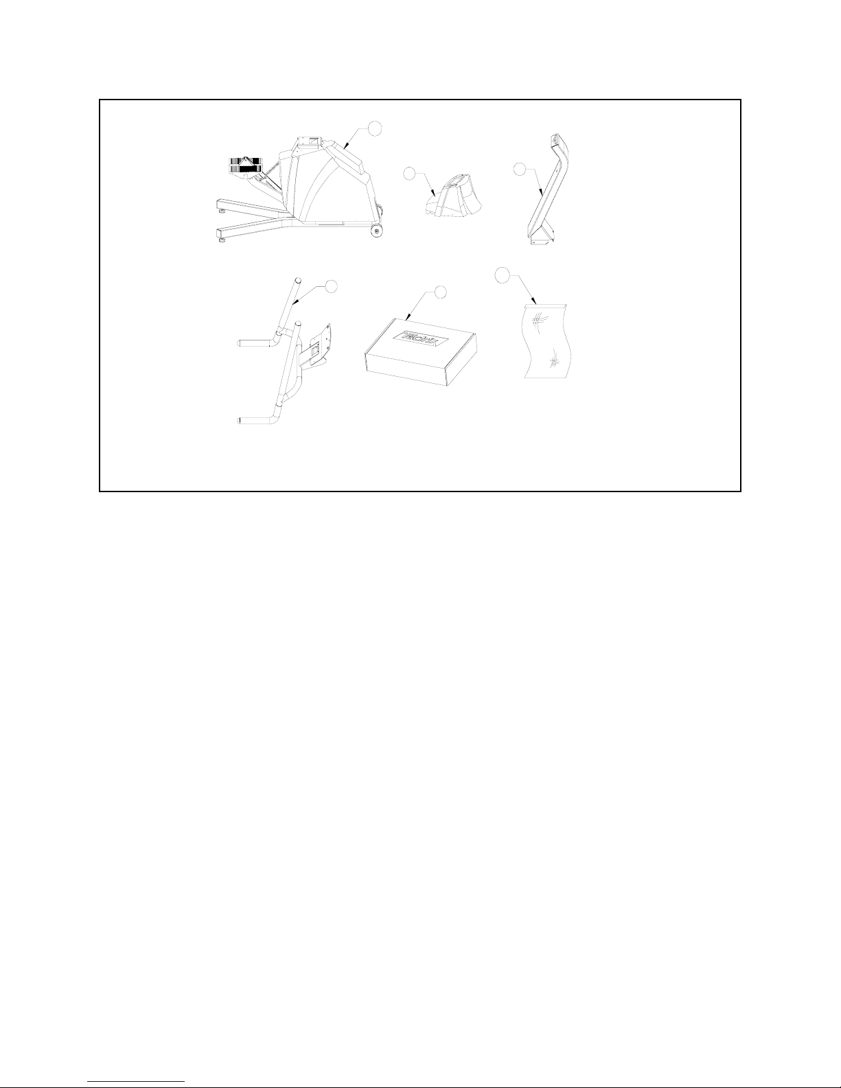
Parts Lists for the 800S Stepper
Parts that come with your 800S Stepper are shown in Figure 1 and include:
Description Qty Part Number Figure 1 Item #
Base Unit 1 70367 1
Display Upright Assembly 1 62007 2
Handrail Assembly (CT) 1 62029 3
Handrail Assembly (non CT) 1 62046 3
Collar Cover 1 30616W, 36016b & 36016G2 4
Configuration Kit 1 varies by country 5
Hardware Kit for 800S Stepper 1 71100 6
Termination Plug* 1 61026 n/a
*: The termination plug is already inserted in one of the communications sockets on the base
of the 800S Stepper.
Page 2-1
Cybex 800S Stepper Owner’s Manual
The Hardware Kit for the 800S Stepper (#71100) contains:
Part Number Qty Description
14004 1 Daisy Chain Power Cord
41109 11 #10 x 3/4" Phillips-head Screws
41076 8 5/16" x 3/4" Bolts
43042 8 5/16" Washer
The console and related materials for the 800S Stepper are packed in the configuration kit
included with the unit. This box includes the following:
Part Number Qty Description
03012 1 Service Manual
03154 1 Owner's Manual
51670 1 Water Bottle Holder
61033 1 Smart Link communications cable
Varies with country (14007 for USA) 1 Power Cord
Varies with language 1 800S Stepper Display Console
Page 2-2
3
2
4
1
5
13
Figure 1. Packaged items
Figure 1-800S Stepper Packaged Items
Cybex 800S Stepper Owner’s Manual
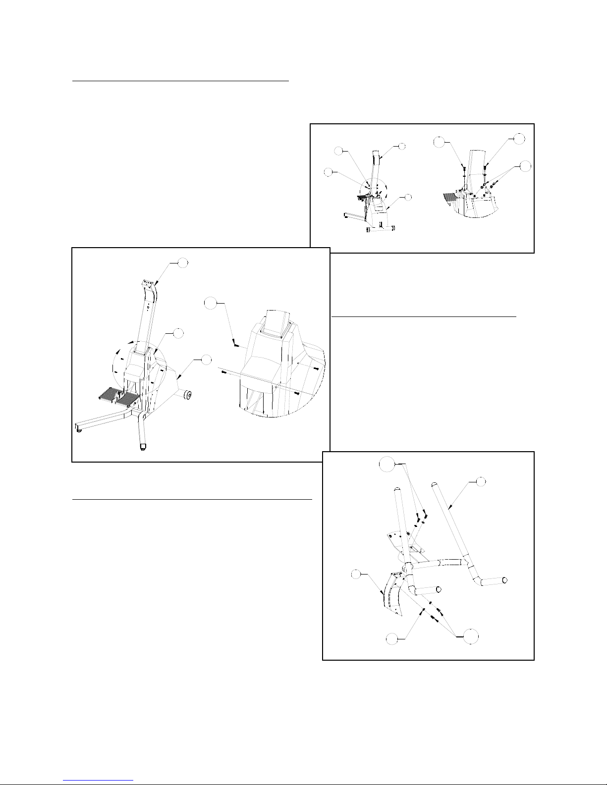
Attaching the Display Upright to the Base
Attach the display cable on the bottom of the display upright (2) to the end of the display
cable on the base frame (1). Make sure the cable connector latches snap into place.
Attach the display upright (2) to the base frame
(1) using four 5/16" screws (14) and four 5/16"
lock was hers (15). Tighten all screws by hand
first, then tighten the screws labeled 14a with a
wrench, followed by the screws labeled 14b.
See Figure 2.
Installing the Display Upright Collar
Slide the display upright collar (4) down
over the display upright (2) and attach to
the base frame cover (1) using four #10
screws (16), as shown in Figure 3.
Attaching the Handrails to the Display Upright
Place the handrails (3) on the end of the display
upright (2), as shown in Figure 4. Make sure the
handrail bracket hooks over the tab on the end of
the display upright, and the display cable passes
through the handrail bracket. This keeps the
handrails in place until the you tighten the screws.
Install the four 5/16" screws (14) and four 5/16"
lock washers (15), tightening them all by hand.
Finish tightening the screws with a wrench,
tightening the screws labeled 14a first, then those
labeled 14b.
Page 2-3
2A
14
15
2
1
DETAIL 2A
14b
14b
14a
3A
4
2
1
DETAIL 3A
16
Figure 3 - Attaching the Display Upright Collar
Figure 2 - Attaching Display Upright
14c
15
3
2
14d
Figure 4 - Attaching the Handrails
 Loading...