


Cybex 771A/771AT, 772A/772AT Arc Trainer
Owner's Manual
Part Number 5771-4 K
®
www.cybexintl.com

Cybex 771A/771AT, 772A/772AT Arc Trainer Part Number 5771-4 K
Table of Contents
Safety
Safety Guidelines and Practices.........................4
Power Cord Information......................................4
Important Safety Instructions..............................5
Warnings and Cautions......................................6
Label Placement.................................................8
Assembly
Specifications - 771A/772A..............................10
Specifications - 771AT/772AT...........................11
Choosing and Preparing Site............................12
Environment.....................................................13
Electrical Power Requirements........................13
Assembly Procedure 771A/772A......................14
Assembly Procedure 771AT/772AT..................27
Setup................................................................43
Testing Operation.............................................45
Operation
Intended Use....................................................47
Individual human power versus mechanical
power...........................................................47
Terms Used......................................................47
Console Display................................................48
User Control Symbols Used.............................49
CardioTouch Symbols Used.............................50
CardioTouch Screen and User Controls...........52
Muscle Map and Incline Meter..........................53
Mount and Dismount........................................54
Range of Motion...............................................54
Quick Operation Guide.....................................55
Detailed Operation Guide.................................56
Workout Selection............................................57
Data Readouts - LED display...........................58
E3 View Monitor Screen Options......................59
Heart Rate Indicator.........................................59
Fan Control.......................................................60
How power input versus displayed value is
calculated.....................................................60
Testing Parameters...........................................60
Maintenance
Warnings...........................................................62
Clean Unit.........................................................62
Drive Belts........................................................64
Rechargeable Battery.......................................65
E3 View Monitor................................................65
Service Schedule..............................................66
Statistics...........................................................67
Customer Service
Product Registration.........................................69
Contacting Service...........................................69
Ordering Parts..................................................69
Return Material Authorization (RMA)................70
Damaged Parts.................................................70
Appendix - Workout Overviews
Weight Loss - Hill Climb...................................71
Weight Loss - Speed Bump..............................73
Strength - High Low..........................................75
Strength - Bursts...............................................77
Strength - Interval.............................................79
Fitness (Mens) , Shaping (Womens) - Total
Leg...............................................................81
Fitness (Mens) - Target: Hip, Shaping
(Womens) - Glute Camp..............................83
Cardio - Wave...................................................85
Cardio - Interval................................................87
Cardio - Hill Interval..........................................89
Cardio - Heart Rate Control..............................91
Power - Constant Power...................................93
Power - Adaptive Power...................................94
Cybex®and the Cybex logo are registered trademarks of Cybex International, Inc. Polar®is a registered trademark of Polar Electro Inc.
DISCLAIMER: Cybex International, Inc. makes no representations or warranties regarding the contents of this manual. We reserve the right to
revise this document at any time or to make changes to the product described within it without notice or obligation to notify any person of such
revisions or changes.
©
Copyright 2016, Cybex International, Inc.
10 Trotter Drive, Medway, MA 02053 • 888-462-9239 • 508-533-4300 • FAX 508-533-5183
www.cybexintl.com • 5771-4 K • September 2016
Page 2 of 95

Cybex 771A/771AT, 772A/772AT Arc Trainer Part Number 5771-4 K
FCC Compliance Information
Changes or modifications to this unit not expressly approved by the party responsible for compliance
could void the user’s authority to operate the equipment.
This equipment has been tested and found to comply with the limits for a Class A digital device, pursuant
to part 15 of the FCC Rules. These limits are designed to provide reasonable protection against harmful
interference when the equipment is operated in a commercial environment. This equipment generates,
uses, and can radiate radio frequency energy and, if not installed and used in accordance with the
instruction manual, may cause harmful interference to radio communications. Operation of this equipment
in a residential area is likely to cause harmful interference in which case the user will be required to
correct the interference at his own expense.
Modifications not expressly approved by the manufacturer could void the user’s authority to operate the
equipment under FCC rules.
Page 3 of 95
Cybex 771A/771AT, 772A/772AT Arc Trainer Part Number 5771-4 K
Safety Guidelines and Practices
Read the Owner’s Manual carefully before assembling, servicing, or using the equipment. Owner
must comply with all safety guidelines in this manual. It is also the owner’s responsibility to instruct
users on the safe and proper operation of the equipment and to properly display any and all
warning labels and instructional placards. All users should read these labels and placards before
using equipment.
Serious injury or death could occur if the following safety precautions and
instructions are not followed.
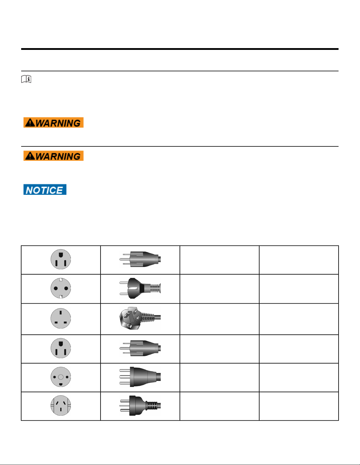
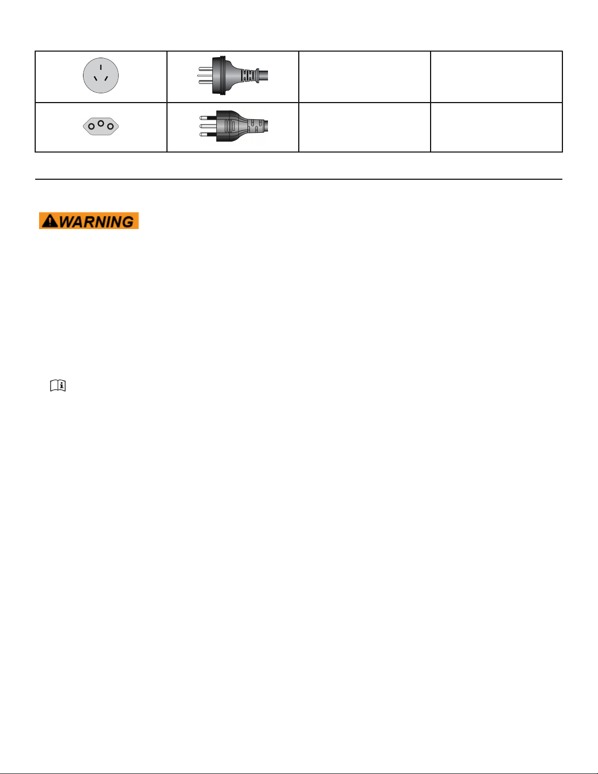
Power Cord Information
Shock and electrocution hazard.
• Connect unit to a grounded outlet.
• Do not use voltage adapter or extension cord.
Safety
Cybex is not responsible for injuries or damages as a result of cord or plug
modification.
• Verify voltage requirements of unit match local voltage requirements.
• Verify unit outlet is the same configuration as the plug.
Power cord configuration
NEMA 5-15115 VAC
CEE 7/7Euro Plug
BS 1363UK 230 VAC
JIS 8303Japanese
Page 4 of 95
107-2-D1Danish
AS/NZS 3112Australia
Cybex 771A/771AT, 772A/772AT Arc Trainer Part Number 5771-4 K
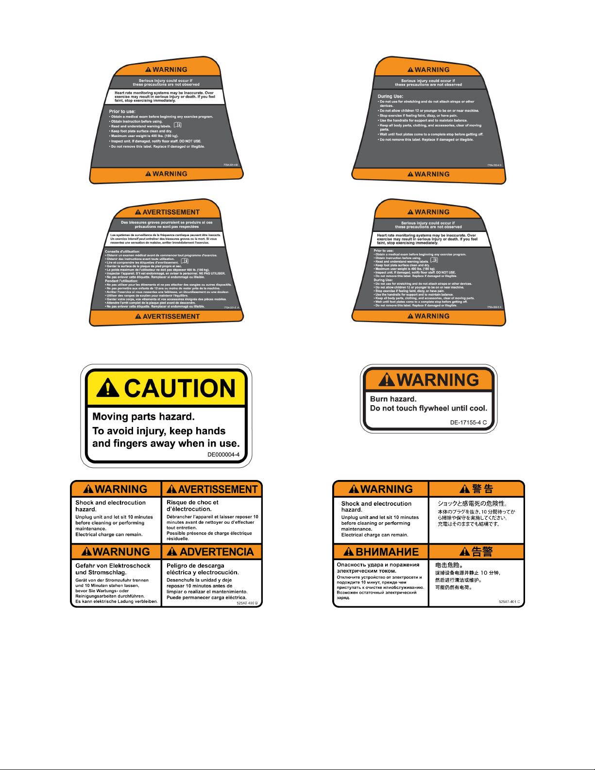
Important Safety Instructions
(Save These Instructions)
Shock and electrocution hazard.
• Unplug unit and let sit 10 minutes before cleaning or performing
maintenance.
• Electrical charge can remain in unit after unplugging.
• Keep water and liquids away from electrical parts.
User Safety Precautions
Prior to use:
Chinese
GB 2099-1 and GB
1002-1
IEC-60320-C13Brazil
• Obtain a medical exam before beginning any exercise program.
• Obtain instruction before using.
•
Read and understand warning labels.
• Keep foot plate surface clean and dry.
• Maximum user weight is 400 lbs. (180 kg).
• Inspect unit. If damaged, notify floor staff. DO NOT USE.
• Do not remove this label. Replace if damaged or illegible.
During use
• Do not use for stretching and do not attach straps or other devices.
• Do not allow children 12 or younger to be on or near machine.
• Stop exercise if feeling faint, dizzy, or have pain.
• Use the handrails for support and to maintain balance.
• Keep all body parts, clothing, and accessories, clear of moving parts.
• Wait until foot plates come to a complete stop before getting off.
Facility Safety Precautions
It is the sole responsibility of the user/owner or facility operator to ensure that regular maintenance is
performed.
• Enforce all user and safety precautions.
• Read and understand the Owner’s Manual completely before assembling, servicing or using unit.
• Verify all users are properly trained on using the equipment.
• Do not use unit outdoors.
Page 5 of 95

Cybex 771A/771AT, 772A/772AT Arc Trainer Part Number 5771-4 K
• Verify that each unit is setup, leveled and operated on a solid level surface. Do not install equipment
on an uneven surface.
• Verify there is enough room for safe access and operation of unit.
• Use Cybex AC power adapters only.
• Do not use the optional power adapter in damp or wet locations.
• Do not use the unit if: (1) the unit is plugged into an optional power adapter that has a damaged cord;
(2) the unit is not working properly or (3) if the unit has been dropped or damaged. Seek service from
a qualified technician.
• EQUIPMENT is not suitable for use in the presence of aerosol (spray), FLAMMABLE ANAESTHETIC
MIXTURE WITH AIR or WITH OXYGEN or NITROUS OXIDE.
• Perform regular maintenance checks on unit. Performance level can be maintained only if examined
regularly. Pay close attention to all areas most susceptible to wear, including (but not limited to)
cables, pulleys, belts and grips.
• Replace any warning labels if damaged, worn, or illegible.
• Immediately replace worn or damaged components. If unable to immediately replace worn or damaged
components, then remove unit from service until repair is made.
• Do not attempt electrical or mechanical repairs.
Seek qualified repair personnel when servicing. If you live in the USA, contact Cybex Customer
Service at 888-462-9239. If you live outside the USA, contact Cybex Customer Service at
508-533-4300.
• Use only Cybex supplied components to maintain/repair unit.
• Keep a repair log of all maintenance activities.
• Disconnect the optional power adapter before servicing unit.
• Do not use attachments unless recommended for the unit by Cybex.
• The unit may generate electromagnetic or other forms of interference, or it may be affected by
interference from other equipment nearby. If this is suspected, take precautions by separating the
equipment or otherwise shielding it to avoid such interference.
Warnings and Cautions
Warning labels indicate a potentially hazardous situation that could result in serious injury or death if
the precautions are not observed.
Caution labels indicate a potentially hazardous situation that could result in serious injury or damage to
machine if the precautions are not observed.
Contact Cybex Customer Service to replace any worn or damaged labels.
Page 6 of 95
Cybex 771A/771AT, 772A/772AT Arc Trainer Part Number 5771-4 K
Canadian
Page 7 of 95
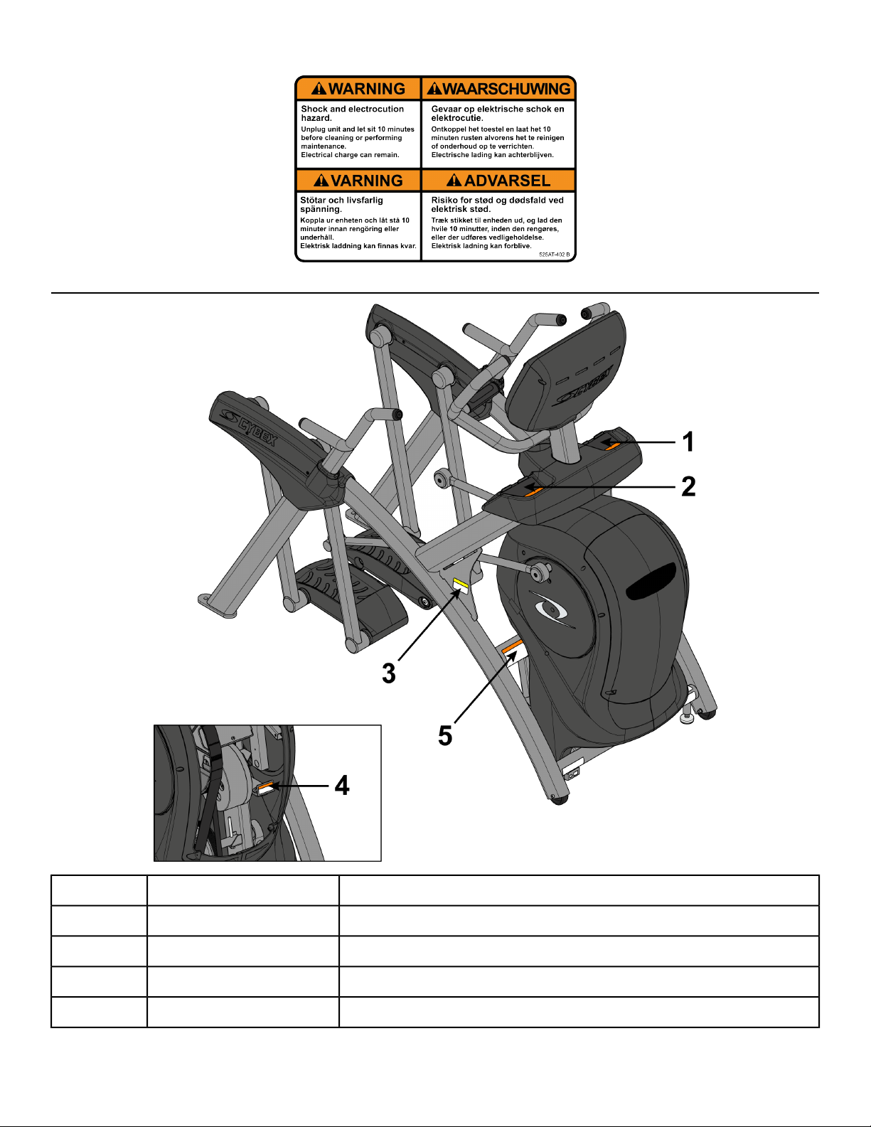
Label Placement
Cybex 771A/771AT, 772A/772AT Arc Trainer Part Number 5771-4 K
Label, Warning, Access tray, Left770A-331-X1
Label, Warning, Access tray, Left, Canadian770A-331-E1
Label, Warning, Access tray, Right770A-332-X2
Label, Warning, Access tray, Right, Canadian770A-332-E2
Decal, Caution moving partsDE000004-X3
Page 8 of 95

Cybex 771A/771AT, 772A/772AT Arc Trainer Part Number 5771-4 K
Label, Warning, Hot flywheelDE-17155-X4
Label, Warning, Disconnect Power525AT-4005
Label, Warning, Disconnect Power525AT-4015
Label, Warning, Disconnect Power525AT-4025
Label, Warning, Disconnect Power525AT-4185
Page 9 of 95

Cybex 771A/771AT, 772A/772AT Arc Trainer Part Number 5771-4 K
Specifications - 771A/772A
S (Studio)Classification
AAccuracy
76.25” (194 cm)Assembled Length
32” (81 cm)Assembled Width
62.5”(159 cm)Assembled Height
404 lbs (183 kg)Weight of Product
429 lbs (195 kg)Shipping Weight
0-20 % gradeIncline Levels
0-100Resistance Levels
Assembly
Workouts
Console Features
Heart Rate Features
Options
24” (61 cm) fixed lengthStride Length
Quick Start, five workout groups, seven workouts, four heart rate workouts,
and two power workouts
Upper console: LED or E3 View Monitor. Displays Cal/Hr, Distance,
Strides per Minute, Calories, Watts, METs and BPM. Lower console: Two
numeric displays for incline, time, resistance and level. Fan, CardioTouch
screen, accessory trays and water bottle holder.
Built-in 5 KHz wireless heart rate receiver (transmitter not included) and
contact heart rate monitoring.
0 to 900 watts.Resistance Range
400 lbs. (180 kg).Maximum User Weight
Self powered or 100 - 240 VAC~, 50/60 Hz, 1.8A, 1-phase.Power Rating
AC Power Adapter, Set Top Box wiring (to support CAB and MYE using
Coax or HDMI).
Page 10 of 95
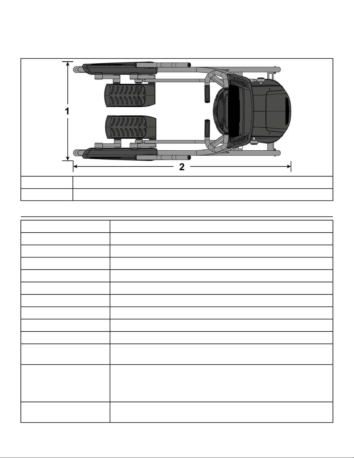
Top View 771A/772A
Dimensions
Cybex 771A/771AT, 772A/772AT Arc Trainer Part Number 5771-4 K
1
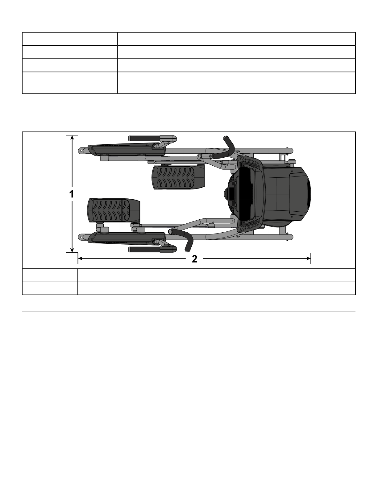
Specifications - 771AT/772AT
S (Studio)Classification
AAccuracy
76.25” (194 cm)Assembled Length
36.28” (92 cm)Assembled Width
62.5”(159 cm)Assembled Height
412 lbs. (187 kg.)Weight of Product
437 lbs. (198 kg.)Shipping Weight
0-20 % gradeIncline Levels
0-100Resistance Levels
24” (61 cm) fixed lengthStride Length
32” (81 cm)
62.5” (159 cm)2
Workouts
Console Features
Heart Rate Features
Quick Start, five workout groups, seven workouts, four heart rate workouts,
and two power workouts
Upper console: LED or E3 View Monitor. Displays Cal/Hr, Distance,
Strides per Minute, Calories, Watts, METs and BPM. Lower console: Two
numeric displays for incline, time, resistance and level. Fan, CardioTouch
screen, accessory trays and water bottle holder.
Built-in 5 KHz wireless heart rate receiver (transmitter not included) and
contact heart rate monitoring.
Page 11 of 95
Cybex 771A/771AT, 772A/772AT Arc Trainer Part Number 5771-4 K
0 to 900 watts.Resistance Range
400 lbs. (180 kg).Maximum User Weight
Self powered or 100 - 240 VAC~, 50/60 Hz, 1.8A, 1-phase.Power Rating
Options
Top View 771AT/772AT
Dimensions
AC Power Adapter, Set Top Box wiring (to support CAB and MYE using
Coax or HDMI).
1
36.28” (92 cm)
76.25” (194 cm)2
Choosing and Preparing Site
Before assembling the unit, verify the chosen site meets the following criteria:
• Area is well lit and well ventilated.
• Surface is structurally sound and properly leveled.
• Free area for access to unit and emergency dismount. Minimum clearance is 23.6 inches (0.6 meters).
• Adjacent units may share the free area.
Page 12 of 95
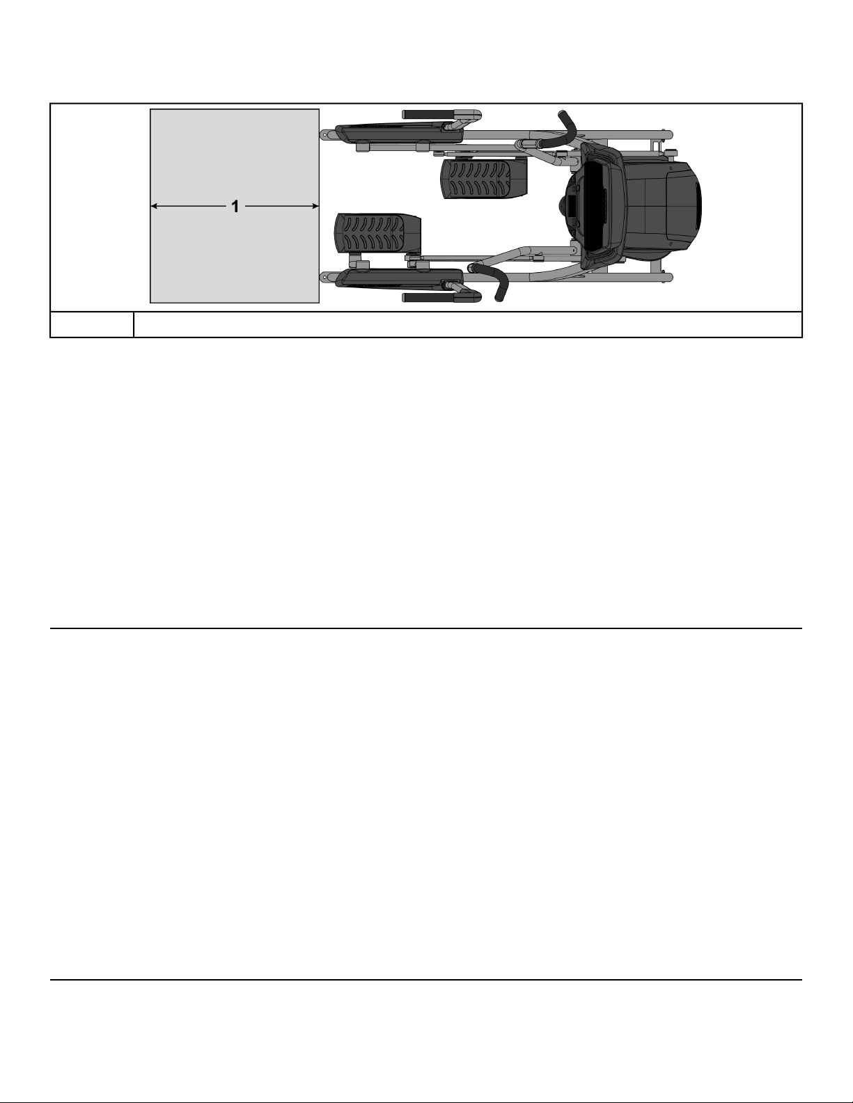
Free Area
Cybex 771A/771AT, 772A/772AT Arc Trainer Part Number 5771-4 K
1
It is the responsibility of the facility owner/owner of the equipment to ensure that there is appropriate
clearance around each machine to allow for safe use and passage.
In compliance with the ADA (American Disabilities Act) there must be clear floor space of at least 30 by
48 inches and be served by an accessible route for at least one of each type of exercise equipment. If
the clear space is enclosed on three sides (e.g., by walls or the equipment itself), the clear space must
be 36 by 48 inches.
All other machines must have a clear floor space of 23" for all access point on the machine.
The dimensions stated in the assembly instructions of this manual include the maximum foot print (in
use) dimensions.
Minimum clearance of 12” (30 cm) between units for proper wireless heart rate signal operation.
23.6”, 0.6m
Environment
Humidity and Static Electricity
The unit is designed to function normally in an environment with a relative humidity range of 30% to
75%. The unit can be shipped and stored in a relative humidity range of 10% to 90%.
Climatic dry air may cause static electricity. During workout, user may experience a shock due to build
up of static electricity on the body and the discharge path of the unit. If static electricity is experienced,
increase humidity to a comfortable level through the use of a humidifier.
Do not install, use or store the unit in an area of high humidity, such as in the vicinity of a steam room,
sauna, indoor pool or outdoors. Exposure to extensive water vapor, chlorine and/or bromine could
adversely affect the electronics as well as other parts of the unit.
Temperature
The unit is designed to function normally in an environment with an ambient temperature range of 50°
F (10° C) to 104° F (40° C). The unit can be shipped and stored in an environment with an ambient
temperature range of 32° F (0° C) to 140° F (60° C).
Electrical Power Requirements
The AC power kit is optional.
Page 13 of 95
Cybex 771A/771AT, 772A/772AT Arc Trainer Part Number 5771-4 K
The E3 View Monitor is supplied with a power cord,
Use Cybex supplied AC power kit only. Consult an electrician with any questions.
Verify the unit is connected to an outlet having the same configuration as the plug.
Verify connection is a grounded circuit. Do not use a ground-plug adapter to adapt the 3-prong power
cord to a non-grounded electrical outlet.
Verify power supply is compliant with local building codes.
Assembly Procedure 771A/772A
Two people will be required for this procedure.
Read and understand all instructions thoroughly before assembling this unit. Check all items
carefully. If there is damage, see the Customer Service section of this manual for proper procedure
to return, replace, or reorder parts.
The words "left" and "right" denote the user's orientation.
Verify you have received the correct package
1. Read box label to verify the model number and voltage (optional) match what was ordered.
2. Verify paint color matches what was ordered.
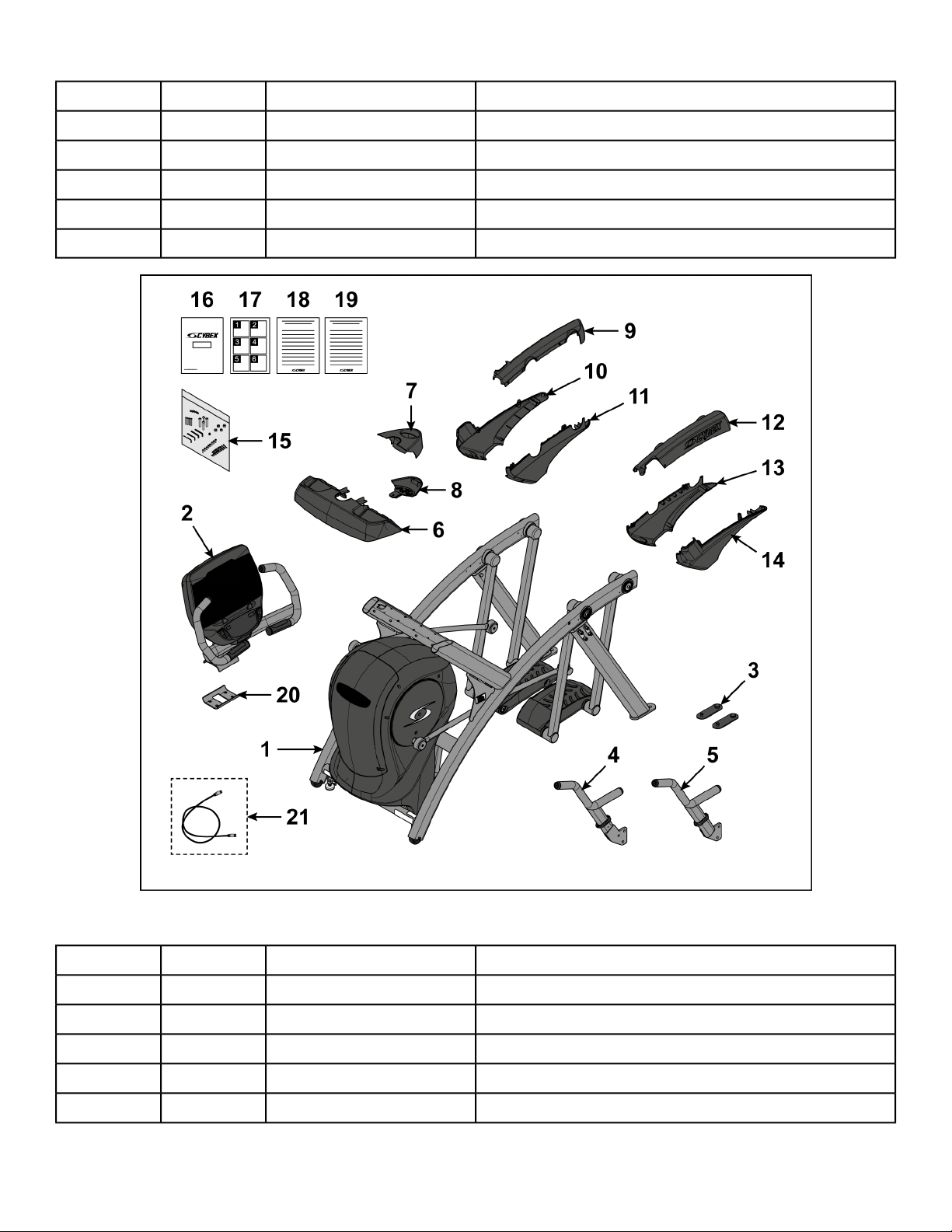
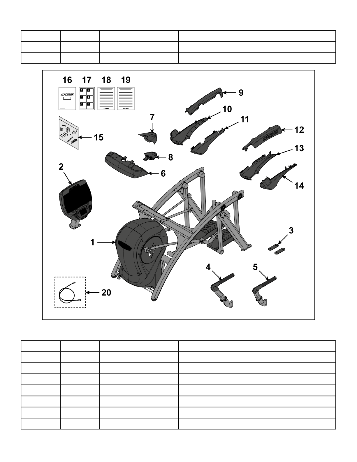
Verify parts list shown below
DescriptionPart NumberQuantityItem
Base assemblyVaries11
Console assemblyVaries12
Foot pad12090-32223
Handle, Right-14
Handle, Left-15
Base, Accessory tray770A-31616
Cover, Top, Accessory tray770A-31717
Cover, Bottom, Accessory tray770A-31818
Cover, Rear, Top, Right770A-32219
Cover, Rear, Outer, Right770A-323110
Cover, Rear, Inner, Right770A-324111
Cover, Rear, Top, Left770A-319112
Cover, Rear, Inner, Left770A-321113
Cover, Rear, Outer, Left770A-320114
Hardware pack-115
Owner’s Manual5771-X116
Page 14 of 95
Cybex 771A/771AT, 772A/772AT Arc Trainer Part Number 5771-4 K
DescriptionPart NumberQuantityItem
Assembly poster771A-404117
Commercial Arc warranty sheet770A-415118
Consumer Arc warranty sheet770A-416119
Bracket, Lower, Display mount770A-310120
Cable, 6’, Coax (E3 View Monitor option)770A-427121
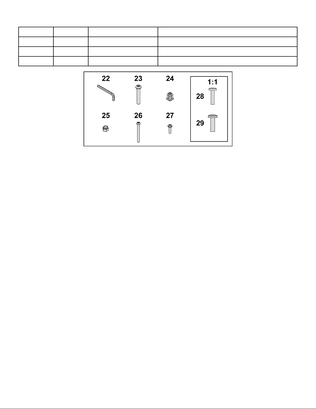
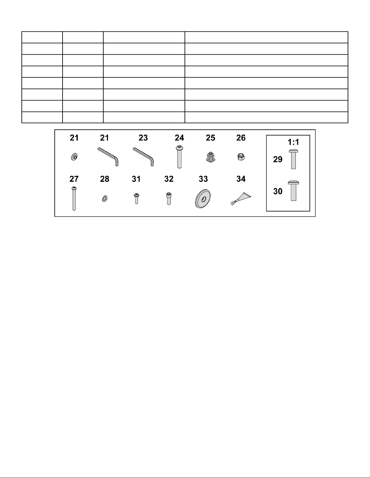
Hardware
DescriptionPart NumberQuantityItem
7/32” Allen WrenchBK030204122
BHSCS .375-16 × 2.50”HC700430423
Grommet, NylonHF540200124
Locknut, .375-16 NylonHN704901425
Tap Sc 10-12 × 2.00 Pn Hd PhilHT592526426
Page 15 of 95
Cybex 771A/771AT, 772A/772AT Arc Trainer Part Number 5771-4 K
DescriptionPart NumberQuantityItem
Screw, Pan Head Phillips, #6 × .50”HT532512227
Screw, Pan Head Phillips, 8-16 × .50”HT5525121928
Screw, Pan Head Phillips, 10-24 × .75”HT572515829
Page 16 of 95
Cybex 771A/771AT, 772A/772AT Arc Trainer Part Number 5771-4 K
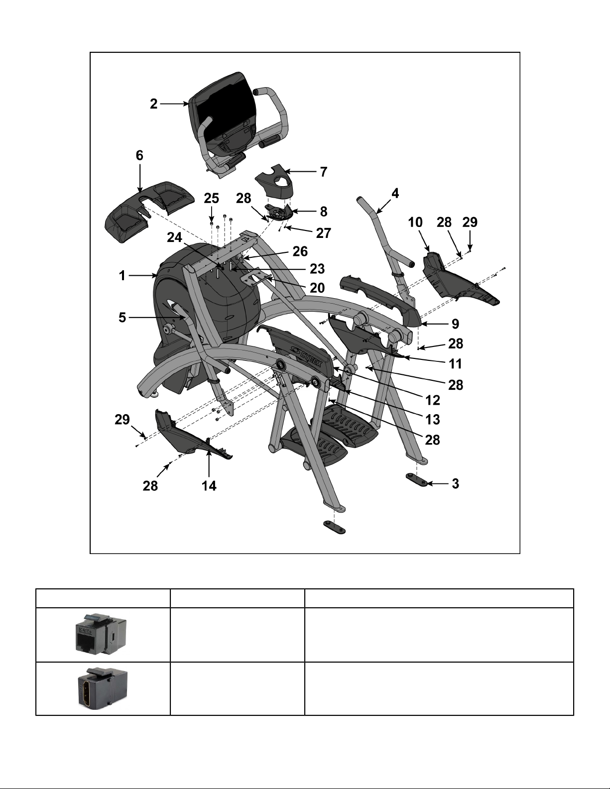
Optional audio visual components
DescriptionPart NumberCoupler
Ethernet CouplerOCN-22747
HDMI CouplerOCN-25816
Page 17 of 95
Cybex 771A/771AT, 772A/772AT Arc Trainer Part Number 5771-4 K
Tools Required
• Phillips screwdriver
• Stubby Phillips screwdriver
• 3/16” Allen wrench (included)
• 7/32” Allen wrench (included)
• 9/16” Open end wrench (2)
Lift and move unit
1. Remove large bolts and shipping supports. Keep package material on linkage arms at this time.
This will protect the paint from scratching during assembly.
2. Grasp each rear support leg firmly and lift with one person on each side.
3. Lift the lower rear support legs so the front transport wheels are able to roll on floor.
Use proper lifting methods.
4. Move unit to intended location.
5. Lower rear support legs.
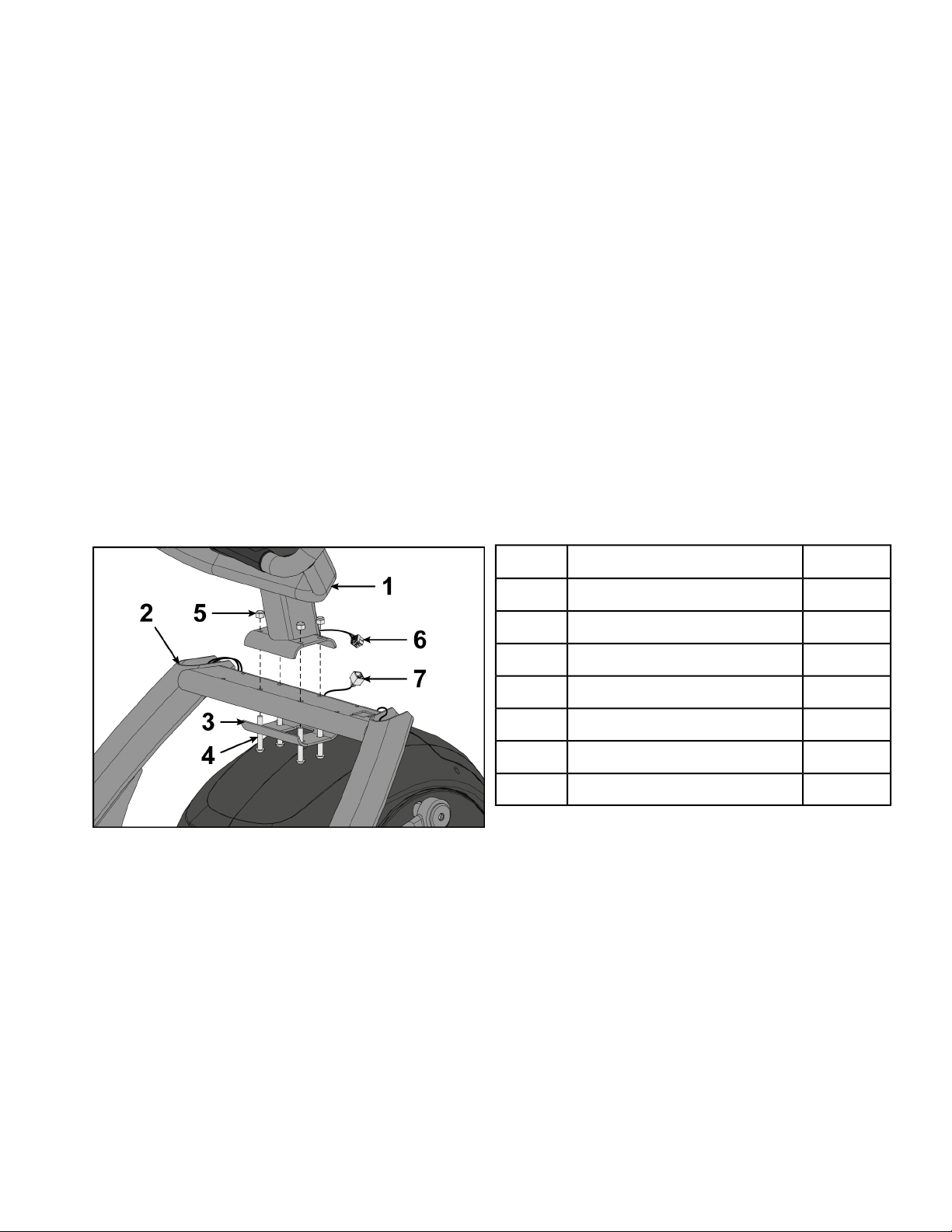
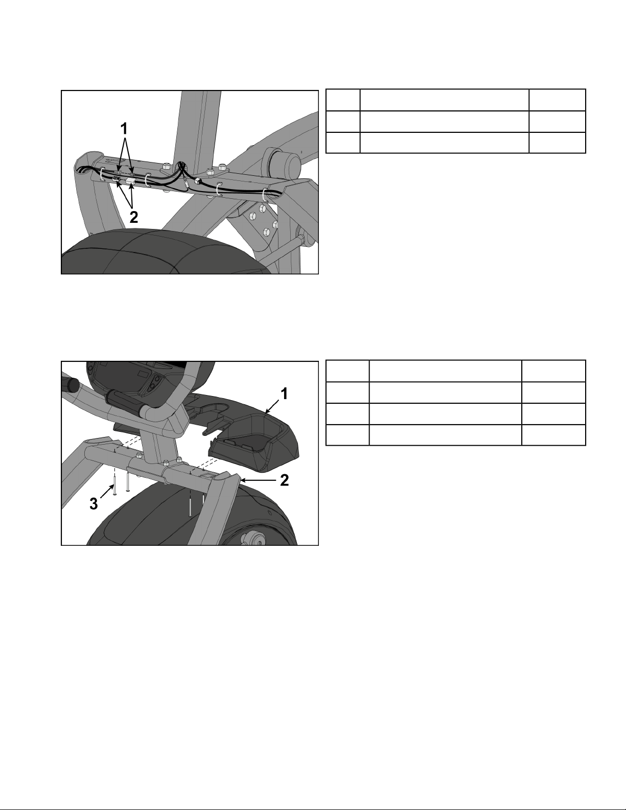
Install console assembly
1. Place the console into position on the frame. Do not pinch cables while lowering the console.
QtyDescription
2. Insert (from underneath) the lower bracket and four bolts into the frame and console.
3. Thread the four locknuts onto the bolts by hand.
4. Tighten the four bolts and locknuts with a 7/32” Allen wrench and a 9/16” open-end wrench.
5. Plug the upper display cable into the lower display cable.
1Console1
1Frame2
1Lower bracket3
4Bolts4
4Locknuts5
1Upper display cable6
1Lower display cable7
Page 18 of 95
Cybex 771A/771AT, 772A/772AT Arc Trainer Part Number 5771-4 K
Install optional coax and ethernet cables
1. Plug the coax cable connectors into each other and tighten threaded connector.
2. Plug the ethernet cable connectors into each other.
Qty.Description
1Coax cable connectors1
1Ethernet cable connectors2
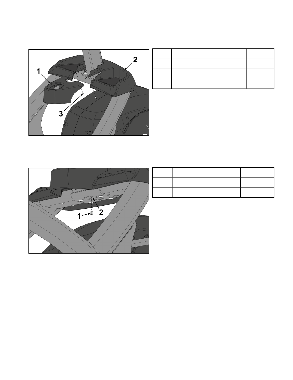
Install accessory tray base
Install the four screws securing accessory tray base to frame using a stubby Phillips screwdriver.
QtyDescription
1Accessory tray base1
1Frame2
4Screws3
Page 19 of 95
Cybex 771A/771AT, 772A/772AT Arc Trainer Part Number 5771-4 K
Install accessory tray top
Install the two screws securing accessory tray top to accessory tray base using a stubby Phillips
screwdriver.
QtyDescription
1Accessory tray top1
1Accessory tray base2
2Screws3
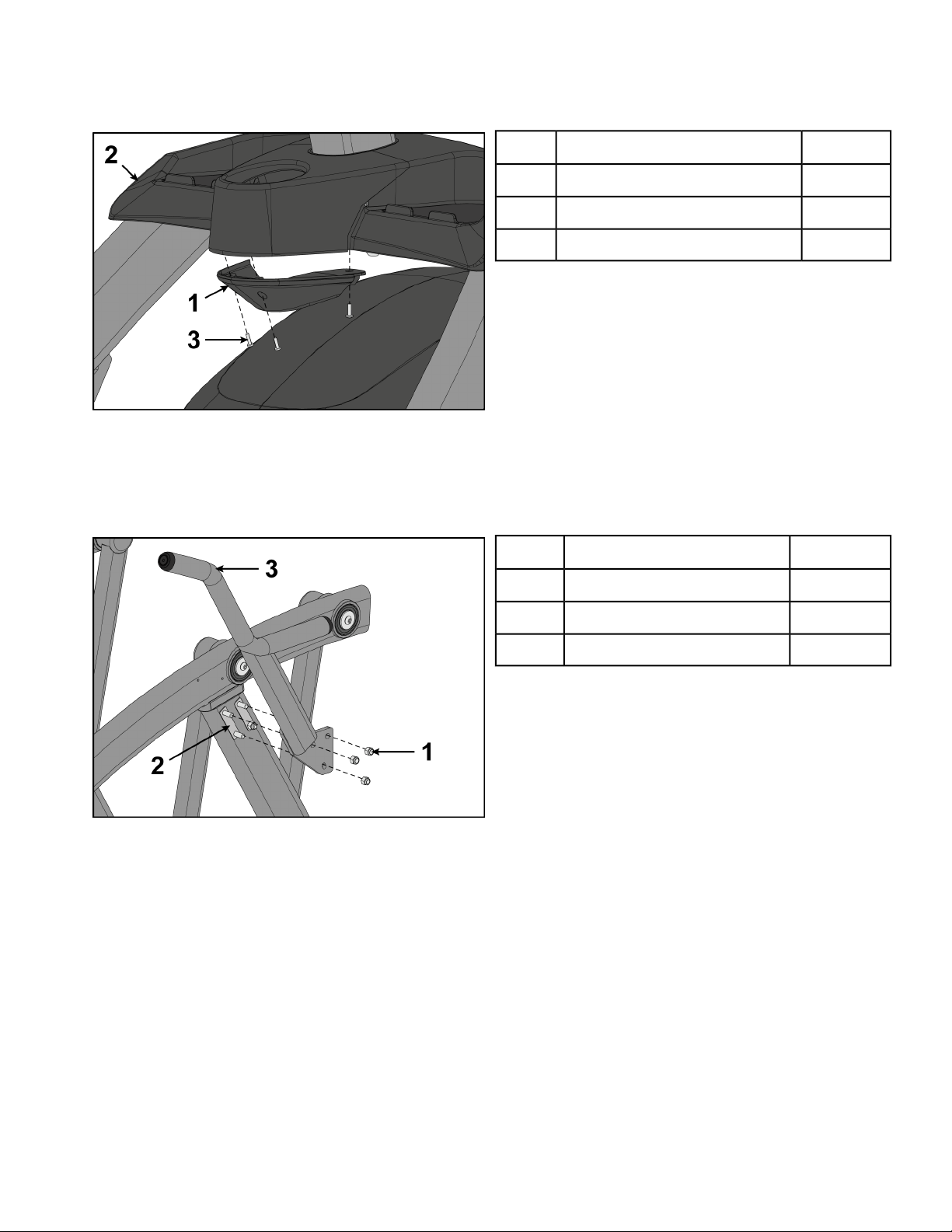
Install accessory tray bottom
1. Install the grommet to the frame.
QtyDescription
1Grommet1
1Frame2
Page 20 of 95
Cybex 771A/771AT, 772A/772AT Arc Trainer Part Number 5771-4 K
2. Install the accessory tray bottom to the accessory tray base with three screws using a Phillips
screwdriver.
QtyDescription
1Accessory tray bottom1
1Accessory tray base2
3Screws3
Install handrails
1. Remove three locknuts from the left support leg using two 9/16" open end wrenches. Keep the two
spacers in place.
QtyDescription
3Locknuts1
2Spacers2
1Left handle3
2. Install the left handle and three locknuts using two 9/16" open end wrenches.
Page 21 of 95
Cybex 771A/771AT, 772A/772AT Arc Trainer Part Number 5771-4 K
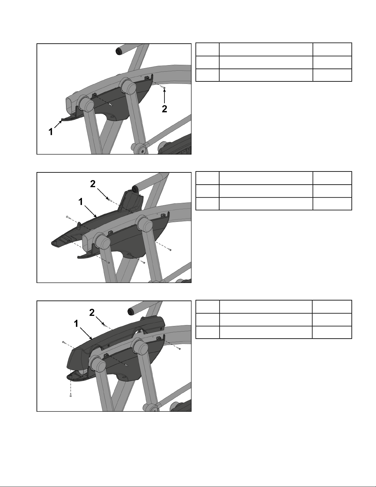
3. Install the left inner rear cover with two screws using a Phillips screwdriver.
4. Install the left outer rear cover with five screws using a Phillips screwdriver.
QtyDescription
1Left inner rear cover1
2Screws2
QtyDescription
1Left outer rear cover1
5. Install the left top rear cover with five screws using a Phillips screwdriver.
5Screws2
QtyDescription
1Left top rear cover1
5Screws2
Page 22 of 95
Cybex 771A/771AT, 772A/772AT Arc Trainer Part Number 5771-4 K
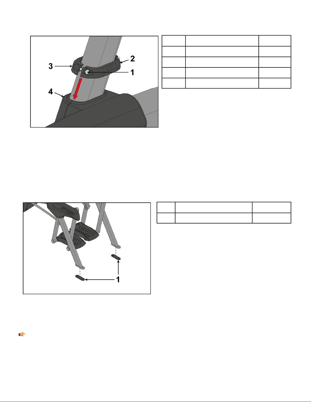
6. Loosen the two screws in the left inner and outer collars using a Phillips screwdriver.
7. Slide the inner and outer collars onto the left cover.
8. Insert the tabs of the collars into the slots of the cover.
9. Tighten the two screws using a Phillips screwdriver.
QtyDescription
2Screws1
1Inner collar2
1Outer collar3
1Cover4
10. Repeat steps 1 through 9 for the right side.
Install foot pads
Have one person lift the unit while a second person places a foot pad under each of the two back feet.
Qty.Description
2Foot pads1
Level unit
This procedure will level the unit by evenly adjusting the weight on the rear feet. Leveling the unit will
eliminate rocking during use.
Note: References to left and right are from the users perspective during use.
1. Verify foot plates are completely stopped.
Page 23 of 95
Cybex 771A/771AT, 772A/772AT Arc Trainer Part Number 5771-4 K
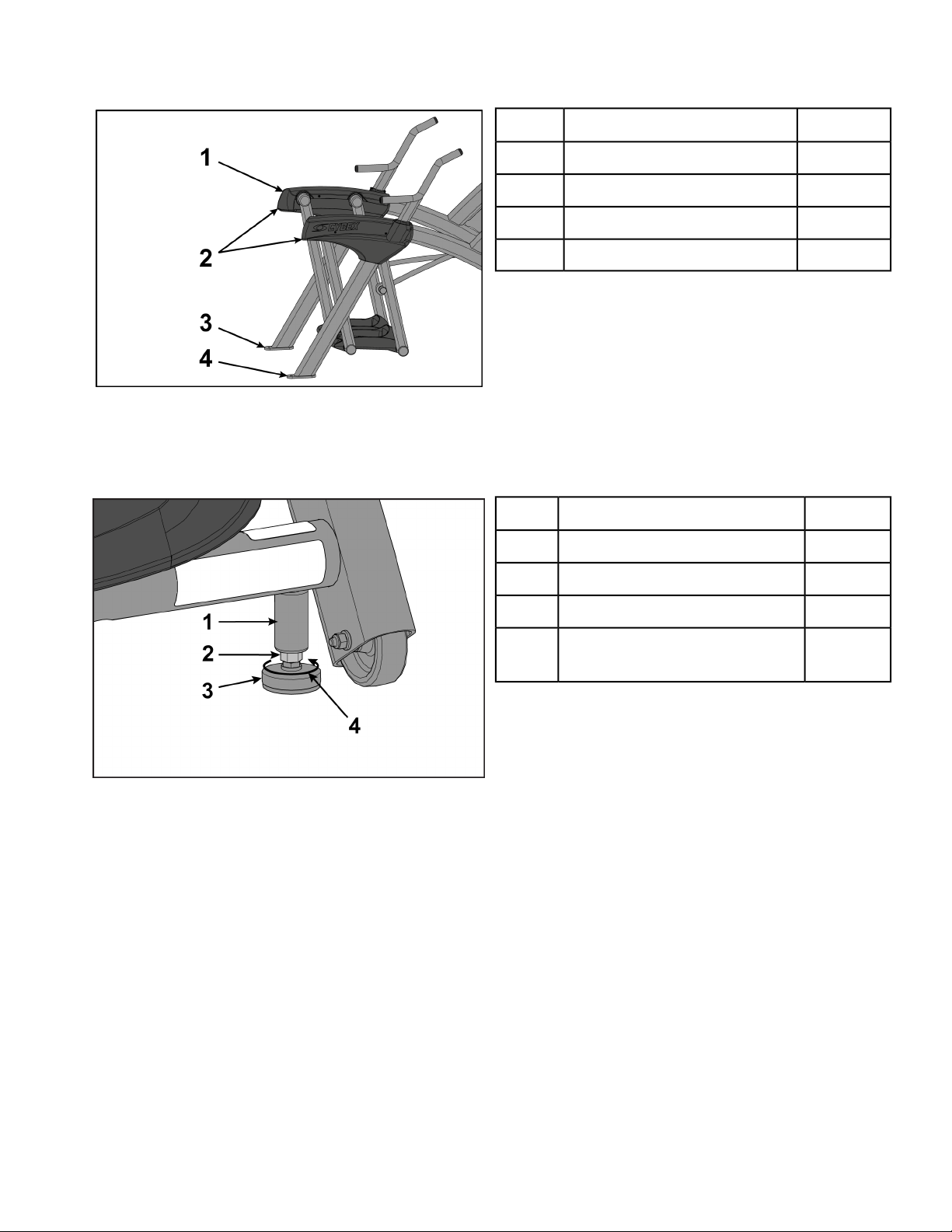
2. Grasp one of the rear covers and slowly lift the rear foot off the floor. Lower rear foot to the floor.
Qty.Description
2Rear cover1
2Lift here2
1Left rear foot3
1Right rear foot4
3. Grasp the other rear cover and slowly lift the rear foot off the floor. Lower rear foot to the floor.
Make note of either rear foot lifting off the floor easier than the other.
If both rear feet lift off the floor evenly, secure both leveling foot jam nuts against the frame post
using a 9/16” open-end wrench. Unit is leveled.
Left leveling foot shown
Qty.Description
1Frame post1
1Jam nut2
1Leveling foot3
4
Turn counter-clockwise to
secure
1
Page 24 of 95
Cybex 771A/771AT, 772A/772AT Arc Trainer Part Number 5771-4 K
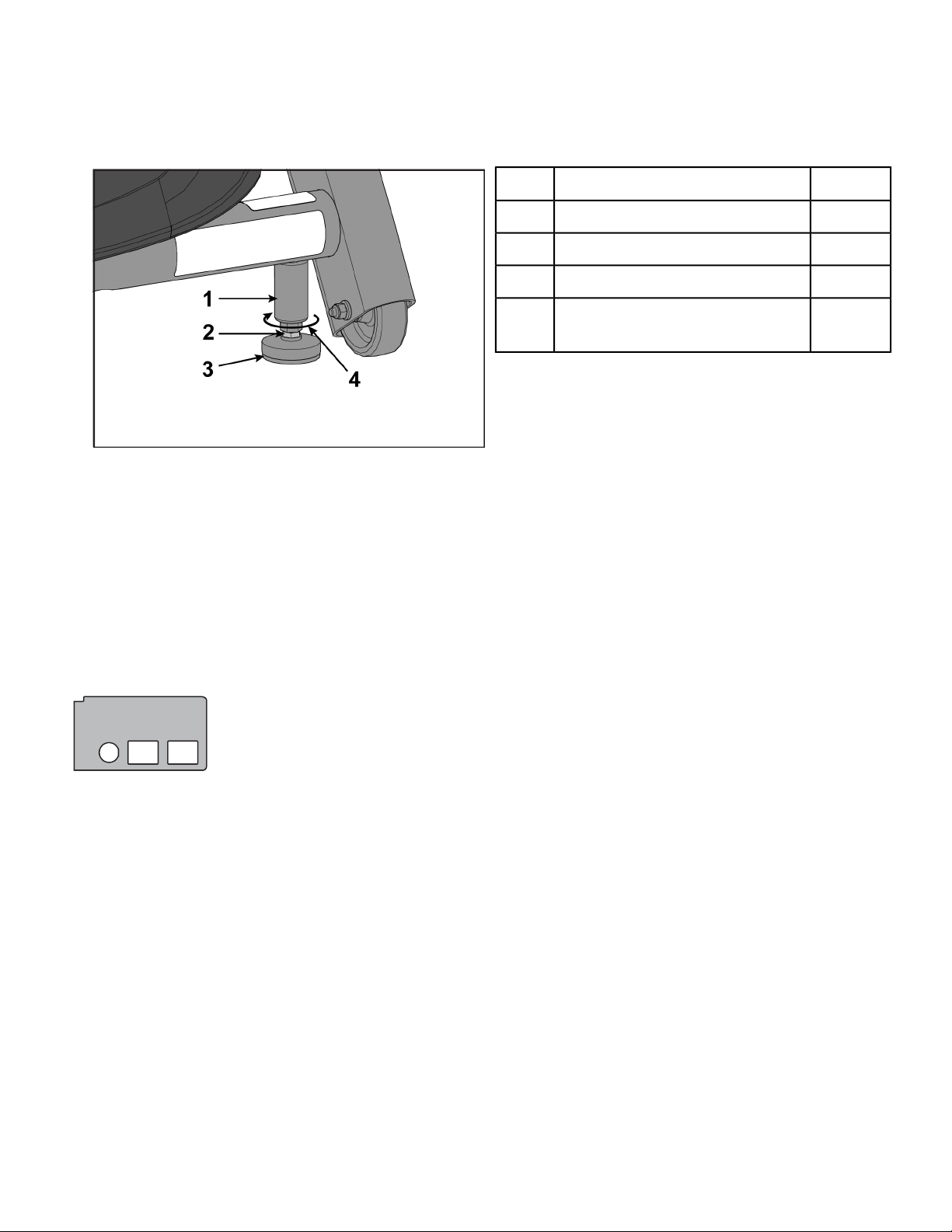
4. Adjust the weight of the rear feet using a 1/2” open-end wrench.
• If the left rear foot lifts up easier, Adjust the right leveling foot nut down.
• If the right rear foot lifts up easier, Adjust the left leveling foot nut down.
Qty.Description
1Frame post1
1Leveling foot nut2
1Leveling foot3
Turn clockwise to adjust level-
4
ing foot down
1
Left leveling foot shown
5. Test the unit again for uneven weight on the rear feet. Adjust leveling foot nuts until each rear foot
lifts with even force.
6. Secure both jam nuts using a 9/16” open-end wrench. Unit is leveled.
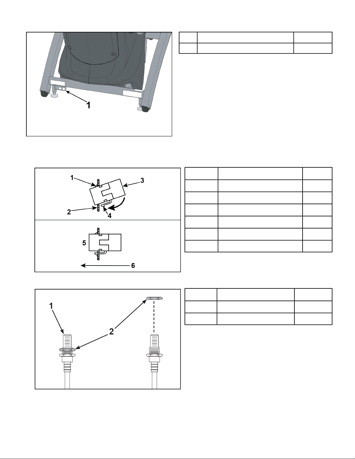
Install optional Audio Visual cables
The optional audio visual cables can include combinations of Coax, Ethernet, or HDMI cables.Mounting
plate has three holes for all configuration options:
• Coax Only (EPEM Tuner or MYE CableSAT w/coax)
• Coax and Ethernet (Cybex GO or BV CAB w/coax)
• Ethernet Only (BV CAB TV on a stand)
• HDMI Only (MYE CableSAT w/HDMI)
• Ethernet and HDMI (BV CAB)
Page 25 of 95
Cybex 771A/771AT, 772A/772AT Arc Trainer Part Number 5771-4 K
Qty.Description
1Mounting plate location1
1. Insert the optional couplers into the mounting plate by hooking the upper tab into the mounting plate
and snapping in the lower tab.
Qty.Description
2. Remove the nut at the end of the coax cable.
1Upper tab1
1Mounting plate2
1Ethernet or HDMI coupler3
1Lower tab4
1Installed5
1Front of unit6
Qty.Description
1Coax cable1
1Nut2
3. Insert the coax cable into the D-shaped hole in the mounting plate on the front of the unit.
4. Thread the nut removed in step 2 onto the coax cable.
Page 26 of 95
Cybex 771A/771AT, 772A/772AT Arc Trainer Part Number 5771-4 K
5. Install the coax cable to the mounting plate on the front of the unit using a 14 mm open end wrench.
6. Plug the Ethernet or HDMI cable into the coupler on the front of the unit.
Visually inspect unit
1. Remove any packing material from unit.
2. Examine the unit to ensure that the assembly is correct and complete.
Assembly Procedure 771AT/772AT
Two people will be required for this procedure.
Read and understand all instructions thoroughly before assembling this unit. Check all items
carefully. If there is damage, see the Customer Service section of this manual for proper procedure
to return, replace, or reorder parts.
The words "left" and "right" denote the user's orientation.
Verify you have received the correct package
1. Read box label to verify the model number and voltage (optional) match what was ordered.
2. Verify paint color matches what was ordered.
Verify parts list shown below
DescriptionPart NumberQuantityItem
Base assemblyVaries11
Console assemblyVaries12
Foot pad12090-32223
Handle, RightNA14
Handle, LeftNA15
Base, Accessory tray770A-31616
Cover, Top, Accessory tray770A-31717
Cover, Bottom, Accessory tray770A-31818
Cover, Rear, Top, Right770A-32219
Cover, Rear, Outer, Right770A-323110
Cover, Rear, Inner, Right770A-324111
Cover, Rear, Top, Left770A-319112
Cover, Rear, Inner, Left770A-321113
Cover, Rear, Outer, Left770A-320114
Hardware packNA115
Owner’s Manual5771-X116
Assembly poster771AT-316117
Commercial Arc warranty sheet770A-415118
Page 27 of 95
Cybex 771A/771AT, 772A/772AT Arc Trainer Part Number 5771-4 K
DescriptionPart NumberQuantityItem
Consumer Arc warranty sheet770A-416119
Cable, 6’, Coax (E3 View Monitor option)770A-427120
Hardware
DescriptionPart NumberQuantityItem
Flange Spacer600A-311221
3/16” Allen WrenchBK030201122
7/32” Allen WrenchBK030204223
BHSCS .375-16 × 2.25”HC700428424
Grommet, NylonHF540200125
Locknut, .375-16 NylonHN704901426
Tap Sc 10-12 × 2.00 Pn Hd PhilHT592526427
Page 28 of 95
Cybex 771A/771AT, 772A/772AT Arc Trainer Part Number 5771-4 K
DescriptionPart NumberQuantityItem
Washer, Flat .281 ID × .500 OD × .062”HS307601228
Screw, Pan Head Phillips, #6 × .50”HT532512229
Screw, Pan Head Phillips, 8-16 × .50”HT5525121930
Screw, Pan Head Phillips, 10-24 × .75”HT572515831
SHCS .250-20 UNC-3A SSHX622815232
Linkage Rod Cap 2.00 OD (1 extra)PL-16535333
LoctiteYA000201134
Page 29 of 95
 Loading...