

Page 1

Cybex Treadmill
Product Number 751T
Owner’s Manual
Cardiovascular Systems
Part Number LT-20406-4 K
www.cybexintl.com
Page 2

Page 3

Cybex Treadmill
Product Number 751T
Owner’s Manual
Cardiovascular Systems
Part Number LT-20406-4 K
Cybex® and the Cybex logo are registered trademarks of Cybex International, Inc. Safety Sentry™ is a registered trademark of Cybex
International, Inc. Polar® is a registered trademark of Polar Electro Inc.
DISCLAIMER: Cybex International, Inc. makes no representations or warranties regarding the contents of this manual. We reserve the right to
revise this document at any time or to make changes to the product described within it without notice or obligation to notify any person of such
revisions or changes.
© 2011, Cybex International, Inc. All rights reserved. Printed in United States of America.
10 Trotter Drive Medway, MA 02053 • 888-462-9239 • 508-533-4300 • FAX 508-533-5183
www.cybexintl.com • techhelp@cybexintl.com • LT-20406-4 K
Page 4

Page 5

Cybex 751T Treadmill Owner’s Manual
Table of Contents
FCC Compliance Information ..........7
Safety
Important Voltage Information..........9
Grounding Instructions ............... 9
Important Safety Instructions .........10
Warning Decals....................13
Caution Decals ....................14
Emergency Stop Key (e-stop).........15
CSAFE Ports .....................16
Assembly and Setup
Warnings/Cautions .................19
Choosing and Preparing a Site........19
Electrical Power Requirements........20
Assembling the Treadmill ............ 20
Testing the Treadmill Operation .......29
Setup ...........................30
Preventive Maintenance
Warnings/Cautions .................49
Regular Maintenance Activities........49
Cleaning Your Treadmill .............50
Running Belt Maintenance ........... 51
Other Preventive Maintenance........53
Service Schedule .................. 53
Customer Service
Contacting Service ................. 55
Serial Numbers and Voltage..........55
Return Material Authorization (RMA) ...56
Damaged Parts....................56
Ordering Parts ....................57
Appendix A -
Technical Specications
Specications ..................... 59
Operation
Terms and Symbols Used............33
Quick Operation Guide..............34
Detailed Operation Guide............35
Stopping the Treadmill ..............38
Safety Sentry .....................39
Control During Operation ............ 39
Data Readouts .................... 40
Displaying Heart Rate...............40
Heart Rate Zone...................41
Meaning of % Grade................42
Preprogrammed Workouts ........... 42
Custom Programs..................43
Alarm ...........................43
Fan ............................. 44
Audio Visual (AV) Key Pad – Optional .. 44
Statistics .........................45
5
Page 6

Cybex 751T Treadmill Owner’s Manual
6
Page 7

Cybex 751T Treadmill Owner’s Manual
FCC Compliance Information
WARNING: Serious injury or death can occur. To avoid injury or death the following
procedure must be followed. Changes or modications to this unit not
expressly approved by the party responsible for compliance could void the
user’s authority to operate the equipment.
This equipment has been tested and found to comply with the limits for a Class A digital device,
pursuant to part 15 of the FCC Rules. These limits are designed to provide reasonable protection
against harmful interference when the equipment is operated in a commercial environment. This
equipment generates, uses, and can radiate radio frequency energy and, if not installed and used in
accordance with the instruction manual, may cause harmful interference to radio communications.
Operation of this equipment in a residential area is likely to cause harmful interference in which case
the user will be required to correct the interference at his own expense.
Modications not expressly approved by the manufacturer could void the user’s authority to operate
the equipment under FCC rules
7
Page 8

Cybex 751T Treadmill Owner’s Manual
8
Page 9

Safety
IMPORTANT: Read all instructions and warnings before using the treadmill.
Important Voltage Information
Before plugging the power cord into an electrical outlet, verify that the voltage requirements for the
site match the voltage of the treadmill that has been received. The power requirements for the Cybex
750T Treadmill include a grounded, dedicated circuit, rated for one of the following:
• 100 VAC, 50/60 Hz, 20A
• 115 VAC, 60 Hz, 20A
• 220 VAC, 60 Hz, 15A
• 230 VAC, 50 Hz, 15A
• 230 VAC, 50 Hz, 13A, UK
See the serial number decal for the exact voltage requirements of the treadmill.
WARNING: Serious injury or death can occur. To avoid injury or death the following
procedure must be followed. Do not attempt to use this unit with a voltage
adapter. Do not attempt to use this unit with an extension cord.
WARNING: Serious injury or death can occur. To avoid injury or death the following
procedure must be followed. Do not plug more than one unit into a single
circuit.
Grounding Instructions
This treadmill must be grounded. If it should malfunction or break down, grounding provides a path of
least resistance for electric current to reduce the risk of electric shock. This product is equipped with
a cord having an equipment-grounding conductor and a grounding plug. The plug must be plugged
into an appropriate outlet that is properly installed and grounded in accordance with all local codes
and ordinances.
DANGER: Death or serious injury can occur. To avoid death or injury the following
procedure must be followed. Improper connection of the equipmentgrounding conductor can result in a risk of electric shock. Check with a
qualied electrician or service provider if there is doubt as to whether the
treadmill is properly grounded. Seek a qualied electrician to perform any
modications to the cord or plug. Cybex is not responsible for injuries or
damages as a result of cord or plug modication.
Page 10

Cybex 751T Treadmill Owner’s Manual
This treadmill is for use on a grounded, dedicated circuit. Make sure that the treadmill is connected to
an outlet having the same conguration as the plug. Do not use a ground plug adapter to adapt the
power cord to a non-grounded outlet.
115 VAC Euro Plug 220 VAC UK Danish
NEMA 5-20 CEE 7/7 NEMA 6-15 230 VAC IEC320
Important Safety Instructions
(Save These Instructions)
DANGER: Death or serious injury can occur. To avoid death or injury the following
procedure must be followed. To reduce the risk of electric shock, always
unplug this treadmill from the electrical outlet immediately after using it and
before cleaning it.
WARNING: Serious injury or death can occur. To avoid injury or death the following
procedure must be followed. Serious injury could occur if these precautions
are not observed. To reduce the risk of burns, res, electric shock, or injury:
User Safety Precautions
• Obtain a medical exam before beginning any exercise program.
WARNING: Serious injury or death can occur. To avoid injury or death the following
procedure must be followed. Heart rate monitoring systems may be
inaccurate. Over exercise may result in serious injury or death. If you feel
faint stop exercising immediately.
• Stop exercising if you feel faint, dizzy, or experience pain and consult your physician.
• Obtain instruction before using.
• Read and understand the Owner’s Manual and all warnings posted on the unit before using.
• Read and understand emergency stop procedures.
• DO NOT wear loose or dangling clothing while using the treadmill.
• Keep all body parts, towels, water bottles and the like free and clear of moving parts.
10
Page 11

Place your feet on the two top steps when starting or stopping the treadmill.
•
• Use the treadmill handrails for support and to maintain balance.
• Keep children away from the treadmill. Teenagers and disabled persons must be supervised while
using.
• DO NOT use the unit if you exceed 400 lbs. (181 kg). This is the rated maximum user weight.
• Report any malfunctions, damage or repairs to the facility.
• Replace any warning labels if damaged, worn or illegible.
• Stop and place the treadmill at 0 degrees incline (level) after each use.
• Disconnect power before servicing.
Facility Safety Precautions
• Instruct all users on how to clip the e-stop clip onto their clothing and carefully test it prior to using
the treadmill.
• Instruct all users to use caution when mounting and dismounting the treadmill.
• Use a dedicated line when operating the treadmill. A dedicated line requires one circuit breaker per
unit.
• Connect the treadmill to a properly grounded outlet only.
• DO NOT operate electrically powered treadmills in damp or wet locations.
• Keep the running belt clean and dry at all times.
• DO NOT leave the treadmill unattended when plugged in and running. Before leaving the treadmill
unattended, always wait until the treadmill comes to a complete stop and is level. Then, turn all
controls to the STOP or OFF position and remove the plug from the outlet. Remove the e-stop key
from the treadmill.
• Immobilize the treadmill (when not in use) by removing the e-stop key.
• Inspect the treadmill for worn or loose components before each use. Do not use until worn or
damaged parts are replaced.
• Maintain and replace worn parts regularly. Refer to “Preventive Maintenance” section of Owner’s
Manual.
• DO NOT operate the treadmill if: (1) the cord is damaged; (2) the treadmill is not working properly
or (3) if the treadmill has been dropped or damaged. Seek service from a qualied technician.
• DO NOT place the cord near heated surfaces or sharp edges.
• DO NOT use the treadmill outdoors.
• DO NOT operate the treadmill around or where aerosol (spray) or where oxygen products are
being used.
• Read and understand the Owner’s Manual completely before using the treadmill.
• Ensure all users wear proper footwear on or around all Cybex equipment.
Page 12

Cybex 751T Treadmill Owner’s Manual
Set up and operate the treadmill on a solid, level surface. Do not operate in recessed areas or on
•
plush carpet.
• Provide the following clearances: 19.7 inches (0.5 m) at each side, 79 inches (2.0 m) at the back
and enough room for safe access and passage at the front of the treadmill. Be sure your treadmill
is clear of walls, equipment and other hard surfaces.
• DO NOT attempt repairs, electrical or mechanical. Seek qualied repair personnel when servicing.
If you live in the USA, contact Cybex Customer Service at 888-462-9239. If you live outside the
USA, contact Cybex Customer Service at 508-533-4300.
• Use Cybex factory parts when replacing parts on the treadmill.
• DO NOT modify the treadmill in any way.
• DO NOT use attachments unless recommended for the treadmill by Cybex.
• Ensure all User and Facility Safety Precautions are observed.
12
Page 13

Carefully read and understand the following before using the 750T treadmill:
ECOREV
See sheet 1.
.
.
.
.
.
.
.
.
• Warning Decals
• Caution Decals
To replace any worn or damaged decals do one of the following: Visit www.cybexintl.com to shop
for parts online, fax orders to 508-533-5183 or contact Cybex Customer Service at 888-462-9239. If
you are located outside of the USA, call 508-533-4300. For location or part number of labels, see the
parts list and exploded-view diagram on the Cybex web site at www.cybexintl.com.
Warning Decals
Warning decals indicate a potentially hazardous situation, which, if not avoided, could result in death
or serious injury. The warning decals used on the Cybex 750T are shown below.
DE-20735-4
Warning
Page 14

Cybex 751T Treadmill Owner’s Manual
ECOREV
See sheet 1.
.
.
.
.
.
.
.
.
DE-20427
Warning
Motor Cover
Caution Decals
Caution decals indicate a potentially hazardous situation, which if not avoided, may result in minor or
moderate injury. There are no caution decals used on this unit. However, there are caution statements
listed in this manual.
14
Page 15
Emergency Stop Key (e-stop)
The e-stop key functions as an emergency stop. In an emergency situation, the e-stop key
disengages from the console and the treadmill will come to a stop. Before using the treadmill, clip the
e-stop key as described below.
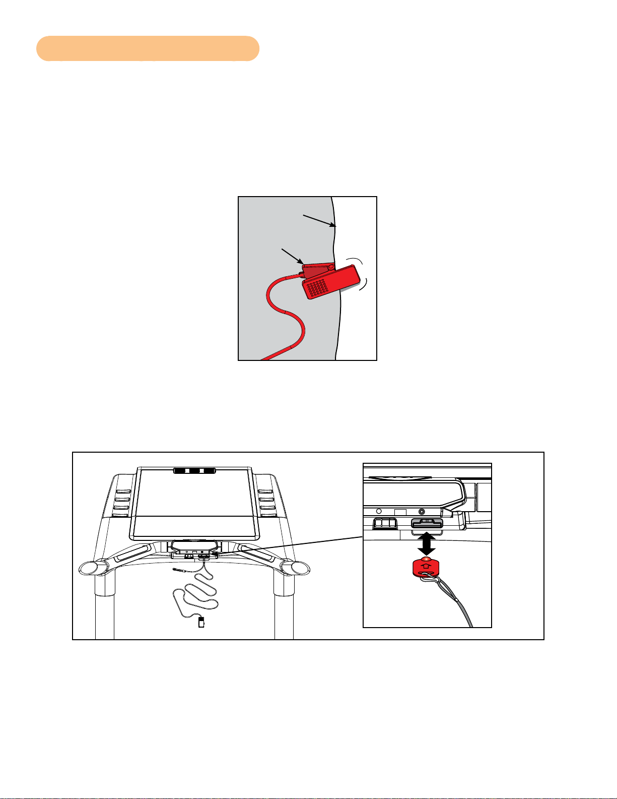
1. Compress the spring and clip the e-stop clamp to your clothing. Ensure the clip engages
enough clothing so it does not fall off in an emergency situation. See Figure 1. Be sure the
string is free of knots and has enough slack for you to workout comfortably with the e-stop key
in place.
Clothing
Clip
Figure 1
2. Without falling off the treadmill, carefully step backward until the e-stop pulls out of the
console. See Figure 2. If the e-stop clip falls off your clothing then the test has failed. Reclip
the e-stop clip to your clothing and repeat this step.
Figure 2
3. Replace the e-stop key. See Figure 2.
4. The treadmill is now ready to be used. Ensure the the e-stop clip is secured to your clothing at
all times during use.
5. After use, remove the e-stop key from the treadmill.
Page 16

Cybex 751T Treadmill Owner’s Manual
The e-stop key can be removed to help prevent unauthorized use. Refer to the Stopping the Treadmill
section in the Operation chapter for more information about the e-stop key.
When not in use store the e-stop clip on the storage tab located on the lower cover. See Figure 3.
Lower Cover
Storage Tab
Figure 3
E-Stop
Clip
CSAFE Ports
The 750T Treadmill has two CSAFE ports, one in the console for CSAFE devices that need access
there, and one under the base of the unit for running a network connection.
The CSAFE standard denes a communication protocol and low-voltage DC power source specic
to the Fitness Equipment Industry. These RJ-45 phone jacks are provided for use ONLY within the
CSAFE protocol. For more information on the CSAFE standard, visit
www.tlinxx.com/csafe. Not every connection carries both the communication and power capability.
The console CSAFE port inside the console contains the full implementation, with both network
communications and a standard CSAFE voltage (minimum 8.0 VDC) power source. The base CSAFE
port is accessible under the base of the treadmill and is for network communications only and does
not contain the DC power source. See Figures 4 and 5.
CSAFE Port
(Lower Socket)
Figure 4
Console CSAFE Port Location
16
Page 17

Base CSAFE Port Location
CSAFE
Port
Bottom View
Figure 5
Page 18

Cybex 751T Treadmill Owner’s Manual
This page intentionally left blank.
18
Page 19

Cybex 751T Treadmill Owner’s Manual
Assembly and Setup
Warnings/Cautions
All warnings and cautions listed in this chapter are as follows:
WARNING: Serious injury or death can occur. To avoid injury or death the following
procedure must be followed. Use extreme caution when assembling the
treadmill. Failure to do so could result in injury.
WARNING: Serious injury or death can occur. To avoid injury or death the following
procedure must be followed. During this procedure STAY OFF THE
RUNNING BELT! Stand with your feet on the two steps.
CAUTION: Serious injury or damage to machine can occur. To avoid injury or damage the
following procedure must be followed. A minimum of two people are required
to lift, move and assemble this treadmill. Always use proper lifting methods
when moving heavy items.
Choosing and Preparing a Site
Before assembling the treadmill a suitable site must selected and have the proper electrical outlet
power available for optimum operation and safety. See the Electrical Power Requirements section
(located on the next page) for direction in locating the treadmill’s voltage requirements.
The area selected for the treadmill should be well lit and well ventilated. Locate the treadmill on
a structurally sound and level surface (do not place in recessed areas or on plush carpet) a few
feet away from walls and other equipment. Each side of the treadmill should have a 19.7” (0.5
m) minimum space. Behind the treadmill should be 79” (2.0 m) minimum of space. Allow enough
clearance for safe access and passage during use of the machine. If the treadmill is to be located
above the rst oor, place it near or above major support beams. If the area has a heavy, plush
carpet, the airow around the base of the machine may be restricted or the carpeting may interfere
with the moving parts. To protect the carpeting and the machinery, place a 3/4” (1.9 cm) thick wood
base under the treadmill.
Do not install the treadmill in an area of high humidity, such as in the vicinity of a steam room,
sauna, indoor pool, or outdoors. Exposure to extensive water vapor, chlorine, and/or bromine could
adversely affect the electronics as well as other parts of the machine.
19
Page 20

Cybex 751T Treadmill Owner’s Manual
Electrical Power Requirements
The power requirements for this treadmill are a grounded, dedicated circuit rated for one of the
following:
• 100 VAC, 50/60 Hz, 20A
• 115 VAC, 60 Hz, 20A
• 220 VAC, 60 Hz, 15A
• 230 VAC, 50 Hz, 15A
• 230 VAC, 50 Hz, 13A, UK
Contact a qualied electrician to ensure the power supply complies with local building codes.
Do not use a ground plug adapter to adapt the 3-prong power cord plug to a non-grounded electrical
outlet. Do not use an extension cord.
Assembling the Treadmill
WARNING: Serious injury or death can occur. To avoid injury or death the following
procedure must be followed. Use extreme caution when assembling the
treadmill. Failure to do so could result in injury.
CAUTION: Serious injury or damage to machine can occur. To avoid injury or damage the
following procedure must be followed. A minimum of two people are required
to assemble this treadmill.
Tools Required
• 1/2” Socket wrench with a 4” extension
• 1/2” Box end wrench, 12 point
• 9/16” Socket wrench with a 4” extension
• Phillips screwdriver
The words “left” and “right” denote the treadmill user’s orientation.
Read and understand all instructions thoroughly before assembling the treadmill.
Each step number in the assembly instructions tells you what you will be doing. The lettered steps
following each step number describe the procedure required. Do not continue with step 2 until you
have carefully read all of the assembly instructions.
Verify you have received the correct package.
Read the sticker on the outside of the box and verify that the model number, color and voltage are
what you ordered. During step 3 and 5 you will verify that the contents of the box match the sticker.
Unpack and verify the contents of the boxes.
1. Lift up and remove the cardboard sleeve that surrounds the treadmill.
20
Page 21

Cybex 751T Treadmill Owner’s Manual
2. Verify the following items are present. Check off () each item as you nd it. See Figure 1. If
any of the parts are missing contact Cybex Customer Service.
Item Qty Part Number Description
1 1 Varies Base assembly
2 1 Varies Console assembly
3 1 AF-19921 Upright, Left
4 1 AF-19922 Upright, Right
5 1 AX-20383 Motor cover, Top
6 1 PL-20264 Motor cover, Front
7 1 PL-20262 Motor cover, Left (i n bo x )
8 1 PL-20263 Motor cover, Right (in b o x)
9 1 PL-20355 Upright cover, Outer, Left (in b o x)
10 1 PL-20211 Upright cover, Inner, Left (in bo x)
11 1 PL-20356 Upright cover, Inner, Right ( i n bo x)
12 1 PL-20357 Upright cover, Outer, Right (in bo x)
13 1 PL-20210 Console cover, Back
14 1 AX-20454 Hardware pack (in box)
15 1 LT-20406-4 Owner’s Manual (in box)
16 1 LT-20404 Assembly poster
17 1 LT-20405 Warranty sheet
18 1 AX-20552 Assembly, E-stop lanyard
#7
#5
#6
#14
#8
#15
#2
#18
#16
#9
#3
#17
#10
#13
#11
#12
#4
Figure 1
#1
21
Page 22

Cybex 751T Treadmill Owner’s Manual
3. Check off () each item in the hardware pack as you nd it. See Figure 2.
Item Qty Part Number Description
19 9 HS-16939 Screw, SEMS, 10-32 x .75”, PNHD, BLK
20 10 HS-16929 Bolt, Whiz Lock, 3/8-16 x .625”, HXHD
21 9 HS-15706 Screw, 8/16 x .50”, PNHD, STL, BLK
22 2 HS-41050 Bolt, 5/16-18 x 2.25”, HXHD
23 2 HS-20361 Screw, SLFTP, 8/16 x 2.5”, Plastite, BLK ZN
24 4 HN-42063 Nut, 5/16-18, Flanged, SS
25 2 HW-00189 Washer, Flat 5/16”
Hardware
#21
#19
#19
#13
#5
#9
#3
#20
#24
#21
#22
#25
#22
#11
#10
#23
#22
#2
#24
#25
#20
#4
#23
#8
#12
#24
#25
Figure 2
#6
#19
#20
#19
#7
#1
22
Page 23

Cybex 751T Treadmill Owner’s Manual
CAUTION: Serious injury or damage to machine can occur. To avoid injury or damage the
following procedure must be followed. A minimum of two people are required
to lift, move and assemble this treadmill. Always use proper lifting methods
when moving heavy items.
Lift and move the treadmill.
At least two people should lift and move the treadmill to a level location where you intend to leave it.
Use proper lifting methods.
Verify the model and voltage.
Verify that you have the correct model and voltage by looking at the serial number label located at the
rear of the unit.
Install the uprights.
1. Locate the left upright (#3) and ve bolts, 3/8-16 x .625” (#20).
2. Carefully place the left upright (#3) on the base assembly (#1) as shown. See Figure 3.
#3
#20
#20
#20
#1
Figure 3
3. Using a 9/16” Socket wrench, partially tighten each of the ve bolts, 3/8-16 x .625” (#20). See
Figure 3.
4. Repeat steps 6A to 6C for the right upright (#4).
23
Page 24

Cybex 751T Treadmill Owner’s Manual
Install the console assembly to the uprights.
1. Locate the console assembly (#2), bolt 5/16-18 x 2.25” HXHD (#22), washer (#25) and two
nuts (#24). See Figure 4.
#2
#22
#24
#25
#3
Figure 4
2. Place the console assembly (#2) in position on the left upright (#3). Do not pinch or damage
display cable when installing console assembly. See Figure 4.
3. Using a 1/2” box end wrench, partially tighten the bolt 5/16-18 x 2.25”, HXHD (#22), washer
(#25) and two nuts (#24). See Figure 4.
4. Repeat steps 7A to 7C for the right upright.
5. Using a 1/2” box end wrench, fully tighten the two bolts, 5/16-18 x 2.25”, HXHD (#22) and four
nuts (#24) securing the console assembly to the uprights. See Figure 4.
6. Using a 9/16” Socket wrench, fully tighten the ten bolts, 3/8-16 x .625” (#20) securing the
uprights to the base assembly (#1). See Figure 3.
24
Page 25

Cybex 751T Treadmill Owner’s Manual
Install the Display Cable.
1. Locate the display cable exiting the back of the console assembly.
2. Insert the display cable into the top of the left upright (#3) until it exits at the base of the upright
(#3). See Figures 5 and 6. Do not pinch or damage display cable when installing.
#3
Display
Cable
#3
Hub Board
Connector
J3
Display
Cable
Figure 5
Figure 6
3. Plug the display cable, located at the bottom of the upright assembly (#3) into the hub board
connector J3. See Figure 6.
If installing the A/V option, refer to the 750T A/V bracket installation instructions (supplied with the A/V
bracket).
Attach the upright covers (four pieces).
1. Locate the outer left upright cover (#9), inner left upright cover (#10) and one screw 8/16 x 2.5”
(#23). See Figure 7.
Figure 7
#23
#9
#10
#3
25
Page 26

Cybex 751T Treadmill Owner’s Manual
2. Place the two upright covers in place over the left upright (#3). See Figure 7.
3. Insert the screw 8/16 x 2.5” (#23) into the inner left upright cover (#10) and secure using a
Phillips screwdriver. See Figure 7.
4. Repeat steps 9A to 9C for the right side.
Attach the back console cover.
1. Locate the back console cover (#13) and nine screws 8/16 x .50” (#21). See Figure 8.
#2
#13
#21 (9)
Figure 8
2. While being sure not to pinch any cables, use a Philips screwdriver to secure the nine screws
8/16 x .50” (#21) that hold the back console cover (#13) to the console assembly (#2). See
Figure 8.
Attach the motor covers (four pieces).
1. Locate the front motor cover (#6) and ve screws 10-32 x .75” (#19). See Figure 9.
#6
#19
#1
Figure 9
2. Elevate or tip the treadmill on it’s side to install the two lower screws (#19).
26
Page 27

Cybex 751T Treadmill Owner’s Manual
3. Using a Phillips screwdriver partially tighten the front motor cover (#6) to the base (#1) with
ve screws 10-32 x .75” (#19). See Figure 9.
4. Locate the left motor cover (#7) and four screws 10-32 x .75” (#19)
5. Using a Phillips screwdriver, partially tighten the left motor cover (#7) with two screws 10-32 x
.75” (#19). See Figure 10.
#19
#8
#7
#19
Figure 10
6. Repeat steps 11C and 11D for the right side.
7. Locate the motor cover top (#5).
8. Place the motor cover top (#5) into position by aligning the four tabs over the front and side
cover screws. See Figure 11.
#5
Tabs
Figure 11
If motor cover top does not t properly, loosen the front and side cover screws as needed.
9. Using a Phillips screwdriver, nish tightening the ve front cover screws and four side cover
screws. Be sure the screws are securing the motor cover’s tabs. See Figure 11.
27
Page 28

Cybex 751T Treadmill Owner’s Manual
Level the treadmill.
Conrm that the treadmill is on a level surface.
Attach emergency stop key.
1. Conrm that the emergency stop key is in place in the bottom of the console handrail. See
Figure 12. The treadmill will not run without the key in place.
Console
Handrail
Emergency
Stop Key
Figure 12
Visually inspect the treadmill.
Carefully examine the treadmill to ensure that the assembly is correct and complete.
WARNING: Serious injury or death can occur. To avoid injury or death the following
procedure must be followed. Be sure that all electrical requirements are
met as indicated in the specications at the front of the manual and at the
beginning of this chapter prior to proceeding.
28
Page 29

Cybex 751T Treadmill Owner’s Manual
Testing the Treadmill Operation
Use the following instructions to test the full speed and incline range of the treadmill and to check the
belt for proper operation.
CAUTION: Serious injury or damage to machine can occur. To avoid injury or damage the
following procedure must be followed. During this procedure STAY OFF THE
RUNNING BELT! Stand with your feet on the two steps.
Cybex recommends that the treadmill be unplugged or the on/off (I/O) power switch turned off (O)
when it is not in use.
1. Without anyone on the treadmill, plug the power cord into a power outlet from a grounded,
dedicated circuit as described under Electrical Requirements in this chapter.
Ensure the power cord is not being pinched under the front of the treadmill.
2. Locate the on/off (I/O) power switch in the front motor cover of the treadmill. Toggle it to the on
position (I).
3. The control panel will light up and be in the Dormant Mode.
4. Press the Quick Start key. The treadmill begins a countdown “BELT START IN 3...2...1” and
sounds a tone for each count. After it reaches one (1), the treadmill gives a longer tone and
then begins accelerating the belt to reach 0.5 mph (0.8 kph).
5. The lower left display will show the incline then time and the lower right display will show the
actual speed.
6. Press and hold down the Speed + key until the treadmill reaches a speed of approximately 4
mph (6.4 kph), as indicated on the display.
7. Observe the belt to see that it is running properly; it should stay centered in the middle of the
deck. If you have problems with the running belt operation, see Running Belt Adjustments in
the Preventive Maintenance chapter.
8. Run the treadmill through its full speed range. First press the Speed + key until the treadmill
reaches its highest speed. Then press the Speed - key until the treadmill is back to 0.5 mph
(0.8 kph).
9. As you press the Incline or Speed + - keys, the respective displays will show the actual
incline or speed.
10. When the treadmill reaches the set incline and speed, the displays will remain steadily
illuminated to indicate that the desired settings have been reached.
11. Run the treadmill through its full % grade range. Press the Incline key until the treadmill
reaches its highest grade (15%). Then press the Incline key until the treadmill reaches -3%
grade.
12. Press the Stop key to stop the running belt, end the workout review and return the display to
Dormant Mode.
29
Page 30

Cybex 751T Treadmill Owner’s Manual
Setup
1. While in Dormant Mode enter Set Up Mode by pressing the following buttons on the keypad
Clear 750 and then press the Enter key. You will now be in the set up menu.
2. Press the Speed + and - keys to scroll through the set up options. Press the Enter key to edit
options, change values with the Incline and keys or the Speed + and - keys. Press
Enter to save your selection and return to the set up menu. Press the STOP key to exit to
Dormant Mode. Press the CLEAR key to reset to the previous stored value, and exit back to
the menu. The set up options are displayed in the following order:
Language (Language):
This selects the language displayed in the text area of the console. Language choices are:
• ENGLISH (Default)
• GERMAN
• FRENCH
• SPANISH
• JAPANESE
• SWEDISH
• RUSSIAN
• DANISH
Units (UNITS):
Choices are “ENGLISH (LB/MPH)” or “METRIC (KG/KPH)” measurements. English is the default.
Frequency (FREQUENCY):
This is the frequency of the power line that supplies power to your treadmill. The default setting is
60 Hz. If you have an English console and a 50 Hz power line frequency , then you must change the
default setting from 60 Hz to 50 Hz for the proper elevation frequency.
Clock Style (HH:MM / MM:DD:YY or DD:MM:YY):
The 750T features a clock and calendar. The clock can be displayed in a 12 or 24 hour format. The
calendar date fomat can be displayed as Month-Day–Year (US) or Day–Month–Year (EU).
“12HR US DATE”
“24HR EURO DATE”
“12HR EURO DATE”
“24HR US DATE”
Current Time (HH:MM):
The 750T features a clock that displays the current time. Examples for 2:57 PM on May 10, 2007.
12HR US DATE “02:57P 5/10/2007”
24HR EURO DATE “14:57 10-05-2007”
12HR EURO DATE “02:57P 10-05-2007”
24HR US DATE “14:57 5/10/2007”
Default Time (DEFAULT TIME):
This is the default time for time based programs if a user does not re-set Time. For example, if you
press Time you can decrease or increase the set workout time up to the amount that the Max time is
set. Choices are 10, 20, 30, 60 and 90 minutes. Default is 30 minutes.
Review Time (REVIEW TIME):
This is the Review Time for which the user’s workout results are displayed at the end of a workout.
Choices are 0:10, 0:20, 0:30, 1:00 and 5:00 minutes. Default is 20 seconds.
30
Page 31

Cybex 751T Treadmill Owner’s Manual
Max Time/Time Zones (MAX TIME = MINUTES, ZONED OR OFF):
This is the maximum amount of time the treadmill can run per user workout session. You can limit the
users time or choose ‘OFF’ to disable the Max Time. Valid choices for Max Time are OFF, 20, 30, 40,
50, 60, 90 and 120 minutes or ZONED. For ZONED, you can dene a user maximum session time
based on four time zones. This allows limiting use only during busy times of the day.
This is how ZONED is congured from the factory:
ZONE1 5:01A 60
ZONE2 9:01A OFF
ZONE3 4:01P 60
ZONE4 9:00P OFF
The maximum session time is limited to 60 minutes from 5AM - 9AM and from 4PM to 9PM in this
example, with all other times unlimited. The zone start/stop time and the time limit in each zone can
be modied to suit your needs.
Pause Time (PAUSE TIME):
This is how long the treadmill retains and displays your current workout data during a pause in the
workout. Choices include: Off; 1 minute; 5 minutes; and 10 minutes; default is Off.
WARNING: Serious injury or death can occur. To avoid injury or death the following
procedure must be followed. It is strongly suggested to not allow any user
on the treadmill without adequate instruction. The use of a treadmill at high
speeds can be dangerous and potentially result in injury. To avoid injury no
user should be allowed to use the treadmill at a speed that exceeds their level
of ability.
The 750T Treadmill has been programmed to have a default maximum speed of 12.4 mph from the
factory. As the owner of this treadmill you may change the default setting for maximum speed up to
15 mph. Please be aware that higher speeds have higher risk and if a user exceeds their ability, they
can potentially loose coordination that can result in injury.
The e-stop clip should be worn at all times.
Max Speed (MAX SPEED):
This is the maximum speed the treadmill will run. Choices are between .5 and 15.6 MPH (0.8 to
25.1 kph). Default MAX SPEED is set at 12.4 MPH (20.0 KPH).
Max Incline (MAX INCLINE):
This is the maximum elevation the treadmill will incline. Choices are between 0 and 15 percent grade.
Setting both the Min and Max incline to 0 percent will disable the elevation.
Min Speed (MIN SPEED):
This is the minimum speed the treadmill will run. Choices are between .5 and 1.0 MPH (0.8 to 1.6
KPH).
Min Incline (MIN INCLINE):
This is the minimum elevation the treadmill will decline. Choices are between -3 and 0 percent grade.
Setting both the Min and Max incline to 0 percent will disable the elevation.
Sound (TONE - ON/OFF):
This option will enable or disable the beeper by toggling it on/off. Default is On.
31
Page 32

Cybex 751T Treadmill Owner’s Manual
Dormant Display Option (DORMANT STYLE):
This denes what is displayed in Dormant mode. Valid Choices for Dormant Display are:
0 – DEFAULT -
1 – TEXT MSG - Not Applicable.
2 – OUT OF ORDER - Out of Order message.
3 – CLOCK - Time clock.
4 – PROFILES - Displays program proles.
Lock Combination (LOCK CODE).
This feature will allow the Lock Combination (PIN) to be changed. It requires the correct PIN number
to be entered rst before allowing any changes.
The PIN numbers will be entered using the keypad. If an incorrect PIN number is entered, the number
will blink once and revert back to underscores. If a valid PIN number is entered, blink the ON or OFF
(default) text (whichever was previously stored) and allow the Speed Control Key to toggle it.
Custom Programs - (SAVE PROGRAM).
The ability to SAVE a workout session as a custom program during Review is enabled or disabled
here. If disabled, the SAVE button will not be active during Review. The text area will display Save
Program On or Save Program OFF (default).
Remember: You must press Enter after changing a value for that value to be stored.
3. To exit Set Up Mode press the Stop key once.
Your treadmill is now ready for use. Follow the instructions in the Operation chapter to learn how to
operate the treadmill. You should begin with walking speeds rst, to be sure everything is functioning
properly.
32
Page 33

Operation
Read and understand all instructions and warnings prior to using the treadmill. See all of the safety
related information located in the safety chapter.
Terms and Symbols Used
This section lists some of the common terms and symbols used in this chapter. Other terms and
symbols are listed in this chapter as appropriate. For setup options see Setup in the Setup and
Assembly Chapter.
Dormant Mode — This occurs when the treadmill is powered up and not in use. Dormant Mode may
display a clock, scrolling text or the Cybex logo if such options are chosen.
Wake-up Mode — This occurs when motion is detected or a key is pressed. A tone will be heard.
Program Setup Mode — This begins after pressing the Programs key, Fit Tests key, Enter key or
the number key corresponding to the program desired.
Active Mode — Active Mode is when the running belt is moving. Before Active Mode begins, a
three second countdown and “BELT START IN 3...2...1” is displayed. Active Mode continues until the
preset time limit is reached, disengage the e-stop key, press the STOP key or press the Pause/End
key.
Quick Start — This begins by pressing the Quick Start key. Quick Start skips the Program Setup
Mode and begins immediately in Quick Start Manual Mode with time counting up.
Manual Mode — In this active mode the user controls all aspects of the workout; the running speed,
the incline and the workout duration. The time will count down, allowing the user to quickly get
moving before entering their weight by pressing the Weight key.
Workout Review — This begins after pressing the Stop key once or at the end of a program
or when the treadmill detects that the user is not there (see Safety Sentry™ in this chapter). The
workout statistics accumulated during the previous workout session will display for the preset review
time.
Pause Mode — Press the Pause/End key once. If Pause is enabled in Setup, the Pause feature will
allow the treadmill to hold the accumulated workout data for up to ve minutes. The time remaining
will be displayed on the screen. Press START at any time to re-start the treadmill. If Pause is not
enabled, this key acts like the STOP key and will end the workout session.
Cool Down — This begins immediately after pressing the Cool Down key. The countdown timer
is set to two minutes, elevation returns to 0% and speed is reduced to 50% of the MET level or 2.5
MPH (4 Km/H) whichever is lower. Repeated presses of the Cool Down key will restart the clock at
two minutes indenitely.
33
Page 34

Cybex 751T Treadmill Owner’s Manual
The last two minutes of a Programs (P1 – P9) will reduce the incline to 0% and the speed to half of
the MET level for each of the two remaining minutes. Cool down will also be active when Manual or
Quick Start workouts end due to the set or max time.
Λ V
— These keys adjust Incline higher or lower.
+ – — These keys adjust Speed up (+) or down (–).
Quick Operation Guide
Maximum user weight is 400 lbs. (181 kg).
The following is a quick overview of the operation of the treadmill. For more information read Detailed
Operation Guide in this chapter.
1. Place your feet on the two top steps located on each side of the running belt.
WARNING: Serious injury or death can occur. To avoid injury or death the following
procedure must be followed. Do not stand on the running belt when starting
the treadmill. Always place your feet on the two top steps when beginning a
workout.
2. Clip the e-stop clip onto your clothing and test it as described under Emergency Stop in the
Safety chapter.
3. Press the Programs, Manual or Fit Tests keys and follow the on-screen setup instructions or
press QUICK START to start the treadmill in Quick Start Manual mode.
4. If a program is selected, you will be prompted for workout Time, Level and Weight as
appropriate. Adjust these settings with the Speed + – keys and press Enter to proceed.
5. The treadmill begins a countdown, “BELT START IN 3...2...1,” after which it accelerates the
belt to 0.5 mph (0.8 kph) (for Manual Mode) or the speed of the program selected.
6. Hold the handrails while you step onto the running belt and begin walking.
7. Press the Speed + – keys to change the belt speed at any time. The right display will show the
current speed.
8. Press the Incline Λ V keys to change the incline at any time. The left display will show incline.
9. Press the Stop key at any time to stop the running belt. Press again to exit to Dormant Mode
and return the incline to 0%.
34
Page 35

Detailed Operation Guide
Maximum user weight is 400 lbs. (181 kg).
1. Plug the treadmill power cord into a power outlet from a grounded, single phase, dedicated
circuit, rated for one of the following:
100 VAC, 50/60 Hz, 20A
115 VAC, 60 Hz, 20A
220 VAC, 60 Hz, 15A
230 VAC, 50 Hz, 15A
230 VAC, 50 Hz, 13A, UK.
2. Set the on/off switch to the on position.
WARNING: Serious injury or death can occur. To avoid injury or death the following
procedure must be followed. Do not stand on the running belt when starting
the treadmill. Always place your feet on the two top steps when beginning a
workout.
3. Place your feet on the two top steps located on each side of the running belt.
4. Clip the e-stop clip onto your clothing and carefully test the e-stop key to ensure it will activate
in case of an emergency. See Emergency Stop Key (e-stop) in Chapter 1 for properly testing
the e-stop key. Also, see Stopping the Treadmill in this chapter for further information about the
e-stop key. Be sure the string is free of knots and has enough slack for you to run comfortably
with the e-stop key in place.
5. You now have the option to select a program, a tness test or enter Manual Mode.
35
Page 36

Cybex 751T Treadmill Owner’s Manual
REVISIONS
DESCRIPTION
See sheet 1
ECO
REV
DATE APPROVAL
BY
.
.
.
START
QUICK
CLEAR
EXIT
INCLINE
END
PAUSE
SHIFT
COOL
DOWN
SCAN
START
QUICK
ENTER
987
0
1
4
32
65
SPEED
WEIGHT
LEVEL
TIME
FAN LO
FAN OFF
FAN HI
SAVE
SPEED
TV
REVISIONS
DESCRIPTION
ECOREV
DATE APPROVALBY
See sheet 1.
.
.
.
. ..
.
.
. ..
.
.
. ..
.
To select a program, press the Programs or Fit Tests key and follow the prompts. Press the Programs
or Fit Tests key multiple times to cycle through its nine programs, or use the numeric keypad to select
the program number. Press Enter to select. See Figure 1.
Heart Rate
Bar Graph
Indicator
T ext Area
Data
Readouts
QUICK
START
Programs
Key Pad
Time / Incline
Speed / PrX
Figure 1
Upon entering a program the display will guide you through the appropriate settings. This is referred
to as Program Setup Mode. If the Quick Start key is pressed now, all defaults for that program will be
accepted. After 10 seconds, if no key has been pressed, the rst default will be accepted. After another
10 seconds the second default will be accepted and so on until the last default. The program will not
enter Active Mode until you press the Enter or Quick Start key. If no key has been pressed for 60
seconds after displaying the last default, then the treadmill will return to the Dormant Mode.
If you choose to enter Manual Mode instead of choosing a program, press the Quick Start or the
Manual key. No prompts will occur when you press Quick Start. While in Manual Mode, customize
your workout Speed, Incline and enter your Weight by pressing those keys.
For the most accurate calorie count, you must set your correct weight before beginning your workout
(including clothing).
When selecting a program you must press Enter after each adjustment of Time, Level and Weight.
6. The treadmill begins a countdown, “BELT START IN 3...2...1,” and sounds a tone for each
count. When it reaches one (1) the treadmill gives a longer tone and then starts accelerating
the belt. In Manual Mode the belt will begin accelerating to 0.5 mph (0.8 kph) and the incline
will remain at zero percent. In a program the belt will begin accelerating and the incline will
change to the corresponding speed and incline of the program and level you selected.
36
Page 37

7. Hold the handrails while you step onto the running belt and begin walking.
8. Observe the control panel. The top center Bar Graph display shows a graphical representation
of the relative incline changes, and if in a program, will show the relative intensity changes
that are coming up. The Text Area will start showing the workout data such as Distance,
Calories, Heart rate (if available), METs and Pace (Minutes per Mile or Minutes per Km). The
data displays will start by automatically shifting every ve seconds. To hold on one display,
press the Shift/Scan key. To continue auto-scan, hold the Shift/Scan key for 3 seconds until it
beeps.
Heart rate will be displayed in lieu of METs if a valid heart rate is available from a wireless chest strap
(not included) or by holding the contact heart rate grips.
When you adjust incline in a program, the change will affect only the current segment. The program
control will resume starting with the next segment. To increase or decrease overall intensity, adjust
the speed and/or the program level.
9. Press the Speed + – keys to change the belt speed at any time. The right display will show the
set speed.
10. Press the Incline Λ V keys to change the incline at any time. The left display will show the
current incline only when incline keys are used, then revert to time.
11. Press the Stop key at any time to stop the workout. Press Stop once to end the workout and
begin the Workout Review. As you press Stop once, the treadmill belt will stop. Press Stop a
second time to clear the Workout Review, return to Dormant Mode and return incline to 0%.
12. If the e-stop key is removed during a workout, the drive motor power shuts off immediately,
causing the belt to stop. “EMERGENGY STOP” is displayed, followed by “REPLACE E-STOP
KEY TO CONTINUE”. Replacement of the e-stop key causes Workout Review to begin.
13. When a program is complete the treadmill begins a countdown, “BELT STOP IN 3...2...1,” and
sounds a tone for each count. The belt slows to a stop and Workout Review is displayed for
the preset time or until you press the Stop key.
14. The treadmill returns to Dormant Mode and the incline returns to 0%.
37
Page 38

Stopping the Treadmill
31 2
WEIGHT
CLEAR ALT
LEVEL
7
4
ENTER
9
0
8
5 6
TIME SAVE
FAN OFF
FAN LO
FAN HI
Cybex 751T Treadmill Owner’s Manual
Press Stop once to end the workout session and start the Workout Review. The treadmill will perform
a controlled belt stop and bring the incline to 0%. The Text Area will be displaying accumulated data
or the results of the Fitness Test for the duration congured in Setup for Review Time (default is 20
seconds.) Press Stop again to exit to Dormant.
The function of the immobilization method: The purpose of immobilizing the treadmill is to
prevent unauthorized use. This can be accomplished by removing the e-stop key from the treadmill,
un-clipping it from the cord and putting it in a non-accessible place. See Figure 2. Immobilization
can also be enabled using the LOCK code. Either temporarily by pressing LOCK during review and
entering the correct PIN number, or permanently by enabling the LOCK feature in SETUP mode. See
the Setup chapter.
The emergency dismount: Follow the steps listed below if you experience pain, feel faint or need to
stop your treadmill in an emergency situation:
Figure 2
1. Grip handrails for support.
2. Step onto the top steps.
3. Pull the e-stop key off the console.
The function of the emergency stop: The e-stop key functions as the emergency stop. In an
emergency situation, remove the e-stop key from the treadmill and the running belt will come to a
stop. See Figure 3.
Figure 3
38
Page 39

Safety Sentry
If you step off of your treadmill during a workout, it is designed to detect your absence and will stop
the belt. Before taking action, the display will beep several times and display “ARE YOU THERE?” on
the text area. If no response in 10 seconds, it will proceed to turn off the belt.
The treadmill will use every sensor available to determine a user is still on the belt before asking if
you are present, then shutting it off. If the user is lighter than 100 lbs. (45 Kg), the motor drive may
not be able to determine they are on the belt. In this instance, the treadmill can only rely on the
motion sensor, key inputs, or the heart rate to establish your presence. It is advisable for lighter users
to stay within the ‘sight’ of the motion sensor (no further back than the end of the handrails) or take
advantage of the wireless heart rate feature to avoid triggering the Safety Sentry.
Control During Operation
Control keys are usable during operation and may be pressed at any time to make adjustments in
speed, elevation or data readouts. The Speed and Incline keys are located near the hand grips,
allowing for thumb adjustments without removing your hands from the hand grips.
Changing Speed — Press the Speed + – keys to change the speed in increments of 0.1 mph or 0.10
kph. Minimum to maximum speed is from 0.5 - 15.6 mph (0.8 - 25.1 kph). Default max speed is 12.4
mph (20.0 kph).
Direct Speed Access — During programs, manual mode and all distance based tness tests a direct
speed value may be entered. Press the “0” key on the numeric keypad and then enter the desired
speed including tenths. Example: For 5 MPH (8.0 KPH) press the “0” key, then press 5-0 (8-0) on the
keypad then press ENTER.
Changing Incline — Press the Incline Λ V keys to change the elevation in increments of 1%.
Elevation ranges from -3 to 15%. Press multiple times to change incline setting. Elevation is dened
as the ratio of rise or fall over run of the treadmill deck.
Workout Time — When the treadmill is in Active Mode, the workout time can be set to a new time
using the TIME key. This will convert a Quick Start session to a Manual Session by dening the
count-down time, or change the total session time in a program. All treadmill usage is limited to the
MAX TIME as congured in Setup.
Changing Data Readouts — Default setting is for Scan to start automatically. Press Shift/Scan to
stop and display a set of data. Press and hold Shift/Scan for three seconds and it will continually
review each set of data. The display shows each set of data for 5 seconds before switching to the
next set.
39
Page 40

Cybex 751T Treadmill Owner’s Manual
Data Readouts
As you exercise, the treadmill keeps track of the following data:
Distance — The total accumulated distance, in miles or kilometers, during your workout. Depending
on the defaults you’ve chosen this measurement will show in English or Metric.
Calories — The total accumulated calories burned during your workout. Your weight must be
correctly set before beginning your workout for this measurement to be most accurate.
Calories Per Hour — Calculation of present workload’s energy exertion in Calories per Hour.
BPM (Beats Per Minute) — Your current heart rate. Heart rate will appear when a signal is
introduced. Use the hand grips for Contact Heart rate or wear a Polar® compatible heart rate chest
strap.
Time — The total time you’ve been working out or time remaining. Display time as hours:minutes.
Pace — At your current speed, how long it would take to cover a mile (or kilometer), displayed in
minutes:seconds.
Metabolic Equivalent (METs) — Relates to the user’s energy expenditure. A MET is a basic unit of
measurement that is used to compare relative work between individuals and activities. ‘One MET’ is
the amount of oxygen consumed at rest. For example, two METs would be twice that amount. If an
individual were working at four METs he/she would be consuming oxygen at a rate equal to four times
their resting consumption. METs can be used to compare walking on a grade with running or even to
cycling and other activities.
To review accumulated data after a program: The display automatically shows the accumulated
workout data during the Workout Review for the set review time. See the Setup chapter.
Displaying Heart Rate
In order for the Cybex 750T to display your heart rate, hold the hand grips to use Contact Heart rate
or wear a Polar® compatible heart rate chest strap.
Contact Heart Rate — Hold the hand grips on the console handrail until a heart rate is displayed,
typically less than thirty seconds. For best results, hold the hand grips lightly and ensure that your
hands contact both the front and back sensors of each grip. Hold your hands as steady as possible
as movement can cause interference on the contacts.
Factors that can interfere with the heart rate signal include:
• excessive movement
• body composition
• hydration
• too loose grip
• too tight grip
• running
• excessive dirt, powder or oil
• leaning or resting on grips
40
Page 41

Cybex does not recommend continuous holding onto the contact heart rate grips during exercise.
.
.
.
Quick Start
1. Press 'Quick Start'.
2. Adjust for speed & incline.
Program Start
1. Press ‘programs’ key to select programs P1 to P8.
Press multiple times or select with arrows.
2. Follow the prompts.
3. Press 'Enter' to begin.
Securely clip e-stop clip onto your clothing.
Contaminants, such as hand lotions, oils or body powder, may come off on the contact heart rate
grips. These can reduce sensitivity and interfere with the heart rate signal. It is recommended that the
user have clean hands when using the contact heart rate.
Heart Rate Zone
Heart rate is described by the number of times your heart beats in a minute. At rest, the average
adult will have a heart rate of about 72 beats per minute (BPM). As one begins to exercise, heart rate
increases and continues to increase as exercise intensity or difculty increases.
Monitoring your heart rate is an effective way to control the intensity of your workout and
subsequently the results it will have. Whether you are a new participant or one with a great deal of
experience, weight loss and other performance goals can be achieved by controlling the intensity of
your workout.
The American College of Sports Medicine recommends that healthy adults exercise between 55 and
85% of their heart rate max. Your heart rate max can be estimated by subtracting your age from 220.
Multiply that estimated heart rate max by .55 to estimate the lower end of your heart rate training
zone. Then multiply your estimated heart rate max by .85 to estimate the higher end of your training
zone. This heart rate training zone gives you a range of intensities at which to exercise. See Figure 4.
This chart shows heart rate based
on percentage and age.
Heart Rate Zone
Beats
Per
Max
Max
85%
85%
65%
65%
Age
20 30 40 50 60 70
220 - Age = Max Heart Rate
Figure 4
Minute
200
180
160
140
120
100
80
60
41
Page 42

Cybex 751T Treadmill Owner’s Manual
Meaning of % Grade
A 1% grade is not the same as a 1 degree incline. The % grade is the relationship of the
measurement of rise over the measurement of run (also called slope). For example, a 1 foot (meter)
rise in height over a length of 100 feet (meters) is a 1% grade. Expressed as a mathematical formula,
the grade is calculated as follows:
1 ft. (m) / 100 ft. (m) = 0.01 = 1%
With respect to treadmills, the percent grade is roughly equal to the increase in height (rise) of the
treadmill divided by the length (run) of the treadmill.
The degree of incline can be related to % grade by taking the Arctangent of the grade. For instance,
15% grade is equal to 8.53 Degrees (ArcTan(.15)=8.53º). The opposite is true to determine % Grade
from Degree of incline (Tan (8.53º)=.15).
Preprogrammed Workouts
WARNING: Serious injury or death can occur. To avoid injury or death the following
procedure must be followed. Obtain a medical exam before beginning any
exercise program. Begin comfortably with a lower level and progress with
higher levels as you become acclimated.
With the 750T, you may choose from Quick Start Manual Mode, nine program choices, eight tness
tests, and nine custom programs. Each routine will be described in detail in this chapter.
Manual Choices:
Quick Start - Press Quick Start. You control speed, elevation.
Manual Mode - Enter time and weight. You control speed, elevation.
Program Choices:
No. Name Levels Data Entries/Selections
P-1 Weight Loss 10 levels. Select time, level and weight.
P-2 Rolling Hills 10 levels Select time, level and weight.
P-3 Hills 10 levels. Select time, level and weight.
P-4 Pikes Peak 10 levels. Select time, level and weight.
P-5 Hill Interval 1:1 10 levels. Select time, level and weight.
P-6 Hill Interval 1:2 10 levels. Select time, level and weight.
P-7 Hill Interval 1:3 10 levels. Select time, level and weight.
P-8 Cardio 10 levels. Select time, level and weight.
P-9 HR Control N/A Select time, age, target heart rate and weight.
42
Page 43

Fitness Test Choices:
REVISIONS
DESCRIPTION
DATE APPROVAL
BY
.
.
CLEAR
EXIT
ENTER
987
0
1
4
32
65
SPEED
WEIGHT
LEVEL
TIME
FAN LO
FAN OFF
FAN HI
SAVE
TV
No. Name Type Data Entry Results
FT1 Gerkin Protocol Walk/run Age, weight and gender. VO2
max.
FT2 Army PFT 2 mile/3.2 k run Age, weight, gender and starting speed. Points.
FT3 Air Force PFT 1.5 mile/2.4 k run Age, weight, gender and starting speed. Points.
FT4 Navy PRT 1.5 mile/2.4 k run
Age, weight, gender and starting speed. Points.
under 5000 feet
FT5 Navy PRT 1.5 mile/2.4 k run
Age, weight, gender and starting speed. Points.
over 5000 feet
FT6 Marines PRT 3 mile/4.8 k run sea
Age, weight, gender and starting speed. Points.
level
FT7 Marines PRT 3 mile/4.8 k run
Age, weight, gender and starting speed. Points.
4500 feet
FT8 One Mile 1 mile/1.6 k walk Age, weight, gender and starting speed. VO2
max.
PFT means Physical Fitness Test and PRT means Physical Readiness Test.
Custom Programs
Custom Programs can be created on-the-y by saving your routine after completion. To do this, press
Save while in Review Mode. The display will prompt you to select a program number of P01 – P09
and to overwrite any if they already exist.
Custom Programs can be run simply by pressing the Programs key and keying in P01 – P09. Note
that these programs do not have a level or time, as these are aspects that were saved as part of the
program itself.
Alarm
During a workout session, you can set an alarm time. When this time is reached, the display will show
‘ALARM’ and the console will continuously beep. Pressing Alarm, Enter or Clear will disable the
alarm. To set the alarm, press the keypad #8 (labeled with the alarm clock). Use the Speed Control
Keys or the keypad to congure the alarm time, pressing ENTER after the Hour and Minutes. See
Figure 5.
Figure 5
Alarm
43
Page 44

Cybex 751T Treadmill Owner’s Manual
REVISIONS
DESCRIPTION
DATE APPROVAL
BY
.
.
CLEAR
EXIT
ENTER
987
0
1
4
32
65
SPEED
WEIGHT
LEVEL
TIME
FAN LO
FAN OFF
FAN HI
SAVE
TV
ECOREV
.
.
.
.
.
.
.
.
Please see Page 1 for revision history
REVISIONS
DESCRIPTION
ECOREV
DATE APPROVALBY
.
.
.
. ..
.
.
. . .
.
.
. . .
.
Please see Page 1 for revision history
REVISIONS
DESCRIPTION
ECOREV
DATE APPROVALBY
.
.
.
. ..
.
.
. . .
.
.
. . .
.
Please see Page 1 for revision history
REVISIONS
DESCRIPTION
ECOREV
DATE APPROVALBY
.
.
.
. ..
.
.
. . .
.
.
. . .
.
Please see Page 1 for revision history
REVISIONS
DESCRIPTION
ECOREV
DATE APPROVALBY
.
.
.
. ..
.
.
. . .
.
.
. . .
.
Please see Page 1 for revision history
Fan
A built in fan is located at the top center of the console to help keep you cool during your workout.
Default speed is OFF during active mode. Press the FAN HI or FAN LO key to control fan speed.
Press the FAN OFF key to turn fan off. See Figure 6.
Fan Controls
Figure 6
Audio Visual (AV) Key Pad – Optional
Figure 7
Console Key Description
EPG
CHANNEL
If an Electronic Program Guide (EPG) is available, this will be
displayed on the TV. Use the CHANNEL Λ V and VOLUME < >
keys to navigate in the EPG, ENTER to accept any selections, and
CLEAR/EXIT to exit the EPG mode.
Toggle down or up to change channel (beeping will occur).
VOLUME
VIDEO SOURCE
Press appropriate keys to increase or decrease volume. There is no
display interaction.
Press to toggle between video source A for cable channels and video
source B for external inputs, such as iPod® video.
44
Page 45

VIDEO PORT
REVISIONS
DESCRIPTION
ECOREV
.
.
.
.
.
.
.
.
Please see Page 1 for revision history
REVISIONS
DESCRIPTION
ECOREV
.
.
.
.
.
.
.
.
Please see Page 1 for revision history
REVISIONS
DESCRIPTION
ECOREV
DATE APPROVALBY
.
.
.
. ..
.
.
. . .
.
.
. . .
.
Please see Page 1 for revision history
Video capable port allows personal entertainment device or other
composite video input.
1 – Video 3 – Left
2 – Ground 4 – Right
USB PORT
Universal Serial Bus (USB) allows different devices to be connected
using a single standardized interface port for charging only.
HEAD PHONE PORT
Head phone port allows personal headphones.
Statistics
The Statistics screen allows you to track the usage and information about the treadmill. The Statistics
screen can be opened when the treadmill is not in use. Using the keyboard, press the key sequence
Clear 999 and Enter.
The ENTER key is active to advance to the next screen. The Speed control keys are active to also
move forward or backward in the menu.
The Stastics menu is as follows:
ST1 - ODOMETER
ST2 - HOURS
ST3 - STARTS
ST4 - MOVES
ST5 - ERRORS
ST6 - SERVICE
ST7 - PGM USAGE
ST1 - ODOMETER
Displayed as “KM XXXX.X” or “MI XXXX.X” where X is the total miles accumulated and units are
either Miles or Km, depending on the setup. Values range from 0.0 – 999,999.9 Miles/Km.
ST2 - HOURS
Displayed as “HOURS XXXXXX” where X is the total time the belt has run in hours. Values range
from 0 – 99999
ST3 - STARTS
Displayed as “STARTS XXXXXX” where X is the number of times the belt drive started the running
belt, regardless of mode. Expect numbers from 0 – 999999
ST4 – MOVES
Displayed as “MOVES XXXXXXX” where X is the number of incline moves in 1% increments. Values
range from 0 – 9,999,999
45
Page 46

Cybex 751T Treadmill Owner’s Manual
ST5 - ERRORS
Error codes are stored in a log to inform the owner or technician of potential problems with the
treadmill. Some errors are used to track unusual conditions, like the treadmill being turned off or a
power outage while in motion. Most errors indicate a potential problem with the treadmill and can be a
valuable tool in diagnosing the cause. Any condition that may cause a hazard will disable the treadmill
and show ‘OUT OF ORDER’ on the console.
WARNING: Serious injury or death can occur. To avoid injury or death the following
procedure must be followed. All maintenance activities shall be performed by
qualied personnel. Failure to do so could result in serious injury.
Cybex is not responsible for performing regular inspection and maintenance actions for your treadmill.
Instruct all personnel in equipment inspection and maintenance actions and also in accident reporting/
recording. Contact Cybex Customer Service at 888-462-9239 or 508-533-4300 for any preventive
maintenance or service concerns.
Error codes are stored in a log of 20 entries, each stamped with time and date with the most recent
being the rst in the log, the oldest the last in the log. Error codes are displayed in the following
format: [Log Entry #] [Actual Error Code #] [Time] [Date], “ERR 1 141 03:49 1/14/2007”.
Press the Incline Control Keys to increment / decrement the Log count to view the next or previous
error. While displaying the error log press and hold the CLEAR button for three seconds to clear all
errors. The display will show “NO ERRORS” when cleared.
ERROR 1 - No Speed at Startup. The display commanded a belt start but the drive did not respond
with a belt speed within timed limits.
ERROR 3 - Speed Irregularity. The drive is reporting a slower speed than the display is
commanding, or a speed of zero after a correct speed had been established.
ERROR 5 - Drive Communications Lost. The display lost communications with the drive, where the
drive has not given a valid response in 350 ms.
ERROR 6 - Speed Irregularity/Overspeed. If the display has received good belt speed information
at the startup, yet the drive begins sending values outside the expected it is reported as belt speed
lost.
ERROR 7 - Controller Over-Current (Fold-back). If the display receives motor current information
from the drive that is outside of desired parameters.
ERROR 8 - Approaching Over-Temperature. Internal controller temperature too high.
ERROR 9 - Display watchdog triggered. If the Display Watchdog is triggered the console will
reboot.
ERROR 92 - Over Current (Output). Controller output current too high.
ERROR 93 - Over Voltage (DC Link). Internal controller voltage too high.
ERROR 94 - Over Heat (Heatsink). Controller temperature too high.
ERROR 95 - Low Voltage (DC Link). Drive measures a low voltage on the input line.
ERROR 96 - Thermal Integrator of output current. Drive measures a high current peak on the
output line.
46
Page 47

ERROR 98 - Display Communications lost. Without drive belt movement. The drive lost
communications with the display, where the display has not sent a valid response in 400 ms.
ERROR 99 - Display Communications lost. With drive belt movement. The drive lost
communications with the display, where the display has not sent a valid response in 400 ms.
ERROR 103 - Input Current OC trip (110 VAC only). Drive measures a high current peak on the
input line.
ERROR 105 - Thermal Integrator of Input Current (110 VAC only). Input current is out of expected
range.
ERROR 140 - Can not nd home position on power-up. The display does not receive a signal from
the zero position switch during power up.
ERROR 141 - Can not nd home position in normal use. The display does not receive a signal
from the zero position switch during use.
ERROR 142 - Out of incline range (over 15% or lower than -3%). The display receives a position
switch report that is outside of expected limits.
ERROR 150 - Out of Speed Range (over 150hz). The display receives a report of belt speed that is
over the expected speed.
ST6 – SERVICE
Displays the count-down to the next required service in miles or kilometers remaining. Also allows for
resetting this odometer when a service has been performed.
Displayed as “SERVICE IN XXXXX MI (or KM)” where XXXXX is the distance until the next scheduled
maintenance. The odometer is set to 15,000 miles (24,140 Km). The Odometer counts down from
15,000 (24,140 Km) miles to 0 before displaying the Service message. Press and hold the CLEAR
key for three seconds while displaying the service odometer will reset it to 15,000 miles (24,140 Km).
ST7 – PGM USAGE
Each program has an individual usage meter associated with it to allow you to track frequency of use.
Displayed as “PR Y XXXXXX” where Y is the program number and XXXXX is the number of times
this program was started (program chosen, setup completed and the treadmill enters Active Mode.)
Use the Speed Control Keys to scroll through the 9 xed and 9 custom program slots and view the
number of starts for each.
47
Page 48

Cybex 751T Treadmill Owner’s Manual
This page intentionally left blank
48
Page 49

Preventive Maintenance
Warnings/Cautions
All warnings and cautions listed in this chapter are as follows:
WARNING: Serious injury or death can occur. To avoid injury or death the following
procedure must be followed. All maintenance activities shall be performed by
qualied personnel. Failure to do so could result in serious injury.
WARNING: Serious injury or death can occur. To avoid injury or death the following
procedure must be followed. To prevent electrical shock, be sure that power
is shut off and the treadmill is unplugged from the electrical outlet before
performing any cleaning or maintenance procedures.
WARNING: Serious injury or death can occur. To avoid injury or death the following
procedure must be followed. Keep wet items away from inside parts of the
treadmill. Electrical shock could occur even if the treadmill is unplugged.
Do not touch components on the lower board. A charge can remain after
unplugging the power cord and turning off the treadmill.
Regular Maintenance Activities
WARNING: Serious injury or death can occur. To avoid injury or death the following
procedure must be followed. All maintenance activities shall be performed by
qualied personnel. Failure to do so could result in serious injury.
Preventive maintenance activities must be performed to maintain normal operation of your treadmill.
Keeping a log sheet of all maintenance actions will assist you in staying current with all preventive
maintenance activities. See Service Schedule located at the end of this chapter.
Worn or damaged components shall be replaced immediately or the treadmill removed from service
until the repair is made.
Cybex is not responsible for performing regular inspection and maintenance actions for your
treadmill. Instruct all personnel in equipment inspection and maintenance actions and also in accident
reporting/recording. Contact Cybex Customer Service at 888-462-9239 or 508-533-4300 for any
preventive maintenance or service concerns.
Page 50

Cybex 751T Treadmill Owner’s Manual
Cleaning Your Treadmill
When cleaning your treadmill spray a mild cleaning agent, such as a water and dishsoap solution,
on a clean cloth rst and then wipe the treadmill with the damp cloth. Do not spray cleaning solution
directly on the treadmill. Direct spraying could cause damage to the electronics and may void the
warranty.
WARNING: Serious injury or death can occur. To avoid injury or death the following
procedure must be followed. To prevent electrical shock, be sure that power
is shut off and the treadmill is unplugged from the electrical outlet before
performing any cleaning or maintenance procedures.
After Each Use — Wipe up any liquid spills immediately. After each workout, use a cloth to wipe up
any remaining perspiration from the handrails and painted surfaces.
Be careful not to spill or get excessive moisture between the edge of the display panel and the
console, as this might create an electrical hazard or cause failure of the electronics.
As Needed — Vacuum any dust or dirt that might accumulate under or around the treadmill. Motors
are especially susceptible to dust and dirt, and restricted airow can prevent adequate cooling that
could shorten motor life. Cleaning this area should be done as often as indicated in the Service
Schedule.
WARNING: Serious injury or death can occur. To avoid injury or death the following
procedure must be followed. Keep wet items away from inside parts of the
treadmill. Electrical shock could occur even if the treadmill is unplugged.
Do not touch components on the lower board. A charge can remain after
unplugging the power cord.
To clean the motor components, you must loosen the four Phillips head screws that hold the motor
cover in place. Lift the cover straight up; the screws and side covers will stay in place. Use a vacuum
attachment or hand vacuum to clean the exposed elevation assembly, drive motor, lower electronics
and the surrounding areas.
Also use a dry cloth for the areas that you can not reach with the vacuum cleaner. If the machine has
not been used for some time or is excessively dirty, use a dry cloth to wipe all exposed areas.
Carefully raise the rear of the treadmill and roll it back from its present position to vacuum the oor
area underneath the unit. When nished, return the treadmill to its normal position.
Contact Heart Rate Grips — Contaminants, such as hand lotions, oils or body powder, may come off
on the contact heart rate grips. These can reduce sensitivity and interfere with the heart rate signal.
It is recommended that the user have clean hands when using the contact heart rate. Clean the grips
using a cloth dampened with a cleaning solution containing rubbing alcohol. The grips are the only part
of the treadmill you should use a cleaning solution containing rubbing alcohol.
50
Page 51

Running Belt Maintenance
Belt and Deck — Wipe the belt surface and the deck area with a clean dry towel to minimize
the effect of friction between the deck and the running belt. This should be done often to prevent
premature wear of the deck, running belt, and the drive motor system. See the Service Schedule at
the end of this chapter.
The running belt may become loose and slip on the drive roller with each foot plant. If it does, follow
the Tensioning and Centering the Belt procedure below. See the Service Schedule in this chapter for
a minimum schedule for checking the belt tension.
Tension and Center the Belt — If the belt is slipping under each step perform this procedure:
Tools Required
3/4” Socket wrench
Tension the belt.
1. Use a 3/4” socket wrench to turn each bolt 1/2 turn clockwise. See Figure 1. Be sure to adjust
each bolt equally on each side.
2. Press the Quick Start key.
3. Press the Speed + to bring the speed up to 3.5-4 mph (5.6-6.4 kph). Allow the treadmill to run
for a minute.
4. Observe the belt to be sure it stays centered. If it is not centered follow step 2.
5. Walk on the belt to see if it still slips. If it does restart this procedure at step 1 A. If you have
to do this procedure three times and it still slips call Cybex Customer Service. Follow the next
step to be sure the belt is centered.
Be careful not to over tighten the belt. Over tightening the belt can cause the belt to stretch and
require replacement.
Figure 1
Page 52

Cybex 751T Treadmill Owner’s Manual
Center the belt.
While centering the belt choose one bolt to adjust. Do not adjust both bolts.
1. With the treadmill running at 5 mph (8 kph) observe the running belt. If the belt tracks off
center to the right or left, the deck will become exposed. Use a 3/4” socket wrench to tighten
the rear roller bolt on the side of the treadmill toward which the belt is moving. For example: If
the belt moves to the right and the deck becomes exposed on the left, tighten the bolt on the
right side of the frame, tighten about 1/2 of a turn (clockwise) and wait 30 seconds. If the belt
does not move back to the center of the treadmill, make another adjustment to the same bolt.
Once the running belt has been adjusted closer to the center of the treadmill, use about 1/4 of
a turn until the belt has been stabilized.
2. After the belt has been centered, check the belt tension again. Make sure the running belt
tension is tight enough so that the belt does not slip or hesitate when stepped on. Walk on the
treadmill at 3.5-4 mph (5.6-6.4 kph) and every 4th to 5th step throw your weight into your step
to feel if the belt is slipping. If the belt does slip, use a wrench to equally tighten both rear roller
adjustment bolts 1/2 of a turn (clockwise). Adjust the belt until no further slipping is felt.
Checking the Belt and Deck Surfaces — The running belt and deck should be checked periodically
for any excessive wear. In an effort to make sure that the running belt operates properly, visually
inspect the belt often to make sure that there are no tears or fraying in the belt material. The running
belt should be replaced and the running deck ipped every 15,000 miles (24,140 km). A service
prompt will appear at this interval and the parts will need to be replaced.
Inspect the edges of the belt as described below.
Tools Required
None
Disconnect the external power source.
1. Turn the main power switch on the front of the unit to the off (O) position.
2. Unplug the treadmill from the power outlet.
Check the belt and deck condition.
1. Look at the edges of the belt while you roll it by hand. If the belt has any rips or looks
excessively worn the belt needs to be replaced.
2. Run your hand under the belt on the top of the deck surface. If you feel excessive ridges or
cracks, or if any wood is exposed under the black surface, the deck should be replaced. In
time, a worn belt and deck can cause high current draw and ultimately, motor failure.
If the running belt and deck need replacement refer to a qualied service technician.
52
Page 53

Other Preventive Maintenance
Other preventive maintenance activities must be completed by a qualied service technician at the
recommended intervals listed in the Service Schedule at the end of this chapter. These activities
include:
• Replace the running deck
• Replace the running belt
Elevation Motor Lubrication — In time the elevation motor pivot points may develop a squeak.
Lubricate the upper and lower bolts and the spacers with a small amount of lithium grease. You can
buy lithium grease at an auto parts store.
Static Electricity — Depending upon where you live, you may experience dry air, causing a
common experience of static electricity. This may be especially true in the winter time. You may
notice a static build-up just by walking across a carpet and then touching a metal object. The same
can hold true while working out on your treadmill. You may experience a shock due to the buildup of static electricity on your body and the discharge path of the treadmill. If you experience this
type of situation, you may want to increase the humidity to a comfortable level through the use of a
humidier.
Service Schedule
All maintenance activities shall be performed by qualied personnel. Failure to do so could result in
serious injury.
This is the minimum recommended service.
Determine mileage.
1. While in Dormant Mode enter Statistics Mode by pressing the sequence CLEAR 999 and
ENTER. The ENTER key is active to advance to the next screen. The SPEED control keys are
also active to move forward or backwards in the menu.
2. Press the SPEED control keys to display “6-SERVICE” and miles or kilometers to the next
required service will be displayed.
3. Record Mileage. Displays the count-down mileage to the next required service. Mileage start
at 15,000 miles (24,140 Km) and counts down to 0.
To exit Statistics Mode, press the CLEAR key .
First 500 miles (800 km).
Check running belt tension and tracking.
Every 5,000 miles (8,000 km).
Check running belt tension and tracking.
•
• Move treadmill and vacuum underneath.
• Raise elevation to 15%, carefully tip treadmill up on the console to clean underneath with a dry
cloth and vacuum. Return to normal position when done.
Page 54

Cybex 751T Treadmill Owner’s Manual
Every 15,000 miles (24,140 km).
• Replace running belt and ip deck.
• Check elevation assembly and replace worn parts.
• Lubricate elevation pivot points.
Every 30,000 miles (48,280 km).
Replace running belt and deck.
Resetting the service odometer.
1. While in Dormant Mode enter Statistics Mode by pressing the sequence CLEAR 999 and
ENTER. The ENTER key is active to advance to the next screen. The SPEED control keys are
also active to move forward or backwards in the menu.
2. Press the SPEED control keys to display “6-SERVICE” and miles or kilometers to the next
required service will be displayed.
3. Press and hold the CLEAR key for three seconds to reset the service odometer to 15,000
miles (24,140 km).
Service may be performed before the 15,000 miles (24,140 km) service prompt appears. Perform the
service on the unit and follow the above procedure to reset the service odometer to zero.
Displays the count-down to the next required service in miles remaining. Also allows for resetting this
odometer of a service has been performed.
Displayed as “SERVICE IN XXXXX MI (or KM)” where XXXXX is the distance until the next scheduled
maintenance. The odometer is set to 15,000 miles (24,140 Km). The Odometer counts down from
15,000 (24,140 Km) miles to 0 before displaying the Service message. Press and hold the CLEAR
key for three seconds while displaying the service odometer will reset it to 15,000 miles (24,140 Km).
54
Page 55

Cybex 751T Treadmill Owner’s Manual
Customer Service
Contacting Service
Hours of phone service are Monday through Friday from 8:30 a.m. to 6:00 p.m. Eastern Standard
Time.
For Cybex customers living in the USA, contact Cybex Customer Service at 888-462-9239.
For Cybex customers living outside the USA, contact Cybex Customer Service at
508-533-4300 or fax 508-533-5183.
Serial Numbers and Voltage
The base serial number can be found on the rear of your treadmill. For your convenience, record your
serial numbers and voltage below so that you will have it ready if you call Cybex Customer Service.
Serial Number Voltage
Serial
Number
55
Page 56

Cybex 751T Treadmill Owner’s Manual
Return Material Authorization (RMA)
The Return Material Authorization (RMA) system outlines the procedures to follow when returning
material for replacement, repair, or credit. The system assures that returned materials are properly
handled and analyzed. Perform the following procedures carefully.
Contact your authorized Cybex dealer on all warranty-related matters. Your local Cybex dealer will
request an RMA from Cybex, if applicable. Under no circumstances will defective parts or equipment
be accepted by Cybex without proper RMA and an Automated Return Service (ARS) label.
1. Call Customer Service for the return of any item that is defective.
2. Provide the technician with a detailed description of the problem you are having or the defect
in the item you wish to return.
3. Provide the model and serial numbers of your treadmill. See Serial Numbers and Voltage.
4. At Cybex’s discretion, the technician may request that you return the problem part(s) to Cybex
for evaluation and repair or replacement. The technician will assign you an RMA number and
will send you an ARS label. The ARS label and RMA number must be clearly displayed on
the outside of the package that contains the item(s) to be returned. Include a description of
the problem, the serial number of the treadmill and the name and address of the owner in the
package along with the part(s).
5. Forward the package through UPS to Cybex.
Attn: Repair Department
RMA # _______________
Cybex International, Inc.
10 Trotter Drive
Medway, MA 02053 USA
Merchandise returned without an RMA number on the outside of the package or shipments sent
C.O.D. will not be accepted by the Cybex receiving department.
Damaged Parts
Materials damaged in shipment should not be returned for credit. Shipping damages are the
responsibility of the carrier (UPS, Federal Express, trucking companies, etc.).
Apparent Damage — Upon receipt of your shipment, check all boxes carefully. Any damage seen
with a visual check must be noted on the freight bill and signed by the carrier’s agent. Failure to do
so will result in the carrier’s refusal to honor your damage claim. The carrier will provide you with the
required forms for ling such claims.
Concealed Damage — Damage not seen with a visual check upon receipt of a shipment but noticed
later must be reported to the carrier as soon as possible. Upon discovery of the damage, a written
or phone request to the carrier asking them to perform an inspection of the materials must be made
within ten days of the date of delivery. Keep all shipping containers and packing materials, they will
be needed as part of the inspection process. The carrier will provide you with an inspection report
and the necessary forms for ling a concealed damage claim. Concealed damage is the carrier’s
responsibility.
56 57
Page 57

Cybex 751T Treadmill Owner’s Manual
Ordering Parts
Online www.cybexintl.com
Fax 508-533-5183
Email parts@cybexintl.com
Phone 888-462-9239 (for customers living within the USA)
508-533-4300 (for customers outside the USA)
CAUTION
Use only Cybex replacement
parts when servicing.
Failure to do so could result
in personal injury.
All inspections and repairs must be performed by trained service personnel only.
Cybex will void warranty if non-Cybex replacement parts are used.
57
Page 58

Cybex 751T Treadmill Owner’s Manual
This page intentionally left blank
58 PB
Page 59

Cybex 751T Treadmill Owner’s Manual
Appendix A - Technical Specications
Specifications
Length: 80” (204 cm).
Width: 34” (86 cm).
Running Area: 22” x 62” (56 cm x 157 cm).
Weight of Product: 410 lbs. (186 kg).
Shipping Weight 440 lbs. (200 kg).
Speed Range: 0.5 to 15.6 mph (0.8 to 25.1 kph) in 0.1 mph or 0.1 kph increments.
Default Max Speed is
12.4 mph (20.0 kph).
Incline Range: -3 to 15% grade.
Manual Mode: Yes.
Programs: Quick Start plus Manual, Weight Loss, Rolling Hills, Hills, Pikes Peak, Hill
Interval 1:1, Hill Interval 1:2, Hill Interval 1:3, Cardio, HR Control, eight
Fitness Tests and nine Custom Programs.
Standard Features: Safety Sentry™, Contact Heart Rate, Polar
strap not included), CSAFE, frame color choices include white texture,
black texture, metaltone gold, black chrome and platinum sparkle.
Optional Features: Unlimited custom colors available.
Power Requirement: Grounded, single phase, dedicated line (discreet power and return for each
circuit) and one of the following:
• 100 VAC, 50/60 Hz, 20A. • 115 VAC, 60 Hz, 20A.
• 220 VAC, 60 Hz, 15A. • 230 VAC, 50 Hz, 15A.
• 230 VAC, 50 Hz, 13A.
Motor: 3.0 hp Continuous, 6.0 hp Peak, AC, Brushless.
Emergency Stop: Pull the emergency stop key (e-stop).
Maximum User Weight: 400 lbs. (181 kg).
Options: Embedded A/V channel and volume controls and video mount bracket.
®
wireless heart rate (chest
34”
(86 cm)
80” (204 cm)
59
Page 60

Cybex 751T Treadmill Owner’s Manual
This page intentionally left blank
60
 Loading...