

CYBEX 750T, 751T Owner's Manual

Cybex 750T Treadmill
Product Number 751T
Owner’s Manual
Cardiovascular Systems
Part Number LT-20406-4 H
www.cybexinternational.com


Cybex 750T Treadmill
Product Number 751T
Owner’s Manual
Cardiovascular Systems
Part Number LT-20406-4 H
Cybex® and the Cybex logo are registered trademarks of Cybex International, Inc. Safety Sentry™ is a registered trademark of Cybex
International, Inc. Polar® is a registered trademark of Polar Electro Inc.
DISCLAIMER: Cybex International, Inc. makes no representations or warranties regarding the contents of this manual. We reserve the
right to revise this document at any time or to make changes to the product described within it without notice or obligation to notify any
person of such revisions or changes.
© 2010, Cybex International, Inc. All rights reserved. Printed in United States of America.
10 Trotter Drive Medway, MA 02053 • 888-462-9239 • 508-533-4300 • FAX 508-533-5183
www.cybexinternational.com • techhelp@cybexintl.com • LT-20406-4 H • March 2010


Cybex 750T Treadmill Owner’s Manual
Table of Contents
Front Pages
About this Manual . . . . . . . . . . . . . . . . . . iii
FCC Compliance Information . . . . . . . . . . iii
1 Safety
Important Voltage Information . . . . . . . 1-1
Grounding Instructions . . . . . . . . . . . . . 1-1
Important Safety Instructions . . . . . . . . 1-2
Warning Decals . . . . . . . . . . . . . . . . . . 1-4
Caution Decals . . . . . . . . . . . . . . . . . . . 1-6
Emergency Stop Key (e-stop) . . . . . . . 1-6
CSAFE Ports. . . . . . . . . . . . . . . . . . . . . 1-7
2 Assembly and Setup
Warnings/Cautions . . . . . . . . . . . . . . . . 2-1
Choosing and Preparing a Site . . . . . . 2-1
Electrical Power Requirements . . . . . . 2-2
Assembling the Treadmill . . . . . . . . . . . 2-2
Testing the Treadmill Operation . . . . . 2-10
Seup . . . . . . . . . . . . . . . . . . . . . . . . . . 2-11
3 Operation
Terms and Symbols Used . . . . . . . . . . 3-1
Quick Operation Guide. . . . . . . . . . . . . 3-2
Detailed Operation Guide . . . . . . . . . . . 3-2
Stopping the Treadmill . . . . . . . . . . . . . 3-5
Immobilization Method . . . . . . . . . . 3-5
Emergency Dismount . . . . . . . . . . . 3-5
Emergency Stop . . . . . . . . . . . . . . . 3-5
Safety Sentry™. . . . . . . . . . . . . . . . . . . 3-5
Control During Operation . . . . . . . . . . . 3-6
Data Readouts . . . . . . . . . . . . . . . . . . . 3-6
Displaying Heart Rate. . . . . . . . . . . . . . 3-7
Heart Rate Zone . . . . . . . . . . . . . . . . . . 3-8
Meaning of % Grade . . . . . . . . . . . . . . 3-8
Preprogrammed Workouts . . . . . . . . . . 3-9
Custom Programs . . . . . . . . . . . . . . . . 3-9
Alarm . . . . . . . . . . . . . . . . . . . . . . . . . 3-10
Fan . . . . . . . . . . . . . . . . . . . . . . . . . . . 3-10
Audio Visual (AV) Key Pad – Optional 3-11
Statistics . . . . . . . . . . . . . . . . . . . . . . . 3-12
4 Preventive Maintenance
Warnings/Cautions . . . . . . . . . . . . . . . . 4-1
Regular Maintenance Activities . . . . . . 4-1
Cleaning Your Treadmill . . . . . . . . . . . . 4-1
Running Belt Maintenance . . . . . . . . . . 4-3
Other Preventive Maintenance . . . . . . . 4-5
Service Schedule . . . . . . . . . . . . . . . . . 4-6
5 Customer Service
Contacting Service . . . . . . . . . . . . . . . . 5-1
Serial Number and Voltage . . . . . . . . . 5-1
Return Material Authorization (RMA) . . 5-2
Damaged Parts. . . . . . . . . . . . . . . . . . . 5-2
Ordering Parts . . . . . . . . . . . . . . . . . . . 5-3
Appendix A - Technical Specifications . . A-1
Appendix B - Program Overview . . . . . . . B-1
Appendix C - Parts List . . . . . . . . . . . . . . . C-1
Appendix D - Exploded Views. . . . . . . . . . D-1
Appendix E - Schematics . . . . . . . . . . . . . E-1
Page i

Cybex 750T Treadmill Owner’s Manual
Page ii

Cybex 750T Treadmill Owner’s Manual
About This Manual
An Owner’s Manual is shipped with each unit. To purchase additional copies of this manual or any other
Cybex manual, please do one of the following:
• fax your order to 508-533-5183
• contact Cybex Customer Service at 888-462-9239
• or contact Cybex Customer Service at 508-533-4300
To contact Cybex with comments about this manual you may send email to techhelp@cybexintl.com.
FCC Compliance Information
WARNING: Changes or modifi cations to this unit not expressly approved by the party
responsible for compliance could void the user’s authority to operate the equipment.
This equipment has been tested and found to comply with the limits for a Class A digital device, pursuant
to Part 15 of the FCC Rules. These limits are designed to provide reasonable protection against harmful
interference in a residential installation. This equipment generates, uses and can radiate radio frequency
energy and, if not installed and used in accordance with the instructions, may cause harmful interference
to radio communications. However, there is no guarantee that interference will not occur in a particular
installation. If this equipment does cause harmful interference to radio or television reception (which
can be determined by turning the equipment off and on) the user is encouraged to try to correct the
interference by one or more of the following measures:
Reorient or relocate the receiving antenna.•
Increase the separation between the equipment and receiver.•
Connect the equipment into an outlet on a circuit different from that to which the receiver is •
connected.
Consult the dealer or an experienced radio TV technician for help.•
Page iii

Cybex 750T Treadmill Owner’s Manual
Page iv
Cybex 750T Treadmill Owner’s Manual
1 - Safety
IMPORTANT: Read all instructions and warnings before using the treadmill.
Important Voltage Information
Before plugging the power cord into an electrical outlet, verify that the voltage requirements for the site
match the voltage of the treadmill that has been received. The power requirements for the Cybex 750T
Treadmill include a grounded, dedicated circuit, rated for one of the following:
100 VAC, 50/60 Hz, 20A•
115 VAC, 60 Hz, 20A•
220 VAC, 60 Hz, 15A•
230 VAC, 50 Hz, 15A•
230 VAC, 50 Hz, 13A, UK•
See the serial number decal for the exact voltage requirements of the treadmill.
WARNING: Do not attempt to use this unit with a voltage adapter. Do not attempt to use this unit
with an extension cord.
WARNING: Do not plug more than one unit into a single circuit.
Grounding Instructions
This treadmill must be grounded. If it should malfunction or break down, grounding provides a path of
least resistance for electric current to reduce the risk of electric shock. This product is equipped with a
cord having an equipment-grounding conductor and a grounding plug. The plug must be plugged into
an appropriate outlet that is properly installed and grounded in accordance with all local codes and
ordinances.
DANGER: Improper connection of the equipment-grounding conductor can result in a risk of
electric shock. Check with a qualifi ed electrician or service provider if there is doubt as
to whether the treadmill is properly grounded. Seek a qualifi ed electrician to perform
any modifi cations to the cord or plug. Cybex is not responsible for injuries or damages
as a result of cord or plug modifi cation.
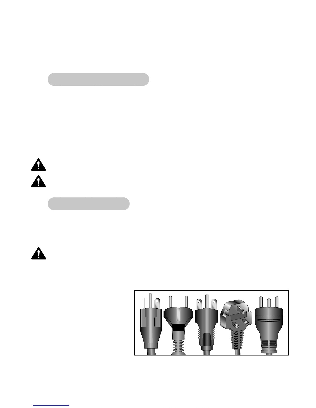
This treadmill is for use on a
grounded, dedicated circuit. Make
sure that the treadmill is connected
to an outlet having the same
confi guration as the plug. Do not
use a ground plug adapter to adapt
the power cord to a non-grounded
outlet.
115 VAC Euro Plug 220 VAC UK Danish
NEMA 5-20 CEE 7/7 NEMA 6-15 230 VAC IEC320
Safety
Page 1-1
Cybex 750T Treadmill Owner’s Manual
Important Safety Instructions
(Save These Instructions)
DANGER: To reduce the risk of electric shock, always unplug this treadmill from the electrical
outlet immediately after using it and before cleaning it.
WARNING: Serious injury could occur if these precautions are not observed. To reduce the risk
of burns, fi res, electric shock, or injury:
User Safety Precautions
Obtain a medical exam before beginning any exercise program. •
WARNING: Heart rate monitoring systems may be inaccurate. Over exercise may result in serious
injury or death. If you feel faint stop exercising immediately.
Stop exercising if you feel faint, dizzy, or experience pain and consult your physician. •
Obtain instruction before using.•
Read and understand the Owner’s Manual and all warnings posted on the unit before using. •
Read and understand emergency stop procedures.•
DO NOT • wear loose or dangling clothing while using the treadmill.
Keep all body parts, towels, water bottles and the like free and clear of moving parts. •
Place your feet on the two top steps when starting or stopping the treadmill. •
Use the treadmill handrails for support and to maintain balance.•
Keep children away from the treadmill. Teenagers and disabled persons must be supervised while •
using.
DO NOT • use the unit if you exceed 400 lbs. (181 kg). This is the rated maximum user weight.
Report any malfunctions, damage or repairs to the facility.•
Replace any warning labels if damaged, worn or illegible.•
Stop and place the treadmill at 0 degrees incline (level) after each use.•
Disconnect power before servicing.•
Facility Safety Precautions
Instruct all users on how to clip the e-stop clip onto their clothing and carefully test it prior to using the •
treadmill.
Instruct all users to use caution when mounting and dismounting the treadmill.•
Use a dedicated line when operating the treadmill. • NOTE: A dedicated line requires one circuit breaker
per unit.
Connect the treadmill to a properly grounded outlet only.•
DO NOT• operate electrically powered treadmills in damp or wet locations.
Safety
Page 1-2

Cybex 750T Treadmill Owner’s Manual
Keep the running belt clean and dry at all times.•
DO NOT • leave the treadmill unattended when plugged in and running. NOTE: Before leaving the
treadmill unattended, always wait until the treadmill comes to a complete stop and is level. Then, turn
all controls to the STOP or OFF position and remove the plug from the outlet. Remove the e-stop key
from the treadmill.
Immobilize the treadmill (when not in use) by removing the e-stop key.•
Inspect the treadmill for worn or loose components before each use. Do not use until worn or damaged •
parts are replaced.
Maintain and replace worn parts regularly. Refer to “Preventive Maintenance” section of Owner’s •
Manual.
DO NOT• operate the treadmill if: (1) the cord is damaged; (2) the treadmill is not working properly or
(3) if the treadmill has been dropped or damaged. Seek service from a qualifi ed technician.
DO NOT • place the cord near heated surfaces or sharp edges.
DO NOT • use the treadmill outdoors.
DO NOT • operate the treadmill around or where aerosol (spray) or where oxygen products are being
used.
Read and understand the Owner’s Manual completely before using the treadmill.•
Ensure all users wear proper footwear on or around all Cybex equipment.•
Set up and operate the treadmill on a solid, level surface. Do not operate in recessed areas or on •
plush carpet.
Provide the following clearances: 19.7 inches (0.5 m) at each side, 79 inches (2.0 m) at the back and •
enough room for safe access and passage at the front of the treadmill. Be sure your treadmill is clear
of walls, equipment and other hard surfaces.
DO NOT• attempt repairs, electrical or mechanical. Seek qualifi ed repair personnel when servicing. If
you live in the USA, contact Cybex Customer Service at 888-462-9239. If you live outside the USA,
contact Cybex Customer Service at 508-533-4300.
Use Cybex factory parts when replacing parts on the treadmill.•
DO NOT • modify the treadmill in any way.
DO NOT • use attachments unless recommended for the treadmill by Cybex.
Ensure all User and Facility Safety Precautions are observed.•
Safety
Page 1-3
Cybex 750T Treadmill Owner’s Manual
Carefully read and understand the following before using the 750T treadmill:•
Warning Decals•
Caution Decals•
To replace any worn or damaged decals do one of the following: Visit www.cybexinternational.com
to shop for parts online, fax orders to 508-533-5183 or contact Cybex Customer Service at 888-462-9239.
If you are located outside of the USA, call 508-533-4300. For location or part number of labels, see the
parts list and exploded-view diagram. This information can be found in the Service chapter in this manual
or on the Cybex web site at www.cybexinternational.com.
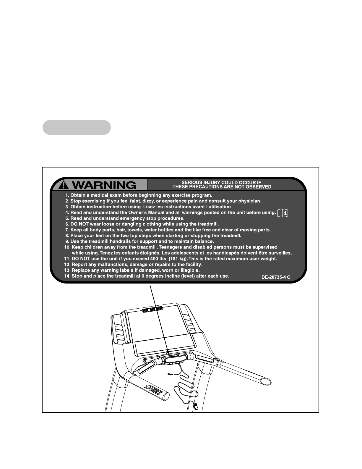
Warning Decals
Warning decals indicate a potentially hazardous situation, which, if not avoided, could result in death or
serious injury. The warning decals used on the Cybex 750T are shown below.
DE-20735-4
Warning
Safety
Page 1-4
Cybex 750T Treadmill Owner’s Manual
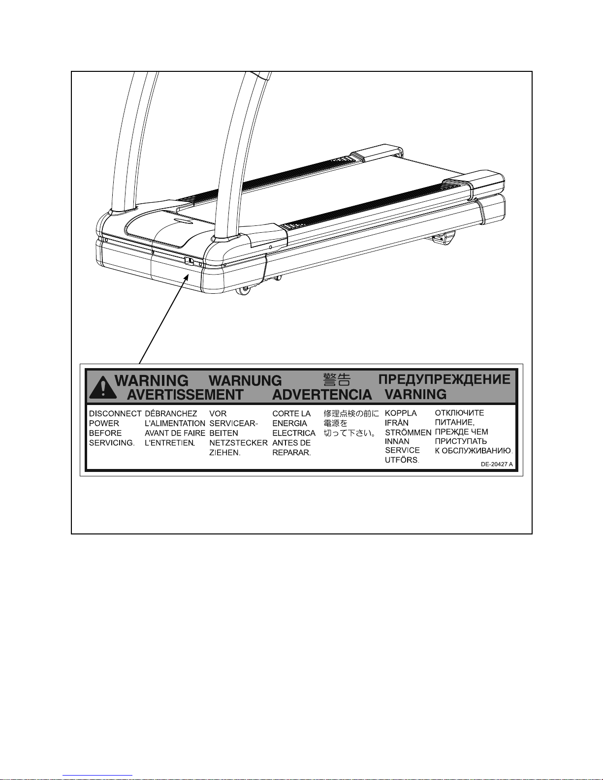
DE-20427
Warning Motor
Cover
Safety
Page 1-5
Cybex 750T Treadmill Owner’s Manual
Caution Decals
Caution decals indicate a potentially hazardous situation, which if not avoided, may result in minor or
moderate injury. There are no caution decals used on this unit. However, there are caution statements
listed in Chapters 2 and 5 of this manual. See Chapters 2 and 5.
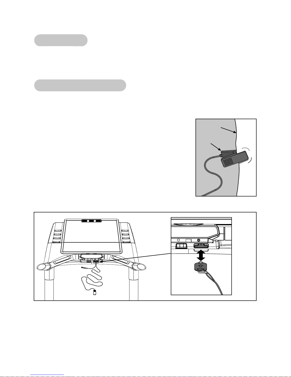
Emergency Stop Key (e-stop)
The e-stop key functions as an emergency stop. In an emergency situation, the e-stop key disengages
from the console and the treadmill will come to a stop. Before using the treadmill, clip the e-stop key as
described below.
1. Compress the spring and clip the e-stop clamp to your clothing.
Ensure the clip engages enough clothing so it does not fall off in an
emergency situation. See Figure 1. NOTE: Be sure the string is free
of knots and has enough slack for you to workout comfortably with the
e-stop key in place.
2. Without falling off the treadmill, carefully step backward until the
e-stop pulls out of the console. See Figure 2. NOTE: If the e-stop clip
falls off your clothing then the test has failed. Reclip the e-stop clip to
your clothing and repeat this step.
3. Replace the e-stop key. See Figure 2.
4. The treadmill is now ready to be used. NOTE: Ensure the the e-stop
clip is secured to your clothing at all times during use.
Clothing
Clip
Figure 1
Figure 2
5. After use, remove the e-stop key from the treadmill.
NOTE: The e-stop key can be removed to help prevent unauthorized use. Refer to the Stopping the
Treadmill section in the Operation chapter for more information about the e-stop key.
Safety
Page 1-6
Cybex 750T Treadmill Owner’s Manual
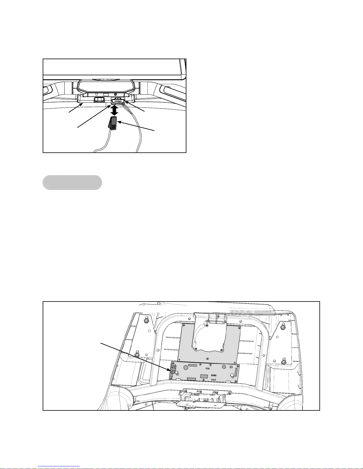
NOTE: When not in use store the e-stop clip on the storage tab located on the lower cover. See Figure 3.
Lower
Cover
Storage
Tab
Figure 3
E-Stop
Clip
CSAFE Ports
The 750T Treadmill has two CSAFE ports, one in the console for CSAFE devices that need access
there, and one under the base of the unit for running a network connection.
NOTE: The CSAFE standard defines a communication protocol and low-voltage DC power source
specific to the Fitness Equipment Industry. These RJ-45 phone jacks are provided for use ONLY
within the CSAFE protocol. For more information on the CSAFE standard, visit
www.fitlinxx.com/csafe. Not every connection carries both the communication and power
capability.
NOTE: The console CSAFE port inside the console contains the full implementation, with both network
communications and a standard CSAFE voltage (minimum 8.0 VDC) power source. The base
CSAFE port is accessible under the base of the treadmill and is for network communications
only and does not contain the DC power source. See Figures 4 and 5.
CSAFE Port
(Lower Socket)
Figure 4
Console CSAFE Port Location
Safety
Page 1-7
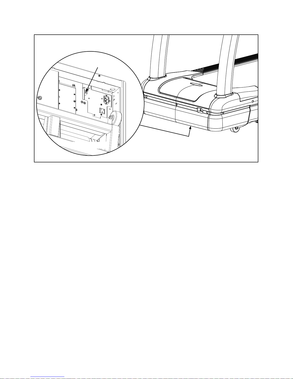
Base CSAFE Port Location
CSAFE
Port
Bottom View
Cybex 750T Treadmill Owner’s Manual
Figure 5
Safety
Page 1-8
Cybex 750T Treadmill Owner’s Manual
2 - Assembly and Setup
Warnings/Cautions
All warnings and cautions listed in this chapter are as follows:
WARNING: Use extreme caution when assembling the treadmill. Failure to do so could result in
injury.
WARNING: During this procedure STAY OFF THE RUNNING BELT! Stand with your feet on the two
steps.
CAUTION: A minimum of two people are required to lift, move and assemble this treadmill.
Always use proper lifting methods when moving heavy items.
Choosing and Preparing a Site
Before assembling the treadmill a suitable site must selected and have the proper electrical outlet power
available for optimum operation and safety. See the Electrical Power Requirements section (located on
the next page) for direction in locating the treadmill’s voltage requirements.
The area selected for the treadmill should be well lit and well ventilated. Locate the treadmill on a
structurally sound and level surface (do not place in recessed areas or on plush carpet) a few feet away
from walls and other equipment. Each side of the treadmill should have a 19.7” (0.5 m) minimum space.
Behind the treadmill should be 79” (2.0 m) minimum of space. Allow enough clearance for safe access
and passage during use of the machine. If the treadmill is to be located above the fi rst fl oor, place it near
or above major support beams. If the area has a heavy, plush carpet, the airfl ow around the base of the
machine may be restricted or the carpeting may interfere with the moving parts. To protect the carpeting
and the machinery, place a 3/4” (1.9 cm) thick wood base under the treadmill.
Do not install the treadmill in an area of high humidity, such as in the vicinity of a steam room, sauna,
indoor pool, or outdoors. Exposure to extensive water vapor, chlorine, and/or bromine could adversely
affect the electronics as well as other parts of the machine.
Assembly
and
Setup
Page 2-1
Cybex 750T Treadmill Owner’s Manual
Electrical Power Requirements
The power requirements for this treadmill are a grounded, dedicated circuit rated for one of the following:
100 VAC, 50/60 Hz, 20A•
115 VAC, 60 Hz, 20A•
220 VAC, 60 Hz, 15A•
230 VAC, 50 Hz, 15A•
230 VAC, 50 Hz, 13A, UK•
Contact a qualifi ed electrician to ensure the power supply complies with local building codes.
Do not use a ground plug adapter to adapt the 3-prong power cord plug to a non-grounded electrical
outlet. Do not use an extension cord.
Assembling the Treadmill
WARNING: Use extreme caution when assembling the treadmill. Failure to do so could result in
injury.
CAUTION: A minimum of two people are required to assemble this treadmill.
Tools Required
1/2” Socket wrench with a 4” extension•
1/2” Box end wrench, 12 point•
9/16” Socket wrench with a 4” extension•
Phillips screwdriver•
NOTE: The words “left” and “right” denote the treadmill user’s orientation.
1. Read and understand all instructions thoroughly before assembling the treadmill.
NOTE: Each step number in the assembly instructions tells you what you will be doing. The lettered
steps following each step number describe the procedure required. Do not continue with step 2
until you have carefully read all of the assembly instructions.
2. Verify you have received the correct package.
Read the sticker on the outside of the box and verify that the model number, color and voltage are A.
what you ordered. NOTE: During step 3 and 5 you will verify that the contents of the box match
the sticker.
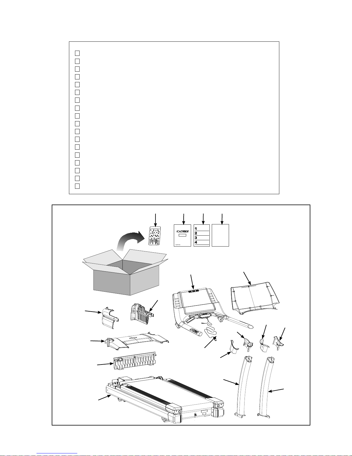
3. Unpack and verify the contents of the boxes.
Lift up and remove the cardboard sleeve that surrounds the treadmill. A.
Verify the following items are present. Check off ( B. ) each item as you fi nd it. See Figure 1. If any
of the parts are missing contact Cybex Customer Service.
Assembly
and
Setup
Page 2-2
Cybex 750T Treadmill Owner’s Manual
Item Qty Part Number Description
1 1 Varies Base assembly
2 1 Varies Console assembly
3 1 AF-19921 Upright, Left
4 1 AF-19922 Upright, Right
5 1 AX-20383 Motor cover, Top
6 1 PL-20264 Motor cover, Front
7 1 PL-20262 Motor cover, Left (in box)
8 1 PL-20263 Motor cover, Right (in box)
9 1 PL-20355 Upright cover, Outer, Left (in box)
10 1 PL-20211 Upright cover, Inner, Left (in box)
11 1 PL-20356 Upright cover, Inner, Right (in box)
12 1 PL-20357 Upright cover, Outer, Right (in box)
13 1 PL-20210 Console cover, Back
14 1 AX-20454 Hardware pack (in box)
15 1 LT-20406-4 Owner’s Manual (in box)
16 1 LT-20404 Assembly poster
17 1 LT-20405 Warranty sheet
18 1 AX-20552 Assembly, E-stop lanyard
#7
#5
#6
#14
#8
#15
#2
#16
#18
#9
#17
#3
#10
#13
#11
#12
#4
#1
Figure 1
Assembly
and
Setup
Page 2-3
Cybex 750T Treadmill Owner’s Manual
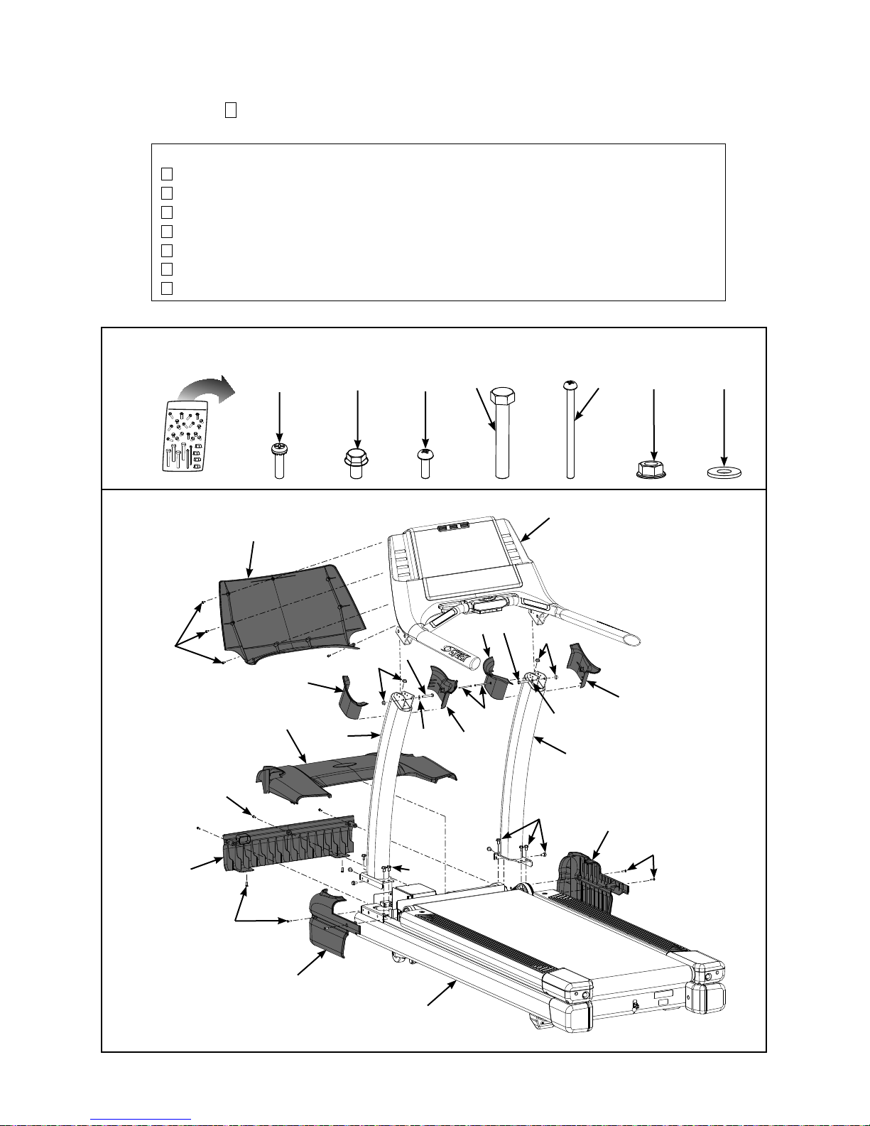
C. Check off () each item in the hardware pack as you fi nd it. See Figure 2.
Item Qty Part Number Description
19 9 HS-16939 Screw, SEMS, 10-32 x .75”, PNHD, BLK
20 10 HS-16929 Bolt, Whiz Lock, 3/8-16 x .625”, HXHD
21 9 HS-15706 Screw, 8/16 x .50”, PNHD, STL, BLK
22 2 HS-41050 Bolt, 5/16-18 x 2.25”, HXHD
23 2 HS-20361 Screw, SLFTP, 8/16 x 2.5”, Plastite, BLK ZN
24 4 HN-42063 Nut, 5/16-18, Flanged, SS
25 2 HW-00189 Washer, Flat 5/16”
Hardware
#21
#19
#13
#19
#5
#9
#3
#20
#24
#21
#22
#25
#22
#11
#10
#23
#22
#24
#20
#2
#25
#4
#23
#8
#12
#24
#25
#6
#19
#7
Assembly
and
Setup
Figure 2
Page 2-4
#19
#20
#1
Cybex 750T Treadmill Owner’s Manual
CAUTION: A minimum of two people are required to lift, move and assemble this treadmill.
Always use proper lifting methods when moving heavy items.
4. Lift and move the treadmill.
At least two people should lift and move the treadmill to a level location where you intend to leave A.
it. Use proper lifting methods.
5. Verify the model and voltage.
Verify that you have the correct model and voltage by looking at the serial number label located A.
at the rear of the unit.
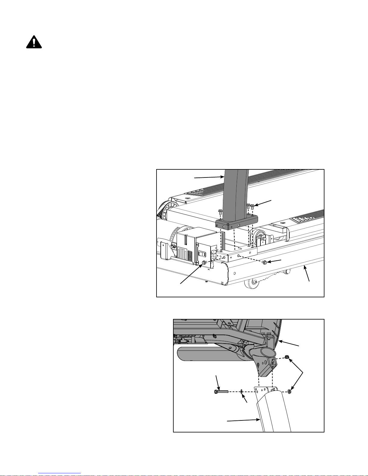
6. Install the uprights.
Locate the left upright (#3) and fi ve bolts, 3/8-16 x .625” (#20).A.
Carefully place the left upright (#3) on the base assembly (#1) as shown. See Figure 3.B.
Using a 9/16” Socket wrench, C.
partially tighten each of the fi ve
#3
bolts, 3/8-16 x .625” (#20). See
Figure 3.
#20
Repeat steps 6A to 6C for the D.
right upright (#4).
7. Install the console assembly to
the uprights.
Locate the console assembly A.
(#2), bolt 5/16-18 x 2.25” HXHD
(#22), washer (#25) and two
nuts (#24). See Figure 4.
NOTE: Do not pinch or damage display
cable when installing console
assembly.
B. Place the console assembly
Figure 3
(#2) in position on the left upright
(#3). See Figure 4.
C. Using a 1/2” box end wrench, partially
tighten the bolt 5/16-18 x 2.25”,
HXHD (#22), washer (#25) and two
nuts (#24). See Figure 4.
#20
#22
#20
#1
#2
#24
Figure 4
#25
#3
Assembly
and
Setup
Page 2-5
Cybex 750T Treadmill Owner’s Manual
D. Repeat steps 7A to 7C for the right upright.
E. Using a 1/2” box end wrench, fully tighten the two bolts, 5/16-18 x 2.25”, HXHD (#22) and four
nuts (#24) securing the console assembly to the uprights. See Figure 4.
F. Using a 9/16” Socket wrench, fully tighten the ten bolts, 3/8-16 x .625” (#20) securing the uprights
to the base assembly (#1). See Figure 3.
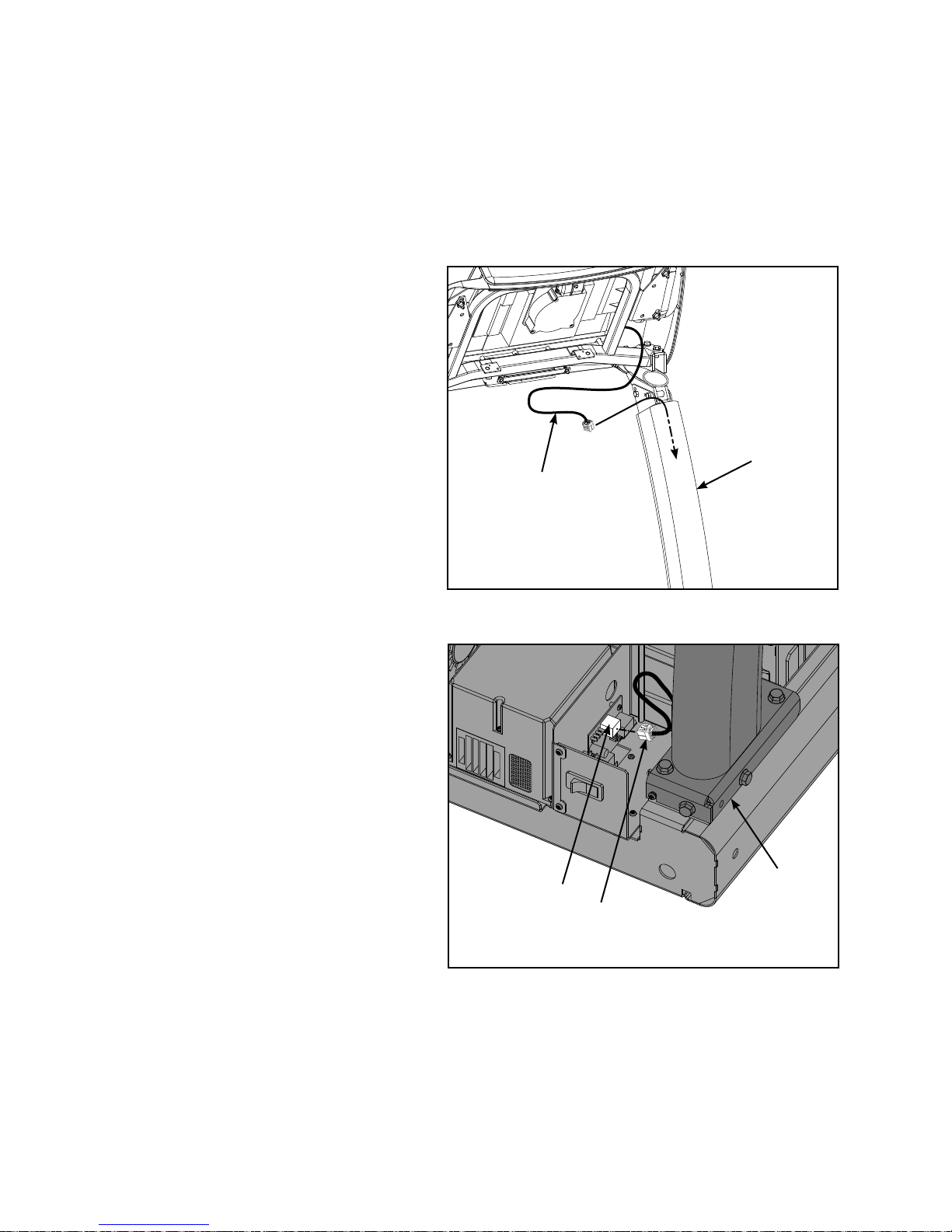
8. Install the Display Cable.
NOTE: Do not pinch or damage display cable
when installing.
Locate the display cable exiting the A.
back of the console assembly.
Insert the display cable into the top of B.
the left upright (#3) until it exits at the
base of the upright (#3). See Figures
5 and 6.
Plug the display cable, located at the C.
bottom of the upright assembly (#3)
Display
Cable
#3
into the hub board connector J3. See
Figure 6.
NOTE: If installing the A/V option, refer to
the 750T A/V bracket installation
instructions (supplied with the A/V
bracket).
Figure 5
Hub Board
Connector J3
Figure 6
#3
Display
Cable
Assembly
and
Setup
Page 2-6
Cybex 750T Treadmill Owner’s Manual
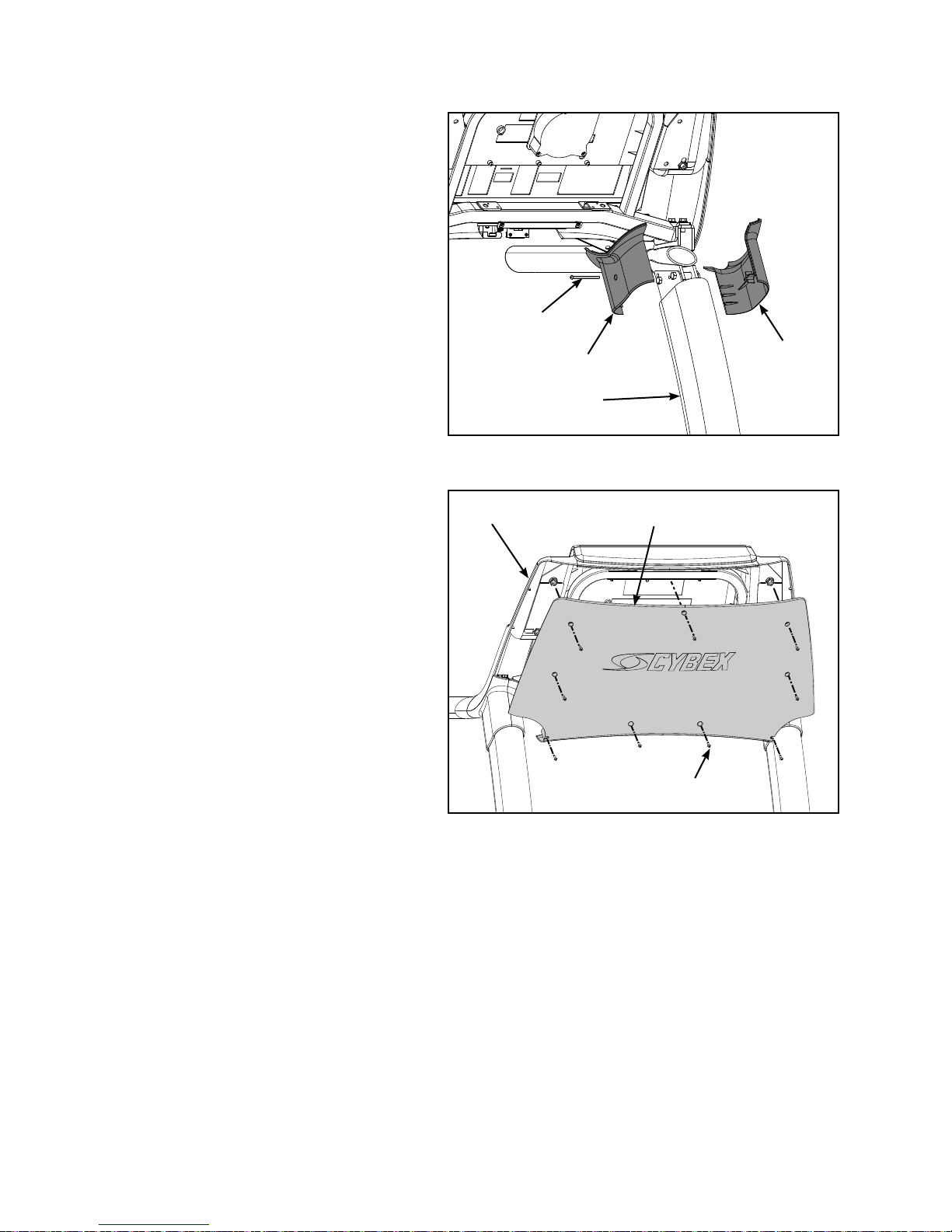
9. Attach the upright covers (four pieces).
Locate the outer left upright cover A.
(#9), inner left upright cover (#10)
and one screw 8/16 x 2.5” (#23).
See Figure 7.
Place the two upright covers in B.
place over the left upright (#3). See
Figure 7.
Insert the screw 8/16 x 2.5” (#23) C.
into the inner left upright cover
(#10) and secure using a Phillips
screwdriver. See Figure 7.
Repeat steps 9A to 9C for the right D.
side.
10. Attach the back console cover.
Locate the back console cover (#13) A.
and nine screws 8/16 x .50” (#21).
See Figure 8.
While being sure not to pinch any B.
cables, use a Philips screwdriver to
secure the nine screws 8/16 x .50”
(#21) that hold the back console cover
(#13) to the console assembly (#2).
See Figure 8.
Figure 7
#2
#23
#9
#10
#3
#13
#21 (9)
Figure 8
Assembly
and
Setup
Page 2-7
Cybex 750T Treadmill Owner’s Manual
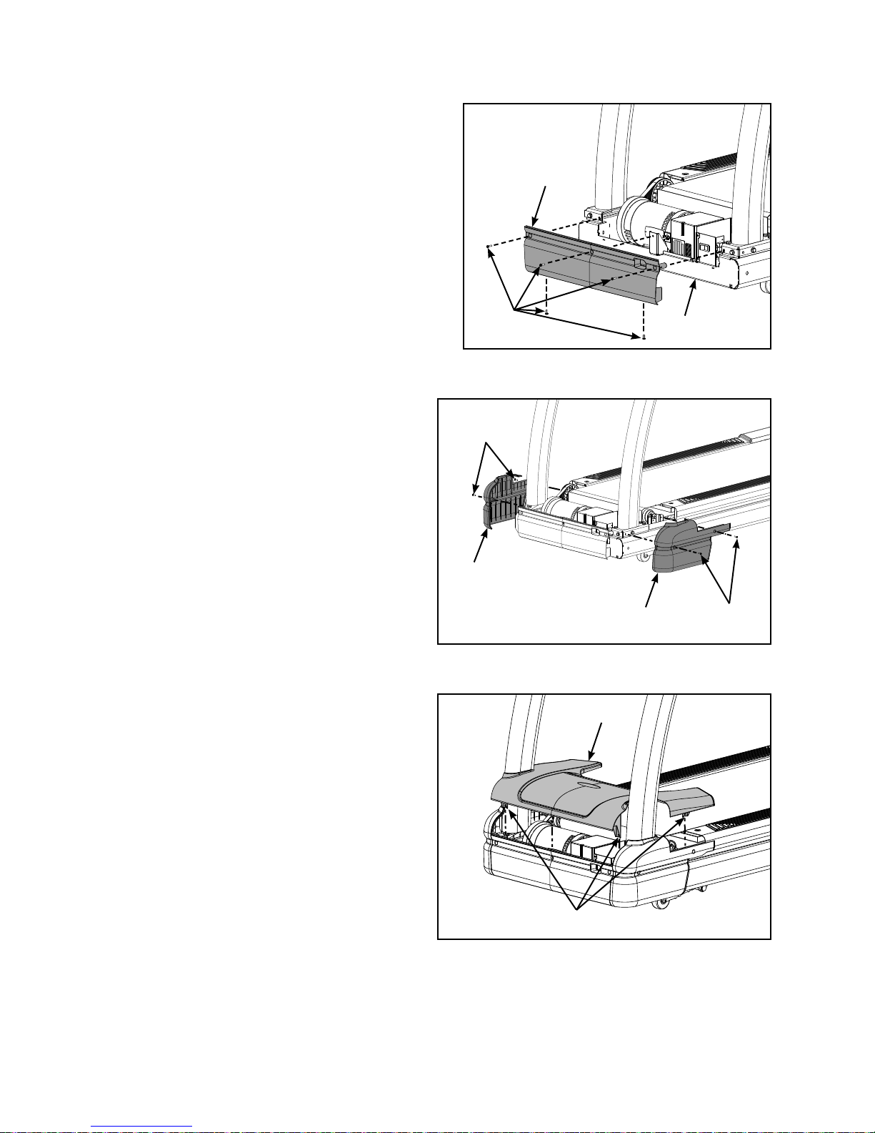
11. Attach the motor covers (four pieces).
A. Locate the front motor cover (#6) and fi ve
screws 10-32 x .75” (#19). See Figure 9.
NOTE: Elevate or tip the treadmill on it’s side to install
the two lower screws (#19).
B. Using a Phillips screwdriver partially tighten
the front motor cover (#6) to the base (#1)
with fi ve screws 10-32 x .75” (#19). See
Figure 9.
#6
C. Locate the left motor cover (#7) and four
screws 10-32 x .75” (#19)
D. Using a Phillips screwdriver, partially tighten
the left motor cover (#7) with two screws
10-32 x .75” (#19). See Figure 10.
E. Repeat steps 11C and 11D for the right
side.
F. Locate the motor cover top (#5).
G. Place the motor cover top (#5) into
position by aligning the four tabs over the
front and side cover screws. See
Figure 11.
NOTE: If motor cover top does not fi t properly,
loosen the front and side cover screws as
needed.
H. Using a Phillips screwdriver, fi nish
tightening the fi ve front cover screws and
four side cover screws. Be sure the screws
are securing the motor cover’s tabs. See
Figure 11.
#19
Figure 9
#19
#8
Figure 10
#5
#7
#1
#19
12. Level the treadmill.
Confi rm that the treadmill is on a level A.
surface.
Assembly
and
Setup
Page 2-8
Tabs
Figure 11
Cybex 750T Treadmill Owner’s Manual
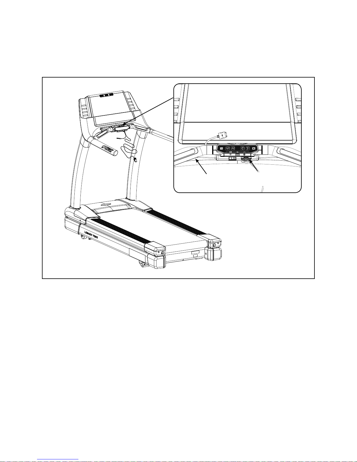
13. Attach emergency stop key.
Confi rm that the emergency stop key is in place in the bottom of the console handrail. See A.
Figure 12. NOTE: The treadmill will not run without the key in place.
Figure 12
14. Visually inspect the treadmill.
Carefully examine the treadmill to ensure that the assembly is correct and complete.A.
Console
Handrail
Emergency
Stop Key
Assembly
and
Setup
Page 2-9
Cybex 750T Treadmill Owner’s Manual
WARNING: Be sure that all electrical requirements are met as indicated in the specifi cations at
the front of the manual and at the beginning of this chapter prior to proceeding.
Testing the Treadmill Operation
Use the following instructions to test the full speed and incline range of the treadmill and to check the belt
for proper operation.
CAUTION: During this procedure STAY OFF THE RUNNING BELT! Stand with your feet on the two
steps.
NOTE: Cybex recommends that the treadmill be unplugged or the on/off (I/O) power switch turned off (O)
when it is not in use.
1. Without anyone on the treadmill, plug the power cord into a power outlet from a grounded, dedicated
circuit as described under Electrical Requirements in this chapter.
NOTE: Ensure the power cord is not being pinched under the front of the treadmill.
2. Locate the on/off (I/O) power switch in the front motor cover of the treadmill. Toggle it to the on
position (I).
3. The control panel will light up and be in the Dormant Mode.
4. Press the Quick Start key. The treadmill begins a countdown “BELT START IN 3...2...1” and sounds
a tone for each count. After it reaches one (1), the treadmill gives a longer tone and then begins
accelerating the belt to reach 0.5 mph (0.8 kph).
5. The lower left display will show the incline then time and the lower right display will show the actual
speed.
6. Press and hold down the Speed + key until the treadmill reaches a speed of approximately 4 mph
(6.4 kph), as indicated on the display.
7. Observe the belt to see that it is running properly; it should stay centered in the middle of the deck. If
you have problems with the running belt operation, see Running Belt Adjustments in the Preventive
Maintenance chapter.
8. Run the treadmill through its full speed range. First press the Speed + key until the treadmill reaches
its highest speed. Then press the Speed - key until the treadmill is back to 0.5 mph (0.8 kph).
9. As you press the Incline
or speed.
10. When the treadmill reaches the set incline and speed, the displays will remain steadily illuminated to
indicate that the desired settings have been reached.
11. Run the treadmill through its full % grade range. Press the Incline
its highest grade (15%). Then press the Incline key until the treadmill reaches -3% grade.
or Speed + - keys, the respective displays will show the actual incline
key until the treadmill reaches
12. Press the Stop key to stop the running belt, end the workout review and return the display to
Dormant Mode.
Assembly
and
Setup
Page 2-10

Cybex 750T Treadmill Owner’s Manual
Setup
1. While in Dormant Mode enter Set Up Mode by pressing the following buttons on the keypad
Clear 750 and then press the Enter key. You will now be in the set up menu.
2. Press the Speed + and - keys to scroll through the set up options. Press the Enter key to edit options,
change values with the Incline
selection and return to the set up menu. Press the STOP key to exit to Dormant Mode. Press the
CLEAR key to reset to the previous stored value, and exit back to the menu. The set up options are
displayed in the following order:
Language (Language):
This selects the language displayed in the text area of the console. Language choices are:
ENGLISH (Default) •
GERMAN•
FRENCH•
SPANISH•
JAPANESE•
SWEDISH•
RUSSIAN•
DANISH•
and keys or the Speed + and - keys. Press Enter to save your
Units (UNITS):
Choices are “ENGLISH (LB/MPH)” or “METRIC (KG/KPH)” measurements. English is the default.
Frequency (FREQUENCY):
This is the frequency of the power line that supplies power to your treadmill. The default setting is 60 Hz.
NOTE: If you have an English console and a 50 Hz power line frequency , then you must change the default
setting from 60 Hz to 50 Hz for the proper elevation frequency .
Clock Style (HH:MM / MM:DD:YY or DD:MM:YY):
The 750T features a clock and calendar. The clock can be displayed in a 12 or 24 hour format. The
calendar date fomat can be displayed as Month-Day–Year (US) or Day–Month–Year (EU).
“12HR US DATE”
“24HR EURO DATE”
“12HR EURO DATE”
“24HR US DATE”
Current Time (HH:MM):
The 750T features a clock that displays the current time. Examples for 2:57 PM on May 10, 2007.
12HR US DATE “02:57P 5/10/2007”
24HR EURO DATE “14:57 10-05-2007”
12HR EURO DATE “02:57P 10-05-2007”
24HR US DATE “14:57 5/10/2007”
Assembly
and
Setup
Page 2-11

Cybex 750T Treadmill Owner’s Manual
Default Time (DEFAULT TIME):
This is the default time for time based programs if a user does not re-set Time. For example, if you press
Time you can decrease or increase the set workout time up to the amount that the Max time is set.
Choices are 10, 20, 30, 60 and 90 minutes. Default is 30 minutes.
Review Time (REVIEW TIME):
This is the Review Time for which the user’s workout results are displayed at the end of a workout.
Choices are 0:10, 0:20, 0:30, 1:00 and 5:00 minutes. Default is 20 seconds.
Max Time/Time Zones (MAX TIME = MINUTES, ZONED OR OFF):
This is the maximum amount of time the treadmill can run per user workout session. You can limit the
users time or choose ‘OFF’ to disable the Max Time. Valid choices for Max Time are OFF, 20, 30, 40, 50,
60, 90 and 120 minutes or ZONED. For ZONED, you can defi ne a user maximum session time based on
four time zones. This allows limiting use only during busy times of the day.
This is how ZONED is confi gured from the factory:
ZONE1 5:01A 60
ZONE2 9:01A OFF
ZONE3 4:01P 60
ZONE4 9:00P OFF
The maximum session time is limited to 60 minutes from 5AM - 9AM and from 4PM to 9PM in this
example, with all other times unlimited. The zone start/stop time and the time limit in each zone can be
modifi ed to suit your needs.
Pause Time (PAUSE TIME):
This is how long the treadmill retains and displays your current workout data during a pause in the
workout. Choices include: Off; 1 minute; 5 minutes; and 10 minutes; default is Off.
WARNING: It is strongly suggested to not allow any user on the treadmill without adequate
instruction. The use of a treadmill at high speeds can be dangerous and potentially
result in injury. To avoid injury no user should be allowed to use the treadmill at a
speed that exceeds their level of ability.
The 750T Treadmill has been programmed to have a default maximum speed of 12.4
mph from the factory. As the owner of this treadmill you may change the default
setting for maximum speed up to 15 mph. Please be aware that higher speeds have
higher risk and if a user exceeds their ability, they can potentially loose coordination
that can result in injury.
The e-stop clip should be worn at all times.
Max Speed (MAX SPEED):
This is the maximum speed the treadmill will run. Choices are between .5 and 15.6 MPH (0.8 to
25.1 kph). Default MAX SPEED is set at 12.4 MPH (20.0 KPH).
Max Incline (MAX INCLINE):
This is the maximum elevation the treadmill will incline. Choices are between 0 and 15 percent grade.
NOTE: Setting both the Min and Max incline to 0 percent will disable the elevation.
Min Speed (MIN SPEED):
This is the minimum speed the treadmill will run. Choices are between .5 and 1.0 MPH (0.8 to 1.6 KPH).
Min Incline (MIN INCLINE):
This is the minimum elevation the treadmill will decline. Choices are between -3 and 0 percent grade.
NOTE: Setting both the Min and Max incline to 0 percent will disable the elevation.
Assembly
and
Setup
Page 2-12

Cybex 750T Treadmill Owner’s Manual
Sound (TONE - ON/OFF):
This option will enable or disable the beeper by toggling it on/off. Default is On.
Dormant Display Option (DORMANT STYLE):
This defi nes what is displayed in Dormant mode. Valid Choices for Dormant Display are:
0 – DEFAULT 1 – TEXT MSG - Not Applicable.
2 – OUT OF ORDER - Out of Order message.
3 – CLOCK - Time clock.
4 – PROFILES - Displays program profi les.
Lock Combination (LOCK CODE).
This feature will allow the Lock Combination (PIN) to be changed. It requires the correct PIN number to
be entered fi rst before allowing any changes.
The PIN numbers will be entered using the keypad. If an incorrect PIN number is entered, the number will
blink once and revert back to underscores. If a valid PIN number is entered, blink the ON or OFF (default)
text (whichever was previously stored) and allow the Speed Control Key to toggle it.
Custom Programs - (SAVE PROGRAM).
The ability to SAVE a workout session as a custom program during Review is enabled or disabled here.
If disabled, the SAVE button will not be active during Review. The text area will display Save Program
On or Save Program OFF (default).
Remember: You must press Enter after changing a value for that value to be stored.
3. To exit Set Up Mode press the Stop key once.
Your treadmill is now ready for use. Follow the instructions in the Operation chapter to learn how to operate
the treadmill. You should begin with walking speeds first, to be sure everything is functioning properly.
Assembly
and
Setup
Page 2-13
 Loading...