

Page 1

Cybex Modular
www.cybexinternational.com
Owner’s and Service Manual
Strength Systems
Part Number 55620 H
Page 2

Page 3

Cybex Modular
Owner’s and Service Manual
Strength Systems
Part Number 55620 H
DISCLAIMER: Cybex International, Inc., makes no representations or warranties regarding the contents of this manual. We reserve the right to
revise this document at any time or to make changes to the product described within it without notice or obligation to notify any person of
such revisions or changes.
© Copyright 2009 Cybex International, Inc. All rights reserved.
Printed in the United States of America.
10 Trotter Drive Medway, MA 02053 • 508-533-4300 • FAX 508-533-5183
www.cybexinternational.com • techhelp@cybexintl.com • techpubs@cybexintl.com • 55620 H • July 2009
Page 4

Page 5

i Table of Contents
1 Safety
Safety......................... 1-1
Warning/Caution Decals .......... 1-2
Regular Maintenance Activities ..... 1-21
Using Proper Form .............. 1-21
2 Exercises
(Lower Body)
Seated Leg Press -5652/5322 ..... 2-1
Leg Extension/Leg Curl -
5653/5607 .................... 2-3
(Upper Body)
Low Row (5651/5302) ............ 2-5
Lat Pulldown - 5601.............. 2-7
Chest Press - 5640 .............. 2-9
Pressing Station - 5647/5306 ...... 2-11
Shoulder Press - 5639 ........... 2-13
Tricep Pressdown - 5603.......... 2-15
Tricep Extension - 5641........... 2-17
Arm Curl - 5644 ................. 2-19
(Multi Station)
Cable Crossover -
5648/5649/5650/5311 ........... 2-21
Cable Column -
5605/5633/5315/5316 ........... 2-23
Assisted Chin-Up/Dip - 5611 and
SS Assisted Chin-Up/Dip - 5345 . . 2-25
3 Customer Service
Contacting Service............... 3-1
Ordering Parts .................. 3-1
Returning Goods ................ 3-2
Damaged Parts ................. 3-3
4 Assembly
Weight Stack Installation .......... 4-1
Handle Rack ................... 5631
Modular Mover ................. 5632
Seated Leg Press ............... 5652/5322
Leg Extenstion/Leg Curl .......... 5653/5307
Table of Contents
Page i
5 Maintenance
Daily Procedures ................ 5-1
Weekly Procedures .............. 5-4
Yearly Procedures ............... 5-6
“As Required” Procedures......... 5-6
6 Assembly and Service
Modular Center Post ............. 5600
Tandem Center Post ............. 5629
Lat Pulldown ................... 5601
Tricep Pressdown ............... 5603
45 Degree Back Extension ........ 5608
Bent Leg Abdominal Board ........ 5610
Blank ......................... 5624
Leg Raise Chair ................. 5645
Cable Column .................. 5605
Cable Column .................. 5633
Cable Column .................. 5315/5316
Assist Dip/Chin ................. 5611
Single Station Dip/Chin ........... 5345
Shoulder Press ................. 5639
Chest Press .................... 5640
Tricep Extension ................ 5641
Arm Curl....................... 5644
Low Row ...................... 5651/5302
Pressing Station ................ 5647/5306
Cable Crossover ................ 5648/5649
5650/5311
Seated Leg Press ............... 5652/5322
Leg Extension/Leg Curl ........... 5653/5307
Page 6

Page 7

Page 1-1
1 - Safety
Safety
Read the Owner’s Manual carefully before assembling, servicing or using the equipment.
It is the responsibility of the facility owner and/or owner of the equipment to instruct users on
proper operation of the equipment and review all labels.
! WARNING: Serious injury could occur if these safety precautions are not observed:
USER SAFETY PRECAUTIONS
• Obtain a medical exam prior to beginning an exercise program.
• Read and understand warning labels and user manual prior to exercising. Obtain
instruction prior to use.
• Keep body and clothing free from and clear of all moving parts.
• Inspect machine prior to use. DO NOT use if it appears damaged or inoperable.
• DO NOT attempt to fix a broken or jammed machine. Notify floor staff.
• Use the machine only for the intended use. DO NOT modify the machine.
• Be sure that the weight pin is completely inserted. Use only the pin provided by the
manufacturer. If unsure seek assistance.
• Never pin the weights in an elevated position. DO NOT use the machine if found in this
condition. See assistance from floor staff.
• Children must not be allowed near these machines. Teenagers must be supervised.
• DO NOT use if guards are missing or damaged.
• DO NOT use dumbbells or other incremental weights, except those provided by the
manufacturer.
• Inspect all cables and belts and connections prior to use. DO NOT use if any components
are worn, frayed or damaged.
• DO NOT remove any labeling from equipment. Replace any damaged labels.
• Stop exercising if you feel faint, dizzy or experience pain at any time while exercising and
consult your physician.
Cybex Modular Owner’s Manual
Page 8

Cybex Modular Owner’s Manual
Facility Safety Precautions
• Read the Owner’s Manual carefully before assembling, servicing or using the equipment.
• Securely anchor each machine to the floor using the anchor holes provided in each
machine.
• Make sure that each machine is set up and operated on a solid level surface. Do not
install equipment on an uneven surface.
• Make sure that all users are properly trained on how to use the equipment.
• Make sure there is enough room for safe access and operation of the equipment.
• Perform regular maintenance checks on the equipment. Also pay close attention to all
areas most susceptible to wear, including (but not limited to) cables, pulleys, belts and
grips.
• Immediately replace worn or damaged components. If unable to immediately replace worn
or damaged components then remove from service until the repair is made.
• Use only Cybex supplied components to maintain/repair the equipment.
• Keep a repair log of all maintenance activities.
• Inspect all cables and belts and connections prior to use. DO NOT use if any components
are worn, frayed, or damaged.
NOTE: It is the sole responsibility of the user/owner or facility operator to ensure that regular
maintenance is performed.
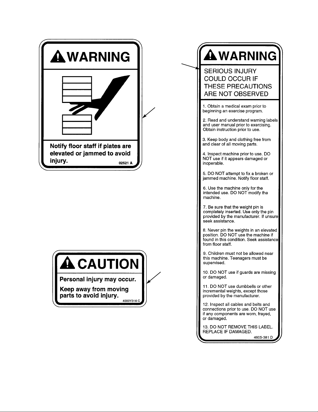
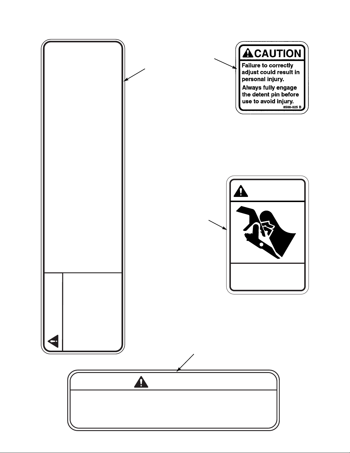
Warning/Caution Decals
Warning decals indicate a potentially hazardous situation, which, if not avoided, could result
in death or serious injury.
Caution decals indicate a potentially hazardous situation, which, if not avoided, could result in
minor or moderate injury.
The warning and caution decals are shown on the following page. The diagrams following the
decals show where each decal is located.
Page 1-2
NOTE: Cybex is not responsible for the actual anchoring of equipment. Consult
with a professional contractor.
NOTE: Use fasteners having a minimum of 500 lbs. tensile capacity (3/8” grade 2
bolts or better).
NOTE: If legs/frame does not contact surface, DO NOT pull down with anchors.
Shim any leg or frame not in contact with surface using flat washers.
Page 9
Cybex Modular Owner’s Manual
Page 1-3
A
B
C
Page 10
Cybex Modular Owner’s Manual
Page 1-4
CAUTION
350 LBS MAXIMUM LOAD
DO NOT EXCEED MAXIMUM CROSS TUBE LOAD.
PERSONAL INJURY MAY RESULT.
5649-329 A
G
E
.
D
F
10. DO NOT use if guards are missing
or damaged.
11. DO NOT use dumbbells or other
incremental weights, except those
provided by the manufacturer.
12. Inspect all cables and belts and
connections prior to use. DO NOT use
if any components are worn, frayed,
or damaged
4800-381 C
13. DO NOT REMOVE THIS LABEL.
REPLACE IF DAMAGED.
6. Use the machine only for the
intended use. DO NOT modify the
machine.
7. Be sure that the weight pin is
completely inserted. Use only the pin
provided by the manufacturer. If unsure
seek assistance.
2. Read and understand warning
labels and user manual prior to
exercising. Obtain instruction
1. Obtain a medical exam prior to
beginning an exercise program.
prior to use.
WARNING
SERIOUS INJURY
9. Children must not be allowed near
this machine. Teenagers must be
8. Never pin the weights in an elevated
position. DO NOT use the machine if
found in this condition. Seek assistance
4. Inspect machine prior to use. DO
3. Keep body and clothing free from
NOT use if it appears damaged or
and clear of all moving parts.
COULD OCCUR IF
THESE PRECAUTIONS
ARE NOT OBSERVED
supervised.
from floor staff.
inoperable.
5. DO NOT attempt to fix a broken or
jammed machine. Notify floor staff.
CAUTION
Keep away from moving
parts. Failure to do so could
result in personal injury.
8500-026 A
Page 11
Cybex Modular Owner’s Manual
Page 1-5
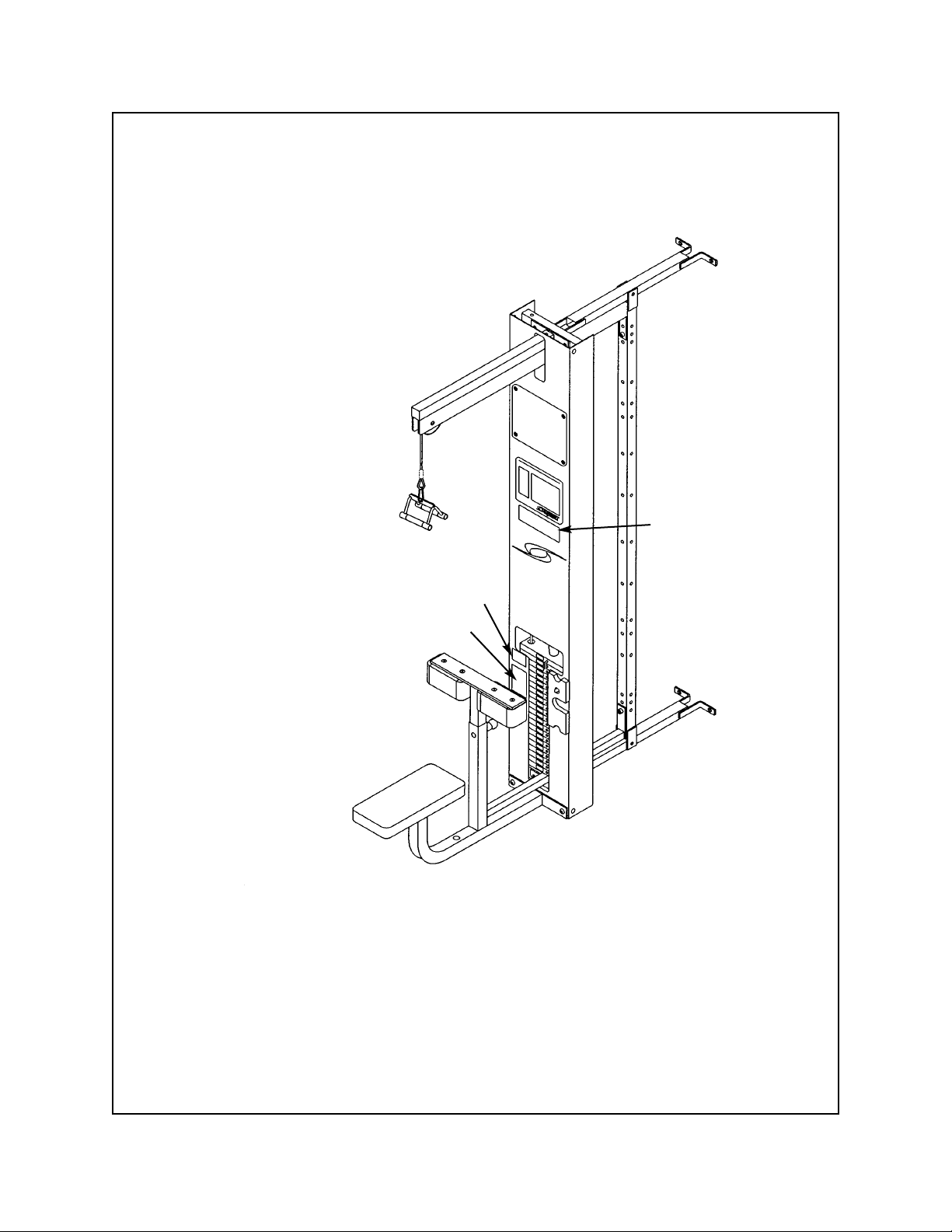
Lat Pulldown - 5601
B
D
A
A. Warning Decal ................... 02521
B. Caution Decal .................... 4000Y316
D. Warning Decal.................... 4800-381
DESCRIPTION PART NO.
Page 12
Cybex Modular Owner’s Manual
Page 1-6
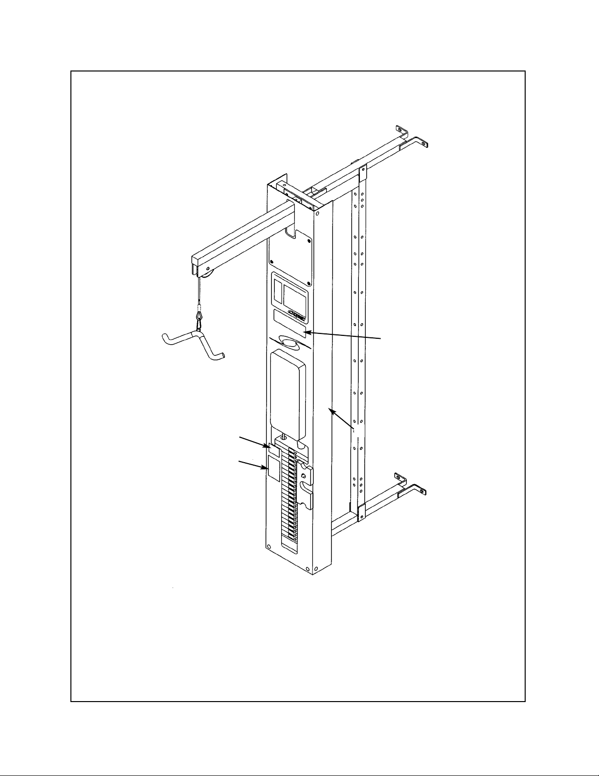
Tricep Pressdown - 5603
D
B
B
A
A. Warning Decal ................... 02521
B. Caution Decal .................... 4000Y316
D. Warning Decal.................... 4800-381
DESCRIPTION PART NO.
Page 13
Cybex Modular Owner’s Manual
Page 1-7
Cable Column - 5605/5315/5316/5633
B
A
D
A. Warning Decal ................... 02521
B. Caution Decal .................... 4000Y316
D. Warning Decal.................... 4800-381
DESCRIPTION PART NO.
5605 - Modular without Booms
5633 - Modular with Booms
5315 - Free Standing without Booms
5316 - Free Standing with Booms
Page 14

Cybex Modular Owner’s Manual
Page 1-8
Assist Chin Up/Dip - 5611
D
A
A. Warning Decal ................... 02521
B. Caution Decal .................... 4000Y316
D. Warning Decal.................... 4800-381
DESCRIPTION PART NO.
B
5345 - Single Station Chin-Up/Dip
Page 15
Cybex Modular Owner’s Manual
Page 1-9
D
Low Row - 5651 and 5302
A
A. Warning Decal ................... 02521
B. Caution Decal .................... 4000Y316
D. Warning Decal.................... 4800-381
DESCRIPTION PART NO.
B
Page 16

Cybex Modular Owner’s Manual
Page 1-10
Shoulder Press - 5639
A
B
D
A. Warning Decal ................... 02521
B. Caution Decal .................... 4000Y316
D. Warning Decal.................... 4800-381
DESCRIPTION PART NO.
Page 17

Cybex Modular Owner’s Manual
Page 1-11
C
Chest Press - 5640
B
A
A. Warning Decal ................... 02521
B. Caution Decal .................... 4000Y316
C. Warning Decal.................... 4605-381
DESCRIPTION PART NO.
Page 18
Cybex Modular Owner’s Manual
Page 1-12
Tricep Extension - 5641
D
B
A
A. Warning Decal ................... 02521
B. Caution Decal .................... 4000Y316
D. Warning Decal.................... 4800-381
DESCRIPTION PART NO.
Page 19
Arm Curl - 5644
B
A
D
Cybex Modular Owner’s Manual
Page 1-13
A. Warning Decal ................... 02521
B. Caution Decal .................... 4000Y316
D. Warning Decal.................... 4800-381
DESCRIPTION PART NO.
Page 20
Cybex Modular Owner’s Manual
Page 1-14
Pressing Station - 5647 and 5306
D
A
B
A. Warning Decal ................... 02521
B. Caution Decal .................... 4000Y316
D. Warning Decal.................... 4800-381
DESCRIPTION PART NO.
Page 21
Cybex Modular Owner’s Manual
Page 1-15
Cable Crossover - 5311, 5648, 5649 and 5650
A. Warning Decal ................... 02521
B. Caution Decal .................... 4000Y316
D. Warning Decal.................... 4800-381
E. Caution Decal .................... 5649-329
F. Caution Decal .................... 8500-025
DESCRIPTION PART NO.
E
D
A
F
B
Page 22
Cybex Modular Owner’s Manual
Page 1-16
Seated Leg Press - 5652 and 5322
D
A
B
A. Warning Decal ................... 02521
B. Caution Decal .................... 4000Y316
D. Warning Decal.................... 4800-381
F. Caution Decal .................... 8500-025
DESCRIPTION PART NO.
F
Page 23
Cybex Modular Owner’s Manual
Page 1-17
Leg Extension/Leg Curl - 5653 and 5307
A. Warning Decal ................... 02521
B. Caution Decal .................... 4000Y316
D. Warning Decal.................... 4800-381
F. Caution Decal .................... 8500-025
G. Caution Decal .................... 8500-026
DESCRIPTION PART NO.
G
D
F
Product No. 5307 - Freestanding
Product No. 5653 - Modular
G
B
A
F
F
F
Page 24

Regular Maintenance Activities
Preventative maintenance activities must be performed to maintain normal operation of your
equipment. Keeping a log sheet of all maintenance actions will assist you in staying current
with all preventative maintenance activities. The preventative maintenance actions are
described in detail in Chapter 5. Briefly, they include:
Daily
1. Clean upholstery.
Weekly
1. Inspect all nuts and bolts for looseness. Tighten as required.
2. Inspect all cables for damage or wear (see Chapter 5). Immediately discontinue use if a
cable is worn or damaged.
3. Check for worn handles, worn snap links, and worn warning labeling. Replace all worn
parts immediately.
4. Inspect weight stacks for proper alignment and operation. Correct all improper alignment
and operation issues immediately.
5. Lubricate guide rods using automotive engine oil only.
Yearly
1. Replace all cables at least annually.
As Required
1. Inspect grips and replace as necessary.
Using Proper Form
Before working out, read and understand the exercises located on the placard and in
Chapter 2.
Cybex Modular Owner’s Manual
Page 1-18
Page 25
1. Select appropriate resistance.
2. Adjust seat mechanism to desired starting
position.
3. Located feet securely on foot plates and
position yourself squarely in seat.
4. Lift/lower resistance with smooth, controlled
movements.
NOTE: Do not hyperextend (lock) knees
during movement.
NOTE: The appropriate starting position
will allow your feet to be securely
located on the foot plates, legs
to be placed at approximately 90
degrees and your back squarely
positioned against back pad.
NOTE: Maintain proper back positioning
during exercise to reduce chance of
back injury.
2 - Exercise
Page 2-1
Cybex Modular Owner’s Manual
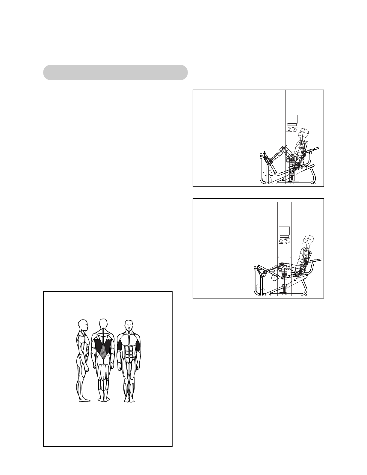
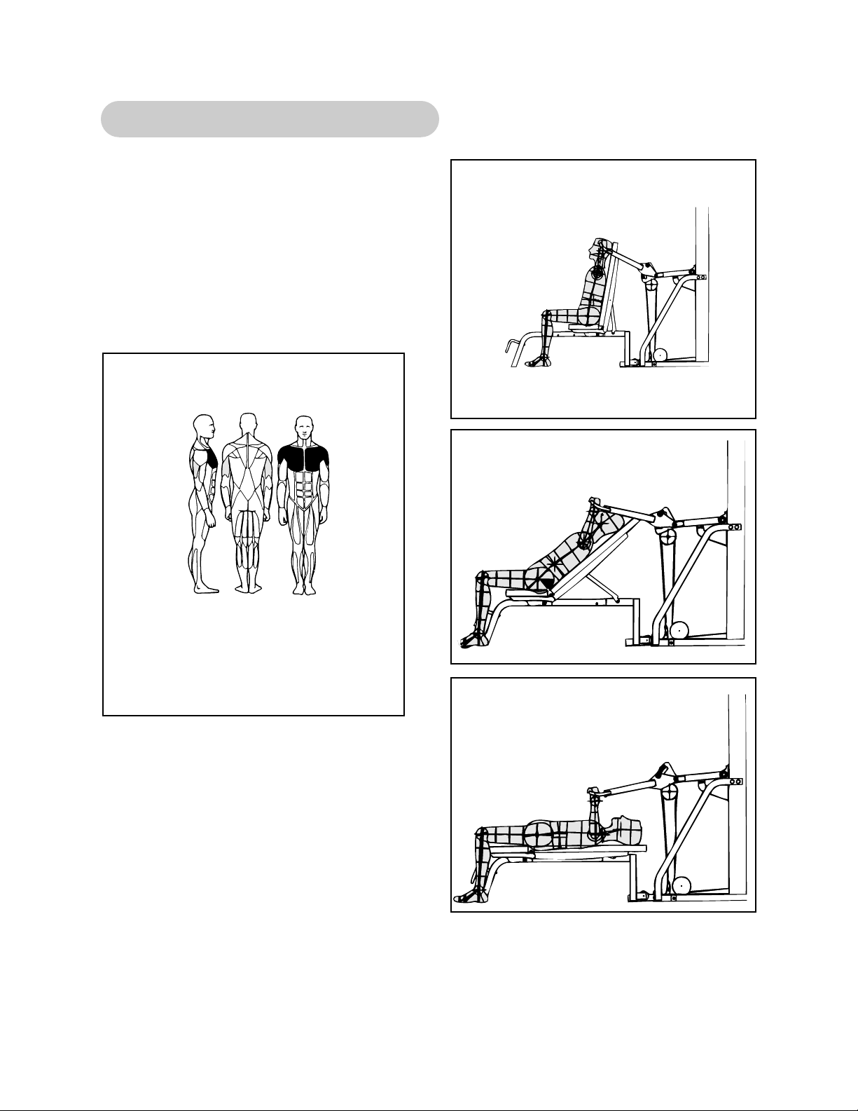
5652/5322 - Modular Seated Leg Press
MUSCLES TRAINED
Primary - Pectoralis Major
Secondary - Anterior Deltoid, Triceps
(Basic Press) and Biceps
(Advanced Press)
Start Position
Stop Position
Page 26

Page 2-2
Cybex Modular Owner’s Manual
This page intentionally left blank
Page 27
Page 2-3
Cybex Modular Owner’s Manual
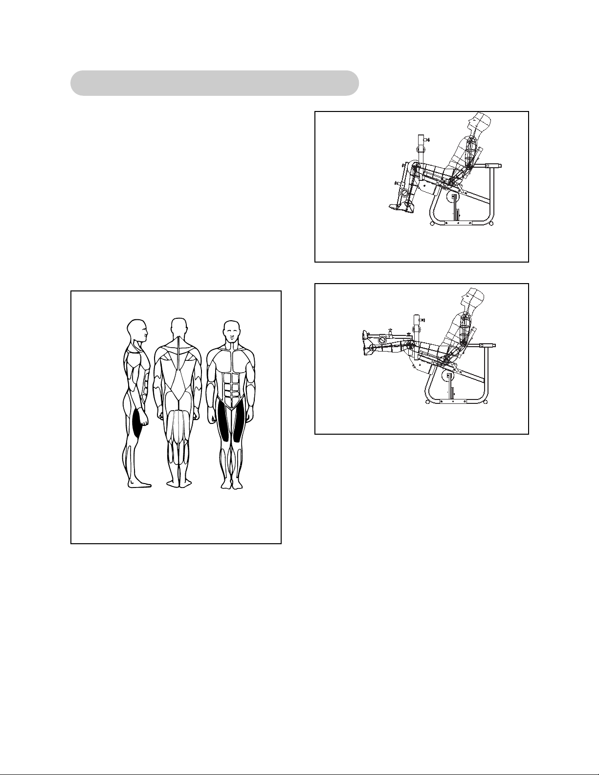
5653/5307 - Modular Leg Extension/Leg Curl
1. Select appropriate resistance.
2. Adjust back pad so that center of knees align
with machine’s axis of rotation.
3. Pull detent pin on input arm, lowering arm
into one of the two start positions.
4. Pull detent pin and adjust height of lower leg
pads to a height comfortable above ankles.
5. Lift/lower resistance with smooth, controlled
movements without resting.
MUSCLES TRAINED
Primary - Pectoralis Major
Secondary - Anterior Deltoid, Triceps
(Basic Press) and Biceps
(Advanced Press)
Start Position
Stop Position
Start Position
Stop Position
Page 28

Page 2-4
Cybex Modular Owner’s Manual
This page intentionally left blank
Page 29
Page 2-5
Cybex Modular Owner’s Manual
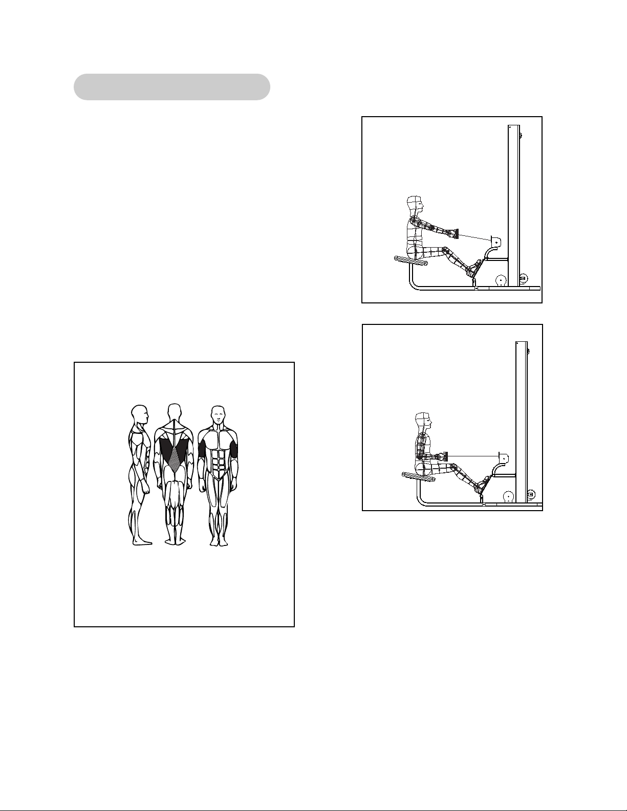
5651/5302 - Modular Low Row
1. Select appropriate resistance.
2. Grasp handle and position feet securely on
foot plate.
3. Position yourself comfortably on seat and
maintain a slight bend in the knees.
4. Throughout the exercise keep back straight
and upright.
5. Lift/lower resistance with smooth, controlled
movements.
NOTE: For optimum performance and safety,
avoid excessive bending of spine
during exercise.
MUSCLES TRAINED
Primary - Biceps and Latissimus Dorsi
Secondary - Erector Spinae
Start Position
Stop Position
Page 30

Page 2-6
Cybex Modular Owner’s Manual
This page intentionally left blank
Page 31

Page 2-7
Cybex Modular Owner’s Manual
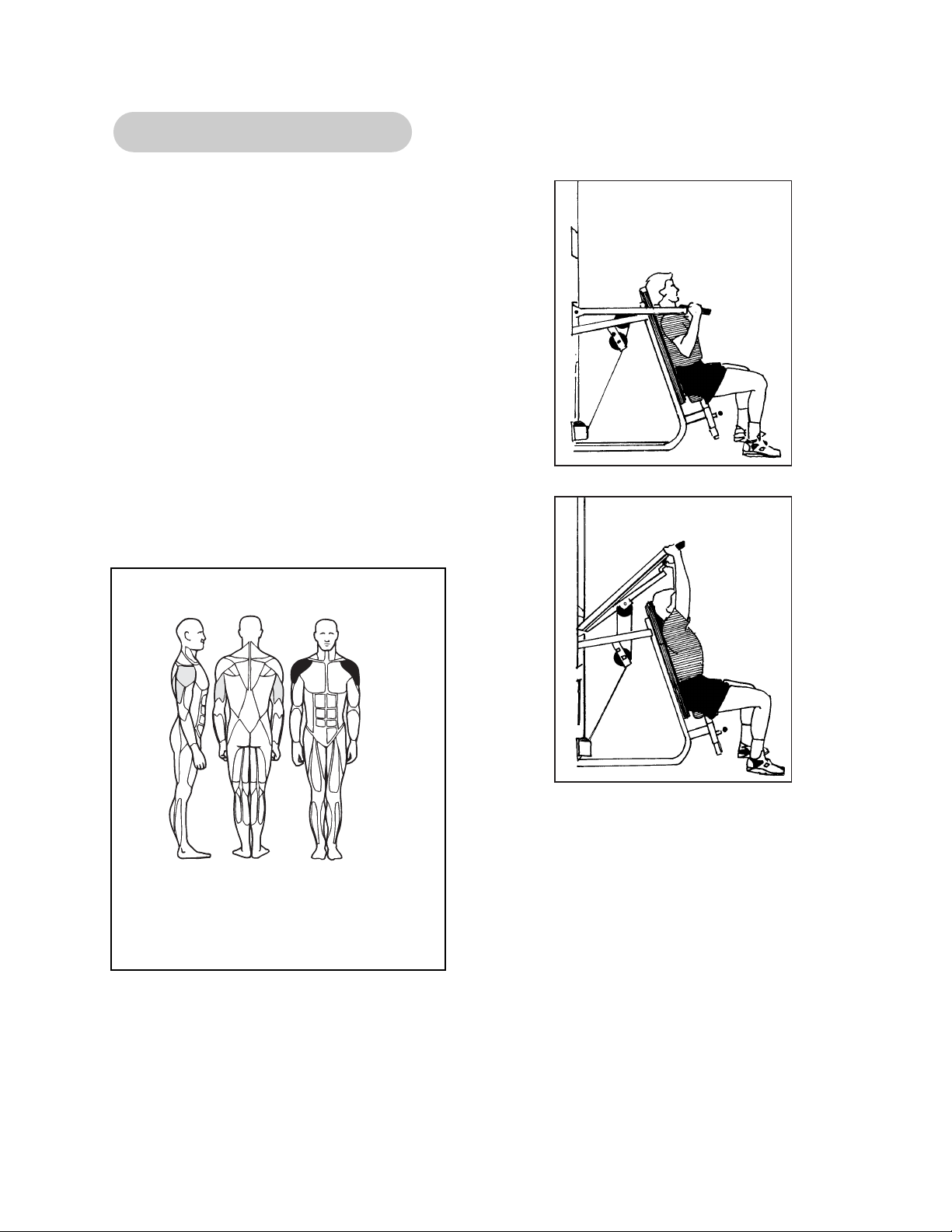
5601 - Modular Lat Pulldown
1. Adjust thigh pads to allow access and stabilization while
exercising.
2. Slect appropriate resistance.
3. Grasp bar and sit down, securing knees under thigh pads.
4. Lean back slightly at hips and maintain position throughout
movement.
5. With chest up and shoulders held back, pull bar down in front
to upper part of chest. Your elbows should move down to the
sides of your body.
6. Return to the start position and repeat.
7. Lift/lower resistance with smooth, controlled movements.
NOTE: Grasping the bar excessively wide or narrow, does not increase muscular
effectiveness. It only decreases your range of motion.
Read and understand all instructions and warnings prior to using this machine. See Chapter 1,
Safety in the Modular Owner’s Manual or consult with floor staff.
MUSCLES TRAINED
Primary - Latissimus Dorsi, Teres Major
Secondary - Biceps, Rhomboids and
Lower Trapezius
Page 32

Page 2-8
Cybex Modular Owner’s Manual
This page intentionally left blank
Page 33
Page 2-9
Cybex Modular Owner’s Manual
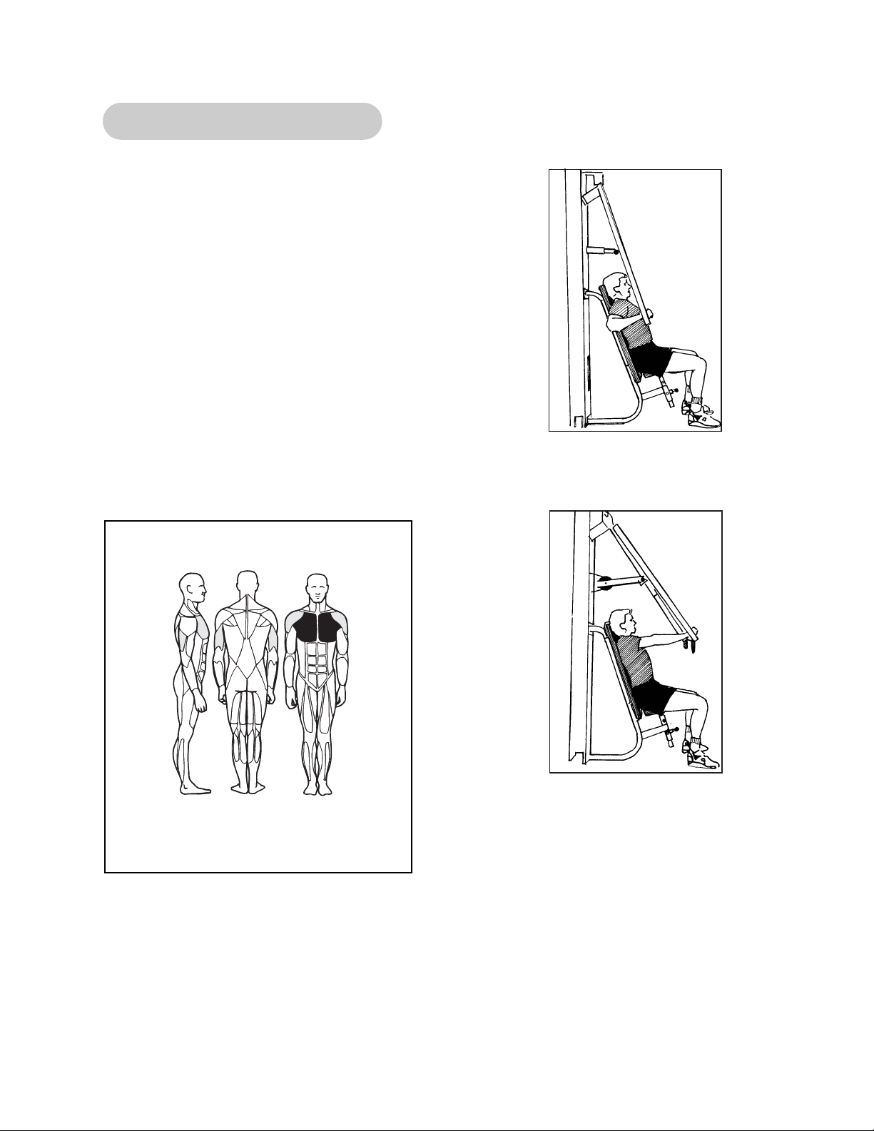
5640 - Modular Chest Press
1. Adjust seat height so that handles are at
mid-chest.
2. Adjust handle position so that when grasped,
upper arms are straight to side.
3. Select appropriate resistance.
4. Grasp handles.
5. Position elbows out to side, level with handles.
6. With chest up and shoulders held back, press
handles forward with a smooth, controlled
movement.
7. Lift/lower resistance with smooth, controlled
movements.
MUSCLES TRAINED
Primary - Pectoralis Major
Secondary - Anterior Deltoid and
Triceps
Start Position
Stop Position
Page 34

Page 2-10
Cybex Modular Owner’s Manual
This page intentionally left blank
Page 35
Page 2-11
Cybex Modular Owner’s Manual
5647/5306 - Modular Pressing Station
1. Select appropriate resistance.
2. Adjust the bench back pad angle (flat, 30, 40,
60, 80).
3. Adjust pressing arm to desired position.
4. Lift/lower resistance with smooth, controlled
movements.
MUSCLES TRAINED
Primary - Pectoralis Major, Anterior
Deltoids (depending upon bench
angle)
Secondary - Triceps
Start Position
Start Position
Stop Position
Page 36

Page 2-12
Cybex Modular Owner’s Manual
This page intentionally left blank
Page 37
Page 2-13
Cybex Modular Owner’s Manual
5639 - Modular Shoulder Press
1. Adjust seat height so that handles are level
with shoulders.
NOTE: Range of motion may be reduced by
selecting a lower seat position.
2. Select appropriate resistance.
3. Grasp either set of handles.
TIP: The parallel handles will help reduce
shoulder impingement and may be more
comfortable for some users.
4. Press straight up with a smooth, controlled
movement.
5. Return to the start position and repeat.
MUSCLES TRAINED
Primary - Anterior Deltoids
Secondary - Middle Deltoids and
Triceps
Start Position
Stop Position
Page 38

Page 2-14
Cybex Modular Owner’s Manual
This page intentionally left blank
Page 39
Page 2-15
Cybex Modular Owner’s Manual
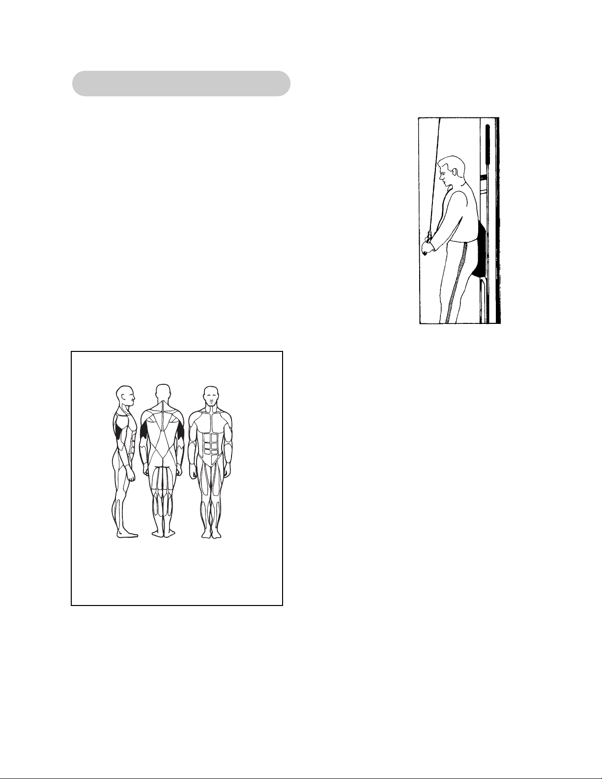
5603 - Modular Tricep Pressdown
1. Select appropriate resistance.
2. Attach the desired handle to the clip.
3. Position yourself with your hips and back firmly against
back pad.
4. While leaning forward slightly, extend your arms downward
maintaining your elbows in a stationary position.
5. Return to the start position and repeat.
6. Lift/lower with smooth, controlled movements.
NOTE: The appropriate grip position allows you to keep
your chest up and shoulders held back while
extending your arms.
MUSCLES TRAINED
Primary - Triceps
Page 40

Page 2-16
Cybex Modular Owner’s Manual
This page intentionally left blank
Page 41
Page 2-17
Cybex Modular Owner’s Manual
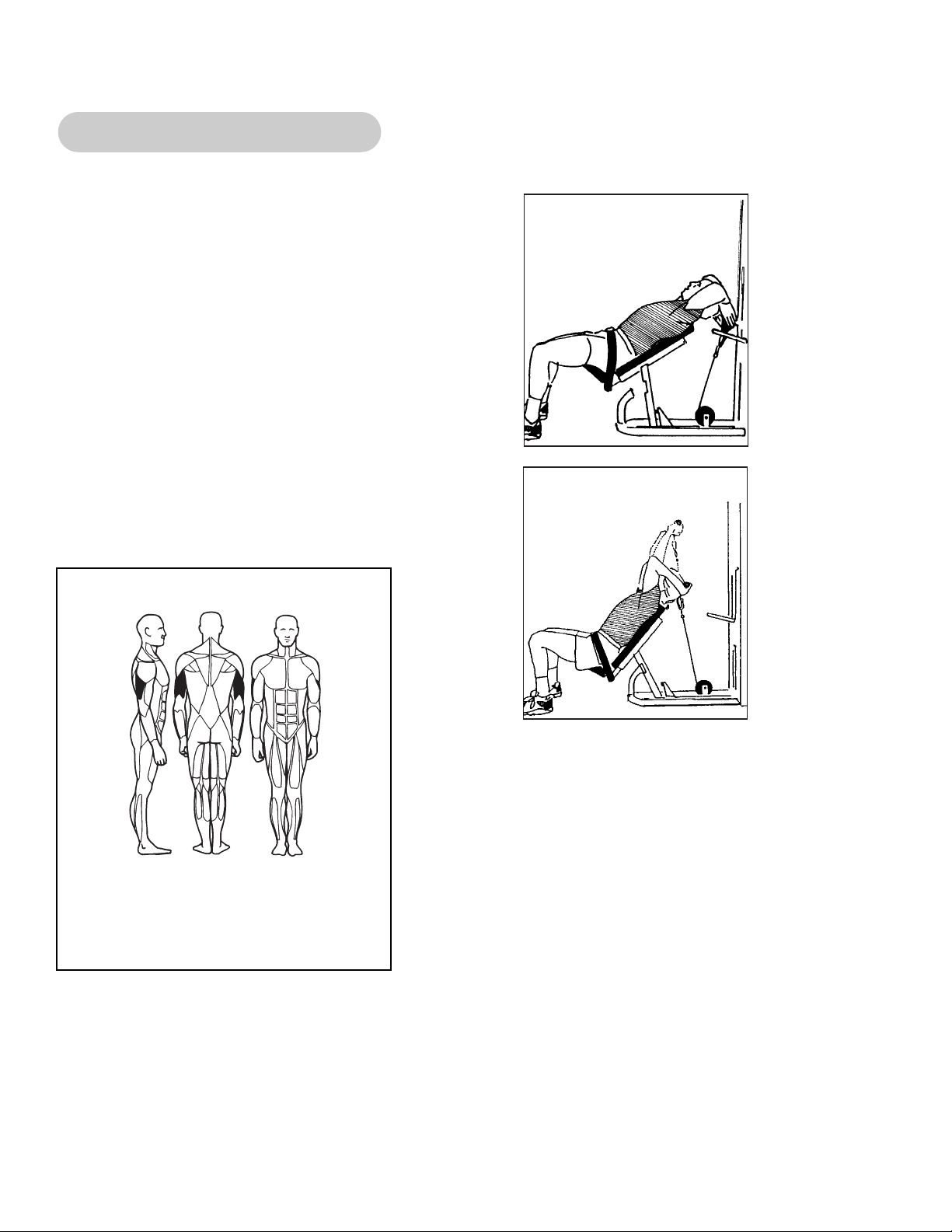
5641 - Modular Tricep Extension
1. Select appropriate resistance.
2. Position yourself in chair, attaching seat belt
to assist in stabilization.
3. Pivot chair backwards to grasp handle. Lower
seat back down to begin exercise.
4. Maintain elbows in a stationary position while
extending arms overhead.
5. Lift/lower resistance with smooth, controlled
movements.
6. When exercise is complete, lean chair
backwards to replace handle. Ensure
handle has been securely replaced before
letting go.
MUSCLES TRAINED
Primary - Triceps
Start Position
Stop Position
Page 42

Page 2-18
Cybex Modular Owner’s Manual
This page intentionally left blank
Page 43

1. Adjust seat height to allow your upper arms to
rest on pad.
2. Select appropriate resistance.
3. Grasp bar, position arms parallel on pad.
4. Lower your shoulders, pressing your arms
firmly into the pad, elevating your elbows
slightly.
5. Curl arms as far as possible, maintaining your
elbow position.
6. Return to the start position and repeat.
7. Lift/lower resistance with smooth, controlled
movements.
Page 2-19
Cybex Modular Owner’s Manual
5644 - Modular Arm Curl
MUSCLES TRAINED
Primary - Biceps
Secondary - Brachioradialis and
Bracialis
Start Position
Stop Position
Page 44

Page 2-20
Cybex Modular Owner’s Manual
This page intentionally left blank
Page 45

Page 2-21
Cybex Modular Owner’s Manual
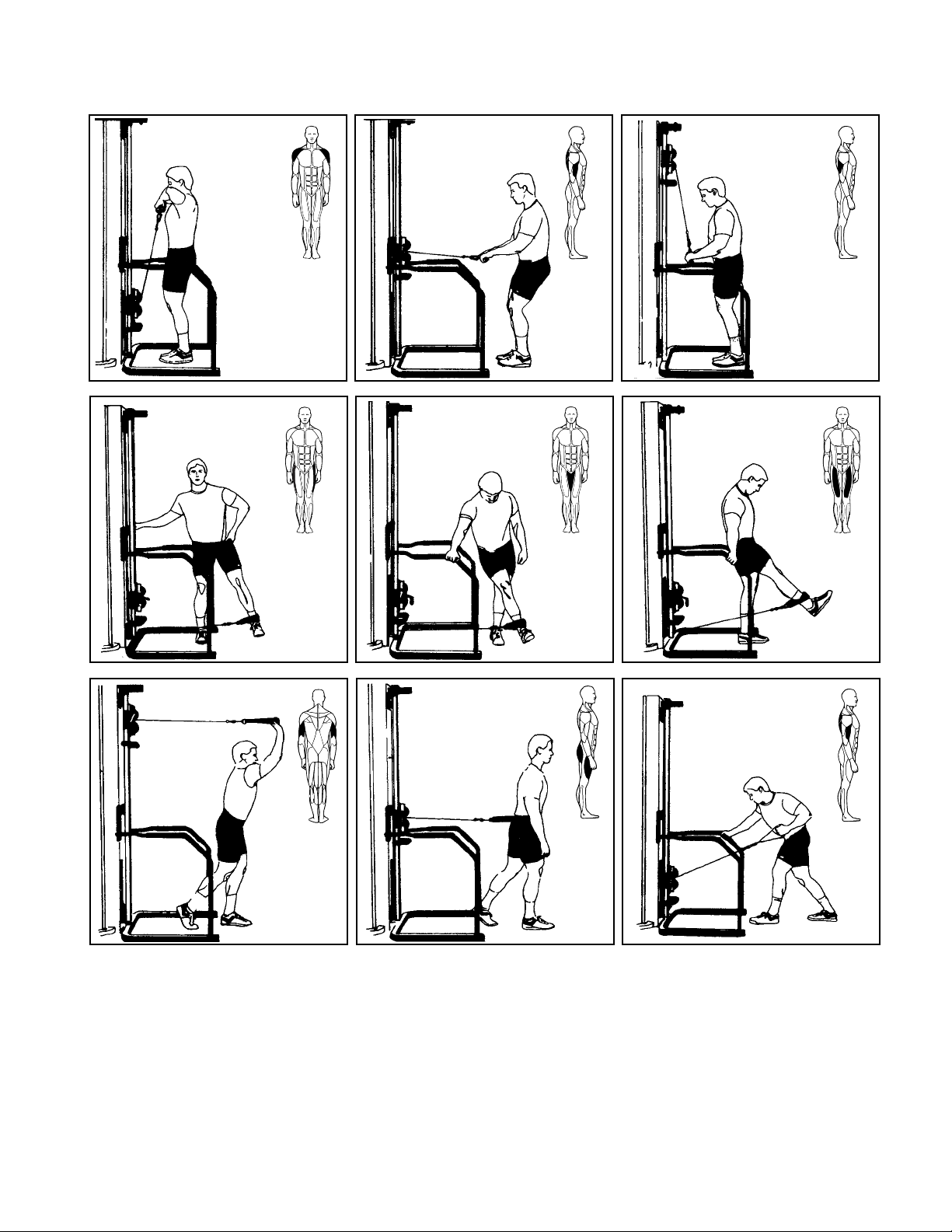
5648/5649/5650/5311 - Modular Cable Crossover
The Cable Crossover is a very versatile machine. With the use of various handles, virtually
every body part can be trained.
1. Select appropriate resistance.
2. Adjust pulley height by grasping handle, pulling detent pin, sliding mechanism to desired
height. Ensure that pin is locked into place before releasing handle.
3. Grasp handle securely and lift/lower resistance with smooth, controlled movements.
NOTE: Exercises may be performed in either linear or diagonal patterns.
Pectoralis Major
Anterior Deltoid
Rotator Cuff Pectoralis Major
Anterior Deltoid
Pectoralis Major
Anterior Deltoid
Pectoralis Major
Page 46

Page 2-22
Cybex Modular Owner’s Manual
Latissimus Dorsi
Teres Major
Triceps
Side Deltoid
Triceps
Latissimus Dorsi
Biceps
Biceps
Glutes
Hamstrings
Hip AbductorsHip Adductors
Page 47

Page 2-23
Cybex Modular Owner’s Manual
5605.5633/5315/5316 - Modular Cable Column
The Cable Column is a very versatile machine. With the use of various handles, virtually every
body part can be trained.
1. Select appropriate resistance.
2. Adjust pulley height by grasping handle, unlocking twist knowb, sliding mechanism to the
desired height. Ensure that the twist knob has been locked before releasing handle.
3. Grasp handle securely and lift/lower resistance with smooth, controlled movements.
NOTE: Exercises may be performed in either linear or diagonal patterns.
Pectoralis Major
Anterior Deltoid
Side Deltoid
Pectoralis Major Pectoralis Major
Rotator Cuff
Latissimus Dorsi
Teres Major
Page 48
Page 2-24
Cybex Modular Owner’s Manual
Deltoids
Hip Abductors
Latissimus Dorsi
Biceps
Hip Adductors
Triceps
Hip Flexors
Quadriceps
Triceps
Quadriceps
Glutes
Latissimus Dorsi
Biceps
Page 49
Page 2-25
Cybex Modular Owner’s Manual
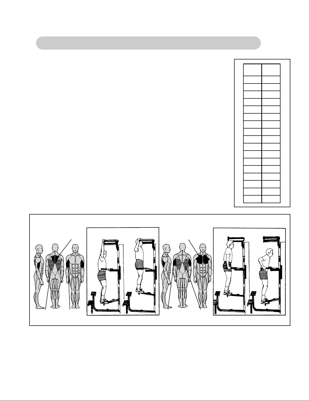
5611 Modular Assisted Chin-Up/Dip and 5345 - Single Station Dip/Chin
1. Select assisted (foot support down) or unassisted (foot support
pivots up against tower) dip or chin exercise.
2. Select appropriate resistance.
3. Select wide or narrow grip position.
4. Grasp exercise handles securely.
5. For assisted dip or chin exercise, place feet firmly on the foot support.
6. Lift/lower body with smooth, controlled movements.
NOTE: Exit machine from top step only! Do not exit machine from ground level.
Plate
No.
18
19
20
Assist
(Pounds)
164
225
286
347
408
469
5210
5811
6412
7013
7614
8215
8816
9417
100
106
112
Muscles Trained
Rhomboids
Latissimus Dorsi Biceps
Start
Finish
Muscles Trained
Pectoralis Group
Triceps
Latissimus Dorsi
Start
Finish
Page 50

Page 2-26
Cybex Modular Owner’s Manual
This page intentionally left blank
Page 51

Cybex Modular Owner’s Manual
Page 3-1
Contacting Service
3 - Customer Service
Hours of phone service are Monday through Friday from 8:00 a.m. to 6:00 p.m. Eastern
Standard Time.
For Cybex customers living in the USA, contact Cybex Customer Service at 800-766-3211.
Your options at this number include:
• Press 63 to place a parts order or to check parts order status.
• Press 64 to speak to a technical support representative regarding troubleshooting or to
schedule a field service call.
• Press 65 to check status of a repair order only and you have your RRM number.
• Press 66 to check status of a dispatched field service call and you have your inquiry
number.
• Press 67 for service of a medical or isokinetic product.
• Press 0 to go to the Cybex operator.
For Cybex customers living outside the USA, contact Cybex Customer Service at 508-533-
4300 or fax 508-533-5183.
Order parts and find information on the web at www.eCybex.com or by e-mail at
techhelp@cybexintl.com.
Ordering Parts
Visit eCybex.com to shop for parts online or fax your order to 508-533-5183.
To speak with a customer service representative, call 800-766-3211 (for customers living within the USA) or 508-533-4300 (for customers outside the USA). You may also contact us
through email at techhelp@cybexintl.com
Having the following information ready when calling will assist our Cybex representatives in
serving you:
• Unit Serial Number
• Product Name
The unit serial number and product name can be found on the serial number decal. See
Chapter 6 for exact location of serial number decal.
• Part Description
• Part Number
Part descriptions and part numbers are located in Chapter 6 of this manual.
Page 52

Cybex Modular Owner’s Manual
Page 3-2
The Return Material Authorization (RMA) system outlines the procedures to follow when
returning material for placement, repair, or credit. The system assures that returned materials
are properly handled and analyzed. Follow the following procedures carefully.
Contact your authorized Cybex dealer on all warranty-related matters. Your local Cybex
dealer will request a RMA from Cybex, if applicable. Under no circumstances will defective
parts or equipment be accepted by Cybex without proper RMA and an Automated Return
Service (ARS) label.
1. Call the Customer Service Hotline listed above for the return of any time that is
defective.
2. Provide the technician with a detailed description of the problem you are having or
the defect in the item you wish to return.
3. Provide the model and serial number of your Eagle equipment
4. At Cybex’s discretion, the technician may request that you return the problem
part(s) to Cybex for evaluation and repair or replacement. The technical will assign
you a RMA number and will send you an ARS label. The ARS label and the RMA
numbers must be clearly displayed on the outside of the package that contains the
item(s) to be returned. Include the description of the problem, the serial number of
the Eagle equipment and the name and address of the owner in the package along
with the part(s).
5. Forward the package through UPS to Cybex.
Attn: Customer Service Department
Cybex International, inc.,
10 Trotter Drive
Medway, MA 02053
NOTE: Merchandise returned without an RMA number on the outside of the package or
shipments sent C.O.D. will not be accepted by the Cybex receiving department.
Return Material Authorization (RMA)
• Shipping Address
• Contact Name
In addition to your shipping address and contact name, your account number
is helpful but not required.
Page 53

Cybex Modular Owner’s Manual
Page 3-3
Materials damaged in shipment should not be returned for credit. Shipping damages are the
responsibility of the carrier (UPS, Federal Express, trucking companies, etc.)
Apparent Damage - Upon receipt of your shipment, check all items carefully. Any damage
seen with a visual check must be noted on the freight bill and signed by the carriers agent.
Failure to do so will result in the carriers refusal to honor your damage claim. The carrier will
provide you with the required forms for filing such claims.
Concealed Damage - Damage not seen with a visual check upon receipt of a shipment but
notices later must be reported to the carrier as soon as possible. Upon discovery of the damage, a written or phone request to the carrier asking them to perform an inspection of the
materials must be made within ten days of the delivery date. Keep all shipping containers and
packing materials as they will be needed in the inspection process. The carrier will provide
you with and inspection report and the necessary forms for filing a concealed damage claim.
Concealed damage claim is the carriers responsibility.
Damaged Parts
Page 54

Cybex Modular Owner’s Manual
Page 3-4
This page intentionally left blank
Page 55
4 - Assembly
Page 4-1
Cybex Modular Owner’s Manual
TOOLS REQUIRED
• 5/16” Allen wrench
• Soft hammer
• Medium weight automotive engine oil
NOTE: Refer to the appropriate Assembly & Parts Instruction sheet (weight stack diagrams)
when performing the procedure listed below.
1. Remove the two socket head cap screws securing the guide rods.
2. Carefully lean guide rods away from column.
3. Remove guide rod collets and plastic caps.
4. Wipe guide rods clean over entire length. Lubricate with light coating of medium weight
automotive engine oil.
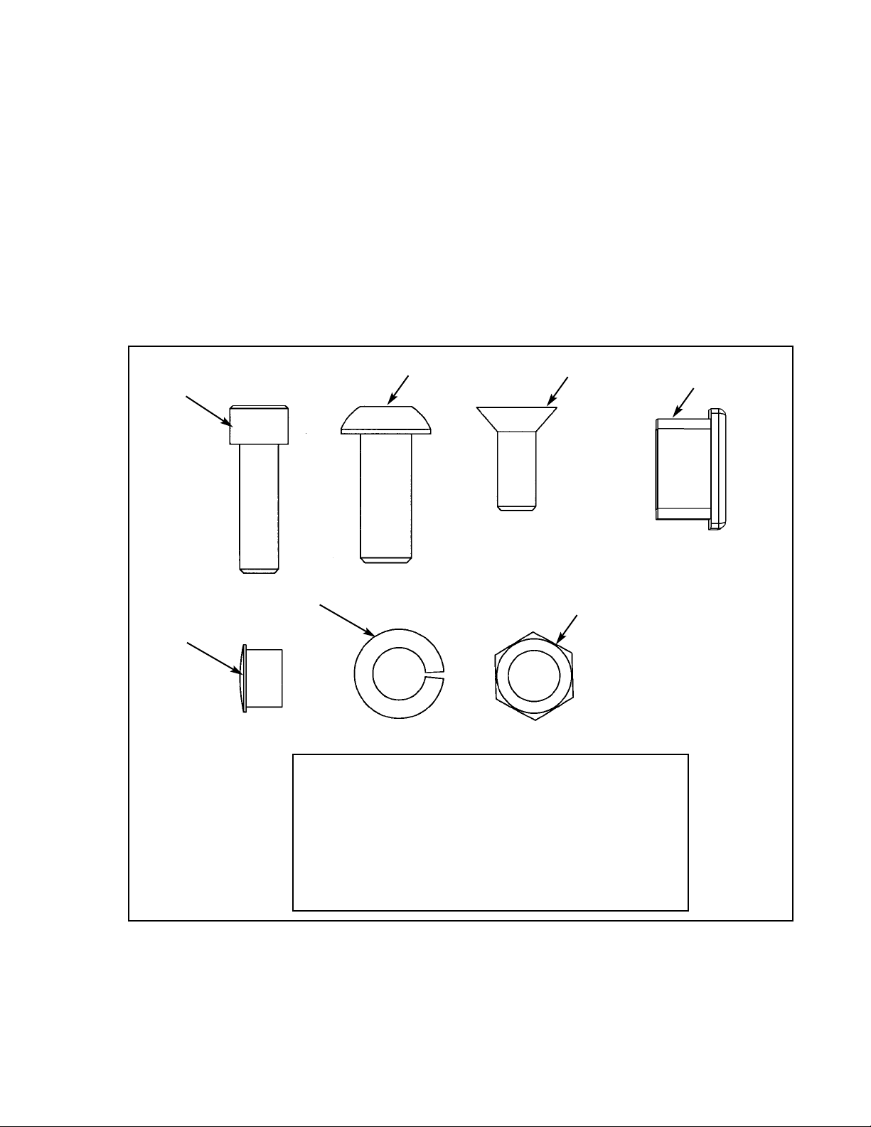
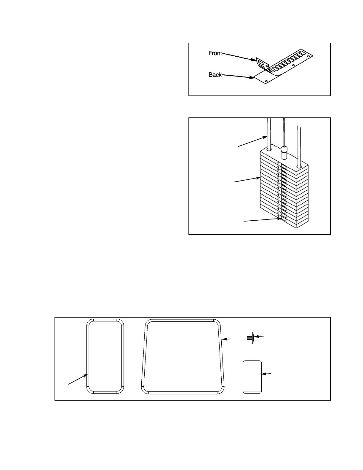
5. Install each weight plate one at a time, starting with the last plate (going from highest
numerical value to lowest). NOTE: For 15 and 25 weight plate stacks, the first plate installed
has no number. NOTE: When installing weight plates, position plates so wide edges of bushings
face upward and narrow edges of bushings face downward. See example below..
6. Install top weight.
7. Replace plastic caps and guide rod collets on guide rods.
8. Return guide rods to full upright position.
Weight Stack Installation
NOTE: Refer to Chapter 6 (Assembly and Service) for further assembly information.
CORRECT
NARROW bushing
edge
WIDE bushing
edge faces upward
NOTE: The narrow
bushing edge must
face downward.
WRONG
Page 56

Cybex Modular Owner’s Manual
Page 4-2
9. Insert both socket head cap screws that were removed in step 1 and tighten securely.
10. Insert cable end into top weight and align cable fitting opening with opening in top
weight for proper cable tension. NOTE: See Cable Adjustment and Installation Section.
11. Using a hammer drive roll pin through top plate connector and cable fitting. Assure pin is
flush with top plate collar.
12. Insert selector pin into each plate to assure proper alignment. See Cable Adjustment and
Installation section if selector pin does not fit smoothly, or if cable appears to have
excessive slack.
13. Place half weight on weight peg (if applicable).
Page 57
Cybex Modular Owner’s Manual
Page 4-3
MODULAR HANDLE RACK
5631 ASSEMBLY & PARTS
A. Handle Rack....................... 5631
DESCRIPTION PART NO.
A
Page 58

Cybex Modular Owner’s Manual
ITEM QTY PART NO. DESCRIPTION
1 1 01930 Handle Rack
2 4 PU060205 Rubber Bumper .88" T
3 2 JC780417 BHSCS .50-13 x 1.00
4 2 HN784000 Hex Nut .50-13
5 2 JS388300 Lockwasher .50
6 1 01937 Mounting Plate
5631 - Handle Rack
TOOLS REQUIRED
• 5/16" Allen wrench
• 3/4" Wrench
MOUNTING HANDLE RACK ON MODULAR UNITS
1. Install mounting plate (item 6) between towers with BHSCS (item 3),
hex nut (item 4), and lockwasher (item 5).
2. Remove paper backing from one of the pieces of tape that is located on backside of Handle Rack
(item 1). Place a rubber bumper (item 2) on the tape. Repeat this step until all four bumpers have
been placed on the Handle Rack.
3. Hang handle rack (item 1) over top edge of mounting plate (item 6).
NOTE: Be sure that the rubber bumpers rest against the perforated panel.
MOUNTING HANDLE RACK ON ANY UNITS WITH A BACK COVER
1. Remove paper backing from the four pieces of tape located on backside of Handle Rack (item 1).
2. Secure Handle Rack to back cover of unit.
MOUNTING HANDLE RACK TO A WALL
1. Remove paper backing from one of the pieces of tape that is located on backside of Handle Rack
(item 1). Place a rubber bumper (item 2) on the tape. Repeat this step until all four bumpers have
been placed on the Handle Rack.
2. Position handle rack against the wall (or mounting surface). Mark holes on the
wall through the four mounting holes in the Handle Rack.
3. Secure Handle Rack to the wall using the proper tools and hardware.
NOTE: This machine shipped with an Owner’s Manual. Additional copies can be obtained by contacting
your dealer or a Cybex Representative at 1-888-462-9239.
Page 59

Cybex Modular Owner’s Manual
Page 4-5
Page 60

Cybex Modular Owner’s Manual
Page 4-6
This page intentionally left blank
Page 61

Cybex Modular Owner’s Manual
Page 4-7
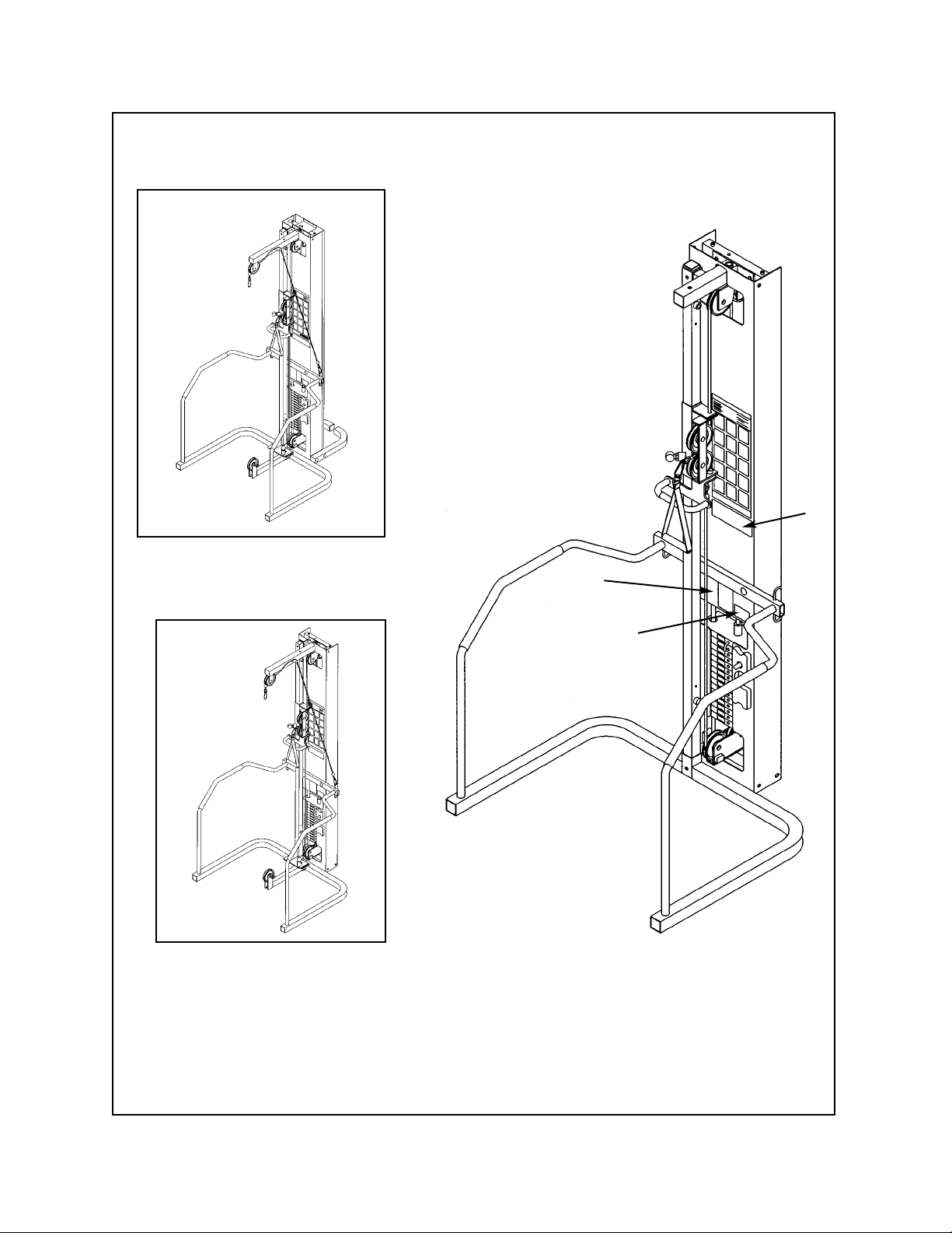
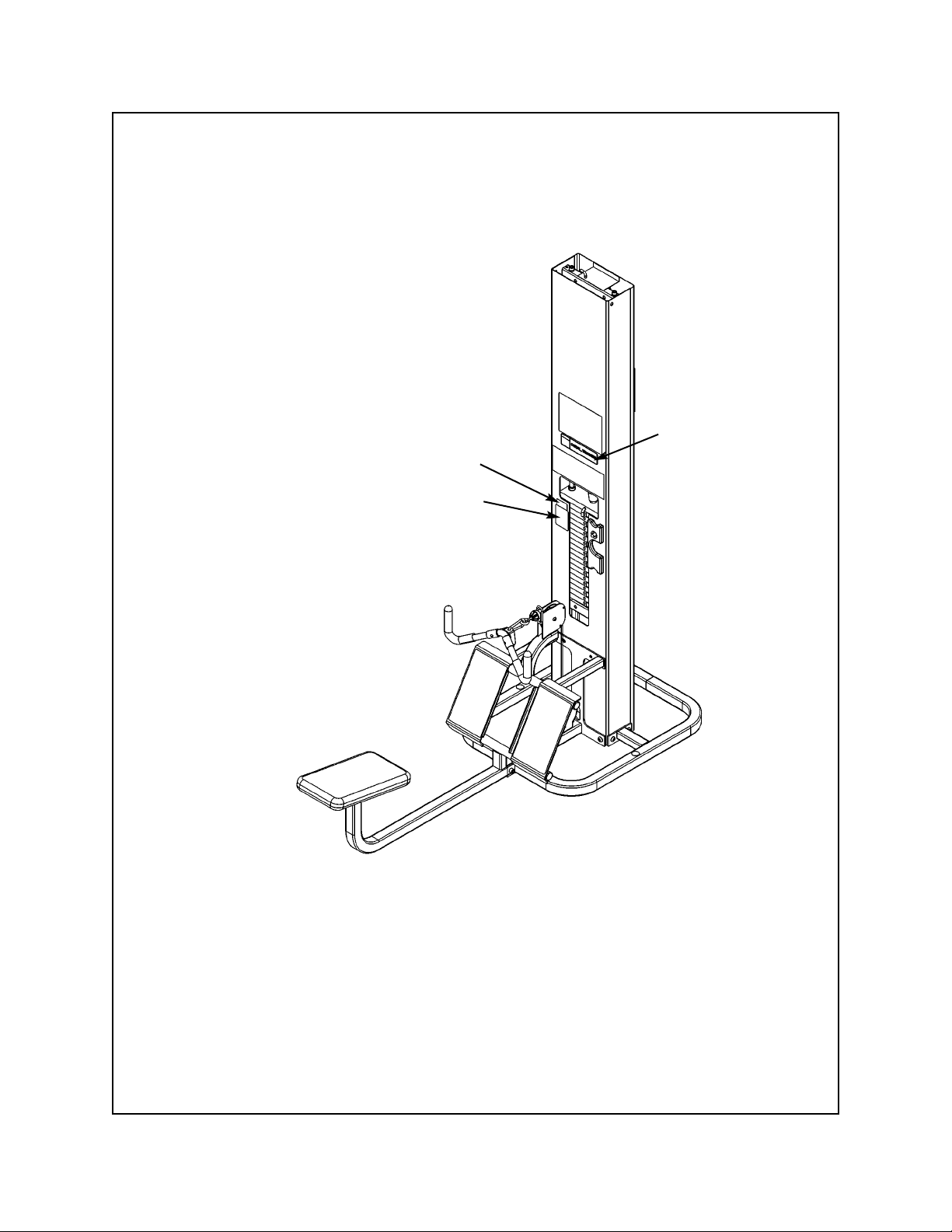
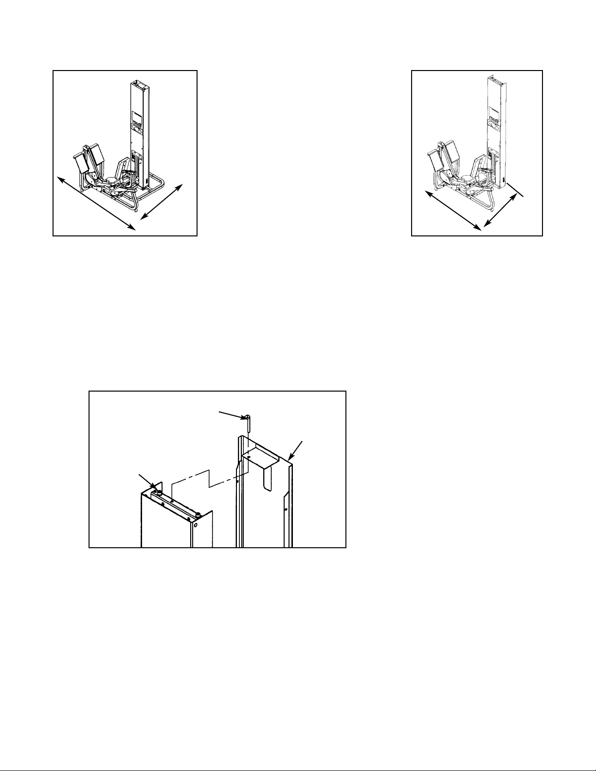
Modular Mover
5632
TOOLS REQUIRED
• 3/8” Allen wrench
• 3/8” Allen wrench
CAUTION!! When raising or lowering modular unit, keep hands and feet clear of columns, angle
supports and frame attachments.
1. Read and understand all instructions thoroughly before performing this procedure.
2. Verify you received the items shown in Figure 1.
Assembly Instructions
A. Handle Jack ...................... 01950
B. Jack Handle
C. Modular Mover .................. 01941
D. Lifting Bracket ................... 01951
E. Hex Nut.............................. HN784000
F. Split Lockwasher ............... JS388300
G. SHCS .500-13 x 2.75 ........ JC782832
DESCRIPTION PART NO.
3. Remove all perforated screens and set aside.
4. Remove all side stations (if applicable).
5. Install lifting bracket to the center of post using two
socket head cap screws. After tightening screws in
step 3, place hydraulic jack under lifting bracket
and raise modular unit approximately 1” off the
floor. See Figure 2.
Figure 1
Figure 2
A
B
C
D, E, F, G
Page 62

Cybex Modular Owner’s Manual
Page 4-8
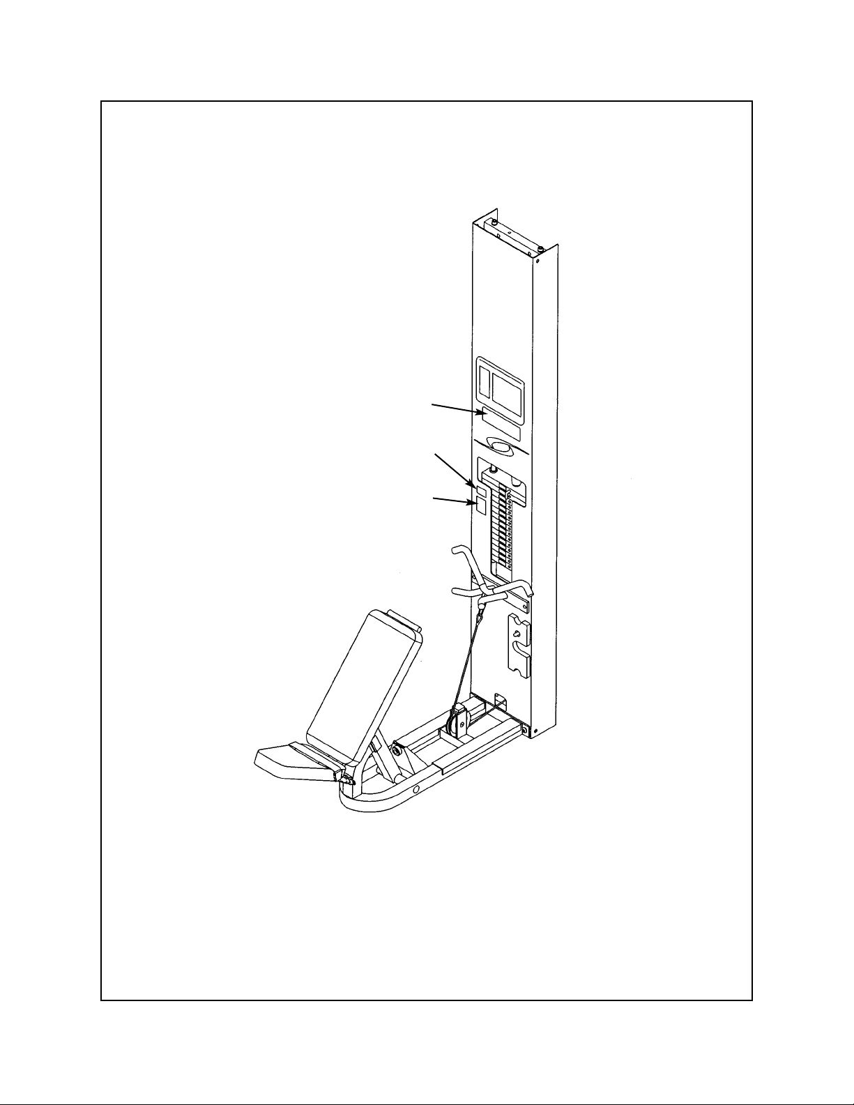
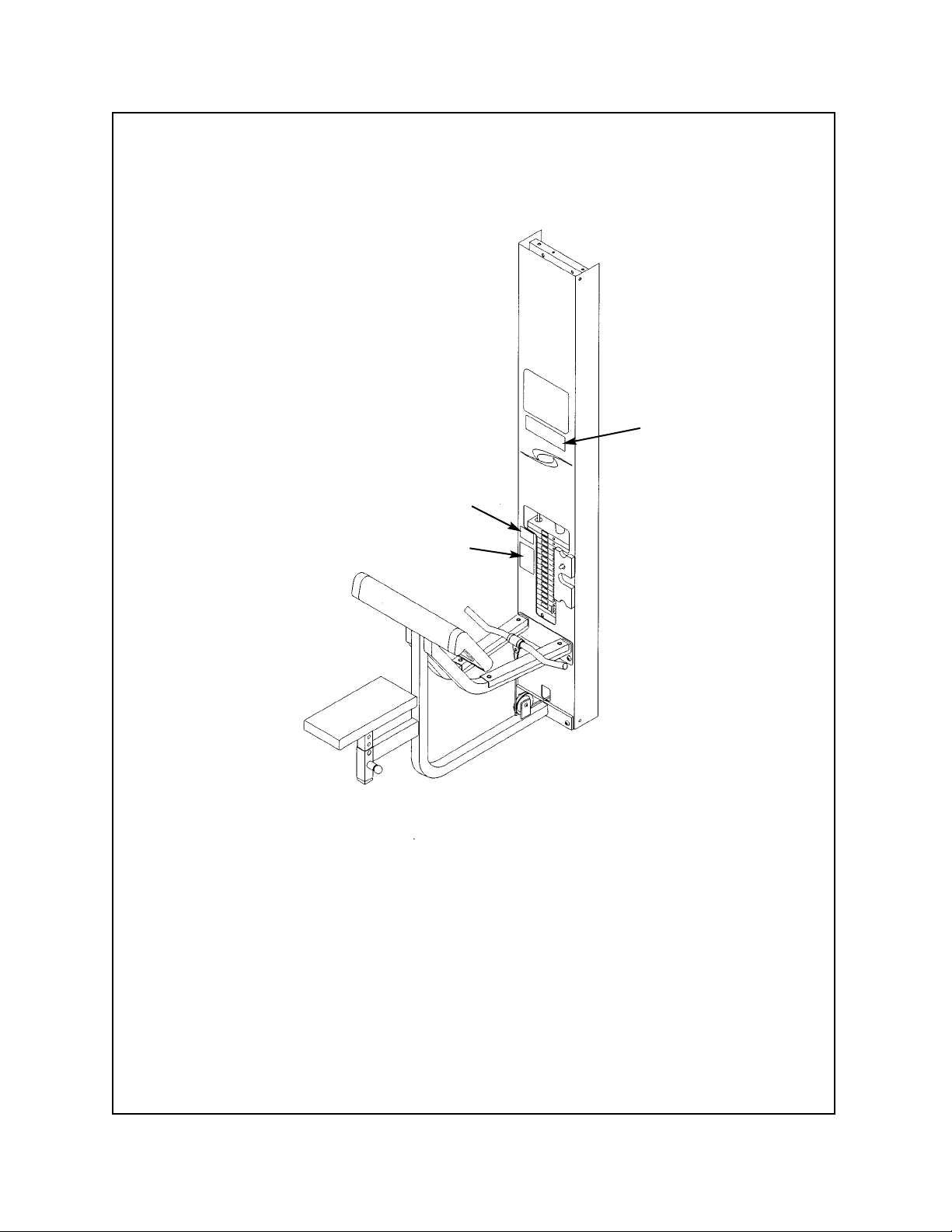
6. Install lift dolly and tighten in place using T-handle on dolly. See Figure 3.
7. Repeat step 4 for each remaining position around the modular unit. NOTE: If a leg Curl/Leg
Extension is next to an O.C. Cable Column, then do not install lift dolly in this position.
8. After lift dollies have been secured in place, the modular unit can be lowered and the hydraulic
jack can be removed.
9. Move modular unit to desired location. NOTE: When moving modular unit be sure to support any
pieces attached to the columns.
10. Position modular unit as desired. Install hydraulic jack and raise unit. Remove lift dollies and
lower modular unit.
11. Remove lifting bracket from center post.
12. Reattach any side stations.
13. Reattach perforated screens to the modular unit. Be sure screens are secured.
Figure 3
Page 63

Modular Seated Leg Press
5652 - Modular/Tandem configuration
5322 - Free Standing configuration
TOOLS REQUIRED
• 5/32” Allen wrench
• 7/32” Allen wrench
• 5/16” Allen wrench
• 3/8” Allen wrench
• 9/16” Socket/wrench
• 3/4” Socket/wrench
• Rubber mallet
• Step ladder
NOTE: A minimum of two people will be required to assemble the Leg Press configuration.
1. Read and understand all instructions thoroughly before assembling the Leg Press (see steps
A - C).
A. Locate the Modular Assembly & Service manual that you received with your order. If you did
not receive a manual contact Cybex Customer Service and ask for part number 55620.
B. If you are assembling the Leg Press station into a Tandem configuration, locate and review the
Tandem Center Post instructions contained with the Tandem configuration (this sheet is also
located in the Modular Assembly & Service manual). Skip step 1 in the Tandem Center Post
instructions.
C. If you are assembling the Leg Press station into a Modular configuration, locate and review
the Modular Center Post instructions contained with the Modular configuration. Skip step 1 in
the Modular Center Post instructions.
2. Verify you have received the appropriate configuration (see steps 2A - 2C, Figures 1 and 2).
• Hammer
• Utility knife
• Automotive engine oil
Assembly Instructions
Unpacking
A. If you ordered the Modular/Tandem
configuration (5262):
Shipping Package Part Number
• Leg Press Column 5562-9x
• Leg Press Package 5652-50
• Weight Package 4700S040
• Weight Package 4700S129
• Top Weight Package 4700-027
• Cushion Set 8630-010
B. If you ordered the Free Standing
configuration (5322):
Shipping Package Part Number
• Leg Press Column 5322-9x
• Leg Press Package 5652-50
• Leg Press Stabilizer 5302-51
• Weight Package 4700S040
• Weight Package 4700S129
• Top Weight Package 4700-027
• Cushion Set 8630-010
Cybex Modular Owner’s Manual
Page 4-9
Page 64
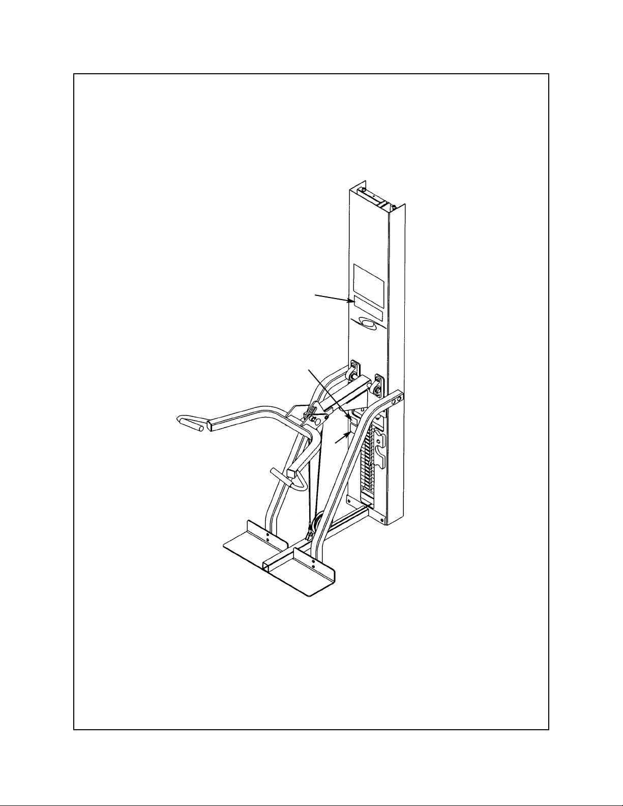
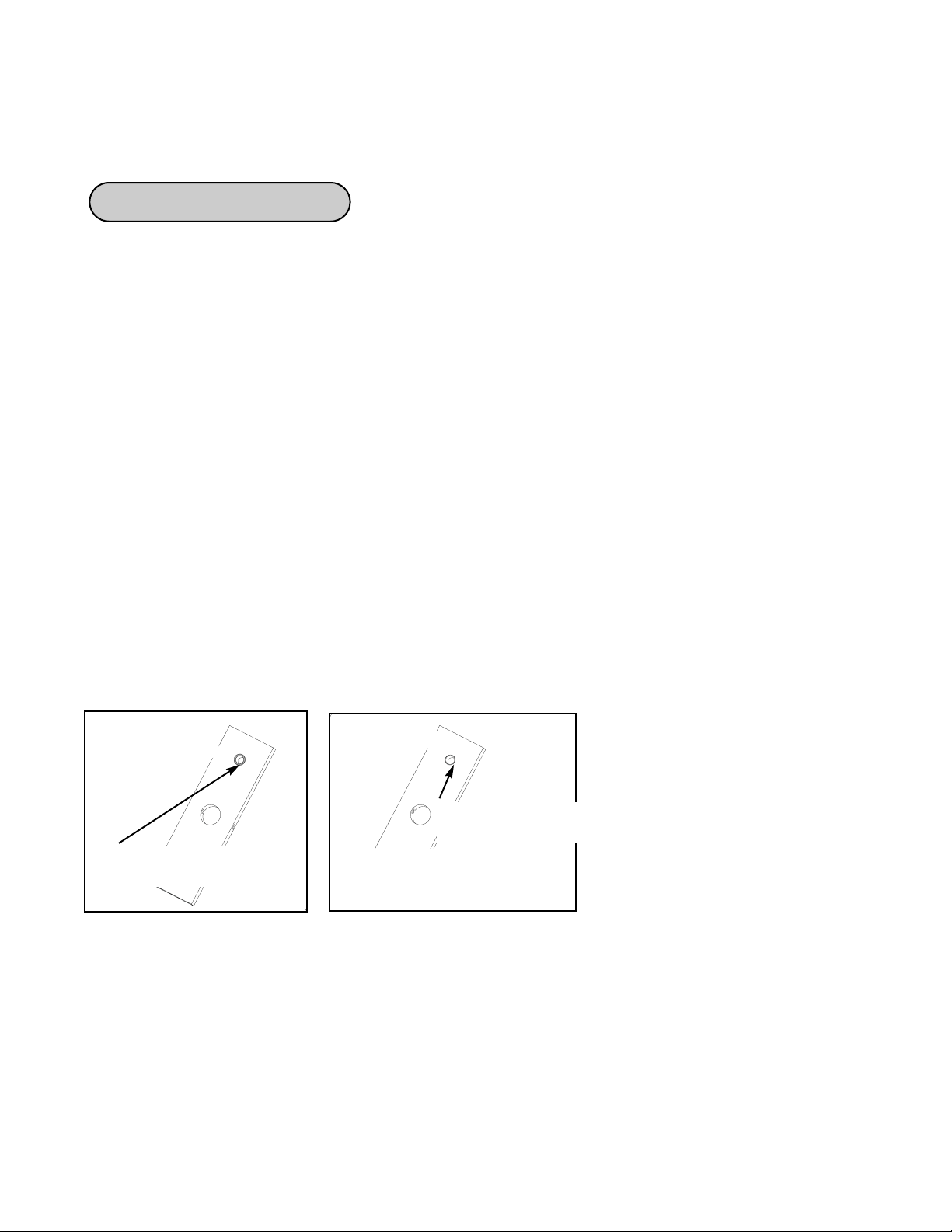
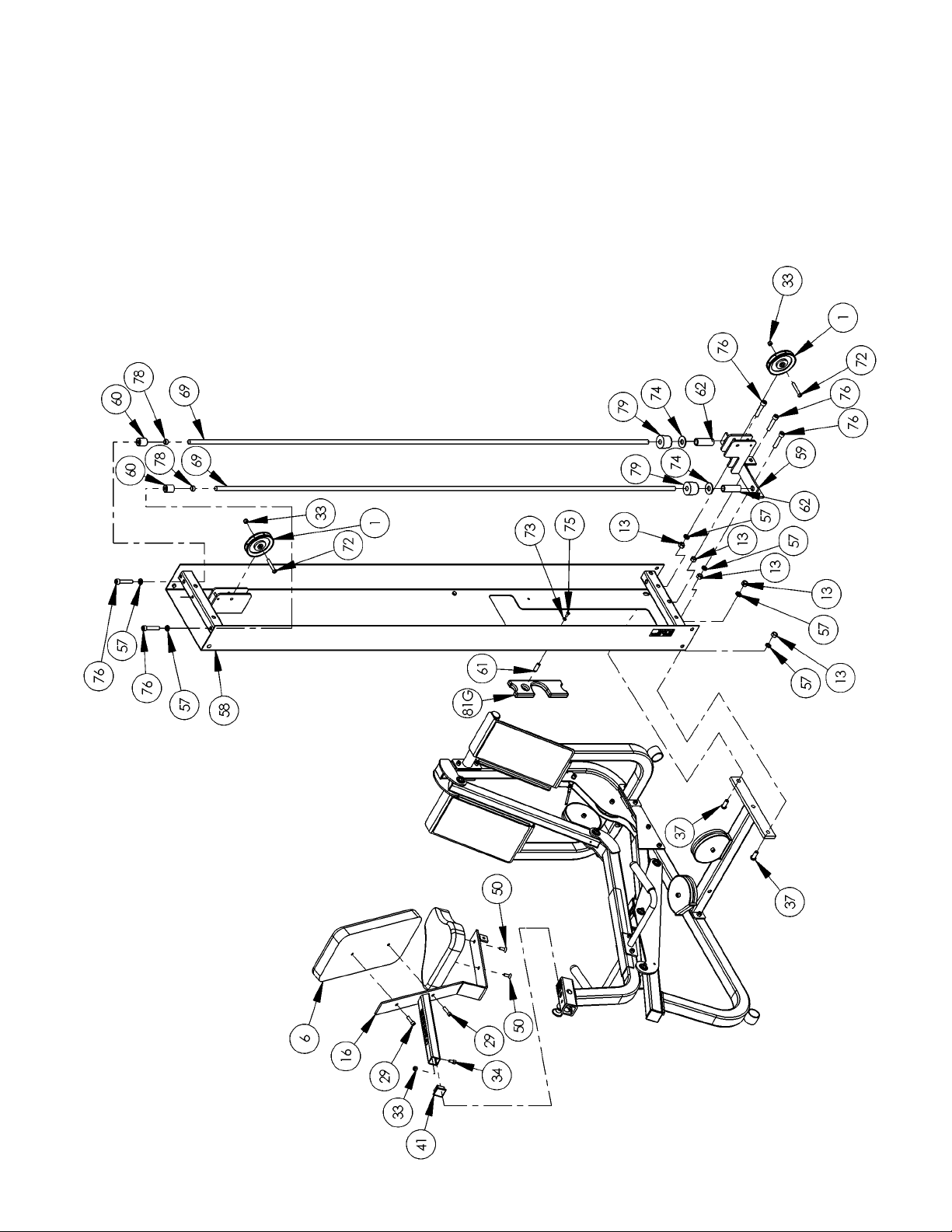
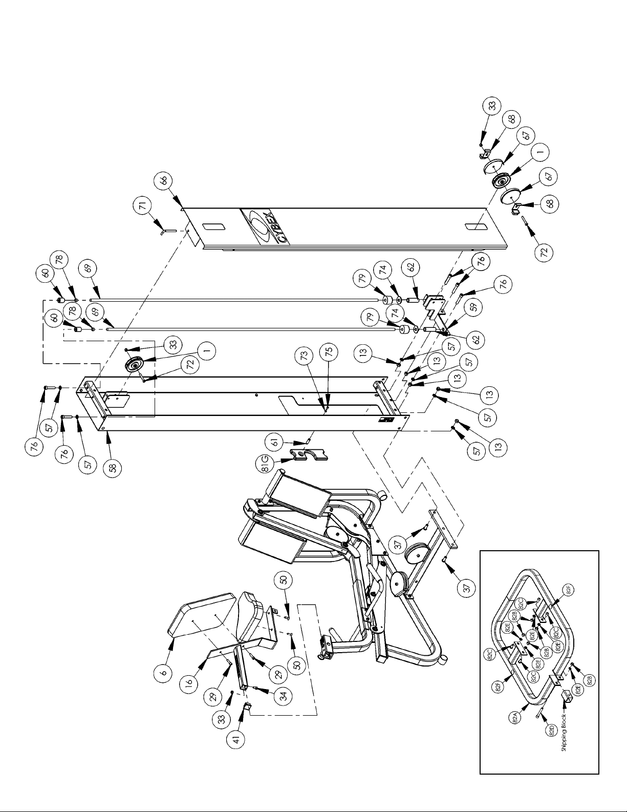
3. Unpack the carton containing the column (see steps 3A - 3I and Figures 3 - 8).
A. Locate and open the Leg Press Column carton.
B. The column should be laying so that the back side is facing upward.
C. For Free Standing units containing a back cover, remove the pin (#83) securing the back
cover (#66). Remove back cover by sliding it then lifting it upward. See Figure 3.
Figure 3
D. Remove the shipping supports securing the pulley mount and two hardware packs located
inside the column.
E. Verify contents of both hardware packs. See Figures 4 - 6.
NOTE: Figures 4 and 5 are for the Free Standing configuration.
Figures 5 and 6 are for the Tandem/Modular configuration.
83
Column
66
Figure 1
Figure 2
C. Carefully place shipping
packages near area of
installation.
D. For Free Standing configurations,
allow a minimum amount 92” x
89” for operating space. See
Figure 1.
E. For Modular/Tandem
configurations, allow a minimum
of 92” x 76” for operating space.
See Figure 2.
92”
89”
92”
76”
Cybex Modular Owner’s Manual
Page 4-10
Page 65
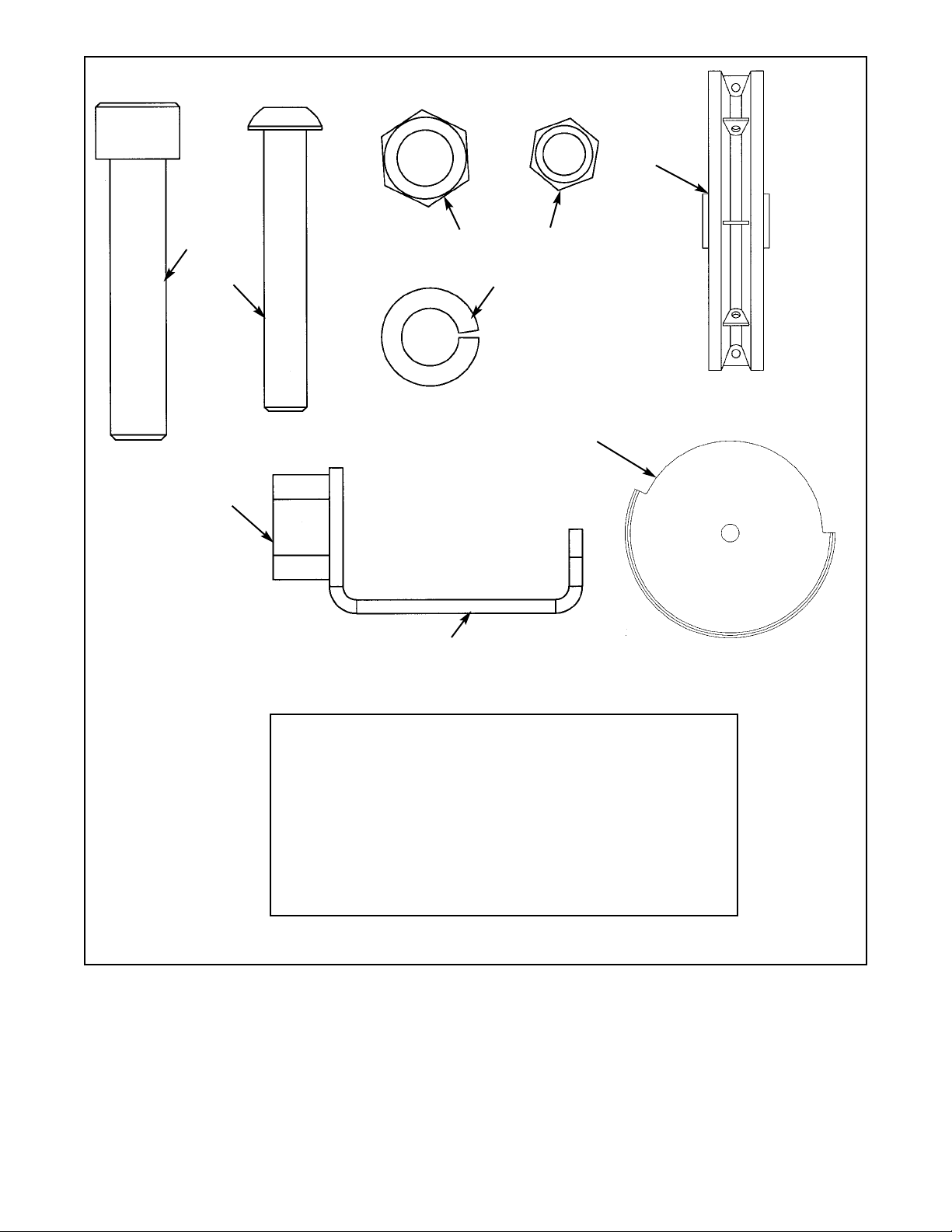
Figure 4
1 2 08014 Pulley Assembly
13 2 HN784000 Hex Nut .50-13
33 2 HN704901 Nylon Locknut .375-16
42 2 PU060201 Bumper
57 2 JS38800 Split Lockwasher .500
67 2 5301-310 Pulley Guard
68 2 5301-311 Stop
72 2 HC700430 BHSCS .375-16 x 2.50
76 3 JC782830 SHCS .50-13 x 2.50
ITEM QTY PART NO. DESCRIPTION
76
72
57
13
33
1
42
67
68
Cybex Modular Owner’s Manual
Page 4-11
Page 66
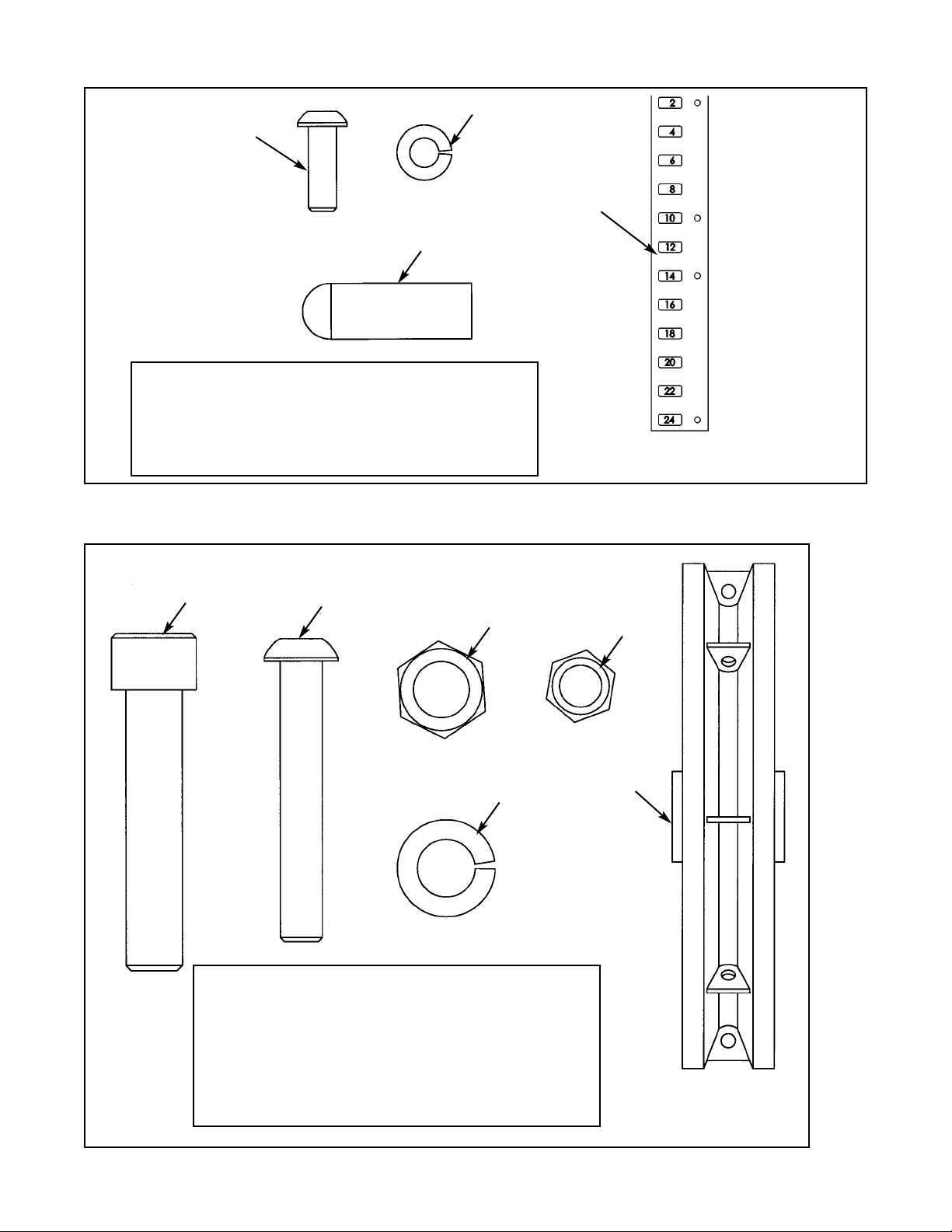
Figure 5
61 1 02106 Half Weight Peg
65 1 4800-515 Weight Plate Decal
73 1 HS308300 Split Lockwasher .250
75 1 JC620415 BHSCS .250-20 x .75
ITEM QTY PART NO. DESCRIPTION
Figure 6
1 2 08014 Pulley Assembly
72 2 HC700430 BHSCS .375-16 x 2.50
33 2 HC704901 Nylon Locknut .375-16
13 3 JC620415 Hex Nut .500-13
76 3 JC782830 SHCS .500-13 x 2.50
57 2 JS388300 Split Lockwasher .500
ITEM QTY PART NO. DESCRIPTION
73
61
75
65
76
72
13
33
57
1
Cybex Modular Owner’s Manual
Page 4-12
Page 67
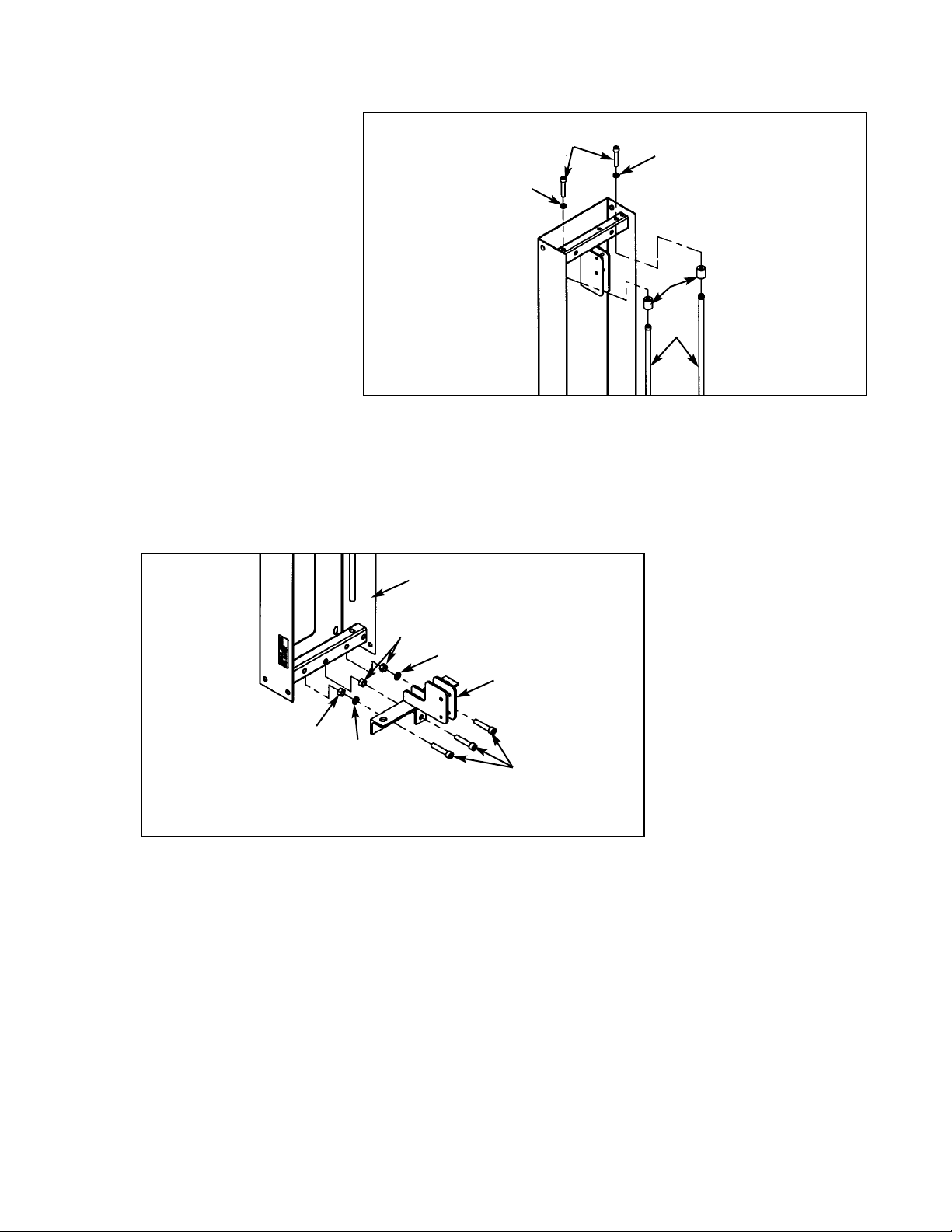
G. Locate the pulley mount (#59), three SHCS .500-13 x 2.50 (#76), three split lockwashers
.500 (#57) and three hex nuts .500-13 (#13).
H. Attach pulley mount (#59) to column as shown in Figure 8. Securely tighten hardware.
Figure 8
76
57
13
13
57
F. Remove both SHCS .500-
13 x 2.50 #76), both split
lockwashers (#57) and both
guide rod collets (#60)
securing guide rods (#69).
Remove guide rods from
column.
Figure 7
I. Reinstall both guide rods. NOTE: Do not securely tighten guide rods at this time.
76
57
57
60
69
59
Column
Cybex Modular Owner’s Manual
Page 4-13
Page 68

82C
82E
82B
82E
82C
82C
82C
82D
82E
82B
82A
Shipping Block
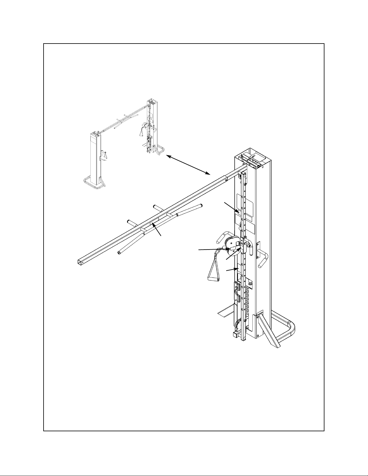
4. Attach column to the appropriate configuration (see steps 4A - 4E, Figures 9 and 10).
NOTE: For Free Standing configuration, see steps 4A - 4C then go to step 5.
For Tandem configuration see step 4D then go to step 5.
For Modular configurations see step 4E then to go step 5.
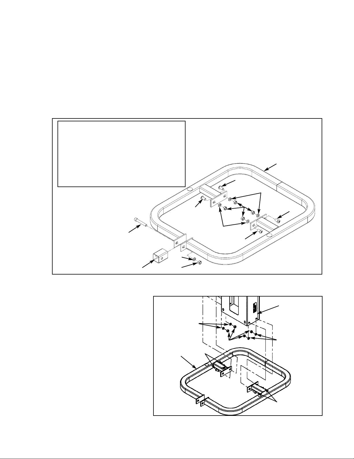
A. Place base (#82A) in area where the station will be used.
B. Remove the hardware from the base (#82A) as shown in Figure 9.
82A 1 5301-200 Base
82B 5 HN784000 Hex Nut .50-13
82C 4 JC780417 BHSCS .50-13 x 1.00
82D 1 JC782836 SHCS .50-13 x 3.25
82E 5 JS388300 Split Lockwasher .50
1 Shipping Block
ITEM QTY PART NO. DESCRIPTION
Figure 9
C. With an assistant, carefully place column into stabilizer (#82A) then attach hardware as shown
in Figure 10.
82C
82C
Figure 10
82B
82E
82E
82A
Column
Cybex Modular Owner’s Manual
Page 4-14
Page 69
D. For the Tandem configuration, attach both columns to frame as shown in the Tandem Center
Post & Dome Installation instruction sheet.
E. For the Modular configuration, install angle braces onto each column. See the exploded-view
diagram shown in the Modular Center Post Installation Instruction sheet
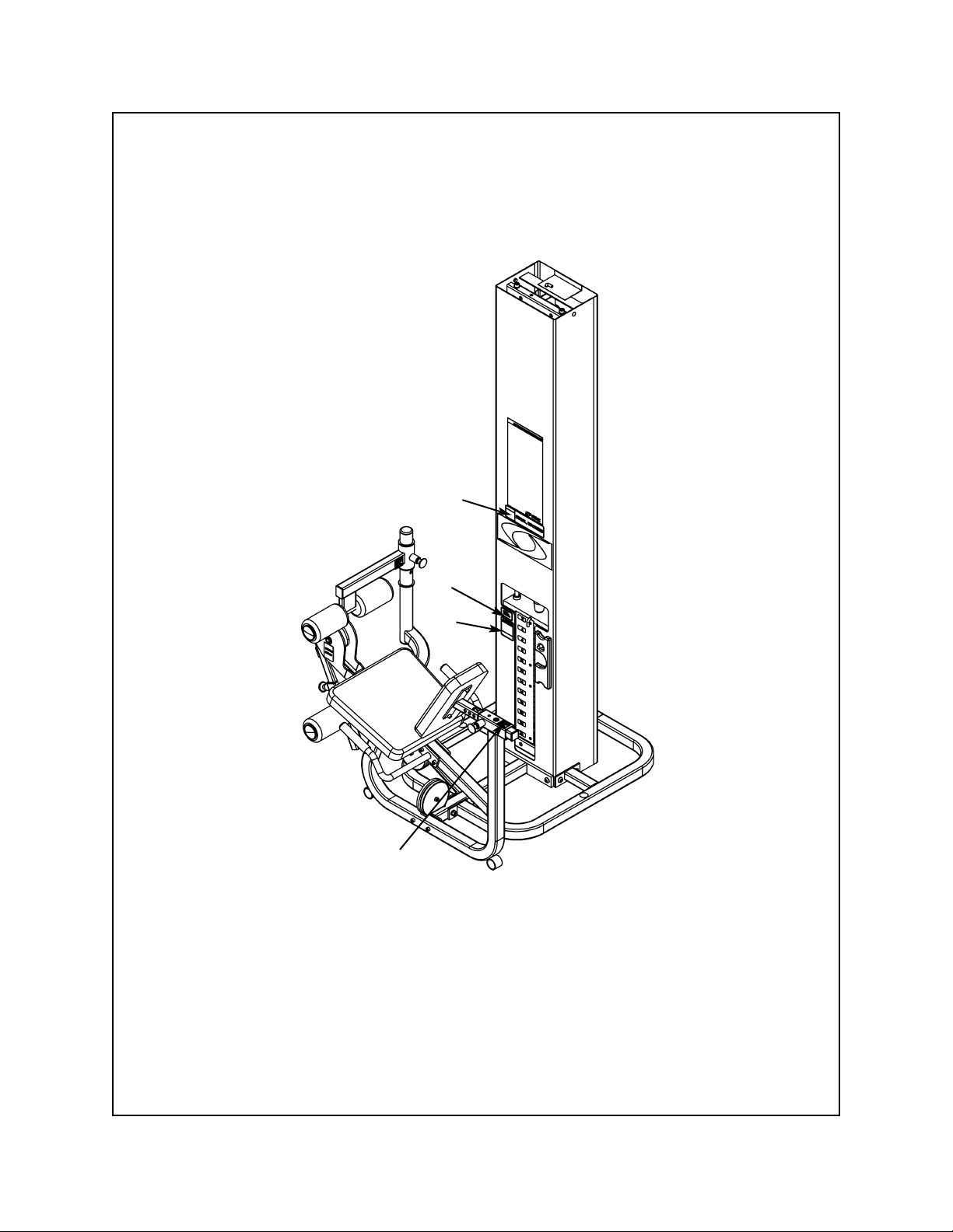
5. Install the Leg Press Assembly to the appropriate configuration (see steps 5A - 5F and
Figures 11 - 13B).
A. Locate the Leg Press assembly and hardware pack.
B. Verify contents of hardware pack. See Figure 11.
Figure 11
13 2 HN784000 Hex Nut .50-13
29 2 JC702820 SHCS .375-16 x 1.25
37 2 JC780420 BHSCS .50-13 x 1.25
41 1 PP090211 Plastic Insert 1.500 Sq x 10-14 G
50 2 JC700917 FHSCS .375-16 x 1.00
57 2 JS388300 Split Lockwasher .500
77 2 PN660201 Hole Plug
ITEM QTY PART NO. DESCRIPTION
37
50
29
77
57
13
41
Cybex Modular Owner’s Manual
Page 4-15
Page 70
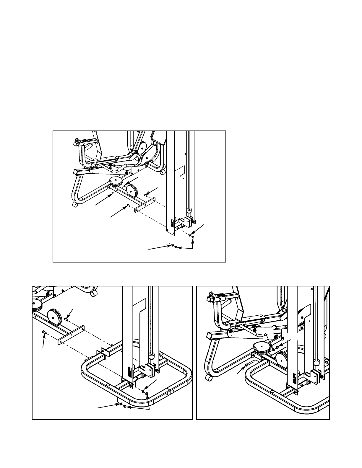
Figure 12
C. Locate two BHSCS .50-13 x 1.25 (#37), two split lockwashers (#57), two hex nuts .50-13
(#13) and two hole plugs (#77). For the Free Standing configuration, also locate (from step 4B)
one SHCS .50-13 x 3.25 (#82D), one split lockwasher .50 (#82E) and one hex nut .50-13
(#82B).
D. Install the Leg Press Assembly to the column. See Figure 12 for Modular/Tandem
configurations and Figures 13A and 13B for Free Standing configuration.
E. Install hole plugs (#77) to the Leg Press Assembly (Modular/Tandem configurations only). See
Figure 12.
Figure 13A
Figure 13B
82D
82E
82B
77
77
57
57
13
37
37
57
57
13
37
37
Cybex Modular Owner’s Manual
Page 4-16
Page 71

F. For Modular configuration only, see step 4 of the Modular Center Post installation instructions,
part number 55600.
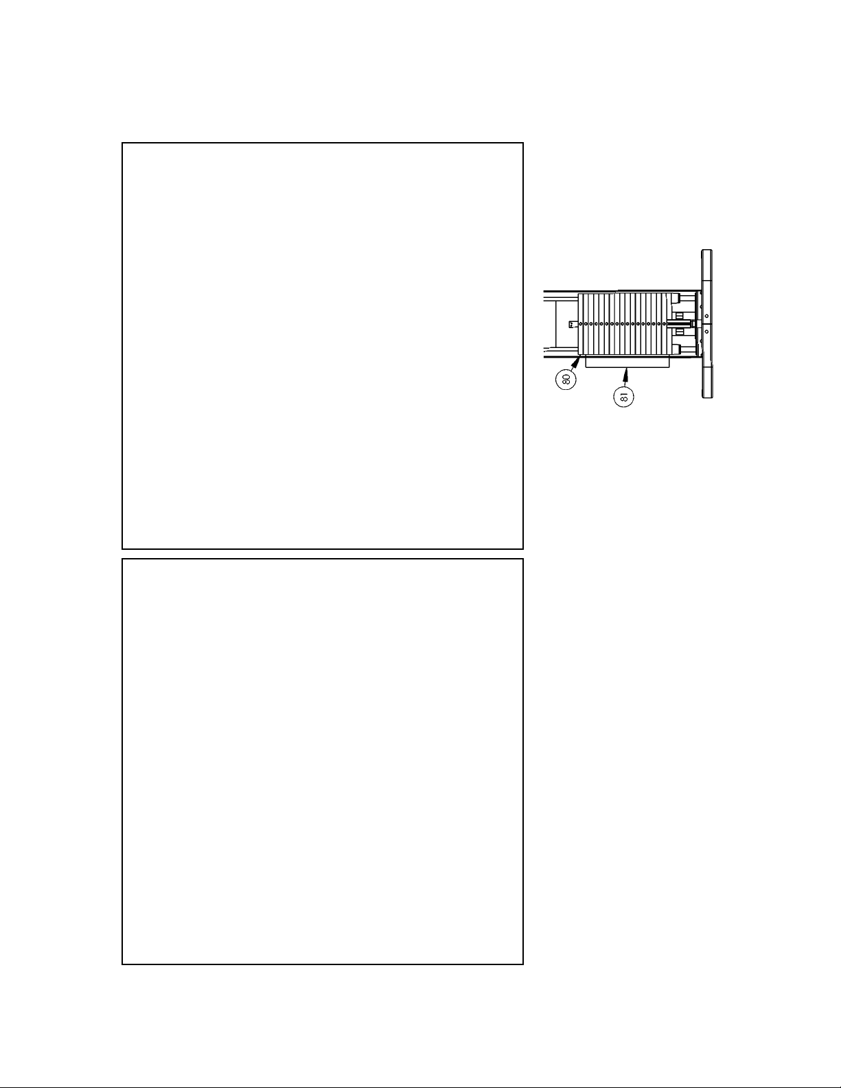
6. Install weight stack (see steps 6A - 6M, Figures 14 and 15).
A. Locate the half weight pin (#61), BHSCS .250-20 x .75 (#75) and split lockwasher (#73) from
the column hardware pack shown in Figure 5.
B. Install the half weight peg as shown in Figure 14.
Figure 14
C. Locate the top weight package and verify the contents. See Figure 15.
2 1 4800-250 Top Weight Assembly
8 1 HP286819 Spiral Pin
12 1 4700M005 Rubber Boot
14 1 5310P044 Weight Selector Pin
21 1 C-ZA00200 Half Weight
ITEM QTY PART NO. DESCRIPTION
Figure 15
75
73
61
2
12
8
14
21
Cybex Modular Owner’s Manual
Page 4-17
Page 72

D. Verify that you received the appropriate number of weight plates.
E. Remove the two SHCS securing the guide rods.
F. Carefully lean guide rods away from column.
G. Remove guide rod collets and plastic caps.
H. Wipe guide rods clean over entire length. Lubricate with light coating of medium weight
automotive engine oil.
I. Install each weight plate one at a time.
J. Install top weight.
K. Replace plastic caps and guide rod collets on guide rods.
L. Return guide rods to full upright position.
M. Insert both SHCS that were removed in step 6A.
NOTE: Do not secure top weight at this time.
Cybex Modular Owner’s Manual
Page 4-18
Page 73

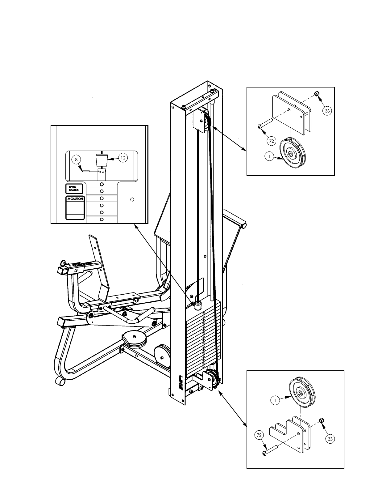
7. Routing Cable - Modular/Tandem configuration
only (see steps 7A - 7I, Figures 16 and 17).
NOTE: For Free Standing configuration see
step 8.
A. Install upper assemblies to any stations within
the Modular/Tandem configuration that
contain upper assemblies. See the Modular
and Tandem installation instructions.
B. Locate two pulleys (#1), two BHSCS .375-16 x
2.50 (#72) and two nylon locknuts .375-16
(#33).
C. At the same time, install pulley to lower pulley
bracket and route cable using one pulley (#1),
one BHSCS .375-16 x 2.50 (#72) and one
nylon locknut .375-16 (#33). See Figure 16.
D. Route cable to upper pulley bracket and
install pulley/route cable using one pulley (#1),
one BHSCS .375-16 x 2.50 (#72) and one
nylon locknut .375-16 (#33). See Figure 16.
E. Route cable downward to top plate.
F. Slide rubber boot (#12) onto cable end. See
Figures 16 and 17.
G. Insert cable end into top weight and align
cable fitting opening with opening in top
weight for proper cable tension as shown in
Figure 17. See the Owner’s Manual for proper
cable adjustment.
H. Using a hammer, drive roll pin (#8) through top
plate connector and cable fitting. Assure pin is
flush with top plate collar.
I. Insert selector pin into each weight plate to
assure proper alignment. See the Cable
Adjustment and Installation section of the
Owner’s Manual if the selector pin does not fit
smoothly or if cable appears to have
excessive slack.
1
72
33
33
72
1
Figure 17
12
8
Cybex Modular Owner’s Manual
Page 4-19
Page 74

Figure 18
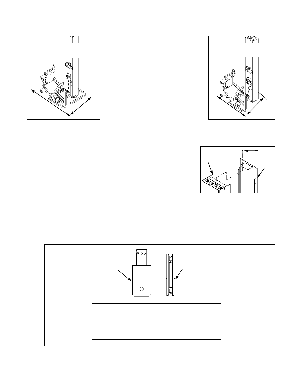
8. Routing Cable - Free Standing configuration only (see steps 8A - 8J and Figures 18 - 22).
A. Locate the back cover (#66), two pulleys (#1), two BHSCS .375-16 x 2.50 (#72), two nylon
locknuts .375-16 (#33), two stop brackets (#68)/bumpers (#42) and two pulley guards (#67).
B. Route cable through lower slot in back cover (#66) and place back cover onto back of
column. See Figure 18.
C. With top part of back cover (#66) leaned back, route cable/install pulley (#1) using one
BHSCS .375-16 x 2.50 (#72) and one nylon locknut .375-16 (#33). See Figure 19.
Figure 19
66
NOTE:Route cable through
back cover onto back
of column.
Cable
Cable
1
72
33
66
Cybex Modular Owner’s Manual
Page 4-20
Page 75

D. Install lower pulley using one pulleys (#1), one BHSCS .375-16 x 2.50 (#72), one nylon
locknut .375-16 (#33), two stop brackets (#68)/bumpers (#42) and two pulley guards (#67).
See Figure 20.
Figure 20
Figure 22
E. Route cable downward to top plate.
F. Slide rubber boot (#12) onto cable end. See Figure 21.
G. Insert cable end into top weight and align cable fitting
opening with opening in top weight for proper cable
tension as shown in Figure 21. See the Owner’s
Manual for proper cable adjustment.
H. Using a hammer, drive roll pin (#8) through top plate connector and cable fitting. Assure pin is
flush with top plate collar.
I. Insert selector pin into each weight plate to assure proper alignment. See the Cable
Adjustment and Installation section of the Owner’s Manual if the selector pin does not fit
smoothly or if cable appears to have excessive slack.
J. Secure back cover (#66) using weight selector pin (#71). See Figure 22.
1
33
67
67
68
42
42
68
72
71
66
Figure 21
12
8
Cybex Modular Owner’s Manual
Page 4-21
Page 76

9. Install Weight Plate Decal and Half Weight
(see steps 9A - 9H, Figures 23 and 24).
A. Locate the weight plate decals.
B. Place weight plate decals on weight plates
according to steps listed below and
Figures 23 and 24.
C. Slowly and carefully peel off back side of
decal. NOTE: When peeling off back cover,
make sure that the decals remain attached to
the front sticker.
D. Align holes in decal with appropriate holes in
weight stack. NOTE: Do not allow the
adhesive to touch weight stack at this time.
E. Insert a guide pin through each hole of the
template. NOTE: A guide pin can be any-
thing that fits through the weight stack hole,
such as a weight stack selector pin.
F. Carefully align decal and rub it onto weight
plates.
G. Carefully remove front side, leaving decals
adhering to weight plates. See Figure 24
H. Locate half weight and install it on the half weight peg.
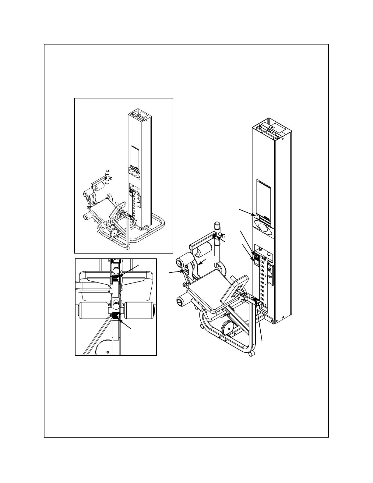
10. Install the back and seat cushions (see steps 10A - 10I and Figures 25 - 28).
A. Locate the cushion box and verify the contents as shown in Figure 25.
Figure 23
Decal
Weight Stack
Guide Rod
Figure 24
Figure 25
6
9
Cybex Modular Owner’s Manual
Page 4-22
Page 77

Figure 26
D. Locate seat cushion bracket, back cushion (#6), seat cushion (#9), two FHSCS .375-16 x 1.00
(#50) and two SHCS .375-16 x 1.25 (#29).
E. Install seat and back cushions as shown in Figure 27.
Figure 27
B. Locate the back cushion (#6), seat cushion (#9), two SHCS. .375-16 x 1.25 and two FHSCS
.375-16 x 1.00.
C. Remove the SHCS and nylon locknut securing the cushion post. See Figure 26.
Nylon
Locknut
SHCS
Cushion
Post
6
9
29
29
50
50
Cybex Modular Owner’s Manual
Page 4-23
Page 78

F. Locate plastic insert (#41).
G. Install cushion assembly onto frame.
H. Secure cushion assembly using SHCS and hex nut (removed from step 10C). See Figure 27.
I. Install plastic insert as shown in Figure 28.
41
Nylon
Locknut
SHCS
Figure 28
11. Verify proper operation.
Cybex Modular Owner’s Manual
Page 4-24
Page 79

12. Verify warning decals are present and not damaged (see decals below and Figure 28).
A
D
B
C
Cybex Modular Owner’s Manual
Page 4-25
WARNING
Notify floor staff if plates are
elevated or jammed to avoid
injury.
02521 A
Page 80
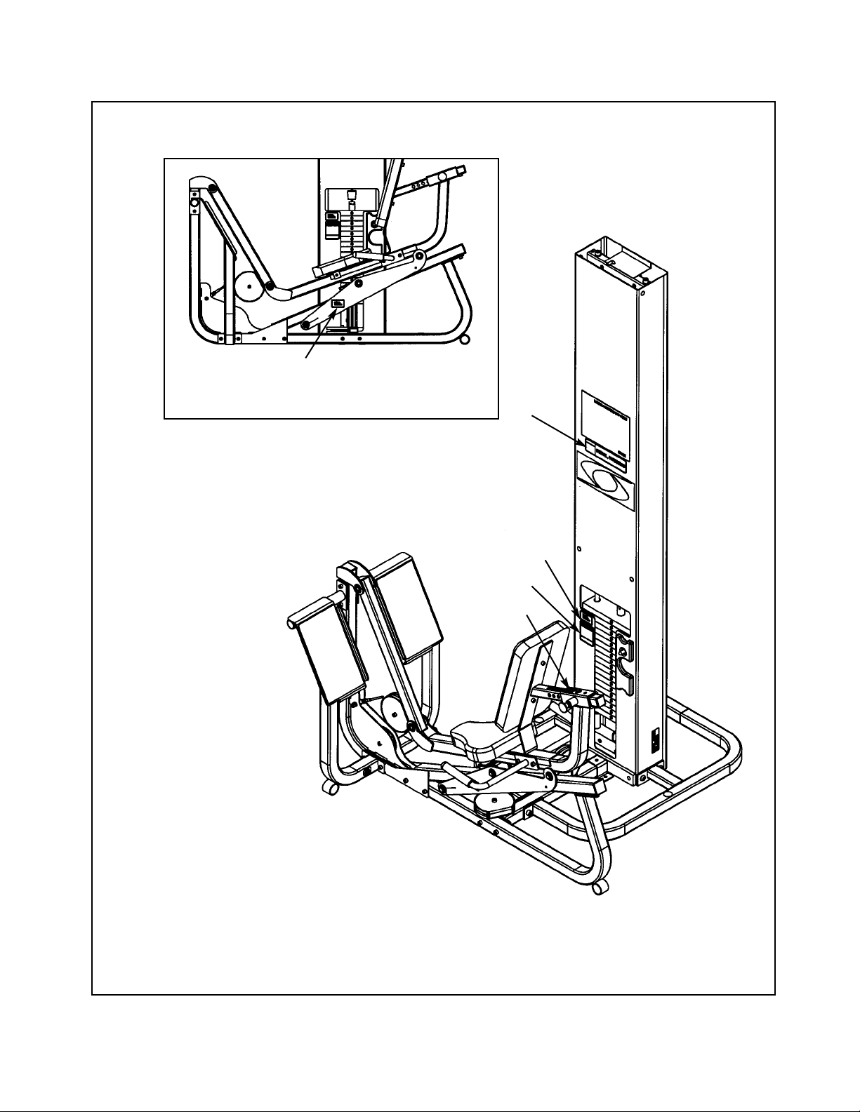
A. Warning Decal ................... 4000Y316
B. Caution Decal .................... 4000Y316
C. Warning Decal ................... 4800-381
D. Caution Decal .................... 8500-025
DESCRIPTION PART NO.
D
Figure 28
A
B
C
C
Cybex Modular Owner’s Manual
Page 4-26
Page 81
1 2 08014 Pulley
6 1 4106S055-0 Back Cushion
13 5 HN784000 Hex Nut .50-13
16 1 8630-202 Seat Tube
29 2 JC702820 SHCS .375-16 x 1.25
33 3 HN704901 Nylon Locknut .375-16
34 1 JC702814 SHCS .375-16 x .625
37 2 JC780420 BHSCS .50-13 x 1.25
41 1 PP090211 Plastic Insert 1.50 Sq x 10-14 G
50 2 JC700917 FHSCS .375-16 x 1.00
57 4 JS388300 Split Lockwasher .50
58 1 01243 Column
59 1 01247 Pulley Mount
60 2 01755 Guide Rod Collet
61 1 02106 Half Weight Peg
62 2 02330 Spacer 3.00 Weight
66 1 5301-201 Cover
• 67 2 5301-310 Pulley Guard
• 68 2 5301-311 Stop
69 2 5310M035 Weight Rod .625 Dia. x 85.31
70 1 55652 Instruction Modular Leg Press (not shown)
71 1 5310P044 Weight Select Pin
72 2 HC700430 BHSCS .375-16 x 2.50
73 1 HS308300 Split Lockwasher .25
74 2 HS760106 Flat Washer 1.75 x .68 x .140
75 1 JC620415 BHSCS .25-20 x .75
76 5 JC782830 SHCS .50-13 x 2.50
77 2 PN660201 Plug
78 2 PP080204 Plastic Cap .625 ID x .68 OD
79 2 PR060005 Bumper
80 17 4005C062 Weight Stack 4 x 12
81 1 4700-027 Top Weight Assembly
81B 1 4700M005 Rubber Boot (not shown)
81C 1 4800-256 Top Weight 18-4 x 12
81E 1 5310P044 Weight Selector Pin (not shown)
81G 1 C-ZA000200 Half Weight
• 82 1 5301-51 Modular Base Assembly
• 82A 1 5301-200 Base
• 82B 5 HN78400 Hex Nut .50-13
• 82C 4 JC780417 BHSCS .50-13 x 1.00
• 82D 1 JC782836 SHCS .50-13 x 3.25
• 82E 5 JS388300 Split Lockwasher .50
• 82F 2 PP080202 Plastic Insert 1.19 Dia. x 11 G
5322/5562 - Modular Seated Leg Press
ITEM QTY PART NO. DESCRIPTIONITEM QTY PART NO. DESCRIPTION
• For freestanding units only.
Cybex Modular Owner’s Manual
Page 4-27
Page 82
5362 - Modular/Tandem Configuration
Cybex Modular Owner’s Manual
Page 4-28
Page 83
5322 - Free Standing Configuration
Cybex Modular Owner’s Manual
Page 4-29
Page 84
Cable Routing
Cybex Modular Owner’s Manual
Page 4-30
Page 85

Cybex Modular Owner’s Manual
Page 4-31
Modular Leg Extension/Leg Curl
5653 Modular/Tandem Configuration
5307 Free Standing Configuration
TOOLS REQUIRED
• 5/32” Allen wrench
• 7/32” Allen wrench
• 5/16” Allen wrench
• 3/8” Allen wrench
• 9/16” Socket/wrench
• 3/4” Socket/wrench
• Rubber mallet
• Step ladder
NOTE: A minimum of two people will be required to assemble the Leg Extension/Leg Curl.
1. Read and understand all instructions thoroughly before assembling the Leg Extension/Leg
Curl (LE/LC) (see steps A - C).
A. Locate the Modular Assembly & Service manual that you received with your order. If you did
not receive a manual contact Cybex Customer Service and ask for part number 55620.
B. If you are assembling the Leg Extension/Leg Curl station into a Tandem configuration, locate
and review the Tandem Center Post instructions contained with the Tandem configuration (this
sheet is also located in the Modular Assembly & Service manual). Skip step 1 in the Tandem
Center Post instructions.
C. If you are assembling the Leg Extension/Leg Curl station into a Modular configuration, locate
and review the Modular Center Post instructions contained with the Modular configuration.
Skip step 1 in the Modular Center Post instructions.
2. Verify you have received the appropriate configuration (see steps 2A - 2C, Figures 1 and 2).
• Hammer
• Utility knife
• Automotive engine oil
Assembly Instructions
Unpacking
A. If you ordered the Modular/Tandem
configuration (5653):
Shipping Package Part Number
• LE/LC Column 5653-9x
• LE/LC Package 5653-50
• Weight Package 4700S040
• Weight Package 4700S043
• Top Weight Package 4700-010
• Cushion Set 8640-011
B. If you ordered the Free Standing
configuration (5307):
Shipping Package Part Number
• LE/LC Column 5307-9x
• LE/LC Package 5653-50
• LE/LC Stabilizer 5302-51
• Weight Package 4700S040
• Weight Package 4700S043
• Top Weight Package 4700-010
• Cushion Set 8640-011
Page 86
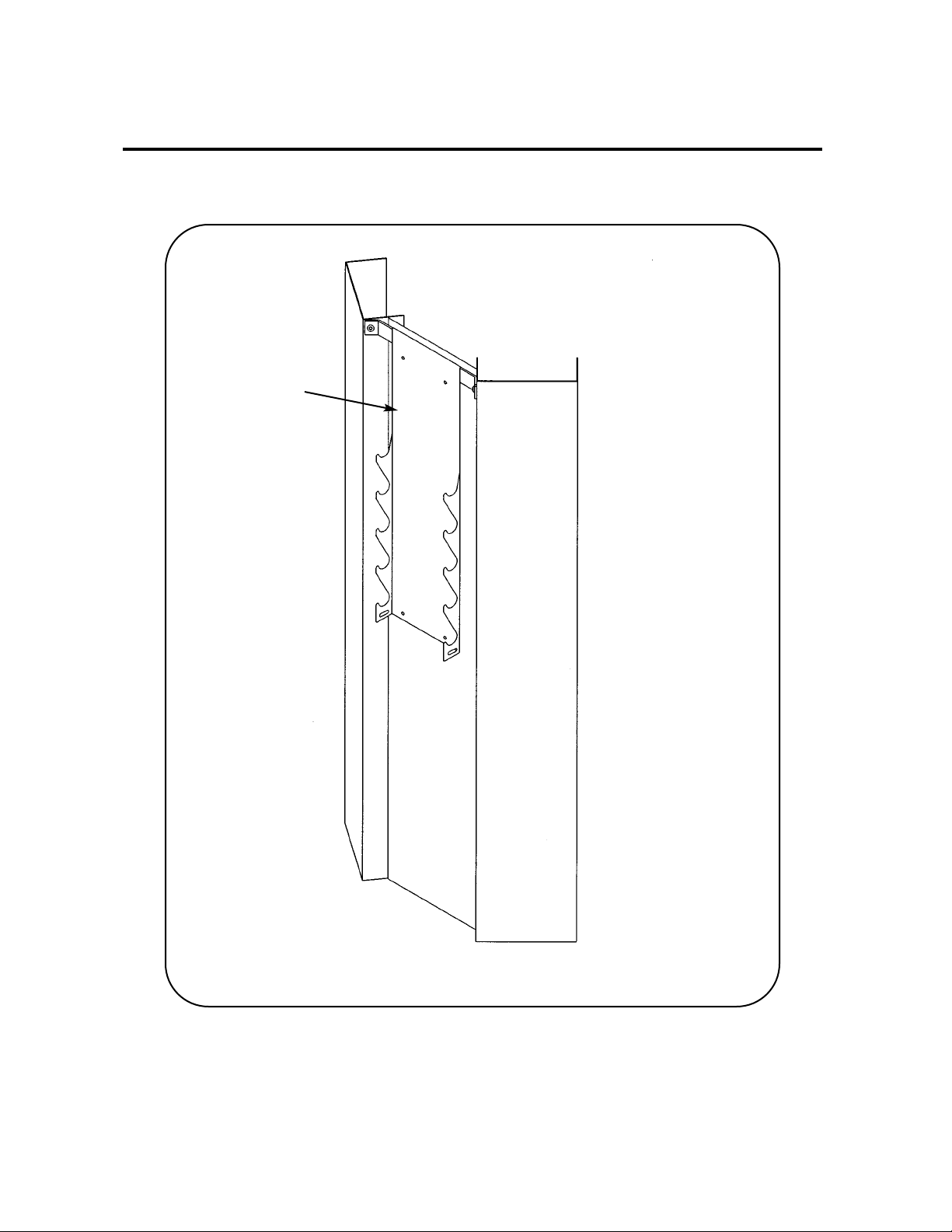
3. Unpack the carton containing the column (see steps 3A - 3F and Figures 3 - 7).
A. Locate and open the Leg Extension/Leg Curl Column carton.
B. The column (#78) should be laying so that the back side is
facing upward.
C. For Free Standing units containing a back cover, remove the
BHSCS .375-16 x 2.00 (#69) securing the back cover (#74).
Remove back cover by sliding it then lifting it upward. See
Figure 3.
D. Remove any shipping supports and the carton located inside the column.
E. Verify contents of the carton. See Figure 4.
Figure 3
69
78
74
Figure 1
Figure 2
C. Carefully place shipping
packages near area of
installation.
D. For Free Standing configurations,
allow a minimum amount 88” x
76”. See Figure 1.
E. For Modular/Tandem
configurations, allow a minimum
of 88” x 67”. See Figure 2.
1 3 08014 Pulley Assembly 4.50
40 1 02120 Pulley Mount
1 Hardware Pack
1 Hardware Pack
ITEM QTY PART NO. DESCRIPTION
40
1
Figure 4
88”
76”
88”
67”
Minimum space required
during operation.
Minimum space required
during operation.
Cybex Modular Owner’s Manual
Page 4-32
Page 87
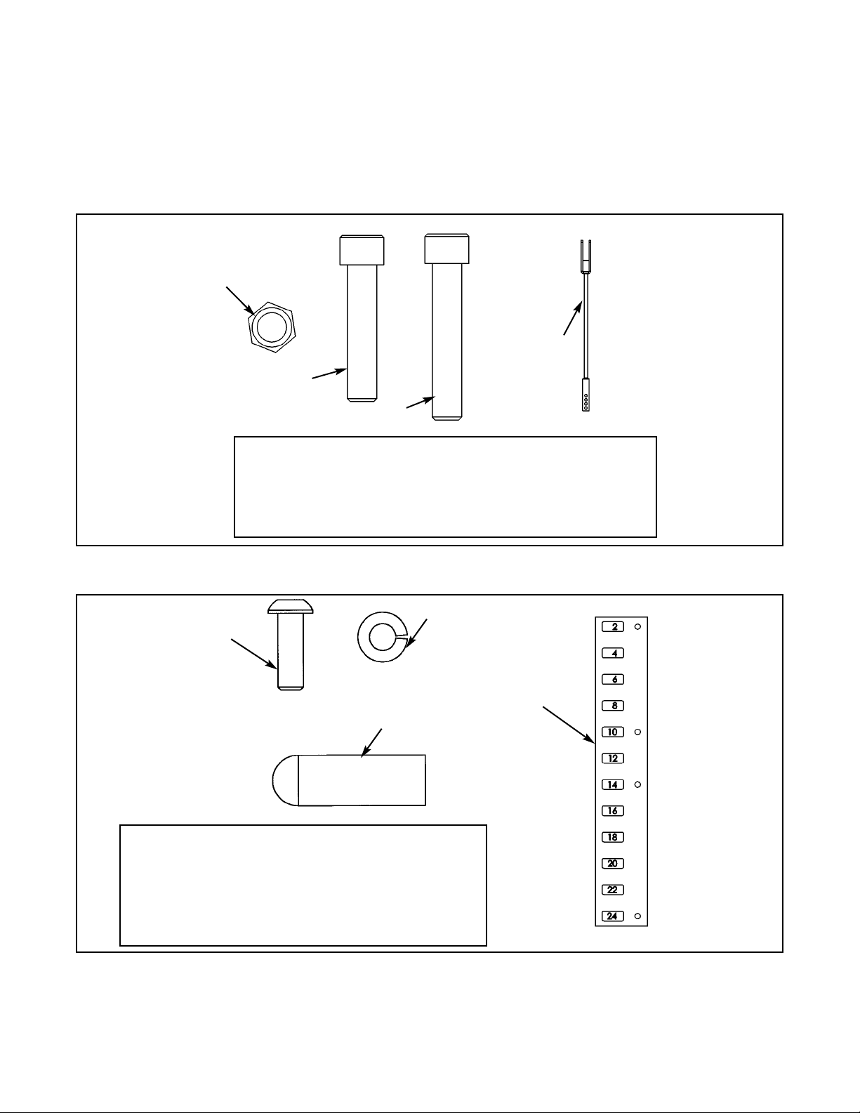
Figure 5
26 1 HC702826 SHCS .375-16 x 2.00
29 3 JC702824 SHCS .375-16 x 1.75
53 1 5653-003 Weight Stack Cable
57 4 HN704901 Nylon Locknut .375-16
ITEM QTY PART NO. DESCRIPTION
57
26
29
F. Remove both hardware packs from the carton and verify the contents of each. See
Figures 5 - 7.
NOTE: Figures 5 and 6 are for the Free Standing configuration.
Figures 6 and 7 are for the Tandem/Modular configuration.
Figure 6
67 1 02106 Half Weight Peg
73 1 4800-515 Weight Plate Decal
82 1 HS308300 Split Lockwasher .25
84 1 JC620415 BHSCS .25-20 x .75
1 55653 Assembly Instructions
ITEM QTY PART NO. DESCRIPTION
82
67
84
73
53
Cybex Modular Owner’s Manual
Page 4-33
Page 88
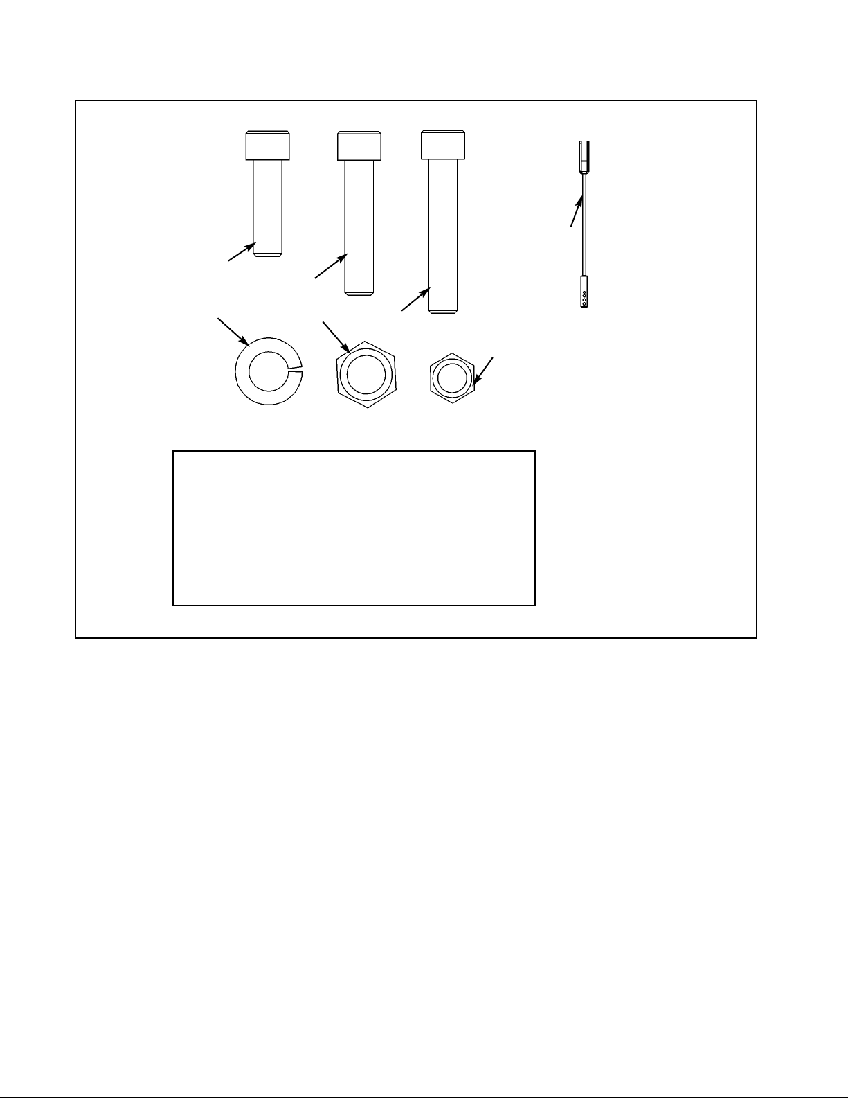
Figure 7
26 1 HC702826 SHCS .375-16 x 2.00
29 3 JC702824 SHCS .375-16 x 1.75
53 1 5653-003 Weight Stack Cable
57 4 HC704901 Nylon Locknut .375-16
59 4 JC702820 SHCS .50-13 x 1.25
64 4 HN784000 Hex Nut .50-13
87 4 JS388300 Split Lockwasher .50
ITEM QTY PART NO. DESCRIPTION
59
29
26
57
64
87
53
Cybex Modular Owner’s Manual
Page 4-34
Page 89
4. Attach column to the appropriate configuration (see steps 4A - 4F, Figures 8 and 9).
NOTE: For Free Standing configuration, see steps 4A - 4C then go to step 5.
For Tandem configuration see step 4D and 4E then go to step 5.
For Modular configurations see step 4D and 4F then go to step 5.
A. Place the base assembly (#65) in area where the station will be used.
B. Remove the hardware from the base (#65A) as shown in Figure 8.
65 1 5302-51 Base Assembly
65A 1 5301-200 Base
65B 5 HN784000 Hex Nut .50-13
65C 4 JC780417 BHSCS .50-13 x 1.00
65D 1 JC782836 SHCS .50-13 x 3.25
65E 5 JS388300 Split Lockwasher .50
1 Shipping Block
ITEM QTY PART NO. DESCRIPTION
Figure 8
C. With an assistant, carefully place
column (#78) into stabilizer
(#65A) then attach hardware as
shown in Figure 9.
65C
65C
Figure 9
65B
65E
65C
65E
65B
65E
65C
65C
65C
65D
65E
65B
65A
Shipping Block
65E
65A
78
Cybex Modular Owner’s Manual
Page 4-35
Page 90

D. For Tandem and Modular configurations, locate four SHCS .50-13 x 1.25 (#59), four split
lockwashers .50 (#87) and four hex nuts .50-13 (#64). See Figure 7 (hardware pack).
E. For the Tandem configuration, using the hardware located in step 4D, attach both columns to
frame as shown in the Tandem Center Post & Dome Installation instruction sheet.
NOTE: The generic column shown in the Tandem and Modular instruction sheets will slightly
differ in appearance than the Leg Extension/Leg Curl Column (an angle bracket is used
instead of a tube).
F. For the Modular configuration, using the hardware located in step 4D, install angle braces
onto each column. See the exploded-view diagram shown in the Modular Center Post
Installation Instruction sheet.
5. Install the Leg Extension/Leg Curl Assembly to the appropriate configuration (see steps 5A 5F and Figures 10 - 12B).
A. Locate the Leg Extension/Leg Curl assembly and hardware pack.
B. Verify contents of hardware pack. See Figure 10.
Figure 10
38 1 HP286819 Spiral Pin
39 1 8640-330 Spring Pin 10 mm x 90 mm Black
60 2 JC780420 BHSCS .50-13 x 1.25
61 2 PN660201 Hole Plug
64 2 HN784000 Hex Nut .50-13
87 2 JS388300 Split Lockwasher .50
90 2 JC702820 SHCS .375-16 x 1.25
ITEM QTY PART NO. DESCRIPTION
87
39
60
64
38
64
61
Cybex Modular Owner’s Manual
Page 4-36
Page 91
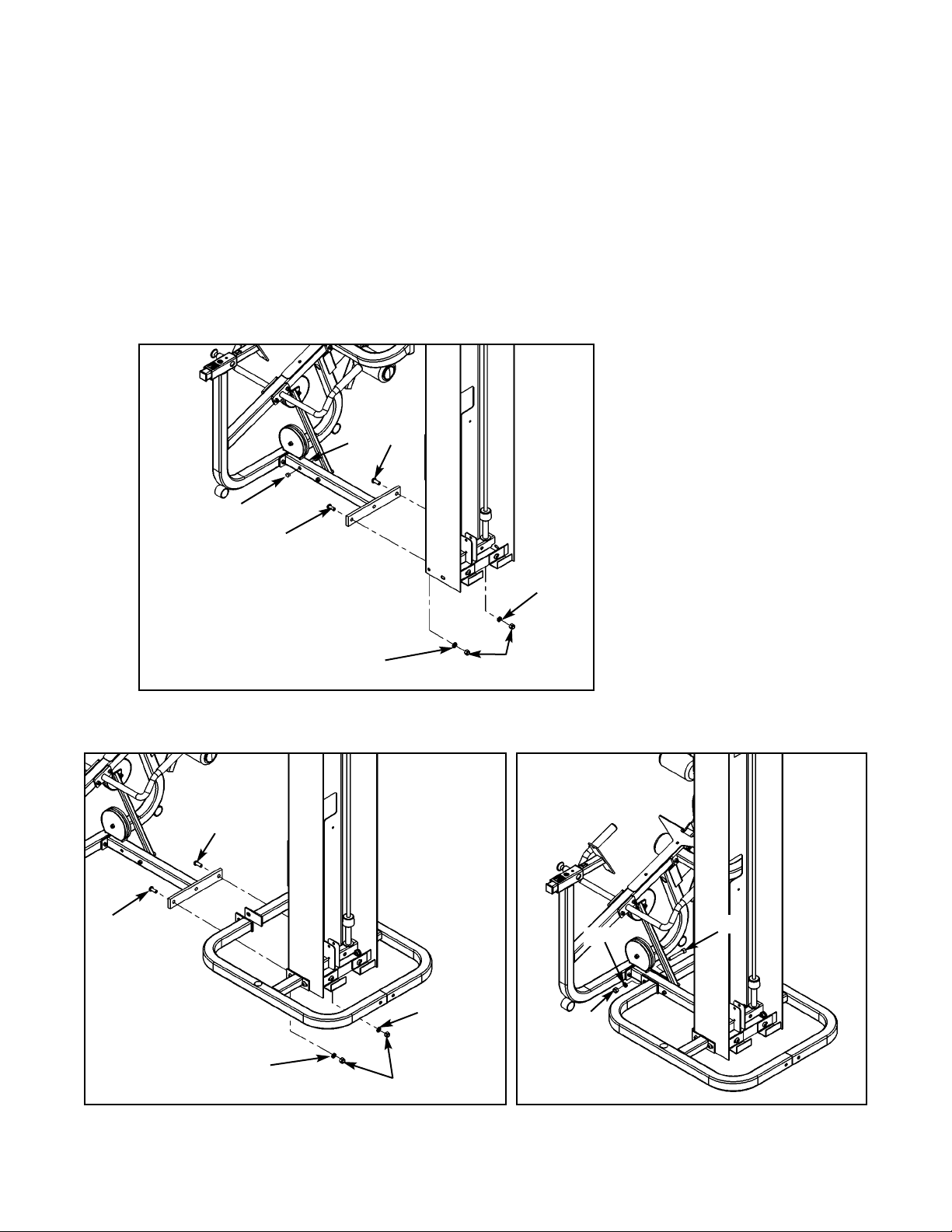
Figure 11
C. Locate two BHSCS .50-13 x 1.25 (#60), two split lockwashers .50 (#87), two hex nuts .50-13
(#64) and two hole plugs (#61). For the Free Standing configuration, also locate (from step 4B)
one SHCS .50-13 x 3.25 (#65D), one split lockwasher .50 (#65E) and one hex nut .50-13
(#65B).
D. Install the Leg Extension/Leg Curl Assembly to the column. See Figure 12 for
Modular/Tandem configurations and Figures 12A and 12B for Free Standing configuration.
E. Install hole plugs (#61) to the Leg Extension/Leg Curl Assembly (Modular/Tandem
configurations only). See Figure 11.
Figure 12A
Figure 12B
65B
65E
65D
60
60
87
87
64
60
60
87
87
64
61
61
Cybex Modular Owner’s Manual
Page 4-37
Page 92

F. For Modular configuration only, see step 4 of the Modular Center Post installation instructions,
part number 55600.
6. Install weight stack (see steps 6A - 6O, Figures 13 - 15).
A. Locate the half weight peg (#67), BHSCS .25-20 x .75 (#84) and split lockwasher (#82) from
the column hardware pack shown in Figure 5.
B. Install the half weight peg (#67) as shown in Figure 13.
Figure 13
C. Locate the top weight package and verify the contents. See Figure 14.
63 1 4700-010 Top Weight Assembly
63B 1 4700M005 Rubber Boot
63C 1 4700-307 Top Weight 20-4 x 12
63E 1 5310P044 Weight Selector Pin
63G 1 C-ZA00200 Half Weight
63H 1 HP286819 Spiral Pin
ITEM QTY PART NO. DESCRIPTION
Figure 14
84
82
67
63C
63B
63H
63E
63G
Cybex Modular Owner’s Manual
Page 4-38
Page 93

D. Verify that you received 20 weight plates.
E. Remove the two SHCS securing the guide rods.
F. Carefully lean guide rods away from column.
G. Remove guide rod collets and plastic caps.
H. Wipe guide rods clean over entire length. Lubricate with light coating of medium weight
automotive engine oil.
I. Install each weight plate one at a time. NOTE: Do not install the second weight and top
weight at this time.
J. Locate the spring pin 10 mm x 90 mm black (#39).
K. Slide the top weight plate onto second plate and carefully pound
the spring pin into the second weight plate hole, securing second
plate to the top plate. See Figure 15. NOTE: Insert pin so that it is
flush with the weight plate.
L. Install top weight.
M. Replace plastic caps and guide rod collets on guide rods.
N. Return guide rods to full upright position.
O. Insert both SHCS that were removed in step 6E (securing guide rods).
NOTE: Do not secure top weight at this time.
Figure 15
39
Pin
second
weight
Cybex Modular Owner’s Manual
Page 4-39
Page 94

Figure 16
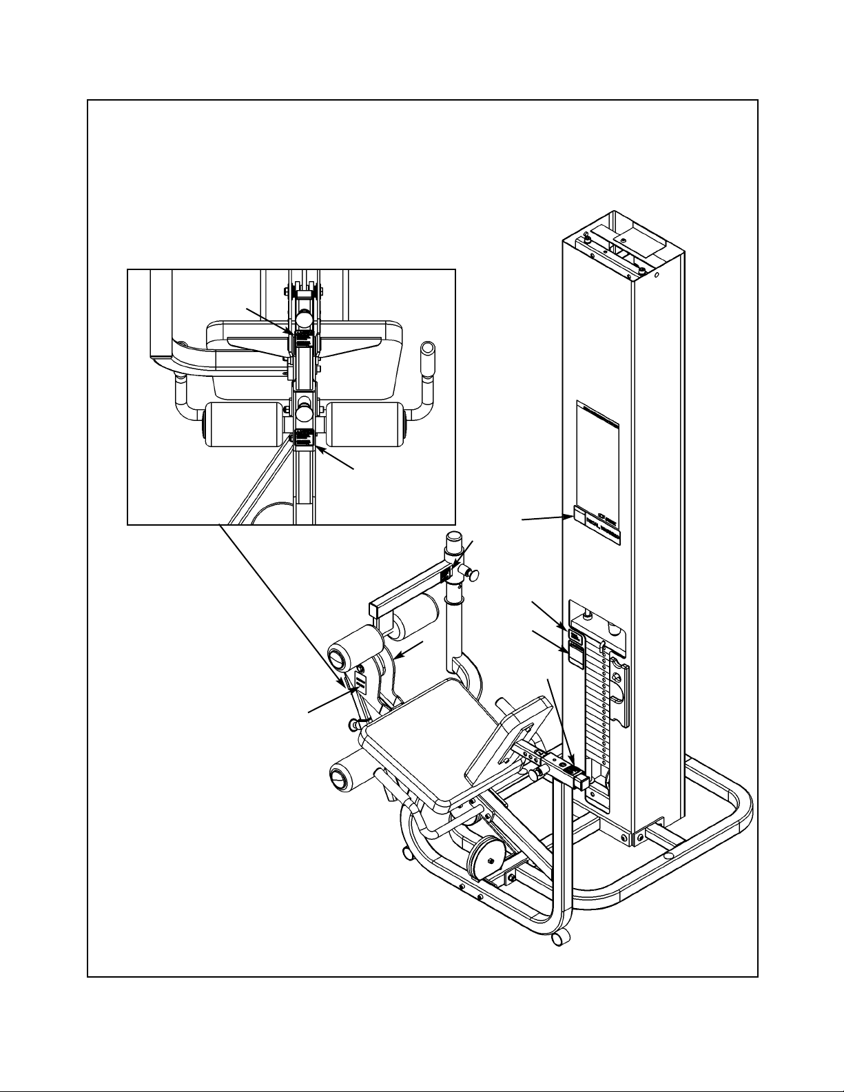
7. Routing Cable (see steps 7A - 7J and Figure 16).
A. Install upper assemblies to any stations within the
Modular/Tandem configuration that contain upper
assemblies. See the Modular and Tandem
installation instructions.
B. Locate weight stack cable (#53), four pulleys (#1),
pulley mount (#40), three SHCS .375-16 x 1.75
(#29), one SHCS .375-16 x 2.00 (#26) and four
nylon locknuts .375-16 (#57) and one spiral pin
(#38).
C. Route cable to inside of column (#78). See Figure
16, letter D.
D. At the same time, install pulley to lower pulley
bracket and route cable (#53) using one pulley
(#1), one SHCS .375-16 x 1.75 (#29) and one
nylon locknut .375-16 (#57). See Figure 16,
letter D. Set cable down.
E. Attach one end of the weight stack cable (#53) to
the frame as shown in Figure 16 (using one SHCS
.375-16 x 1.75 (#29) and one nylon locknut .37516 (#57). See Figure 16, letter E.
F. NOTE: Do not install hanging pulley in this step.
At the same time, route cable (#53) and install the
last pulley before the weight stack (using one
SHCS .375-16 x 1.75 (#29) and one nylon locknut
.375-16 (#57). See Figure 16, letter F.
G. Pick up the other cable and install the pulley
mount (#40). Drive a spiral pin (#63H) through
cable end and pulley mount as shown in Figure
16, letter G.
H. Wrap a portion of the weight stack cable (#53)
around the last pulley (#1) to be installed. At
the same time, route cable (#53) and install
pulley (#1) using one SHCS .375-16 x 2.00
(#26) and one nylon locknut (#57).
I. Route cable downward to top plate. Slide rubber
boot (#63B) onto cable. Drive a spiral pin through
top plate connector and cable end. The top
weight should be snug (just resting on the next
plate). See Figure 16, letter H.
J. Slide rubber boot over top weight connector.
1
53
57
57
29
1
29
1
26
57
53
38
C
D
I, J
E, F
G
63B
63H
78
40
NOTE:
See the Modular
Assembly & Service
Manual for proper roll
pin adjustment (if
necessary).
Cybex Modular Owner’s Manual
Page 4-40
Page 95

K. For Free Standing units, place back cover (#74) to column (#78) into position (bottom first)
and secure using the BHSCS .375-16 x 2.00 (#69) that was removed from step 3C. See
Figure 17.
Figure 17
69
74
78
Cybex Modular Owner’s Manual
Page 4-41
Page 96
8. Install Weight Plate Decal and Half Weight
(see steps 9A - 9H, Figures 19 and 20).
A. Locate the weight plate decals.
B. Place weight plate decals on weight plates
according to steps listed below and Figures
18 and 19.
C. Slowly and carefully peel off back side of
decal. NOTE: When peeling off back cover,
make sure that the decals remain attached to
the front sticker.
D. Align holes in decal with appropriate holes in
weight stack. NOTE: Do not allow the
adhesive to touch weight stack at this time.
E. Insert a guide pin through each hole of the
template. NOTE: A guide pin can be any-
thing that fits through the weight stack hole,
such as a weight stack selector pin.
F. Carefully align decal and rub it onto weight
plates.
G. Carefully remove front side, leaving decals
adhering to weight plates. See Figure 19.
H. Locate half weight and install it on the half weight peg.
10. Install the back and seat cushions (see steps 10A - 10I and Figures 20 - 21).
A. Locate the cushion box and verify the contents as shown in Figure 20.
Figure 18
Decal
Weight Stack
Guide Rod
Figure 19
Figure 20
36
37
11
33
Cybex Modular Owner’s Manual
Page 4-42
Page 97
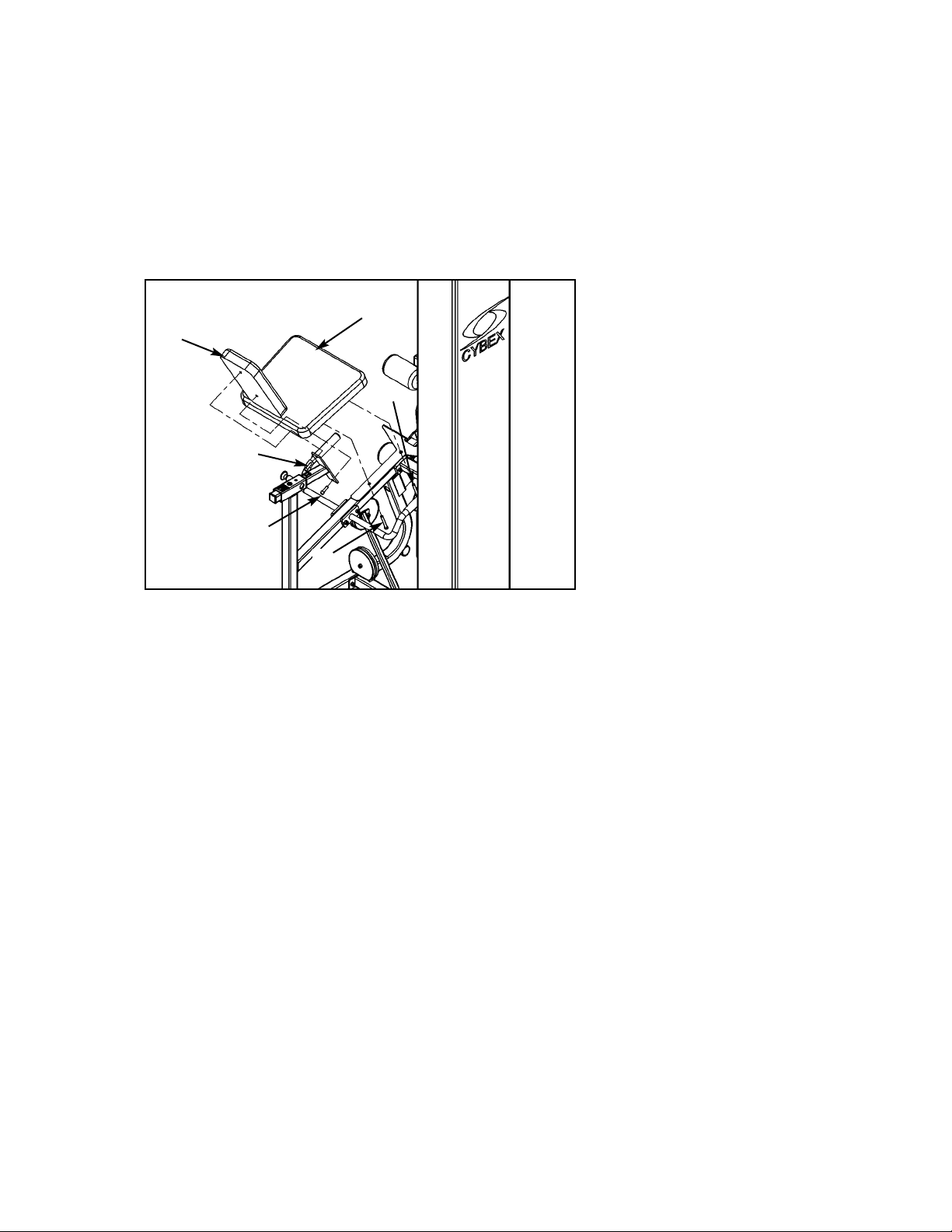
Figure 21
B. Locate the back cushion (#36), seat cushion (#37), four cushions 4.00 Dia. x 7.00 L x .875
(#11), four plastic inserts (#33) and two SHCS .375-16 x 1.25 (#59).
C. Install back cushion (#36) using two SHCS .375-16 x 1.25 (#59) as shown in Figure 21.
D. Install seat cushion (#37) using two SHCS .375-16 x 3.00 (#27) secured into the frame.
Remove the hex nut and washer then install each SHCS into the cushion. See Figure 21.
37
90
36
27
90
27
Cybex Modular Owner’s Manual
Page 4-43
Page 98

11. Verify proper operation.
12. Verify warning decals are present and not damaged (see decals below and Figure 22).
A
D
B
C
E
Cybex Modular Owner’s Manual
Page 4-44
WARNING
Notify floor staff if plates are
elevated or jammed to avoid
injury.
02521 A
Page 99
A. Warning Decal ................... 02521
B. Caution Decal .................... 4000Y316
C. Warning Decal ................... 4800-381
D. Caution Decal .................... 8500-025
E. Caution Decal .................... 8500-026
DESCRIPTION PART NO.
D
Figure 22
A
B
C
D
D
E
D
E
Cybex Modular Owner’s Manual
Page 4-45
Page 100

1 3 08014 Pulley
26 2 HC702826 SHCS .375-16 x 2.00
27 2 HC702834 SHCS .375-16 x 3.00
29 3 JC702824 SHCS .375-16 x 1.75
36 1 4800-021 Back Cushion
37 1 4800-015 Seat Cushion
38 1 HP286819 Spiral Pin
39 1 8640-330 Spring pin 10 mm x 90 mm Black
40 1 02120 Pulley Mount
53 1 5653-003 Weight Stack Cable
57 3 HN704901 Nylon Locknut .375-16
58 2 HN784900 Nylon Locknut .50-13
59 4 JC782820 SHCS .375-16 x 1.25
60 2 JC780420 BHSCS .50-13 x 1.25
61 2 PN660201 Hole Plug
62 20 4000C062 Weight Plate 4 x 12
63 1 4700-010 Top Weight Assembly
63A 2 4700-019 Bearing Flange .62 x .92 x 1.50 Lg
63B 1 4700M005 Rubber Cap
63C 1 4700-307 Top Weight 20-4 x 12
63D 1 4700M004 Cable Connector
63E 1 5310P044 Weight Selector Pin
63F 2 BR030206 Retaining Ring
63G 1 C-ZA000200 Half Weight
63H 1 HP286819 Spiral Pin
64 4 HN784000 Hex Nut .50-13
65 1 5302-51 Modular Base Assembly
65A 1 5301-200 Base
65B 5 HN784000 Hex Nut .50-13
65C 4 JC780417 BHSCS .50-13 x 1.00
65D 1 JC782836 SHCS .50-13 x 3.25
65E 5 JS388300 Split Loackwasher .50
66 2 01755 Guide Rod Collet - Long
67 1 02106 Half Weight Peg
69 1 HC700426 BHSCS .375-16 x 2.00
74 1 5310C029 Back Cover
75 2 5310M035 Weight Rod .625 Dia. x 85.31
78 1 5653-200 Column
79 2 5653-302 Weight Spacer 4.00
82 1 HS308300 Split Lockwasher
83 4 HS760106 Flat Washer 1.75 .688 .140 T
84 1 JC620415 BHSC .25-20 x .75
86 2 JC782830 SHCS .50-13 x 2.50
87 6 JS388300 Split Lockwasher .50
88 2 PP080204 Plastic Cap .625 ID x .68 OD
89 2 PR060005 Bumper Weight
90 2 JC7082820 SHCS .375-16 x 1.25
5307/5653 - Leg Extension/Leg Curl Station
ITEM QTY PART NO. DESCRIPTION ITEM QTY PART NO. DESCRIPTION
Cybex Modular Owner’s Manual
Page 4-46
 Loading...