

Page 1

Cybex 525AT Arc Trainer
Service Manual
Cardiovascular Systems
Part Number 525AT-901 -
®
www.cybexintl.com
Page 2

Cybex Service Manual
Table of Contents
FCC Compliance Information ............. 3
Safety
Ground and Voltage Information........... 4
Important Safety Instructions ............. 4
Warning and Caution Decals ............. 6
Maintenance
Warnings ............................9
Preventive Maintenance Activities ........ 10
Cleaning Unit ........................ 10
Remove Access Cover ................. 11
Drive Belts .......................... 12
Attach Access Cover .................. 12
E3 View Monitor ...................... 13
Recommended Service Schedule ........ 13
Customer Service
Product Registration................... 15
Contacting Service .................... 15
Ordering Parts ....................... 15
Return Material Authorization (RMA) ......16
Damaged Parts....................... 16
Service
Console Display . . . . . . . . . . . . . . . . . . . . . . 17
User Controls . . . . . . . . . . . . . . . . . . . . . . . . 18
User Control Symbols Used ............. 19
Setup .............................. 20
Service Diagnostics ................... 22
Error Codes ......................... 23
Linkage Rod ......................... 25
Arm Handle Linkage................... 26
Foot Plate Assembly................... 26
Front Foot Plate Arm .................. 27
Rear Foot Plate Arm................... 27
Arm Handle.......................... 30
Crank Covers . . . . . . . . . . . . . . . . . . . . . . . . 34
Shrouds ............................ 34
Control Board ........................ 35
Crank Arms.......................... 35
Crank Shaft Assembly ................. 35
Counterweights....................... 36
Lower Pivot Assembly ................. 36
Incline Motor......................... 41
Accessory Tray....................... 48
Contact Heart Rate Grips ............... 52
LED Display Board .................... 54
E3 View Monitor ...................... 58
MCC Board.......................... 64
Update Software...................... 69
Appendix – Schematic
Schematic 525AT ..................... 73
Cybex® and the Cybex logo are registered trademarks of Cybex International, Inc. Polar® is a registered trademark of Polar Electro Inc. iPOD® is
registered trademark of Apple.
DISCLAIMER: Cybex International, Inc., makes no representations or warranties regarding the contents of this manual. We reserve the right to revise
this document at any time or to make changes to the product described within it without notice or obligation to notify any person of such revisions or
changes.
© Copyright 2013, Cybex International, Inc. All rights reserved. Printed in the United States of America.
10 Trotter Drive Medway, MA 02053 • 508-533-4300 • FAX 508-533-5183 • www.cybexintl.com • 525AT-901 - • July 2013
2
Page 3

Cybex Service Manual
FCC Compliance Information
Changes or modications to this unit not expressly approved by the party responsible for compliance
could void the user’s authority to operate the equipment!
This equipment has been tested and found to comply with the limits for a Class B digital device,
pursuant to part 15 of the FCC Rules. These limits are designed to provide reasonable protection
against harmful interference in a residential installation. This equipment generates, uses and can
radiate radio frequency energy and, if not installed and used in accordance with the instructions, may
cause harmful interference to radio communications. However, there is no guarantee that interference
will not occur in a particular installation. If this equipment does cause harmful interference to radio
or television reception, which can be determined by turning the equipment off and on, the user is
encouraged to try to correct the interference by one or more of the following measures:
• Reorient or relocate the receiving antenna.
• Increase the separation between the equipment and receiver.
• Connect the equipment into an outlet on a circuit different from that to which the receiver is
connected.
• Consult the dealer or an experienced radio/TV technician for help.
3
Page 4

Cybex Service Manual
Safety
Read all instructions and warnings before using.
Ground and Voltage Information
WARNING: Shock and electrocution hazard
• Connect unit to a grounded outlet.
• Do not use voltage adapter or extension cord.
Cybexisnotresponsibleforinjuriesordamagesasaresultofcordorplugmodication.
• Verify voltage requirements of unit match local voltage requirements.
• Verify unit outlet is the same conguration as the plug.
115VAC EuroPlug UK230VAC Japanese Danish Australia
NEMA5-15 CEE7/7 BS1363 JIS8303 107-2-D1 AS/NZS3112
Important Safety Instructions
(Save These Instructions)
WARNING: Shock and electrocution hazard
• Unplug unit and let sit 10 minutes before cleaning or performing maintenance
• Electrical charge can remain in unit after unplugging
• Keep water and liquids away from electrical parts
UserSafetyPrecautions
• KEEP ALL CHILDREN 12 AND UNDER AWAY! Teenagers or disabled must be supervised.
• Obtain a medical exam before beginning any exercise program.
• Stop exercising if feeling faint, dizzy, or experiencing pain and consult your physician.
• Obtain instruction before using.
• Read and understand all warnings posted on the unit before using.
• Use the handrails for support and to maintain balance.
• Wait until foot plates come to a complete stop before dismounting.
4
Page 5

• Keep foot plate surface clean and dry.
• DO NOT wear loose or dangling clothing while using.
• Keep all body parts and other items free and clear of moving parts.
• DO NOT use unit if user exceeds 400 lbs. (180 kg). This is the rated maximum user weight.
• Report any malfunctions, damage or repairs to the facility.
• Replace any warning labels if damaged, worn or illegible.
FacilitySafetyPrecautions
It is the sole responsibility of the user/owner or facility operator to ensure that regular maintenance is
performed.
• Enforce all user and safety precautions.
• Read and understand the Owner’s Manual completely before assembling, servicing or using unit.
• Verify all users are properly trained on using the equipment.
• Do not use unit outdoors.
• Verify that each unit is setup, leveled and operated on a solid level surface. Do not install equipment
on an uneven surface.
• Verify there is enough room for safe access and operation of unit.
• Do not use the unit if: (1) the unit is plugged into an optional power adapter that has a damaged
cord; (2) the unit is not working properly or (3) if the unit has been dropped or damaged. Seek
service from a qualied technician.
• EQUIPMENT is not suitable for use in the presence of aerosol (spray), FLAMMABLE
ANAESTHETIC MIXTURE WITH AIR or WITH OXYGEN or NITROUS OXIDE.
• Perform regular maintenance checks on unit. Performance level can be maintained only if
examined regularly. Pay close attention to all areas most susceptible to wear, including (but not
limited to) cables, pulleys, belts and grips.
• Replace any warning labels if damaged, worn, or illegible.
• Immediately replace worn or damaged components. If unable to immediately replace worn or
damaged components, then remove unit from service until repair is made.
• Do not attempt electrical or mechanical repairs. Seek qualied repair personnel when servicing. If
you live in the USA, contact Cybex Customer Service at 888-462-9239. If you live outside the USA,
contact Cybex Customer Service at 508-533-4300.
• Use only Cybex supplied components to maintain/repair unit.
• Keep a repair log of all maintenance activities.
• Disconnect the power cord before servicing unit.
• Do not use attachments unless recommended for the unit by Cybex.
• The unit may generate electromagnetic or other forms of interference, or it may be affected by
interference from other equipment nearby. If this is suspected, take precautions by separating the
equipment or otherwise shielding it to avoid such interference.
5
Page 6

Cybex Service Manual
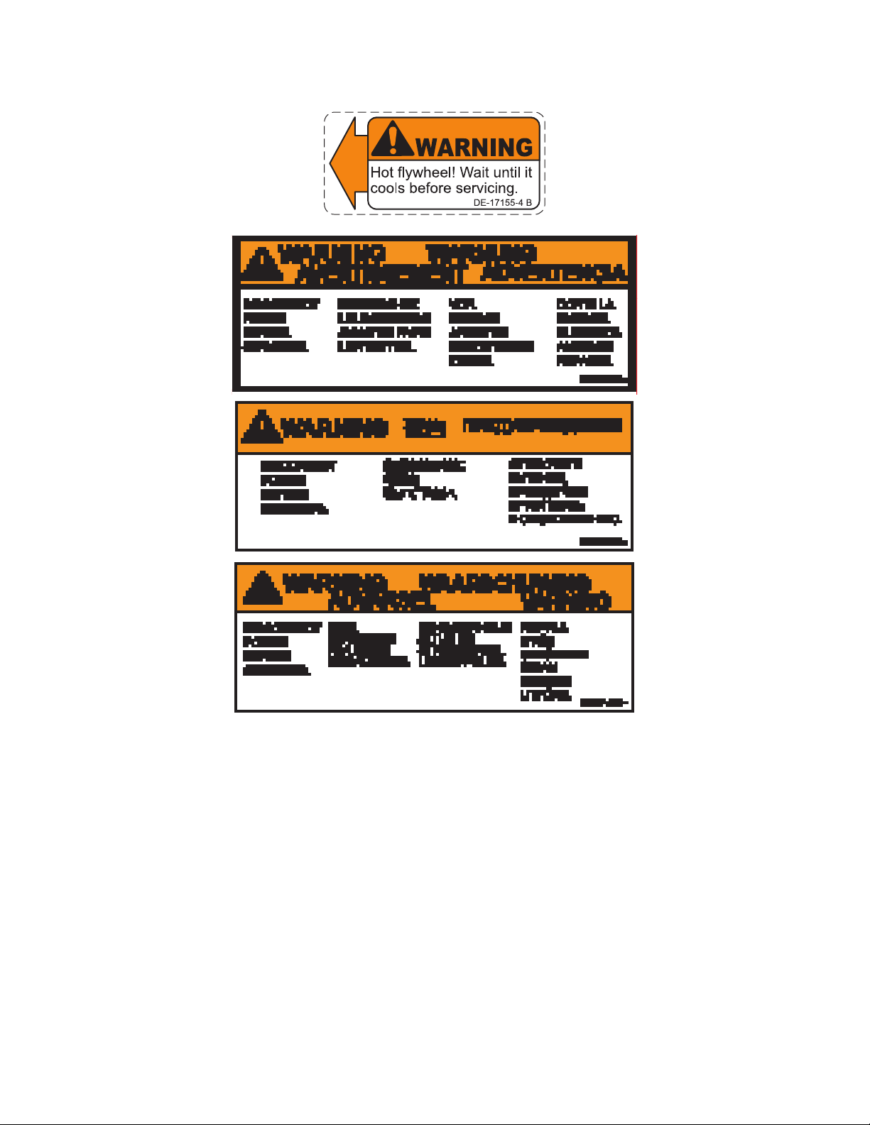
Warning and Caution Decals
To replace any worn or damaged decals do one of the following: Visit www.cybexintl.com to shop
for parts online, fax orders to 508-533-5183 or contact Cybex Customer Service at 888-462-9239. If
you are located outside of the USA, call 508-533-4300. For location or part number of labels, see the
parts list and exploded-view diagram on the Cybex web site at www.cybexintl.com.
Warning decals indicate a potentially hazardous situation which, if not avoided, could result in death
or serious injury.
Carefully read and understand the following caution and warning labels before using the unit.
Canadian
CAUTION
Moving parts.
Keep hands away
when in use.
DE-17219-4 B
Canadian
6
Page 7
7
Page 8

Cybex Service Manual
1
2
4
5
3
1 770A-331-4 Label, Warning, Access tray, Left
1 770A-331-E Label, Warning, Access tray, Left, Canadian
2 770A-332-4 Label, Warning, Access tray, Right
2 770A-332-E Label, Warning, Access tray, Right, Canadian
3 DE-18362-4 Decal, Caution moving parts
4 DE-18363-4 Label, Warning, Hot ywheel
5 525AT-400 Label, Warning, Disconnect Power
5 525AT-401 Label, Warning, Disconnect Power
5 525AT-402 Label, Warning, Disconnect Power
8
Page 9

Cybex Service Manual Cybex Service Manual
Maintenance
All preventive maintenance activities must be performed on a regular basis. Performing routine
preventive maintenance actions can aid in providing safe, trouble-free operation of all Cybex
equipment.
Cybex is not responsible for performing regular inspection and maintenance actions for your
machines. Instruct all personnel in equipment inspection and maintenance actions and also in
accident reporting/recording. Cybex representatives are available to answer any questions that you
may have.
WARNING: For maintenance, service and repair
• Should only be performed by trained personnel
• Use only Cybex replacement parts
• Unplug unit before working on it
• Keep water and liquids away from electrical parts
Warnings
Read all warnings in this chapter and in the Safety Section.
Observe the following warnings:
DANGER: Electrocution hazard
To avoid death or serious injury unplug unit when not in use or when performing
maintenance
WARNING: Equipment hazard
To avoid serious injury or death replace worn or damaged components immediately
and keep the equipment out of use until repair is completed
NOTICE: Repairs and Service
• All inspections and repairs must be performed by trained service personnel only
• Cybex requires that only Cybex replacement parts are used
9
Page 10

Cybex Service Manual
Preventive Maintenance Activities
Perform regular preventive maintenance to ensure normal operation of unit. Keep a log of all
maintenance actions to assist in staying current with all preventive maintenance activities.
Cybex is not responsible for performing regular inspection and maintenance actions for your unit.
Instruct all personnel in equipment inspection and maintenance actions and also in accident reporting/
recording. Contact Cybex Customer Service at 888-462-9239 or 508-533-4300 for any preventive
maintenance or service concerns.
Read and understand warnings listed in this chapter and in the Safety Section. Read and
understand all instructions in this section.
During maintenance, disconnect the power cord from the power outlet.
For some maintenance activities it will be necessary to remove and replace the access cover.
ToolRequired
Phillips screwdriver
Cleaning Unit
When cleaning your treadmill spray a mild cleaning agent, such as a water and dishsoap solution,
on a clean cloth rst and then wipe the treadmill with the damp cloth. Do not spray cleaning solution
directly on the treadmill. Direct spraying could cause damage to the electronics and may void the
warranty.
WARNING: Shock and electrocution hazard
• Unplug unit and let sit 10 minutes before cleaning or performing maintenance
• Electrical charge can remain in unit after unplugging
• Keep water and liquids away from electrical parts
AfterEachUse— Wipe up any liquid spills immediately. After each workout, use a cloth to wipe up
any remaining perspiration from the handrails and painted surfaces.
Be careful not to spill or get excessive moisture between the edge of the display panel and the
console, as this might create an electrical hazard or cause failure of the electronics.
AsNeeded— Vacuum any dust or dirt that might accumulate under or around the unit. Cleaning this
area should be done as often as indicated in the Service Schedule.
ContactHeartRateGrips—Contaminants, such as hand lotions, oils or body powder, may come off
on the contact heart rate grips. These can reduce sensitivity and interfere with the heart rate signal.
It is recommended that the user have clean hands when using the contact heart rate. Clean the grips
using a cloth dampened with a cleaning solution containing rubbing alcohol.
10
Page 11

Cybex Service Manual Cybex Service Manual
Remove Access Cover
1. Remove the two lower screws securing the access cover using a Phillips screwdriver.
1
Item Description
1 Upper screws
1
2
3
3
2 Access cover
3 Lower Screws (2)
2. Remove two upper screws securing the access cover using a Phillips screwdriver. Refer to the
above diagram.
3. Remove the access cover.
WARNING: Burn hazard
Do not touch ywheel until cool
11
Page 12

Cybex Service Manual
Drive Belts
There are two drive belts that may become loose, worn or cracked.
Unless the belts have been removed and not replaced properly, it is unlikely the belts will come loose
or need to be re-tensioned.
Item Description
1 Primary drive belt
2 Secondary drive belt
2
1
If a belt has cracks or appears worn, it must be replaced immediately by a qualied service
technician.
PrimaryBelt–The wider of the two belts. It has grooves that keep it aligned on the large upper
pulley.
SecondaryBelt – The narrower of the two belts. It has grooves that keep it aligned on the ywheel’s
drive pulley.
Attach Access Cover
Do not over tighten screws.
1. Replace and tighten the two upper screws removed in step 2 Remove Access Cover using a
Phillips screwdriver.
2. Replace and tighten the two lower screws removed in step 1 Remove Access Cover using a
Phillips screwdriver.
3. Plug the power cord into a power outlet.
4. Test unit for proper operation.
12
Page 13

Cybex Service Manual Cybex Service Manual
E3 View Monitor
Cleaning
1. Unplug power cord from the wall socket.
2. Dust off the panel with a soft dry cloth as needed. The screen can be cleaned with computer
screen wipes or other non-abrasive, moist, disposable wipes.
StorageorLongNon-UsePeriods
When not using product for an extended period of time the product should be disconnected from the
Power Supply, TV/Cable Signal Feed, and any Peripheral Devices.
Pixels
Very small red, blue, white or green spots may be visible or may appear on the screen. This is a
characteristic of liquid crystal display panels and is not a faulty condition. The liquid crystal panel is
built with very high precision technology giving ne picture details. Occasionally, a few non-active
pixels may appear on the screen as a xed point. This does not affect the performance of monitor or
merit a warranty claim.
Maintenance
• It is very important to have the unit regularly examined by a qualied technician to ensure the
product is t for use.
• If the unit malfunctions, please refer to a qualied technician for repair or replacement of defective
parts immediately. Do not attempt to use the monitor until it has been inspected and repaired by a
qualied technician.
• For inspection, installation and servicing, please consult qualied technician.
• Failure to use a manufacturer approved repair technician may void any warranty claims.
Recommended Service Schedule
All maintenance activities shall be performed by qualied personnel. Failure to do so could result in
serious injury.
This is the minimum recommended service.
Determinedistance
1. Verify foot plates are completely stopped.
2. Grasp handrail and step carefully onto foot plates. Begin striding.
3. Press and the hold the Displayoption and DOWN keys for 3 seconds. A beep
signies the rst screen of the Statistics menu.
4. Press the UP and DOWN keys to scroll up and down in the statistics menu.
13
Page 14

Cybex Service Manual
The Statistics menu includes: Miles/Km, Hours, Starts, and Error log.
5. The rst menu item is Miles/Km.
6. Record Distance.
7. Navigate to menu item Hours.
8. Record Hours.
9. Navigate to menu item Errorlog.
10.Record Errors.
11.Exit Statistics menu by pressing the STOP key.
First500Miles(800KM)
Follow this procedure to ensure the belts are tensioned properly and in good condition.
1. Unplug the unit from the power outlet.
2. Remove access cover. (See previous procedure Remove Access Cover)
3. Pull down and roll each belt to examine the condition. If a belt has cracks or appears worn, it
must be replaced immediately by a qualied service technician.
4. Attach access cover. (See previous procedure Attach Access Cover).
5. Plug the power cord into a power outlet.
Every5000Miles(8000KM)
Check drive belts for tension and wear. (See procedure First 500 Miles)
Move unit and vacuum underneath. Lift the rear of unit and roll it back from its present
position. Vacuum underneath and return unit to normal position.
Clean inside unit.
1. Unplug the unit from the power outlet.
2. Remove access cover. (See previous procedure Remove Access Cover)
3. Clean the exposed components using a vacuum cleaner attachment or hand vacuum.
4. Remove dirt and debris from internal components.
5. Using a dry cloth, wipe all exposed areas.
6. Attach access cover. (See procedure Attach Access Cover).
7. Plug the power cord into a power outlet.
Every20,000Miles(32000KM)
Contact qualied service technician to check elevation assembly, replace any worn parts and
lubricate elevation bushings.
14
Page 15

Cybex Service Manual
Customer Service
Product Registration
To register product do the following:
1. Visit www.cybexintl.com.
2. Locate Product Registration in the Support section.
3. Fill out form completely.
4. Click the Submit button to register product.
Contacting Service
Hours of phone service are Monday through Friday from 8:30 a.m. to 6:00 p.m. Eastern Standard
Time.
For Cybex customers living in the USA, contact Cybex Customer Service at 888-462-9239.
For Cybex customers living outside the USA, contact Cybex Customer Service at 508-533-4300 or
fax 508-533-5183. Email address internationaltechhelp@cybexintl.com
Find information on the web at www.cybexintl.com.
To contact us online go to www.cybexintl.com.
Ordering Parts
To order parts online go to www.cybexintl.com.
To speak with a customer service representative, call 888-462-9239 (for customers living within the
USA) or 508-533-4300 (for customers outside the USA).
The following information located on the serial number decal will assist our Cybex representatives in
serving you.
• Unit Serial Number, Product Name and Model Number
• Part Description and Part Number if you have it. All parts can be found on the web at
www.cybexintl.com
• Shipping Address
• Contact Name
• Include a description of the problem.
In addition to your shipping address and contact name, your account number is helpful but not
required. You may also fax orders to 508-533-5183.
15
Page 16

Cybex Service Manual
Return Material Authorization (RMA)
The Return Material Authorization (RMA) system is used when returning material for placement,
repair or credit. The system assures that returned materials are properly handled and analyzed.
Follow the following procedures carefully.
Contact your authorized Cybex dealer on all warranty-related matters. Your local Cybex dealer will
request a RMA from Cybex, if applicable. Under no circumstances will defective parts or equipment
be accepted by Cybex without proper RMA and an Automated Return Service (ARS) label.
Please contact Cybex Customer Service for the return of any item that is defective.
Provide the technician with a detailed description of the problem you are having or the defect in the
item you wish to return. Provide the model and serial number of your Cybex equipment.
At Cybex’s discretion, the technician may request that you return the problem part(s) to Cybex for
evaluation and repair or replacement. The technician will assign you a RMA number and will send
you an ARS label. The ARS label and the RMA numbers must be clearly displayed on the outside of
the package that contains the item(s) to be returned. Include the description of the problem, the serial
number of the equipment and the name and address of the owner in the package along with the
part(s).
Merchandise returned without an RMA number on the outside of the package or shipments sent COD
will not be accepted by the Cybex receiving department.
Damaged Parts
Materials damaged in shipment should not be returned for credit. Shipping damages are the
responsibility of the carrier (UPS, Federal Express, trucking companies, etc.)
Apparent Damage
Upon receipt of your shipment, check all items carefully. Any damage seen with a visual check must
be noted on the freight bill and signed by the carrier’s agent. Failure to do so will result in the carriers
refusal to honor your damage claim. The carrier will provide you with the required forms for ling such
claims.
Concealed Damage
Damage not seen with a visual check upon receipt of a shipment but notices later must be reported
to the carrier as soon as possible. Upon discovery of the damage, a written or phone request to
the carrier asking them to perform an inspection of the materials must be made within ten days of
the delivery date. Keep all shipping containers and packing materials as they will be needed in the
inspection process. The carrier will provide you with an inspection report and the necessary forms for
ling a concealed damage claim. Concealed damage claim is the carrier’s responsibility.
16 PB
Page 17
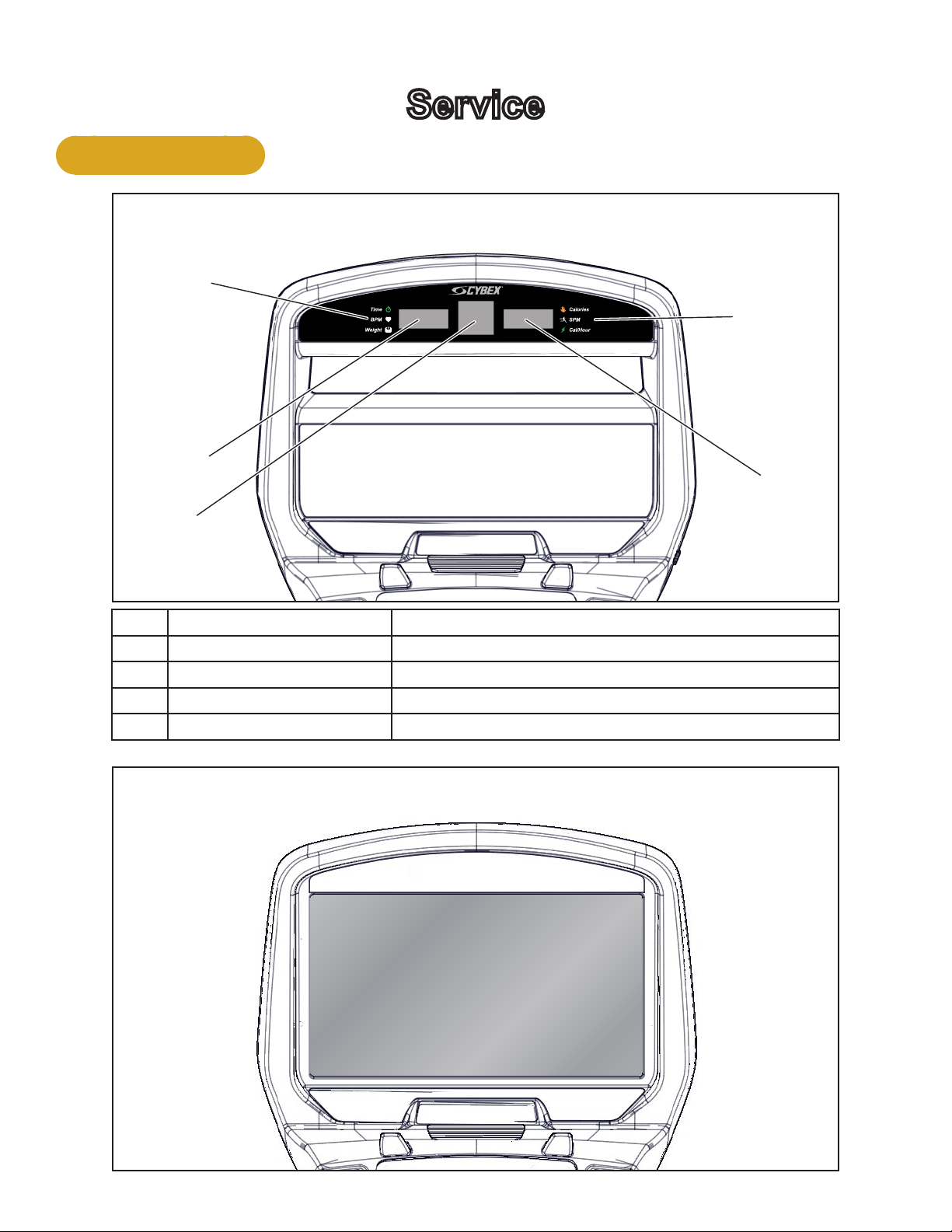
Console Display
1
2
Cybex Service Manual
Service
LED Display
4
5
3
1 Left enunciator Displays Time, BPM, or Weight.
2 Left data readout Displays value of Time, BPM, or Weight.
3 Bar graph Displays workout proles and setup options.
4 Right enunciator Displays Calories, SPM, or Cal/Hour.
5 Right data readout Displays value of Calories, SPM, or Cal/Hour.
E3 View Monitor
17
Page 18

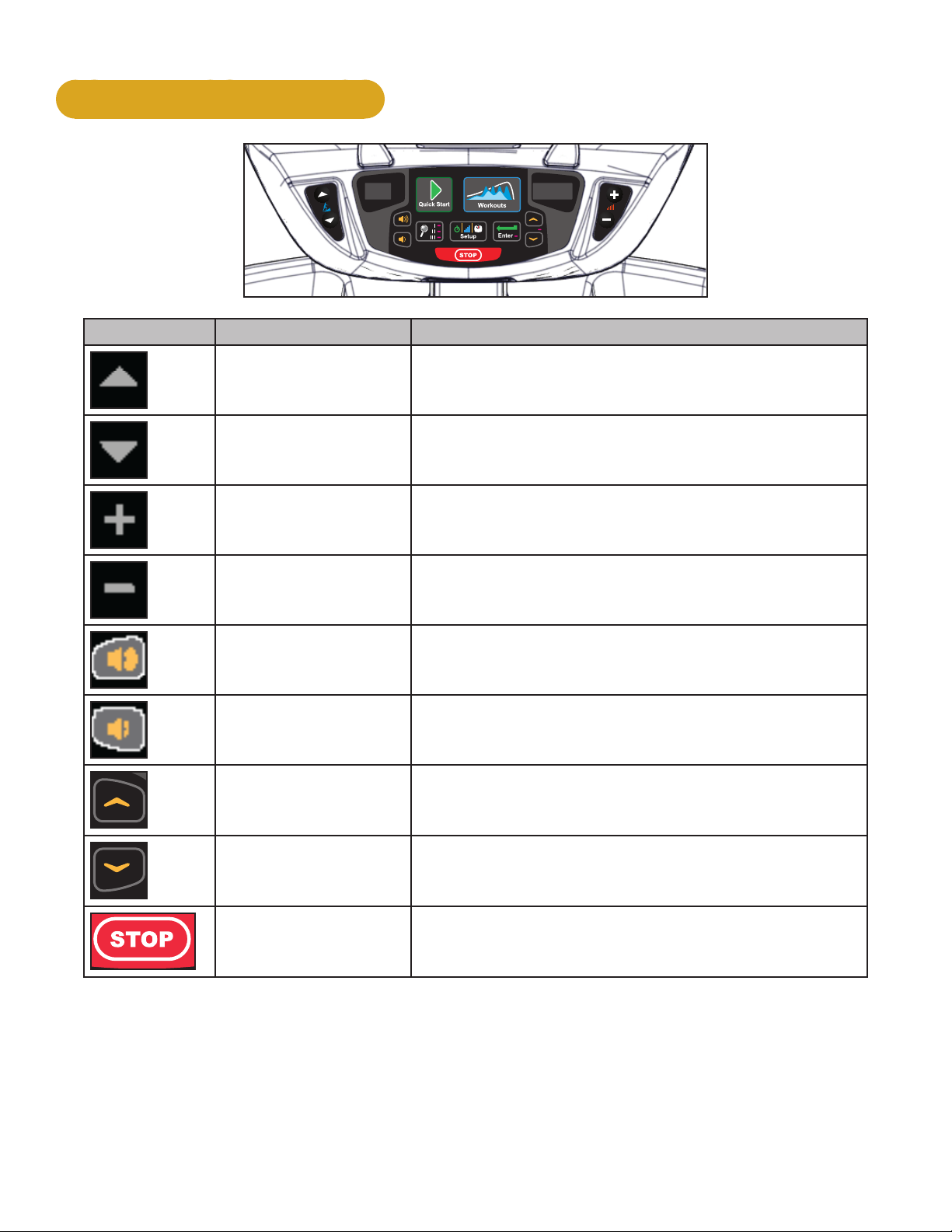
User Controls
1 2 3 4 5 6
Cybex Service Manual
8 119 10 12 137
1 Incline keys
2 Incline display
3 Quick Start key
4 Workouts key
5 Resistance display
6 Resistance keys
7 Volume keys
8 Display option key
9 Headphone jack
10 STOP key
11 Setup key
12 Enter key
13 Up/Down keys
Displays — Incline and Resistance are shown in the LED displays.
Keys — User controls for Incline, Quick Start, Workouts, Resistance, Volume, Scan, STOP, Setup,
Enter and Up/Down.
18 19
Page 19
Cybex Service Manual
User Control Symbols Used
Control Control Name Description
INCLINE UP Adjust Incline up
INCLINE DOWN Adjust Incline down
RESISTANCE UP Adjust Resistance up
RESISTANCE DOWN Adjust Resistance down
VOLUME UP Adjust Volume up
VOLUME DOWN Adjust Volume down
UP KEY
Adjust Time, Level, Weight, or Workout up
A/V - Channel UP
iPod - NEXT track (option)
DOWN KEY
Adjust Time, Level, Weight, or Workout down
A/V - Channel DOWN
iPod - PREVIOUS track (option)
STOP
Press STOP to end the workout session. If pause
feature is enabled, press STOP once to enter pause
mode.
19
Page 20

Cybex Service Manual
Setup
Use the following instructions to setup the units settings.
1. Plug the power cord into a power outlet from a grounded circuit, See Electrical
Requirements. Coil up the remainder of the power cord and place it out of the way.
2. Toggle the on/off (I/O) power switch under the front end of the unit to the on position (I). The
control panel will light up.
3. Hold the handrails to steady self while stepping into the foot plates.
4. Begin striding.
Time and Date conrmation
The rst time the unit is turned on, it prompts the user to conrm the current Time and Date. Quick
Start, Workouts, Setup or Stop will skip this requirement but it will appear again the next time the unit
is powered up until the time and date are properly set.
1. Press the ENTER key to begin editing the time, starting with the hours (HH) and then
minutes (MM) and then AM/PM/24.
2. Press the UP and DOWN keys to select the hour.
3. Press the ENTER key to accept and begin editing the minutes.
4. Press the UP and DOWN keys to select the minutes.
5. Press the ENTER key to accept and begin editing the AM/PM/24 hour setting.
6. Press the ENTER key to accept time.
Continue this procedure for the Date. Date format is [YYYY] [MM] [DD]. Y - Year, M - Month and D Day.
7. Press the ENTER key after the nal setting for Day. The opening screen will now be
displayed.
Time and Date conrmation complete.
Setup options
1. Press and the hold the Display option and UP keys for 3 seconds.
2. Navigate through the setup menu with the UP and DOWN keys.
20 21
Page 21

Cybex Service Manual
3. Press the ENTER key once to enter setup values. Press again to save any changes
and advance forward in the menu.
The Setup options are:
LED Console E3 View Monitor
Time Set time display format AM, PM, or 24. Set time in Hours and Minutes HH:MM.
Date Year format is Y - Year [YYYY]. Date format is [YYYY] [MM] [DD]. Y -
Month format is M - Month [MM].
Year, M - Month, and D - Day.
Day format is D - Day [DD].
Weight and
Distance Units
LbS - Pounds, Kg - Kilograms or
Ston - Stone.
MI - Miles or KM - Kilometers.
LBS - Pounds, Kg - Kilograms or
Stone - Stone.
MI - Miles or KM - Kilometers.
Pause Set time length for Pause. OFF (Default), 1:00, 5:00 or 10:00 minutes.
Max Time Set maximum workout time. OFF (Unlimited), 20, 30, 60 (Default), or 120
minutes.
Default Time Set default workout time. 30, 60 (Default), 90, 120 miutes, off. or club*.
Max Time Set maximum workout time. OFF (Unlimited), 20, 30, 40, 50, 60 (Default), 90 or
120 minutes.
Tone Toggle console beeper On (Default) or OFF.
Dormant Style Not available Default, Default with time (Clock
shown), Heart only or Energy Saver
(All LED’s off except for center dashes
on membrane.
A/V Set A/V option. Choices are PEM, UHF, none, or FM (TF/M). See A/V Cong
and FM Radio Presets for full conguration. If unit ships with E3 View Monitor,
this setup option is skipped.
*Club setting limits the workout time to 60 minutes during peak times. Peak times are 5:01 AM to
9:00 AM, and 4:01 PM to 9:00 PM
To reset setup options to default values
1. Press the Display option key at the rst setup option screen (Time). The console will
display “[rSEt] [? ]“.
To exit without resetting, press the STOP or ENTER key.
2. To reset setup options, press the UP and DOWN keys to select “[YES]” and press the
ENTER key.
Exit Set Up Mode.
1. Press the STOP key to exit Setup options.
21
Page 22

Cybex Service Manual
REVISIONS
DESCRIPTION
See sheet 1
ECO
REV
D A TE APPRO V AL
BY
.
.
.
GLOSS AREAS
REVISIONS
DESCRIPTION
See sheet 1
ECO
REV
D A TE APPRO V AL
BY
.
.
.
GLOSS AREAS
Service Diagnostics
Service diagnostics allows testing, monitoring or altering of unit controls and performance.
1. Press the STOP key several times.
2. Press the Display option
key and DOWN key for three seconds.
Navigation while in Statistics or Diagnostic menus:
Up/Down keys Scroll up and down in menu. Adjust data values.
Enter Enter and exit menu items, move forward in menu if not required.
STOP Exit back to Dormant Mode.
Quick Start Select Diagnostics.
Statistics menu:
S1 Miles Total distance in Miles or Kilometers.
S2 Hours Total hours of workout time.
S3 Starts Total number of workout starts.
S4 Error Log Displays number of errors, up to 20. If no errors are stored “[ 0 ] [Err ] [Log]” will
be displayed.
To scroll through error log press Enter, then use Up/Down keys.
When viewing error log use the Enter key to toggle display to Time Stored, Date
stored, then back to error number.
Reset - While viewing error log press the Display option
key twice.
Press the Quick Start key to exit error log and enter Diagnostics menu.
Press the Enter key to scroll through options.
Diagnostics menu:
T1 Test home Displays Drive software version, MCC board software version and heart rate
board version (POL - Polar or SAL - Salutron).
LED test Press Quick Start key to start. A quick LED text begins with lighting the following
for three seconds each. Bar Graph Matrix (BGM) LEDs and heart in red, center
numerics and heart in green, membrane LED’s and heart in blue.
Key test Press Workouts key to start. Test each key by pressing once. Each key press is
recognized with a beep, center numeric displays assigned number per key. Press
STOP key once to test, hold for two seconds to exit key test.
T2 Brake ID Displays which brand of brake/generator is in use. Each one has different output
T3 Load
pulses. [PAR] - Paras brand, [C-H] - Chi Hua brand.
Displays the load calibration value at 0 amps, no load.
0 amps
T4 Load
Displays the load calibration value at 1 amp.
1 amp
22 23
Page 23

Cybex Service Manual
REVISIONS
DESCRIPTION
See sheet 1
ECO
REV
D A TE APPRO V AL
BY
.
.
.
GLOSS AREAS
Press the STOP key to return to Dormant Mode. If drive motor was running press the STOP key
again.
Error Codes
Error codes notify user of a problem condition and are displayed on the console. Error codes can also
help to indicate the part of the unit most likely to be causing the problem.
1. Press the STOP key several times.
2. Press the Display option
key, and Speed Down key for three seconds.
3. Press the Up/Down keys until Error Log is displayed. Total number of errors will be displayed.
If three dashes “- - -” are shown, the error log is empty.
4. Press ENTER and use the Up/Down keys to scroll through the error log.
Error Code Listing
Error Code # Meaning
2 GFX Communications issue
4 Upper Display comm. issue
5 Drive comm. issue
6 Membrane fault
8 Approaching Over-Temp
9 MCC Watchdog Triggered
12 Graphics board watchdog
13 Upper display watchdog
14 Drive error unknown
15 Embedded A/V Device failure
16 Membrane fault
18 LCB 12v out of range
19 LCB 3.3v or 50v out of range
29 Controller watchdog tripped
45 AC Incline timeout UP
46 AC Incline timeout DOWN
23
Page 24

Cybex Service Manual
REVISIONS
DESCRIPTION
See sheet 1
ECO
REV
D A TE APPRO V AL
BY
.
.
.
GLOSS AREAS
When viewing error log use the ENTER key to toggle display to Time Stored, Date stored, then
back to error number. To reset the error log press the Display option
5. Exit Statistics menu by pressing the STOP key to return to Dormant Mode.
See Appendix A for error code owcharts.
key twice.
24 25
Page 25

Cybex Service Manual
Linkage Rods and Foot Plates
In this section you have the option to remove and install the following parts:
• Linkage rod
• Arm handle linkage
• Foot plate assembly
• Front foot plate arm
• Rear foot plate arm
Linkage Rod
Tools Required
• 3/16” Allen wrench
• 7/32” Allen wrench
• Phillips screwdriver
• Rubber mallet
• Torque wrench
• Loctite
Remove linkage rod (Procedure shows right side)
1. Remove SHCS, at washer, cap and spacer from both ends of linkage rod using a 3/16” Allen
wrench.
3
2
4
5
Description
1 Lingake rod
2 SCHS
3 Flat washer
4 Cap
5 Spacer
1
2
2. Remove linkage rod.
5
4
3
25
Page 26

Cybex Service Manual
Arm Handle Linkage
Remove Arm Handle Linkage
1. Remove SHCS, at washer, cap, and spacer securing arm handle linkage using a 3/16” Allen
wrench.
1
2
7
6
2. Remove arm handle linkage from handle.
3
4
5
Description
1 Arm handle linkage
2 Spacer
3 Cap
4 Flat washer
5 SHCS
6 Hole (not shown)
7 Handle
Foot Plate Assembly
Remove Foot Plate Assembly
1. Remove both SHCS and washers securing foot plate using a 3/16” Allen wrench.
1
5
3
4
2
Description
1 Rear foot plate shaft
2 SHCS
3 Washer
4 Foot plate
5 Front foot plate shaft
2. Remove foot plate from front and rear foot plate shafts.
26 27
Page 27

Cybex Service Manual
Front Foot Plate Arm
Remove Front Foot Plate Arm
1. Remove BHSCS, cap, and spacer securing front foot plate arm using a 7/32” Allen wrench.
1
2. Remove front foot plate arm using a rubber mallet.
2
3
4
Description
1 Front foot plate arm
2 Spacer
3 Cap
4 BHSCS
Rear Foot Plate Arm
Remove Rear Foot Plate Arm
1. Remove BHSCS, cap, and spacer securing rear foot plate arm using a 7/32” Allen wrench.
3
2
1
4
Description
1 Front foot plate arm
2 Spacer
3 Cap
4 BHSCS
2. Remove rear foot plate arm using a rubber mallet.
27
Page 28

Install Rear Foot Plate Arm
1. Position new rear foot plate arm in place.
Cybex Service Manual
3
4
2
Description
1 Front foot plate arm
2 Spacer
1
5
3 Cap
4 BHSCS
5 Loctite
2. Place a drop of Loctite on the BHSCS and another drop inside the shaft into where the BHSCS
will be tightened.
3. Install BHSCS, cap, and spacer to rear foot plate arm using a 7/32” Allen wrench. BHSCS must
be tightened to a minimum of 250 lbs-in.
Install Front Foot Plate Arm
1. Position front foot plate arm in place.
1
2
3
4
Description
1 Front foot plate arm
2 Spacer
3 Cap
5
4 BHSCS
5 Loctite
2. Place a drop of Loctite on the BHSCS and another drop inside the shaft into where the BHSCS
will be tightened.
3. Install BHSCS, cap, and spacer to front foot plate arm using a 7/32” Allen wrench. BHSCS
must be tightened to a minimum of 250 lbs-in.
28 29
Page 29

Install Foot Plate Assembly
1. Slide foot plate onto the foot plate shafts.
Cybex Service Manual
1
2
Description
1 Rear foot plate shaft
2 Loctite
3 SHCS
4 Washer
6
5
4
3
5 Foot plate
6 Front foot plate shaft
2. Place a drop of loctite on each SHCS. Place another drop of loctite in each shaft (where the
SHCS will be tightened into).
3. Install both washers and both SHSC using a 3/16” Allen wrench.
Install Arm Handle Linkage
1. Install arm handle linkage to handle.
1
2
3
4
7
Description
1 Arm handle linkage
2 Spacer
3 Cap
4 Flat washer
6
5
5 SHCS
6 Hole (not shown)
7 Handle
2. Place a drop of loctite on SHCS. Place another drop of loctite into the threads of the shaft.
3. Install SHCS, at washer, cap, and spacer securing the arm handle linkage using a 3/16” Allen
wrench. SHCS must be tightened to a minimum of 90 lbs-in.
29
Page 30

Install Linkage Rod
1. Place linkage rod in correct position.
Cybex Service Manual
3
2
4
Description
1 Lingake rod
6
2 SCHS
5
3 Flat washer
4 Cap
5 Spacer
6 Loctite
5
1
2
3
4
2. Place a drop of loctite on the SHCS and place another drop of loctite into the shaft (where the
SHCS will be tightened into).
3. Install spacers, caps, at washers, SHCS. SHCS must be tightened to a minimum of 90 lbs-in.
Complete installation
Operate the unit at all levels to verify proper operation.
Arm Handle
Tools Required
• 3/16” Allen wrench
• 7/32” Allen wrench (2)
• Torque wrench
Remove heart rate cable
Unplug heart rate cable from socket in frame.
1
2
Description
1 Socket in frame
2 Heart rate cable
30 31
Page 31

Cybex Service Manual
Remove linkage arm
Remove SHCS, at washer, cap, and spacer securing linkage arm to arm handle using a 3/16” Allen
wrench.
Description
6
5
1
1 Arm handle
2 Linkage arm
2
3 Spacer
4 Flat washer
4
3
5 SHCS
6 Cap
Remove arm handle
1. Remove BHSCS, washer, and pivot pin securing arm handle using two 7/32” Allen wrenches.
The BHSCS and washer from only one side needs to be removed.
6
1
Description
1 Arm handle
2
2 Pivot pin
3 BHSCS
4 Washer
5
4
3
4
5 BHSCS
6 Loctite
2. Remove arm handle.
Install new arm handle
1. Place new arm handle in position and slide pivot pin back in place.
2. Apply loctite to threads of BHSCS and inside the pivot pin (where BHSCS will be tightened
into).
3. Install BHSCS and washer to pivot pin. Tighten BHSCS using two 7/32” Allen wrenches
securely. When tightened properly, frame tabs are pulled tight to the bearing.
31
Page 32

Cybex Service Manual
Install linkage arm
1. Place a drop of loctite on the SHCS and another drop in shaft where the SHCS will be
tightened into.
1
2
3
7
Description
1 Loctite
2 Cap
3 Arm handle
4
4 Linkage arm
6
5
5 Spacer
6 Flat washer
7 SHCS
2. Install linkage arm, spacer, cap, at washer, and SHCS to arm handle.
3. Tighen SHCS securely. SHCS must be tightened to a minimum of 90 lbs-in.
Install heart rate cable
Plug heart rate cable into connector in frame.
Description
1 Socket in frame
2 Heart rate cable
1
2
Complete installation
1. Operate the unit at all levels to verify proper operation.
2. Hold the hand grips on the console handrail until a heart rate is displayed, typically less than
thirty seconds.
32 33
Page 33

Cybex Service Manual
Pulley and Crank Shaft Assembly
In this section you have the option to remove and install the following parts:
• Crank covers
• Shrouds
• Control board
• Crank arms
• Crank shaft assembly
• Counterweights
Tools Required
• 3/16” Allen wrench
• 7/32” Allen wrench
• 7/16” Socket wrench
• 1/2” Socket wrench
• 9/16” Socket wrench
• 7/32” Hex bit socket
• 3” Socket wrench extension
• Cloth or rag (2)
• 9/16” Open end wrench
• Torque wrench
• Phillips screwdriver
• Long Phillips screwdriver
• Hammer
A cordless drill with a long Phillips bit is recommended but not required.
Elevate unit and disconnect power
1. Press the incline UP key to level 20 incline.
WARNING: Shock and electrocution hazard
• Unplug unit and let sit 10 minutes before cleaning or performing maintenance
• Electrical charge can remain in unit after unplugging
• Keep water and liquids away from electrical parts
• Lower pivot assembly
2. Unplug the power cord from power outlet.
Remove linkage rods
1. Remove the socket head cap screw (SHCS), at washer, cap and spacer securing the linkage
rod using a 3/16” Allen wrench.
2
3
1
4
5
Description
1 Spacer
2 SHCS
3 Flat washer
4 Cap
5 Linkage rod
2. Lay the linkage rod down on the frame. Place a cloth in between the linkage rod and the frame
to prevent scratches.
3. Repeat steps 1 and 2 for other linkage rod.
33
Page 34

Cybex Service Manual
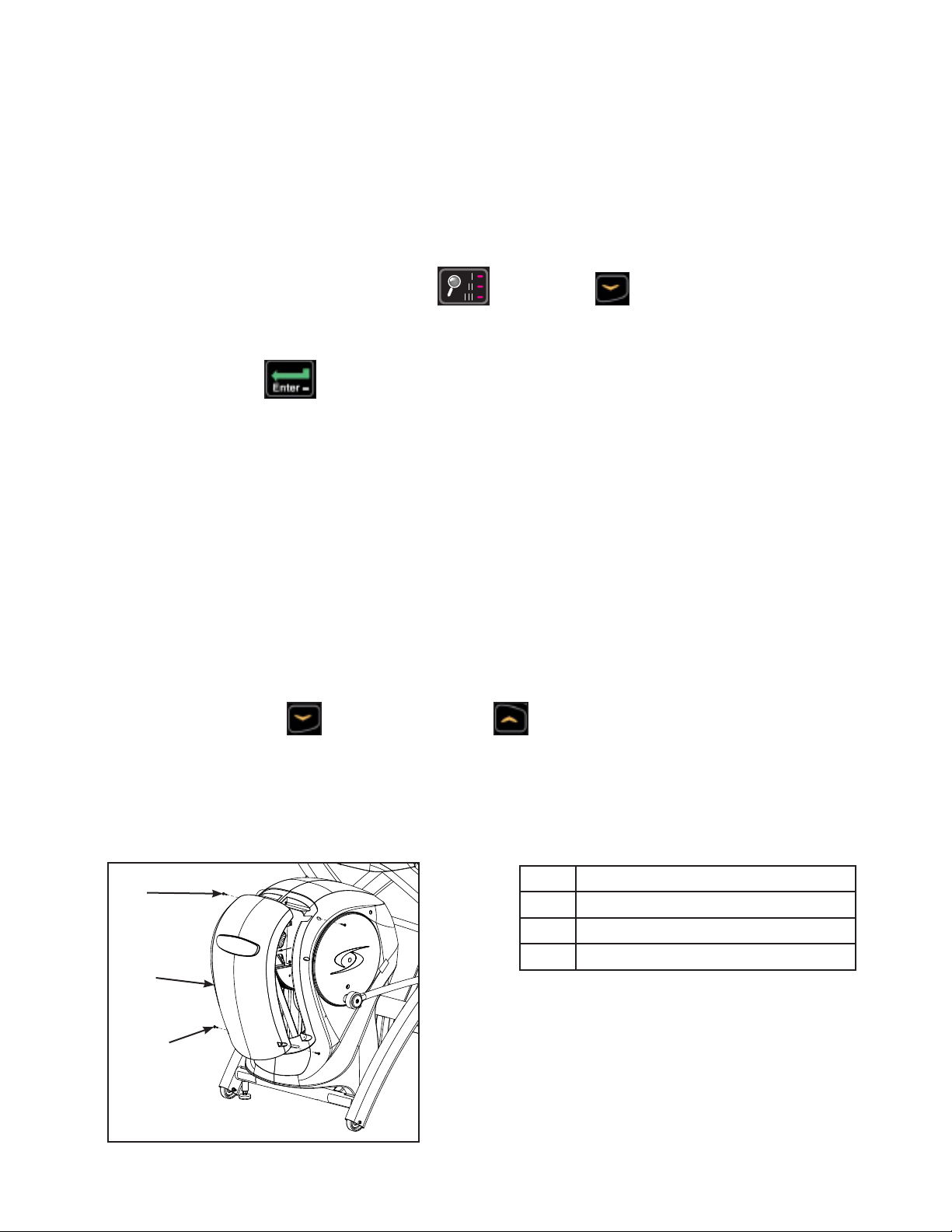
Crank Covers
Remove crank covers
1. Remove both screws securing crank cover using a Phillips screwdriver.
5
4
1
3
2
2. Remove crank cover.
Inspect crank arm mounting. Crank arm should be ush with crank shaft. Adjust with 7/16” or 1/2”
socket wrench if needed.
Description
1 Crank cover
2 Screws (2)
3 Crank arm
4 Crank Shaft
5 Flush mount
Shrouds
Remove both shrouds
1. Remove screws securing each shroud in place using a long Phillips screwdriver.
2. Remove both shrouds.
Release drive belt tension
Using a 7/16” or 1/2” socket wrench, loosen the two Hex Head Cap Screws (HHCS). Alternate a few
turns to each HHCS until they bottom out (DO NOT REMOVE).
1
3
2
Description
1 HHCS
2 Lower pivot shaft
3 Drive belts
34 35
Page 35

Cybex Service Manual
Control Board
Remove control board assembly
1. Disconnect lower cables from control board.
2. Remove screws securing control board in place using a Phillips screwdriver.
3. Suspend control board by upper cables.
Crank Arms
Remove crank arms
1. Loosen but do not remove HHCS on each crank arm using a 9/16” socket wrench.
Description
1
9
8
7
6
2
3
4
5
1 Pillow block
2 Nut (4)
3 Alignment pin
4 Flat washer (8)
5 Crank arm (2)
6 HHCS torque to 30 lbs-ft minimum
7 Primary belt
8 Bolt (4)
9 Pulley and crank shaft assembly
2. Remove crank arms.
Crank Shaft Assembly
Remove crank shaft assembly
1. Remove the four bolts, eight at washers and four nuts securing crank shaft assembly to frame
using a 9/16” socket wrench and a 9/16” open end wrench.
2. Remove crank shaft assembly.
35
Page 36

Cybex Service Manual
Counterweights
Remove counter weights
Remove at head socket cap screw (FHSCS) from both counter weights using a 7/32” Allen wrench.
1
2
3
4
5
Description
1 FHSCS (2) torque to 250 lbs-in
2 Counter weight (2)
3 Loctite (2)
4 Pulley and crank shaft assembly
5 Top edge of counter weight
needs to be perpendicular to
slot on crank shaft
Lower Pivot Assembly
Remove lower pivot assembly
1. Remove the two screws, two lock washers and two at washers from the lower pivot shaft
using a 7/16” or 1/2” socket wrench.
1
2
3
4
5
2. Remove the lower pivot assembly out of the drive belts and from the frame.
Installing lower pivot assembly
1. Slide the lower pivot assembly through both drive belts and into place on the frame. Conrm
that both drive belts are straight and centered in place.
2. Tighten one HHCS a few turns then tighten the other HHCS a few turns using a 7/16” or 1/2”
socket wrench. Alternate until both HHCS are secure.
Description
1 Screw
2 Lock washer
3 Flat washer
4 Lower pivot shaft
5 Drive belts
36 37
Page 37

Cybex Service Manual
3. Verify that both pulleys are aligned properly using a straight edge. The straight edge must be
no more than 1/16” from pulley edge.
1
Description
1 Pulley
8
2
2 The straight edge must be no
more than 1/16” from pulley
edge
3 Touch straight edge here (two
places)
4 Pulley
5 Speed sensor
7
3
4
6 Straight edge
7 The straight edge must be no
more than 1/16” from pulley
edge
6
5
8 Touch straight edge here
Install counter weights
1. Apply loctite to threads of FHSCS and inside the counter weight hole (where the FHSCS will
be tightened into).
Description
1
2
1 FHSCS (2) torque to 250 lbs in
2 Counter weight (2)
3 Loctite (2)
4 Pulley and crank shaft assembly
5 Top edge of counter weight needs
3
to be perpendicular to slot on
crank shaft
4
5
2. Attach both counter weights to new pulley and crank shaft assembly and attach FHSCS. Top
edge of counter weight needs to be perpendicular to slot on crank shaft.
3. Securely tighten the two FHSCS using a 7/32” Allen wrench. FHSCS to be torqued to
250 lbs-in.
Install crank shaft assembly
The new bearings have been pre-assembled on the new crank shaft assembly and are not
adjustable.
37
Page 38

Cybex Service Manual
1. Place the assembly into the primary belt and slide the alignment pins into the holes on the
frame. You may need to tap the pins in with a hammer so they are ush with the top of the
pillow blocks.
Description
1
2
9
3
4
1 Pillow block
2 Nut (4)
3 Alignment pin
4 Flat washer (8)
5 Crank arm (2)
6 HHCS torque to 30 lbs-ft minimum
7 Primary belt
8
5
8 Bolt (4)
9 Pulley and crank shaft assembly
7
6
2. Secure the two bolts, four at washers and two nuts to each pillow block using a 9/16” socket
wrench and a 9/16” open end wrench.
Install lower pivot shaft
Tighten one HHCS a few turns then tighten the other HHCS a few turns using a 7/16” or 1/2” socket
wrench. Alternate until both HHCS are secure.
Alignment of belts and pulleys
Verify that both pulleys are aligned properly using a straight edge. The straight edge must be no more
than 1/16” from pulley edge.
1
Description
1 Pulley
7
2
2 The straight edge must be no more
than 1/16” from pulley edge.
3 Touch straight edge here (two
places)
4 Pulley
5 Straight edge
6
3
6 The straight edge must be no more
than 1/16” from pulley edge
7 Touch straight edge here (two
places)
4
5
38 39
Page 39

Cybex Service Manual
Install crank arms
1. Slide each crank arm in place. The face of each crank arm should be ush with the end of
each shaft.
Description
1
2
9
3
4
1 Pillow block
2 Nut (4)
3 Alignment pin
4 Flat washer (8)
5 Crank arm (2)
6 HHCS torque to 30 lbs-ft minimum
7 Primary belt
8
5
8 Bolt (4)
9 Pulley and crank shaft assembly
7
6
2. Tighten HHCS on each crank arm using a 9/16” socket wrench. HHCS must to be torqued to a
minimum of 30 lbs-ft, otherwise there may be to much movement of crank arms or foot plates
during operation.
Install control board assembly
1. Place control board assembly in position on frame. If control board assembly rubs on crank
shaft, standoffs and screws will be needed.
2. Attach the screws securing the control board assembly in place using a Phillips screwdriver.
3. Connect lower cables into control board. Do not connect battery to control board at this time.
Release the tension of the primary drive belt (if applicable)
1. Loosen the bottom screw on the idler pulley using a 1/2” socket wrench.
2. Loosen the top screw on the idler pulley using a 1/2” socket wrench.
Torque the primary belt (if applicable)
1. Pull up until the idler wheel rocks against the brake and is torqued to 75 lbs-ft using a
3/8” square-hole torque wrench. Continue holding torque wrench at 75 lbs-ft during the next
step.
2. While holding the torque wrench at 75 lbs-ft, use a 1/2” socket wrench to tighten the top screw
on the idler pulley.
3. Tighten the bottom screw on the idler pulley using a 1/2” socket wrench.
39
Page 40

Cybex Service Manual
Install both shrouds
1. Place both shrouds in position.
2. Tighten the screws securing each side cover using a long Phillips screwdriver.
Install crank covers
1. Place each crank cover in position.
5
Description
1 Crank cover
4
2 Screws (2)
1
3 Crank arm
4 Crank shaft
5 Flush mount
3
2
2. Place loctite on the screws securing crank covers.
3. Install the screws securing each crank cover in place using a Phillips screwdriver.
Install linkage rods
1. Place linkage rod in correct position.
5
1
4
2
3
Description
1 Flat washer
2 Cap
3 Linkage rod
4 Spacer
5 SHCS
2. Place a drop of loctite on the SHCS and place another drop of loctite into the shaft (where the
SHCS will be tightened into).
3. Install spacers, caps, at washers, SHCS. SHCS must be tightened to a minimum of 90 lbs-in.
Test unit for proper operation
1. Plug the power cord into the power outlet.
2. Operate the unit at all levels to verify proper operation.
40 41
Page 41

Incline Motor
Tools Required
Cybex Service Manual
• Side cutter
• Phillips screwdrivers (Long
Shaft)
• Flat head screwdriver
• 1/2” ID External retaining-ring
tool
• 3/16” Allen wrench
• Torque wrench
• Cloth
Disconnect power
WARNING: Shock and electrocution hazard
• Unplug unit and let sit 10 minutes before cleaning or performing maintenance
• Electrical charge can remain in unit after unplugging
• Keep water and liquids away from electrical parts
Unplug the power cord from power outlet.
Remove incline motor cover
1. Remove both screws securing the incline motor cover using a Phillips screwdriver.
1
Description
1 Incline motor cover
2 Screw (2)
2
2. Remove incline motor cover.
Remove lower incline motor support pin and retaining ring
1. Remove retaining ring from grooved pin using a at head screwdriver.
Description
1
3
1 Incline motor
2 Retaining ring
3 Grooved pin
2
2. Remove grooved pin securing incline motor to main frame.
41
Page 42

Cybex Service Manual
Tilt front end assembly forward
Tilt front end assembly forward carefully until it stops.
Tilt
Forward
Remove front access cover
1. Remove both lower and upper screws securing front access cover using a Phillips screwdriver.
Description
1
1 Upper screw (2)
2 Front access cover
3 Lower screw (2)
2
3
2. Remove the front access cover.
Remove left linkage rod
1. Remove SHCS, at washer, cap and spacer securing linkage rod using a 3/16” Allen wrench.
2
3
1
4
5
Description
1 Spacer
2 SHCS
3 Flat washer
4 Cap
5 Linkage rod
2. Place linkage rod down on frame. Place a cloth in between linkage rod and frame to prevent
scratches.
42 43
Page 43

Cybex Service Manual
Remove left shroud
1. Remove the eight screws securing left shroud using a Phillips screwdriver.
Description
1 Screws (8)
2 Left shroud
1
2
2. Remove left shroud.
Unplug incline motor cable
1. Loosen the top two screws and remove the bottom two screws using a phillips screwdriver.
6
1
Description
1 Top screws
2
2 Incline motor cable
3 Controller cover
4 Bottom screws
3
5 Control board
6 Cable tie
5
4
2. Remove the controller cover.
3. Unplug incline motor cable from control board.
4. Cut wire tie using side cutters.
43
Page 44

Cybex Service Manual
Remove incline motor
1. Remove retaining ring from grooved pin using a at head screwdriver.
1
Description
1 Retaining ring
2
2 Groved pin
3 Incline motor
3
2. Remove grooved pin securing incline motor to main frame.
3. Remove incline motor.
Install new incline motor
1. Place new incline motor in position. Verify center of holes is equal to 10.50” (27 cm).
10.50”
(27cm)
2. Install a retaining ring to one side of grooved pin using a 1/2” ID external retaining-ring tool or
plier.
Description
1
2
1 Retaining ring
2 Grooved pin
3 Incline motor
3
3. Install grooved pin securing the new incline motor to drive frame assembly.
4. Install a retaining ring to other side of grooved pin using a 1/2” ID external retaining-ring tool or
plier.
44 45
Page 45

Cybex Service Manual
Plug the new incline motor cable into control board.
6
1
Description
1 Top screws
2
2 Incline motor cable
3 Controller cover
4 Bottom screws
3
5 Control board
6 Cable tie
5
4
5. Install wire tie securing the new incline motor cable to frame. Remove excess wire tie with side
cutters.
6. Install controller cover and both lower screws to frame using a Phillips screwdriver.
7. Tighen all four screws securing the contoller cover using a Phillips screwdriver.
Install left shroud
Using a long Phillips screwdriver, install the eight screws securing left shroud in place.
Description
1 Screws (8)
2 Left shroud
1
2
Install lower incline motor support pin.
1. Carefully tilt front end assembly backward until holes in incline motor align with the holes in the
support bracket on main frame.
45
Page 46

Cybex Service Manual
2. Attach a retaining ring to one side of grooved pin using a 1/2” ID external retaining-ring tool or
plier.
2
Description
1 Grooved pin
1
2 Incline motor
3 Retaining ring
3
3. Install the grooved pin securing the new incline motor to the main frame assembly.
4. Attach a retaining ring to the other side of grooved pin using a 1/2” ID external retaining-ring
tool or plier.
Install new incline motor cover.
Install the new incline motor cover to main frame with two screws using a Phillips screwdriver.
1
Description
1 Incline motor cover
2 Screw (2)
2
Install linkage rod
1. Install linkage rod on crank arm.
2
Description
3
1
4
5
1 Spacer
2 SHCS
3 Flat washer
4 Cap
5 Linkage rod
2. Place a drop of loctite on the SHCS and place another drop of loctite into the threads of the
shaft.
3. Install SHCS, at washer, cap and spacer using a Phillips screwdriver. SHCS must be
tightened to a minimum of 90 lbs-in.
46 47
Page 47
Cybex Service Manual
REVISIONS
DESCRIPTION
See sheet 1
ECO
REV
D A TE APPRO V AL
BY
.
.
.
GLOSS AREAS
Connect power cord
Plug the power cord into the power outlet.
Perform calibration procedure
1. Hold the handrails to steady self while stepping into the foot plates.
2. Begin striding.
3. Press and the hold the Display option
and DOWN keys for 3 seconds.
4. Press QUICK START.
5. Press the ENTER key three times until “Pivot” is displayed.
6. Stop striding. Wait until foot plates come to a complete stop before dismounting unit. Hold
handrails to steady self while stepping off unit.
7. Press QUICK START to perform calibration. The incline motor will incline to it’s maximum
extension. Stay off footplates until calibration is complete. Incline should be at 20%
(maximum).
8. Press STOP to exit.
9. Hold the handrails to steady self while stepping into the foot plates.
10. Begin striding.
11. Press QUICK START to enter Active Mode.
12. Press incline DOWN and then incline UP to reset inline to 6%.
13. Press STOP to exit. Skip to Install front access cover.
Install front access cover
1. Place front access cover in place.
1
2
3
47
Description
1 Upper screw (2)
2 Front access cover
3 Lower screw (2)
Page 48

Cybex Service Manual
2. Install the upper and lower screws using a Phillips screwdriver. Do not over tighten screws.
Test unit for proper operation
1. Plug the power cord into the power outlet.
2. Operate the unit at all levels to verify proper operation.
Accessory Tray
Tools Required
Phillips screwdriver (regular and stubby)
Remove accessory tray bottom
1. Remove the three screws securing the accessory tray bottom to the accessory tray base using
a Phillips screwdriver.
1
4
3
2. Remove the accessory tray bottom
Description
2
1 Accessory tray bottom
2 Accessory tray base
3 Screw
4 Screws (2)
48 49
Page 49

Cybex Service Manual
Remove accessory tray top
Remove the two screws securing the accessory tray top to the accessory tray bottom using a stubby
Phillips screwdriver.
Description
1
1 Accessory tray top
2 Screws (2)
2
Remove accessory tray base
Remove the four screws securing the accessory tray base to the frame using a stubby Phillips
screwdriver.
Description
1
1 Accessory tray base
2 Frame
3 Screws (4)
2
3
49
Page 50

Cybex Service Manual
Install accessory tray base
1. Place the accessory tray in position on the frame and route the optional iPod cable towards the
back of the unit. Do not pinch optional coax cable.
1
Description
1 Accessory tray base
2 Coax cable (optional)
5
3 Frame
4 Screws (4) HT592526
5 iPod cable (optional)
2
3
4
2. Install the four screws using a stubby Phillips screwdriver.
Install accessory tray top
1. Place the accessory tray top in position on the accessory tray base and route the optional iPod
cable through the notch in the accessory tray. Place the iPod cable strain relief on the inside
edge of the notch in the accessory tray.
1
6
2
3
5
4
2. Install the two screws using a stubby Phillips screwdriver.
Description
1 Strain relief
2 iPod cable
3 Accessory tray base
4 Notch
5 Screws (2) HT552512
6 Accessory tray top
50 51
Page 51

Cybex Service Manual
Install accessory tray bottom
1. Install the accessory tray bottom to the accessory tray base with three screws using a Phillips
screwdriver.
Description
4
1
1 Accessory tray base
2 Screw (1) HT552512
3 Screws (2) HT532512
4 Accessory tray bottom
3
2
Complete installation
Operate the unit at all levels to verify proper operation.
51
Page 52

Cybex Service Manual
Upper Electronics
Contact Heart Rate Grips
Tools Required
• Phillips screwdriver
• Rubber Hammer
• Wire Cutter
• Tape
• Strain relief plier or needle nose plier
Remove grips
1. Remove the ve screws securing back grip to front grip using a Phillips screwdriver.
Description
1
2
5
1 Back grip
2 Front grip
3 White (or red) heart rate wire must be on
inside (palm side
4 Black heart rate wire (shield wire) must
be on outside (nger side).
5 Screws (5)
3
4
2. Disconnect the heart rate wire from each grip.
Remove old cable and install new cable
1. Unplug heart rate cable jack (located near bottom end of arm).
3
1
2
2. Cut off the cable jack using wire cutters,.
Description
1 Remove strain relief
2 Heart rate cable
3 Unplug heart rate cable jack
3. Remove strain relief using strain relief plier or needle nose pliers.
52 53
Page 53

Cybex Service Manual
WHITE OR RED
SHIELD OR BLACK
4. Tape the heart rate cable connectors of the new cable to the cut end of the old cable. Verify
connection is secure.
5. Pull the old cable through bottom of handle until end of the new cable is up to the top of handle
opening.
6. Position the strain relief plug on heart rate cable 4” from connector.
All coils must be contained
within this area.
(4.0)
7. Install the strain relief plug into hole on handle using a strain relief plier or needle nose pliers
and a rubber hammer. Do not to damage the heart rate wire. Verify strain relief plug is secure.
Description
3
1 Secure strain relief plug into handle
2 Heart rate cable
3 Plug in heart rate cable jack
1
2
8. Plug in the heart rate cable jack.
Install grips
1. Pull the black heart rate wire through the second lowest back hole.
Description
5
1
1 Front grip
2 White (or red) heart rate wire must be
on front side
3 Black heart rate wire must be on back
4
side
4 Screws (5)
5 Back grip
2
3
53
Page 54

Cybex Service Manual
2. Pull the white (or red) heart rate wire through the second lowest front hole.
3. Connect the white (or red) heart rate wire to the tab on the front grip.
4. Connect the black heart rate wire to the tab on the back grip.
Do not pinch heart wires or allow contacts to touch each other when installing grips.
5. Install the ve screws securing back grip to front grip using a Phillips screwdriver. Do not over
tighten grips.
Complete installation
1. Operate the unit at all levels to verify proper operation.
2. Hold the contact heart rate grips until a heart rate is displayed, typically less than thirty
seconds.
LED Display Board
Tools Required
• Phillips screwdriver
• ESD (Electrostatic Discharge) grounding strap.
Disconnect power source
1. Turn the main power switch to the off (O) position.
2. Unplug the power cord from the power outlet.
WARNING: Shock and electrocution hazard
• Unplug unit and let sit 10 minutes before cleaning or performing maintenance
• Electrical charge can remain in unit after unplugging
• Keep water and liquids away from electrical parts
NOTICE: Component damage
Wear an ESD grounding strap during this procedure. Connect ESD grounding strap to
frame bolts or unpainted metal of frame. If ESD grounding strap is not available, touch
frame bolts or unpainted metal of frame before handling any electronics.
54 55
Page 55

Cybex Service Manual
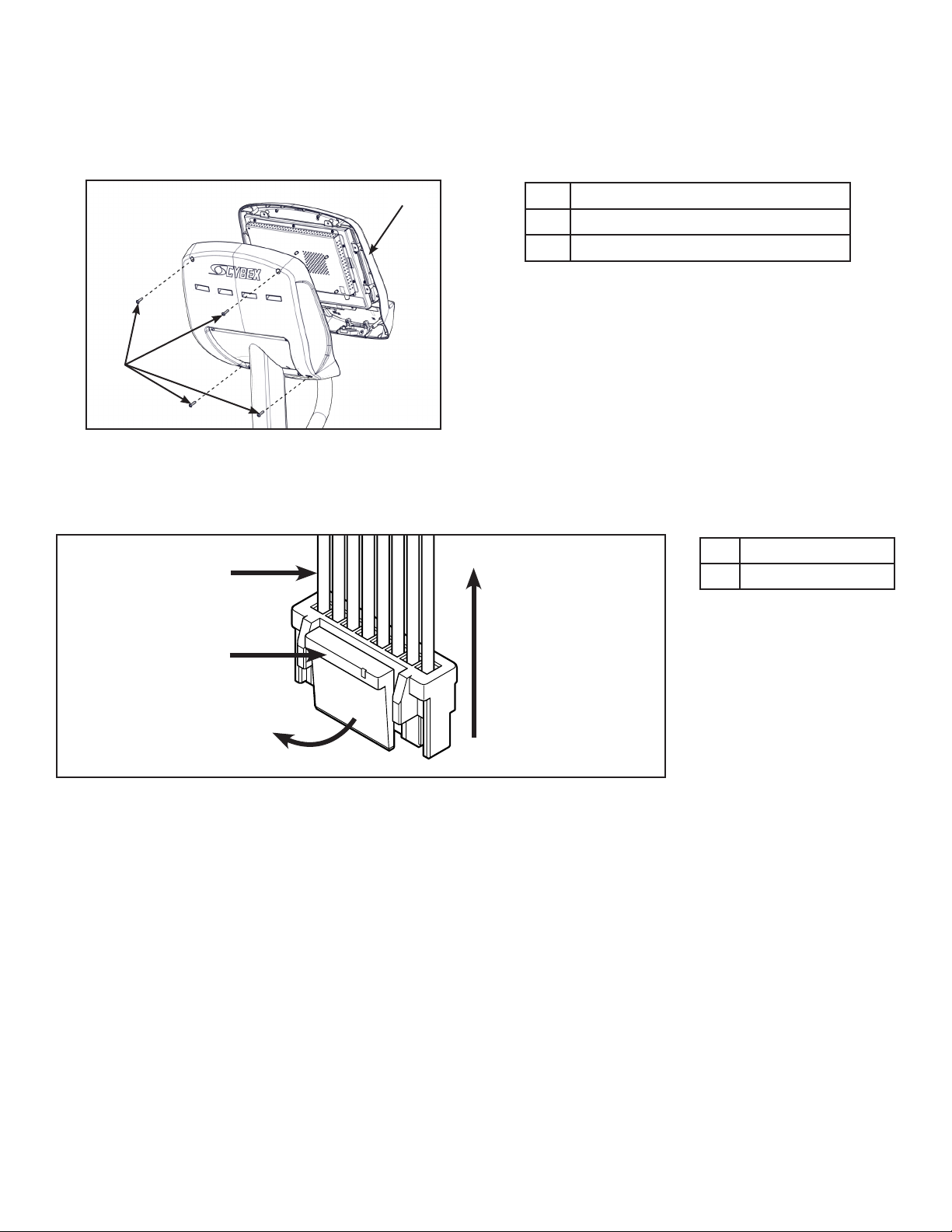
Remove front cover
1. Remove the four short screws and one long screw securing the front cover and iPad clip to the
console assembly using a Phillips screwdriver.
1
Description
1 Console assembly
2 Short screws (4)
3
3 iPad clip
4 Long screw (1)
2
4
2. Tilt front cover forward.
3. Unplug cables from the MCC board by un-latching connectors with the following procedure:
A. Press in the top of the cable connector.
DO NOT PULL
CONNECTOR OUT
Description
1 Latch
BY THE WIRES!
1
Pull Straight Out
From Connector
B. Ensure the latch disengages the connector.
C. Unplug cable by holding down the latch and pulling straight out from the connector. Do not
pull on wires, remove by connector.
55
Page 56

MCC board cables
Cybex Service Manual
1 2 3 4
Description
1 Wireless audio (optional)
2 CSAFE (optional)
3 Display
4 LED display board
5 Headphone jack
6 iPod (optional)
7 Heart rate
8 Handset membrane
9 iPod board assembly (optional)
5 6 7 8 9
4. Unplug optional iPod cable. The iPod cable is held in place by a notch in the access cover.
A. Press in both side latches of the cable connector.
DO NOT PULL
CONNECTOR OUT
BY THE WIRES!
A
C
B
B. Ensure the latches disengage from the connector.
C. Unplug cable by holding down the latches on both sides and pulling straight out from the
connector. Do not pull on wires, remove by connector.
56 57
Page 57

Cybex Service Manual
Remove upper display board
Remove the ve screws securing the upper display board to the bezel using a Phillips screwdriver.
1
Description
1 Upper display board
2 Screw (5)
2
Install upper display board
Install the ve screws securing the upper display board to the bezel using a Phillips screwdriver.
Complete installation
Plug cables into the MCC board.
MCC board cables
1 2 3 4
Description
1 Wireless audio (optional)
2 CSAFE (optional)
3 Display
4 LED display board
5 Headphone jack
6 iPod (optional)
7 Heart rate
8 Handset membrane
9 iPod board assembly (optional)
5 6 7 8 9
57
Page 58

Cybex Service Manual
Install front cover
Install the four short screws and one long screw securing the front cover and iPad clip to the console
assembly using a Phillips screwdriver.
1
3
2
4
Test the unit for proper operation
1. Turn the main power switch to the on (I) position.
2. Begin striding the unit until the console lights up
3. Operate the unit at all levels to verify proper operation.
Description
1 Console assembly
2 Short screws (4)
3 iPad clip
4 Long screw (1)
E3 View Monitor
Tools Required
• Phillips screwdriver
• Utility knife
• ESD (Electrostatic Discharge) grounding strap.
Disconnect external power source
1. Turn the main power switch to the off (O) position.
2. Unplug the power cord from the power outlet.
WARNING: Shock and electrocution hazard
• Unplug unit and let sit 10 minutes before cleaning or performing maintenance
• Electrical charge can remain in unit after unplugging
• Keep water and liquids away from electrical parts
NOTICE: Component damage
Wear an ESD grounding strap during this procedure. Connect ESD grounding strap to
frame bolts or unpainted metal of frame. If ESD grounding strap is not available, touch
frame bolts or unpainted metal of frame before handling any electronics.
58 59
Page 59
Cybex Service Manual
Remove front cover
1. Remove the four screws securing the front cover to the console assembly using a Phillips
screwdriver.
1
Description
1 Console assembly
2 Screws (4)
2
2. Unplug cables from the MCC board by un-latching connectors with the following procedure:
A. Press in the top of the cable connector.
DO NOT PULL
CONNECTOR OUT
Description
1 Latch
BY THE WIRES!
1
Pull Straight Out
From Connector
B. Ensure the latch disengages the connector.
C. Unplug cable by holding down the latch and pulling straight out from the connector.
Do not pull on wires, remove by connector.
59
Page 60

MCC board cables
Cybex Service Manual
1 2 3
5 64
7 8 9
Description
1 CSAFE (optional)
2 Display
3 E3 View monitor
4 A/V
5 Headphone jack
6 iPod (optional)
7 Heart rate
8 Handset membrane
9 iPod board assembly (optional)
1. Unplug optional iPod cable. The iPod cable is held in place by a notch in the access cover.
A. Press in both side latches of the cable connector.
DO NOT PULL
CONNECTOR OUT
BY THE WIRES!
A
C
B
B. Ensure the latches disengage from the connector.
C. Unplug cable by holding down the latches on both sides and pulling straight out from the
connector. Do not pull on wires, remove by connector.
2. Unscrew the coax cable from the E3 View Monitor.
3. Remove the ground cable from the E3 View Monitor using a 11/32” nut driver.
4. Unplug optional CSAFE cable from the MCC board.
60 61
Page 61
Cybex Service Manual
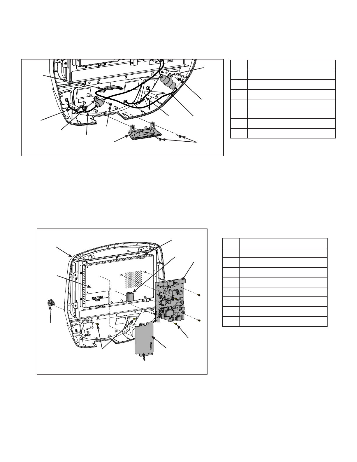
Remove components from bezel assembly
1. Unplug handset cable and thumb control cables from bezel.
4
6
Description
1 Thumb control cable (2)
2 Handset cable
3 Screw (4)
3
1
4
2
3
5
1
7
3
4 Cable clamp (2)
5 E-Stop panel
6 Heart rate sensor
7 Heart rate cable
2. Remove the two screws securing the cable clamps to the bezel using a Phillips screwdriver.
3. Remove the two screws securing the E-Stop panel to the bezel using a Phillips screwdriver.
4. Remove the heart rate sensor from the bezel using a utility knife. Do not damage heart rate
sensor. Note position and orientation of heart rate sensor.
5. Remove the two screws securing the book tabs to the bezel using a Phillips screwdriver.
3
1
5
8
Description
1 Bezel
6
2 Book tab (2)
3 IR sensor
4 Screws (6)
5 Ferrite (optional)
6 MCC board
7 iPod board (optional)
8 Monitor
2
4
4
7
6. Remove the IR sensor, optional ferrite and optional iPod board using a utility knife. Do not
damage IR sensor. Note position and orientation of IR sensor.
7. Remove the four screws securing the MCC board to the monitor using a Phillips screwdriver.
61
Page 62

Cybex Service Manual
Install components on bezel assembly
1. Install the four screws securing the MCC board to the monitor using a Phillips screwdriver.
9
1
8
3
5
6
1 Bezel
2 Book tab (2)
3 IR sensor
4 Screws (6)
5 Ferrite (optional)
6 MCC board
7 iPod board (optional)
8 Monitor
9 Double sided tape
2
4
Description
4
7
2. Install the IR sensor, optional ferrite and optional iPod board using the double sided tape.
Cut tape to size.
3. Install the two screws securing the book tabs to the bezel using a Phillips screwdriver.
4. Install the heart rate sensor to the bezel using double sided tape. Cut tape to size.
8
4
Description
1 Thumb control cable (2)
6
2 Handset cable
3 Screw (4)
3
1
4
3
1
2
5
7
3
4 Cable clamp (2)
5 E-Stop panel
6 Heart rate sensor
7 Heart rate cable
8 Double sided tape
5. Install the two screws securing the E-Stop panel to the bezel using a Phillips screwdriver.
6. Install the two screws securing the cable clamps to the bezel using a Phillips screwdriver.
7. Plug handset cable and thumb control cables to bezel.
62 63
Page 63

Cybex Service Manual
Complete installation
1. Screw the coax cable into the E3 View Monitor.
2. Install the ground cable to the E3 View Monitor using a 11/32” nut driver.
3. Plug optional CSAFE cable into the MCC board.
4. Plug cables into the MCC board.
MCC board cables
1 2 3
5 64
7 8 9
Description
1 CSAFE (optional)
2 Display
3 E3 View monitor
4 A/V
5 Headphone jack
6 iPod (optional)
7 Heart rate
8 Handset membrane
9 iPod board assembly (optional)
Install front cover
Install the four screws securing the front cover to the console assembly using a Phillips screwdriver.
1
Description
1 Console assembly
2 Screws (4)
2
63
Page 64

Cybex Service Manual
Test the unit for proper operation
1. Plug the power cord into the power outlet.
2. Turn the main power switch to the on (I) position.
3. Operate the unit at all levels to verify proper operation.
MCC Board
Tools Required
• Phillips screwdriver
• ESD (Electrostatic Discharge) grounding strap
Disconnect power source
4. Turn the main power switch to the off (O) position.
5. Unplug the power cord from the power outlet.
WARNING: Shock and electrocution hazard
• Unplug unit and let sit 10 minutes before cleaning or performing maintenance
• Electrical charge can remain in unit after unplugging
• Keep water and liquids away from electrical parts
NOTICE: Console damage
Wear an ESD grounding strap during this procedure. Connect ESD grounding strap to
frame bolts or unpainted metal of frame. If ESD grounding strap is not available, touch
frame bolts or unpainted metal of frame before handling any electronics.
Remove front cover
1. Remove the four short screws and one long screw securing the front cover and iPad clip to the
console assembly using a Phillips screwdriver.
1
Description
1 Console assembly
2 Short screws (4)
3
3 iPad clip
4 Long screw (1)
2
4
2. Tilt front cover forward.
64 65
Page 65

Cybex Service Manual
3. Unplug cables from the MCC board by un-latching connectors with the following procedure:
A. Press in the top of the cable connector.
DO NOT PULL
CONNECTOR OUT
BY THE WIRES!
1
B. Ensure the latch disengages the connector.
C. Unplug cable by holding down the latch and pulling straight out from the connector. Do not
pull on wires, remove by connector.
MCC board cables
1 2 3 4
Description
1 Latch
Pull Straight Out
From Connector
Description
1 Wireless audio (optional)
2 CSAFE (optional)
3 Display
4 LED display board
5 Headphone jack
6 iPod (optional)
7 Heart rate
8 Handset membrane
9 iPod board assembly (optional)
5 6 7 8 9
65
Page 66

Cybex Service Manual
4. Unplug optional iPod cable. The iPod cable is held in place by a notch in the access cover.
A. Press in both side latches of the cable connector.
DO NOT PULL
CONNECTOR OUT
BY THE WIRES!
A
C
B
B. Ensure the latches disengage from the connector.
C. Unplug cable by holding down the latches on both sides and pulling straight out from the
connector. Do not pull on wires, remove by connector.
Remove MCC board
Remove the four screws securing the MCC board to the bezel using a Phillips screwdriver.
Description
1 Bezel
2 MCC board
3 Screws (4)
1
2
3
Install new MCC board
Install the four screws securing the new MCC board to the bezel using a Phillips screwdriver.
66 67
Page 67

Complete installation
Plug cables into the new MCC board.
Cybex Service Manual
1 2 3 4
5 6 7 8 9
Install software through internal USB port
Description
1 Wireless audio (optional)
2 CSAFE (optional)
3 Display
4 LED display board
5 Headphone jack
6 iPod (optional)
7 Heart rate
8 Handset membrane
9 iPod board assembly (optional)
1. Tilt console assembly forward and insert USB stick into the internal USB port of the MCC
board. Do NOT insert USB stick into optional E3 View Monitor.
Description
1
1 Console assembly
2 MCC board
2
2. Plug the power cord into the power outlet.
3. Turn the main power switch to the on (I) position.
NOTICE: Console damage may occur
Do NOT turn the power off, press any keys, or remove the USB stick during this
procedure.
67
Page 68

Cybex Service Manual
The software will load into the console. This procedure will take approximately 5 minutes. During this
time there will be beeping noises from the console. When the upload is complete, the display will
show [re][bot].
4. Turn the main power switch to the off (O) position.
5. Remove USB stick from the internal USB port.
Install front cover
Install the four short screws and one long screw securing the front cover and iPad clip to the console
assembly using a Phillips screwdriver.
1
3
2
4
Test the unit for proper operation
1. Turn the main power switch to the on (I) position.
2. Begin striding the unit until the console lights up
3. Operate the unit at all levels to verify proper operation.
Description
1 Console assembly
2 Short screws (4)
3 iPad clip
4 Long screw (1)
68 69
Page 69

Update Software
NOTICE: Repairs and Service
• DO NOT load zip les onto USB stick
• Load un-zipped les onto USB stick
• DO NOT remove USB stick during upload procedure
• Power must remain on during upload procedure
• DO NOT press any keys on console during upload procedure
Cybex Service Manual
USB stick
Software can ONLY be installed on the model it is designed for. Do NOT install this software on other
Arc Trainers, Bikes, or Treadmills.
Prepare USB stick
1. Plug USB stick into PC.
2. Delete any les on USB stick. Verify USB stick is blank.
3. Please go to the Team Cybex service product pages for the latest software les or contact
Cybex Customer Service at 508-533-4300 to receive via email.
4. Unzip le to a folder on PC. Zip le contains one folder labeled “boot”.
5. Copy the “boot” folder to USB stick. DO NOT copy zip le to USB stick.
69
Page 70

Cybex Service Manual
Tools Required
• Phillips screwdriver
• ESD (Electrostatic Discharge) grounding strap.
Disconnect external power source
1. Turn the main power switch to the off (O) position.
2. Unplug the power cord from the power outlet.
WARNING: Shock and electrocution hazard
• Unplug unit and let sit 10 minutes before cleaning or performing maintenance
• Electrical charge can remain in unit after unplugging
• Keep water and liquids away from electrical parts
NOTICE: Component damage
Wear an ESD grounding strap during this procedure. Connect ESD grounding strap to
frame bolts or unpainted metal of frame. If ESD grounding strap is not available, touch
frame bolts or unpainted metal of frame before handling any electronics.
Install software through internal USB port
1. Tilt console assembly forward and insert USB stick into the internal USB port of the MCC
board. Do NOT insert USB stick into optional E3 View Monitor.
Description
1
1 Console assembly
2 MCC board
2
2. Plug the power cord into the power outlet.
3. Turn the main power switch to the on (I) position.
NOTICE: Console damage may occur
Do NOT turn the power off, press any keys, or remove the USB stick during this
procedure.
The software will load into the console. This procedure will take approximately 5 minutes. During this
time there will be beeping noises from the console. When the upload is complete, the display will
show [re][bot].
4. Turn the main power switch to the off (O) position.
70 71
Page 71

Cybex Service Manual
5. Remove USB stick from the internal USB port.
Install front cover
Install the four short screws and one long screw securing the front cover and iPad clip to the console
assembly using a Phillips screwdriver.
1
3
2
4
Test the unit for proper operation
1. Turn the main power switch to the on (I) position.
2. Begin striding the unit until the console lights up
3. Operate the unit at all levels to verify proper operation.
Description
1 Console assembly
2 Short screws (4)
3 iPad clip
4 Long screw (1)
71
Page 72

Cybex Service Manual
72 PB
Page 73

Appendix – Schematic
73
Schematic 525AT
Page 74

74
 Loading...