


®
CPU Cards
CPBH Series
PICMG Single-Board Computer with VGA, Dual GB LAN, SATA, USB, DIO, TV Out, Audio & PC/104
CPBH CEL-24-X: 2.4GHz Celeron CPU
CPBH P4-24-X: 2.4GHz Pentium 4 CPU
CPBH P4-32-X: 3.2 GHz Pentium 4 CPU
USER’S MANUAL
VER. 1.4 • APR 2005
No part of this manual may be reproduced without permission
CyberResearch®, Inc.
www.cyberresearch.com
25 Business Park Dr., Branford, CT 06405 USA 203-483-8815 (9am to 5pm EST) FAX: 203-483-9024

CyberResearch® CPU Cards |
CPBH Series |
©Copyright 2005 All Rights Reserved.
April 22, 2005
The information in this document is subject to change without prior notice in order to improve reliability, design, and function and does not represent a commitment on the part of CyberResearch, Inc.
In no event will CyberResearch, Inc. be liable for direct, indirect, special, incidental, or consequential damages arising out of the use of or inability to use the product or documentation, even if advised of the possibility of such damages.
This document contains proprietary information protected by copyright. All rights are reserved. No part of this manual may be reproduced by any mechanical, electronic, or other means in any form without prior written permission of CyberResearch, Inc.
Trademarks
“CyberResearch,” and “CPBH Series,” are trademarks of CyberResearch, Inc. Other product names mentioned herein are used for identification purposes only and may be trademarks and/or registered trademarks of their respective companies.
• NOTICE •
CyberResearch, Inc. does not authorize any CyberResearch product for use in life support systems, medical equipment, and/or medical devices without the written approval of the President of CyberResearch, Inc. Life support devices and systems are devices or systems which are intended for surgical implantation into the body, or to support or sustain life and whose failure to perform can be reasonably expected to result in injury. Other medical equipment includes devices used for monitoring, data acquisition, modification, or notification purposes in relation to life support, life sustaining, or vital statistic recording. CyberResearch products are not designed with the components required, are not subject to the testing required, and are not submitted to the certification required to ensure a level of reliability appropriate for the treatment and diagnosis of humans.
CyberResearch, Inc. |
iii |
25 Business Park Drive |
P: (203) 483-8815; F: (203) 483-9024 |
Branford, CT USA |
www.cyberresearch.com |

CPBH Series |
CyberResearch® CPU Cards |
Intentionally Blank
iv |
©Copyright 2005 CyberResearch, Inc. |
CyberResearch® CPU Cards |
CPBH Series |
CyberResearch, Inc. |
v |
25 Business Park Drive |
P: (203) 483-8815; F: (203) 483-9024 |
Branford, CT USA |
www.cyberresearch.com |
CPBH Series |
CyberResearch® CPU Cards |
vi |
©Copyright 2005 CyberResearch, Inc |

CyberResearch® CPU Cards |
CPBH Series |
|
|
Table of Contents |
|
Chapter 1 |
General Description .................................. |
1 |
1.1 |
Major Features .............................................................. |
2 |
1.2 |
Specifications ............................................................... |
3 |
1.3 |
Board Dimensions........................................................ |
4 |
Chapter 2 |
Unpacking.................................................. |
5 |
2.1 |
Opening the Delivery Package.................................... |
5 |
2.2 |
Inspection...................................................................... |
5 |
Chapter 3 |
Hardware Installation .............................. |
7 |
3.1 |
Before Installation ........................................................ |
7 |
3.2 |
Board Layout ................................................................ |
8 |
3.3 |
Jumper List ................................................................... |
9 |
3.4 |
Connector List .............................................................. |
9 |
3.5 |
Configuring the CPU .................................................. |
10 |
3.6 |
System Memory .......................................................... |
10 |
3.7 |
VGA Controller............................................................ |
10 |
3.8 |
Serial ATA Function.................................................... |
12 |
3.9 |
PCI E-IDE Drive Connector........................................ |
13 |
3.10 |
Floppy Disk Drive Connector .................................... |
15 |
3.11 |
Serial Port Connectors............................................... |
16 |
3.12 |
IrDA Connector ........................................................... |
17 |
3.13 |
Parallel Connector...................................................... |
18 |
3.14 |
Ethernet Connector.................................................... |
19 |
3.15 |
USB Connector ........................................................... |
19 |
3.16 |
CMOS Data Clear ........................................................ |
20 |
3.17 |
Power and Fan Connectors....................................... |
20 |
3.18 |
Keyboard/Mouse Connector ..................................... |
22 |
3.19 |
System Front Panel Connectors............................... |
22 |
3.20 |
Watchdog Timer.......................................................... |
23 |
3.21 |
Audio Connectors ...................................................... |
24 |
3.22 |
TV-Out Function.......................................................... |
24 |
3.23 |
PC/104 Connectors..................................................... |
25 |
CyberResearch, Inc. |
iv |
25 Business Park Drive |
P: (203) 483-8815; F: (203) 483-9024 |
Branford, CT USA |
www.cyberresearch.com |

CPBH Series |
CyberResearch® CPU Cards |
|
Chapter 4 |
Award BIOS Setup ................................. |
27 |
4.1 |
Starting Setup ............................................................. |
27 |
4.2 |
Using Setup................................................................. |
28 |
4.3 |
Main Menu ................................................................... |
29 |
4.4 |
Standard CMOS Features .......................................... |
30 |
4.5 |
Advanced BIOS Features .......................................... |
31 |
4.6 |
Advanced Chipset Features ...................................... |
32 |
4.7 |
Integrated Peripherals................................................ |
33 |
4.8 |
Power Management Setup......................................... |
35 |
4.9 |
PnP/PCI Configurations............................................. |
36 |
4.10 |
PC Health Status......................................................... |
36 |
4.11 |
Frequency/Voltage Control........................................ |
37 |
4.12 |
Load Fail-Safe Defaults.............................................. |
37 |
4.13 |
Load Optimized Defaults ........................................... |
38 |
4.14 |
Set Supervisor/User Password................................. |
39 |
4.15 |
Save & Exit Setup ....................................................... |
40 |
4.16 |
Exit Without Saving.................................................... |
41 |
Chapter 5 |
Software Utilities..................................... |
43 |
5.1 |
IDE Driver Installation ................................................ |
43 |
5.1.1 |
Installing Intel Chipset Software Utility .................................. |
43 |
5.2 |
VGA Driver Installation............................................... |
46 |
5.3 |
LAN Driver Installation............................................... |
48 |
5.3.1 |
Win 95/98/2K/XP................................................................................. |
48 |
5.3.2 |
Win NT ........................................................................................................ |
50 |
5.4 |
Audio Driver Installation ............................................ |
58 |
5.5 |
USB2.0 Driver Installation.......................................... |
60 |
5.5.1 |
Win 95/98................................................................................................ |
60 |
5.5.2 |
Win 2000 ................................................................................................... |
61 |
5.5.3 |
Win XP ........................................................................................................ |
65 |
vii |
©Copyright 2005 CyberResearch, Inc |
CyberResearch® CPU Cards |
CPBH Series |
Safety Instructions
Integrated circuits on computer boards are sensitive to static electricity. To avoid damaging chips from electrostatic discharge, observe the following precautions:
Do not remove boards or integrated circuits from their anti-static packaging until you are ready to install them.
Before handling a board or integrated circuit, touch an unpainted portion of the system unit chassis for a few seconds. This helps to discharge any static electricity on your body.
Wear a wrist-grounding strap, available from most electronic component stores, when handling boards and components. Fasten the ALLIGATOR clip of the strap to the end of the shielded wire lead from a grounded object. Please wear and connect the strap before handling the CPBH to protect yourself from the discharge of any static electricity through the strap.
Please use an anti-static pad when putting down any components or parts or tools outside the computer. You may also use an anti-static bag instead of the pad. Please inquire from your local supplier for additional assistance in finding the necessary anti-static gadgets.
NOTE: DO NOT TOUCH THE BOARD OR ANY OTHER SENSITIVE COMPONENT WITHOUT ALL NECESSARY ANTI-STATIC PROTECTION.
CyberResearch, Inc. |
viii |
25 Business Park Drive |
P: (203) 483-8815; F: (203) 483-9024 |
Branford, CT USA |
www.cyberresearch.com |
CPBH Series |
CyberResearch® CPU Cards |
ix |
©Copyright 2005 CyberResearch, Inc |
CyberResearch® CPU Cards |
CPBH Series |
Chapter 1
General Description
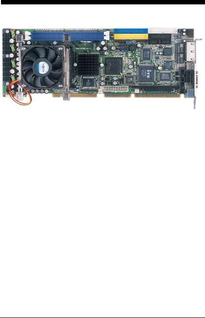
The CPBH is an Intel® 82865GV/82801EB chipset-based board designed for PICMG Bus PGA 478 Intel® Pentium® 4 CPU with speed of up to 3.2GHz CPU. The combination of these features makes the CPBH an ideal all-in-one industrial single board computer. Additional features include an enhanced I/O with CRT/LVDS Panel, TV-Out, dual Giga LAN, audio, serial ATA, 4 COM port interface, and more.
Its onboard ATA/33/66/100 connected to IDE drive interface architecture allows the CPBH to support data transfers of 33, 66 or 100MB/sec. for each IDE drive connection. Designed with the Intel® 82865GV/82801EB core logic chipset, the board supports all PGA 478 Pentium® 4 CPU series with Intel® Hyper-Threading Technology clocking up to 3.2GHz. The display controller is Intel 82865GV with 1MB/8MB/16MB memory supporting CRT display up to 1600 x 1200 x 32-bit at 60Hz.
Serial ATA is the revolutionary ATA interface that provides scalable performance for IDE device. With up to 150MB/sec. data transfer rate, serial ATA is faster than the current parallel ATA and delivers superior input/output performance. In addition, the serial ATA interface is furnished with RAID 0/1 function for extra performance enhancement and data protection.
CyberResearch, Inc. |
1 |
25 Business Park Drive |
P: (203) 483-8815; F: (203) 483-9024 |
Branford, CT USA |
www.cyberresearch.com |
CPBH Series |
CyberResearch® CPU Cards |
System memory is also sufficient with the two DDR sockets that can support DDR-266/333/400 up to 2GB. 800MHz FSB CPU can support DDR-400, 533MHz FSB CPU, can support DDR-333, and 400MHz FSB CPU can support DDR-266.
Additional onboard connectors include an advanced USB2.0 and IrDA port providing faster data transmission, and two external RJ-45 connectors for use of one 100/1000 and one 10/100 OR two 10/100 Base-TX Ethernet interfaces.
1.1 Major Features
The CPBH comes with the following features:
¾PGA 478 for Intel® Pentium® 4 CPU with Hyper-Threading Technology clocking up to 3.2GHz
¾Supports 400/533/800MHz FSB
¾Two DDR sockets with a max. capacity of 2GB
¾Intel 82865GV/82801EB system chipset
¾Winbond W83627 super I/O chipset
¾Intel® 82865GV display controller
¾Intel® 82562EZ (or 82547EI) and 82540 LAN controller
¾AC97 3D audio controller
¾Serial ATA controller
¾Fast PCI ATA/33/66/100 IDE controller
¾Four COM, seven USB2.0, PC/104 connector
¾Hardware Monitor function
¾LVDS Panel display interface (optional)
¾TV-Out function (optional)
2 |
©Copyright 2005 CyberResearch, Inc |

CyberResearch® CPU Cards |
CPBH Series |
1.2Specifications
CPU: PGA 478 for Intel® Pentium® 4 CPU with Hyper-Threading Technology up to 3.2GHz
Bus Interface: PICMG Bus
Front Side Bus: Supports 400/533/800MHz FSB
Memory: Two DDR sockets supporting DDR-266/333/400 up to 2GB
Chipset: Intel® 82865GV/82801EB
I/O Chipset: Winbond W83627
ISA Bridge: ITE IT8888 (16-bit)
VGA: Intel® 82865GV with 1MB/8MB/16MB shared main memory supporting CRT display up to 1600 x 1200 at 32-bit colors at 60Hz
LVDS Panel: Supports LVDS interface (optional)
TV-Out: Supports PAL or NTSC TV systems (optional)
LAN: Intel® 82562EZ 10/100 Based (or 82547EI 100/1000 Based) and 82540 100/1000 Based LAN
Audio: AC97 3D audio controller
Serial ATA: Intel® ICH5 controller and with two ports supporting transfer rate up to 150MB/sec.
IDE: Four IDE disk drives supporting ATA/33/66/100 and with transfer rates of up to 33/66/100MB/sec.
FDD: Supports up to two floppy disk drives
Parallel: One enhanced bi-directional parallel port supporting SPP/ECP/EPP
Serial Port: 16C550 UART-compatible RS-232/422/485 x 1 and RS-232 x 3 serial ports with 16-byte FIFO
PC/104: PC/104 connector for 16-bit ISA Bus
IrDA: One IrDA TX/RX header
USB: Seven USB2.0 ports, six internal and one external
Keyboard/Mouse: PS/2 6-pin Mini DIN
BIOS: Award PnP Flash BIOS
Watchdog Timer: Software programmable time-out intervals from 1~256sec.
CMOS: Battery backup
Temperature: 0~60°C (operating)
Hardware Monitor: Winbond W83627
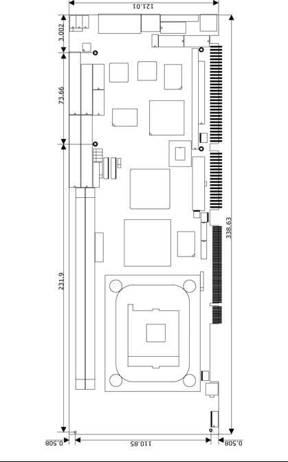
Board Size: 33.8(L) x 12.1(W) cm
CyberResearch, Inc. |
3 |
25 Business Park Drive |
P: (203) 483-8815; F: (203) 483-9024 |
Branford, CT USA |
www.cyberresearch.com |
CPBH Series |
CyberResearch® CPU Cards |
1.3Board Dimensions
4 |
©Copyright 2005 CyberResearch, Inc |

CyberResearch® CPU Cards |
CPBH Series |
Chapter 2
Unpacking
2.1Opening the Delivery Package
The CPBH is packed in an anti-static bag. The board has components that are easily damaged by static electricity. Do not remove the anti-static wrapping until proper precautions have been taken. Safety Instructions in front of this manual describe anti-static precautions and procedures.
2.2Inspection
After unpacking the board, place it on a raised surface and carefully inspect the board for any damage that might have occurred during shipment. Ground the board and exercise extreme care to prevent damage to the board from static electricity.
Integrated circuits will sometimes come out of their sockets during shipment. Make sure all integrated circuits, particularly the BIOS, processor, memory modules, ROM-Disk, and keyboard controller chip are firmly seated. The CPBH delivery package contains the following items:
CPBH Board x 1
Utility CD Disk x 1
Cables Package x 1
Cooling Fan x 1
Jumper Bag x 1
User’s Manual
CyberResearch, Inc. |
5 |
25 Business Park Drive |
P: (203) 483-8815; F: (203) 483-9024 |
Branford, CT USA |
www.cyberresearch.com |

CPBH Series |
CyberResearch® CPU Cards |
|
Cables Package |
NO. |
Description |
1 |
ATA/100 IDE flat cable x 2 |
2 |
Floppy flat cable x 1 |
3 |
MIC/Audio 8-pin cable + 2 phone jacks x 1 |
4 |
Serial ATA cable x 1 |
5 |
Two COM + RCA jack x 1 |
6 |
PS/2 KB/MS transfer cable x 1 |
7 |
5-pin ATX power cable x 1 |
8 |
8-pin USB split type cable with bracket x 1 |
9 |
Two COM flat cable with bracket x 1 |
10 |
Parallel port flat cable with bracket x 1 |
It is recommended that you keep all the parts of the delivery package intact and store them in a safe/dry place for any unforeseen event requiring the returned shipment of the product. In case you discover any missing and/or damaged items from the list of items, please contact your dealer immediately.
6 |
©Copyright 2005 CyberResearch, Inc |

CyberResearch® CPU Cards |
CPBH Series |
Chapter 3
Hardware Installation
This chapter provides the information on how to install the hardware using the CPBH. This chapter also contains information related to jumper settings of switch, watchdog timer selection, etc.
3.1Before Installation
After confirming your package contents, you are now ready to install your hardware. The following are important reminders and steps to take before you begin with your installation process.
1.Make sure that all jumper settings match their default settings and CMOS setup correctly. Refer to the sections on this chapter for the default settings of each jumper. (Set JP3 1-2)
2.Go through the connections of all external devices and make sure that they are installed properly and configured correctly within the CMOS setup. Refer to the sections in this chapter for the detailed information on the connectors.
3.Keep the manual and diskette in good condition for future reference and use.
4.Make sure your power supply is you use is for P4 only. One of 4-pin connectors is for +12V lead which should be connected to CN1 connector of the CPBH.
CyberResearch, Inc. |
7 |
25 Business Park Drive |
P: (203) 483-8815; F: (203) 483-9024 |
Branford, CT USA |
www.cyberresearch.com |
CPBH Series |
CyberResearch® CPU Cards |
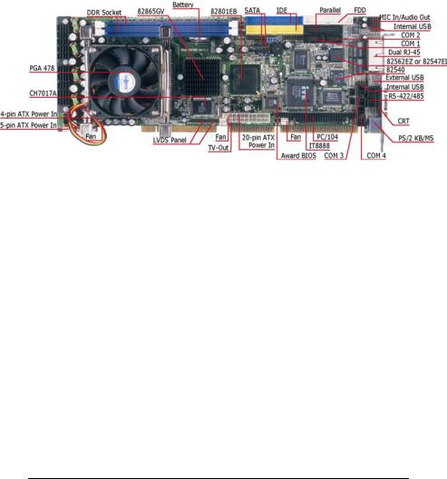
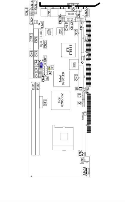
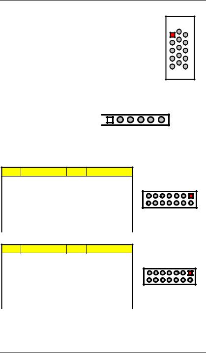
3.2Board Layout
8 |
©Copyright 2005 CyberResearch, Inc |
CyberResearch® CPU Cards CPBH Series
3.3 Jumper List |
|
|
|
Jumper |
Default Setting |
Setting |
Page |
JP1/JP2/JP4/JP5 |
Use RS-232 or RS-422/485 Select: |
2-3 Short |
16 |
|
RS-232 |
|
|
JP3 |
Clear CMOS: Normal Operation |
1-2 Short |
20 |
3.4 |
Connector List |
|
|
|
Connector |
Definition |
Page |
|
CN1/CN5 |
4-pin/20-pin ATX Power Connectors |
20 |
|
CN3(1-3-5-7) |
Speaker Connector |
22 |
|
CN3(9-11) |
Reset Button Connector |
22 |
|
CN3(13-15) |
HDD LED Switch |
22 |
|
CN3(2-4-6-8) |
Power LED Connector |
22 |
|
CN3(10-12) |
2-pin ATX Power ON/OFF Connector |
22 |
|
CN3(14-16) |
Green LED Connector |
22 |
|
CN4 |
IrDA Connector |
17 |
|
CN7/CN6 |
Primary/Secondary IDE Connectors |
13 |
CN21/CN8/CN12/CN14 |
COM1~COM4 Connectors (5x2 header) |
16 |
|
|
CN9 |
Parallel Connector |
18 |
|
CN10 |
FDD Connector |
15 |
|
CN11 |
RS-422/485 Connector (5x2 header) |
16 |
CN13/CN16/CN17 |
USB2.0 Connectors |
19 |
|
|
CN15 |
MIC In/Audio Out Connector |
24 |
|
CN18 |
Dual RJ-45 Connector |
19 |
|
CN19 |
External USB Connector |
19 |
|
CN20 |
15-pin CRT Connector |
10 |
|
CN22 |
PS/2 6-pin Mini DIN KB/MS Connector |
22 |
|
CN23 |
5-pin ATX Power Connector |
20 |
|
CN24 |
Line In Connector |
|
|
DM1/DM2 |
DDR Sockets |
10 |
|
J1 |
Inverter Power Connector |
10 |
|
J2 |
LVDS Connector |
10 |
|
J3 |
LVDS Connector |
10 |
|
J5 |
TV-Out Connector |
24 |
|
J6 / J7 |
Serial ATA Connector |
12 |
FN1 / FN2 / FN3 |
Fan Power Connector |
20 |
|
|
PC2 / PC3 |
PC/104 64-pin/40-pin Connector |
25 |
CyberResearch, Inc. |
9 |
25 Business Park Drive |
P: (203) 483-8815; F: (203) 483-9024 |
Branford, CT USA |
www.cyberresearch.com |

CPBH Series |
CyberResearch® CPU Cards |
3.5Configuring the CPU
The CPBH offers the convenience in CPU installation with its auto-detect feature. After installing a new microprocessor onboard, the CPBH automatically identifies the frequency and clock speed of the installed microprocessor chip, thereby eliminating the need for user to do additional CPU configuration or hardware settings related to it.
The CPBH provides 400MHz/533MHz/800MHz FSB, and the all-in-one solution for the latest Intel® Pentium 4 processor with 800MHz FSB and Hyper-Threading Technology.
NOTE: CPU Vcore should be located in the range of 0.8375V to 1.6V, otherwise system won’t boot.
3.6System Memory
The CPBH provides two DDR sockets at locations DM1 and DM2. The maximum capacity of the onboard memory is 2GB. 800MHz FSB CPU can support DDR-266/333/400, 533MHz FSB CPU can support DDR-266/333, and 400MHz FSB CPU can support DDR-266.
FSB \ Memory CLK |
DDR-266 |
DDR-333 |
DDR-400 |
800MHz FSB |
Yes |
Yes |
Yes |
533MHz FSB |
Yes |
Yes |
No |
400MHz FSB |
Yes |
No |
No |
3.7VGA Controller
The onboard Intel® 82865GV with 1MB/8MB/16MB (default) memory supports CRT displays up to 1600 x 1200 x 32-bit. The CPBH provides two methods of connecting VGA device. CN20 offers a single standard CRT connector (DB15). And J2, J3 offers LVDS Panel connectors.
10 |
©Copyright 2005 CyberResearch, Inc |
CyberResearch® CPU Cards |
CPBH Series |
z CN20: 15-pin CRT Connector (DB15)
PIN |
Description |
PIN |
Description |
1 |
Red |
2 |
Green |
3 |
Blue |
4 |
N/C |
5 |
GND |
6 |
GND |
7 |
GND |
8 |
GND |
9 |
N/C |
10 |
GND |
11 |
N/C |
12 |
SDA |
13 |
HSYNC |
14 |
VSYNC |
15 |
SCL |
|
|
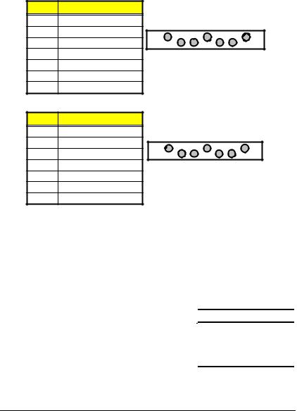
z J1: Inverter Power Connector
PIN |
Description |
|
|
|
|
|
|
|
1 |
VCC12 |
1 |
2 |
3 |
4 |
5 |
||
2 |
VCC12 |
|
|
|
|
|
|
|
|
|
|
|
|
|
|
||
3 |
VCC5 |
|
|
VCC12 |
VCC12 |
VCC5 |
ENABKL |
ENAVDD |
|
|
|||||||
4 |
ENABKL |
|
|
|||||
|
|
|
|
|
|
|
||
5 |
ENAVDD |
|
|
|
|
|
|
|
6 |
GND |
|
|
|
|
|
|
|
|
6 |
1 |
11 |
5 10 15
6
GND
z J3: LVDS Panel Connector
PIN Description PIN Description
1 |
VCC3 |
2 |
VCC3 |
3 |
GND |
4 |
GND |
5 |
A0M |
6 |
A0P |
7 |
A1M |
8 |
A1P |
9 |
A2M |
10 |
A2P |
11 |
CLK1M |
12 |
CLK1P |
13 |
A3M |
14 |
A3P |
A3M |
CLK1M |
A2M |
A1M |
A0M |
GND |
VCC3 |
13 |
|
|
|
|
|
1 |
14 |
|
|
|
|
|
2 |
A3P |
CLK1P |
A2P |
A1P |
A0P |
GND |
VCC3 |
z J2: LVDS Panel Connector
PIN Description PIN Description
1 |
VCC3 |
2 |
VCC3 |
3 |
GND |
4 |
GND |
5 |
A4M |
6 |
A4P |
7 |
A5M |
8 |
A5P |
9 |
A6M |
10 |
A6P |
11 |
CLK2M |
12 |
CLK2P |
13 |
A7M |
14 |
A7P |
A7M |
CLK2M |
A6M |
A5M |
A4M |
GND |
VCC3 |
13 |
|
|
|
|
|
1 |
14 |
|
|
|
|
|
2 |
A7P |
CLK2P |
A6P |
A5P |
A4P |
GND |
VCC3 |
CyberResearch, Inc. |
11 |
25 Business Park Drive |
P: (203) 483-8815; F: (203) 483-9024 |
Branford, CT USA |
www.cyberresearch.com |
CPBH Series |
CyberResearch® CPU Cards |
3.8Serial ATA Function
You can connect the Serial ATA device to this connector which provides you high speed transfer rates (150MB/sec.). If you wish to use RAID function, please note that these two Serial ATA connectors just support RAID0 and only compatible with WIN XP.
z J7: Serial ATA Connector
PIN Description
1GND
2SATA0TXP
3SATA0TXN
4GND
5SATA0RXN
6SATA0RXP
7GND
1 |
|
|
|
|
|
7 |
GND |
SATA0TXP |
SATA0TXN |
GND |
SATA0RXN |
SATA0RXP |
GND |
z J6: Serial ATA Connector
PIN Description
1GND
2SATA1TXP
3SATA1TXN
4GND
5SATA1RXN
6SATA1RXP
7GND
1 |
|
|
|
|
|
7 |
GND |
SATA1TXP |
SATA1TXN |
GND |
SATA1RXN |
SATA1RXP |
GND |
IDE and Serial ATA Device Configurations
Following are the IDE and Serial ATA device configurations supported by Intel ICH5 specifications.
Native operating systems (OS) are Windows 2000/XP. ICH5 supports a maximum of six devices using these OS.
Legacy OS are MS-DOS, Windows 95/98/Me/NT4.0. ICH5 supports a maximum of four devices using these OS.
Operating System |
IDE |
|
Serial ATA |
WIN 2000/XP |
Primary/Secondary |
|
Port0/Port1 |
WIN 95/98/Me/NT4.0 |
Primary |
|
Port0/Port1 |
Secondary |
|
Port0/Port1 |
|
|
Primary/Secondary |
|
---- |
12 |
©Copyright 2005 CyberResearch, Inc |
CyberResearch® CPU Cards |
CPBH Series |
3.9PCI E-IDE Drive Connector
CN7 and CN6 are standard 40-pin daisy-chain driver connectors that serve the PCI E-IDE drive provisions onboard the CPBH. A maximum of four ATA/33/66/100 IDE drives can be connected to the CPBH via
CN7 and CN6.
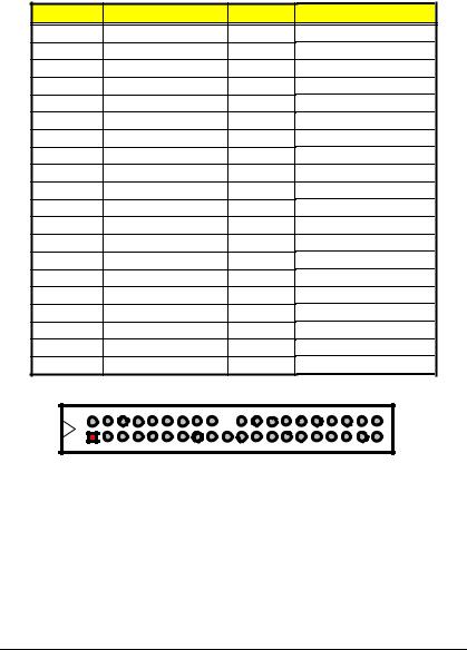
z CN7: Primary IDE Connector
PIN |
Description |
PIN |
|
Description |
||||||||||
1 |
|
|
RESET |
|
|
2 |
|
|
|
|
GND |
|||
3 |
|
PDATA 7 |
|
|
4 |
|
|
|
|
PDATA 8 |
||||
5 |
|
PDATA 6 |
|
|
6 |
|
|
|
|
PDATA 9 |
||||
7 |
|
PDATA 5 |
|
|
8 |
|
|
|
PDATA 10 |
|||||
9 |
|
PDATA 4 |
|
|
10 |
|
|
PDATA 11 |
||||||
11 |
|
PDATA 3 |
|
|
12 |
|
|
PDATA 12 |
||||||
13 |
|
PDATA 2 |
|
|
14 |
|
|
PDATA 13 |
||||||
15 |
|
PDATA 1 |
|
|
16 |
|
|
PDATA 14 |
||||||
17 |
|
PDATA 0 |
|
|
18 |
|
|
PDATA 15 |
||||||
19 |
|
|
GND |
|
|
20 |
|
|
|
|
N/C |
|||
21 |
|
|
PDREQ |
|
|
22 |
|
|
|
GND |
||||
23 |
|
|
PIOW# |
|
|
24 |
|
|
|
GND |
||||
25 |
|
|
PIOR# |
|
|
26 |
|
|
|
GND |
||||
27 |
|
PIORDY |
|
|
28 |
|
|
|
PR1PD1- |
|||||
29 |
|
RPDACK- |
|
|
30 |
|
|
|
GND |
|||||
31 |
|
|
Interrupt |
|
|
32 |
|
|
|
|
N/C |
|||
33 |
|
|
PDA1- |
|
|
34 |
|
|
|
PATA66 |
||||
35 |
|
|
PDA0- |
|
|
36 |
|
|
|
PDA2- |
||||
37 |
|
|
PDCS1- |
|
|
38 |
|
|
|
RPCS3- |
||||
39 |
HDD Active P |
|
|
40 |
|
|
|
GND |
||||||
4 |
6 |
8 |
10 |
12 |
14 16 |
18 |
20 22 |
24 |
26 28 |
30 |
32 |
34 |
36 |
38 |
2 |
|
|
|
|
|
|
|
|
|
|
|
|
|
40 |
1 |
|
|
|
|
|
|
|
|
|
|
|
|
|
39 |
3 |
5 |
7 |
9 |
11 |
13 15 |
17 |
19 21 |
23 |
25 27 |
29 |
31 |
33 |
35 |
37 |
CyberResearch, Inc. |
13 |
25 Business Park Drive |
P: (203) 483-8815; F: (203) 483-9024 |
Branford, CT USA |
www.cyberresearch.com |

CPBH Series |
CyberResearch® CPU Cards |
zCN6: Secondary IDE Connector
PIN |
Description |
PIN |
|
Description |
||||||||||
1 |
|
|
RESET |
|
|
2 |
|
|
|
|
GND |
|||
3 |
|
SDATA 7 |
|
|
4 |
|
|
|
|
SDATA 8 |
||||
5 |
|
SDATA 6 |
|
|
6 |
|
|
|
|
SDATA 9 |
||||
7 |
|
SDATA 5 |
|
|
8 |
|
|
|
SDATA 10 |
|||||
9 |
|
SDATA 4 |
|
|
10 |
|
|
SDATA 11 |
||||||
11 |
|
SDATA 3 |
|
|
12 |
|
|
SDATA 12 |
||||||
13 |
|
SDATA 2 |
|
|
14 |
|
|
SDATA 13 |
||||||
15 |
|
SDATA 1 |
|
|
16 |
|
|
SDATA 14 |
||||||
17 |
|
SDATA 0 |
|
|
18 |
|
|
SDATA 15 |
||||||
19 |
|
|
GND |
|
|
20 |
|
|
|
|
N/C |
|||
21 |
|
|
SDREQ |
|
|
22 |
|
|
|
GND |
||||
23 |
|
|
SIOW# |
|
|
24 |
|
|
|
GND |
||||
25 |
|
|
SIOR# |
|
|
26 |
|
|
|
GND |
||||
27 |
|
SIORDY |
|
|
28 |
|
|
|
PR1SD1- |
|||||
29 |
|
SDDACK- |
|
|
30 |
|
|
|
GND |
|||||
31 |
|
|
Interrupt |
|
|
32 |
|
|
|
|
N/C |
|||
33 |
|
|
SDA1- |
|
|
34 |
|
|
|
SATA66 |
||||
35 |
|
|
SDA0- |
|
|
36 |
|
|
|
SDA2- |
||||
37 |
|
|
SDCS1- |
|
|
38 |
|
|
|
SDCS3- |
||||
39 |
HDD Active S |
|
|
40 |
|
|
|
GND |
||||||
4 |
6 |
8 |
10 |
12 |
14 16 |
18 |
20 22 |
24 |
26 28 |
30 |
32 |
34 |
36 |
38 |
2 |
|
|
|
|
|
|
|
|
|
|
|
|
|
40 |
1 |
|
|
|
|
|
|
|
|
|
|
|
|
|
39 |
3 |
5 |
7 |
9 |
11 |
13 15 |
17 |
19 21 |
23 |
25 27 |
29 |
31 |
33 |
35 |
37 |
14 |
©Copyright 2005 CyberResearch, Inc |
 Loading...