

Page 1
CPU Cards
CEGA Series
PICMG 1.3 Single-Board Computers
Featuring VGA, SATA, RAID, Dual Gb
LAN & IrDA Modules
CEGA PD-32-X: 3.2GHz Pentium D CPU
CEGA PD-36-X
CEGA C2-24-X: 2.4GHz Core 2 Duo CPU
: 3.6GHz Pentium D CPU
®
USER’S MANUAL
VER. 1.2C • SEP 2007
No part of this manual may be reproduced without permission
CyberResearch®,Inc.
www.cyberresearch.com
25 Business Park Dr., Branford, CT 06405 USA
203-483-8815 (9am to 5pm EST) FAX: 203-483-9024
Page 2

Page 3

CyberResearch® CPU Cards CEGA Series
©Copyright 2007
All Rights Reserved.
September 7, 2007
The information in this document is subject to change without prior notice
in order to improve reliability, design, and function and does not represent
a commitment on the part of CyberResearch, Inc.
In no event will CyberResearch, Inc. be liable for direct, indirect, special,
incidental, or consequential damages arising out of the use of or inability
to use the product or documentation, even if advised of the possibility of
such damages.
This document contains proprietary information protected by copyright.
All rights are reserved. No part of this manual may be reproduced by any
mechanical, electronic, or other means in any form without prior written
permission of CyberResearch, Inc.
Trademarks
“CyberResearch,” and “CEGA Series,” are trademarks of CyberResearch,
Inc. Other product names mentioned herein are used for identification
purposes only and may be trademarks and/or registered trademarks of
their respective companies.
• NOTICE •
CyberResearch, Inc. does not authorize any CyberResearch product for
use in life support systems, medical equipment, and/or medical devices
without the written approval of the President of CyberResearch, Inc. Life
support devices and systems are devices or systems which are intended
for surgical implantation into the body, or to support or sustain life and
whose failure to perform can be reasonably expected to result in injury.
Other medical equipment includes devices used for monitoring, data
acquisition, modification, or notification purposes in relation to life
support, life sustaining, or vital statistic recording. CyberResearch
products are not designed with the components required, are not subject
to the testing required, and are not submitted to the certification required
to ensure a level of reliability appropriate for the treatment and diagnosis of
humans.
CyberResearch, Inc. iii
25 Business Park Drive P: (203) 483-8815; F: (203) 483-9024
Branford, CT USA www.cyberresearch.com
Page 4

CEGA Series CyberResearch® CPU Cards
Revision History
Title CyRAQ 06SB Series
Revision # Description Date of Issue
1.1 Initial Release May 10th 2007
1.2C
Revision – update USB
Functionality/Connectivity
September 7th 2007
iv ©Copyright 2007 CyberResearch, Inc.
Page 5

CyberResearch® CPU Cards CEGA Series
Packing List
If any of the components listed in the checklist below are missing, please do not proceed
with the installation. Contact CyberResearch, Inc. technical support. Call 203-483-8815
and ask for technical support, fax 203-483-9024 attn: tech support, or e-mail
techsupport@cyberresearch.com
.
The items listed below should all be included in the CEGA CPU card package.
1 x CEGA single board computer
1 x ATX-12V cabl e
1 x Mini jumper pack
1 x ATA 66/100 flat cable
4 x SATA cable
2 x SATA power cable
1 x KB/MS Y cable
1 x RS-232 cable (2 COM Ports)
1 x USB cable
1 x Utility CD
Images of the above items are shown in Chapter 3.
CyberResearch, Inc. v
25 Business Park Drive P: (203) 483-8815; F: (203) 483-9024
Branford, CT USA www.cyberresearch.com
Page 6

CEGA Series CyberResearch® CPU Cards
Table of Contents
1 INTRODUCTION..................................................................................................... 1
1.1
CEGA OVERVIEW...................................................................................................... 2
1.1.1 CEGA Features.................................................................................................. 2
1.2 CEGA OVERVIEW...................................................................................................... 3
1.2.1 CEGA Overview Photo...................................................................................... 3
1.2.2 CEGA Peripheral Connectors and Jumpers...................................................... 4
1.2.3 Technical Specifications..................................................................................... 5
2 DETAILED SPECIFICATIONS............................................................................11
2.1 OVERVIEW ............................................................................................................... 12
2.2 DIMENSIONS............................................................................................................. 12
2.2.1 Board Dimensions............................................................................................ 12
2.2.2 External Interface Panel Dimensions.............................................................. 13
2.3 DATA FLOW.............................................................................................................. 14
2.4 COMPATIBLE PROCESSORS ....................................................................................... 15
2.4.1 CPU Overview................................................................................................. 15
2.4.2 Supported Intel® Core™ 2 Duo Processors ................................................... 15
2.4.3 Supported Intel® Pentium® 4 Processors....................................................... 15
2.4.4 Supported Intel® Pentium® D Processors...................................................... 16
2.4.5 Supported Intel® Celeron® D Processors ...................................................... 16
2.5 INTEL
®
945G NORTHBRIDGE CHIPSET...................................................................... 16
2.5.1 Intel® 945G Overview...................................................................................... 16
2.5.2 Intel® 945G Memory Support .......................................................................... 17
2.5.3 Intel® 945G Serial Digital Video Output (SDVO)............................................ 17
2.5.4 Intel® 945G Integrated Graphics Media Accelerator 950............................... 18
2.6 INTEL
®
ICH7R SOUTHBRIDGE CHIPSET................................................................... 19
2.6.1 Intel® ICH7R Overview.................................................................................... 19
2.6.2 Intel® ICH7R Audio Codec ’97 Controller...................................................... 20
2.6.3 Intel® ICH7R IDE Interface............................................................................. 20
2.6.4 Intel® ICH7R Low Pin Count (LPC) Interface................................................ 22
2.6.5 Intel® ICH7R PCI Interface............................................................................. 22
vi ©Copyright 2007 CyberResearch, Inc
Page 7

CyberResearch® CPU Cards CEGA Series
2.6.6 ® ICH7R Real Time Clock ................................................................................ 23
2.6.7 Intel® ICH7R SATA Controller ........................................................................ 23
®
2.6.8 Intel
ICH7R USB Controller.......................................................................... 23
2.7 PCI BUS COMPONENTS ............................................................................................ 23
2.7.1 PCI Bus Overview............................................................................................ 23
2.7.2 PCI Express (PCIe) Slot Connector................................................................. 23
2.7.3 Broadcom PCIe GbE interface........................................................................ 24
2.8
LPC BUS COMPONENTS ........................................................................................... 25
2.8.1 LPC Bus Overview........................................................................................... 25
2.8.2 BIOS Chipset.................................................................................................... 25
2.8.3 Super I/O Chipset............................................................................................. 25
2.8.3.1 Super I/O LPC Interface ........................................................................... 26
2.8.3.2 Super I/O 16C550 UARTs........................................................................ 26
2.8.3.3 Super I/O Hardware Monitor.................................................................... 26
2.8.3.4 Super I/O Fan Speed Controller................................................................ 26
2.8.3.5 Super I/O Floppy Disk Controller............................................................. 27
2.8.3.6 Super I/O Parallel Port.............................................................................. 27
2.8.3.7 Super I/O Keyboard Controller................................................................. 27
2.9 ENVIRONMENTAL AND POWER SPECIFICATIONS ....................................................... 27
2.9.1 System Monitoring........................................................................................... 27
2.9.2 Operating Temperature and Temperature Control........................................... 28
2.9.3 Power Consumption......................................................................................... 29
3 UNPACKING .......................................................................................................... 30
ANTI-STATIC PRECAUTIONS...................................................................................... 31
3.1
3.2 UNPACKING.............................................................................................................. 31
3.2.1 Unpacking Precautions.................................................................................... 31
3.3 UNPACKING CHECKLIST........................................................................................... 31
3.3.1 Package Contents............................................................................................. 32
4 CONNECTOR PINOUTS...................................................................................... 34
4.1 PERIPHERAL INTERFACE CONNECTORS..................................................................... 35
4.1.1 CEGA Layout................................................................................................... 35
4.1.2 Peripheral Interface Connectors ..................................................................... 35
4.1.3 External Peripheral Interface Panel Connectors............................................ 36
CyberResearch, Inc. vii
25 Business Park Drive P: (203) 483-8815; F: (203) 483-9024
Branford, CT USA www.cyberresearch.com
Page 8

CEGA Series CyberResearch® CPU Cards
4.2 INTERNAL PERIPHERAL CONNECTORS...................................................................... 36
4.2.1 +12V ATX Power Supply Connector ............................................................... 37
4.2.2 Audio Connector (10-pin)................................................................................ 38
4.2.3 Digital Input/Output (DIO) Connector............................................................ 39
4.2.4 Fan Connectors................................................................................................ 40
4.2.5 Floppy Disk Connector (34-pin)...................................................................... 41
4.2.6 Front Panel Connector (12-pin)...................................................................... 43
4.2.7 IDE Connector (40-pin)................................................................................... 43
4.2.8 Infrared Interface Connector (5-pin)............................................................... 45
4.2.9 Keyboard Connector........................................................................................ 46
4.2.10 Parallel Port Connector ................................................................................ 47
4.2.11 SATA Drive Connectors.................................................................................. 49
4.2.12 Serial Port Connector (COM1 and COM2)................................................... 51
4.2.13 USB Connectors (Internal)............................................................................ 52
4.3 EXTERNAL PERIPHERAL INTERFACE CONNECTORS................................................... 53
4.3.1 Keyboard/Mouse Connector............................................................................ 53
4.3.2 Ethernet Connector.......................................................................................... 55
4.3.3 USB Connector ................................................................................................ 56
4.3.4 VGA Connector................................................................................................ 57
4.4 ON-BOARD JUMPERS ................................................................................................ 58
5 INSTALLATION .................................................................................................... 59
5.1 ANTI-STATIC PRECAUTIONS...................................................................................... 60
INSTALLATION CONSIDERATIONS.............................................................................. 61
5.2
5.2.1 Installation Notices.......................................................................................... 61
5.2.2 Installation Checklist....................................................................................... 62
5.3 CPU, CPU COOLING KIT AND DIMM INSTALLATION.............................................. 63
5.3.1 Socket LGA775 CPU Installation.................................................................... 63
5.3.2 DIMM Installation........................................................................................... 67
5.4 JUMPER SETTINGS.................................................................................................... 68
5.4.1 Clear CMOS Jumper ....................................................................................... 69
5.5 CHASSIS INSTALLATION............................................................................................ 70
5.5.1 Airflow.............................................................................................................. 70
5.5.2 Backplane Installation..................................................................................... 71
5.5.3 CPU Card Installation..................................................................................... 71
viii ©Copyright 2007 CyberResearch, Inc
Page 9

CyberResearch® CPU Cards CEGA Series
5.6 INTERNAL PERIPHERAL DEVICE CONNECTIONS........................................................ 71
5.6.1 Peripheral Device Cables................................................................................ 71
5.6.2 ATA Flat Cable Connection ............................................................................. 72
5.6.3 Keyboard/Mouse Y-cable Connector ............................................................... 73
5.6.4 Single RS-232 Cable Connection..................................................................... 74
5.6.5 SATA Drive Connection ................................................................................... 75
5.6.6 USB Cable Connectors.................................................................................... 77
5.7 EXTERNAL PERIPHERAL INTERFACE CONNECTION ................................................... 78
5.7.1 PS/2 Y Cable Connection................................................................................. 79
5.7.2 RJ-45 Ethernet Connection.............................................................................. 80
5.7.3 USB Connection............................................................................................... 81
5.7.4 VGA Monitor Connection ................................................................................ 81
6 AMI BIOS................................................................................................................ 83
6.1 INTRODUCTION......................................................................................................... 84
6.1.1 Starting Setup................................................................................................... 84
6.1.2 Using Setup...................................................................................................... 84
6.1.3 Getting Help..................................................................................................... 85
6.1.4 Unable to Reboot After Configuration Changes.............................................. 85
6.1.5 BIOS Menu Bar................................................................................................ 85
6.2 MAIN........................................................................................................................ 86
6.3 ADVANCED............................................................................................................... 87
6.3.1 CPU Configuration.......................................................................................... 88
6.3.2 IDE Configuration........................................................................................... 88
6.3.2.1 IDE Master, IDE Slave............................................................................. 90
6.3.3 Floppy Configuration....................................................................................... 95
6.3.4 Super IO Configuration ................................................................................... 97
6.3.5 Hardware Health Configuration...................................................................... 99
6.3.6 ACPI Configuration....................................................................................... 101
6.3.6.1 General ACPI Configuration...................................................................102
6.3.7 APM Configuration........................................................................................ 103
6.3.8 Remote Access Configuration........................................................................ 105
6.3.9 USB Configuration......................................................................................... 106
6.3.9.1 USB Mass Storage Device Configuration............................................... 108
6.4 PCI/PNP..................................................................................................................110
CyberResearch, Inc. ix
25 Business Park Drive P: (203) 483-8815; F: (203) 483-9024
Branford, CT USA www.cyberresearch.com
Page 10

CEGA Series CyberResearch® CPU Cards
6.5 BOOT.......................................................................................................................115
6.5.1 Boot Settings Configuration............................................................................116
6.5.2 Boot Device Priority.......................................................................................118
6.5.3 Removable Drives.......................................................................................... 120
6.6 SECURITY............................................................................................................... 121
6.7 CHIPSET ................................................................................................................. 122
6.7.1 NorthBridge Configuration............................................................................ 123
6.7.2 SouthBridge Chipset Configuration............................................................... 125
6.8 EXIT....................................................................................................................... 127
7 DRIVER INSTALLATION.................................................................................. 129
7.1 AVAILABLE SOFTWARE DRIVERS ............................................................................ 130
7.2 DRIVER CD AUTO-RUN.......................................................................................... 130
7.3 CHIPSET DRIVER INSTALLATION............................................................................. 131
7.4 INTEL GRAPHICS MEDIA ACCELERATOR DRIVER.................................................... 136
7.5 BROADCOM LAN DRIVER (FOR GBE LAN) INSTALLATION ................................... 141
7.6 REALTEK AC`97 AUDIO DRIVER (ALC665) INSTALLATION................................... 146
7.6.1 BIOS Setup..................................................................................................... 146
7.6.2 Driver Installation ......................................................................................... 146
7.7 REALTEK HD AUDIO DRIVER (ALC883) INSTALLATION........................................ 151
7.7.1 BIOS Setup..................................................................................................... 151
7.7.2 Driver Installation ......................................................................................... 152
7.8 SATA RAID DRIVER.............................................................................................. 152
IDE CONTROLLER INSTALLATION.......................................................................... 161
7.9
A BIOS MENU OPTIONS....................................................................................... 168
A.1 BIOS CONFIGURATION OPTIONS ........................................................................... 169
B WATCHDOG TIMER..........................................................................................172
C ADDRESS MAPPING .......................................................................................... 175
C.1 IO ADDRESS MAP.................................................................................................. 176
C.2 1ST MB MEMORY ADDRESS MAP .......................................................................... 176
C.3
IRQ MAPPING TABLE ............................................................................................ 177
C.4 DMA CHANNEL ASSIGNMENTS ............................................................................. 177
D DIO INTERFACE................................................................................................. 179
x ©Copyright 2007 CyberResearch, Inc
Page 11

CyberResearch® CPU Cards CEGA Series
D.1 DIO INTERFACE INTRODUCTION ........................................................................... 180
D.2 DIO CONNECTOR PINOUTS ................................................................................... 180
ASSEMBLY LANGUAGE SAMPLES........................................................................... 181
D.3
D.3.1 Enable the DIO Input Function .................................................................... 181
D.3.2 Enable the DIO Output Function.................................................................. 181
E EXTERNAL AC’97 AUDIO CODEC.................................................................183
E.1
INTRODUCTION ...................................................................................................... 184
E.1.1 Accessing the AC’97 CODEC ....................................................................... 184
E.1.2 Driver Installation......................................................................................... 184
SOUND EFFECT CONFIGURATION ........................................................................... 185
E.2
E.2.1 Accessing the Sound Effects Manager........................................................... 185
E.2.2 Sound Effect Manager Configuration Options.............................................. 186
F INTEL
®
MATRIX STORAGE MANAGER...................................................... 189
F.1 INTRODUCTION....................................................................................................... 190
F.1.1 Precautions .................................................................................................... 190
F.2 FEATURES AND BENEFITS ....................................................................................... 190
F.3 ACCESSING THE INTEL
®
MATRIX STORAGE MANAGER........................................... 191
F.4 RAID CONFIGURATION .......................................................................................... 192
F.4.1 Creating a RAID Volume................................................................................ 192
F.4.2 Deleting a RAID Volume................................................................................ 196
F.4.3 Resetting a Disk to Non-RAID ....................................................................... 199
F.4.4 Exiting the Matrix Storage Manager ............................................................. 201
INDEX............................................................................................................................ 203
CyberResearch, Inc. xi
25 Business Park Drive P: (203) 483-8815; F: (203) 483-9024
Branford, CT USA www.cyberresearch.com
Page 12

CEGA Series CyberResearch® CPU Cards
List of Figures
Figure 1-1: CEGA Overview..........................................................................................................3
Figure 2-1: CEGA Dimensions (mm) .........................................................................................12
Figure 2-2: External Interface Panel Dimensions (mm)...........................................................13
Figure 2-3: Data Flow Block Diagram........................................................................................14
Figure 2-4: 240-pin DIMM Sockets.............................................................................................17
Figure 2-5: PCIe Slot Connector ................................................................................................24
Figure 2-6: LPC Bus Chipsets....................................................................................................25
Figure 4-1: Connector and Jumper Locations..........................................................................35
Figure 4-2: +12V ATX Power Connector Location ...................................................................37
Figure 4-3: Audio Connector Location (10-pin)........................................................................38
Figure 4-4: DIO Connector Locations........................................................................................39
Figure 4-5: Fan Connectors Locations......................................................................................40
Figure 4-6: 34-pin FDD Connector Location.............................................................................41
Figure 4-7: Front Panel Connector Pinout Locations..............................................................43
Figure 4-8: IDE Device Connector Locations ...........................................................................44
Figure 4-9: Infrared Connector Pinout Locations ....................................................................46
Figure 4-10: Keyboard Connector Location .............................................................................47
Figure 4-11: Parallel Port Connector Location.........................................................................48
Figure 4-12: SATA Drive Connector Locations........................................................................49
Figure 4-13: Serial Port Connector Pinout Locations..............................................................51
Figure 4-14: USB Connector Pinout Locations........................................................................52
Figure 4-15: CEGA External Peripheral Connector Panel.......................................................53
Figure 4-16: PS/2 Pinout and Configuration.............................................................................54
Figure 4-17: Ethernet Connector ...............................................................................................56
Figure 4-18: VGA Connector ......................................................................................................57
Figure 5-1: Intel LGA775.............................................................................................................64
Figure 5-2: Remove the CPU Socket Protective Shield...........................................................64
Figure 5-3: Open the CPU Socket Load Plate...........................................................................65
Figure 5-4: Insert the LGA775 CPU............................................................................................66
Figure 5-5: Installing a DIMM......................................................................................................67
Figure 5-6: Jumper......................................................................................................................68
xii ©Copyright 2007 CyberResearch, Inc
Page 13

CyberResearch® CPU Cards CEGA Series
Figure 5-7: Clear CMOS Jumper ................................................................................................70
Figure 5-8: IDE Cable Connection .............................................................................................72
Figure 5-9: Keyboard/mouse Y-cable Connection...................................................................74
Figure 5-10: Single RS-232 Cable Installation..........................................................................75
Figure 5-11: SATA Drive Cable Connection..............................................................................76
Figure 5-12: SATA Power Drive Connection.............................................................................77
Figure 5-13: Dual USB Cable Connection.................................................................................78
Figure 5-14: PS/2 Connector ......................................................................................................80
Figure 5-15: RJ-45 Connector....................................................................................................80
Figure 5-16: USB Connector.......................................................................................................81
Figure 5-17: VGA Connector ......................................................................................................82
Figure 7-1: Introduction Screen...............................................................................................131
Figure 7-2: Driver Installation...................................................................................................131
Figure 7-3: Chipset Driver Installation Program ....................................................................132
Figure 7-4: Chipset Driver Installation Welcome Screen ......................................................133
Figure 7-5: Chipset Driver Installation License Agreement..................................................133
Figure 7-6: Chipset Driver Readme File Information.............................................................134
Figure 7-7: Chipset Driver Installation Complete...................................................................135
Figure 7-8: Select the Operating System................................................................................136
Figure 7-9: VGA Driver..............................................................................................................137
Figure 7-10: Intel® Graphics Media Accelerator InstallShield Wizard.................................137
Figure 7-11: InstallShield Wizard Extracting Files.................................................................138
Figure 7-12: Intel® Graphics Media Accelerator Driver Welcome Screen...........................139
Figure 7-13: Intel® Graphics Media Accelerator Driver License Agreement......................139
Figure 7-14: Intel® Graphics Media Accelerator Driver Installing Notice............................140
Figure 7-15: Intel® Graphics Media Accelerator Installation Complete...............................140
Figure 7-16: Windows Control Panel.......................................................................................141
Figure 7-17: System Icon..........................................................................................................142
Figure 7-18: Device Manager Tab............................................................................................143
Figure 7-19: Device Manager List............................................................................................144
Figure 7-20: Search for Suitable Driver...................................................................................145
Figure 7-21: Locate Driver Files...............................................................................................145
Figure 7-22: Location Browsing Window................................................................................146
Figure 7-23: Select the Audio CODEC.....................................................................................147
Figure 7-24: Locate the Setup Program Icon..........................................................................148
CyberResearch, Inc. xiii
25 Business Park Drive P: (203) 483-8815; F: (203) 483-9024
Branford, CT USA www.cyberresearch.com
Page 14

CEGA Series CyberResearch® CPU Cards
Figure 7-25: Preparing Setup Screen......................................................................................148
Figure 7-26: InstallShield Wizard Welcome Screen...............................................................149
Figure 7-27: Audio Driver Software Configuration ................................................................149
Figure 7-28: Audio Driver Digital Signal..................................................................................150
Figure 7-29: Audio Driver Installation .....................................................................................150
Figure 7-30: Restart the Computer..........................................................................................151
Figure 7-31: SATA RAID Driver Installation Program............................................................153
Figure 7-32: SATA RAID Setup Program Icon........................................................................154
Figure 7-33: InstallShield Wizard Setup Screen.....................................................................155
Figure 7-34: Matrix Storage Manager Setup Screen..............................................................156
Figure 7-35: Matrix Storage Manager Welcome Screen........................................................157
Figure 7-36: Matrix Storage Manager Warning Screen..........................................................157
Figure 7-37: Matrix Storage Manager License Agreement....................................................158
Figure 7-38: Matrix Storage Manager Readme File................................................................159
Figure 7-39: Matrix Storage Manager Setup Complete..........................................................160
Figure 7-40: Access Windows Control Panel.........................................................................161
Figure 7-41: Double Click the System Icon.............................................................................162
Figure 7-42: Double Click the Device Manager Tab...............................................................163
Figure 7-43: Device Manager List............................................................................................164
Figure 7-44: Search for Suitable Driver...................................................................................165
Figure 7-45: Locate Driver Files...............................................................................................165
Figure 7-46: Location Browsing Window................................................................................166
xiv ©Copyright 2007 CyberResearch, Inc
Page 15

CyberResearch® CPU Cards CEGA Series
List of Tables
Table 2-1: Supported Intel® Core™ 2 Duo Processors...........................................................15
Table 2-2: Supported Intel® Pentium® 4 Processors..............................................................15
Table 2-3: Supported Intel® Pentium® D Processors .............................................................16
Table 2-4: Supported Intel® Celeron® D Processors ................................................................16
Table 2-5: Supported HDD Specifications ................................................................................21
Table 2-6: Power Consumption..................................................................................................29
Table 3-1: Package List Contents..............................................................................................33
Table 4-1: Peripheral Interface Connectors..............................................................................36
Table 4-2: External Peripheral Interface Panel Connectors....................................................36
Table 4-3: +12V ATX Power Connector Pinouts.......................................................................37
Table 4-4: Audio Connector Pinouts (10-pin)...........................................................................39
Table 4-5: DIO Connector Pinouts.............................................................................................39
Table 4-6: Fan Connectors Pinouts...........................................................................................41
Table 4-7: 34-pin FDD Connector Pinouts ................................................................................42
Table 4-8: Front Panel Connector Pinouts................................................................................43
Table 4-9: IDE Connector Pinouts .............................................................................................45
Table 4-10: Infrared Connector Pinouts....................................................................................46
Table 4-11: Keyboard Connector Pinouts.................................................................................47
Table 4-12: Parallel Port Connector Pinouts ............................................................................49
Table 4-13: SATA Drive Connector Pinouts..............................................................................50
Table 4-14: Serial Port Connector Pinouts ...............................................................................51
Table 4-15: USB Port Connector Pinouts..................................................................................53
Table 4-16: Keyboard Connector Pinouts.................................................................................54
Table 4-17: Mouse Connector Pinouts......................................................................................54
Table 4-18: Ethernet Connector Pinouts...................................................................................55
Table 4-19: Ethernet Connector LEDs.......................................................................................56
Table 4-20: USB Connector Pinouts..........................................................................................57
Table 4-21: VGA Connector Pinouts..........................................................................................58
Table 5-1: Jumpers......................................................................................................................68
Table 5-2: Clear CMOS Jumper Settings...................................................................................69
Table 5-3: Cables Provided with CEGA.....................................................................................72
CyberResearch, Inc. xv
25 Business Park Drive P: (203) 483-8815; F: (203) 483-9024
Branford, CT USA www.cyberresearch.com
Page 16

CEGA Series CyberResearch® CPU Cards
Table 6-1: BIOS Navigation Keys...............................................................................................85
xvi ©Copyright 2007 CyberResearch, Inc
Page 17

CyberResearch® CPU Cards CEGA Series
List of BIOS Menus
BIOS Menu 1: Main......................................................................................................................86
BIOS Menu 2: Advanced.............................................................................................................88
BIOS Menu 3: CPU Configuration..............................................................................................88
BIOS Menu 4: IDE Configuration................................................................................................89
BIOS Menu 5: IDE Master and IDE Slave Configuration..........................................................91
BIOS Menu 6: IDE Master and IDE Slave Configuration..........................................................95
BIOS Menu 7: Super IO Configuration ......................................................................................97
BIOS Menu 8: Hardware Health Configuration.......................................................................100
BIOS Menu 9: ACPI Configuration...........................................................................................101
BIOS Menu 10: General ACPI Configuration ..........................................................................102
BIOS Menu 11: Advanced Power Management Configuration.............................................103
BIOS Menu 12: Remote Access Configuration ......................................................................105
BIOS Menu 13: USB Configuration..........................................................................................106
BIOS Menu 14: USB Mass Storage Device Configuration.....................................................108
BIOS Menu 15: PCI/PnP Configuration ...................................................................................111
BIOS Menu 16: Boot..................................................................................................................116
BIOS Menu 17: Boot Settings Configuration..........................................................................116
BIOS Menu 18: Boot Device Priority Settings ........................................................................119
BIOS Menu 19: Removable Drives...........................................................................................120
BIOS Menu 20: Security............................................................................................................121
BIOS Menu 21: Chipset.............................................................................................................122
BIOS Menu 22:NorthBridge Chipset Configuration...............................................................123
BIOS Menu 23: SouthBridge Chipset Configuration .............................................................125
BIOS Menu 24:Exit.....................................................................................................................127
CyberResearch, Inc. xvii
25 Business Park Drive P: (203) 483-8815; F: (203) 483-9024
Branford, CT USA www.cyberresearch.com
Page 18

CEGA Series CyberResearch® CPU Cards
Glossary
AC ’97 Audio Codec 97
ACPI Advanced Configuration and Power Interface
APM Advanced Power Management
ARMD ATAPI Removable Media Device
ASKIR Amplitude Shift Keyed Infrared
ATA Advanced Technology Attachments
BIOS Basic Input/Output System
CFII Compact Flash Type 2
CMOS Complementary Metal Oxide Semiconductor
CPU Central Processing Unit
Codec Compressor/Decompressor
COM Serial Port
DAC Digital to Analog Converter
DDR Double Data Rate
DIMM Dual Inline Memory Module
DIO Digital Input/Output
DMA Direct Memory Access
EIDE Enhanced IDE
EIST Enhanced Int el SpeedStep Technology
FDD Floppy Disk Drive
FDC Floppy Disk Connector
FFIO Flexible File Input/Output
FIFO First In/First Out
FSB Front Side Bus
IrDA Infrared Data Association
HDD Hard Disk Drive
IDE Integrated Data Electronics
I/O Input/Output
ICH7R I/O Controller Hub 7
L1 Cache Level 1 Cache
L2 Cache Level 2 Cache
xviii ©Copyright 2007 CyberResearch, Inc
Page 19

CyberResearch® CPU Cards CEGA Series
LCD Liquid Crystal Display
LPT Parallel Port Connector
LVDS Low Voltage Differential Signaling
MAC Media Access Controller
OS Operating System
PCI Peripheral Connect Interface
PIO Programmed Input Output
PnP Plug and Play
POST Power On Self Test
RAM Random Access Memory
SATA Serial ATA
S.M.A.R.T Self Monitoring Analysis and Reporting Technology
SPD Serial Presence Detect
S/PDI Sony/Philips Digital Interface
SDRAM Synchronous Dynamic Random Access Memory
SIR Serial Infrared
UART Universal Asynchronous Receiver-transmitter
USB Universal Serial Bus
VGA Video Graphics Adapter
CyberResearch, Inc. xix
25 Business Park Drive P: (203) 483-8815; F: (203) 483-9024
Branford, CT USA www.cyberresearch.com
Page 20

CEGA Series CyberResearch® CPU Cards
xx ©Copyright 2007 CyberResearch, Inc
Page 21

CyberResearch® CPU Cards CEGA Series
0 0
Chapter
1
1 Introduction
CyberResearch, Inc. 1
25 Business Park Drive P: (203) 483-8815; F: (203) 483-9024
Branford, CT USA www.cyberresearch.com
Page 22

CEGA Series CyberResearch® CPU Cards
1.1 CEGA Overview
The CEGA has a maximum front side bus (FSB) frequency of 1066MHz, supports up to
4GB of dual channel 677MHz DDR2 RAM and comes with a VGA interface and dual
Broadcom PCI Express Gigabit Ethernet (GbE). The CEGA supports up to four serial ATA
(SATAII) hard disk drives (HDD) with maximum transfer rates of 3.0Gb/s and up to seven
USB 2.0 devices (one on female USB connector on backplate, one eight-pin USB header
on card, and an additional four USB connections are supported via PCI Express x 16
signaling with compatible backplanes). Intel® Matrix Storage Technology provides data
protection with support for RAID 0, 1, 5 and 10. Optional 5.1 and 7.1 channel audio kits
are available for the system and can be purchased separately.
1.1.1 CEGA Features
Some of the CEGA features are listed below.
RoHS compliant PICMG 1.3 form factor
Support for the following CPUs:
o Socket LGA 775 Intel
o Socket LGA 775 Intel
o Socket LGA 775 Intel
Maximum FSB of 1066MHz
Four 240-pin dual channel 400/533/677MHz DDR2 SDRAM DIMMs support
®
Core™ 2 Duo
®
Pentium® 4
®
Celeron® D
up to 4GB of memory
High performance PCIe Gigabit Ethernet chipset
Four SATA drives with transfer rates of 3.0Gb/s supported
Two Ultra ATA 100, Ultra ATA 66 or Ultra ATA 33 IDE HDDs supported
Up to seven USB 2.0 devices supported:
o 2 via internal header
o 1 via external connector (backplate)
o Up to four additional via PCI Express x 16 signaling (with compatible
backplanes)
Support PCIe x 16 Graphic Card, Four PCIe x 1 and four PCI expansion
Optional 5.1 and 7.1 channel audio kits supported
2 ©Copyright 2007 CyberResearch, Inc
Page 23
CyberResearch® CPU Cards CEGA Series
1.2 CEGA Overview
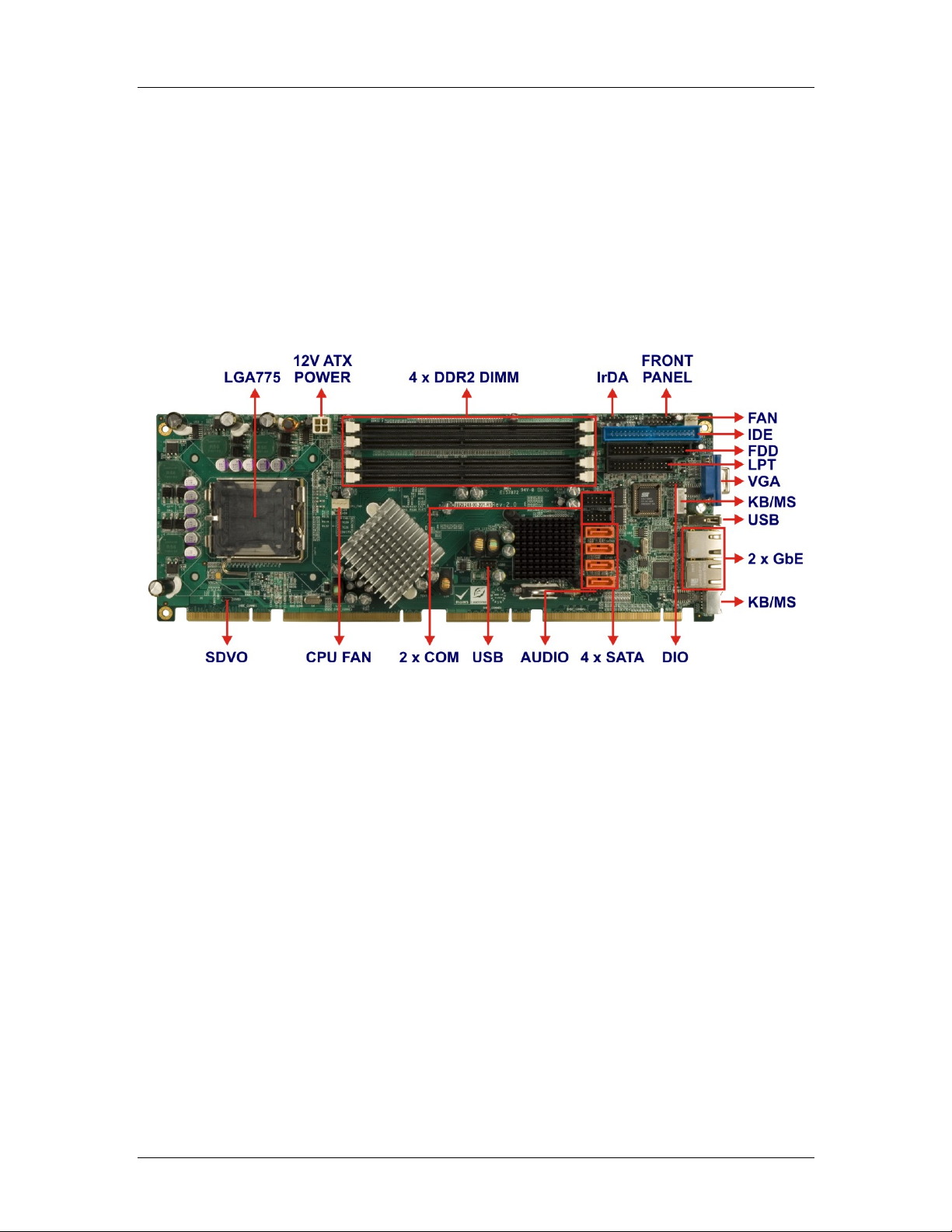
1.2.1 CEGA Overview Photo
The CEGA has a wide variety of internal and external peripheral connectors. The
peripheral connectors are connected to devices including storage devices, display devices
and parallel communications devices. A labeled photo of the peripheral connectors is
shown in Figure 1-1.
Figure 1-1: CEGA Overview
CyberResearch, Inc. 3
25 Business Park Drive P: (203) 483-8815; F: (203) 483-9024
Branford, CT USA www.cyberresearch.com
Page 24

CEGA Series CyberResearch® CPU Cards
1.2.2 CEGA Peripheral Connectors and Jumpers
The CEGA has the following connectors on-board:
1 x ATX 12V power connector
1 x Audio connector
4 x DIMM slots
1 x DIO connector
2 x Fan connectors
1 x Floppy disk connector
1 x Front panel connector
1 x IDE disk drive connector
1 x Infrared interface connector
1 x Keyboard connector
1 x Parallel port connector
1 x SDVO connector
4 x Serial ATA (SATA) drive connectors
2 x Serial port connectors
2 x USB connectors (8-pin header)
The CEGA has the following external peripheral interface connectors on the board rear
panel:
1 x PS/2 keyboard/mouse connector
2 x Ethernet connectors
1 x USB 2.0 connector
1 x VGA connector
The CEGA has the following on-board jumper:
Clear CMOS
4 ©Copyright 2007 CyberResearch, Inc
Page 25
CyberResearch® CPU Cards CEGA Series
1.2.3 Technical Specifications
CEGA technical specifications are listed below. Detailed descriptions of each specification
can be found in Chapter 2.
Product T ype CPU card (SBC)
LAN
Gigabit LAN
Video
USB
Backplane Filter Features
USB 2.0
RAID
Audio
SATA
Dual Gigabit LAN
Processor
Processor Type (CPU) Included Intel Pentium D
Supports dual-core
Dual-Core Processor Support
processors
Number of Processors/CPU Sockets Single CPU
CPU Socket Type Socket 775 (775 pins)
Processor Speed 3.6/3.2/2.4GHz
Processor FSB 800MHz
533MHz
FSB (CPU Front Side Bus Speed)
800MHz
1066MHz
Chipset Manufacturer Intel
Chipset Intel 945G / ICH7
Memory
Memory Maximum 3GB
System Memory
4 x 240-pin DDR2
Memory Sockets
DIMMs
CyberResearch, Inc. 5
25 Business Park Drive P: (203) 483-8815; F: (203) 483-9024
Branford, CT USA www.cyberresearch.com
Page 26

CEGA Series CyberResearch® CPU Cards
System Details
Card Form Factor
Full-length standard card
(7.5 to 13.4")
Standard Filter Card Length Full-length (7.5" to 13.4")
System Bus PICMG 1.3
BIOS Manufacturer AMI
BIOS
BIOS Chip Type Flash ROM
On-board real-time clock
Real-Time Clock (RTC)
(RTC)
On-Board V ideo
Video Chipset Built into system chipset
Video Output
Analog VGA (standard for
Analog
Signals
CRT or flat-panel)
Resolution, max. 2048 x 1536 pixels
HD15 (standard VGA)
Video Output Connectors
connector
On-Board I/O
I/O Controller Winbond W83627THG
Dual Broadcom BCM5787
Ethernet Controller Type
10/100/1000Base-T
(Gigabit)
2 x Gigabit
Channels
(10/100/1000Base-T)
LAN
On-Board LAN
Gigabit LAN
Ethernet Filter Config
Ethernet
Dual LAN
Dual Gigabit LAN
2 x RJ-45
Connector(s)
2 LEDs indicate LAN
access and link status
Wake-on-LAN Yes
Serial Ports UART/Controller Type 16550-compatible
6 ©Copyright 2007 CyberResearch, Inc
Page 27

CyberResearch® CPU Cards CEGA Series
Number of RS-232 Serial
Ports
Serial (COM)
Ports: RS-232
RS-232 Signals Supported
USB Ports, Total Qty.
2
TXD (TD, TX)
Transmitted Data
RXD (RD, RX) Received
Data
RTS : Request to Send
CTS : Clear to Send
DCD (CD) Data Carrier
Detect
DSR : Data Set Ready
DTR : Data Terminal
Ready
RI : Ring Indicator
GND : Signal Ground
3 on card; total of 7
supported (see below)
USB Ports
Parallel Ports
USB 2.0 Ports (480Mbps) 7
1 standard female USB
socket (Type A /
rectangular);
Header(s) on card for 2
USB Connectors
USB ports;
4 ports supported via PCI
Express x 16 signaling and
compatible backplanes
Parallel Ports, Total Qty. 1
ECP (Extended Capability
Port, bidirectional)
EPP (Enhanced Parallel
Parallel Port Modes Supported
Port, bidirectional)
SPP (Standard Parallel
Port)
Connector Type 26-pin male header on
CyberResearch, Inc. 7
25 Business Park Drive P: (203) 483-8815; F: (203) 483-9024
Branford, CT USA www.cyberresearch.com
Page 28

CEGA Series CyberResearch® CPU Cards
card
Floppy Drive
Ports
EIDE (hard
drive) Ports
SATA (hard
drive) Ports
RAID
Number of Drives Supported
1 FDD port - supports up
to 2 floppy drives
Connector Type 34-pin male header
Up to 2 hard drives /
Number of Drives/Devices Supported
devices
Ultra AT A/100 (A T A/100,
EIDE Interface Type
ATA-6) 100MB/sec
Connector(s) 40-pin male header
Number of Drives/Devices Supported Up to 4 SATA drives
SATA 3Gb/s (SATA/300,
SATA Interface Type
Serial AT A II)
Connector(s) 4 x 7-pin SATA (male)
RAID Support Yes
RAID T ype SATA (Serial ATA)
0
0 + 1 (RAID 10)
Disk Arrays Supported
1
IrDA (infrared)
Port
Digital I/O
5
SIR (serial infrared)
IrDA Types Supported
ASKIR (amplitude shift
keyed infrared)
Header for IrDA (infrared)
IrDA Connector
port
Number of I/O Lines 8
4 inputs
Configuration
4 outputs
DIO lines via 10-pin
Features
2.0mm header on card
8 ©Copyright 2007 CyberResearch, Inc
Page 29

CyberResearch® CPU Cards CEGA Series
Other Connectors
1xPS/2 (6-pin mini-DIN
Keyboard Connector(s)
female) with "Y" cable for
keybd. & mouse
PS/2 (6-pin mini-DIN
Pointing Device Connector
female, shared with
keyboard conn.)
4-pin auxiliary 12V
External Power Input Connector
connector
Audio
Audio Support (on-board) 5+1 surround sound output
AC'97
Audio Codec Supported
Realtek ALC655 (5.1-ch,
AC'97 rev2.3 compliant)
Buzzer or Speaker Buzzer for alarms
System Monitoring
Watchdog Timer Yes
1 to 255 seconds in
Watchdog Time-Out Intervals
1-second intervals
Power Consumption
+5VDC 2.6A
+12VDC 9A
-12VDC 100mA
+3.3VDC 6.3A
+5Vsb 930mA
LGA775-based card
requires an ATX12V-rated
Power Supply Notes
power supply to ensure
sufficient +12V power
Cooling
Fan for Processor (CPU Fan) 1 included
CyberResearch, Inc. 9
25 Business Park Drive P: (203) 483-8815; F: (203) 483-9024
Branford, CT USA www.cyberresearch.com
Page 30

CEGA Series CyberResearch® CPU Cards
Environmental Specifications
Operating Temperature 32°F....140°F (0°C....60°C)
Relative Humidity, noncondensing 5%....95%
Dimensions
CPU Card Length 13.32" (338.44mm)
CPU Card Height 4.97" (126.21mm)
Card Thickness (w/o CPU or RAM) 1.56" (39.73mm)
Weight
Weight 1.16lbs (526.17g )
10 ©Copyright 2007 CyberResearch, Inc
Page 31

CyberResearch® CPU Cards CEGA Series
0 0
Chapter
2
2 Detailed Specifications
CyberResearch, Inc. 11
25 Business Park Drive P: (203) 483-8815; F: (203) 483-9024
Branford, CT USA www.cyberresearch.com
Page 32

CEGA Series CyberResearch® CPU Cards
2.1 Overview
This chapter describes the specifications and on-board features of the CEGA in detail.
2.2 Dimensions
2.2.1 Board Dimensions
The dimensions of the board are listed below and shown in Figure 2-1.
Length: 338.58mm
Width: 126.39mm
Figure 2-1: CEGA Dimensions (mm)
12 ©Copyright 2007 CyberResearch, Inc
Page 33
CyberResearch® CPU Cards CEGA Series
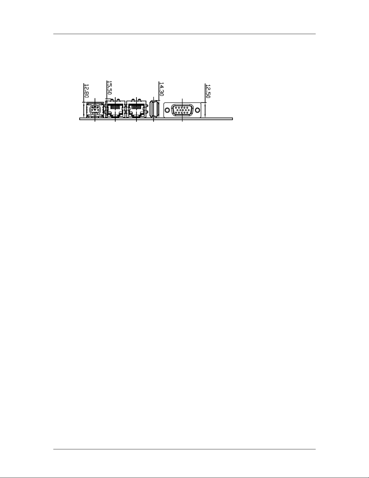
2.2.2 External Interface Panel Dimensions
External peripheral interface connector panel dimensions are shown in Figure 2-2.
Figure 2-2: External Interface Panel Dimensions (mm)
CyberResearch, Inc. 13
25 Business Park Drive P: (203) 483-8815; F: (203) 483-9024
Branford, CT USA www.cyberresearch.com
Page 34

CEGA Series CyberResearch® CPU Cards
2.3 Data Flow
Figure 2-3 shows the data flow between the two on-board chipsets and other components
installed on the backplane and described in the following sections of this chapter.
Figure 2-3: Data Flow Block Diagram
14 ©Copyright 2007 CyberResearch, Inc
Page 35
CyberResearch® CPU Cards CEGA Series
2.4 Compatible Processors
2.4.1 CPU Overview
Socket LGA 775 Intel® Core™ 2 Duo, Pentium® 4, Pentium® D and Celeron® D
processors can be installed on the CEGA CPU card. The
Celeron
®
D processors all have Extended Memory 64 Technology (EMT64T)
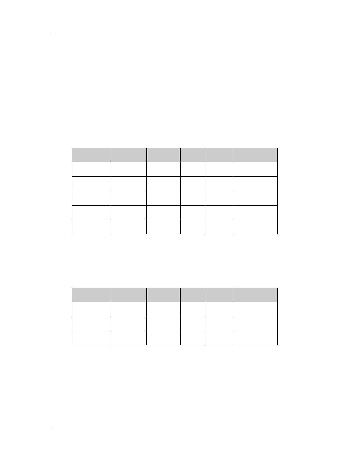
2.4.2 Supported Intel® Core™ 2 Duo Processors
Specifications for the compatible Intel® Core™ 2 Duo processors are listed in Table 2-1.
CPU Speed Bus Speed Mfg. Tech Cache Package Processor No.
2.66 GHz 1066 MHz 65 nm 4 MB LGA 775 E6700
2.40 GHz 1066 MHz 65 nm 4 MB LGA 775 E6600
®
Pentium® 4 processors and the
2.13 GHz 1066 MHz 65 nm 2 MB LGA 775 E6400
1.86 GHz 1066 MHz 65 nm 2 MB LGA 775 E6300
1.80 GHz 800 MHz 65 nm 2 MB LGA 775 E4300
Table 2-1: Supported Intel® Core™ 2 Duo Processors
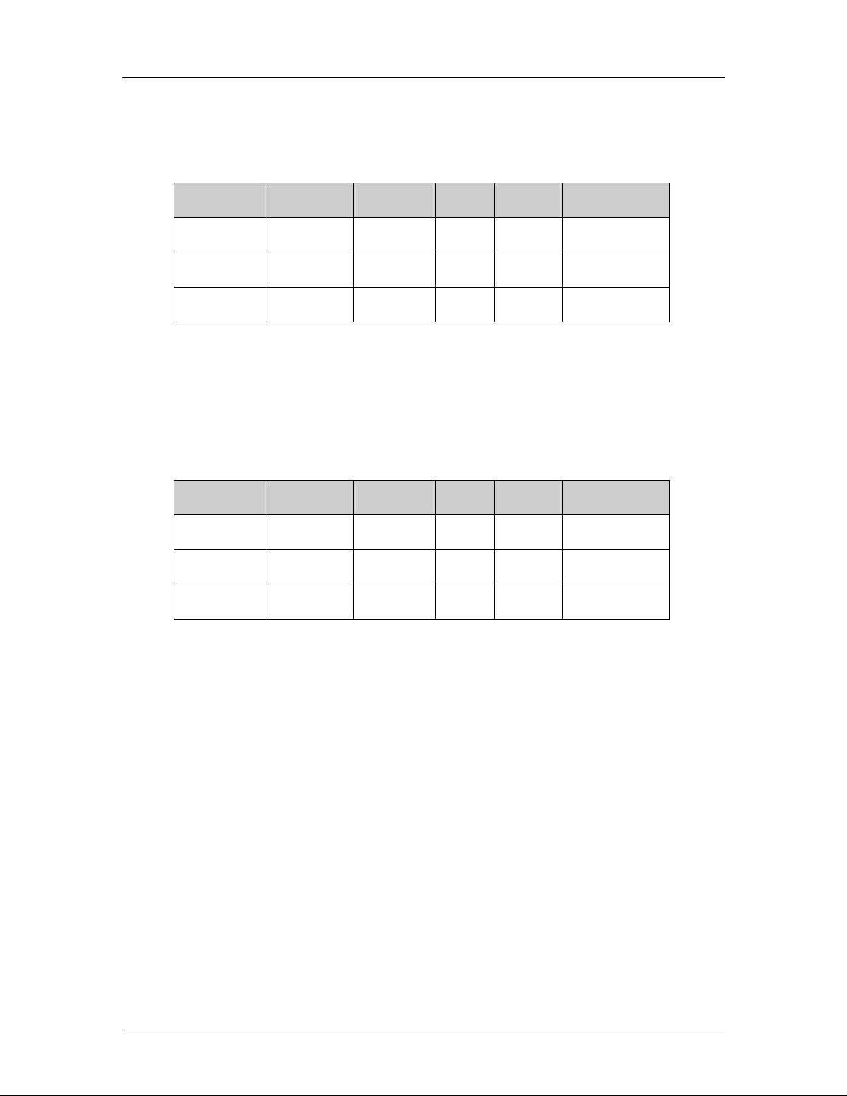
2.4.3 Supported Intel® Pentium® 4 Processors
Specifications for the compatible Intel® Pentium® 4 processors are listed in Table 2-2.
CPU Speed Bus Speed Mfg. Tech Cache Package Processor No.
3.80 GHz 800 MHz 90 nm 2 MB LGA 775 672
3.80 GHz 800 MHz 90 nm 1 MB LGA 775 570J
3.80 GHz 800 MHz 90 nm 1 MB LGA 775 571
Table 2-2: Supported Intel® Pentium® 4 Processors
CyberResearch, Inc. 15
25 Business Park Drive P: (203) 483-8815; F: (203) 483-9024
Branford, CT USA www.cyberresearch.com
Page 36
CEGA Series CyberResearch® CPU Cards
2.4.4 Supported Intel® Pentium® D Processors
Specifications for the compatible Intel® Pentium® D processors are listed in Table 2-3.
CPU Speed Bus Speed Mfg. Tech Cache Package Processor No.
3.60 GHz 800 MHz 65 nm 4 MB LGA 775 960
3.40 GHz 800 MHz 65 nm 4 MB LGA 775 950
3.40 GHz 800 MHz 65 nm 4 MB LGA 775 945
Table 2-3: Supported Intel® Pentium® D Processors
2.4.5 Supported Intel® Celeron® D Processors
Specifications for the compatible Intel® Celeron® D processors are listed in Table 2-4
below:
CPU Speed Bus Speed Mfg. Tech Cache Package Processor No.
3.60 GHz 533 MHz 65 nm 512 KB LGA 775 365
3.46 GHz 533 MHz 65 nm 512 KB LGA 775 360
3.33 GHz 533 MHz 65 nm 512 KB LGA 775 356
Table 2-4: Supported Intel® Celeron® D Processors
2.5 Intel® 945G Northbridge Chipset
2.5.1 Intel® 945G Overview
The Intel® 945G northbridge chipset consists of a graphics and memory controller hub
(GMCH). The GMCH on the Intel
(ICH7R) through a high speed Direct Media Interface (DMI) chip-to-chip connection. The
high-speed DMI integrates priority based servicing that allows for concurrent traffic and
true isochronous transfer capabilities. Some of the features of the Intel
®
945G is interfaced to the Intel® I/O Controller Hub 7
®
945G are listed
below.
Support 533/800/1066MHz FSB
Supports four, 1GB, 400/533/667MHz dual channel DDR SDRAM DIMMs
16 ©Copyright 2007 CyberResearch, Inc
Page 37
CyberResearch® CPU Cards CEGA Series
Integrated VGA and SDVO (Serial Digital Video Output) outputs
Integrated Intel
2.0GB/s concurrent DMI bandwidth maximizes chip set communications
PCI Express x16 Graphics Interface with a raw bit rate on data pins of 2Gb/s
Integrated Intel® High Definition Audio
Integrated Intel® Matrix Storage Technology
Integrated Intel® Active Management Technology
Integrated Intel® Flex Memory Technology
®
Graphics Media Accelerator 950 (Intel® GMA 950)
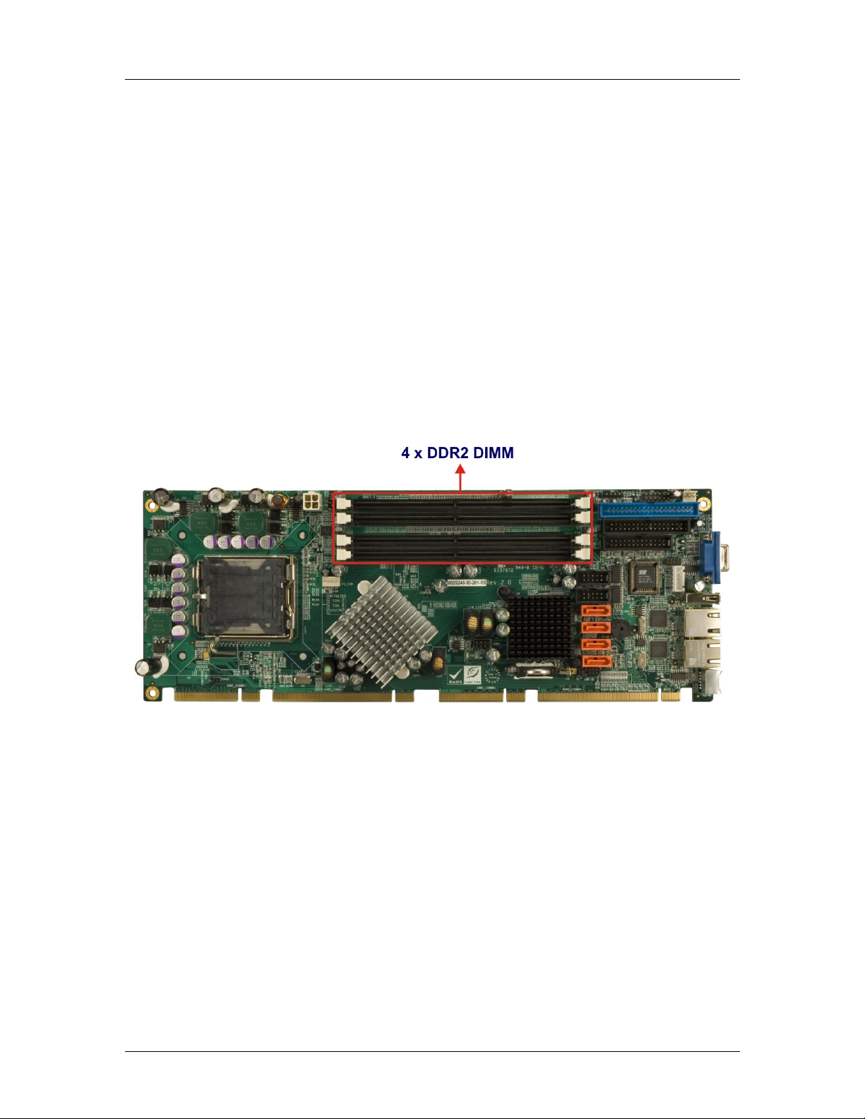
2.5.2 Intel® 945G Memory Support
The Intel® 945G supports four, 1GB, 400/533/667MHz dual channel DDR SDRAM DIMMs.
Four 240-pin memory sockets on the CEGA enable a maximum of 4GB of memory to be
installed on the system. The memory sockets are shown in Figure 2-4.
Figure 2-4: 240-pin DIMM Sockets
2.5.3 Intel® 945G Serial Digital Video Output (SDVO)
Some of the features of the SDVO ports are listed below.
Two SDVO ports multiplexed with PCI Express graphics interface
200 MHz dot clock on each 12-bit interface
Can combine two channels to form one larger interface
Flat panels up to 2048x1536 @ 60 Hz or digital CR T/HDTV at 1920x1080 @
85Hz
Dual independent display options with digital display
Multiplexed digital display channels (Supported with ADD2 Card).
CyberResearch, Inc. 17
25 Business Park Drive P: (203) 483-8815; F: (203) 483-9024
Branford, CT USA www.cyberresearch.com
Page 38

CEGA Series CyberResearch® CPU Cards
ADD2/ADD2+ card uses PCI Express graphics x16 connector
2.5.4 Intel® 945G Integrated Graphics Media Accelerator 950
The Intel® 945G has the Intel® GMA 950 integrated into the chipset. Some of the features
of the GMA 950 are listed below.
Intel GMA 950 Grap hics Core
o 400MHz 256-bit graphics core
o Up to 10.6 GB/sec memory bandwidth with DDR2 667 MHz system
memory
o 1.6 GPixels/sec and 1.6 GTexels/sec fill rate
o 192 MB maximum video memory
o 2048x1536 at 75 Hz maximum resolution
o Dynamic Display Modes for flat-panel, wide-screen and Digital TV support
o Operating systems supported: Microsoft Windows* XP, Windows* XP
64-bit, Media Center Edition, Windows 2000; Linux-compatible (Xfree86
source available)
High Performance 3D
o Up to 4 pixels per clock rendering
o Microsoft* DirectX* 9 Hardware Acceleration Features: Pixel Shader 2,
Volumetric Textures, Shadow Maps, Slope Scale Depth Bias, Two-Sided
Stencil
o Microsoft* DirectX* 9 Vertex Shader 3.0 and Transform and Lighting
supported in SW through highly optimized Processor Specific Geometry
Pipeline (PSGP)
o Texture Decompression for DirectX* and OpenGL*
o OpenGL* 1.4 support with ARB extensions
Advanced Display Technology
o Consumer Electronic display (Digital TV) support
o Two Serial Digital Video Out (SDVO) ports for flat-panel monitors via
ADD2 cards
o Multiple display types (LVDS, DVI-I, DVI-D, CRT)
o Dual screen support via ADD2 digital video devices
o HDTV 720p and 1080i display resolution support
o Interlaced Display output support
High Quality Media Support
18 ©Copyright 2007 CyberResearch, Inc
Page 39

CyberResearch® CPU Cards CEGA Series
o High Definition Hardware Motion Compensation to support HD hi-bitrate
MPEG2 media playback
o Up and Down Scaling of Video Content
o HD Content Decode – up to two stream support
o 5x3 Overlay Filtering
2.6 Intel® ICH7R Southbridge Chipset
2.6.1 Intel® ICH7R Overview
The ICH7R southbridge chipset on the CEGA has the features are listed below.
Complies with PCI Express Base Specification, Revision 1.0a
Complies with PCI Local Bus Spe cificati on, Revision 2.3 and su pports 33MHz
PCI operations
Supports ACPI Power Management Logic
Contains:
o Enhanced DMA controller
o Interrupt controller
o Timer functions
Integrated SATA host controller with DMA operations on four ports with data
transfer rates up to 3.0 Gb/s
Integrated IDE controller supports Ultra ATA 100/66/33
Supports eight USB 2.0 devices with four UHCI controllers and one EHCI
controller
Complies with System Management Bus (SMBus) Specification, Version 2.0
Supports Audio Codec ’97 (AC’97) Revision 2.3
Supports Intel
Contains Low Pin Count (LPC) interface
Supports Firmware Hub (FWH) interface
Serial Peripheral Interface (SPI) for Serial and Shared Flash
1.05 V Core Voltage
Intel® High Definition Audio Interface
Intel® Active Management T echnology
Intel® Quick Resume Technology Support
®
High Definition Audio
CyberResearch, Inc. 19
25 Business Park Drive P: (203) 483-8815; F: (203) 483-9024
Branford, CT USA www.cyberresearch.com
Page 40
CEGA Series CyberResearch® CPU Cards
2.6.2 Intel® ICH7R Audio Codec ’97 Controller
The Audio Codec ’97 (AC’97) controller integrated into the ICH7R complies with AC’97
Component Specification, Version 2.3. The AC’97 controller is connected to the onboard
audio connector. The audio connector is connected to an optional 5.1 channel or 7.1
channel audio kit with an embedded AC’97 audio codec. The A C’97 controlle r supports u p
to six PCM audio output channels. Complete surround sound requires six-channel audio
consisting of:
Front left
Front right
Back left
Back right
Center
Subwoofer
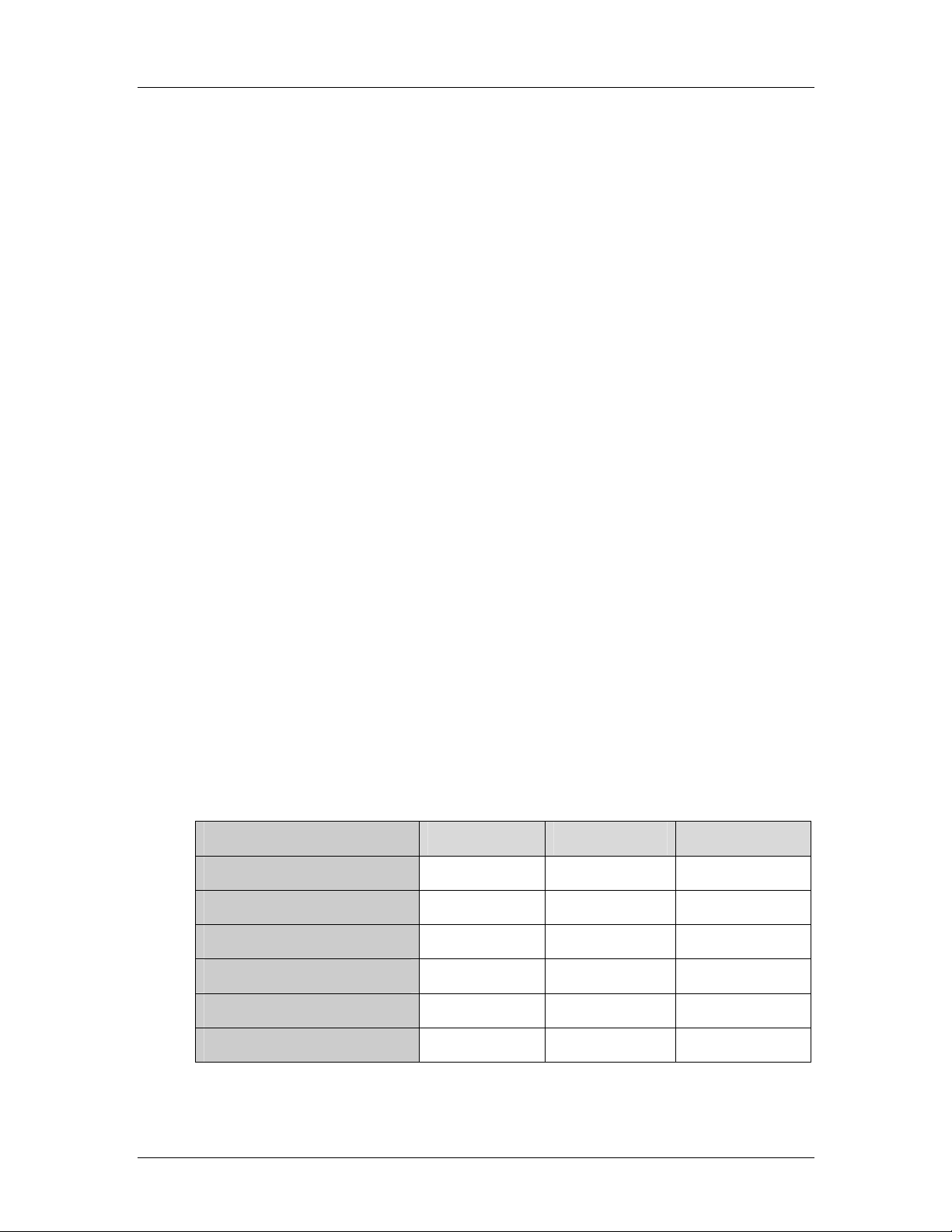
2.6.3 Intel® ICH7R IDE Interface
The integrated IDE interface on the ICH7R southbridge supports two IDE hard disks and
ATAPI devices, PIO IDE transfers up to 16MB/s and Ultra ATA transfers of 100MB/s. The
integrated IDE interface is able to support the following IDE HDDs:
Ultra A T A/10 0, with data transfer rates up to 100MB/s
Ultra A T A/66, with data transfer rates up to 66MB/s
Ultra A T A/33, with data transfer rates up to 33MB/s
Table 2-5 shows the supported HDD specifications.
Specification Ultra ATA/100 Ultra ATA/66 Ultra ATA/33
IDE devices 2 2 2
PIO Mode 0 – 4 0 – 4 0 – 4
PIO Max Transfer Rate 16.6 MB/s 16.6 MB/s 16.6 MB/s
DMA/UDMA designation UDMA 3 - 4 UDMA 3 – 4 UDMA 2
DMA/UDMA Max Transfer 100MB/s 66M B/s 33MB/s
Controller Interface 5V 5V 5V
20 ©Copyright 2007 CyberResearch, Inc
Page 41

CyberResearch® CPU Cards CEGA Series
Specification Ultra ATA/100 Ultra ATA/66 Ultra ATA/33
Table 2-5: Supported HDD Specifications
CyberResearch, Inc. 21
25 Business Park Drive P: (203) 483-8815; F: (203) 483-9024
Branford, CT USA www.cyberresearch.com
Page 42

CEGA Series CyberResearch® CPU Cards
2.6.4 Intel® ICH7R Low Pin Count (LPC) Interface
The ICH7R LPC interface complies with the LPC 1.1 specifications. The LPC bus from the
ICH7R is connected to the following components:
BIOS chipset
Super I/O chipset
2.6.5 Intel® ICH7R PCI Interface
The PCI interface on the ICH7R is compliant with the PCI Revision 2.3 implementation.
Some of the features of the PCI interface are listed below.
PCI Revision 2.3 compliant
33MHz
5V tolerant PCI signals (except PME#)
Integrated PCI arbiter supports up to seven PCI bus masters
Three of the seven PCI bus masters are interfaces to the following onboard components:
PCI slot connector on the bottom of the CPU card
Broadcom PCI Express GbE interface
Winbond PCI-to-ISA bridge interface
The remaining four PCI bus masters are reserved for four PCI expansion boards that can
be installed on the backplane.
22 ©Copyright 2007 CyberResearch, Inc
Page 43

CyberResearch® CPU Cards CEGA Series
2.6.6 ® ICH7R Real Time Clock
256 bytes of battery backed RAM is provided by the Motorola MC146818A real time clock
(RTC) integrated into the ICH7R. The RTC operates on a 3V battery and 32.768KHz
crystal. The RTC keeps track of the time and stores system data even when the system is
turned off.
2.6.7 Intel® ICH7R SATA Controller
The integrated SATA controller on the ICH7R southbridge supports four SATA drives with
independent DMA operations. SATA controller specifications are listed below.
Supports four SATA drives
Supports 3.0Gb/s data transfer spe eds
Supports Serial ATA Spe cification, Revision 1.0a and supports several
optional sections of the Serial ATA II: Extensions to Serial ATA 1.0
Specification, Revision 1.0 (AHCI sup port is required for some elements).
2.6.8 Intel® ICH7R USB Controller
Up to eight high-speed, full-speed or low-speed USB devices are supported by the ICH7R.
High-speed USB 2.0, with data transfers of up to 480MB/s, is enabled with the ICH7R
integrated Enhanced Host Controller Interface (EHCI) compliant host controller. USB
full-speed and low-speed signaling is supported by the four ICH7R integrated Universal
Host Controller Interface (UHCI) controller.
2.7 PCI Bus Components
2.7.1 PCI Bus Overview
The PCI bus controller on the ICH7R southbridge is compliant with PCI Revision 2.3
specifications and has a 33MHz PCI clock. The components listed below are all
connected to the PCI bus:
PCI Express slot connector on the bottom of the CPU card
Broadcom PCI Express GbE interface
Winbond PCI-to-ISA bridge interface
2.7.2 PCI Express (PCIe) Slot Connector
CyberResearch, Inc. 23
25 Business Park Drive P: (203) 483-8815; F: (203) 483-9024
Branford, CT USA www.cyberresearch.com
Page 44

CEGA Series CyberResearch® CPU Cards
The PCIe slot connector (Figure 2-5) is located on the bottom of the CPU card and
connects to a PCIe slot on a backplane.
Figure 2-5: PCIe Slot Connector
PCIe expansion cards installed on the backplane communicate with the system through
the PCIe connector.
2.7.3 Broadcom PCIe GbE interface
The BCM5787M Broadcom PCIe GbE controller is a 10/100/1000BASE-T Ethernet LAN
controller with triple-speed IEEE 802.3 compliant MAC, triple-speed Ethernet transceiver,
a PCIe bus interface, and on-chip buffer memory:
Integrated 10/100/1000BASE-T transceiver
Automatic MDI crossover function
PCIe v1.0a
10/100/1000BASE-T full/half-duplex MAC
Wake on LAN support meeting the ACPI requirements
Statistics for SNMP MIB II, Ethernet-like MIB, and Ethernet MIB (802.3z,
clause 30)
Serial EEPROM or serial flash support
JT A G sup po rt
24 ©Copyright 2007 CyberResearch, Inc
Page 45

CyberResearch® CPU Cards CEGA Series
2.8 LPC Bus Components
2.8.1 LPC Bus Overview
The LPC bus is connected to the BIOS chipset and SuperI/O chipset (on reverse side of
the card) shown in Figure 2-6.
Figure 2-6: LPC Bus Chipsets
2.8.2 BIOS Chipset
The BIOS chipset has a licensed copy of AMI BIOS installed on the chipset. Some of the
BIOS features are listed below:
AMI Flash BIOS
SMIBIOS (DMI) compliant
Console redirection function support
PXE (Pre-boot Execution Environment) support
USB booting support
2.8.3 Super I/O Chipset
The Winbond W83627THG Super I/O chipset is connected to the ICH7R southbridge
through the LPC bus. Some of the features of the Winbond W83627THG chipset are li sted
below.
LPC Interface
PC98/2001, ACPI and LANDesk Compliant
CyberResearch, Inc. 25
25 Business Park Drive P: (203) 483-8815; F: (203) 483-9024
Branford, CT USA www.cyberresearch.com
Page 46

CEGA Series CyberResearch® CPU Cards
Hardware Monitor
Fan Speed Controller
+5V, 5VSB and 3.3V Power Supply
Two 16C550 UARTs for serial port control
One IEEE 1284 Parallel Port
Floppy Disk Controller
Keyboard Controller
Watchdog T i mer
Serial IRQ Support
Some of the Super I/O features are described in more detail below.
2.8.3.1 Super I/O LPC Interface
The LPC interface on the Super I/O complies with the Intel® Low Pin Count Specification
Rev. 1.1. The LPC interface supports both LDRQ# and SERIRQ protocols as well as PCI
PME# interfaces.
2.8.3.2 Super I/O 16C550 UARTs
The onboard Super I/O has two integrated 16C550 UARTs that can support the following:
Two standard serial ports
IrDa 1.0 and ASKIR protocols
2.8.3.3 Super I/O Hardware Monitor
The Super I/O Hardware Monitor monitors three thermal inputs, VBAT internally, and eight
voltage monitor inputs. The Super I/O Hardware Monitor supports the SmartFan® control
system, including the “Thermal Cruise™” and “Speed Cruise™” functions. These
hardware parameters are reported in the BIOS and can be read from the BIOS Hardware
Health Configuration menu.
2.8.3.4 Super I/O Fan Speed Controller
The Super I/O fan speed controller enables the system to monitor the speed of the fan.
One of the pins on the fan connector is reserved for fan speed detection and interfaced to
the fan speed controller on the Super I/O. The fan speed is then reported in the BIOS.
26 ©Copyright 2007 CyberResearch, Inc
Page 47

CyberResearch® CPU Cards CEGA Series
2.8.3.5 Super I/O Floppy Disk Controller
The Super I/O floppy disk controller (FDC) supports the following 3-mode floppy disk
drives (FDD).
360KB
720KB
1.2MB
1.44MB
2.88MB
The FDC also supports automatic write protection through software.
2.8.3.6 Super I/O Parallel Port
The Super I/O parallel port (LPT) supports standard mode, enhanced mode and
high-speed mode parallel port devices. The LPT is compliant with the following LPT
modes.
Standard mode
o Bi-directional SPP compliant
Enhanced mode
o EPP v1.7 compliant
o EPP v1.9 compliant
High-speed mode
o ECP, IEEE 1284 compliant
2.8.3.7 Super I/O Keyboard Controller
The Super I/O keyboard controller can execute the 8042 instruction set. Some of the
keyboard controller features are listed below:
The 8042 instruction is compatible with a PS/2 keyboard and PS/2 mouse
Gate A20 and Keyboard re set output
Supports multiple keyboard power on events
Supports mouse double-click and/or mouse move power on events
2.9 Environmental and Power Specifications
2.9.1 System Monitoring
Three thermal inputs on the CEGA Super I/O Hardware Monitor the following
temperatures:
CyberResearch, Inc. 27
25 Business Park Drive P: (203) 483-8815; F: (203) 483-9024
Branford, CT USA www.cyberresearch.com
Page 48

CEGA Series CyberResearch® CPU Cards
System temperature
Power temperature
CPU temperature
The CEGA Super I/O Hardware Monitor the following voltages:
4 external voltage detect inputs
3 intrinsic voltage monitoring (typical for Vbat, +5VSB , +5VCC)
The CEGA Super I/O Hardware Monitor also monitors the following fan speeds:
CPU Fan speed
System Fan speed
Auxiliary Fan speed
The values for the above environmental parameters are all recorded in the BIOS
Hardware Health Configuration menu.
2.9.2 Operating Temperature and Temperature Control
The maximum and minimum operating temperatures for the CEGA are listed below.
Minimum Operating Temperature: 0ºC (32°F)
Maximum Operating Temperature: 60°C (140°F)
A cooling fan and heat sink must be installed on the CPU. Thermal paste must be
smeared on the lower side of the heat sink before it is mounted on the CPU. Heat sinks
are also mounted on the northbridge and southbridge chipsets to ensure the operating
temperature of these chips remain low.
28 ©Copyright 2007 CyberResearch, Inc
Page 49
CyberResearch® CPU Cards CEGA Series
2.9.3 Power Consumption
Table 2-6 shows the power consumption parameters for the CEGA when running with a
3.73GHz, Intel
memory.
Voltage Current
+3.3V 6.3A
+5V 2.6A
5VSB 0.93A
-12V 0.1A
+12V 9A
Table 2-6: Power Consumption
®
Pentium D processor with a 1066MHz FSB and 4GB of 667MHz DDR2
CyberResearch, Inc. 29
25 Business Park Drive P: (203) 483-8815; F: (203) 483-9024
Branford, CT USA www.cyberresearch.com
Page 50

CEGA Series CyberResearch® CPU Cards
0 0
Chapter
3
3 Unpacking
30 ©Copyright 2007 CyberResearch, Inc
Page 51
CyberResearch® CPU Cards CEGA Series
3.1 Anti-static Precautions
WARNING:
Failure to take ESD precautions during the installation of the CEGA
may result in permanent damage to the CEGA and severe injury to the
user.
Electrostatic discharge (ESD) can cause serious damage to electronic components,
including the CEGA. Dry climates are especially susceptible to ESD. It is critical that the
following anti-static precautions are strictly adhered to whenever handling the CEGA or
any other electrical component.
Wear an anti-static wristband - Wearing a simple anti-static wristband can
help to prevent ESD from damaging the CEGA.
Self-grounding - Touch a grounded conducting material before handling and
periodically while handling the CEGA.
Use an anti-static pad - When configuring the CEGA, place it on an
antic-static pad to reduce the possibility of ESD damage.
Only handle the edges of the CEGA - When handling the CEGA, hold it by
its edges.
3.2 Unpacking
3.2.1 Unpacking Precautions
When the CEGA is unpacked, please do the following:
Follow the anti-static precautions outlined in Section 3.1.
Make sure the packing box is facing upward s so the CEGA does not fall out of
the box.
Make sure all the components shown in Section 3.3 are present.
3.3 Unpacking Checklist
NOTE:
If any of the components listed in the checklist below are missing,
please do not proceed with the installation. Contact
CyberResearch, Inc. 31
25 Business Park Drive P: (203) 483-8815; F: (203) 483-9024
Branford, CT USA www.cyberresearch.com
Page 52
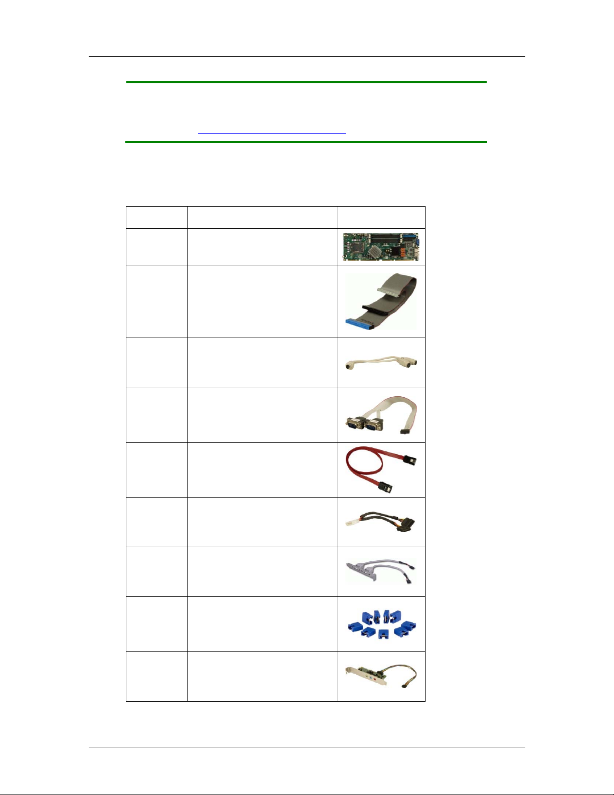
CEGA Series CyberResearch® CPU Cards
CYBERRESEARCH, INC. technical support. Call 203-483-8815 and
ask for technical support, fax 203-483-9024 attn: tech support, or
e-mail techsupport@cyberresearch.com
.
3.3.1 Package Contents
The CEGA is shipped with the following components:
Quantity Item and Part Number Image
1 CEGA
ATA 66/100 flat cable
1
KB/MS PS/2 Y-cable
1
Double RS-232 cable
1
4
2
1
1
1
SATA cables
SATA power cable
USB cable
Mini jumper Pack
5.1 Channel Audio Kit
32 ©Copyright 2007 CyberResearch, Inc
Page 53
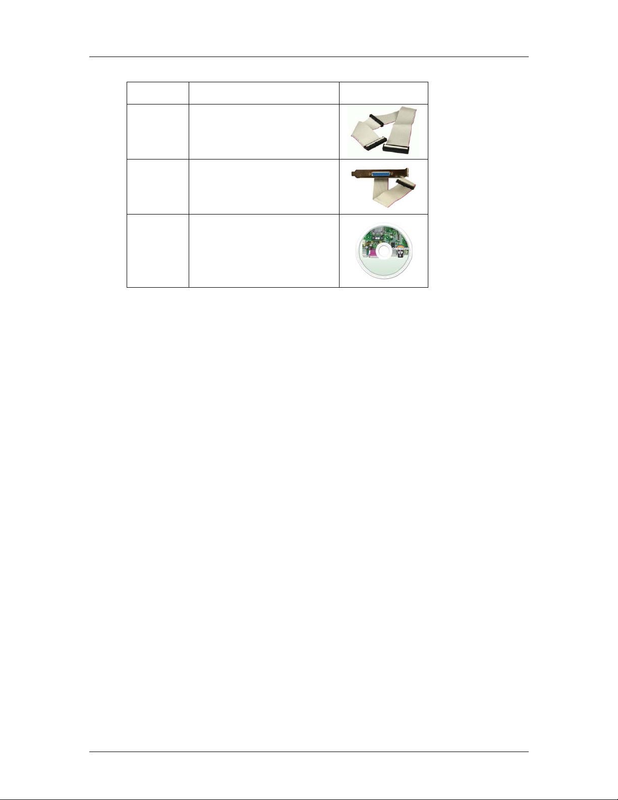
CyberResearch® CPU Cards CEGA Series
Quantity Item and Part Number Image
FDD cable
1
LPT cable
1
Utility CD
1
Table 3-1: Package List Contents
CyberResearch, Inc. 33
25 Business Park Drive P: (203) 483-8815; F: (203) 483-9024
Branford, CT USA www.cyberresearch.com
Page 54

CEGA Series CyberResearch® CPU Cards
0 0
Chapter
4
4 Connector Pinouts
34 ©Copyright 2007 CyberResearch, Inc
Page 55

CyberResearch® CPU Cards CEGA Series
4.1 Peripheral Interface Connectors
Section 4.1.2 shows peripheral interface connector locations. Section 4.1.2 lists all the
peripheral interface connectors seen in Section 4.1.2.
4.1.1 CEGA Layout
Figure 4-1 shows the on-board peripheral connectors, rear panel peripheral connectors
and on-board jumpers.
Figure 4-1: Connector and Jumper Locations
4.1.2 Peripheral Interface Connectors
Table 4-1 shows a list of the peripheral interface connectors on the CEGA. Detailed
descriptions of these connectors can be found below.
Connector Type Label
ATX power connector 4-pin header CPU12V1
Audio connector 10-pin header AUDIO1
Fan connector - CPU 3-pin wafer CPU_FAN
Fan connector - System 4-pin wafer FAN1
Floppy disk drive connector 34-pin box header FDD1
Front panel connector 12-pin header CN1
IDE Interface connector 40-pin box header IDE1
Infrared connector 5-pin header IR1
CyberResearch, Inc. 35
25 Business Park Drive P: (203) 483-8815; F: (203) 483-9024
Branford, CT USA www.cyberresearch.com
Page 56
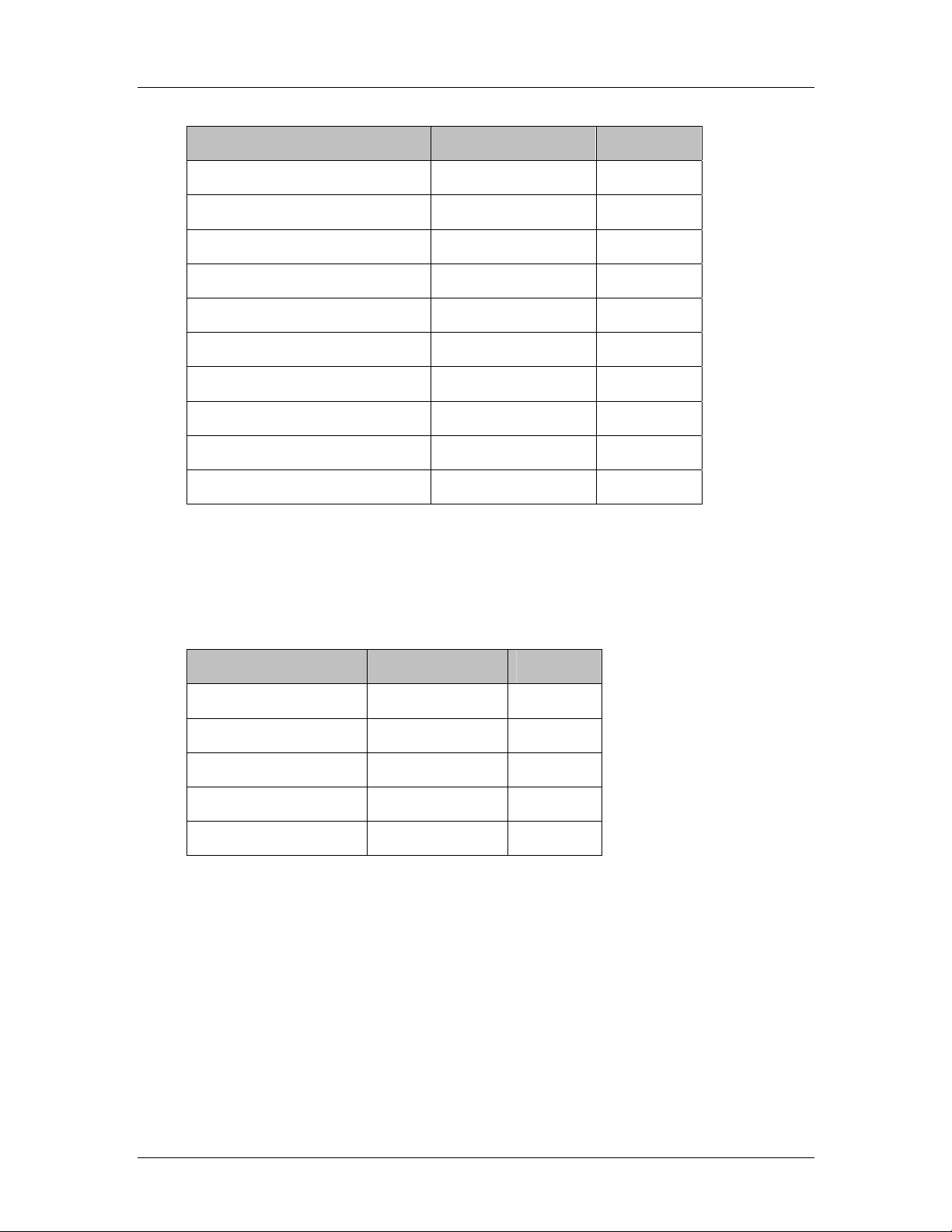
CEGA Series CyberResearch® CPU Cards
Connector Type Label
Keyboard connector 5-pin wafer CN2
Parallel port connector 26-pin box header LPT1
RS-232 serial port connector 10-pin box header COM1
RS-232 serial port connector 10-pin box header COM2
SATA drive connector 7-pin SATA SATA1
SATA drive connector 7-pin SATA SATA2
SATA drive connector 7-pin SATA SATA3
SATA drive connector 7-pin SATA SATA4
SDVO connector 3-pin header SDVO1
USB connector 8-pin header USB0
Table 4-1: Peripheral Interface Connectors
4.1.3 External Peripheral Interface Panel Connectors
Table 4-2 lists the external peripheral interface panel connectors on the CEGA.
Connector Type Label
Keyboard/Mouse PS/2 KB/MS
Ethernet connector RJ-45 LAN1
Ethernet connector RJ-45 LAN2
USB port connector USB port USB_C0
VGA port connector DB-15 (female) VGA1
Table 4-2: External Peripheral Interface Panel Connectors
4.2 Internal Peripheral Connectors
Internal peripheral connectors are found on the backplane and are only accessible when
the backplane is outside of the chassis. This section has complete descriptions of all the
internal, peripheral connectors on the CEGA.
36 ©Copyright 2007 CyberResearch, Inc
Page 57
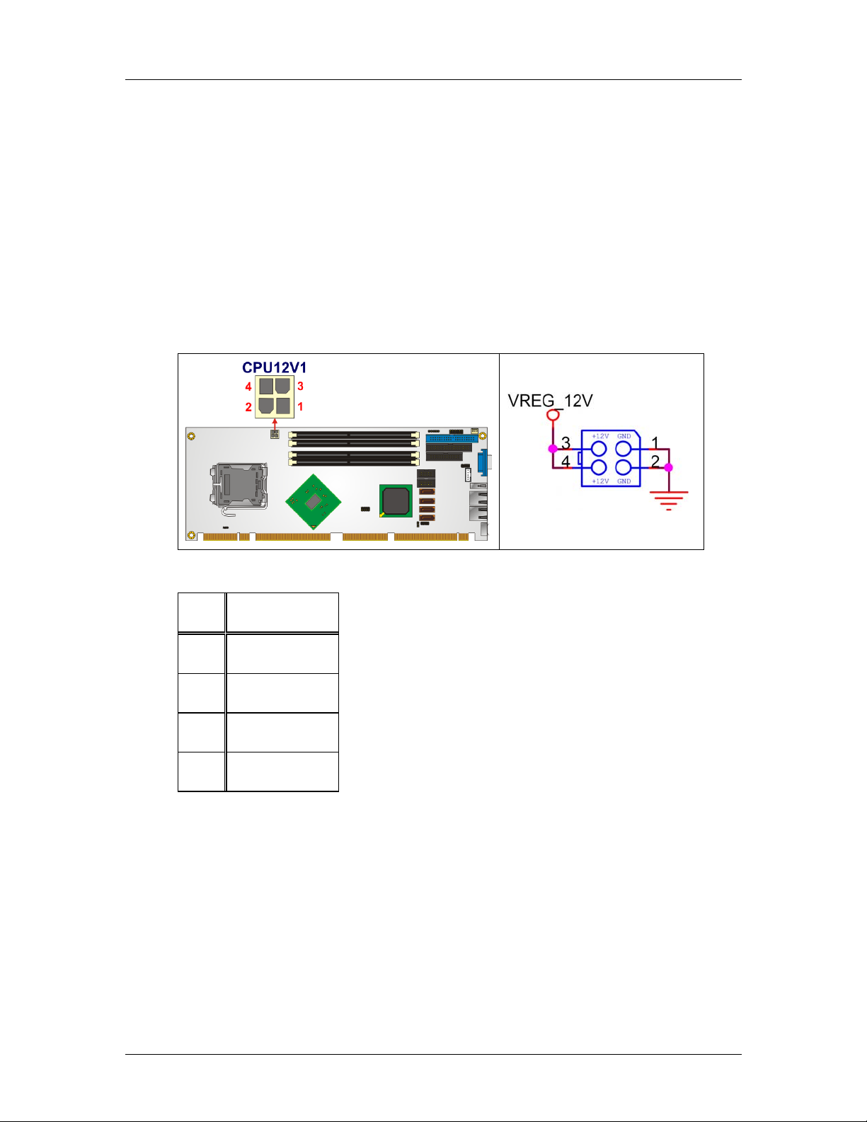
CyberResearch® CPU Cards CEGA Series
4.2.1 +12V ATX Power Supply Connector
CN Label:
CN Type:
CN Location:
CN Pinouts:
CPU12V1
4-pin ATX power connector (1x4)
See Figure 4-2
See Table 4-3
The 4-pin +12V ATX power supply connector is connected to a +12V ATX power supply.
Figure 4-2: +12V ATX Power Connector Location
PIN DESCRIPTION
1 GND
2 GND
3 +12V
4 +12V
Table 4-3: +12V ATX Power Connector Pinouts
CyberResearch, Inc. 37
25 Business Park Drive P: (203) 483-8815; F: (203) 483-9024
Branford, CT USA www.cyberresearch.com
Page 58

CEGA Series CyberResearch® CPU Cards
4.2.2 Audio Connector (10-pin)
CN Label:
CN Type:
CN Location:
CN Pinouts:
AUDIO1
10-pin header (2x5)
See Figure 4-3
See Table 4-4
The 10-pin audio connector is connected to external audio devices including speakers and
microphones for the input and output of audio signals to and from the system.
Figure 4-3: Audio Connector Location (10-pin)
PIN DESCRIPTION PIN DESCRIPTION
1 AC_SYNC 2 AC_CLK
3 AC_SDOUT 4 PC_BEEP
5 AC_SDIN 6 AC_RST#
7 PWR (+5V) 8 GND
9 PWR (+12V) 10 GND
38 ©Copyright 2007 CyberResearch, Inc
Page 59

CyberResearch® CPU Cards CEGA Series
Table 4-4: Audio Connector Pinouts (10-pin)
4.2.3 Digital Input/Output (DIO) Connector
CN Label:
CN Type:
CN Location:
CN Pinouts:
DIO1
10-pin header (2x5)
See Figure 4-4
See Table 4-5
The digital input/output connector is managed through a Super I/O chip. The DIO
connector pins are user programmable.
Figure 4-4: DIO Connector Locations
PIN DESCRIPTION PIN DESCRIPTION
1 GND 2 PWR (+5V)
3 XOUT0 4 XOUT1
5 XOUT3 6 XOUT4
7 XIN0 8 XIN1
9 XIN2 10 XIN3
Table 4-5: DIO Connector Pinouts
CyberResearch, Inc. 39
25 Business Park Drive P: (203) 483-8815; F: (203) 483-9024
Branford, CT USA www.cyberresearch.com
Page 60

CEGA Series CyberResearch® CPU Cards
4.2.4 Fan Connectors
CN Label:
CN Type:
CN Location:
CN Pinouts:
The CPU_FAN and FAN1 cooling fan connectors provide a 12V current to the cooling
fans. The connector has a "rotation" pin to get rotation signals from the fan and notify the
system so the system BIOS can recognize the fan speed. Please note that only certain
fans can issue the rotation signals.
CPU_FAN, FAN1
CPU_FAN: 4-pin wafer connector
FAN1: 3-pin wafer connector
See Figure 4-5
See Table 4-6
FAN1
CPU_FAN
Figure 4-5: Fan Connectors Locations
40 ©Copyright 2007 CyberResearch, Inc
Page 61

CyberResearch® CPU Cards CEGA Series
PIN CPU_FAN FAN1
1 GND GND
2 +12V +12V
3 Rotation Signal Rotation Signal
4 Control
Table 4-6: Fan Connectors Pinouts
4.2.5 Floppy Disk Connector (34-pin)
CN Label:
CN Type:
CN Location:
CN Pinouts:
FDD1
34-pin header (2x17)
See Figure 4-6
See Table 4-7
The floppy disk connector is connected to a floppy disk drive.
Figure 4-6: 34-pin FDD Connector Location
CyberResearch, Inc. 41
25 Business Park Drive P: (203) 483-8815; F: (203) 483-9024
Branford, CT USA www.cyberresearch.com
Page 62

CEGA Series CyberResearch® CPU Cards
PIN DESCRIPTION PIN DESCRIPTION
1 GND 2 REDUCE WRITE
3 GND 4 N/C
5 N/C 6 N/C
7 GND 8 INDEX#
9 GND 10 MOTOR ENABLE A#
11 GND 12 DRIVE SELECT B#
13 GND 14 DRIVE SELECT A#
15 GND 16 MOTOR ENABLE B#
17 GND 18 DIRECTION#
19 GND 20 STEP#
21 GND 22 WRITE DATA#
23 GND 24 WRITE GATE#
25 GND 26 TRACK 0#
27 GND 28 WRITE PROTECT#
29 GND 30 READ DATA#
31 GND 32 SIDE 1 SELECT#
33 GND 34 DISK CHANGE#
Table 4-7: 34-pin FDD Connector Pinouts
42 ©Copyright 2007 CyberResearch, Inc
Page 63

CyberResearch® CPU Cards CEGA Series
4.2.6 Front Panel Connector (12-pin)
CN Label: CN1
CN Type: 12-pin header (2x6)
CN Location: See Figure 4-7
CN Pinouts: See Table 4-8
The front panel connector connects to external switches and indicators that monitor and
control the backplane:
Power button
Reset button
Power LED
HDD LED
PC speaker
Figure 4-7: Front Panel Connector Pinout Locations
PIN DESCRIPTION PIN DESCRIPTION
1 PWR LED+ 2 PC_BEEP
3 PWR LED- 4 GND
5 PWR ON+ 6 NC
7 PWR ON- 8 PWR (+5V)
9 HDD LED+ 10 Reset+
11 HDD LED- 12 Reset-
Table 4-8: Front Panel Connector Pinouts
4.2.7 IDE Connector (40-pin)
CN Label:
IDE1
CyberResearch, Inc. 43
25 Business Park Drive P: (203) 483-8815; F: (203) 483-9024
Branford, CT USA www.cyberresearch.com
Page 64

CEGA Series CyberResearch® CPU Cards
CN Type:
CN Location:
CN Pinouts:
40-pin header (2x20)
See Figure 4-8
See Table 4-9
One 40-pin IDE device connector on the CEGA supports connectivity to two hard disk
drives.
Figure 4-8: IDE Device Connector Locations
PIN DESCRIPTION PIN DESCRIPTION
1 RESET# 2 GROUND
3 DATA 7 4 DATA 8
5 DATA 6 6 DATA 9
7 DATA 5 8 DATA 10
9 DATA 4 10 DATA 11
11 DATA 3 12 DATA 12
13 DATA 2 14 DATA 13
15 DATA 1 16 DATA 14
17 DATA 0 18 DATA 15
44 ©Copyright 2007 CyberResearch, Inc
Page 65
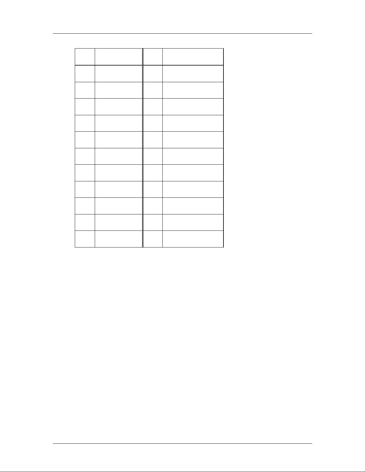
CyberResearch® CPU Cards CEGA Series
PIN DESCRIPTION PIN DESCRIPTION
19 GROUND 20 N/C
21 IDE DRQ 22 GROUND
23 IOW# 24 GROUND
25 IOR# 26 GROUND
27 IDE CHRDY 28 GROUND
29 IDE DACK 30 GROUND–DEFAULT
31 INTERRUPT 32 N/C
33 SA1 34 N/C
35 SA0 36 SA2
37 HDC CS0# 38 HDC CS1#
39 HDD ACTIVE# 40 GROUND
Table 4-9: IDE Connector Pinouts
4.2.8 Infrared Interface Connector (5-pin)
CN Label:
CN Type:
CN Location:
CN Pinouts:
IR1
5-pin header (1x5)
See Figure 4-9
See Table 4-10
The infrared interface connector supports both Serial Infrared (SIR) and Amplitude Shift
Key Infrared (ASKIR) interfaces.
CyberResearch, Inc. 45
25 Business Park Drive P: (203) 483-8815; F: (203) 483-9024
Branford, CT USA www.cyberresearch.com
Page 66

CEGA Series CyberResearch® CPU Cards
Figure 4-9: Infrared Connector Pinout Locations
PIN DESCRIPTION
1 VCC
2 NC
3 IR-RX
4 GND
5 IR-TX
Table 4-10: Infrared Connector Pinouts
4.2.9 Keyboard Connector
CN Label:
CN Type:
CN Location:
CN Pinouts:
KB1
5-pin header (1x5)
See Figure 4-10
See Table 4-11
The keyboard connector can be connected to a standard PS/2 cable or PS/2 cable to add
keyboard and mouse functionality to the system.
46 ©Copyright 2007 CyberResearch, Inc
Page 67

CyberResearch® CPU Cards CEGA Series
Figure 4-10: Keyboard Connector Location
PIN NO. DESCRIPTION
1 KEYBOARD CLOCK
2 KEYBOARD DATA
3 N/C
4 GROUND
5 VCC
Table 4-11: Keyboard Connector Pinouts
4.2.10 Parallel Port Connector
CN Label:
CN Type:
CN Location:
CN Pinouts:
The 26-pin parallel port connector connects to a parallel port connector interface or some
other parallel port device such as a printer.
LPT1
26-pin box header
See Figure 4-10
See Table 4-11
CyberResearch, Inc. 47
25 Business Park Drive P: (203) 483-8815; F: (203) 483-9024
Branford, CT USA www.cyberresearch.com
Page 68
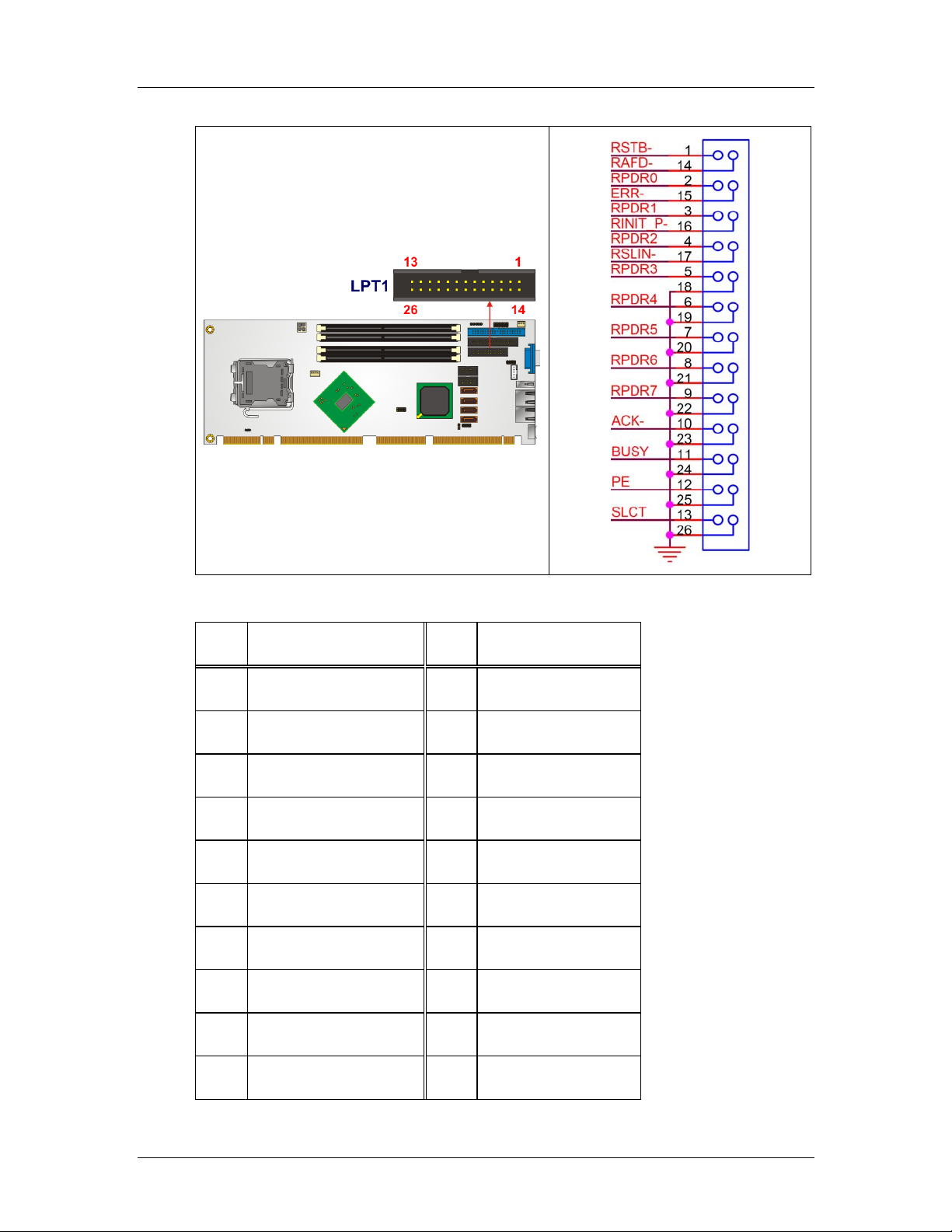
CEGA Series CyberResearch® CPU Cards
Figure 4-11: Parallel Port Connector Location
PIN DESCRIPTION PIN DESCRIPTION
1 STROBE# 2 DATA 0
3 DATA 1 4 DATA 2
5 DATA 3 6 DATA 4
7 DATA 5 8 DATA 6
9 DATA 7 10 ACKNOWLEDGE
11 BUSY 12 PAPER EMPTY
13 PRINTER SELECT 14 AU TO FORM FEED #
15 ERROR# 16 INITIALIZE
17 PRINTER SELECT LN# 18 GROUND
19 GROUND 20 GROUND
48 ©Copyright 2007 CyberResearch, Inc
Page 69
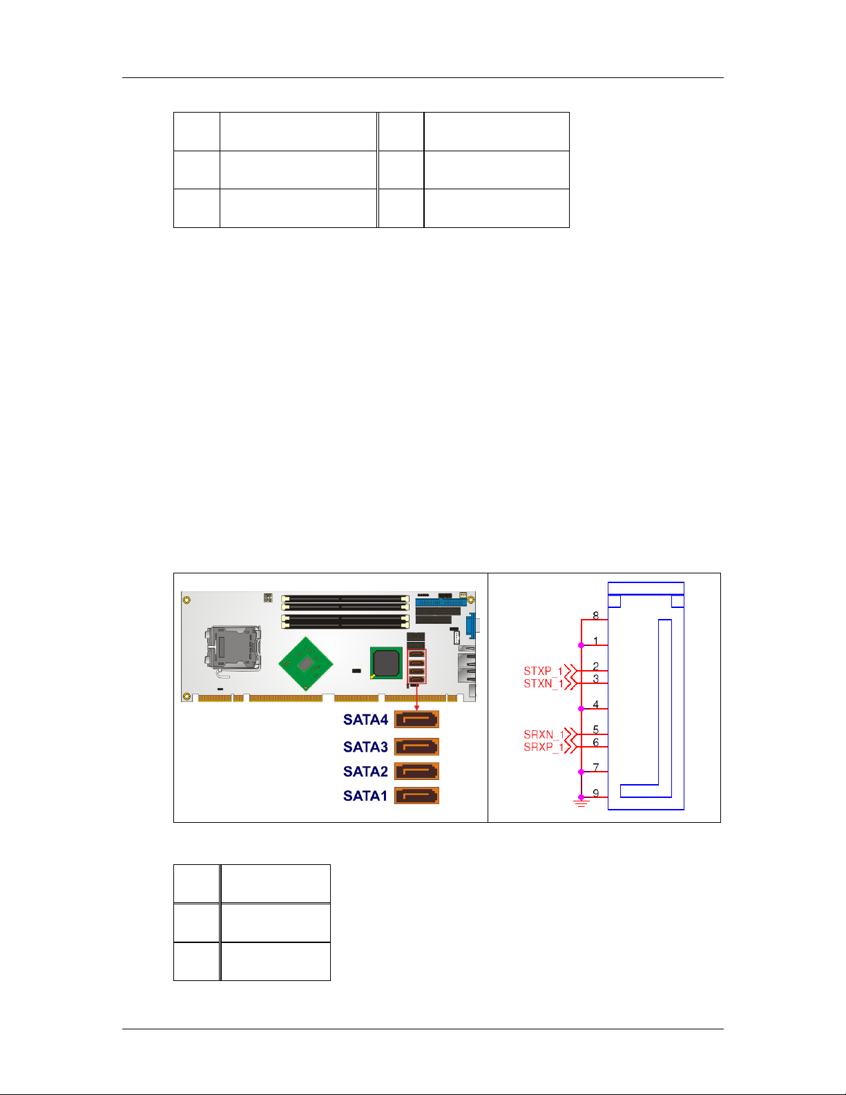
CyberResearch® CPU Cards CEGA Series
21 GROUND 22 GROUND
23 GROUND 24 GROUND
25 GROUND 26 NC
Table 4-12: Parallel Port Connector Pinouts
4.2.11 SATA Drive Connectors
CN Label:
CN Type:
CN Location:
CN Pinouts:
SATA1, SATA2, SATA3 and SATA4
7-pin SATA drive connectors
See Figure 4-11
See Table 4-12
The SATA drive connectors are connected to SATA 3Gb/s disk drives that transfer data at
speeds as high as 3.0Gb/s. The SATA drives can be configured in a RAID configuration.
Figure 4-12: SATA Drive Connector Locations
PIN DESCRIPTION
1 GND
2 TX+
CyberResearch, Inc. 49
25 Business Park Drive P: (203) 483-8815; F: (203) 483-9024
Branford, CT USA www.cyberresearch.com
Page 70

CEGA Series CyberResearch® CPU Cards
3 TX-
4 GND
5 RX-
6 RX+
7 GND
Table 4-13: SATA Drive Connector Pinouts
50 ©Copyright 2007 CyberResearch, Inc
Page 71
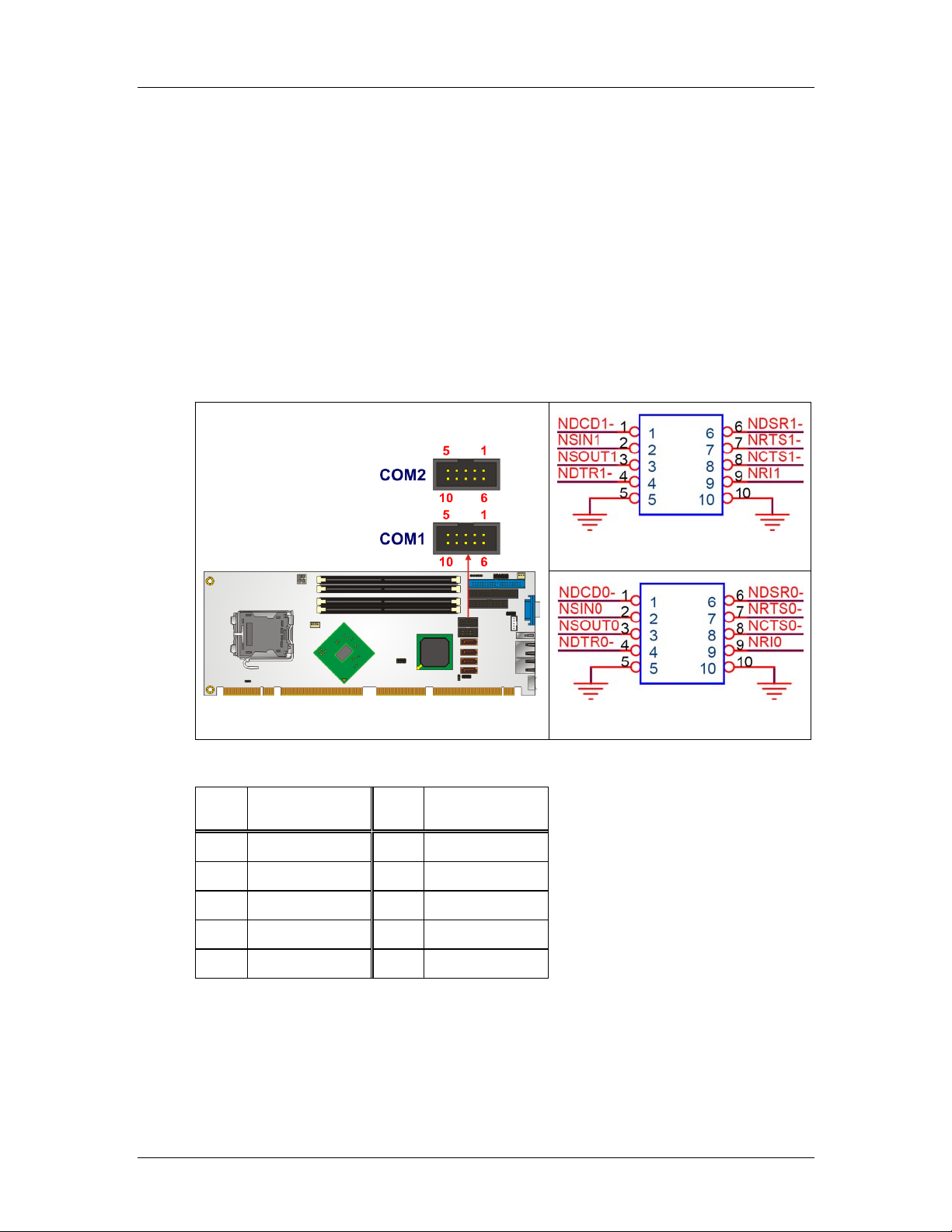
CyberResearch® CPU Cards CEGA Series
4.2.12 Serial Port Connector (COM1 and COM2)
CN Label:
CN Type:
CN Location:
CN Pinouts:
COM1 and COM2
10-pin header (2x5)
See Figure 4-12
See Table 4-13
The 10-pin serial port connectors provide RS-232 serial communications channels that
can be connected to external RS-232 serial port devices.
COM2
COM1
Figure 4-13: Serial Port Connector Pinout Locations
PIN DESCRIPTION PIN DESCRIPTION
1 DCD- 6 DSR-
2 SIN 7 RTS3 SOUT 8 CTS-
4 DTR- 9 RI
5 GND 10 GND
Table 4-14: Serial Port Connector Pinouts
CyberResearch, Inc. 51
25 Business Park Drive P: (203) 483-8815; F: (203) 483-9024
Branford, CT USA www.cyberresearch.com
Page 72
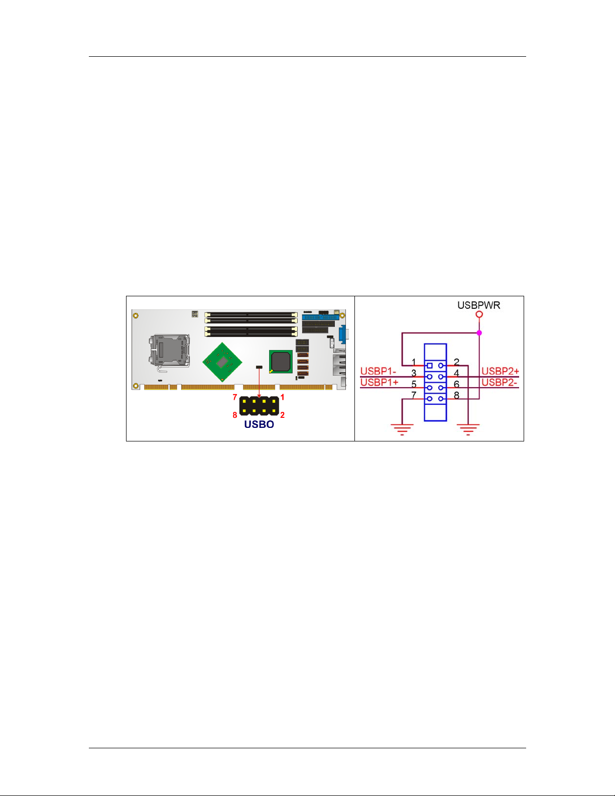
CEGA Series CyberResearch® CPU Cards
4.2.13 USB Connectors (Internal)
CN Label:
CN Type:
CN Location:
CN Pinouts:
The 2x4 USB pin connectors provide connectivity to two USB 1.1 or two USB 2.0 ports.
One additional external USB port is found on the backplate. The CEGA Series supports up
to four more (7 total) via PCI Express x 16 signaling and a compatible backplane. See our
website or call our sales engineers for more detail.
USB0
8-pin header (2x4)
See Figure 4-13
See Table 4-14
Figure 4-14: USB Connector Pinout Locations
52 ©Copyright 2007 CyberResearch, Inc
Page 73
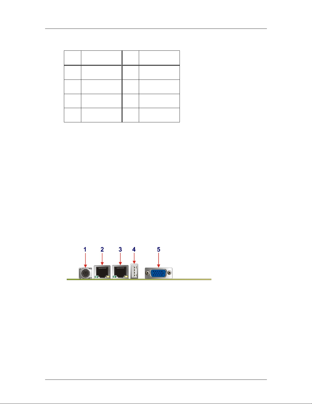
CyberResearch® CPU Cards CEGA Series
PIN DESCRIPTION PIN DESCRIPTION
1 PWR (+5V) 2 GND
3 USBPB- 4 USBPB+
5 USBPA+ 6 USBPB-
7 GND 8 PWR (+5V)
Table 4-15: USB Port Connector Pinouts
4.3 External Peripheral Interface Connectors
Figure 4-15 shows the CEGA external peripheral connector panel. The peripheral
connectors on the panel can be connected to devices externally when the backplane is
installed in a chassis. The external peripheral connectors are:
1 x Keyboard/Mouse connector (labeled 1)
2 x RJ-45 GbE connectors (labeled 2 and 3)
1 x USB 2.0 port (labeled 4)
1 x VGA connector (labeled 5)
Figure 4-15: CEGA External Peripheral Connector Panel
4.3.1 Keyboard/Mouse Connector
CN Label: KB/MS
CN Type: PS/2
CN Location:
CN Pinouts:
See Figure 4-15 (labeled 1)
See Figure 4-16, Table 4-16 and Table 4-17
CyberResearch, Inc. 53
25 Business Park Drive P: (203) 483-8815; F: (203) 483-9024
Branford, CT USA www.cyberresearch.com
Page 74

CEGA Series CyberResearch® CPU Cards
The CEGA keyboard and mouse connector is a standard PS/2 connector.
Figure 4-16: PS/2 Pinout and Configuration
PIN DESCRIPTION
1 KB DATA
2 NC
3 GND
4 VCC
5 KB CLOCK
6 NC
Table 4-16: Keyboard Connector Pinouts
PIN DESCRIPTION
1 MS DATA
2 NC
3 GND
4 VCC
5 MS CLOCK
6 NC
Table 4-17: Mouse Connector Pinouts
54 ©Copyright 2007 CyberResearch, Inc
Page 75

CyberResearch® CPU Cards CEGA Series
4.3.2 Ethernet Connector
CN Label: LAN1 and LAN2
CN Typ e: RJ-45 ports
CN Location:
CN Pinouts:
See Figure 4-15 (labeled 2 and 3)
See Table 4-18 and Table 4-19
A 1Gb connection can be made between the Ethernet connectors and a Local Area
Network (LAN) through a network hub.
PIN DESCRIPTION PIN DESCRIPTION
1 TX+ (or MDX0+) 5 N/C (or MDX2-)
2 TX- (or MDX0-) 6 RX- (or MDX1-)
3 RX+ (or MDX1+) 7 N/C (or MDX3+)
4 N/C (or MDX2+) 8 N/C (or MDX3-)
13 MDX0+ 17 MDX2-
14 MDX0- 18 MDX1-
15 MDX1+ 19 MDX3+
16 MDX2+ 20 MDX3-
1 TX+ (or MDX0+) 5 N/C (or MDX2-)
2 TX- (or MDX0-) 6 RX- (or MDX1-)
Table 4-18: Ethernet Connector Pinouts
CyberResearch, Inc. 55
25 Business Park Drive P: (203) 483-8815; F: (203) 483-9024
Branford, CT USA www.cyberresearch.com
Page 76

CEGA Series CyberResearch® CPU Cards
Figure 4-17: Ethernet Connector
The RJ-45 Ethernet connector has two status LEDs, one green and one yello w. The green
LED indicates activity on the port and the yellow LED indicates the port is linked
(Table 4-19).
SPEED LED LINK LED
Status Description Status Description
GREEN ON: 100MB
Table 4-19: Ethernet Connector LEDs
4.3.3 USB Connector
CN Label: USB_C0
CN Type: USB port
CN Location:
CN Pinouts:
USB devices connect directly to the USB connector on the external peripheral connector
panel.
YELLOW ON: Linked
OFF: 10MB
See Figure 4-15 (labeled 4)
See Table 4-20
Flashing: Activity
56 ©Copyright 2007 CyberResearch, Inc
Page 77

CyberResearch® CPU Cards CEGA Series
PIN DESCRIPTION PIN DESCRIPTION
1 VCC 5 VCC
2 USBD0- 6 USBD0-
3 USBD0+ 7 USBD0+
4 GND 8 GND
Table 4-20: USB Connector Pinouts
4.3.4 VGA Connector
CN Label: VGA
CN Type: HD-D-sub 15 Female connector
CN Location:
CN Pinouts:
See Figure 4-15 (labeled 5)
See Figure 4-18 and Table 4-21
The standard HD-D-sub 15 female connector connects to a CRT or LCD monitor.
Figure 4-18: VGA Connector
PIN Description PIN Description
1 RED 2 GREEN
3 BLUE 4 N/C
5 GND 6 GND
7 GND 8 GND
CyberResearch, Inc. 57
25 Business Park Drive P: (203) 483-8815; F: (203) 483-9024
Branford, CT USA www.cyberresearch.com
Page 78

CEGA Series CyberResearch® CPU Cards
9 VCC 10 GND
11 N/C 12 DDC DAT
13 HSYNC 14 VSYNC
15 DDC CLK
Table 4-21: VGA Connector Pinouts
4.4 On-board Jumpers
The CEGA has fifteen on-board jumpers. Refer to Section 5.4 for jumper configuration
settings.
58 ©Copyright 2007 CyberResearch, Inc
Page 79

CyberResearch® CPU Cards CEGA Series
0 0
Chapter
5
5 Installation
CyberResearch, Inc. 59
25 Business Park Drive P: (203) 483-8815; F: (203) 483-9024
Branford, CT USA www.cyberresearch.com
Page 80

CEGA Series CyberResearch® CPU Cards
5.1 Anti-static Precautions
WARNING:
Failure to take ESD precautions during the installation of the CEGA
may result in permanent damage to the CEGA and severe injury to the
user.
Electrostatic discharge (ESD) can cause serious damage to electronic components,
including the CEGA. Dry climates are especially susceptible to ESD. It is therefore critical
that whenever the CEGA, or any other electrical component is handled, the following
anti-static precautions are strictly adhered to.
Wear an anti-static wristband: Wearing a simple an t i-static wristband can
help to prevent ESD from damaging the board.
Self-grounding: Before handling the board, touch any grounded conducting
material. During the time the board is handled, frequently touch any
conducting materials that are connected to the ground.
Use an anti-static pad: When configuring the CEGA, place it on an
antic-static pad. This reduces the possibility of ESD damage.
Only handle the edges of the PCB: When handling the PCB, hold it by its
edges.
60 ©Copyright 2007 CyberResearch, Inc
Page 81

CyberResearch® CPU Cards CEGA Series
5.2 Installation Considerations
NOTE:
The following installation notices and installation considerations should
be read and understood before the CEGA is installed. All installation
notices pertaining to the installation of the CEGA should be strictly
adhered to. Failing to adhere to these precautions may lead to severe
damage of the CEGA and injury to the person installing the backplane.
5.2.1 Installation Notices
WARNING:
The installation instructions described in this manual should be
carefully followed in order to prevent damage to the CEGA and injury to
the user.
Before and during the installation please DO the following:
Read the user manual:
o The user manual provides a complete description of the CEGA
installation instructions and configuration options.
Wear an electrostatic discharge cuff (ESD):
o Electronic components are easily damaged by ESD. Wearing an ESD cuff
removes ESD from the body and helps prevent ESD damage.
Place the CEGA on an antistatic pad:
o When installing or configuring the backplane, place it on an antistatic pad.
This helps to prevent potential ESD damage.
Turn off all power to the CEGA:
o When working with the CEGA, make sure that it is disconnected from all
power supplies and that no electricity is being fed into the system.
Before and during the installation of the CEGA DO NOT:
Remove any of the stickers on the PCB board. These stickers are required for
warranty validation.
Use the product before verifying all the cables and power connectors are
CyberResearch, Inc. 61
25 Business Park Drive P: (203) 483-8815; F: (203) 483-9024
Branford, CT USA www.cyberresearch.com
Page 82

CEGA Series CyberResearch® CPU Cards
properly connected.
Allow screws to come in contact with the PCB circuit, connector pins, or its
components.
5.2.2 Installation Checklist
The following checklist is provided to ensure the CEGA is properly installed.
All the items in the packing list are present (see Chapter 3)
A CPU is installed
A CPU cooling kit is properly installed
Compatible memory modules are properly inserted into the memory slots
The CEGA is installed into a chassis with adequate ventilation
The correct power supply is being used
The following devices (if applicable) are properly connected
o IDE device
o SATA drives
o Floppy disk drive
o System front panel connector
o Audio kit
o Power supply
o USB cable
o Serial port cable
o Parallel port cable
o Keyboard/mouse cable
o COM port cables
The following external peripheral devices are properly connected to the
chassis:
o VGA screen
o Keyboard
o Mouse
o USB device
o LAN
62 ©Copyright 2007 CyberResearch, Inc
Page 83
CyberResearch® CPU Cards CEGA Series
5.3 CPU, CPU Cooling Kit and DIMM Installation
WARNING:
A CPU should never be turned on without the specified cooling kit
being installed. If the cooling kit (heat sink and fan) is not properly
installed and the system turned on, permanent damage to the CPU,
CEGA and other electronic components attached to the system may be
incurred. Running a CPU without a cooling kit may also result in injury
to the user.
The CPU, CPU cooling kit and DIMM are the most critical components of the CEGA. If one
of these component is not installed the CEGA cannot run.
5.3.1 Socket LGA775 CPU Installation
NOTE:
Enabling Hyper-Threading Technology on the system requires meeting
all of the platform requirements listed below:
CPU: An Intel® Pentium 4 Processor (or better) with HT
Technology must be installed
Chipset: An Intel® Chipset that supports HT Technology
OS: An operating system that has optimizations for HT
Technology
WARNING:
CPUs are expensive and sensitive components. When installing the
CPU please be careful not to damage it in anyway. Make sure the CPU
is installed properly and ensure the correct cooling kit is properly
installed.
The LGA775 is shown in Figure 5-1.
CyberResearch, Inc. 63
25 Business Park Drive P: (203) 483-8815; F: (203) 483-9024
Branford, CT USA www.cyberresearch.com
Page 84
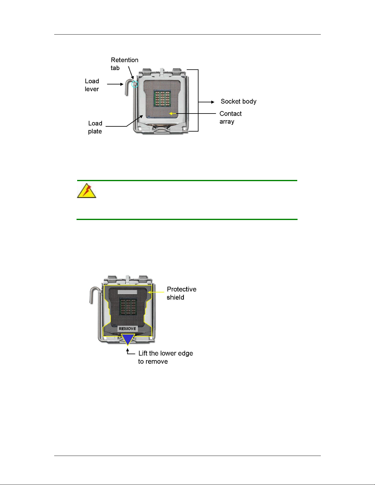
CEGA Series CyberResearch® CPU Cards
Figure 5-1: Intel LGA775
To install a LGA775 CPU onto the CEGA, follow the steps below:
WARNING:
When handling the CPU, only hold it on the sides. DO NOT touch the
pins at the bottom of the CPU.
Step 1: Remove the protective cover. Remove the black protective cover by prying it
off the load plate. To remove the protective cover, locate the “REMOVE” sign
and use your fingernail to pry the protective cover off. See Figure 5-2.
Figure 5-2: Remove the CPU Socket Protective Shield
Step 2: Open the socket. Disengage the load lever by pressing the lever down and
slightly outward to clear the retention tab. Rotate the load lever to a fully open
position. Then rotate the load plate towards the opposite directio n. See Figure
5-3.
64 ©Copyright 2007 CyberResearch, Inc
Page 85
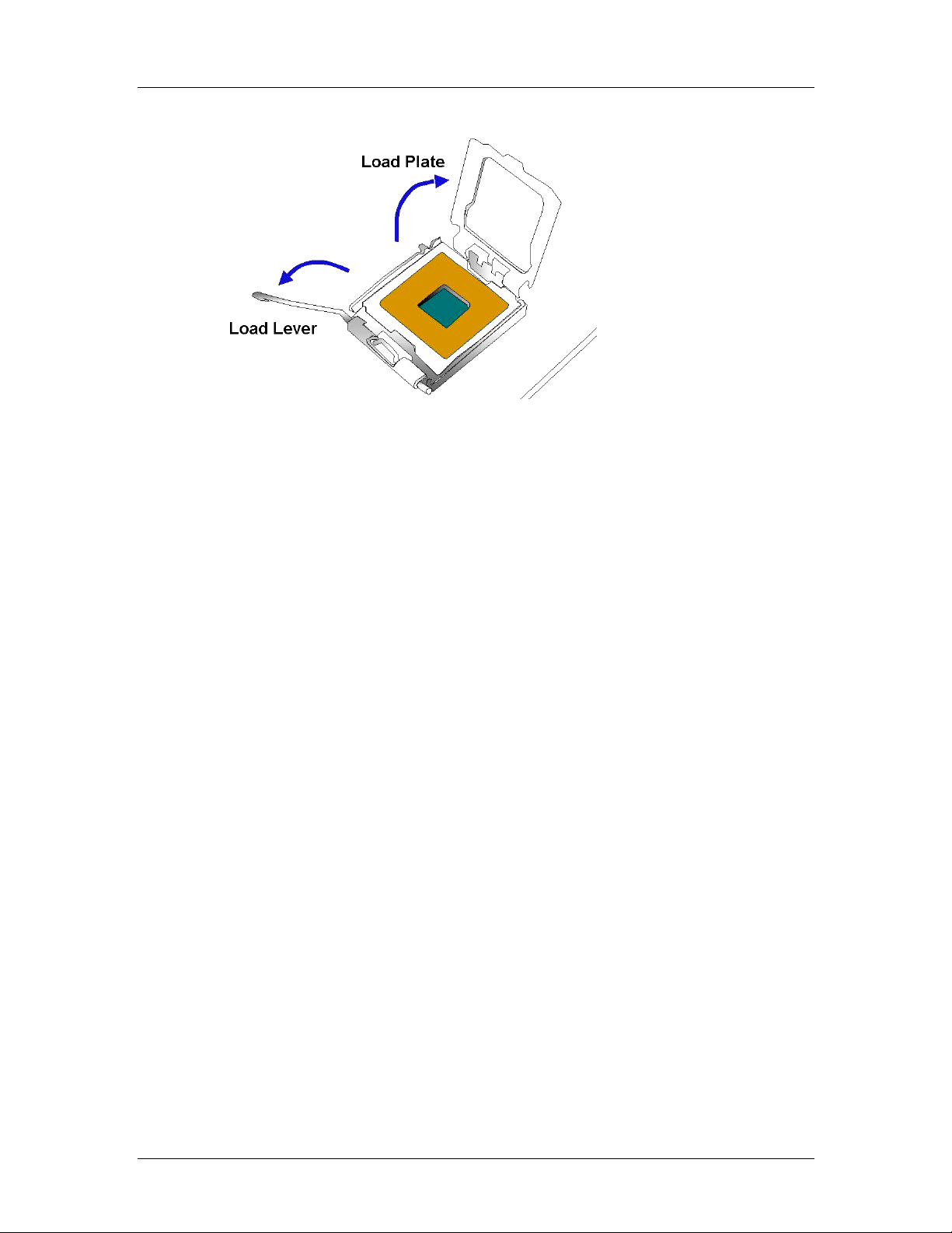
CyberResearch® CPU Cards CEGA Series
Figure 5-3: Open the CPU Socket Load Plate
Step 3: Inspect the CPU socket Make sure there are no be nt pins and make sure the
socket contacts are free of foreign material. If any debris is found, remove it with
compressed air.
Step 4:
Step 5: Orientate the CPU properly. Make sure the IHS (Integrated Heat Sink) side is
facing upward.
Step 6: Correctly position the CPU. Match the Pin 1 mark with the cut edge on the
CPU socket.
Step 7: Align the CPU pins. Locate pin 1 and the two orientation notches on the CPU.
Carefully match the two orientation notches on the CPU with the socket
alignment keys.
Step 8: Insert the CPU. Gently insert the CPU into the socket. If the CPU pins are
properly aligned, the CPU should slide into the CPU socket smoothly. See
Figure 5-4.
CyberResearch, Inc. 65
25 Business Park Drive P: (203) 483-8815; F: (203) 483-9024
Branford, CT USA www.cyberresearch.com
Page 86
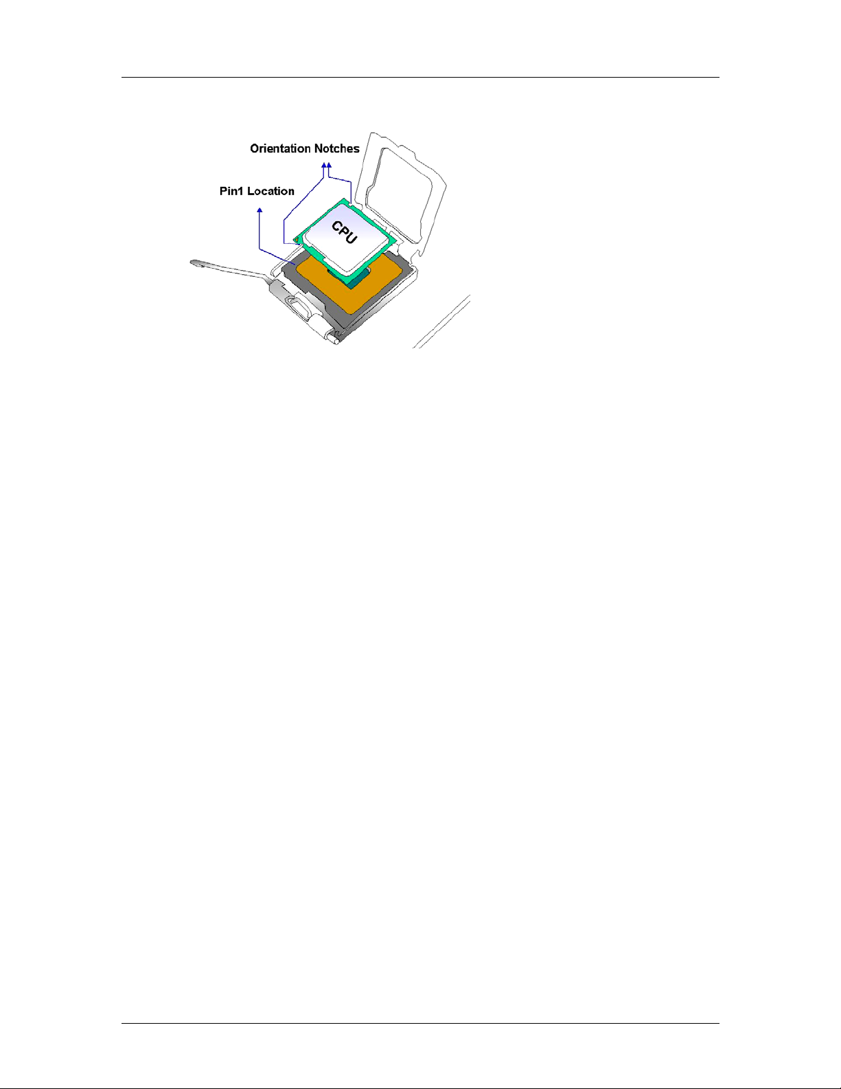
CEGA Series CyberResearch® CPU Cards
Figure 5-4: Insert the LGA775 CPU
Step 9: Close the CPU socket. Close the load plate and engage the load lever by
pushing it back to its original position. Secure the load lever under the retention
tab on the side of CPU socket.
Step 10: Connect the CPU 12V cable to the 12Af t er the cooling kit is installed
connect the CPU cable to the CPU 12V power connectorStep 0:
66 ©Copyright 2007 CyberResearch, Inc
Page 87
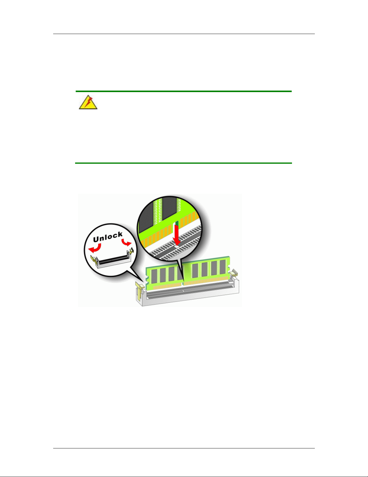
CyberResearch® CPU Cards CEGA Series
5.3.2 DIMM Installation
WARNING:
Using incorrectly specified DIMM may cause permanent damage the
CEGA. Please make sure the purchased DIMM complies with the
memory specifications of the CEGA. DIMM specifications compliant
with the CEGA are listed in Chapter 2.
To install a DIMM into a DIMM socket, please follow the steps below and refer to
Figure 5-5.
Figure 5-5: Installing a DIMM
Step 1: Open the DIMM socket handles. The DIMM socket has two handles that
secure the DIMM into the socket. Before the DIMM can be inserted into the
socket, the handles must be opened. See Figure 5-5.
Step 2: Align the DIMM with the socket. The DIMM must be oriented so that the notch
in the middle of the DIMM aligns with the bridge in the socket. See Figure 5-5.
Step 3: Insert the DIMM. Once properly aligned, the DIMM can be inserted into the
CyberResearch, Inc. 67
25 Business Park Drive P: (203) 483-8815; F: (203) 483-9024
Branford, CT USA www.cyberresearch.com
Page 88
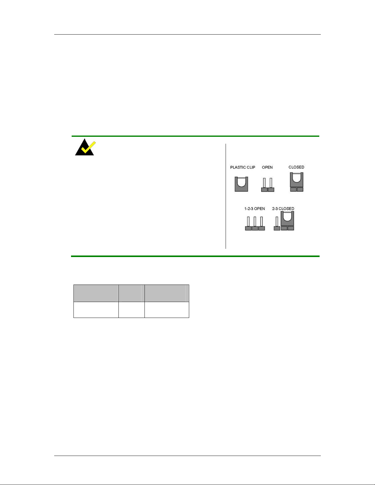
CEGA Series CyberResearch® CPU Cards
socket. As the DIMM is inserted, the white handles on the side of the socket will
close automatically and secure the DIMM to the socket. See Figure 5-5.
Step 4: Removing a DIMM. To remove a DIMM, push both handles outward. The
memory module is ejected by a mechanism in the socket.Step 0:
5.4 Jumper Settings
NOTE:
A jumper is a metal bridge used to close an
electrical circuit. It consists of two or three metal
pins and a small metal clip (often protected by a
plastic cover) that slides over the pins to connect
them. To CLOSE/SHORT a jumper means
connecting the pins of the jumper with the plastic
clip and to OPEN a jumper means removing the
plastic clip from a jumper.
Before the CEGA is installed in the system, the jumpers must be set in accordance with
the desired configuration. The jumpers on the CEGA are listed in Table 5-1.
Description Label Type
Clear CMOS JP1 3-pin header
Table 5-1: Jumpers
Figure 5-6: Jumper
68 ©Copyright 2007 CyberResearch, Inc
Page 89

CyberResearch® CPU Cards CEGA Series
5.4.1 Clear CMOS Jumper
Jumper Label:
Jumper Type:
Jumper Settings:
Jumper Location:
JP1
3-pin header
See Table 5-2
See Figure 5-7
If the CEGA fails to boot due to improper BIOS settings, the clear CMOS jumper clears the
CMOS data and resets the system BIOS information. To do this, use the jumper cap to
close pins 2 and 3 for a few seconds then reinstall the jumper clip back to pins 1 and 2.
If the “CMOS Settings Wrong” message is displayed during boot up, the fault may be
corrected by pressing the F1 to enter the CMOS Setup menu. Do one of the following:
Enter the correct CMOS setting
Load Optimal Defaults
Load Failsafe Defaults.
After having done one of the above, save the changes and exit the CMOS Setup menu.
The clear CMOS jumper settings are shown in Table 5-2.
AT Power Select Description
Short 1 - 2 Keep CMOS Setup Default
Short 2 – 3 Clear CMOS Setup
Table 5-2: Clear CMOS Jumper Settings
The location of the clear CMOS jumper is shown in Figure 5-7 below.
CyberResearch, Inc. 69
25 Business Park Drive P: (203) 483-8815; F: (203) 483-9024
Branford, CT USA www.cyberresearch.com
Page 90

CEGA Series CyberResearch® CPU Cards
Figure 5-7: Clear CMOS Jumper
5.5 Chassis Installation
5.5.1 Airflow
WARNING
Airflow is critical to the cooling of the CPU and other onboard
components. The chassis in which the CEGA must have air vents to
allow cool air to move into the system and hot air to move out.
The CEGA must be installed in a chassis with ventilation holes on the sides allowing
airflow to travel through the heat sink surface. In a system with an individual power supply
unit, the cooling fan of a power supply can also help generate airflow through the board
surface.
NOTE
CYBERRESEARCH, INC. has a wide range of chassis available.
Please contact a CYBERRESEARCH, INC. applications engineer by
calling 203-483-8815, Faxing 203-483-9024 attn: sales, or e-mailing
sales@cyberresearch.com
to find out more about available chassis.
70 ©Copyright 2007 CyberResearch, Inc
Page 91

CyberResearch® CPU Cards CEGA Series
5.5.2 Backplane Installation
Before the CEGA can be installed into a chassis, a backplane must first be installed.
Please refer to the installation instructions that came with the backplane and the chassis.
NOTE:
CYBERRESEARCH, INC. has a wide range of backplanes available.
Please contact a CYBERRESEARCH, INC. applications engineer by
calling 203-483-8815, Faxing 203-483-9024 attn: sales, or e-mailing
sales@cyberresearch.com
to find out more about available
backplanes.
5.5.3 CPU Card Installation
To install the CEGA CPU card onto the backplane, carefully align the CPU card interface
connectors with the corresponding socket on the backplane. To do this, please refer to the
reference material that came with the backplane. Next, secure the CPU card to the
chassis. To do this, please refer to the reference material that came with the chassis.
5.6 Internal Peripheral Device Connections
5.6.1 Peripheral Device Cables
The cables listed in Table 5-3 are shipped with the CEGA.
Quantity Type
1 ATA 66/100 flat cable
1 KB/MS PS/2 Y cable
1 RS-232 cable
4 SATA drive cable
2 SATA drive power cable
CyberResearch, Inc. 71
25 Business Park Drive P: (203) 483-8815; F: (203) 483-9024
Branford, CT USA www.cyberresearch.com
Page 92

CEGA Series CyberResearch® CPU Cards
1 USB cable
Table 5-3: Cables Provided with CEGA
5.6.2 ATA Flat Cable Connection
The ATA 66/100 flat cable connects to the CEGA IDE device. Follow the instructions
below to connect an IDE HDD to the CEGA.
Step 1: Locate the IDE connector. The locations of the IDE device connectors are
shown in Chapter 3.
Step 2: Insert the connector. Connect the IDE cable connector to the onboard
connector. See Figure 5-8. A key on the front of the cable connector ensures it
can only be inserted in one direction.
Figure 5-8: IDE Cable Connection
Step 3: Connect the cable to an IDE device. Connect the two connectors on the other
side of the cable to one or two IDE devices. Make sure that pin 1 on the cable
corresponds to pin 1 on the connectorStep 0:
72 ©Copyright 2007 CyberResearch, Inc
Page 93

CyberResearch® CPU Cards CEGA Series
5.6.3 Keyboard/Mouse Y-cable Connector
The CEGA is shipped with a keyboard/mouse Y-cable connector. The keyboard/mouse
Y-cable connector connects to a keyboard/mouse connector on the CEGA and branches
into two cables that are each connected to a PS/2 connector, one for a mouse and one for
a keyboard. To connect the keyboard/mouse Y-cable connector please follow the steps
below.
Step 1: Locate the connector. The location of the keyboard/mouse Y-cable connector
is shown in Chapter 3.
Step 2: Align the connectors. Correctly align pin 1 on the cable connector with pin 1 on
the CEGA keyboard/m ouse connector. See Figure 5-9.
Step 3: Insert the cable connectors. Once the cable connector i s p rope rly aligned wit h
the keyboard/mouse connector on the CEGA, connect the cable connector to
the onboard connectors. See Figure 5-9.
CyberResearch, Inc. 73
25 Business Park Drive P: (203) 483-8815; F: (203) 483-9024
Branford, CT USA www.cyberresearch.com
Page 94

CEGA Series CyberResearch® CPU Cards
Figure 5-9: Keyboard/mouse Y-cable Connection
Step 4: Attach PS/2 connectors to the chassis. The keyboard/mouse Y-cable
connector is connected to two PS/2 connectors. To secure the PS/2 connectors
to the chassis please refer to the installation instructions that came with the
chassis.
Step 5: Connect the keyboard and mouse. Once the PS/2 connectors are connected
to the chassis, a keyboard and mouse can each be connected to one of the
PS/2 connectors. The keyboard PS/2 connector and mouse PS/2 connector are
both marked. Please make sure the keyboard and mouse are connected to the
correct PS/2 connector. Step 0:
5.6.4 Single RS-232 Cable Connection
The single RS-232 cable consists of one serial port connector attached to a serial
communications cable that is then attached to a D-sub 9 male connector that is mounted
onto a bracket. To install the single RS-232 cable, please follow the steps below.
Step 1: Locate the connector. The location of the RS-232 co nnector is shown in
Chapter 3.
Step 2: Insert the cable connector. Insert the connector into the serial port box header .
See Figure 5-10. A key on the front of the cable connector ensures the
connector can only be installed in one direction.
74 ©Copyright 2007 CyberResearch, Inc
Page 95

CyberResearch® CPU Cards CEGA Series
Figure 5-10: Single RS-232 Cable Installation
Step 3: Secure the bracket. The single RS-232 connector has one D-sub 9 male
connector secured to a bracket. To secure the bracket to the chassis please
refer to the reference material that came with the chassisStep 0:
5.6.5 SATA Drive Connection
The CEGA is shipped with SATA drive cables and power cable. Follow these steps to
connect the SATA drives.
Step 1: Locate the connectors. The SATA drive connectors are shown in Chapter 3.
Step 2: Insert the cable connector. Press the clip on the connector at the end of the
SATA cable and insert the cable connector into the onboard SATA drive
connector. See Figure 5-11.
CyberResearch, Inc. 75
25 Business Park Drive P: (203) 483-8815; F: (203) 483-9024
Branford, CT USA www.cyberresearch.com
Page 96
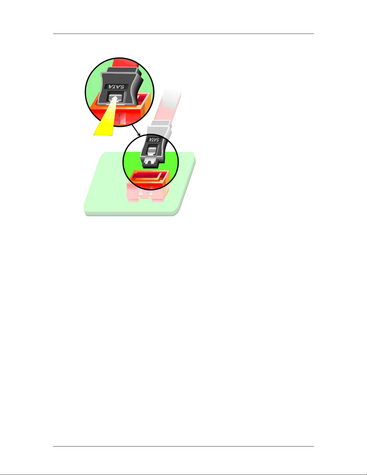
CEGA Series CyberResearch® CPU Cards
Figure 5-11: SATA Drive Cable Connection
Step 3: Connect the cable to the SA TA disk. Connect the connector on the other end
of the cable to the connector at the back of the SATA drive. See Figure 5-12.
Step 4: Connect the SATA po wer cable. Connect the SATA power connector to the
back of the SATA drive. Se e Figure 5-12. Step 0:
76 ©Copyright 2007 CyberResearch, Inc
Page 97
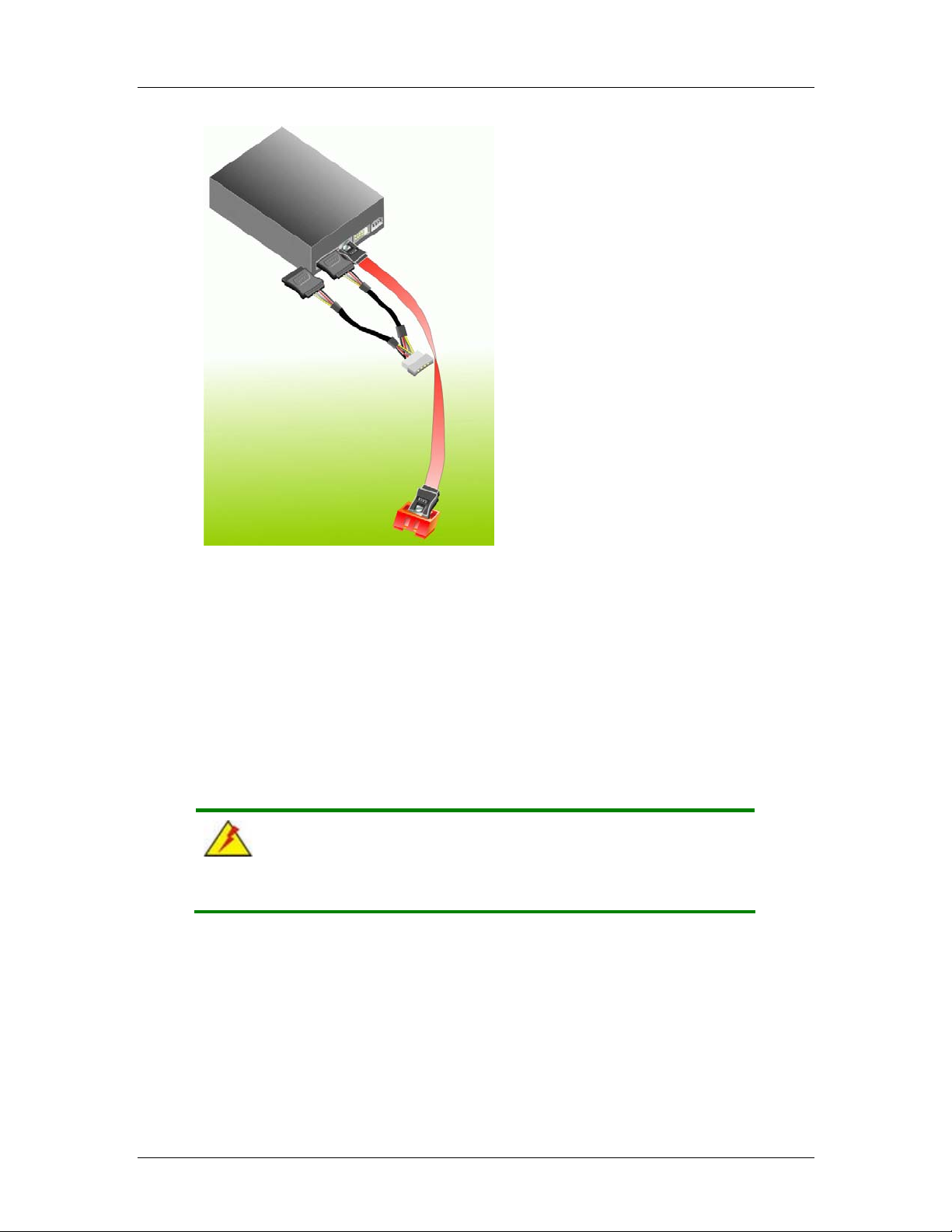
CyberResearch® CPU Cards CEGA Series
Figure 5-12: SATA Power Drive Connection
5.6.6 USB Cable Connectors
The CEGA is shipped with a dual USB 2.0 cable. To connect the USB cable connector,
please follow the steps below.
Step 1: Locate the connectors. The locations of the USB connectors are shown in
Chapter 3.
WARNING:
If the USB pins are not properly aligned, the USB device can burn out.
Step 2: Align the connectors. The cable has two connectors. Correctly align pin 1 on
each cable connector with pin 1 on the CEGA USB connector.
Step 3: Insert the cable connectors. Once the cable connectors are properly aligned
with the USB connectors on the CEGA, connect the cable connectors to the
CyberResearch, Inc. 77
25 Business Park Drive P: (203) 483-8815; F: (203) 483-9024
Branford, CT USA www.cyberresearch.com
Page 98
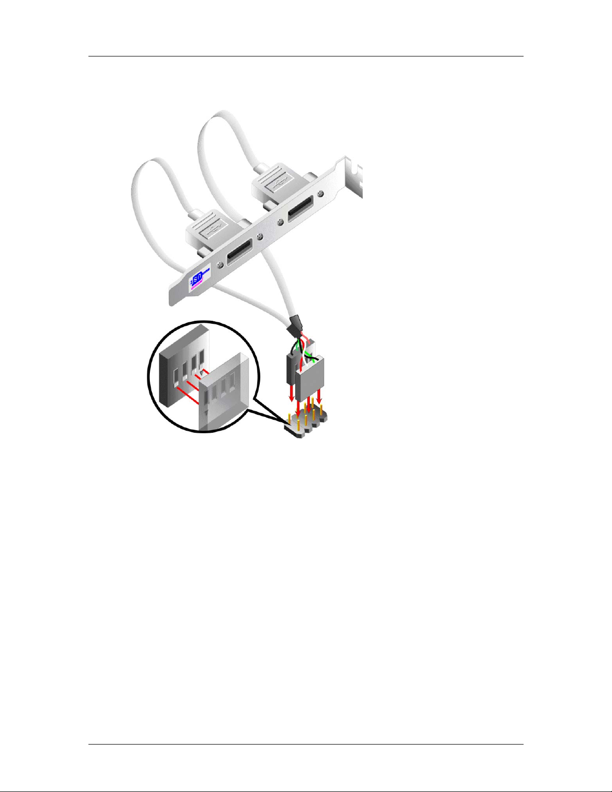
CEGA Series CyberResearch® CPU Cards
onboard connectors. See Figure 5-13.
Figure 5-13: Dual USB Cable Connection
Step 4: Attach the bracket to the chassis. The USB 2.0 connectors are attached to a
bracket. To secure the bracket to the chassis please refer to the installation
instructions that came with the chassis.Step 0:
5.7 External Peripheral Interface Connection
The following external peripheral devices can be connected to the external peripheral
interface connectors.
Mouse and keyboard
RJ-45 Ethernet cable connectors
USB devices
VGA monitors
78 ©Copyright 2007 CyberResearch, Inc
Page 99
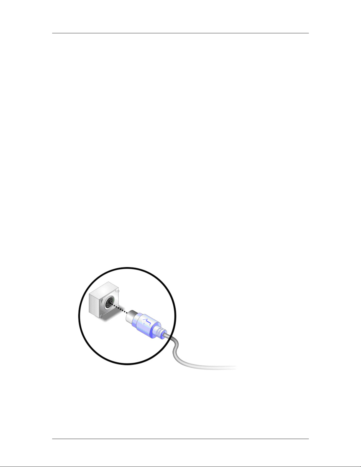
CyberResearch® CPU Cards CEGA Series
To install these devices, connect the corresponding cable connector from the actual
device to the corresponding CEGA external peripheral interface connector making sure
the pins are properly aligned.
5.7.1 PS/2 Y Cable Connection
The CEGA has a single PS/2 connector on the external peripheral interface panel. The
PS/2 connector is connected to a keyboard and mouse Y cable. To connect a ke yboard to
the CEGA, please follow the instructions below.
Step 1: Locate the PS/2 connector. The location of the PS/2 connector is shown in
Chapter 3.
Step 2: Align the PS/2 connector. Align the PS/2 connector o n the keyboard cable with
the PS/2 connector on the external peripheral interface.
Step 3: Insert the PS/2 connector. Once the connectors are properly aligned, insert
the PS/2 Y cable connector into the PS/2 cable connector on the CEGA.
See Figure 5-14.Step 0:
CyberResearch, Inc. 79
25 Business Park Drive P: (203) 483-8815; F: (203) 483-9024
Branford, CT USA www.cyberresearch.com
Page 100

CEGA Series CyberResearch® CPU Cards
Figure 5-14: PS/2 Connector
5.7.2 RJ-45 Ethernet Connection
The CEGA RJ-45 Ethernet connector on the external peripheral interface panel is
connected to a LAN cable RJ-45 connector (Figure 5-15).
Figure 5-15: RJ-45 Connector
80 ©Copyright 2007 CyberResearch, Inc
 Loading...