

Page 1
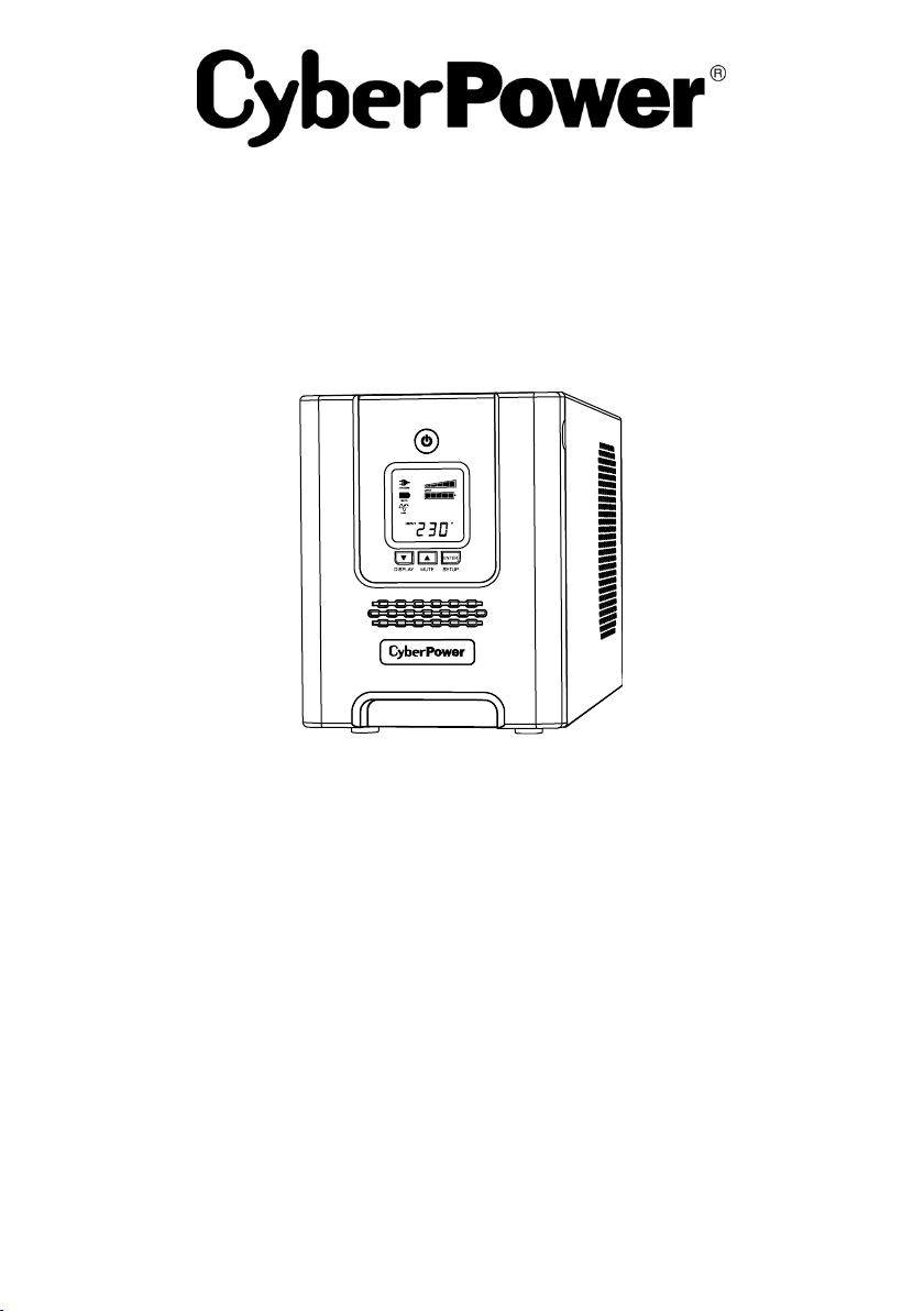
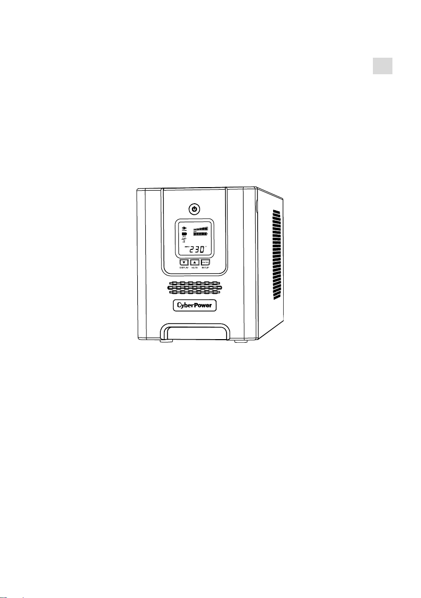
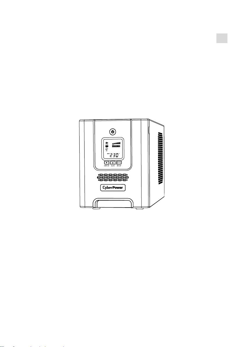
PR2200ELCDSL / PR3000ELCDSL
PR2200ELCDSXL / PR3000ELCDSXL
User’s Manual
K01-0000391-01
Page 2

IMPORTANT SAFETY INSTRUCTIONS
This manual contains important safety instructions. Please read and follow all instructions carefully
during installation and operation of the unit. Read this manual thoroughly before attempting to unpack,
install, or operate your UPS.
CAUTION! The UPS must be connected to a grounded AC power outlet with fuse or circuit breaker
protection. DO NOT plug the UPS into an outlet that is not grounded. If you need to de-energize this
equipment, turn off and unplug the UPS.
CAUTION! DO NOT USE FOR MEDICAL OR LIFE SUPPORT EQUIPMENT! CyberPower Systems
does not sell products for life support or medical applications. DO NOT use in any circumstance that
would affect the operation and safety of life support equipment, medical applications, or patient care.
CAUTION! Hazardous live parts inside can be energized by the battery even when the AC input power
is disconnected.
CAUTION! To prevent the risk of fire or electric shock, install in a temperature and humidity controlled
indoor area, free of conductive contaminants. (Please see specifications for acceptable temperature
and humidity range).
CAUTION! To reduce the risk of electric shock, do not remove the cover, except to service the battery.
There are no user serviceable parts inside, except for the battery.
CAUTION! To avoid electrical shock, turn off the unit and unplug it from the AC power source before
servicing the battery or installing a computer component.
CAUTION! DO NOT USE WITH OR NEAR AQUARIUMS! To reduce the risk of fire, do not use with or
near aquariums. Condensation from the aquarium can come in contact with metal electrical contacts
and cause the machine to short out.
INSTALLING YOUR UPS SYSTEM
UNPACKING
The box should contain the following:
(1) UPS Unit x 1; (2) Emergency Power Off Cable (gray) x 1; (3) Serial Cable x 1; (4) USB Cable x 1 (5)
User Manual x 1; (6) Function Setup Guide x 1; (7) Power cord x 4
*PowerPanel® Business Edition software is available on our website. Please visit
www.cyberpower.com and go to the Software Section for free download.
OVERVIEW
The PR2200/3000ELCDSL, PR2200/3000ELCDSXL provides automatic voltage regulation for
inconsistent utility power. The PR2200/3000ELCDSL, PR2200/3000ELCDSXL features 405 Joules of
surge protection, and provides battery backup during power outages. The PR2200/3000ELCDSL,
PR2200/3000ELCDSXL ensures consistent power to your computer system and its included software
will automatically save your open files and shut down your computer system during a utility power loss.
HOW TO DETERMINE THE POWER REQUIREMENTS OF YOUR
EQUIPMENT
1. Make sure that the total Volt-Amp (VA) requirements of your computer, monitor, and peripheral
equipment does not exceed 2200VA/3000VA.
2. Ensure that the equipment plugged into the battery power-supplied/surge outlets does not exceed
the UPS unit's rated capacity (2200VA/1980 W for PR2200ELCDSL/PR2200ELCDSXL,
3000VA/2700W for PR3000ELCDSL/PR3000ELCDSXL). If the rated unit capacities are exceeded,
an overload condition may occur and cause the UPS unit to shut down or the circuit breaker to trip.
2
Page 3
Communication Ports
See Installati on Instruction s
Supply
TVSS GND
Before Con necting ToThe
Provides SNM P Card Communication
Expansion Port
Input
+
MUTEDISPL AY SETUP
ENTER
+
48VDC 70A MAX
1
2
4
5
6
7
7
8
9
10
11
12
13
3
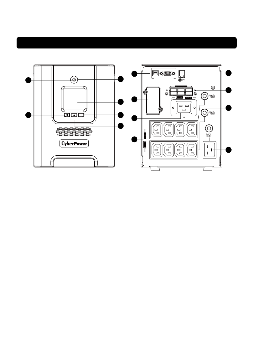
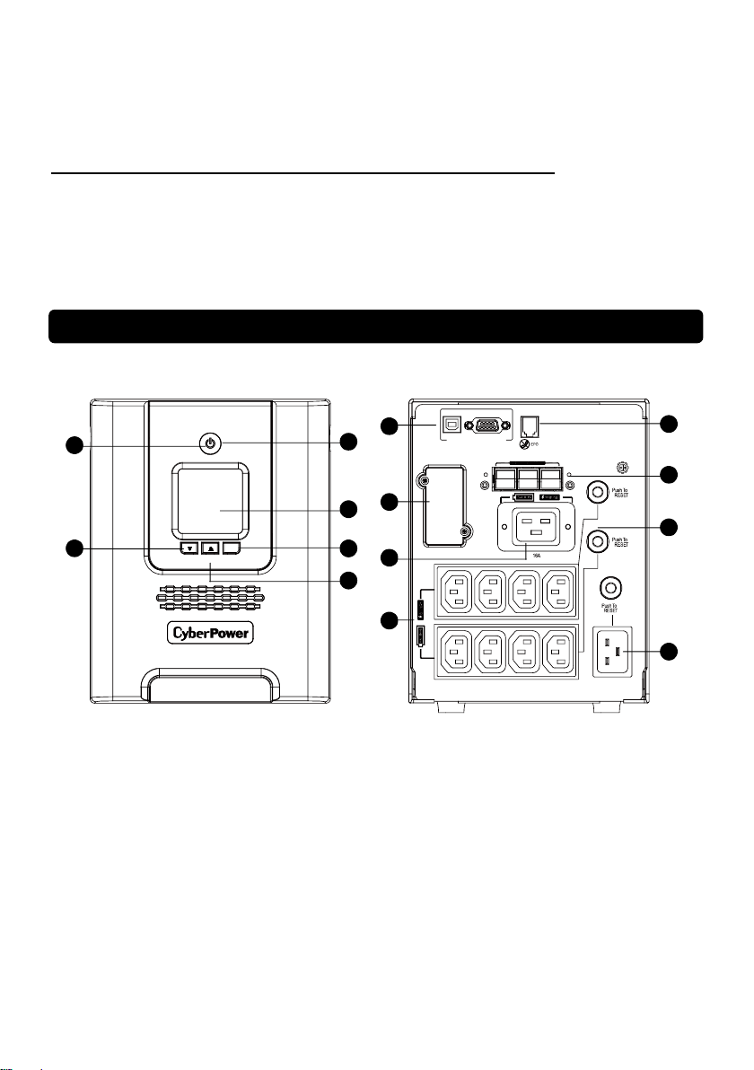
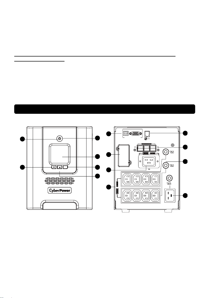
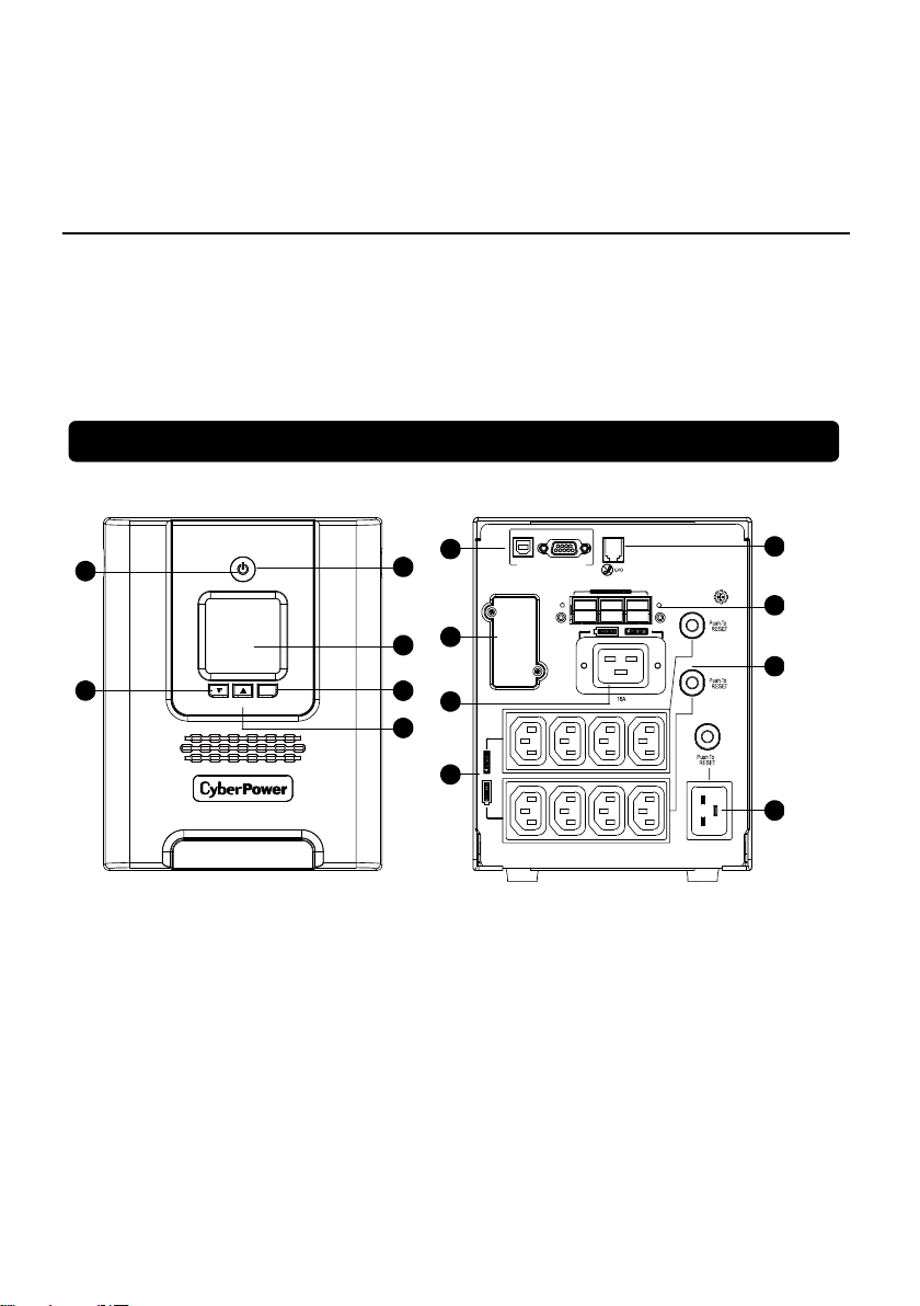
DESCRIPTION
1. Power Switch
Used as the master on/off switch for equipment connected to the battery power supplied outlets.
2. Power On Indicator
This LED is illuminated when the utility power is normal and the UPS outlets are providing power,
free of surges and spikes.
3. LCD Module Display
Intelligent LCD display shows all the UPS information using icons and messages. For more
information please review the “Definitions for Illuminated LCD Indicators” section below.
4. Down/Display Button
The button can be used to select the LCD display contents including Input Voltage, Output Voltage,
and Estimated Run Time. Short press the button to scroll down the function menu. Pressing the
button for 2 seconds will keep the LCD display always on or turn the LCD display off while in
AC/Utility power mode. For more information about the Down/Display Button, please refer to the
Function Setup Guide.
5. Up/Mute Button
Short press the button to scroll up the function menu. Holding the button for more than 2 seconds
will silence the alarm. For more information about the Up/Mute Button, please refer to the Function
Setup Guide.
6. Enter/Setup Button
Press the button for 2 seconds to enter the setup menu and then select the functions for
configuration. For more information about the Enter/Setup Button, please refer to the Function
Setup Guide.
7. Battery and Surge Protected Outlets
The unit has nine battery powered/surge suppression outlets for connected equipment to ensure
BASIC OPERATION
3
Page 4
temporary uninterrupted operation of your equipment during a power failure. (DO NOT plug a laser
printer, paper shredder, copier, space heater, vacuum, sump pump or other large electrical devices
into the “Battery and Surge Protected Outlets”. The power demands of these devices may overload
and damage the unit.)
8. Serial / USB Ports to PC
The Serial and USB ports allow connection and communication between the computer and the
UPS unit. Note: Only one port can be used at a time.
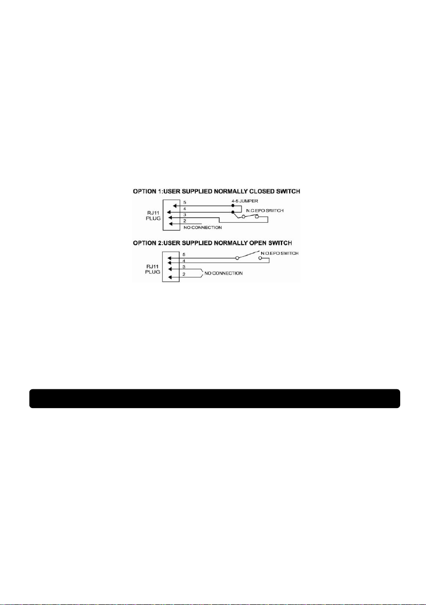
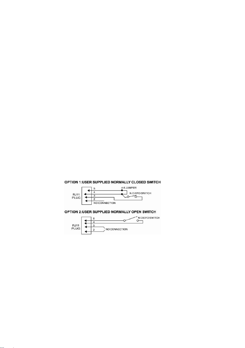
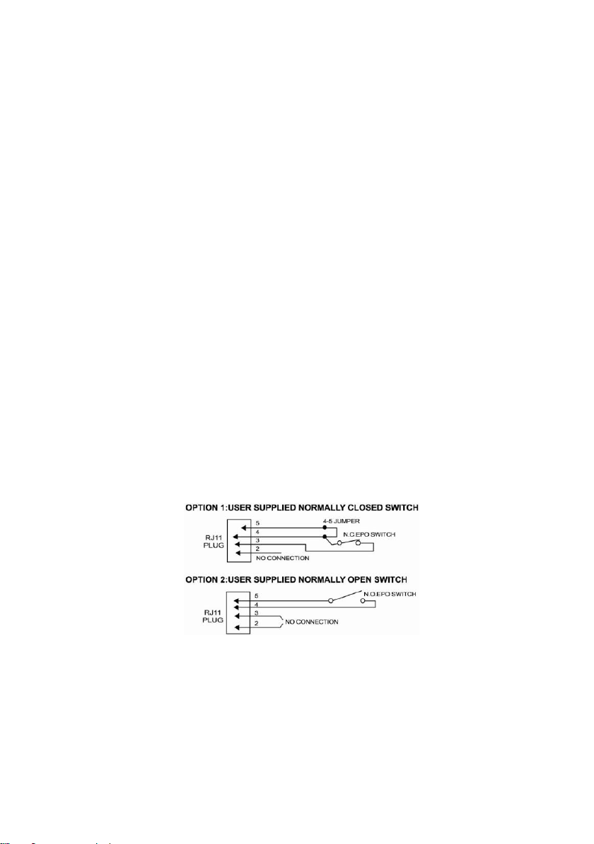
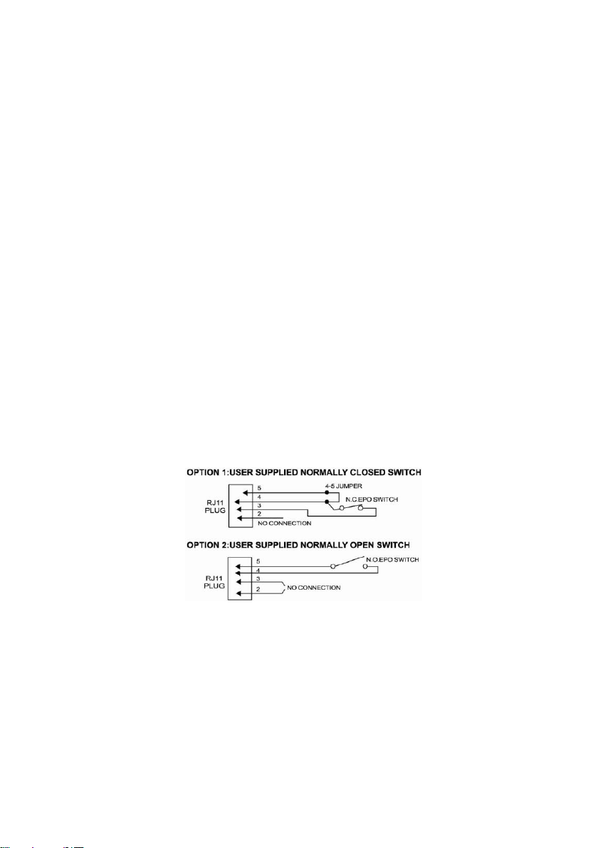
9. EPO Port
Use the provided gray EPO cable to connect to a provided EPO contact switch. Follow the
appropriate circuit diagram to the right to wire the cable to your EPO configuration. The EPO
remote switch is a switch installed in an outside area, connected to the unit via the Emergency
Power Off cable. In case of an emergency, it can be used to immediately cut-off power from the
UPS.
10. SNMP/HTTP Network Slot
Remove the cover panel to install an optional RMCARD to remotely monitor and manage your UPS
over a network.
11. Extended Battery Module Connecter (Except for PR2200ELCDSL/PR3000ELCDSL)
Use to connect optional CyberPower external battery pack (BP48VPT01) for extended runtime.
12. Circuit Breaker
Located on the back of the UPS, the circuit breaker provides overload and fault protection.
13. AC Input
Connect the AC power cord to a properly wired and grounded outlet.
HARDWARE INSTALLATION GUIDE
1. Your new UPS may be used immediately upon receipt. However, recharging the battery for at
least 8 hours is recommended to ensure that the battery's maximum charge capacity is achieved.
Charge loss may occur during shipping and storage. To recharge the battery, simply leave the unit
plugged into an AC outlet. The unit will charge in both the on and off position.
Note: This UPS is designed with a safety feature to keep the system from being turned on
during shipment. The first time you turn the UPS on, you will need to have it connected to
AC power or it will not power up.
2. If you will use the software, connect the USB cable to the USB port on the UPS.
3. With the UPS unit off and unplugged, connect the computer, monitor, and any externally powered
data storage device (Zip drive, Jazz drive, Tape drive, etc. into the battery power supplied outlets.
DO NOT plug a laser printer, copier, space heater, vacuum, paper shredder or other large
electrical device into the battery power supplied outlets. The power demands of these devices will
4
Page 5

overload and possibly damage the unit.
4. Plug the UPS into a 2 pole, 3 wire grounded receptacle (wall outlet). Make sure the wall branch
outlet is protected by a fuse or circuit breaker and does not service equipment with large electrical
demands (e.g. air conditioner, refrigerator, copier, etc. Avoid using extension cords.
5. Depress the power switch to turn the unit on. The power on indicator light will illuminate and the
unit will "beep".
6. If an overload is detected, an audible alarm will sound and the unit will emit one long beep. To
correct this, turn the UPS off and unplug at least one piece of equipment from the battery power
supplied outlets. Wait 10 seconds. Make sure the circuit breaker is depressed and then turn the
UPS on.
7. Your UPS is equipped with an auto-charge feature. When the UPS is plugged into an AC outlet,
the battery will automatically recharge.
8. To maintain optimal battery charge, leave the UPS plugged into an AC outlet at all times.
9. To store your UPS for an extended period, cover it and store with the battery fully charged.
Recharge the battery every three months to ensure battery life.
CYBERPOWER GREENPOWER UPS™ TECHNOLOGY
CyberPower’s Green Commitment
CyberPower is dedicated to the development of green products, and has adopted
Green practices throughout its business, including: membership in Climate Savers
Computing Initiative (CSCI), accordance with the Restriction on Hazardous
Substances (RoHS), Waste Electrical and Electronic Equipment (WEEE) protocols,
as well as ISO 14001 and IECQ QC080000. CyberPower pledges to provide the
advanced energy solution for the environment and become a leading eco-friendly
organization in the UPS industry.
Reduce Energy Cost with GreenPower UPSTM Technology
CyberPower’s goal is not only to provide eco-friendly products but also to bring the best value for
consumers. The advanced energy-saving design improves the operating efficiency and eliminates
waste energy consumption. As a result, consumers will enjoy significant energy cost savings with the
adoption of GreenPower UPSTM technology.
BATTERY REPLACEMENT
CAUTION! Read and follow the IMPORTANT SAFETY INSTRUCTIONS before servicing the
battery. Service the battery under the supervision of personnel knowledgeable of
batteries and their precautions.
CAUTION! When replacing batteries, replace with the same type and number of batteries or battery
packs.
CAUTION! Use only the specified type of battery. See your dealer for replacement batteries.
CAUTION! The battery may present the risk of electrical shock. Do not dispose of batteries in
a fire, as they may explode. Follow all local ordinances regarding proper disposal of batteries.
CAUTION! Do not open or mutilate the batteries. Released electrolyte is harmful to the skin
and eyes and may be toxic.
CAUTION! A battery can present a high risk of short circuit current and electrical shock. Take
the following precautions before replacing the battery:
5
Page 6
1. Remove all watches, rings or other metal objects.
2. Only use tools with insulated handles.
3. DO NOT lay tools or other metal parts on top of battery or any battery terminals.
4. Disconnect the charging source prior to connecting or disconnecting battery terminals.
5. Wear rubber gloves and boots.
6. Determine if the battery is inadvertently grounded. If inadvertently grounded, remove source of
ground. CONTACT WITH A GROUNDED BATTERY CAN RESULT IN ELECTRICAL
SHOCK! The likelihood of such shock will be reduced if such grounds are removed during
installation and maintenance (applicable to a UPS and a remote battery supply not having a
grounded circuit)
CAUTION - RISK OF EXPLOSION IF BATTERY IS REPLACED BY AN INCORRECT TYPE.
DISPOSE OF USED BATTERIES ACCORDING TO THE INSTRUCTIONS.
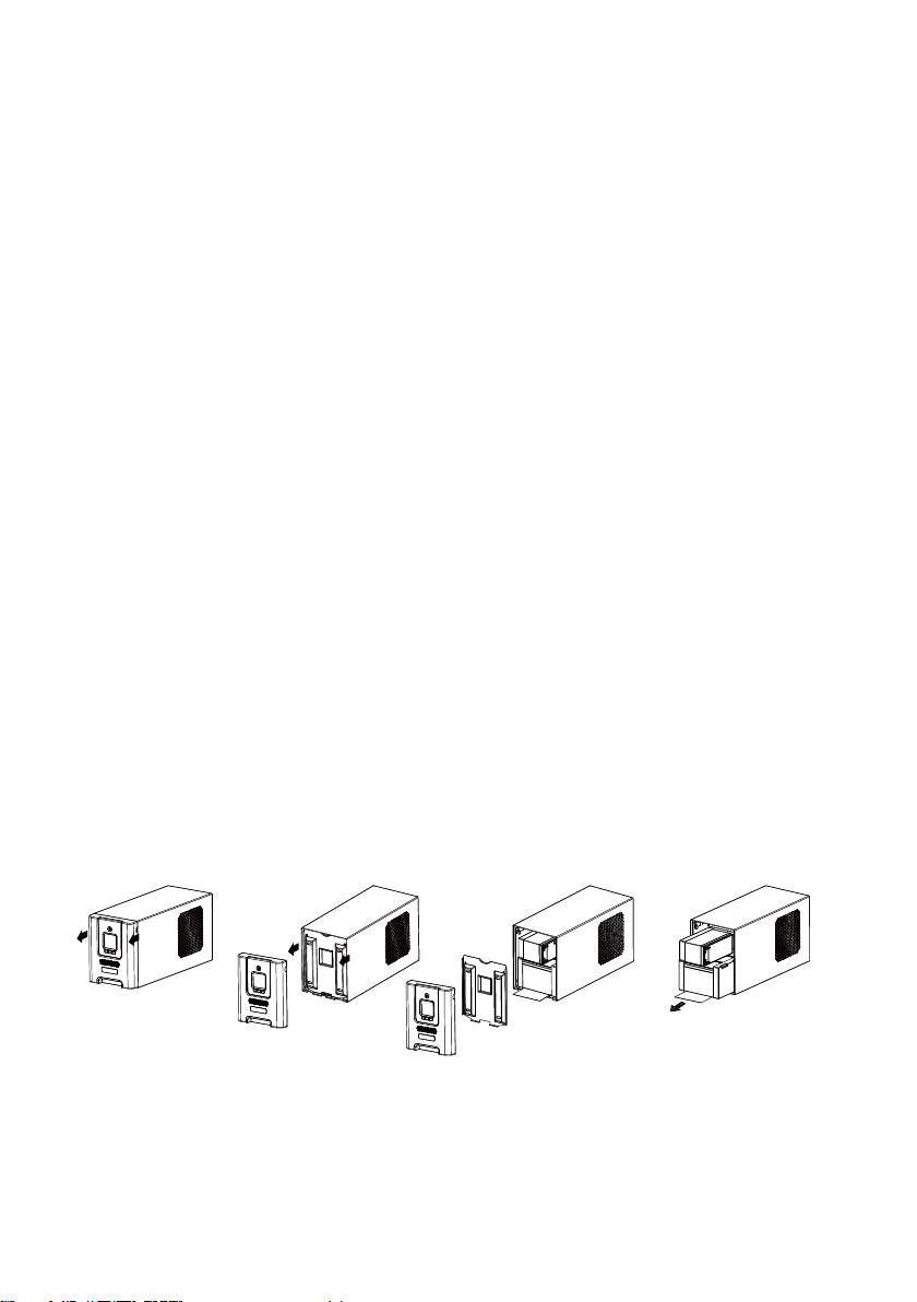
BATTERY REPLACEMENT PROCEDURE:
1. Turn off and unplug all connected equipment.
2. Turn the UPS off and unplug it from the AC power source.
3. Remove the front panel of the UPS.
4. Remove two screws from the battery compartment cover and slide the cover completely off of
the unit.
5. Remove the batteries from the compartment.
6. Disconnect the battery wires from the batteries.
7. Install the replace batteries by connecting the red wire (+) and black wire (-) to the same color
connectors from the battery pack.
8. Put the batteries back into the compartment.
9. Re-install the battery compartment cover and tighten the retaining screws.
10. Put the front panel back on the UPS.
11. Connect to AC power and charge the new batteries for up to 16 hours to insure a full charge.
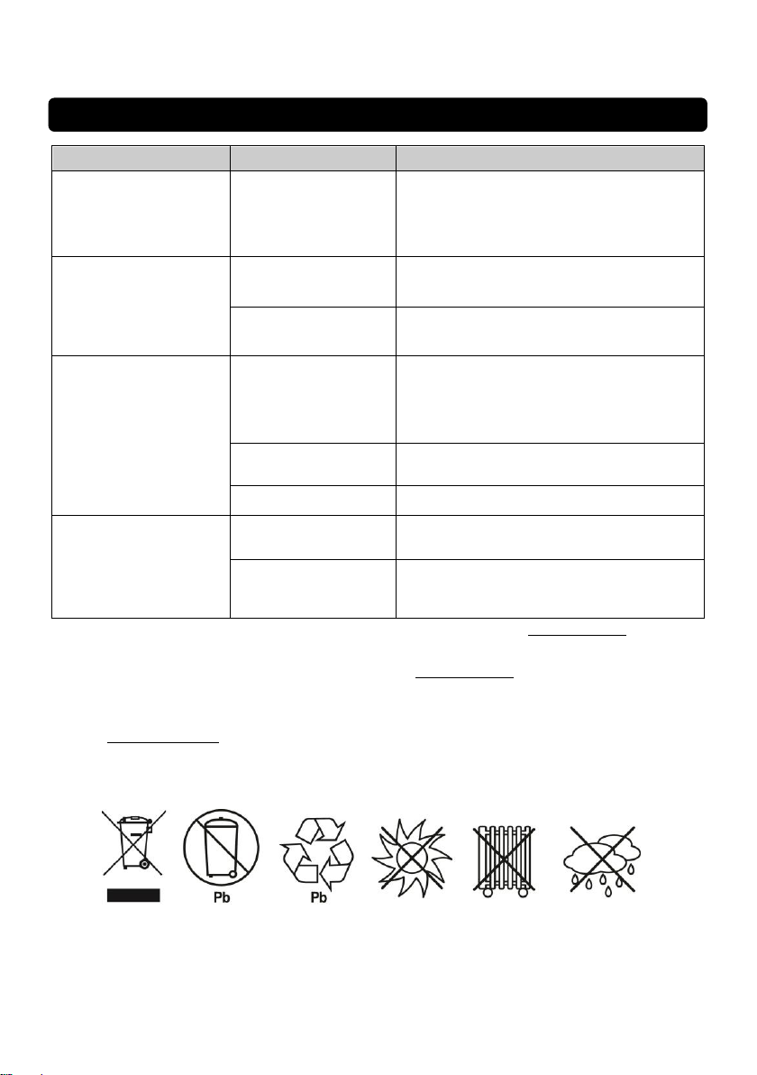
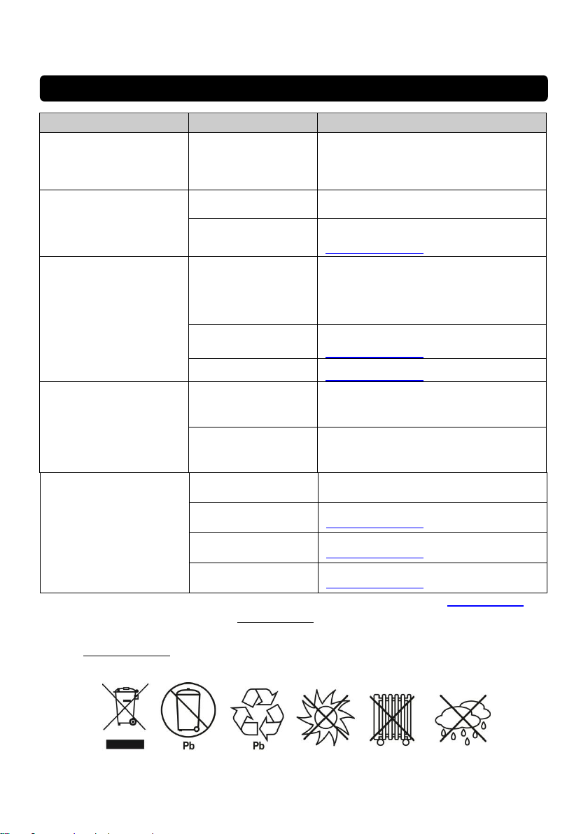
REMINDER: Batteries are considered HAZARDOUS WASTE and must be disposed of properly.
Almost any retailer that sells lead-acid batteries collects used batteries for recycling.
6
Page 7
1
2
4
5
6
7
8
9
10
11
12
13
14
3
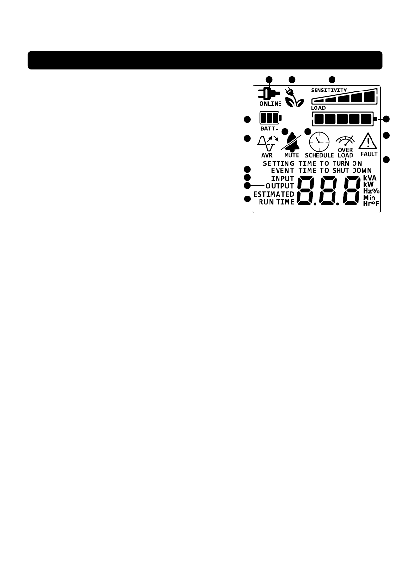
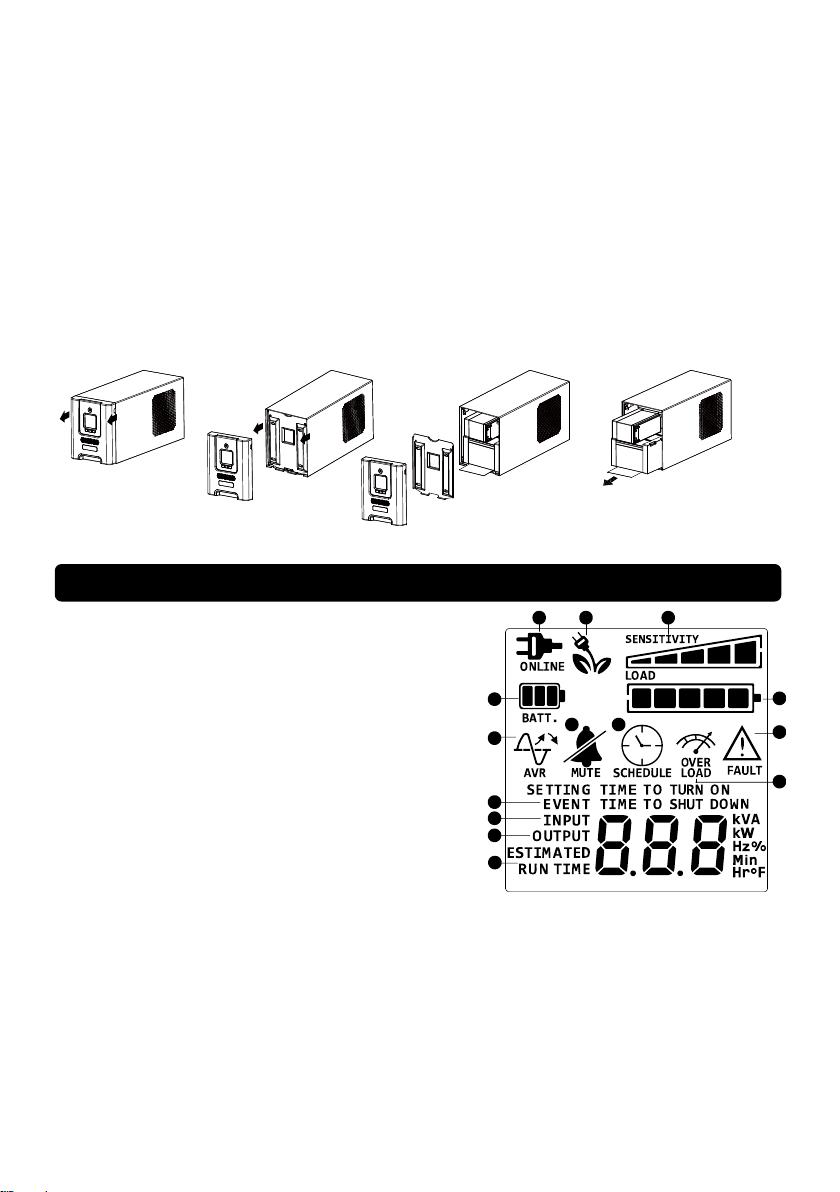
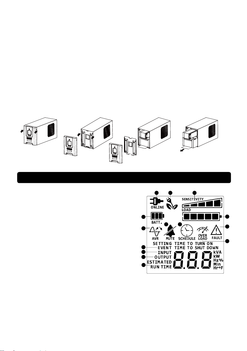
DEFINITIONS FOR ILLUMINATED LCD INDICATORS
1. ONLINE: The UPS is supplying utility power to connected
equipment.
2. BATTERY: During a severe brownout or blackout, this
icon appears and an alarm sounds (two short beeps
followed by a pause) to indicate the UPS is operating
from its internal batteries. During a prolonged brownout
or blackout, the alarm will beep rapidly every 1/2 second
(and the BATT.CAPACITY meter shows one 20%
capacity segment shaded. The capacity depends on how
much load added and the runtime left.) to indicate the
UPS’s batteries are nearly out of power. You should
save files and turn off your equipment immediately or
allow the software to shut the system down.
3. Energy-Saving: The UPS in energy-saving bypass
mode. When the utility power is normal and the battery is
fully charged, the UPS will go into energy-saving bypass mode automatically. See “CyberPower
GreenPower UPSTM Technology” section for more information.
4. LOAD capacity / Sensitivity setup: This meter displays the approximate output load level (in 20%
increments) of the UPS battery outlets. It can also be sensitivity setup meter if you are in Setup
mode. It is to control the sensitivity of the UPS to switch to Battery Mode by selecting UPS
shutdown voltage range. When the sensitivity is increased, the UPS will switch to Battery Mode
with less input power variation.
5. BATTERY capacity: This meter displays the approximate charge level (in 20% increments) of the
UPS’s internal battery. During a blackout or severe brownout, the UPS switches to battery power,
the BATTERY icon appears, and the charge level decreases.
6. FAULT: This icon appears if there is a problem with the UPS. Press the POWER button to turn off
the UPS.
F01: Battery Mode or AC/Utility Power Mode Overload fault (Shut off non-essential equipment. If
this solves the overload problem, the UPS will transfer to normal operation.)
F02: Battery Output Short fault (The connected equipment may have problems, please remove
them and check again.)
F03: Charger Fault (Contact CyberPower Systems for support.)
F04: Internal Fault (Contact CyberPower Systems for support.)
F05: Fan Abnormal (Contact CyberPower Systems for support.)
7. OVER LOAD: This icon appears and an alarm sounds to indicate the battery-supplied outlets are
overloaded. To clear the overload, unplug some of your equipment from the battery-supplied
outlets until the icon turns off and the alarm stops.
8. SCHEDULE: Users can setup the schedule to turn on and shut down the computer and UPS
through PowerPanel® Personal Edition software. The LCD display will show how much time is left
before the UPS will turn back on or shut down.
9. ESTIMATED RUNTIME: This displays the run time estimate of the UPS with current battery
capacity and load.
10. OUTPUT meter: This meter measure, in real time, the AC voltage that the UPS system is providing
to the computer, such as normal AC line mode, AVR mode, and battery backup mode. (Note: The
OUTPUT meter shows the status of the battery backup outlets in terms of load, frequency, and
voltage.)
7
Page 8

11. INPUT meter: This meter measures the AC voltage that the UPS system is receiving from the utility
wall outlet. The UPS is designed, through the use of automatic voltage regulation, to continuously
correct output voltage to connected equipment to a safe voltage output range. In the event of a
complete power loss, severe brownout, or over-voltage, the UPS relies on its internal battery to
supply consistent output voltage. The INPUT voltage meter can be used as a diagnostic tool to
identify poor-quality input power.
12. EVENT: This meter records the number of power outages.
13. MUTE: This icon appears whenever the UPS is in silent mode. The alarm does not beep during
silent mode until the battery reaches low capacity.
14. AVR (Automatic Voltage Regulation): This icon appears whenever your UPS is automatically
correcting low AC line voltage without using battery power. This is a normal, automatic operation of
your UPS, and no action is required on your part.
For more information about functions setup, please refer to the Function Setup Guide.
8
Page 9

TECHNICAL SPECIFICATIONS
Model
PR2200ELCDSL
PR2200ELCDSXL
PR3000ELCDSL
PR3000ELCDSXL
Capacity (VA)
2200VA/1980W
3000VA/2700W
Input
Frequency Range
50/60Hz +/-3 Hz (Auto Sensing)
AVR Function
Yes
Output
On Battery Output
Voltage
230Vac +/-10%
On Battery Output
Frequency
50/60Hz +/-1%
Overload Protection
On Utility: Circuit Breaker & Internal Current Protection
On Battery: Internal Current Limiting
Surge Protection
Lightning / Surge
Protection
Yes
Operating Temperature
+32F to 104F ( 0C to 40C )
Physical
Total # of UPS outlets
IEC x 9
Maximum
Dimensions(LxWxH)
221 x 170 x 432 mm
Weight (kg)
23.3
24.5
Battery
Battery
Sealed Maintenance Free Lead Acid Battery
Typical Recharge Time
8 hours
Charging Current(Max.)
1A
User Replaceable
Yes
Status Indicators
Indicators
Power On, LCD Display, Online, On Battery, Fault, Replace Battery
Audible Alarms
On Battery, Low Battery, Overload
Communication
PowerPanel® Business
Edition Software
Windows 10/8/7/Vista/XP/2000/Server 2003, Linux
Management
Self -Test
Yes
Auto-Charger
Yes
Auto-Restart
Yes
USB interface
Yes
Expansion Port
Yes
EPO Port
Yes
Certifications
Certifications
CE
9
Page 10
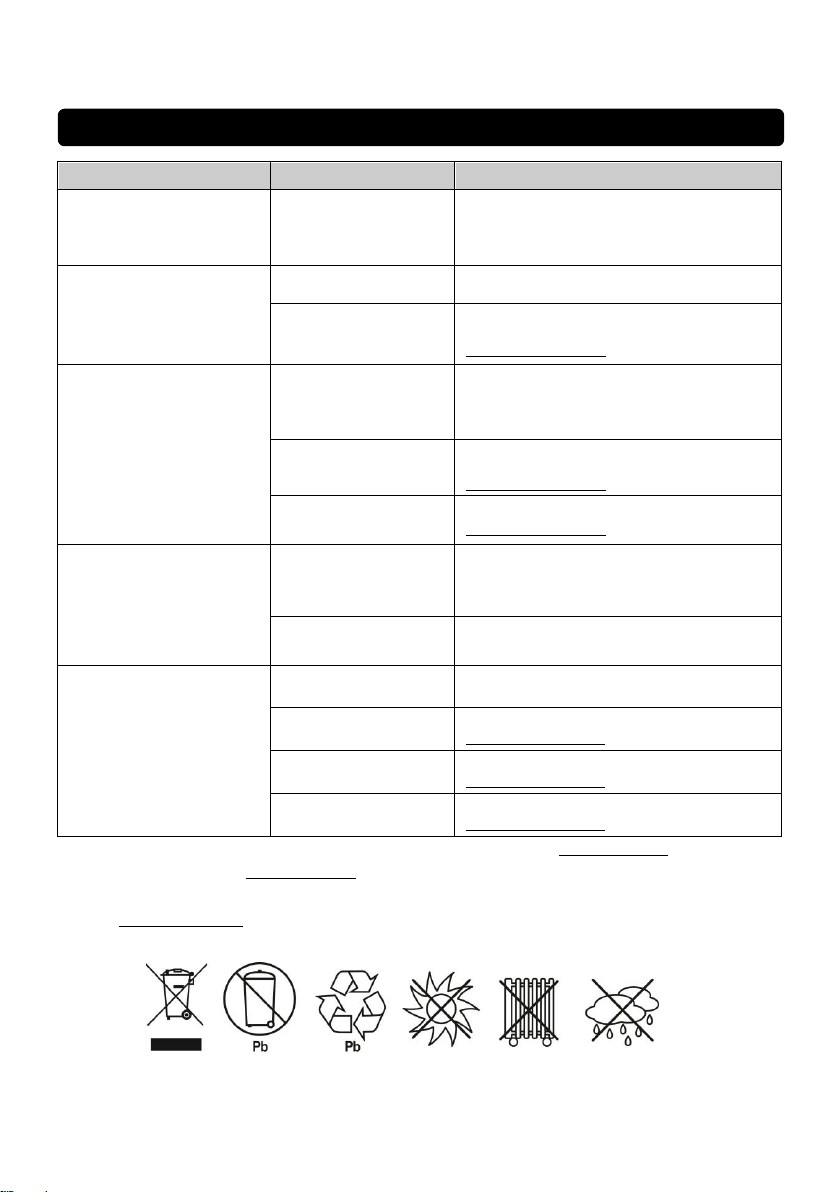
TROUBLESHOOTING
Problem
Possible Cause
Solution
Circuit breaker button is
projecting from the back of
the unit.
Circuit breaker has
tripped due to an
overload.
Turn the UPS off and unplug at least one
piece of equipment. Wait 10 seconds, reset
the circuit breaker by depressing the
button, and then turn the UPS on.
The UPS does not perform
expected runtime.
Battery not fully
charged.
Recharge the battery by leaving the UPS
plugged in.
Battery is slightly worn
out.
Contact CyberPower Systems about
replacement batteries at
[email protected]
The UPS will not turn on.
The on/off switch is
designed to prevent
damage by rapidly
turning it off and on.
Turn the UPS off. Wait 10 seconds and
then turn the UPS on.
The battery is worn
out.
Contact CyberPower Systems about
replacement batteries at
[email protected]
Mechanical problem.
Contact CyberPower Systems at
[email protected]
PowerPanel® Business
Edition is inactive.
The USB cable is not
connected.
Connect the USB cable to the UPS unit
and an open serial port on the back of the
computer. You must use the cable that
came with the unit.
The unit is not
providing
battery power.
Shutdown your computer and turn the
UPS off. Wait 10 seconds and turn the
UPS back on. This should reset the unit.
The fault LED is
illuminated.
Overload
Remove excessive load and restart the
UPS.
Output Short
Contact CyberPower Systems at
[email protected]
Battery Overcharge
Contact CyberPower Systems at
[email protected]
Over Temperature
Contact CyberPower Systems at
[email protected]
Additional troubleshooting information can be found at www.cpsww.eu
For more information, visit www.cpsww.eu or contact
Cyber Power Systems, Inc.
E-MAIL: [email protected]
All rights reserved. Reproduction without permission is prohibi
10
Page 11
DE
PR2200ELCDSL / PR3000ELCDSL
PR2200ELCDSXL / PR3000ELCDSXL
Bedienungsanleitung
11
Page 12

WICHTIGE SICHERHEITSHINWEISE
In dieser Anleitung finden Sie wichtige Hinweise, denen Sie bei der Installation und Wartung der USV
und der Batterien befolgen sollten! Bitte lesen Sie die Anleitung vollständig durch, bevor Sie das
System auspacken, installieren und in Betrieb nehmen. Folgen Sie den beschriebenen Anweisungen
sorgfältig während der Installation und des Betriebes der USV.
ACHTUNG! Diese USV muss an einen geerdeten Stromkreis angeschlossen werden, der mit einer
Sicherung oder einem Stromkreisunterbrecher abgesichert ist. Schließen Sie die USV keinesfalls an
einen Stromkreis an, der nicht geerdet ist. Wenn Sie dieses System entladen müssen, trennen Sie die
USV vom Stromkreis und schalten Sie sie aus.
ACHTUNG! NUTZEN SIE DIESE USV KEINESFALLS FÜR MEDIZINISCHE ODER
LEBENSERHALTENDE GERÄTE! CyberPower verkauft keine Geräte für medizinische oder
lebenserhaltende Anwendungen. Nutzen Sie diese USVs unter keinen Umständen bei Geräten, die in
irgendeiner Form lebenserhaltende oder medizinische Systeme oder Patientenpflege unterstützen.
ACHTUNG! Die Batterien in der USV versorgen im Innern der USV Teile mit gefährlicher Spannung,
auch wenn das Geräte nicht an einen Stromkreis angeschlossen ist.
ACHTUNG! Um Feuer und Stromschläge zu vermeiden, installieren Sie die USV in trockenen
Innenräumen ohne Kontakt zu stromleitenden Geräten oder Oberflächen. (Bitte beachten Sie die
Hinweise für die Vorgaben zu Temperatur- und Luftfeuchte).
ACHTUNG! Um das Risiko für elektrische Schläge zu verringern, öffnen Sie keinesfalls die USV. Bis
auf die Batterie befinden sich keine zu wartenden Teile in der USV. Öffnen Sie nur die
Batterie-Abdeckung um die Batterie zu warten.
ACHTUNG! Um elektrische Schläge zu vermeiden, schalten Sie die USV ab und trennen Sie sie vom
Stromkreis, bevor Sie die Batterie warten.
ACHTUNG! NICHT IN DER NÄHE VON AQUARIEN AUFSTELLEN! Um die Gefahr von
Kurzschlüssen zu vermeiden, stellen Sie die USV nicht in der Nähe von Aquarien auf.
Kondensierendes Wasser könnte mit metallischen oder elektrischen Teilen zusammenkommen und
einen Kurzschluss verursachen.
USV IM BETRIEB KEINEN ERSCHÜ TTERUNGEN AUSSETZEN! Um die Gefahr von Feuer oder
elektrischen Schlägen zu vermeiden, darf die USV nicht in Transportmitteln wie zB. Flugzeugen oder
Schiffen verwendet werden. Innerhalb der USV können physikalische Schläge, starkes Ruckeln oder
Vibrationen sowie eine feuchte Umgebung einen Kurzschluss verursachen.
INSTALLATION IHRER USV
AUSPACKEN
Der Karton sollte folgende Teile beinhalten:
(1) eine USV; (2) ein Emergency Power Off Kabel (grau); (3) ein serielles Kabel; (4) ein USB-Kabel;
(5) eine Bedienungsanleitung; (6) Anleitung Setup Einstellungen; (7) vier Stromkabel
Die PowerPanel® Business Edition-Software finden Sie auf unserer Website. Bitte besuchen Sie
www.cyberpower.com und gehen Sie zum kostenlosen Download in den Software-Bereich.
Ü BERBLICK
Die PR2200/3000ELCDSL, PR2200/3000ELCDSXL hat eine automatische Spannungsregulierung bei
instabiler Versorgungsspannung. Die PR2200/3000ELCDSL, PR2200/3000ELCDSXL bietet einen
Ü berspannungsschutz von 405 Joule und schaltet bei Stromausfall auf batterie-gepufferte
Stromversorgung um. Die PR2200/3000ELCDSL, PR2200/3000ELCDSXL liefert konstanten Strom für
12
Page 13
Communication Ports
See Installati on Instruction s
Supply
TVSS GND
Before Con necting ToThe
Provides SNM P Card Communication
Expansion Port
Input
+
MUTEDISPL AY SETUP
ENTER
+
48VDC 70A MAX
1
2
4
5
6
7
7
8
9
10
11
12
13
3
Ihren Computer und kann mit der mitgelieferten Software Ihren Computer im Falle eine Stromausfalles
geregelt herunter fahren.
WIE SIE DEN STROMBEDARF IHRER GERÄ TE ERMITTELN
1. Stellen Sie sicher, dass der gesamte Volt-Amp (VA) Bedarf Ihres Computers, Monitors und
Peripheriegeräte 2200VA/3000VA nicht übersteigen.
2. Stellen Sie sicher, dass die an die USV angeschlossenen Geräte insgesamt nicht die angegeben
Kapazität Ihrer USV übersteigt. (2200VA/1980W für for PR2200ELCDSL/PR2200ELCDSXL,
3000VA/2700W für for PR3000ELCDSL/PR3000ELCDSXL). Sollte die angegebene Kapatzität
überschritten werden, schaltet die USV wegen Überlast automatisch ab und der
Stromkeisunterbrecher spricht an.
GRUNDFUNKTIONEN
Beschreibung
1. Netzsschalter
Haupt-Ein-/Ausschalter für die angeschlossenen Geräte.
2. Funtionsanzeige
Diese LED ist unterhalb des Netzschalters und leuchtet auf, wenn das Gerät eingeschaltet und
an den Ausgängen keine Störungen anliegen.
3. LCD-Anzeige
Mikroprozessorgesteuertes und hintergrundbeleuchtetes High-Resolution-LCD, das alle
Informationen der USV mittels Piktogrammen und Texten anzeigt. Für die detaillierte Beschreibung
beachten Sie bitte die Angaben unter „ERKLÄRUNG DER LCD-ANZEIGE“.
4. Herunter-/Display-Taste
Die Taste dient zur Auswahl der LCD-Anzeige von Eingangsspannung, Ausgangsspanung und der
verbleibenden Batterielaufzeit. Kurzer Tastendruck: Herunterscrollen des Funktionsmenüs.
13
Page 14
Drücken der Taste 2 Sekunden: Das Display wird auf Immer an (Always-On) geschaltet. Befindet
sich die USV im Netztbetrieb wird das Display damit ein/ausgeschaltet.
Weitere Informationen zu den Funktionsmenüs finden Sie im beiliegenden Function Setup Guide.
5. Hoch-/Stumm-Taste
Ein kurzer Druck auf die Taste scrollt das Funktionsmenü der USV herauf. Mit Druck der Taste für 2
Sekunden wird der Alarm stummgeschaltet.
Weitere Informationen zur Hoch-/Stumm-Taste finden Sie im beiliegenden Function Setup Guide.
6. Enter/Setup Taste
Drücken der Taste für 2 Sekunden öffnet das Setup-Menü und ermöglicht die Auswahl der
Optionen zur Konfiguration der USV.
Weitere Informationen zur Enter-/Setup-Taste finden Sie im beiliegenden Function Setup Guide.
7. Batterie- und Ü berspannungsschutz gesicherte Steckdosen
Diese USV verfügt über neun Batterie-gepufferte und gegen Ü berspannung gesicherte Ausgänge
mit denen die angeschlossenen Verbraucher bei Störungen und Stromausfall vorüberghehend
versorgt werden.
8. Serieller/USB PC-Anschluss
Dieser Anschluss ermöglicht eine Verbindung an einen PC über eine Serieller/USB-Schnittstelle.
HINWEIS: Es kann nur ein Anschluss zur Kommunikation und der Steuerung der USV genutzt
werden
9. EPO Port
Zur Nutzung verwenden Sie das beiliegenden grau EPO Kabel. Befolgen Sie die Installation
entsprechend dem Diagramm. Der EPO Schalter sollte entfernt der USV Zone platziert warden. Im
Falle eines Notfalls lassen sich somit die von der USV versorgten Geräte sofort von der
Energieversorgung trennen
10. SNMP/HTTP Netzwerkschacht
Entfernen Sie die Abdeckung zur Installation der optionalen RMCARD zur Fensteuerung und
erweiterten Management der USV über das Netztwerk.
11. Anschluss für externes Batteriemodul (außer PR2200ELCDSL / PR3000ELCDSL)
Dient zum Anschließen eines optionalen externen CyberPower-Batteriemoduls (BP48VPT01) für
eine längere Laufzeit.
12. Sicherungsschalter
Auf der Rückseite befindet sich der Sicherungsautomat zum Schutz bei Überlast oder Fehlfunktion.
13. Stromanschluss
Schließen Sie die USV mit dem Anschlusskabel an eine ordnungsgemäße und geerdete
Steckdose an.
14
Page 15

INSTALLIEREN DER USV
1. Sie können Ihre neue USV gleich nach dem Erhalt nutzen. Zuvor empfehlen wir Ihnen jedoch, die
Batterien für mindestens acht Stunden aufzuladen, um sicher zu stellen, dass die Batterie ihre
maximale Kapazität erreicht hat. Während des Transportes oder der Lagerung kann es zu teilweiser
Entladung gekommen sein. Um die Batterien aufzuladen, schließen Sie die USV einfach an Ihr
Stromnetz an. Das Aufladen der Batterien erfolgt auch, wenn das Gerät abgeschaltet ist.
Hinweis: Diese USV verfügen über ein Schutzsystem das ein Einschalten beim Transport verhindert.
Zum ersten Einschalten muss die USV mit dem Netzkabel an das Stromnetz angeschlossen werden.
2. Wenn Sie die mitgelieferte Software nutzen möchten, verbinden Sie USV und PC mit dem
mitgelieferten USB-Kabel.
3. Schließen Sie alle externen Geräte, wie Computer, Monitor oder externe Datenspeichergeräte, an
die Batterie-gepufferten Steckdosen der USV an, wenn diese ausgeschalten und selbst nicht
angeschlossen sind. Schließen Sie KEINESFALLS Laser-Drucker, Kopierer, Heizlüfter, Staubsauber,
Aktenvernichter oder große elektrische Stromverbraucher an die USV an. Die Leistung dieser Geräte
übersteigt die verfügbare Abgabeleistung der USV und führt unter Umständen zu Beschädigungen
der USV.
4. Schließen Sie die USV an eine vorschriftsgemäß angeschlossene und geerdet Steckdose an. Stellen
Sie sicher, dass die Leitung über einen geeigneten Sicherungsschutz verfügt und dass an dieser
Steckdose keine weiteren großen Verbraucher, wie z.B. Heizlüfter oder Staubsauger, angeschlossen
sind.
5. Betätigen Sie den Einschaltknopf, um die USV einzuschalten. Die Kontroll-LED leuchtet auf und das
Gerät gibt ein kurzes akustisches Signal ab.
6. Ist eine Überlast an die USV angeschlossen ertönt ein langanhaltendes akustisches Signal. Schalten
Sie die USV ab und warten Sie nach dem Entfernen von mindestens einem Verbraucher 10
Sekunden bevor Sie die USV wieder einschalten. Überprüfen Sie den Stromkreis-Unterbrecher, und
re-aktivieren Sie diesen, falls er angesprochen haben sollte.
7. Ihre USV ist mit einer automatischen Lade-Kontrolle versehen. Sobald die USV selbst an ein
Stromnetz angeschlossen ist, beginnt Sie automatisch die Batterien zu laden, auch wenn das Gerät
selbst nicht eingeschaltet ist.
8. Um eine optimale Ladung der Batterien aufrecht zu erhalten, lassen Sie die USV ständig an Ihr
Stromnetz angeschlossen.
9. Sollten Sie die USV über einen längeren Zeitraum nicht nutzen, lagern Sie diese mit voll
aufgeladenen Batterien und laden Sie diese in einem Abstand von ca. drei Monaten immer wieder
auf, um die Batterien vor Schaden zu bewahren.
CYBERPOWER GREENPOWER USV TECHNOLOGIE
CyberPower’s Green-IT Engagement
CyberPower engagiert sich bei der Entwicklung von Green-IT Produkten und bringt
im gesamten Produktions- und Geschäftsumfeld Green-IT Technologien zum
Einsatz, was auch durch die Mitgliedschaft der Climate Savers Computing Initiative
(CSCI), der Einhaltung zur Reduktion gefährlicher Stoffe (RoHS), der
Entsorgungsrichlinien für elektrischen und elektonischen Schrott (WEEE), wie auch
der Zertifizierung nach ISO 14001 und IECQ QC080000 zum Ausdruck kommt.
CyberPower versichert, fortschrittliche und umweltschonende Produkte zu fertigen,
um so zu einem der führenden umweltfreundlichen Unternehmen in der USV-Industrie zu werden.
15
Page 16

Reduzierung der Energiekosten mittels der GreenPower UPSTM Technologie
CyberPower’s Ziel ist es nicht nur umweltfreundliche Geräte herzustellen, sondern auch dem
Anwender die besten Vorteile zu verschaffen. Das fortschrittiche Energie-Spar-Design optimiert die
Effizienz und verhindert die Energieverschwendung. Als Resultat wird der Anwender durch die
Nutzung der GreenPower UPSTM Technologie mit erheblichen Energiekosteneinsparungen belohnt.
BATTERIEAUSTAUSCH
ACHTUNG! Lesen und befolgen Sie unbedingt die WICHTIGEN SICHERHEITSANWEISUNGEN
bevor Sie die Batterien warten bzw. wechseln. Tun Sie dies nur unter Aufsicht und nach
Anweisung von qualifizierten Fachleuten.
ACHTUNG! Beim Ersetzen der Batterien nur mit der gleichen Art und Anzahl der Batterien oder Akkus
ersetzen.
ACHTUNG! Nutzen Sie ausschließlich die vorgeschriebenen Batterien. Wenden Sie sich diesbezüglich
ggfls. an Ihren Händler.
ACHTUNG! Im Umgang mit Batterien besteht die Gefahr eines elektrischen Schlages. Werfen Sie die
Batterien auf keinen Fall in ein Feuer, da sie explodieren könnten. Befolgen Sie die örtlichen
Vorschriften für eine ordentliche Entsorgung.
ACHTUNG! Ö ffnen oder beschädigen Sie die Batterie keinesfalls. Austretendes Elektrolyt kann giftig
sein und Haut und Augen verätzen.
ACHTUNG! Bei Kurzschluss der Batterie treten sehr hohe Kurzschlussströme auf und es besteht die
Gefahr eines elektrischen Schlages. Beachten Sie folgende Vorsichtsmaßnahmen, bevor sie die
Batterien warten:
1. Legen Sie Armbanduhr, Ringe und alle metallischen Teile ab.
2. Verwenden sie ausschließlich Werkzeuge mit Isolationsgriffen.
3. Legen Sie KEINESFALLS Werkzeuge oder metallische Teile auf die Batterie oder in das
Batteriefach.
4. Trennen Sie die Ladequelle vor dem Anschließen oder Abtrennen der Batterieklemmen.
5. Tragen Sie keine Gummihandschuhe und Gummistiefel.
6. Vergewissern Sie sich, dass die Batterie nicht versehentlich geerdet ist. Entfernen Sie etwaige
Erdungen. DIE ERDUNG EINER BATTERIE KANN ZU EINEM ELEKTRISCHEN SCHLAG
FÜ HREN! Die Wahrscheinlichkeit eines solchen Schlages kann verringert werden, wenn eine
versehentliche Erdung während der Installation oder Wartung entfernt wird (diese trifft für USV und
externe Batterieerweiterungen zu, die nicht an eine geerdete Spannungsversorgung
angeschlossen sind.)
VORSICHT - EXPLOSIONSGEFAHR, WENN DIE BATTERIE DURCH EINEN FALSCHEN TYP
ERSETZT WIRD. GEBRAUCHTE BATTERIEN GEMÄSS DEN ANWEISUNGEN ENTSORGEN.
WECHSELN DER BATTERIEN:
1. Schalten Sie die USV ab und trennen Sie alle angeschlossenen Verbraucher.
2. Trennen Sie die USV vom Netz.
3. Entfernen Sie die Frontblende von der USV.
4. Entfernen Sie die Schrauben von der Batteriebadeckung und ziehen Sie diese von dem Gerät ab.
5. Entfernen Sie die Batterien aus dem Schacht.
6. Trennen Sie die Batterie-Stecker von den Batterien.
7. Installieren Sie die Ersatzbatterien, indem Sie die Kabel (bestehend aus einem roten Kabel und
16
Page 17
1
2
4
5
6
7
8
9
10
11
12
13
14
3
einem schwarzer Kabel) mit dem Stecker an die Batterien verbinden. Verbinden Sie das Ende der
Batteriekabel wieder und verriegeln den Steckverbinder.
8. Setzen Sie die Ersatzbatterien wieder in den Schacht.
9. Befestigen Sie die Batterieabdeckung wieder und schrauben diese fest.
10. Setzen Sie nun die Frontblende wieder an die USV an.
11. Laden Sie die Batterien in der USV für 8-12 Stunden, um eine volle Aufladung der Batterien zu
gewährleisten.
Hinweis: Der Akku besitzt eine externe Sicherung.
HINWEIS: Batterien sind als UMWELTGEFÄHRDENDER ABFALL eingestuft und müssen
vorschriftsgemäß entsorgt warden!
ERKLÄ RUNG DER LCD-ANZEIGE
1. ONLINE: Die USV ist im Netzbetrieb und versorgt das
angeschlossene Equipment mit Netzspannung.
2. BATTERIE: Dieses Symbol wird bei bei starken
Stromschwankungen bzw. Stromausfall angezeigt,
und gleichzeitig ertönt ein akustisches Warnsignal (2
x kurzes Piepsen im Wechsel mit
einer Pause). Das zeigt an, dass die USV in den
Batterie-Modus umgeschaltet hat. Während eines
Stromausfalls oder länger anhaltender
Unterspannung ertönt jede halbe Sekunde ein
Signalton (In der Anzeige wird die Akkukapazität
„BATT.CAPACITY“ in 20% Schritten angezeigt). Die
Laufzeit ist abhängig von der Last.
3. Energy-Saving: Die USV ist im Energiesparmodus. Weitere Informationen dazu finden Sie in der
Rubrik “CyberPower GreenPower UPSTM Technologie”.
4. LASTMESSER / Sensitivität Setup: Hier wird die Last der USV in Abstufungen von jeweils 20%
angezeigt. Über die Einstellung „Sensitivität“ kann festgelegt werden, wann die USV in den
Batteriebetrieb umschaltet. Je höher die Sensitivität eingestellt ist, umso eher schaltet die USV in
Batteriebetrieb.
5. LADEZUSTANDSMESSER: Diese Anzeige gibt einen Überblick über denLadezustand der
Batterie in Abstufungen von jeweils 20%.
17
Page 18

6. FEHLER: Gibt es Störungen in der USV, wird dieses Icon aktiviert. Zum Ausschalten der USV
drücken Sie die POWER Taste.
F01: BATTERIEBETRIEB oder AC/Netzbetrieb Überlastfehler (Schalten Sie nicht benötigte
Geräte aus. Wenn dies das Überlastungsproblem löst, wechselt die USV in den normalen
Betrieb.)
F02: Fehler BATTERIE Ausgangskreis (Die angeschlossenen Geräte haben möglicherweise
Probleme. Bitte entfernen Sie sie und überprüfen Sie sie erneut.)
F03: Fehler Ladekreis (Kontaktieren Sie CyberPower Systems für Service Support)
F04: Interner Elektronikfehler (Kontaktieren Sie CyberPower Systems für Service Support)
F05: Fehler Lüfter (Kontaktieren Sie CyberPower Systems für Service Support)
7. Ü BERLAST: Dieses Icon wird dann sichtbar, und ein akustisches Signal ertönt, wenn die
angeschlossene Last an den batteriegepufferten Steckdosen die Kapazität der USV übersteigt.
Um den Alarm abzuschalten, entfernen Sie schrittweise einige angeschlossene Endgeräte.
8. PLANUNGEN: Über die PowerPanel® Personal Edition Software können automatische
Ein-Auschaltfunktionen der USV programmiert werden. Das LCD Display zeigt an, wann die USV
sich abschalten wird.
9. ERWARTETE LAUFZEIT: Auf dieser Anzeige ist zu sehen, wie lang die USV bei verbleibender
Batterieladung die Steckdosen mit Strom versorgt.
10. AUSGANGS-Spannungsmesser: Dieser Spannungsmesser zeigt die Spannung an, mit der die
Endgeräte versorgt warden. Das geschieht auch wenn AVR aktiv ist bzw. die USV im
Batterie-Modus fährt. (Hinweis: Hier wird der Status wie Last, Frequenz und die Spannung des
USV Ausgangs angezeigt)
11. EINGANGS-Spannungsmesser: Diese Messung zeigt die eingehende Wechselspannung der
Stromversorung an. Dank AVR (automatische Spannungsregelung) korrigiert die USV
kontinuierlich den Spannungsbereich für die an die Ausgangsspannung angeschlossenen Geräte.
Im Falle eines Stromausfalls, starken Spannungsschwankungen oder Überspannungen liefert die
USV dank Batteriepufferung weiterhin eine gleichmäßige Ausgangsspannung.
12. EVENT: Zählerfunktion von Stromstörungen.
13. RUHE-MODUS: Dieses Icon ist dann sichtbar, wenn der akkustische Alarm deaktiviert ist. Dieser
schaltet sich automatisch ein, wenn die Kapazität der Batterie zu Ende geht.
14. AVR (Automatic Spannungs (Voltage) Regulierung): Dieses Icon wird sichtbar, wenn die USV
die AVR aktiviert hat und die Endgeräte aus den Batterien versorgt. Dies ist eine normale
Funktion, die ihrerseits keine Maßnahmen erfordert.
Weitere Informationen finden Sie im Anhang Anleitung Setup Einstellungen.
Bitte beachten: „Load“ = Auslastung der USV
18
Page 19

TECHNISCHE SPEZIFIKATIONEN
Modell
PR2200ELCDSL
PR2200ELCDSXL
PR3000ELCDSL
PR3000ELCDSXL
Kapazität (VA)
2200VA/1980W
3000VA/2700W
Eingang
Eingangsspannung
230Vac +/-20%
Frequenzbereich
50/60Hz +/-3 Hz (autosensorik)
AVR Funktion
Ja
Ausgang
Ausgangsspannung im
Batteriebetrieb
230Vac +/-10%
Ausgangsfrequenz im
Batteriebetrieb
50/60Hz +/-1%
Ü berlastschutz
USV: Stromkreisunterbrechung & Interne Strombegrenzung,
Batterie: Interne Strombegrenzung
Spannungsschutz
Blitzschutz/Überspannung
Ja
Betriebstemperatur
0C to 40C
Aufmaße
Anzahl der Steckdosen
IEC x 9
Maximale Abmessungen
(LxWxH)
221 x 170 x 432 mm
Gewicht (kg)
23.3
24.5
Batterien
Batterien
Wartungsfreie Blei-Gel-Akkumulatoren
Typische Ladezeit
8 Stunden
Ladestrom (max.)
1A
Durch Anwender während
Betrieb austauschbar
Ja
Status Anzeigen
Anzeigen LED/LCD
Funktion An, Netzbetrieb, Batteriebetrieb, FEHLER,
Batteriewechsel, LCD-Anzeige
Akustische Signale
Batteriebetrieb, Batterie schwach, Ü berlast
Kommunikation
PowerPanel® Business Edition
Software
Windows 10/8/7/Vista/XP/2000/WindowsServer, Linux
Management
Selbst-Test
Ja
Automatische Aufladung
Ja
Auto-Neustart
Ja
USB Anschluss
Ja
SNMP/HTTP Netzwerkschacht
Ja
EPO Port
Ja
Zertifizierung
Zertifizierung
CE
19
Page 20
FEHLERSUCHE
Problem
Mögliche Ursache
Lösung
Sicherungsschalter an
de Rückseite hat
ausgelöst.
Der StromkreisUnterbrecher hat
wegen
Ü berlast
angesprochen.
Schalten Sie die USV ab und entfernen sie
mindestens ein Endgerät. Warten Sie zehn
Sekunden und drücken dann den
Stromkreis-Unterbrecher-Taster wieder
hinein. Schalten Sie nun die USV wieder ein.
Die USV bringt nicht die
erwartete Laufzeit.
Batterien sind nicht
voll geladen.
Laden Sie die Batterien wieder auf, indem
Sie die USV am Stromnetz angeschlossen
belassen.
Batterien sind
aufgebraucht.
Kontaktieren Sie CyberPower Systems für
Austauschbatterien unter.
Die USV läßt sich nicht
einschalten.
Der Ein-/Ausschalter
ist so konzipiert, dass
er Schaden durch zu
schnelles Ein- und
Ausschalten
verhindert.
Schalten Sie die USV aus und warten Sie 10
Sekunden bevor Sie sie wieder einschalten.
Die Batterien sind
aufgebraucht.
Kontaktieren Sie CyberPower Systems für
Austauschbatterien unter.
Ein mechanisches
Problem liegt vor.
Kontaktieren Sie CyberPower Systems unter.
PowerPanel® Business
Edition ist inaktiv.
Das USB-Kabel ist
nicht richtig
angeschlossen.
Ü berprüfen Sie den Anschluss erneut und
verwenden Sie nur die mitgelieferten Kabel.
Die USV liefert keinen
Batteriestrom.
Schalten Sie die USV ab und nach 10
Sekunden wieder ein. Damit sollte die USV
zurückgesetzt sein und die Verbindung zum
PC wieder stehen.
Weitere Fehleranalyse-Informationen finden die auf der Seite: www.cpsww.eu
Für weitere Informationen besuchen Sie unser Webseite www.cpsww.eu oder kontaktieren Sie uns
unter:
Cyber Power Systems, Inc.
E-MAIL: [email protected]
Alle Rechte vorbehalten. Vervielfältigung ist ohne Erlaubnis verboten.
20
Page 21
IT
PR2200ELCDSL / PR3000ELCDSL
PR2200ELCDSXL / PR3000ELCDSXL
Manuale utente
21
Page 22

ISTRUZIONI DI SICUREZZA IMPORTANTI
Il presente manuale contiene istruzioni importanti che devono essere osservate durante l’installazione
e la manutenzione del dispositivo e delle batterie. Leggere attentamente questo manuale prima di
togliere l’apparecchio dalla confezione, di installarlo e/o di farlo funzionare.
ATTENZIONE! L’UPS deve essere collegato a una presa di corrente in C.A. (corrente alternata) dotata
di messa a terra, con fusibile di protezione o interruttore di circuito. NON installare l’UPS in una presa
non dotata di messa a terra. Se si desidera spegnere completamente il dispositivo, spegnere l’UPS e
scollegare il cavo di alimentazione dalla presa di corrente.
ATTENZIONE! NON UTILIZZARE CON APPARECCHIATURE O EQUIPAGGIAMENTI MEDICI
CyberPower Systems non vende prodotti per applicazioni di carattere medico o assistenziale. NON
utilizzare in nessuna circostanza che andrebbe a interferire con il funzionamento o la sicurezza di un
apparecchio o un’applicazione in campo medico o di strumenti destinati alla cura di un paziente.
ATTENZIONE! La batteria può alimentare componenti pericolosi in funzione all’interno dell’UPS anche
quando l’alimentazione in C.A. in ingresso non è collegata.
ATTENZIONE! Per evitare il rischio di incendio o di shock elettrico, installare il dispositivo in ambiente
chiuso con livelli di temperatura e di umidità controllati, al riparo da contaminanti conduttivi. (Consultare
le specifiche per conoscere l’intervallo di temperatura e umidità accettabili).
ATTENZIONE! Per limitare il rischio di folgorazione, non asportare il coperchio, tranne nel caso di
sostituzione della batteria. All’interno, ad eccezione della batteria, non sono presenti componenti
sostituibili dall’utente. La sostituzione delle batterie deve essere eseguita da operatori specializzati.
ATTENZIONE! Per evitare rischi di folgorazione, spegnere l’unità e disinserirla dalla presa in C.A.
prima di sostituire la batteria o installare un componente di un computer collegato.
ATTENZIONE! NON UTILIZZARE L’UPS PER O NELLE VICINANZE DI ACQUARI! Per
ridurre il rischio di incendio, non utilizzare il dispositivo per o nelle vicinanze di acquari. La condensa
prodotta dall’acquario può entrare in contatto con i componenti elettrici in metallo e provocare un corto
circuito.
NON UTILIZZARE L’UPS IN ALCUN MEZZO DI TRASPORTO! Per evitare rischi di folgorazione e/o
incendi, non utilizzare il dispositivo su mezzi di trasporto quali nevi o aeroplani. Le vibrazioni indotte
durante il trasporto e le condizioni ambientali, potrebbero causare corto circuiti
ESTRAZIONE DALLA CONFEZIONE
La confezione dovrebbe contenere i seguenti accessori:
(1) alimentatore continuo di elettricità x 1; (2) Cavo di Spegnimento di Emergenza grigio (EPO) x 1;
(3) Cavo Seriale x 1; (4) cavo USB (tipo A+B) x 1 (5) Manuale utente x 1; (6) Guida per la
configurazione delle funzioni x 1; (7) Cavo di alimentazione x 4
* Il software PowerPanel® Business Edition è disponibile sul nostro sito Web. Visita
www.cyberpower.com e vai alla sezione Software per il download gratuito.
PANORAMICA GENERALE
I modelli PR2200/3000ELCDSL, PR2200/3000ELCDSXL sono dotati di regolazione automatica della
tensione (AVR) per una corretta gestione della di rete di ingresso. Tutti i dispositivi hanno una
INSTALLAZIONE UPS
22
Page 23
Communication Ports
See Installati on Instruction s
Supply
TVSS GND
Before Con necting ToThe
Provides SNM P Card Communication
Expansion Port
Input
+
MUTEDISPL AY SETU P
ENTER
+
48VDC 70A MAX
1
2
4
5
6
7
7
8
9
10
11
12
13
3
protezione da sovratensioni di 405 Joule ed alimentano i dispositivi connessi utilizzando le batterie
durante le interruzioni. Gli UPS PR2200/3000ELCDSL, PR2200/3000ELCDSXL garantiscono
un’alimentazione regolare al vostro computer e sono dotati di un software che provvede a salvare le
sessioni di lavoro e a spegnere i computer durante un’interruzione di corrente della rete AC.
COME STABILIRE IL FABBISOGNO DI CORRENTE DELLE PROPRIE
APPARECCHIATURE
1. Accertarsi che il fabbisogno totale Volt-Amp (VA) di computer, monitor e periferiche collegate non
superi 2200VA/3000VA.
2. Accertarsi che le apparecchiature collegate alle quattro prese alimentate da batteria e protette da
picchi di corrente temporanea, non superino la capacità prevista per l’UPS (2200VA/1980W per il
modello PR2200ELCDSL / PR2200ELCDSXL, 3000VA/2700W per il modello PR3000ELCDSL /
PR3000ELCDSXL). In caso di superamento delle capacità stimate dell’unità, si può verificare una
situazione di sovraccarico che causa lo spegnimento del dispositivo e l’intervento del fusibile di
protezione.
FUNZIONI BASE
DESCRIZIONE
1. Interruttore di corrente
Utilizzato come interruttore di accensione/spegnimento principale per apparecchi collegati alle
prese di corrente alimentate dalle batterie.
2. Indicatore stato di accensione
Questo LED si trova sotto il pulsante di accensione. Si illumina quando l’UPS sta erogando
erogando corrente, in assenza di sovracorrente momentanea o picchi di tensione.
3. Display LCD
SI visualizzano messaggi ed icone relative allo stato di funzionamento e di configurazione dell’UPS.
Per ulteriori informazioni si prega di consultare il paragrafo “Definizioni per gli indicatori luminosi
dell’ LCD”.
4. Pulsante Down (Giù) / Display
23
Page 24
Il pulsante può essere utilizzato per selezionare le impostazioni e le misure dell’UPS quali Tensione
di Ingresso, Tensione d’Uscita ed Autonomia Residua. Premere brevemente il pulsante per
navigare i contenuti. Premendo il pulsante peer almeno due secondi, attiverà o disattiverà l’LCD
durante il funzionamento da batteria. Per maggiori informazioni sulle funzionalità del pulsante,
consultare la Guida Configurazione UPS.
5. Pulsante Up (Su) / Mute
Premere brevemente il pulsante per entrare nel corrispondente menu di configurazione. Premere il
pulsante per almeno due secondi per disattivare gli allarmi sonori. Per maggiori informazioni sulle
funzionalità del pulsante, consultare la Guida Configurazione UPS.
6. Pulsante Enter (Invio) / Setup (Configurazione)
Premere il pulsante per almeno due secondi per entrare nel menu di configurazione dell’UPS. Per
maggiori informazioni sulle funzionalità del pulsante Enter/Setup, consultare la Guida
Configurazione UPS.
7. Prese alimentate a batteria e protette dalla sovracorrente momentanea
L’unità dispone di 9 prese alimentate da batteria e protette dalla sovracorrente momentanea che
consentono che durante un’interruzione di corrente il funzionamento degli apparecchi collegati non
venga interrotto. (NON connettere stampanti laser, distruggi documenti, fotocopiatrici,
termosifoni, pompe di calore o altri dispositivi energivori alle prese protette dall’UPS. La
potenza richiesta da questi dispositivi potrebbe indurre un sovraccarico ed anche danni
importanti all’UPS).
8. Porte Seriale / USB
Le porte USB / Seriale consentono la comunicazione tra l’UPS ed il computer utilizzando il
software proprietario PowerPanel® . NOTA: E’ possibile usare solo una porta alla volta per la
comunicazione e il controllo del dispositivo.
9. Contatto per spegnimento di emergenza
Utilizzare il cavo grigio in dotazione per connettere un contatto EPO. Seguire il diagramma
mostrato in seguito per configurare correttamente il collegamento. L’interruttore remoto EPO è un
interruttore installato a distanza e connesso all’UPS tramite la porta EPO. In caso di emergenza,
può essere utilizzato per spegnere immediatamente l’UPS.
10. Porta di espansione per controllo da remoto
Rimuovere la copertura metallica ed installare la scheda RMCARD per controllare e configurare in
remoto l’UPS utilizzando una connessione di rete.
11. Connettore modulo batteria esteso (eccetto PR2200ELCDSL / PR3000ELCDSL)
Utilizzare per collegare il opzionale CyberPower esterno modulo batteria (BP48VPT01) per un
tempo di autonomia esteso
12. Fusibile Termico Ripristinabile
Si trova nel retro dell’UPS e fornisce una ulteriore protezione per sovraccarico e/o fault generici.
24
Page 25

13. Ingresso C.A.
Connettere il cavo di alimentazione CA ad una presa compatibile e messa a terra.
Guida all’installazione dei componenti hardware
1. Il Vostro nuovo UPS può essere usato immediatamente appena ricevuto. Si consiglia tuttavia di
ricaricare la batteria per almeno otto ore per essere sicuri che sia stata raggiunta la capacità di
carica massima. Perdite di carica possono verificarsi durante la spedizione e lo stoccaggio
dell’articolo. Per ricaricare la batteria è sufficiente lasciare l’unità connessa ad una presa in CA.
L’unità si caricherà sia da accesa sia da spenta. Nota: tutti i modelli sono stati progettati in
modo da evitare l’accensione durante il trasporto. Al primo avvio, è necessario alimentare
il dispositivo, altrimenti non sarà possibile accenderlo.
2. In caso di utilizzo del software, collegare il cavo USB / Seriale alla porta USB / Seriale dell’UPS.
3. Ad UPS spento e non alimentato, collegare il computer, il monitor e qualsiasi dispositivo di
salvataggio dati (unità Zip, Jazz, Tape ecc.) alle prese protette. NON collegare al dispositivo
stampanti laser, fotocopiatrici, scaldabagni, aspirapolveri, distruggi documenti e/o altri apparecchi
elettrici di grandi dimensioni. L’energia richiesta da queste apparecchiature creerà un sovraccarico
e potrebbe danneggiare l’UPS.
4. Collegare il cavo di alimentazione dell’UPS ad una presa a muro con 2 poli e tre fili dotata di messa
a terra. Accertarsi che la presa a muro sia protetta da un fusibile o da un interruttore e non eroghi
corrente ad apparecchiature con fabbisogni di corrente elevati (ad es. condizionatori, frigoriferi,
fotocopiatrici, ecc.). Evitare l’utilizzo di prolunghe. In caso di utilizzo, il cavo della prolunga deve
essere messo a terra ed in grado di reggere 15 ampère.
5. Per accendere l’unità premere l’interruttore principale posto sul frontale. L’indicatore dello stato di
accensione si illuminerà e l’unità emetterà un singolo segnale acustico (beep).
6. In caso di sovraccarico, risuonerà un allarme udibile e l’unità emetterà un solo segnale acustico
prolungato. Per correggere questa anomalia, spegnere l’UPS e staccare almeno uno degli
apparecchi collegati dalle prese protette. Attendere 10 secondi. Assicurarsi che il fusibile termico
sia ripristinato e poi accendere l’UPS.
7. L’UPS è dotato di una funzione di ricarica automatica. Quando il dispositivo è collegato ad una
presa in CA, la batteria si ricaricherà in automatico.
8. Per mantenere una carica ottimale delle batterie, lasciare l’UPS costantemente collegato ad una
presa in CA.
9. Per riporre il dispositivo per un periodo di tempo prolungato, coprirlo e riporlo con la batteria
completamente carica. Per garantire la durata delle batterie ricaricarla regolarmente ogni tre mesi.
TECNOLOGIA BREVETTATA GREENPOWER UPS™
L'impegno Ecologico di CyberPower
CyberPower ha impegnato molte risorse allo sviluppo di prodotti ecosostenibili ed ha
Adottato pratiche Green per sviluppare il proprio business, incluse: adesione alla
iniziativa Climate Savers Computing Initiative (CSCI), compatibilità con le normative
dettate da RoHS (Restriction on Hazardous Substances), WEEE (Waste Electrical
and Electronic Equipment) e conformità con le norme ISO 14001 e IECQ QC080000.
CyberPower è quindi orientata a fornire una soluzione avanzata pienamente
compatibile con le esigenze ambientali, per diventare un’azienda di riferimento per
UPS professionali ECO sostenibili
25
Page 26

Riduzione dei Costi Energetici con la Tecnologia GreenPower UPSTM
L’obiettivo di CyberPower non è solo quello di fornire prodotti eco-friendly, ma anche quello di proporre
ai clienti la soluzione più vantaggiosa. Sono stati quindi progettati dispositive con elevato risparmio
energetico (energy-saving) per migliorare l’efficienza energetica ed abbattere gli sprechi energetici.
grazie alla tecnologia brevettata GreenPower UPSTM, gli utenti potranno quindi constatare una
significativa riduzione dei costi energetici.
SOSTITUZIONE DELLE BATTERIE
ATTENZIONE! Prima di sostituire le batterie, leggere e osservare le seguenti ISTRUZIONI DI
SICUREZZA MPORTANTI. Intervenire sulla batteria sotto la supervisione di personale
competente in materia e osservandone le raccomandazioni.
ATTENZIONE! E’ necessario sostituire le batterie con lo stesso tipo, numero e pacco batterie
compatibile.
ATTENZIONE! Utilizzare soltanto il tipo di batteria indicato. Acquistare le batterie di ricambio dal
proprio rivenditore di fiducia.
ATTENZIONE! La batteria può provocare rischio di folgorazione. Non gettare le batterie nel fuoco, in
quanto possono esplodere. Osservare tutte le norme adottate a livello locale per un corretto
smaltimento delle batterie.
ATTENZIONE! Non aprire e non sezionare le batterie. Gli elettroliti che vengono sprigionati sono nocivi
per l’epidermide e per gli occhi e possono essere tossici.
ATTENZIONE! Una batteria può comportare un alto rischio di corrente da corto circuito e di
folgorazione. Prima di sostituire la batteria assumere le seguenti precauzioni:
1. Togliersi orologi, anelli o altri oggetti metallici.
2. Utilizzare soltanto arnesi con maniglie isolate.
3. NON lasciare gli arnesi o altri elementi metallici appoggiati sulla batteria o sui suoi morsetti.
4. Disconnettere il carico prima di staccare o connettere i terminali delle batterie.
5. Indossare guanti e stivali di gomma.
6. Stabilire se la batteria è stata involontariamente messa a terra. Se è stata involontariamente messa
a terra togliere la sorgente di messa a terra. IL CONTATTO CON UNA BATTERIA MESSA A
TERRA PUÒ PROVOCARE FOLGORAZIONI! La probabilità di folgorazioni sarà ridotta se
durante l’installazione e la manutenzione vengono rimosse dette sorgenti (condizione applicabile a
un alimentatore continuo di elettricità e a un’alimentazione a batteria remota privi di circuito di
messa a terra)
ATTENZIONE – RISCHIO DI ESPLOSIONE SE SI UTILIZZA UN TIPO DI BATTERIA NON
COMPATIBILE
SMALTIRE LE BATTERIE IN ACCORDO CON LE LEGGI VIGENTI LOCALMENTE.
PROCEDURA DI SOSTITUZIONE DELLE BATTERIE
1. Spegnere e togliere le spine dalle prese di tutte le apparecchiature collegate.
2. Spegnere l’alimentatore continuo di elettricità e toglierne la spina dalla sorgente di corrente
alternata.
3. Rimuovere il pannello frontale dell’UPS
26
Page 27
1
2
4
5
6
7
8
9
10
11
12
13
14
3
4. Rimuovere le due viti del coperchio del vano della batteria e togliere il coperchio
5. Togliere le batterie dal vano.
6. Staccare i fili dalle batterie.
7. Inserire le batterie di sostituzione collegando i fili rosso e nero ai fili dello stesso colore inseriti nel
gruppo batterie.
8. Inserire nuovamente le batterie nel loro vano.
9. Installare il coperchio del vano batterie e fissare in modo adeguato le corrispondenti viti.
10. Installare il pannello frontale dell’UPS.
11. Mettere sotto carica l’UPS per 8-16 ore in modo da caricare le batterie.
NOTA: le batterie sono considerate un RIFIUTO PERICOLOSO e devono essere smaltite
correttamente. Gran parte dei rivenditori di batterie al piombo-acido raccolgono e riciclano le batterie
usate, come prescritto dalle leggi locali vigenti.
DESCRIZIONE DISPLAY LCD
1. ONLINE: modalità di funzionamento in rete. Le utenze
sono alimentate direttamente dalla rete elettrica.
2. Icona BATTERIA: in caso di sensibile abbassamento
della tensione o di blackout, appare questa icona e
risuona un allarme (due segnali acustici seguiti da
una pausa) per indicare l’UPS sta funzionando
facendo ricorso alle batterie interne. In questa fase,
l’allarme risuonerà in modo ininterrotto (e il misuratore
della CAPACITÀ DELLA BATT. mostrerà un 20% del
segmento indicante la capacità oscurato) per indicare
che le batterie del gruppo di continuità sono quasi
scariche. In una tale evenienza bisognerebbe salvare
i file e spegnere immediatamente l’apparecchio.
3. Risparmio energetico: modalità di funzionamento di
risparmio energetico / bypass. Fare riferimento alla sezione “Tecnologia GreenPower UPSTM di
CyberPower” per altre informazioni.
4. Configurazione Capacità / Sensibilità di CARICO: si visualizza il valore approssimativo di carico
di uscita (con incrementi del 20%) delle prese alimentate dall’UPS. In modalità di programmazione
può anche essere configurato come strumento di misura della sensibilità. In questo modo si
controlla la sensibilità dell’UPS per passare alla modalità batteria selezionando la gamma di
27
Page 28

tensione di spegnimento dell’UPS. Maggiore è la sensibilità, più facilmente l'UPS passa alla
modalità batteria.
5. Misuratore della CAPACITÀ DELLA BATTERIA: si visualizza il livello di carica approssimativo
(espresso con incrementi del 20%) della batteria interna del gruppo di continuità. Durante un
blackout o un sensibile abbassamento di tensione, l’UPS passa commuta in batteria, appare l’icona
BATTERIA e diminuisce il livello della carica.
6. FAULT (Guasto): l’icona appare se c'è un problema con l'UPS. Premere il tasto POWER per
spegnere l’UPS.
F01: Sovraccarico modalità batteria o modalità d’alimentazione AC/Batteria (Spegni le
apparecchiature non essenziali. Se questo risolve il problema di sovraccarico, l'UPS passerà al
normale funzionamento.).
F02: Mancanza uscita batteria (L'apparecchiatura collegata potrebbe avere problemi, rimuoverli e
ricontrollare.).
F03: Guasto Carica Batterie (contattare CyberPower Systems per l’assistenza).
F04: Guasto interno (contattare CyberPower Systems per l’assistenza).
F05: Funzionamento Anomalo della Ventola (contattare CyberPower Systems per l’assistenza.)
7. Icona indicante il SOVRACCARICO: quest’icona appare, accompagnata dal suono di un allarme,
per indicare che le prese alimentate dalle batterie sono sovraccariche. Per eliminare la situazione
di sovraccarico, togliere le spine di alcuni dei dispositivi alimentati fino a che l’icona scompare e
l’allarme viene silenziato.
8. SCHEDULE (Pianificazione): gli utenti possono configurare la pianificazione per accendere e
spegnere il computer e l’UPS usando il software PowerPanel® Personal Edition. Il display LCD
visualizzerà entro quanto tempo l'UPS si accenderà o spegnerà.
9. TEMPO DI ESECUZIONE PREVISTO: visualizza l’autonomia residua prevista per il gruppo di
continuità con la capacità della batteria e il carico istantaneo.
10. Misuratore tensione in uscita: questo strumento misura la tensione C.A.. che l’UPS fornisce al
computer mediante linea normale, in modalità AVR e in modalità batteria.
Notare: Il misuratore della tensione in uscita mostra lo stato delle prese alimentate dalle
batterie.
11. Misuratore tensione di ingresso: questo strumento misura la tensione AC che il gruppo di
continuità riceve dalla presa di alimentazione a muro. L’UPS è dotato di regolatore automatico della
tensione (AVR), per fornire una tensione di uscita stabile entro l’intervallo. Nel caso di una totale
mancanza di corrente, di un significativo abbassamento di tensione o di una sovratensione, il
gruppo di continuità utilizza le batterie per fornire regolarmente una tensione di uscita corretta. Il
misuratore di tensione in ingresso può essere utilizzato come strumento diagnostico per verificare
la qualità della rete di ingresso.
12. EVENT (Evento): questo strumento di misurazione registra il numero di interruzioni di corrente.
13. Icona MODALITÀ SILENZIOSA: l’icona appare qualora l’UPS sia posto in modalità silenziosa. In
modalità silenziosa non risuonano segnali acustici fino a che la batteria non raggiunge una
capacità bassa.
14. Icona AVR (regolatore di tensione automatico): l’icona appare se l’UPS sta automaticamente
correggendo una tensione di linea AC bassa senza far ricorso alle batterie. È un’operazione che il
gruppo di continuità esegue normalmente e non sono richiesti interventi da parte dell’utente.
Per altre informazioni sulla configurazione delle funzioni, consultare la Guida alla
configurazione delle funzioni.
28
Page 29

CARATTERISTICHE TECNICHE
Modello
PR2200ELCDSL
PR2200ELCDSXL
PR3000ELCDSL
PR3000ELCDSXL
Potenza (VA)
2200VA/1980W
3000VA/2700W
Ingresso
Gamma di frequenza
50/60Hz +/-3 Hz (Auto Sensing)
AVR
Sì
Uscite
Tensione d’uscita con batteria
230Vac +/-10%
Frequenza d’uscita in batteria
50/60Hz +/-1%
Protezione sovraccarico
Con alimentazione CA: interruttore di circuito;
Con batteria: limitazione di corrente interna
Protezione da sovratensione
Folgorazioni / Protezione da
sovratensione
Sì
Temperatura Funzionamento
+32F to 104F ( 0C to 40C )
Caratteristiche fisiche
Nr. Totale di uscite UPS
IEC x 9
Dimensioni massime (LxWxH)
221 x 170 x 432 mm
Peso (kg)
23.3
24.5
Batteria
Batteria
Batterie al piombo senza manutenzione
Tempo di ricarica
8 ore
Corrente di carica (massima)
1A
Sostituibile dall'utente
Sì
Diagnostica Avvisi
Indicatori
Accensione, Display LCD, In Rete, In Batteria, Avaria,
Sostituzione Batterie
Allarmi sonori
In Batteria, Batteria Scarica, Sovraccarico
Communicazione
PowerPanel® Business Edition
Software
Windows 10/8/7/Vista/XP/2000/Server 2003, Linux
Gestione
Test Automatico
Sì
Auto-carica
Sì
Auto-riavvio
Sì
USB
Sì
Porta Espansione
Sì
Contatto per spegnimento di
emergenza
Sì
Certificati
Normativa
CE
29
Page 30
TROUBLESHOOTING
Problema
Causa possibile
Soluzione
Il pulsante del fusibile
ripristinabile sporge dal
lato dell’unità.
Il fusibile è intervenuto
a causa di un
sovraccarico.
Spegnere l’UPS e disconnettere la spina di
almeno un dispositivo collegato. Attendere
10 secondi, ripristinare il funzionamento
del fusibile premendo il pulsante e poi
accendere l’UPS.
L’UPS ha una autonomia
ridotta.
La Batteria non è
completamente carica.
Ricaricare la batteria lasciando la spina
dell’UPS collegata.
La Batteria potrebbe
essere usurata.
Contattare servizio sostituzione batterie di
CyberPower:
L’UPS non si accende.
L’interruttore di
accensione/spegnime
nto è progettato per
evitare danni in caso di
spegnimento o
accensione rapidi.
Spegnere l’UPS, attendere 10 secondi e
quindi riavviare il dispositivo.
La Batteria è usurata.
Contattare servizio sostituzione batterie di
CyberPower:
Problema Meccanico.
Contattare il servizio tecnico CyberPower
Il software PowerPanel®
Personal Edition non
funziona.
Il cavo USB non è
connesso.
Collegare il cavo USB all’UPS e a una
porta seriale aperta posta sul retro del
computer. Si deve usare il cavo fornito in
dotazione.
L’UPS non alimenta il
carico.
Spegnere in successione il computer e
l’UPS. Attendere 10 secondi e riavviare il
sistema. Questa operazione dovrebbe
resettare l’UPS
Il LED di Avaria è
illuminato.
Sovraccarico
Disconnettere alcune utenze connesse e
riavviare l’UPS.
Corto circuito
Contattare il servizio tecnico CyberPower
Sovraccarico Batterie
Contattare il servizio tecnico CyberPower
Sovra-Temperatura
Contattare il servizio tecnico CyberPower
Ulteriori informazioni sulla soluzione di eventuali guasti si possono trovare sul sito www.cpsww.eu
Per maggiori informazioni visitare il sito www.cpsww.eu o contattare
Cyber Power Systems, Inc.
E-MAIL: [email protected]
Tutti i diritti riservati. E’ vietata la riproduzione non autorizzata parziale o totale.
30
Page 31
ES
PR2200ELCDSL / PR3000ELCDSL
PR2200ELCDSXL / PR3000ELCDSXL
Manual de usuario
31
Page 32

INSTRUCCIONES IMPORTANTES DE SEGURIDAD
Este manual contiene instrucciones importantes que deben respetarse durante la instalación y el
mantenimiento del SAI y las baterías. Por favor, lea y respete las instrucciones siguientes durante la
instalación y el uso de la unidad. Lea completamente este manual antes de intentar desembalar,
instalar o utilizar el equipo.
¡PRECAUCIÓ N! El SAI debe conectarse a una toma de suministro eléctrico AC conectada a masa
protegida por un fusible o interruptor de circuito. NO enchufe el SAI a una toma que no se encuentre
conectada a masa. Si necesita desactivar completamente este equipo, apáguelo y desenchúfelo de la
toma de suministro eléctrico.
¡PRECAUCIÓ N! ¡NO UTILIZAR CON DISPOSITIVOS MÉDICOS O DE SUPERVIVENCIA!
CyberPower Systems no comercializa productos destinados a aplicaciones médicas o de
supervivencia. NO utilice el equipo en circunstancias en las que pudiera resultar afectado el
funcionamiento de un equipo de seguridad o supervivencia, ni tampoco conectado a aplicaciones
médicas o de asistencia a pacientes.
¡PRECAUCIÓ N! La batería podría mantener activas con un nivel de voltaje peligroso algunas piezas
internas, incluso aunque se haya desconectado la entrada de alimentación AC.
¡PRECAUCIÓ N! Para evitar el riesgo de incendio o descarga eléctrica, instale el equipo en una zona
interior con niveles controlados de humedad y temperatura, y libre de contaminantes conductores.
(Consulte las especificaciones para conocer los límites admisibles de temperatura y humedad).
¡PRECAUCIÓ N! Con el fin de reducir el riesgo de descarga eléctrica, no retire la cubierta, excepto para
realizar operaciones de mantenimiento sobre la batería. El equipo no contiene componentes que el
usuario pueda reparar.
¡PRECAUCIÓ N! Para evitar descargas eléctricas, apague la unidad y desenchúfela de la fuente de
alimentación AC antes de realizar operaciones de mantenimiento sobre la batería o instalar un
componente informático.
¡PRECAUCIÓ N! ¡NO ENCHUFE ACUARIOS A LA UNIDAD NI LA UTILICE CERCA DE ELLOS! Con
el fin de reducir el riesgo de incendio, no enchufe acuarios a la unidad ni la utilice cerca de ellos. La
condensación del acuario podría entrar en contacto con los contactos eléctricos metálicos del SAI y
provocar un cortocircuito en la máquina.
¡NO USE EL UPS EN NINGÚN TRANSPORTE! Para reducir el riesgo de incendio o choque eléctrico,
no usar la unidad en ningún transporte tales como aviones o barcos. El efecto de choque causado
durante el tránsito y la humedad del ambiente pueden causar corto circuito.
INSTALAR SU SISTEMA SAI
DESEMBALAJE The box should contain the following:
(1) unidad SAI x 1; (2) Cable de Apagado de Emergencia (EPO Color gris) x 1; (3) Cable Serial x 1;
(4) cable USB x 1 (5) Manual de usuario x 1; (6) Guía de configuración de funciones x 1;
(7) Cable de alimentación x 4
* El software de Power Panel° Business Edition está disponible en nuestro sitio web. Por favor, visite
www.cyberpower.com y vaya a la Sección de Software para su descarga gratuita.
DESCRIPCIN GENERAL
El equipo PR2200/3000ELCDSL, PR2200/3000ELCDSXL proporciona funciones de regulacin
automtica de voltaje para fuentes de alimentacin inconsistentes. El modelo PR2200/3000ELCDSL,
PR2200/3000ELCDSXL ofrece 405 Joules de proteccin contra sobretensin y cuenta con una batera
de reserva para los periodos de corte del suministro elctrico. El modelo PR2200/3000ELCDSL,
32
Page 33
Communication Ports
See Installation Instructions
Supply
TVSS GND
Before Connec ting ToThe
Provides SNM P Card Communication
Expansion Port
Input
+
MUTEDISPL AY SETUP
ENTER
+
48VDC 70A MAX
1
2
4
5
6
7
7
8
9
10
11
12
13
3
PR2200/3000ELCDSXL garantiza el suministro consistente de energa a su PC. Las aplicaciones
incluidas, adems, le permitirn guardar automticamente todos los archivos abiertos y apagar su
equipo si se produce un corte del suministro elctrico.
CMO DETERMINAR LOS REQUISITOS DE ALIMENTACIN DE SU EQUIPO
1. Asegrese de que la suma de los requisitos en Voltio-Amperio (VA) de su equipo, monitor y
perifricos no exceda los 2200VA/3000VA.
2. Asegrese de que el equipamiento enchufado a las tomas elctricas / con proteccin contra
sobretensin no exceda la capacidad nominal de la unidad SAI (2200VA/1980W en el modelo
PR2200ELCDSL / PR2200ELCDSXL, 3000VA/2700W en el modelo PR3000ELCDSL /
PR3000ELCDSXL). Si se exceden las capacidades nominales de la unidad podra producirse una
situacin de sobretensin, provocando que la unidad SAI se apague y se dispare el interruptor de
circuito.
FUNCIONAMIENTO BÁ SICO
DESCRIPCION
1. Interruptor de Energía
Usado como el interruptor maestro de encendido/apagado para el equipo conectado a la stomas
de batería.
2. Indicador de Encendido
Este LED se ilumina cuando la energía del suministro es normal y la stomas del UPS están
suminstrando energía libre de picos.
3. Módulo Display LCD
Un modulo Inteligente y de Alta Resolución muestra toda la información del UPS usando íconos y
mensajes. Para mayor información.
4. Botón Bajar/Display (Pantalla)
Este botón se puede utilizar para seleccionar el contenido de la pantalla LCD, como por ejemplo el
voltaje de entrada, el voltaje de salida y el tiempo de funcionamiento estimado. Presione
brevemente el botón para desplazar hacia abajo el menú de funciones. Si presiona el botón
33
Page 34
durante 2 segundos, la pantalla LCD se mantendrá siempre encendida o dicha pantalla se apagará
mientras el modo de alimentación de CA o de la empresa de servicio público está activado. Para
obtener más información acerca del botón Bajar/Display (Pantalla) consulte la Guía de
configuración de funciones.
5. Botón Subir/Mute (Silencio)
Presione brevemente el botón para desplazar hacia abajo el menú de funciones. Mantenga
presionado el botón durante más de 2 segundos para silenciar la alarma. Para obtener más
información acerca del botón Bajar/Mute (Silencio) consulte la Guía de configuración de funciones.
6. Botón Enter (Entrar)/Setup (Configuración)
Presione el botón durante 2 segundos para entrar en el menú de configuración y, a continuación,
seleccione las funciones correspondientes. Para obtener más información acerca del botón
(Entrar)/Setup (Configuración) consulte la Guía de configuración de funciones.
7. Tomas Protegidas Contra Picos y con Batería
La unidad tiene nueve tomas con respaldo de batería y supresión de picos para el equipo
conectado para asegurar una operación ininterrumpida temporal de su equipo durante una falla de
energía. (NO CONECTE impresoras laser, trituradora de papel, copiadora, calefactor, bombas u
otros dispositivos de gran consumo eléctrico en las tomas de baterías y picos. La demanda de
energía de estos dispositivos puede sobre cargar la unidad y dañarla)
8. Puertos Serial/USB a una PC
Los puertos permiten conexión y comunicación entre el puerto USB o DB-9 de la computadora
y del UPS. Nota: Sólo un puerto, USB o DB-9, puede ser usado a la vez con su computadora.
9. Puerto EPO
Use el cable gris EPO provisto para conectarse a un interruptor de contacto EPO.
Siga el diagrama de circuito correcto a la derecha para cablear la configuración EPO.
El interruptor remoto EPO es un interruptor instalado de un área por fuera conectado a
La unidad vía un cable de Apagado de Emergencia. En caso de una emergencia, puede ser
usado inmediatamente para cortar la energía del UPS.
10. Ranura SNMP/HTTP Red
Remueva el panel de cubierta para instalar una RMCARD opcional para monitorear remotamente y
administrar su UPS en una red.
11. Conector de módulo de Batería extendido; (Excepto PR2200LCDSL/PR3000ELCDSL)
Utilice para conectar el paquete de batería externa de CyberPower opcional (BP48VPT01) para
extender el tiempo de ejecución.
12. Disyuntor Térmico
Localizado en la parte trasera del UPS, el disyuntor térmico sirve para proveer protección contra
sobrecarga y falla.
13. Cable de Energía de Entrada de CA
Cable de uso rudo de energía.
34
Page 35

GUIA DE INSTALACIÓ N DE HARDWARE
1. Puede comenzar a utilizar su nuevo SAI inmediatamente despus de recibirlo. Sin embargo,
deber cargar la batera durante al menos ocho horas para asegurarse de que alcanza su mxima
capacidad de carga. Podra producirse una prdida de carga durante el transporte y el
almacenamiento. Para volver a cargar la batera, mantenga la unidad enchufada a una toma AC.
La unidad se cargar independientemente de si est encendida o apagada. Nota: Este UPS está
diseñado con la característica de mantener el sistema de ser encendido durante
laTransportación. La primera vez que enciende su UPS, necesitará tenerlo conectado a la
energía de CA o este no encenderá.
2. Si desea utilizar las aplicaciones, conecte el cable USB al puerto USB del SAI.
3. Con el equipo SAI apagado y desenchufado, conecte su equipo, monitor y cualquier dispositivo de
almacenamiento de datos que requiera alimentacin externa (unidad Zip, unidad Jazz, unidad de
cinta, etc.) a las tomas de alimentacin a batera. NO enchufe una impresora lser, copiadora,
calefactor, aspirador, trituradora de papel u otro dispositivo elctrico de gran tamao al SAI. Los
requisitos de alimentacin de este tipo de dispositivos podran sobrecargar y daar el equipo.
4. Enchufe el SAI a un receptculo bipolar de 3 conductores con conexin a masa (toma de pared).
Asegrese de que el circuito de la toma de pared est protegido por un fusible o interruptor de
circuito y no se utiliza para alimentar equipos con grandes requisitos elctricos (como equipos de
aire acondicionado, refrigeradores, copiadoras, etc). Evite el uso de cables prolongadores. Si su
uso resulta imprescindible, asegrese de que el cable cuente con conexin a masa y tenga una
capacidad nominal de 15 amperios.
5. Presione el interruptor de encendido para encender la unidad. El indicador de encendido se
iluminar y la unidad emitir un sonido.
6. Si se detecta una sobrecarga, sonar una alarma y el equipo emitir un sonido largo. Para corregir
la situacin, apague el SAI y desenchufe al menos un equipo de las tomas de alimentacin a
batera. Espere 10 segundos. Asegrese de que el interruptor de circuito est presionado y
encienda el SAI. 7. Su SAI se encuentra equipado con una funcin de carga automtica. Si se
enchufa el SAI a una toma AC, la batera se recargar automticamente.
7. Para conservar el nivel de carga ptimo en la batera, mantenga el SAI enchufado a una toma AC
en todo momento.
8. Si desea almacenar su SAI durante un periodo prolongado de tiempo, cbralo y gurdelo con la
batera completamente cargada. Vuelva a cargar la batera cada tres meses para mantenerla en
buenas condiciones.
TECNOLOGÍA GREENPOWER UPS™ DE CYBERPOWER
Compromiso ecológico de CyberPower
CyberPower está centrada en el desarrollo de productos ecológicos y ha adoptado
prácticas ecológicas en todos sus negocios, que incluye las siguientes: pertenencia a
la Iniciativa para equipos informáticos protectores del clima (CSCI, Climate Savers
Computing Initiative), conformidad con los protocolos sobre Restricción de
sustancias peligrosas (RoHS, Restriction on Hazardous Substances) y Residuos de
aparatos eléctricos y electrónicos (WEEE, Waste Electrical and Electronic Equipment)
y cumplimiento de las directivas ISO 14001 y IECQ QC080000. CyberPower se
compromete a proporcionar la solución de energía avanzada para el medio ambiente
y a convertirse en una organización ecológica líder en la industria de dispositivos SAI.
35
Page 36

Reducir el coste de energía con la tecnología GreenPower UPSTM
El objetivo de CyberPower no es solo proporcionar productos ecológicos, sino también ofrecer el mejor
valor a los consumidores. El diseño de ahorro de energía avanzado mejora la eficiencia de
funcionamiento y elimina el consumo energético desperdiciado. Por consiguiente, los consumidores
disfrutarán de ahorros energéticos significativos con la adopción de la tecnología GreenPower UPSTM.
REEMPLAZANDO LA BATERÍA
¡PRECAUCIÓ N! Lea y siga las INSTRUCCIONES IMPORTANTES DE SEGURIDAD antes de reparar
la batería. Repare la batería bajo la supervisión de personal con conocimientos en baterías y
siguiendo sus precauciones.
¡PRECAUCIÓ N! Cuando cambie las baterías, cámbielas por otras del mismo tipo y utilice el mismo
número de baterías o de paquetes de baterías.
¡PRECAUCIÓ N! Utilice solamente el tipo de batería especificado. Consulte a su proveedor para
obtener información sobre las baterías de sustitución.
CAUTION! La batería puede supone riesgos de descargas eléctricas. No exponga las baterías al
fuego. Las baterías pueden explotar. Siga todas las normativas locales relacionadas con el desecho
apropiado de las baterías.
CAUTION! No abra o motile las baterías. Los materiales liberados son dañinos a la piel y a los ojos y
puede ser tóxico.
CAUTION! Una batería puede presentar un alto riesgo de corriente de cortocircuito y de descargas
eléctricas. Tome las siguientes precauciones antes de cambiar la batería:
1. Quítese los relojes, anillos y otros objetos metálicos.
2. Utilice únicamente herramientas con mangos aislados.
3. NO coloque herramientas u otras piezas metálicas sobre la batería o los terminales de esta.
4. Desconecte la fuente de carga antes de conectar o desconectar los terminales de la batería.
5. Utilice guantes y botas de goma.
6. Determine si la batería está conectada a tierra y no es consciente de ello. En ese caso, quite la
fuente de tierra. ¡EL CONTACTO CON UNA BATERÍA CONECTADA A TIERRA PUEDE
PROVOCAR DESCARGAS ELÉCTRICAS! La probabilidad de tal descarga se reducirá si las
conexiones a tierra se quitan durante la instalación y mantenimiento (aplicable a un SAI y a un
suministro de batería remoto que no tenga un circuito conectado a tierra).
PRECAUCIÓ N- RIESGO DE EXPLOSIÓ N SI LA BATERÍA ES REEMPLAZADA POR UN TIPO
INCORRECTO. DESHÁGASE DE LAS BATERÍAS USADAS CONFORME A LAS INSTRUCCIONES.
PROCEDIMIENTO DE REMPLAZO DE BATERÍAS:
1. Apague y desconecte todo el equipo conectado.
2. Apague el UPS y desenchúfelo de la toma de suministro de pared.
3. Remueva el panel frontal del UPS.
4. Remueva dos tornillos del compartimiento de baterías y deslice la cubierta fuera de la unidad.
5. Quite las baterías del compartimento.
6. Desconecte los cables de las baterías.
7. Instale las baterías de repuesto conectando el cable rojo (+) y el cable negro (-) a los conectores
del mismo color del paquete de baterías.
8. Vuelva a colocar las baterías en el compartimento.
9. Reinstale la cubierta del compartimiento de baterías y apriete los tornillos de retención.
10. Ponga el panel frontal de regreso en el UPS.
36
Page 37
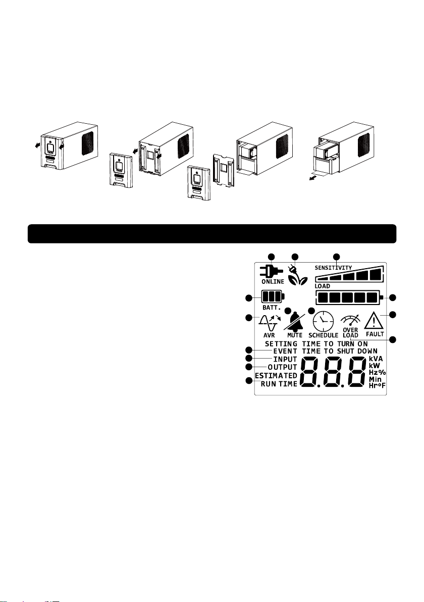
1
2
4
5
6
7
8
9
10
11
12
13
14
3
11. Conéctese a la corriente de CA y cargue las nuevas baterías durante 16 horas para garantizar la
carga completa.
RECORDATORIO: Las baterías son consideradas DESPERDICIO PELIGROSO y se debe disponer
de ellas apropiadamente.Prácticamente todos los proveedores que venden baterías de ácido de plomo
recolectan baterías usadas para reciclarlas.
DEFINICIONES PARA INDICADORES LED ILUMINADOS
1. ONLINE (En Línea): El UPS está suministrando energía
al equipo conectado.
2. BATTERY (Batería): Durante una baja de voltaje
severo o apagón, este ícono aparece y una alarma
suena (dos beeps cortos seguidos de una pausa)
para indicar que el UPS está operand en batería.
Durante una baja de voltaje severa o apagón
la alarma hará beep cada 1/2 segundo (y medidor de
CAPACIDAD DE BATERIA muestra un 20% de
capacidad del segmento sombreado. La capacidad
depende de cuánta carga tiene y del tiempo de
respaldo que queda) para indicar que las baterías del
UPS están cerca de quedarse sin energía. Deberá
guardar sus archivos y apagar su equipo
inmediatamente o permitir al software apagar el equipo.
3. Ahorro de Energía: El UPS en Modo Energy-Saving Bypass. Cuando la alimentación principal es
normal y la batería esté completamente cargada, el SAI entrará en el modo alternativo de ahorro
de energía.Vea la sección “Tecnologa GreenPower UPSTM de CyberPower” para ms informacin.
4. Capacidad de CARGA / Ajuste de Sensibilidad: Este medidor muestra el nivel de carga de
salida aproximado (en 20% de incremento) de las tomas de batería del UPS. También puede ser el
medidor de configuración de sensibilidad si se encuentra el modo de configuración. Este es para
controlar la sensibilidad del UPS para cambiar a Modo Batería con menos variación de energía de
entrada. Cuando la sensibilidad aumenta, el SAI cambia al modo de batería con menos variación
de alimentación de entrada.
5. Capacidad de BATERIA: Este medidor muestra el nivel de carga aproximado (en 20% de
incremento) de la batería interna del UPS. Durante un apagón ó baja de voltaje severa, el UPS
cambia a batería, el ícno BATTERY (Batería) aparece y el nivel de carga disminuye.
37
Page 38

6. FAULT (Falla): Este ícono aparece si hay un problema con el UPS. Presiona el botón POWER
para apagar el UPS.
F01: Battery Mode or AC/Utility Power Mode Overload fault (Falla de Sobrecarga Modo
Batería o Modo Energía CA) (Apagar el equipo no esencial. Si esto resuelve el problema de
sobrecarga, la SAI se transferirá a una operación normal.).
F02: Battery Output Short fault (Falla de Corto de Salida en Batería) (El equipo conectado
puede tener problemas; por favor, retírelos y vuelva a comprobarlo.)
F03: Charger Fault (Falla de CARGADOR) (Contacte a CyberPower Systems para soporte)
F04: Internal Fault (Falla Interna) (Contacte a CyberPower Systems para soporte)
F05: Fan Abnormal (Anomalía del ventilador) (Contact CyberPower Systems for support.)
7. OVER LOAD (Sobrecarga): Este ícono aparece y una alarma suena para indicar que la stomas
de batería están sobrecargadas. Para eliminar la sobrecarga, desconecte alguna pieza de equipo
de la stomas de batería hasta que el ícono se apague y la alarma se detenga.
8. SCHEDULE (Agenda): Los usuarios pueden ajustar la agenda para encender y apagar la
computadora y UPS mediante el programa PowerPanel® Personal Edition. El display LCD
mostrará cuánto tiempo queda antes de que el UPS regresará o se apagará.
9. ESTIMATED RUNTIME (Tiempo de Respaldo): Este muestra el tiempo de respaldo estimado del
UPS con la Capacidad de batería y carga actual.
10. OUTPUT meter (Medidor de Salida): Este mide, en tiempo real, el voltaje de CA que el UPS está
suministrando a la computadora, así como modo en línea normal CA, modo AVR y modo en
batería. (Nota: El medidor OUTPUT muestra el estatus de la stomas de batería en terminos de
carga, Frecuencia y voltaje.)
11. INPUT meter (Medidor de Entrada): Este mide el voltaje de CA que el UPS está recibiendo de la
toma del suministro de CA. El UPS está diseñado, mediante el uso de un Regulador Automático de
Voltaje, para continuamente corregir voltaje de salida al equipo conectado a un rango de voltaje
seguro de. En el caso de una pérdida de energía, baja de voltaje severa o sobrevoltaje, el UPS
recurre a su batería interna para entregar un voltaje de salida consistente de. El medidor de voltaje
de Salida puede ser usado como una herramienta diagnóstico para identificar una entrada de
energía pobre.
12. EVENT (Evento): Este medidor guarda el número de apagones.
13. MUTE (Silencio): Este ícono aparece cuando el UPS está en modo silencio. La Alarma no emitirá
beep durante el modo silencio hasta que la batería alcance una capacidad baja.
14. AVR (Regulador Automático de Voltaje) Este ícono aparece cuando su UPS esté
automáticamente corrigiendo bajo voltaje de CA sin usar la energía de la batería. Esto es una
operación normal del UPS y ninguna acción es requerida de su parte.
Para más información acerca de las funciones de ajuste, por favor refiérase a la Guía de
Ajustes de Función.
38
Page 39

ESPECIFICACIONES TÉ CNICAS
Modelo
PR2200ELCDSL
PR2200ELCDSXL
PR3000ELCDSL
PR3000ELCDSXL
Capacidad (VA)
2200VA/1980W
3000VA/2700W
Entrada
Rango de frecuencia
50/60Hz +/-3 Hz (Auto Sensing)
Función AVR
Si
Salida
Voltaje de salida con la batera
230Vac +/-10%
Frecuencia de salida con la batera
50/60Hz +/-1%
Proteccin contra sobrecargas
Con suministro eléctrico: disyuntor y protección de corriente
interna
Con batería: limitación interna de corriente
Protección contra subidas de
tensión
Protección contra rayos y subidas
de tensión
Si
Temperatura de funcionamiento
+32F to 104F ( 0C to 40C )
Fsicas
Cantidad total de tomacorrientes de
la unidad SAI
IEC x 9
Dimensiones mximas (LxWxH)
221 x 170 x 432 mm
Peso (kg)
23.3
24.5
Batera
Batera
Batería de ácido de plomo que no necesita mantenimiento
Tiempo de recarga normal
8 hours
Corriente de carga (máx.)
1A
Reemplazable por el usuario
Si
Diagnsticos de advertencia
Indicadores
Encendido, pantalla LCD, en línea,
con batería, error, cambio de batería
Alarmas sonoras
Modo con batera, Batera baja y Sobrecarga
Comunicacin
PowerPanel® Business Edition
Software
Windows 10/8/7/Vista/XP/2000/Server 2003, Linux
Administracin
Autocomprobación
Si
Autocargador
Si
Reinicio automático
Si
USB
Si
Expansion Port
Si
EPO Port
Si
Certificaciones
Certifications
CE
39
Page 40

RESOLUCIÓ N DE PROBLEMAS
Problema
Causa probable
Solucin
El botón de interruptor de
circuito sobresale en el
lateral
de la unidad.
El interruptor de
circuito
se ha disparado
debido a
una sobrecarga.
Apague el SAI y desenchufe al menos un
equipo. Espere 10 segundos, restaure el
interruptor de circuito presionando el botón
y vuelva a encender el SAI..
El SAI no se mantiene en
funcionamiento durante el
tiempo esperado.
La batería no está
cargada por completo.
Vuelva a cargar la batería manteniendo el
SAI enchufado.
La batería está
ligeramente
deteriorada.
Si desea adquirir una batería de repuesto,
póngase en contacto con CyberPower
Systems a través de la dirección de correo
electrónico.
El SAI no se enciende.
El interruptor de
encendido / apagado
ha sido diseñado para
evitar que se
produzcan daños
si se apaga y se
enciende rápidamente.
Apague el SAI. Espere 10 segundos y
vuelva a encender el SAI.
La batería está
deteriorada.
Si desea adquirir una batería de repuesto,
póngase en contacto con CyberPower
Systems a través de la dirección de correo
electrónico.
Problema mecánico.
Póngase en contacto con CyberPower
Systems a través de la dirección de correo
electrónico.
PowerPanel® Business
Edition is inactive.
El cable USB no está
conectado..
Conecte el cable USB a la unidad SAI y a
un puerto serie disponible de su PC. Debe
utilizar el cable que se incluye con la
unidad.
Si desea obtener más información acerca de cómo resolver problemas, acceda a la dirección
www.cpsww.eu
Para obtener más información, viste www.cpsww.eu o póngase en contacto con:
Cyber Power Systems, Inc.
Correo electrónico: [email protected]
Reservados todos los derechos. Prohibida la reproducción sin permiso.
40
Page 41

41
Page 42

42
 Loading...