

CyberData 011433 Operation Manual
Secure Access Control
The IP Endpoint Company
Keypad
Operations Guide
Part #011433
Document Part #931384A
for Firmware Version 1.0.0
CyberData Corporation
3 Justin Court
Monterey, CA 93940
(831) 373-2601

Secure Access Control Keypad Operations Guide 931384A
Technical Support
The fastest way to get technical support for your VoIP product is to
submit a VoIP Technical Support form at the following website:
http://support.cyberdata.net/
Phone: (831) 373-2601, Ext. 333
Email: support@cyberdata.net
Fax: (831) 373-4193
Company and product information is at www.cyberdata.net.
The IP Endpoint Company
Part # 011433
COPYRIGHT NOTICE:
© 2017, CyberData Corporation, ALL RIGHTS RESERVED.
This manual and related materials are the copyrighted property of CyberData Corporation. No part of
this manual or related materials may be reproduced or transmitted, in any form or by any means
(except for internal use by licensed customers), without prior express written permission of
CyberData Corporation. This manual, and the products, software, firmware, and/or hardware
described in this manual are the property of CyberData Corporation, provided under the terms of an
agreement between CyberData Corporation and recipient of this manual, and their use is subject to
that agreement and its terms.
DISCLAIMER: Except as expressly and specifically stated in a written agreement executed by
CyberData Corporation, CyberData Corporation makes no representation or warranty, express or
implied, including any warranty or merchantability or fitness for any purpose, with respect to this
manual or the products, software, firmware, and/or hardware described herein, and CyberData
Corporation assumes no liability for damages or claims resulting from any use of this manual or such
products, software, firmware, and/or hardware. CyberData Corporation reserves the right to make
changes, without notice, to this manual and to any such product, software, firmware, and/or
hardware.
OPEN SOURCE STATEMENT: Certain software components included in CyberData products are
subject to the GNU General Public License (GPL) and Lesser GNU General Public License (LGPL)
“open source” or “free software” licenses. Some of this Open Source Software may be owned by third
parties. Open Source Software is not subject to the terms and conditions of the CyberData
COPYRIGHT NOTICE or software licenses. Your right to copy, modify, and distribute any Open
Source Software is determined by the terms of the GPL, LGPL, or third party, according to who
licenses that software.
CyberData Corporation 931384A Operations Guide
Software or firmware developed by CyberData that is unrelated to Open Source Software is
copyrighted by CyberData, subject to the terms of CyberData licenses, and may not be copied,
modified, reverse-engineered, or otherwise altered without explicit written permission from
CyberData Corporation.
TRADEMARK NOTICE: CyberData Corporation and the CyberData Corporation logos are
trademarks of CyberData Corporation. Other product names, trademarks, and service marks may be
the trademarks or registered trademarks of their respective owners.

Revision Information
Revision 931384A, which corresponds to firmware version 1.0.0, was released on September 19,
2017.
Browsers Supported
The following browsers have been tested against firmware version 1.0.0:
• Chrome (version 570.02987.98)
• Firefox: (version 55.0.2)
• Internet Explorer (version 11.0.9600.18314)
Operations Guide 931384A CyberData Corporation
Pictorial Alert Icons
GENERAL ALERT
Hazard Levels
Danger: Indicates an imminently hazardous situation which, if not avoided, will result in death or
serious injury. This is limited to the most extreme situations.
Warning: Indicates a potentially hazardous situation which, if not avoided, could result in death or
serious injury.
General Alert
This pictoral alert indicates a potentially hazardous situation. This alert will be
followed by a hazard level heading and more specific information about the hazard.
Ground
This pictoral alert indicates the Earth grounding connection point.
Caution: Indicates a potentially hazardous situation which, if not avoided, could result in minor or
moderate injury. It may also alert users against unsafe practices.
Notice: Indicates a statement of company policy (that is, a safety policy or protection of property).
The safety guidelines for the equipment in this manual do not purport to address all the safety issues
of the equipment. It is the responsibility of the user to establish appropriate safety, ergonomic, and
health practices and determine the applicability of regulatory limitations prior to use. Potential safety
hazards are identified in this manual through the use of words Danger, Warning, and Caution, the
specific hazard type, and pictorial alert icons.
CyberData Corporation 931384A Operations Guide
Important Safety Instructions
GENERAL ALERT
GENERAL ALERT
GENERAL ALERT
1. Read these instructions.
2. Keep these instructions.
3. Heed all warnings.
4. Follow all instructions.
5. Do not use this apparatus near water.
6. Clean only with dry cloth.
7. Do not block any ventilation openings. Install in accordance with the manufacturer’s instructions.
8. Do not install near any heat sources such as radiators, heat registers, stoves, or other apparatus
(including amplifiers) that produce heat.
9. Do not defeat the safety purpose of the polarized or grounding-type plug. A polarized plug has
two blades with one wider than the other. A grounding type plug has two blades and a third
grounding prong. The wide blade or the third prong are provided for your safety. If the provided
plug does not fit into your outlet, consult an electrician for replacement of the obsolete outlet.
10. Protect the power cord from being walked on or pinched particularly at plugs, convenience
receptacles, and the point where they exit from the apparatus.
11. Only use attachments/accessories specified by the manufacturer.
12. Refer all servicing to qualified service personnel. Servicing is required when the apparatus has
been damaged in any way, such as power-supply cord or plug is damaged, liquid has been
spilled or objects have fallen into the apparatus, the apparatus has been exposed to rain or
moisture, does not operate normally, or has been dropped.
13. Prior to installation, consult local building and electrical code requirements.
14. WARNING: The Intercom enclosure is not rated for any AC voltages!
Warn in g
Electrical Hazard: This product should be installed by a licensed electrician
according to all local electrical and building codes.
Warn in g
Electrical Hazard: To prevent injury, this apparatus must be securely attached to
the floor/wall in accordance with the installation instructions.
Warn in g
The PoE connector is intended for intra-building connections only and does not
route to the outside plant.
CyberData Corporation 931384A Operations Guide

Contents
Chapter 1 Product Overview 1
1.1 How to Identify This Product .....................................................................................................1
1.2 Typical System Installation .......................................................................................................2
1.3 Product Features ......................................................................................................................4
1.4 Supported Protocols .................................................................................................................5
1.5 Supported SIP Servers .............................................................................................................5
1.6 Specifications ...........................................................................................................................6
Chapter 2 Installing the Secure Access Control Keypad 7
2.1 Parts List ..................................................................................................................................7
2.2 Intercom Components ..............................................................................................................8
2.3 Secure Access Control Keypad Setup ......................................................................................9
2.4 Configure the Intercom Parameters .......................................................................................19
2.5 Upgrade the Firmware and Reboot the Intercom ...................................................................72
2.6 Command Interface ................................................................................................................76
i
2.3.1 Intercom Connections ....................................................................................................9
2.3.2 Using the On-Board Relay ...........................................................................................10
2.3.3 Wiring the Circuit ..........................................................................................................11
2.3.4 Connectors and Functions ...........................................................................................15
2.3.5 Activity and Link LEDs .................................................................................................17
2.3.6 Restoring the Factory Default Settings .........................................................................18
2.4.1 Factory Default Settings ...............................................................................................19
2.4.2 Intercom Web Page Navigation ....................................................................................20
2.4.3 Using the Toggle Help Button .......................................................................................21
2.4.4 Log in to the Configuration Home Page .......................................................................23
2.4.5 Configure the Device ....................................................................................................27
2.4.6 Configure the Security ..................................................................................................33
2.4.7 Configure the Network Parameters .............................................................................40
2.4.8 Configure the SIP (Session Initiation Protocol) Parameters .........................................43
2.4.9 Configure the Sensor Configuration Parameters ..........................................................47
2.4.10 Configure the Audio Configuration Parameters ..........................................................50
2.4.11 Configure the Events Parameters ..............................................................................53
2.4.12 Configure the Door Strike Relay .................................................................................58
2.4.13 Configure the Autoprovisioning Parameters ...............................................................60
2.5.1 Downloading the Firmware ...........................................................................................72
2.5.2 Reboot the Device ........................................................................................................75
2.6.1 Command Interface Post Commands ..........................................................................76
Appendix A Mounting the Intercom 77
A.1 Mounting Components ...........................................................................................................77
A.2 Dimensions ............................................................................................................................78
A.3 Overview of Installation Types ................................................................................................80
A.4 Service Loop Cable Routing ..................................................................................................81
A.5 Securing the Enclosure ..........................................................................................................82
A.6 Additional Mounting Options ..................................................................................................83
A.6.1 Conduit Mounting (Side Entry) (Not Provided) ............................................................83
A.6.2 Goose Neck Mounting Option (Not Provided) ..............................................................84
Appendix B Setting up a TFTP Server 85
B.1 Set up a TFTP Server ............................................................................................................85
B.1.1 In a LINUX Environment ..............................................................................................85
B.1.2 In a Windows Environment .........................................................................................85
Appendix C Troubleshooting/Technical Support 86
C.1 Frequently Asked Questions (FAQ) ........................................................................................86
C.2 Documentation .......................................................................................................................86
C.3 Contact Information ................................................................................................................87
C.4 Warranty and RMA Information ..............................................................................................87
Operations Guide 931384A CyberData Corporation

Index 88
ii
Operations Guide 931384A CyberData Corporation
1 Product Overview
Secure Access Control Keypad
011433A / 021106Q
www.cyberdata.net
V1.0.0
00:20:F7:03:83:CA
433100001
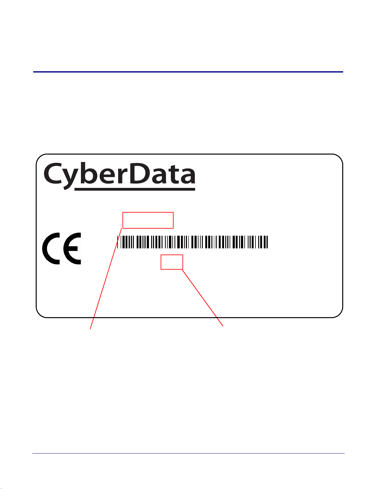
Model number
Serial number begins with 433
This device complies with part 15 of the FCC Rules. Operation is subject to the following two conditions: (1)
This device may not cause harmful interference, and (2) this device must accept any interference received,
including interference that may cause undesired operation.
CAN ICES-3 (A)/NMB-3(A)
00:20:F7:03:83:CA
1.1 How to Identify This Product
To identify the Secure Access Control Keypad, look for a model number label similar to the one
shown in
Figure 1-1. Confirm the following:
• The model number on the label should be 011433.
• The serial number on the label should begin with 433.
Figure 1-1. Model Number Label
1
Operations Guide 931384A CyberData Corporation
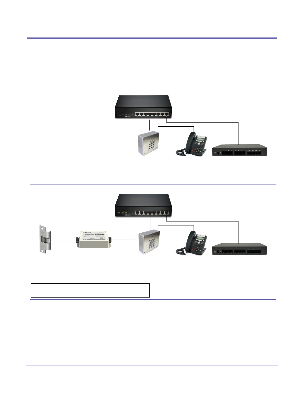
1.2 Typical System Installation
802.3af Compliant Ethernet Switch
IP Phone IP PBX Server
Endpoint
802.3af Compliant Ethernet Switch
IP Phone IP PBX ServerDoor Strike
011269 Door Strike Relay
Module (sold separately)*
*See the Quick-Reference Placemat or Operations Guide
of the relevant door strike relay for connection specifics.
Endpoint
The following figures illustrate how the Secure Access Control Keypad can be installed as part of a
VoIP phone system.
Figure 1-2. Typical Installation
Product Overview
Typical System Installation
2
Figure 1-3. Installation with the Door Strike Relay Module
Operations Guide 931384A CyberData Corporation
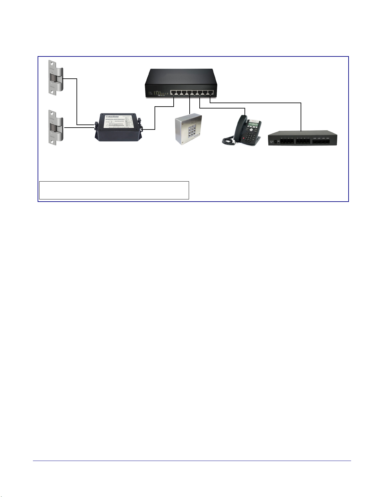
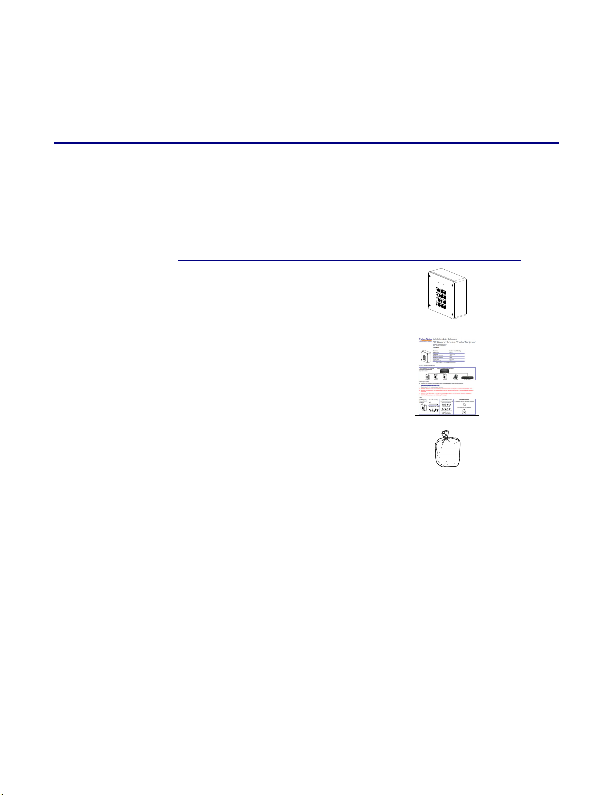
Figure 1-4. Installation with the Network Dual Door Strike Relay
802.3at Compliant Ethernet Switch
IP Phone IP PBX ServerDoor Strike
011375 Network Dual
Door Strike Relay
(sold separately)*
*See the Quick-Reference Placemat or Operations Guide
of the relevant door strike relay for connection specifics.
Door Strike
Endpoint
Product Overview
Typical System Installation
3
Operations Guide 931384A CyberData Corporation

1.3 Product Features
The SIP Outdoor Intercom has the following features:
• SIP compliant
• PoE 802.3af enabled (Powered-over-Ethernet)
• IP 65 outdoor-rated
• Optional weather shroud for even greater weather protection
•Alert buzzer
• Red/Green lock status lights
• Can operate in standalone mode. PBX not required. Future-proof and adaptable when
upgrading to new VoIP PBX
• Built in time of access scheduler
• Local and remote logging with time stamp
• NTP time support
• Network web management
• Supports 500 Access Codes
• Blacklisted code alert via dialout and multicast stored message
• Network downloadable firmware
• Dry contact relay to trigger door lock or unlock gates
• Door closure and tamper alert signal
• Support for CyberData’s Networked Dual Door Strike Relay (part# 011375) and Intermediate
Door Strike Relay (part# 011269)
• Security Torx screws with driver kit included
Product Overview
Product Features
4
Operations Guide 931384A CyberData Corporation

1.4 Supported Protocols
The Intercom supports the following protocols:
• SIP (session initiation protocol)
• HTTP Web-based configuration
Provides an intuitive user interface for easy system configuration and verification of Intercom
operations.
• DHCP Client
Dynamically assigns IP addresses in addition to the option to use static addressing.
• TFTP Client
Facilitates hosting for the Autoprovisioning configuration file.
•RTP
• Facilitates autoprovisioning configuration values on boot
• Audio Encodings
PCMU (G.711 mu-law)
PCMA (G.711 A-law)
G.722
Packet Time 20 ms
Product Overview
Supported Protocols
5
1.5 Supported SIP Servers
The following link contains information on how to configure the device for the supported SIP servers:
http://www.cyberdata.net/connecting-to-ip-pbx-servers/
Operations Guide 931384A CyberData Corporation

Product Overview
Specifications
1.6
Specifications
Table 1-1. Specifications
Specifications
Ethernet I/F 10/100 Mbps
Protocol SIP RFC 3261 Compatible
Power Input PoE 802.3af compliant or +8 to +12VDC @ 1000mA Regulated Power Supply
On-Board Relay 1A at 30 VDC
Operating Range Temperature: -40
Humidity: 5-95%, non-condensing
Storage Temperature
Storage Altitude
IP Rating IP65
Payload Types G711, A-law and µ-law, G.722
Dimensions
Weight
Boxed Weight
Compliance CE; EMC Directive – Class A EN 55032 & EN 55024, LV Safety Directive – EN 60950-1, RoHS
Part Number 011433
b
o
-40
C to 70o C (-40o F to 158o F)
Up to 15,000 ft. (4573 m)
5.118 inches [130 mm] Length
2.172 inches [55.2 mm] Width
5.118 inches [130 mm] Height
2.0 lbs. (0.90 kg)
3.0 lbs. (1.36 kg)
pliant, FCC; Part 15 Class A, Industry Canada; ICES-3 Class A, IEEE 802.3 Compliant
Com
011188 Weather Shroud (sold separately)
o
C to 55o C (-40o F to 131o F)
a
6
a. Contacts 1 and 2 on the J3 terminal block are only for powering the device from a non-PoE 12VDC power source
as an alternative to Network PoE power. Use of these contacts for any other purpose will damage the device and void
the product warranty.
b. Dimensions are measured from the perspective of the product being upright with the front of the product facing you.
Operations Guide 931384A CyberData Corporation
2 Installing the Secure Access Control Keypad
2.1 Parts List
Ta bl e 2-1 illustrates the SIP Outdoor Intercom parts.
Note See Appendix A, "Mounting the Intercom" for physical mounting information.
Table 2-1. Parts List
Quantity Part Name Illustration
1 Intercom Assembly
7
1 Installation Quick Reference Guide
1 Intercom Mounting Accessory Kit
Operations Guide 931384A CyberData Corporation
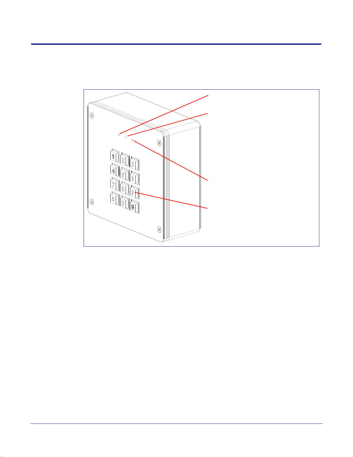
2.2 Intercom Components
Green LED
Keypad
Buzzer
The buzzer LED:
• Remains RED when the door is locked.
• Flashes GREEN when a valid code is entered.
• Flashes RED when an invalid or blacklisted
code is entered.
See Buzzer Settings in Table 2-12, "Security
Configuration Parameters".
Red LED
Figure 2-1 shows the components of the Intercom.
Figure 2-1. Intercom Components
Installing the Secure Access Control Keypad
Intercom Components
8
Operations Guide 931384A CyberData Corporation
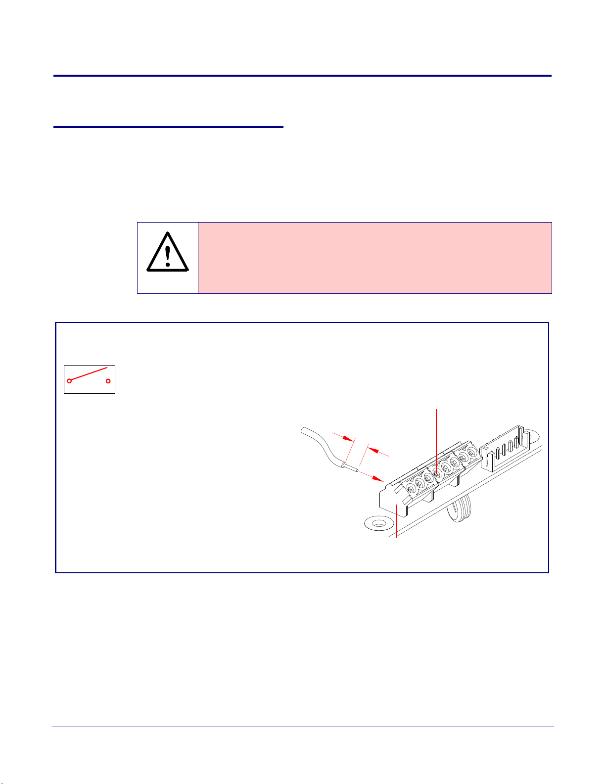
Installing the Secure Access Control Keypad
GENERAL ALERT
0.25"
Terminal Block
Wire (IN)
can accept 16 AWG wire
1
8
Alternate Power Input:
1 = +8 to +12VDC @ 1000mA Regulated Power Supply*
2 = Power Ground*
Relay Contact:
(1 A at 30 VDC for continuous loads)
3 = Relay Common
4 = Relay Normally Open Contact
5 = Sense Input
6 = Sense Ground
7 = Remote Switch "A"
8 = Remote Switch "B"
*Contacts 1 and 2 on the terminal block are only for
powering the device from a non-PoE 12VDC power
source as an alternative to Network PoE power. Use of
these contacts for any other purpose will damage the
device and void the product warranty.
3
4
Use a 3.17 mm (1/8-inch) flat blade
screwdriver for the terminal block screws
2.3 Secure Access Control Keypad Setup
2.3.1 Intercom Connections
Figure 2-2 shows the pin connections on the terminal block. This terminal block can accept
16 AWG gauge wire.
Secure Access Control Keypad Setup
9
Note As an alternative to
Power Supply into the terminal block.
Caution
Equipment Hazard: Contacts 1 and 2 on the terminal block are only for powering
the device from a non-PoE 12 VDC power source as an alternative to Network PoE
power. Use of these contacts for any other purpose will damage the device and void
the product warranty.
Figure 2-2. Connections and Alternate Power Input
using PoE power, you can supply +8 to +12VDC @ 1000mA Regulated
Operations Guide 931384A CyberData Corporation
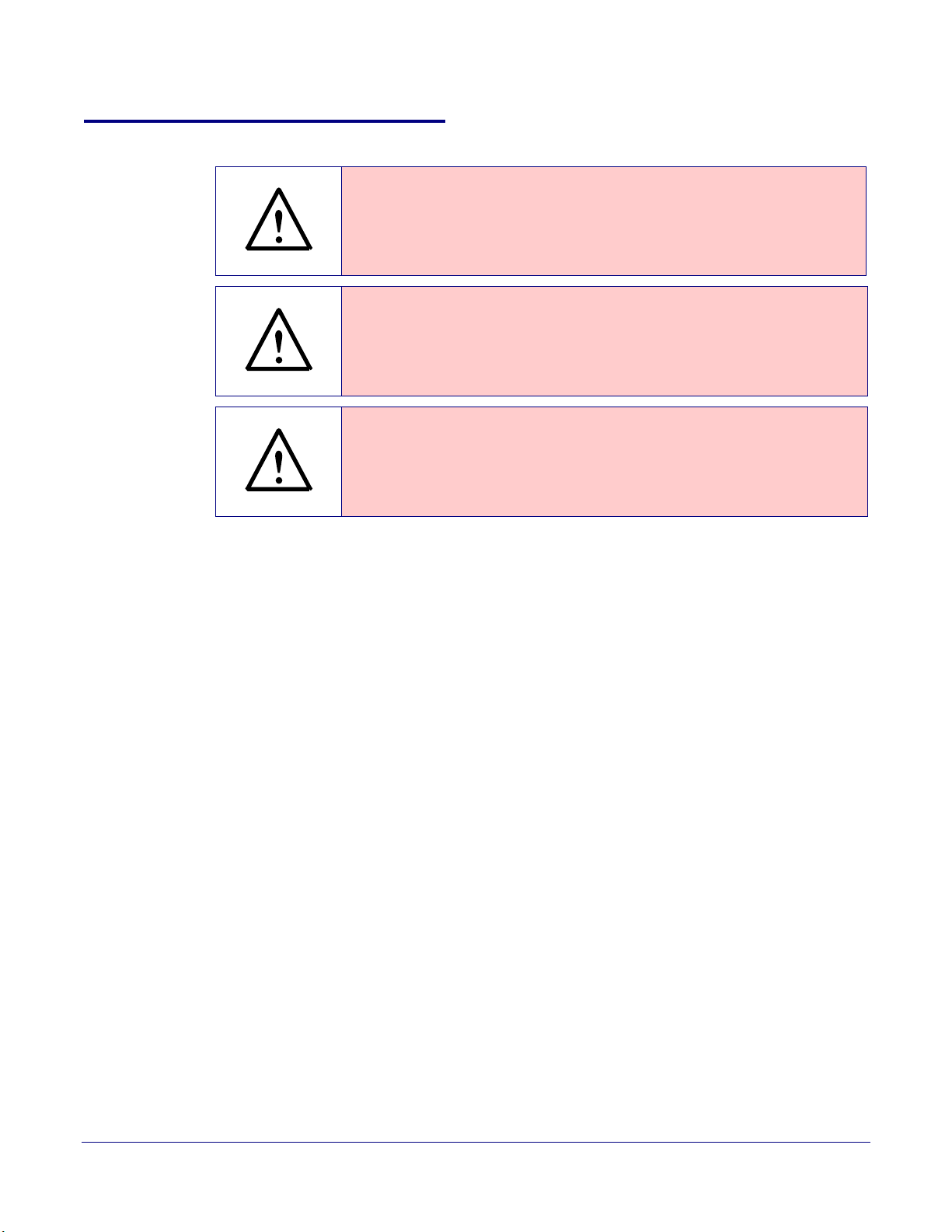
2.3.2 Using the On-Board Relay
GENERAL ALERT
GENERAL ALERT
GENERAL ALERT
Warning
Electrical Hazard:
according to all local electrical and building codes.
Warning
Electrical Hazard:
and momentarily closed configuration. Neither the alternate power input nor PoE
power can be used to drive a door strike.
Warning
Electrical Hazard:
Any use of this relay beyond its normal operating range can cause damage to the
product and is not covered under our warranty policy.
Installing the Secure Access Control Keypad
Secure Access Control Keypad Setup
This product should be installed by a licensed electrician
The relay contacts are dry and provided for a normally open
The relay does not support AC powered door strikes.
10
The device has a built-in relay that can be activated by a web configurable DTMF string that can be
received from a VoIP phone supporting out of band (RFC2833) DTMF as well as a number of other
triggering events. See the Device Configuration Page on the web interface for relay settings.
This relay can be used to trigger low current devices like LED strobes and security camera input
signals as long as the load is not an indu
1 Amp @ 30 VDC. Inductive loads can cause excess
ctive type and the relay is limited to a maximum of
ive “hum” and can interfere with or damage the
unit’s electronics.
We highly recommend that inductive load and high current de
vices use our Networked Dual Door
Strike Relay (CD# 011375) (see Section 2.3.3.2, "Network Dual Door Strike Relay Wiring Diagram
with External Power Source").
This relay interface also has a general purpose input port that can be used to monitor an external
s
witch and generate an event.
For more information on the sensor options, see the Sensor Configuration Page on the web
interface.
Operations Guide 931384A CyberData Corporation
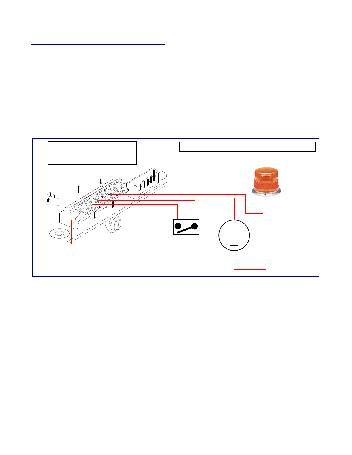
2.3.3 Wiring the Circuit
DC Source
+
1 A @ 30 VDC
Sense Input
LED Strobe Light
Terminal Block of the CyberData Device
1
8
The terminal block can accept 16 AWG stranded wire.
Pin 3 - Relay Common
Pin 4 - Relay Normally Open Contact
Pin 5 - Sense Input
Pin 6 - Sense Ground
2.3.3.1 Devices Less than 1A at 30 VDC
If the power for the device is less than 1A at 30 VDC and is not an inductive load, then see
Figure 2-3 for the wiring diagram.
When configuring with an inductive load, please use an intermediary relay with a High PIV Ultrafast
Switching Diode. We recommend using the Network Dual Door Strike Relay (CD# 011375) (see
Section 2.3.3.2, "Network Dual Door Strike Relay Wiring Diagram with External Power Source").
Figure 2-3. Devices Less than 1A at 30 VDC
Installing the Secure Access Control Keypad
Secure Access Control Keypad Setup
11
Operations Guide 931384A CyberData Corporation

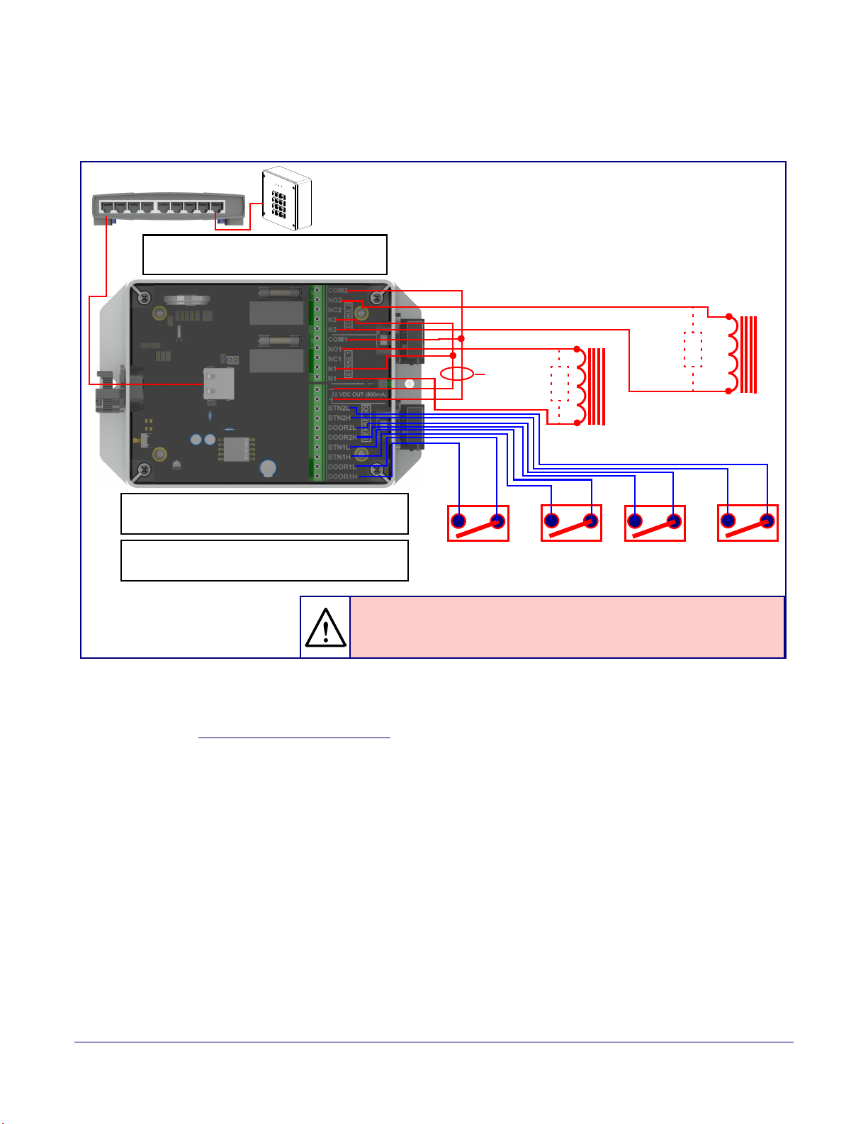
Installing the Secure Access Control Keypad
GENERAL ALERT
Sense Input 2
DC Source 2
AC Source 2
OR
+
802.3af Compliant Ethernet Switch
CyberData
Aux Button 2
Device
The relay connection maximum wire
size is 12 gauge stranded wire.
Door Strike
Sense Input 1
DC Source 1
AC Source 1
OR
+
Aux Button1
*
Door Strike
*
GENERAL ALERT
*Caution
Equipment Hazard: The door strike must have an internal or external mov or
diode (for over voltage protection) when connecting directly to the module.
See the Network Dual Door Strike Relay
Operations Guide for connection specifics.
See Section 2.4.12, "Configure the Door Strike
Relay" for configuration options.
Secure Access Control Keypad Setup
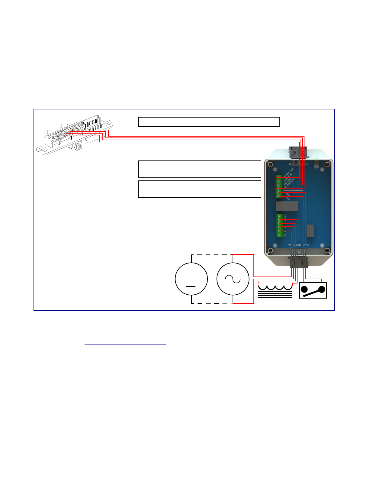
2.3.3.2 Network Dual Door Strike Relay Wiring Diagram with External Power Source
For wiring an electronic door strike to work over a network, we recommend the use of our external
Network Dual Door Strike Relay (CD# 011375).
This product provides an easier method of connecting standard door strikes as well as AC and
h
igher voltage devices. See Figure 2-4 and Figure 2-5 for the wiring diagrams.
Warn in g
Electrical Hazard:
part inside. Refer to qualified service personnel for connecting or servicing.
Figure 2-4. Network Dual Door Strike Relay Wiring Diagram with External Power Source
Hazardous voltages may be present. No user serviceable
12
Operations Guide 931384A CyberData Corporation
Installing the Secure Access Control Keypad
Sense Input 2 Aux Button 2Sense Input 1 Aux Button1
Door Strike
*
Door Strike
*
802.3at Compliant Ethernet Switch
The relay connection maximum wire size
is 12 gauge stranded wire.
Internal 12VDC
source (500 mA
maximum)
GENERAL ALERT
*Caution
Equipment Hazard: The door strike must have an internal or external mov or
diode (for over voltage protection) when connecting directly to the module.
See the Network Dual Door Strike Relay
Operations Guide for connection specifics.
See Section 2.4.12, "Configure the Door Strike
Relay" for configuration options.
CyberData
Device
Secure Access Control Keypad Setup
2.3.3.3 Network Dual Door Strike Relay Wiring Diagram Using 802.3at
Figure 2-5. Network Dual Door Strike Relay Wiring Diagram Using 802.3at
13
If you have questions about connecting door strikes or setting up the web configurable options,
please contact our support department at the following website:
http://support.cyberdata.net/
Operations Guide 931384A CyberData Corporation
Installing the Secure Access Control Keypad
Door Lock Sense Input
The terminal block can accept 16 AWG stranded wire.
DC Source
AC Source
OR
+
1
8
Terminal Block
See the Door Strike Relay Module Operations
Guide for connection specifics.
See Section 2.4.12, "Configure the Door Strike
Relay" for configuration options.
Secure Access Control Keypad Setup
2.3.3.4 Door Strike Relay Module Wiring Diagram from the Device
For wiring an electronic door strike, we recommend the use of our external Door Strike Relay Module
(CD# 011269).
This product provides an easier method of connecting standard door strikes as well as AC and
higher voltage devices. See
Figure 2-6. Door Strike Relay Module Wiring Diagram from the Device
Figure 2-6 for the wiring diagram.
14
If you have questions about connecting door strikes or setting up the web configurable options,
please contact our support department at the following website:
http://support.cyberdata.net/
Operations Guide 931384A CyberData Corporation

2.3.4 Connectors and Functions
See the following figures and tables to identify the connectors and functions.
Installing the Secure Access Control Keypad
Secure Access Control Keypad Setup
Figure 2-7. Connector Locations
15
Table 2-2. Connector Functions
Connector Function
J2 Call Button LED Interface
J6 Microphone Interface
J7 Speaker Interface
J8 Keypad Interface (Not Used)
J9A I²C 5V Peripheral Bus
JP10 Disables the intrusion sensor when installed.
Operations Guide 931384A CyberData Corporation
Installing the Secure Access Control Keypad
Secure Access Control Keypad Setup
Figure 2-8. Connector Locations
16
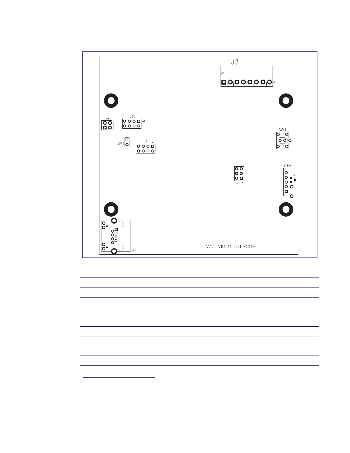
Table 2-3. Connector Functions
Connector Function
J1 PoE Network Connection (RJ-45 ethernet)
J3 Terminal Block (see Figure 2-2)
J4 Console Port (Factory Use Only)
JP1 Reset Jumper
a
J12 Reserved (Factory Use Only)
J5 JTAG (Factory Use Only)
J9B Buzzer/LED Board Interface
SW1 See Section 2.3.6, "Restoring the Factory Default Settings"
Q8 Intrusion Sensor
a.Do not install a jumper. Momentary short to reset. Permanent installation of a jumper would
prevent the board from running all together.
Operations Guide 931384A CyberData Corporation
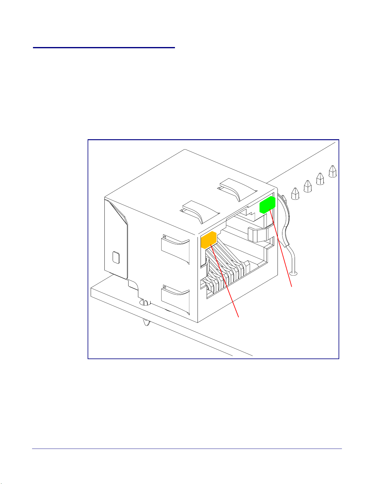
2.3.5 Activity and Link LEDs
Link
Activity
2.3.5.1 Verifying the Network Connectivity and Data Rate
When you plug in the Ethernet cable or power supply to the device, the following occurs:
• The square, AMBER Link/Activity LED blinks when there is network activity (see Figure 2-9).
• The square, GREEN 100Mb Link LED above the Ethernet port indicates that the network
connection has been established (see
Figure 2-9. Activity and Link LED
Figure 2-9).
Installing the Secure Access Control Keypad
Secure Access Control Keypad Setup
17
Operations Guide 931384A CyberData Corporation
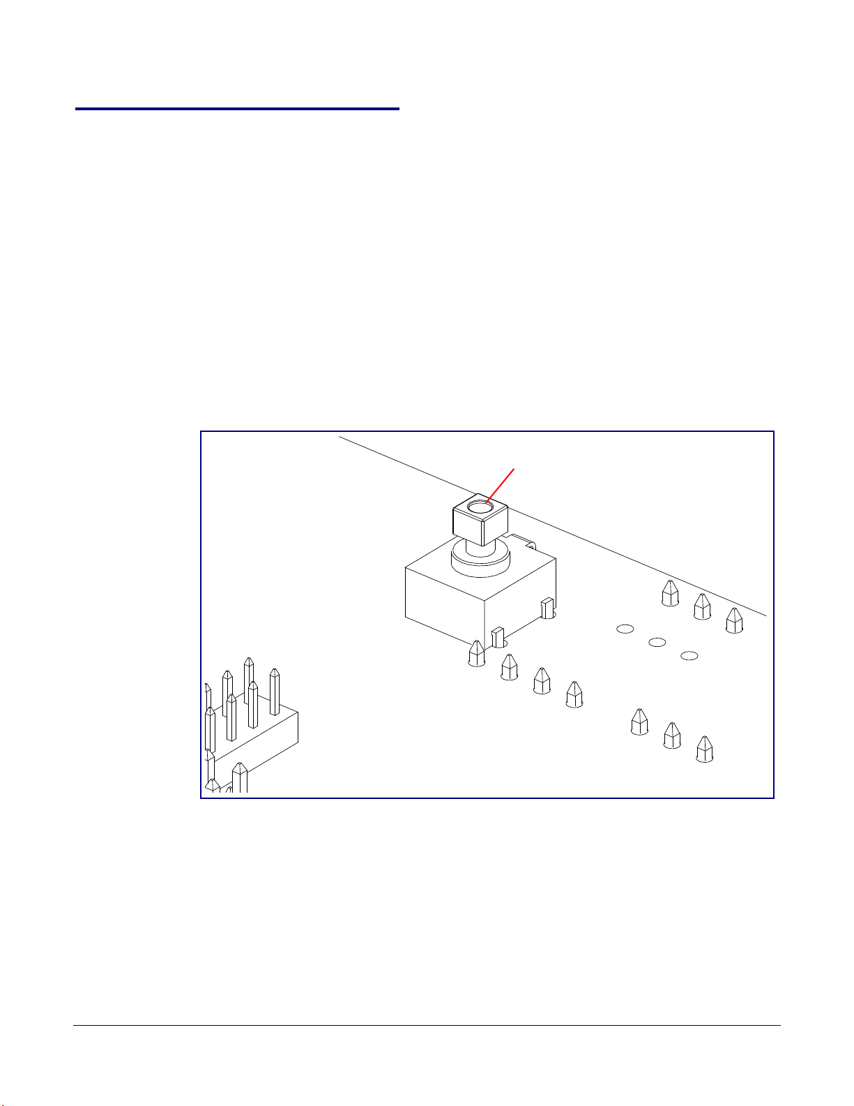
2.3.6 Restoring the Factory Default Settings
RTFM button (SW1)
When troubleshooting configuration problems, it is sometimes convenient to restore the device to a
known state.
Note Each device is delivered with factory set default values.
To restore the factory default settings:
1. Press and hold the RTFM button (see SW1 in Figure 2-10) for more than five seconds.
2. When the RTFM button is pressed, the keypad lights turn off (if the brightness is not set to 0).
3. The keypad lights blink during the boot process, turn off briefly, and then remain on and solid.
Note THE device will use DHCP to obtain the new IP address (DHCP-assigned address or default
to 10.10.10.10 if a DHCP server is not present).
Figure 2-10. RTFM Button
Installing the Secure Access Control Keypad
Secure Access Control Keypad Setup
18
Operations Guide 931384A CyberData Corporation

Installing the Secure Access Control Keypad
2.4 Configure the Intercom Parameters
To configure the Intercom online, use a standard web browser.
Secure Access Control Keypad Setup
19
Configure each Intercom and verify its operation bef
an Intercom, refer to Appendix A, "Mounting the Intercom" for instructions.
2.4.1 Factory Default Settings
All Intercoms are initially configured with the following default IP settings:
When configuring more than one Intercom, attach the Intercoms to the network and configure one at
a
time to avoid IP address conflicts.
Parameter Factory Default Setting
IP Addressing DHCP
IP Address
Web Access Username admin
Web Access Password admin
Subnet Mask
Default Gateway
ore you mount it. When you are ready to mount
Table 2-4. Factory Default Settings
a
a
a
10.10.10.10
255.0.0.0
10.0.0.1
a. Default if there is not a DHCP server present.
Operations Guide 931384A CyberData Corporation
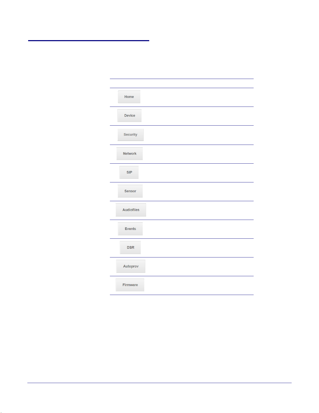
2.4.2 Intercom Web Page Navigation
Ta bl e 2-5 shows the navigation buttons that you will see on every Intercom web page.
Table 2-5. Web Page Navigation
Web Page Item Description
Installing the Secure Access Control Keypad
Link to the Home page.
Link to the Device page.
Secure Access Control Keypad Setup
20
Link to the Security page
Link to the Netw
Link to go to the SIP pag
Link to the Sensor page.
Link to the Audiofiles page.
Link to the Events page.
Link to the Door Strike Relay page.
Link to the A
Link to the Firmware page.
ork page.
utoprovisioning page.
.
e.
Operations Guide 931384A CyberData Corporation
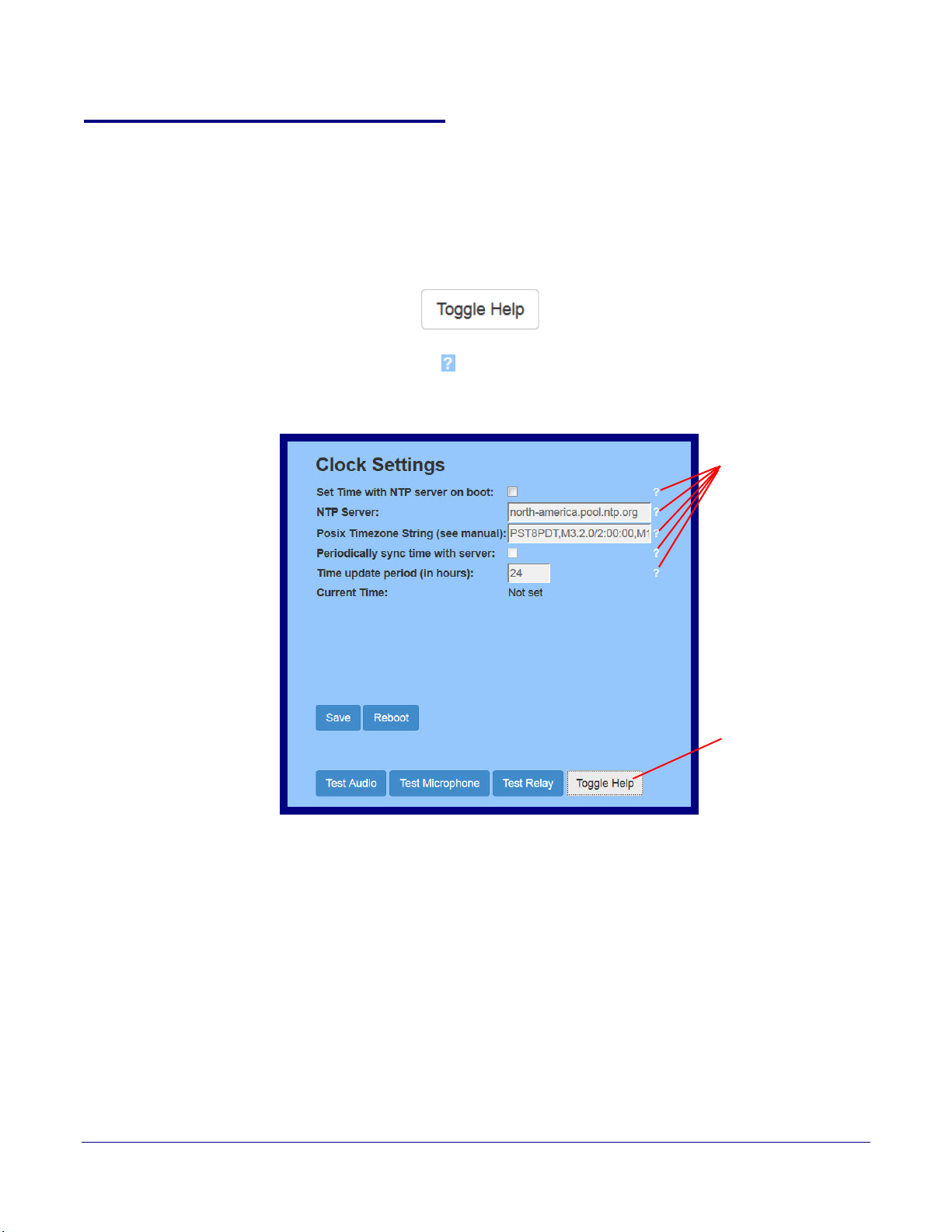
2.4.3 Using the Toggle Help Button
Toggle Help button
Question mark
appears next to the
web page items
The Toggle Help button allows you to see a short description of some of the settings on the
webpage. To use the Toggle Help button, do the following:
Installing the Secure Access Control Keypad
Secure Access Control Keypad Setup
21
1. Click on the T
oggle Help button that is on the UI webpage. See Figure 2-11 and Figure 2-12.
Figure 2-11. Toggle/Help Button
2. You will see a question mark (
) appear next to each web page item that has been provided
with a short description by the Help feature. See Figure 2-12.
Figure 2-12. Toggle Help Button and Question Marks
Operations Guide 931384A CyberData Corporation
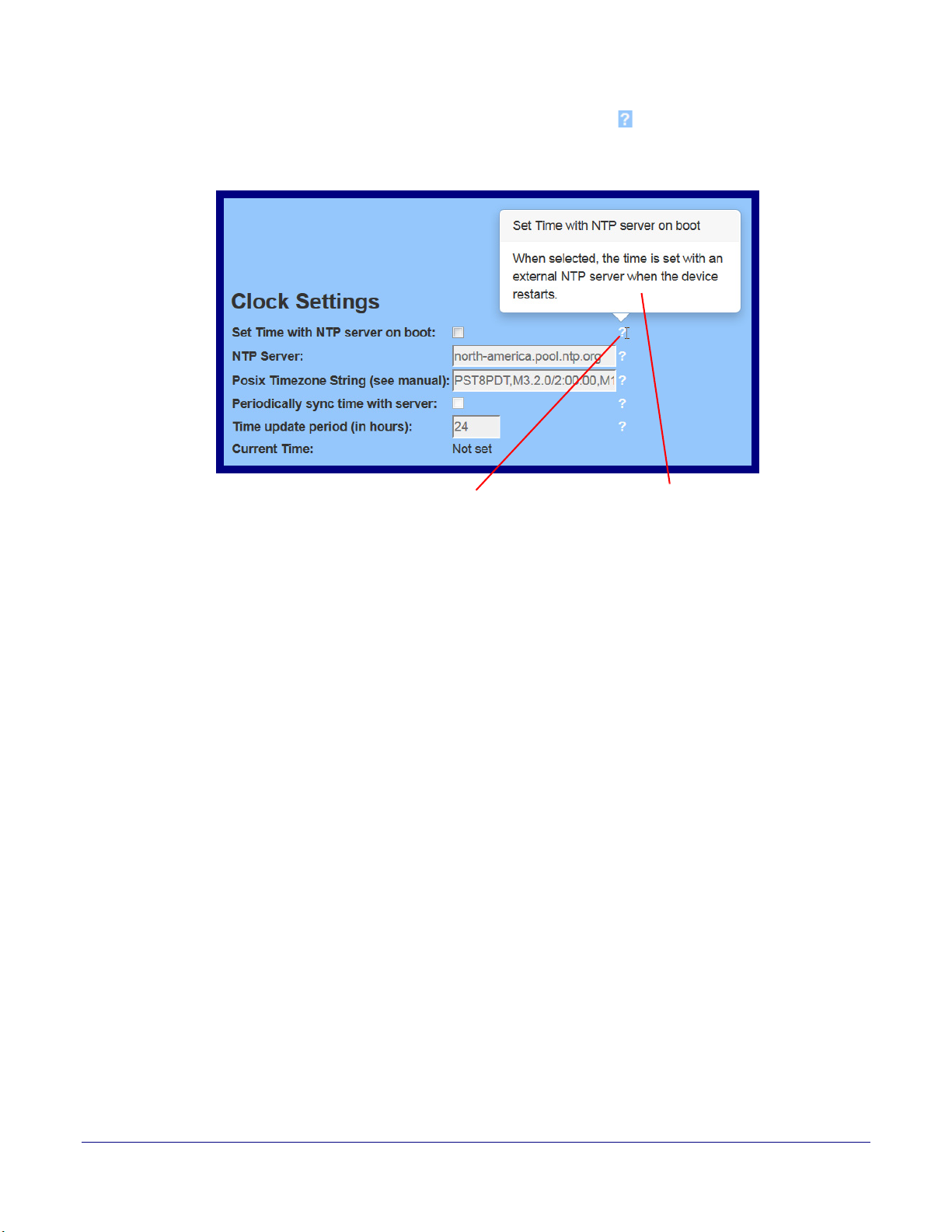
Installing the Secure Access Control Keypad
A short description of the
web page item will appear
Question mark
Secure Access Control Keypad Setup
3. Move the mouse pointer to hover over the question mark ( ), and a short description of the web
page item will appear. See Figure 2-13.
Figure 2-13. Short Description Provided by the Help Feature
22
Operations Guide 931384A CyberData Corporation

2.4.4 Log in to the Configuration Home Page
1. Open your browser to the Intercom IP address.
Note If the network does not have access to a DHCP server, the device will default to an IP
address of 10.10.10.10.
Note Make sure that the PC is on the same IP network as the Intercom.
Note You may also download CyberData’s VoIP Discovery Utility program which allows you to
easily find and configure the default web address of the CyberData VoIP products.
CyberData’s VoIP Discovery Utility program is available at the following website address:
http://www.cyberdata.net/assets/common/discovery.zip
Note The device ships in DHCP mode. To get to the Home page, use the discovery utility to scan
for the device on the network and open your browser from there.
2. When prompted, use the following default Web Access Username and Web Access
Password to access the Home Page (
Web Access Username: admin
Web Access Password: admin
Figure 2-14):
Installing the Secure Access Control Keypad
Secure Access Control Keypad Setup
23
Operations Guide 931384A CyberData Corporation
 Loading...