

Page 1
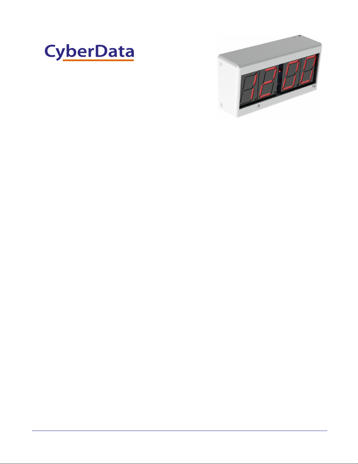
PoE Digital Clock
The IP Endpoint Company
Operations Guide
Part #011313
Document Part #931080C
for Firmware Version 1.2.3.31
CyberData Corporation
3 Justin Court
Monterey, CA 93940
(831) 373-2601
Page 2

PoE Digital Clock Operations Guide 931080C
Technical Support
The fastest way to get technical support for your VoIP product is to
submit a VoIP Technical Support form at the following website:
http://support.cyberdata.net/
Phone: (831) 373-2601, Ext. 333
Email: [email protected]
Fax: (831) 373-4193
Company and product information is at www.cyberdata.net.
The IP Endpoint Company
01 Part #011313
COPYRIGHT NOTICE:
© 2017, CyberData Corporation, ALL RIGHTS RESERVED.
This manual and related materials are the copyrighted property of CyberData Corporation. No part of
this manual or related materials may be reproduced or transmitted, in any form or by any means
(except for internal use by licensed customers), without prior express written permission of
CyberData Corporation. This manual, and the products, software, firmware, and/or hardware
described in this manual are the property of CyberData Corporation, provided under the terms of an
agreement between CyberData Corporation and recipient of this manual, and their use is subject to
that agreement and its terms.
DISCLAIMER: Except as expressly and specifically stated in a written agreement executed by
CyberData Corporation, CyberData Corporation makes no representation or warranty, express or
implied, including any warranty or merchantability or fitness for any purpose, with respect to this
manual or the products, software, firmware, and/or hardware described herein, and CyberData
Corporation assumes no liability for damages or claims resulting from any use of this manual or such
products, software, firmware, and/or hardware. CyberData Corporation reserves the right to make
changes, without notice, to this manual and to any such product, software, firmware, and/or
hardware.
OPEN SOURCE STATEMENT: Certain software components included in CyberData products are
subject to the GNU General Public License (GPL) and Lesser GNU General Public License (LGPL)
“open source” or “free software” licenses. Some of this Open Source Software may be owned by third
parties. Open Source Software is not subject to the terms and conditions of the CyberData
COPYRIGHT NOTICE or software licenses. Your right to copy, modify, and distribute any Open
Source Software is determined by the terms of the GPL, LGPL, or third party, according to who
licenses that software.
CyberData Corporation 931080C Operations Guide
Software or firmware developed by CyberData that is unrelated to Open Source Software is
copyrighted by CyberData, subject to the terms of CyberData licenses, and may not be copied,
modified, reverse-engineered, or otherwise altered without explicit written permission from
CyberData Corporation.
TRADEMARK NOTICE: CyberData Corporation and the CyberData Corporation logos are
trademarks of CyberData Corporation. Other product names, trademarks, and service marks may be
the trademarks or registered trademarks of their respective owners.
Page 3

Revision Information
Revision 931080C, which corresponds to firmware version 1.2.3.31 was released on October 3,
2017, and has the following changes:
• Adds Section 1.2, "Error Codes":
• Adds the following note to Section 1.3, "Installation":
“Upon installation of the clock, please place the shunt over JP1. A shunt is left hanging next to
the coin cell.”
Browsers Supported
The following browsers have been tested against firmware version 1.2.3.31:
• Internet Explorer (version: 10)
• Firefox (also called Mozilla Firefox) (version: 23.0.1 and 25.0)
• Chrome (version: 29.0.1547.66 m)
• Safari (version: 5.1.7)
Operations Guide 931080C CyberData Corporation
Page 4
Pictorial Alert Icons
GENERAL ALERT
Hazard Levels
Danger: Indicates an imminently hazardous situation which, if not avoided, will result in death or
serious injury. This is limited to the most extreme situations.
Warning: Indicates a potentially hazardous situation which, if not avoided, could result in death or
serious injury.
General Alert
This pictoral alert indicates a potentially hazardous situation. This alert will be
followed by a hazard level heading and more specific information about the hazard.
Ground
This pictoral alert indicates the Earth grounding connection point.
Caution: Indicates a potentially hazardous situation which, if not avoided, could result in minor or
moderate injury. It may also alert users against unsafe practices.
Notice: Indicates a statement of company policy (that is, a safety policy or protection of property).
The safety guidelines for the equipment in this manual do not purport to address all the safety issues
of the equipment. It is the responsibility of the user to establish appropriate safety, ergonomic, and
health practices and determine the applicability of regulatory limitations prior to use. Potential safety
hazards are identified in this manual through the use of words Danger, Warning, and Caution, the
specific hazard type, and pictorial alert icons.
CyberData Corporation 931080C Operations Guide
Page 5
Important Safety Instructions
GENERAL ALERT
GENERAL ALERT
GENERAL ALERT
1. Read these instructions.
2. Keep these instructions.
3. Heed all warnings.
4. Follow all instructions.
5. Do not use this apparatus near water.
6. Clean only with dry cloth.
7. Do not block any ventilation openings. Install in accordance with the manufacturer’s instructions.
8. Do not install near any heat sources such as radiators, heat registers, stoves, or other apparatus
(including amplifiers) that produce heat.
9. Do not defeat the safety purpose of the polarized or grounding-type plug. A polarized plug has
two blades with one wider than the other. A grounding type plug has two blades and a third
grounding prong. The wide blade or the third prong are provided for your safety. If the provided
plug does not fit into your outlet, consult an electrician for replacement of the obsolete outlet.
10. Protect the power cord from being walked on or pinched particularly at plugs, convenience
receptacles, and the point where they exit from the apparatus.
11. Only use attachments/accessories specified by the manufacturer.
12. Refer all servicing to qualified service personnel. Servicing is required when the apparatus has
been damaged in any way, such as power-supply cord or plug is damaged, liquid has been
spilled or objects have fallen into the apparatus, the apparatus has been exposed to rain or
moisture, does not operate normally, or has been dropped.
13. Prior to installation, consult local building and electrical code requirements.
14. WARNING: The device enclosure is not rated for any AC voltages!
Warni ng
Electrical Hazard: This product should be installed by a licensed electrician
according to all local electrical and building codes.
Warni ng
Electrical Hazard: To prevent injury, this apparatus must be securely attached to
the floor/wall in accordance with the installation instructions.
Warni ng
The PoE connector is intended for intra-building connections only and does not
route to the outside plant.
CyberData Corporation 931080C Operations Guide
Page 6

Contents
Chapter 1 PoE Digital Clock Configuration Utility 1
1.1 Introduction ...............................................................................................................................1
1.2 Error Codes ..............................................................................................................................1
1.3 Installation ................................................................................................................................1
1.4 Main Dialog ..............................................................................................................................2
1.5 Discovery Dialog .......................................................................................................................4
1.6 Network Configuration Dialog ...................................................................................................5
1.7 Test Monitor Dialog ...................................................................................................................9
Chapter 2 POE Clock Messages 13
2.1 UDP Messages Definition ......................................................................................................13
2.2 TCP Messages Definition .......................................................................................................25
2.3 Definitions ...............................................................................................................................28
1
1.6.1 Static IP Configuration ....................................................................................................7
1.6.2 Configuration Updated Dialog ........................................................................................8
2.1.1 Discover .......................................................................................................................13
2.1.2 Announce .....................................................................................................................15
2.1.3 Change – Static IP .......................................................................................................16
2.1.4 Change – DHCP IP ......................................................................................................17
2.1.5 Reboot ..........................................................................................................................18
2.1.6 Dump Configuration Command ....................................................................................20
2.1.7 Configuration Dump Response ....................................................................................21
2.1.8 Load Configuration Command .....................................................................................23
2.1.9 Load Configuration Response ......................................................................................24
2.2.1 Clock Status Request ...................................................................................................25
2.2.2 Clock Configuration Command ....................................................................................25
2.2.3 Firmware Upgrade ........................................................................................................27
2.3.1 <Ambient> ....................................................................................................................28
2.3.2 <Announce> .................................................................................................................28
2.3.3 <Battery> .....................................................................................................................28
2.3.4 <CMDPort> ..................................................................................................................28
2.3.5 <Colon> ........................................................................................................................28
2.3.6 <cIntensity> ..................................................................................................................28
2.3.7 <Date> .........................................................................................................................28
2.3.8 <DevName> .................................................................................................................29
2.3.9 <DHCP> .......................................................................................................................29
2.3.10 <DHCPLease> ...........................................................................................................29
2.3.11 <DNS1> & <DNS2> ...................................................................................................29
2.3.12 <DNSHostName> ......................................................................................................29
2.3.13 <DSTBE> ...................................................................................................................29
2.3.14 <DSTOF> ...................................................................................................................29
2.3.15 <FirmWareVer> ..........................................................................................................29
2.3.16 <Format> ....................................................................................................................30
2.3.17 <Gateway> .................................................................................................................30
2.3.18 <IPAddr> .....................................................................................................................30
2.3.19 <Intensity> ..................................................................................................................30
2.3.20 <MacAddr> .................................................................................................................30
2.3.21 <NTPEpoch> ..............................................................................................................30
2.3.22 <NTPInterval> ............................................................................................................30
2.3.23 <NTPIP> ....................................................................................................................30
2.3.24 <NTPUpdate> ............................................................................................................31
2.3.25 <NTPURL> .................................................................................................................31
2.3.26 <PacketType> .............................................................................................................31
2.3.27 <ProductName> .........................................................................................................31
2.3.28 <ProductType> ...........................................................................................................31
Operations Guide 931080C CyberData Corporation
Page 7

2.3.29 <Request> ..................................................................................................................31
2.3.30 <S2_SR> ....................................................................................................................31
2.3.31 <Sequence> ...............................................................................................................31
2.3.32 <SerialNum> ..............................................................................................................32
2.3.33 <SubnetMask> ...........................................................................................................32
2.3.34 <Time> .......................................................................................................................32
2.3.35 <TZ> ...........................................................................................................................32
2.3.36 <VendorName> ..........................................................................................................32
2.3.37 <__DATE__> ..............................................................................................................32
2.3.38 <__TIME__> ..............................................................................................................32
2.4 Change Log .....................................................................................................................32
Appendix 1 Troubleshooting/Technical Support A
1 Frequently Asked Questions (FAQ) ............................................................................................ A
1 Documentation ........................................................................................................................... A
1 Contact Information .................................................................................................................... B
1 Warranty and RMA Information .................................................................................................. B
Index C
2
Operations Guide 931080C CyberData Corporation
Page 8

1 PoE Digital Clock Configuration Utility
1.1 Introduction
The PoE Digital Clock Configuration Utility is Windows-based software used for discovering,
configuring, and functional testing the CyberData PoE Digital Clock.
You can download the configuration utility program from the following webpage:
http://www.cyberdata.net/voip/011313/
1.2 Error Codes
There are two error codes that can be shown by the clock. These messages are displayed briefly on
the display of the clock after it has been powered.
• E 01 which means there is a memory corruption. The device should correct this when it is
synced with NTP.
• E 02 which means no battery or low battery. This means that the JP 1 has not been connected
or it could also mean that the battery is dead.
1
1.3 Installation
To install the configuration utility, copy the configuration utility program to the desktop or in some
other directory, and then create a shortcut for the program on your desktop or in some other
directory. See
Note In Figure 1-1, the configuration utility program is named CDPcUtilityR. However, the
Note Upon installation of the clock, please place the shunt over JP1. A shunt is left hanging next
Figure 1-1.
Figure 1-1. Configuration Utility Program Shortcut
program might be named something different on your computer.
to the coin cell.
Operations Guide 931080C CyberData Corporation
Page 9
1.4 Main Dialog
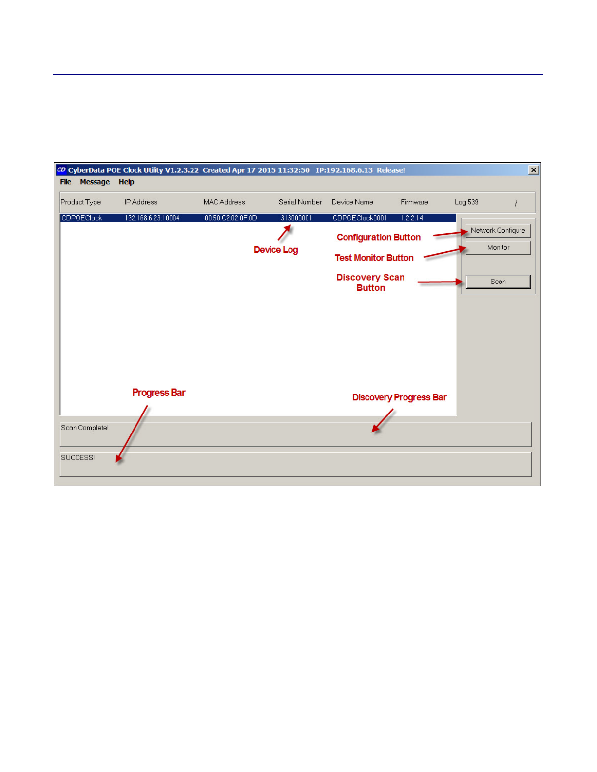
Double-click on the configuration utility shortcut to open the configuration utility program. The Main
Dialog shown in Figure 1-2 appears.
Figure 1-2. Main Dialog
PoE Digital Clock Configuration Utility
Main Dialog
2
Operations Guide 931080C CyberData Corporation
Page 10

PoE Digital Clock Configuration Utility
Main Dialog
Ta bl e 1-1 shows the function of the items that are available on the Main Dialog.
Table 1-1. Main Dialog Items
Item Function
Discovery Scan Button Clicking this button starts Discovery of PoE Digital Clocks that are attached to the Local Area
Network (LAN).
Device Log As PoE Digital Clocks are discovered on the LAN, they will appear as a list in the Device Log.
Network Configure Button Selecting a PoE Digital Clock from the Device Log and clicking this button will open the Network
Configuration Dialog (see Section 1.6, "Network Configuration Dialog") for the selected PoE
Digital Clock.
Test Monitor Button Selecting a PoE Digital Clock from the Device Log and clicking this button will open the Te s t
Monitor Dialog (see Section 1.7, "Test Monitor Dialog") for the selected PoE Digital Clock.
Progress Bar and
Discovery Progress Bar
The Progress Bar and Discovery Progress Bar are constantly being updated. If an error occurs
during Discovery, Configuration, or Testing, messages appearing in the Progress Bars will show
the cause of the error.
3
Operations Guide 931080C CyberData Corporation
Page 11
1.5 Discovery Dialog
Scan buttonTest Monitor buttonConfiguration button
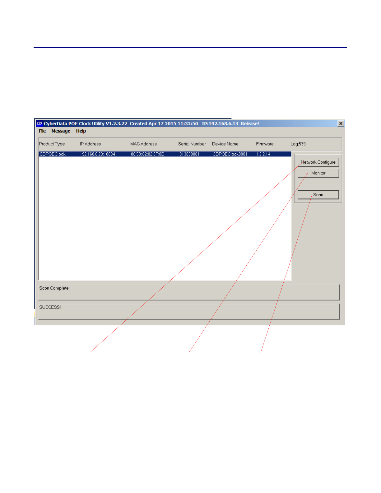
Clicking the Discovery Scan Button starts the discovery of PoE Digital Clocks on the LAN. During
Discovery, the Network Configure Button and Test Monitor Button are not available. When Discovery
completes, a list of PoE Digital Clocks connected to the LAN appears on the Device Log, and then
the Network Configure Button and Test Monitor Button become active.
Figure 1-3. Discovery Dialog
PoE Digital Clock Configuration Utility
Discovery Dialog
4
In Figure 1-3, there is only one PoE Digital Clock connected to the LAN. If there were more PoE
Digital Clocks on the LAN, they would appear as a list of PoE Digital Clocks. The final PoE Digital
Clock discovered is automatically selected. Network Configuration parameters such as IP Address
and MAC Address are listed as well as PoE Digital Clock manufacture information, serial number,
device name, and firmware version.
If more than one PoE Digital Clock appears on the list, click anywhere the list entry to select which
PoE Digital Clock is to be Configured or Tested.
Then click the Network Configure Button or Test Monitor Button to open the Network Configuration
Dialog or Test Monitor Dialog.
Operations Guide 931080C CyberData Corporation
Page 12
1.6 Network Configuration Dialog
Network Configure button
Configuration Dialog
Use DHCPDevice Name Command Port
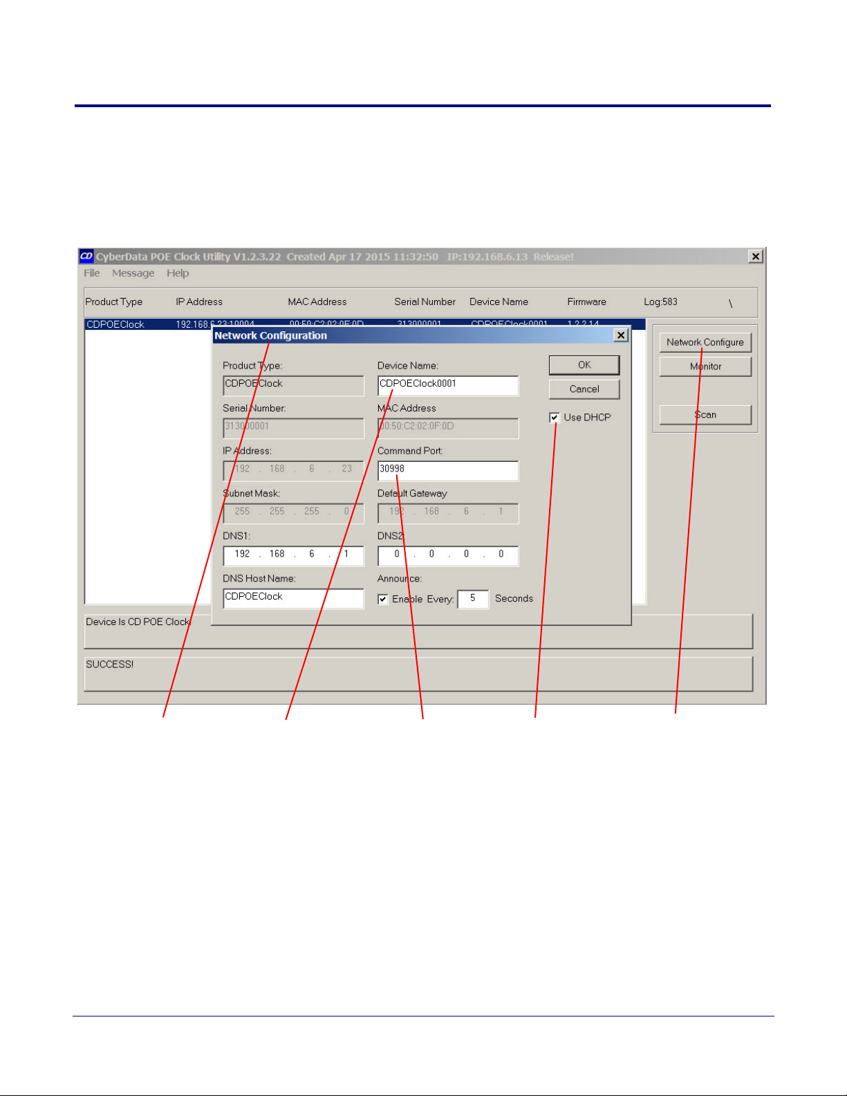
Click on the Network Configure Button to go to the Network Configuration Dialog (see Figure 1-4).
The Network Configuration Dialog allows you to configure the PoE Digital Clock name and LAN
connection variables.
Figure 1-4. Network Configuration Dialog
PoE Digital Clock Configuration Utility
Discovery Dialog
5
Operations Guide 931080C CyberData Corporation
Page 13

PoE Digital Clock Configuration Utility
Discovery Dialog
On the Network Configuration Dialog, you may enter values for the parameters indicated in Tab l e 1-
2.
Table 1-2. Network Configuration Dialog Items
Item Function
Device Name The default PoE Digital Clock name is generated at the time of manufacture and
consists of CDPOEClock appended with the last four digits of the serial number. This
configurable field is a maximum of 16 characters in length and intended to identify one
of many PoE Digital Clocks.
Use DHCP The default setting is IP by DHCP. Disabling DHCP by clicking to removing the check
from the box makes the IP Address, Subnet Mask, and Default Gateway settings
available for static IP configuration.
Command Port In the event the default command port conflicts with other applications using the LAN,
it can be changed to another value. The Command Port is the port to which the PoE
Digital Clock listens for TCP commands on the LAN.
DNS1 & DNS2 DNS server IPs used for DNS lookup of NTP servers for automatic update of date &
time. If DHCP is enabled, DNS IPs are requested from the DHCP server and fulfilled
by the DHCP response.
DNS Host Name
The DNS Host Name is sent to the DHCP server as part of DHCP request.
6
Announce
Checking this box will enable PoE Digital Clock to broadcast a UDP Announce
message at the interval in seconds specified when there is no TCP command
port connection. The Announce feature is a method by which the
PoE Digital Clock
can be detected by a Host without broadcasting a Discover Request.
Operations Guide 931080C CyberData Corporation
Page 14
1.6.1 Static IP Configuration
IP Address DNS Host Name Subnet Mask Default Gateway Use DHCP
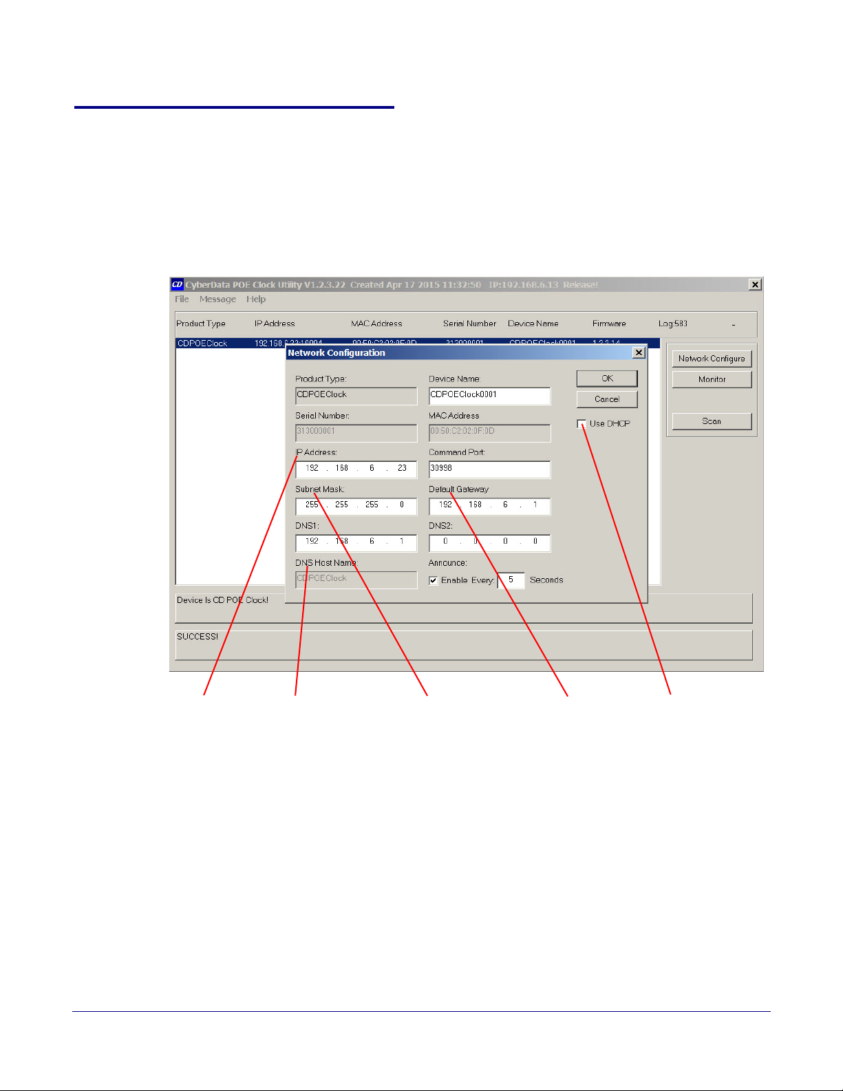
If the Use DHCP check box (Figure 1-5) is not checked, then the following Network Configuration
(Static IP) Dialog appears for static IP configuration.
Note Note that IP Address, Subnet Mask, and Default Gateway fields (Figure 1-5) are now
enabled for change and that the DNS Host Name field is disabled.
Figure 1-5. Network Configuration (Static IP) Dialog
PoE Digital Clock Configuration Utility
Discovery Dialog
7
Operations Guide 931080C CyberData Corporation
Page 15
1.6.2 Configuration Updated Dialog
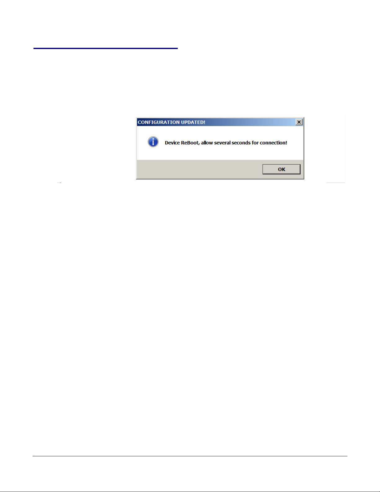
Changes to this configuration page require that the PoE Digital Clock be rebooted. Clicking on the
OK button will send configuration changes to PoE Digital Clock, then cause PoE Digital Clock to
reboot and connect to the LAN with the corrected configuration. This may take several seconds. A
warning dialog appears.
Figure 1-6. Configuration Updated Dialog
Wait 15 seconds for the PoE Digital Clock to implement configuration changes then click on the OK
button.
PoE Digital Clock Configuration Utility
Discovery Dialog
8
A scan of PoE Digital Clocks will automatically be started, and then the Main Dialog (Figure 1-2) will
appear.
Operations Guide 931080C CyberData Corporation
Page 16
1.7 Test Monitor Dialog
Get Status
Firmware Load
Configuration
Load
Configuration
Dump
Format
Colon
Intensity
Use Host TZ, DST,
Date & Time
Time Zone
Daylight Savings
NTP Update
Set Clock
Battery V.
Firmware V.
Build
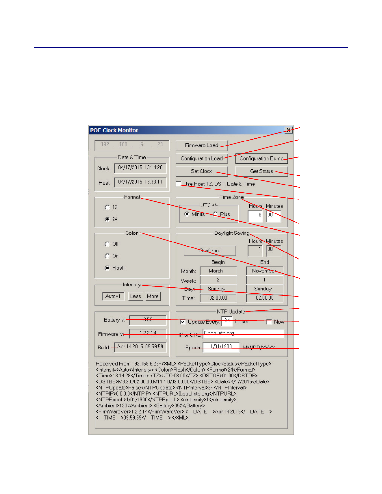
Click on the Monitor button to go to the Test Monitor Dialog (see Figure 1-7). The Test Monitor
Dialog is provided for configuring the PoE Digital Clock timekeeping functionality. Date, Time, Time
Zone, Daylight Saving, and automatic NTP update of the PoE Digital Clock are configured in the Test
Monitor Dialog. 12/24 hour mode, colon appearance, and brightness of the digits are also configured
in the Test Monitor Dialog.
Figure 1-7. Test Monitor Dialog
PoE Digital Clock Configuration Utility
Test Monitor Dialog
9
Operations Guide 931080C CyberData Corporation
Page 17
PoE Digital Clock Configuration Utility
Test Monitor Dialog
On the Test Monitor Dialog, you may enter values for the parameters indicated in Ta bl e 1-3.
Table 1-3. Test Monitor Dialog Items
Item Function
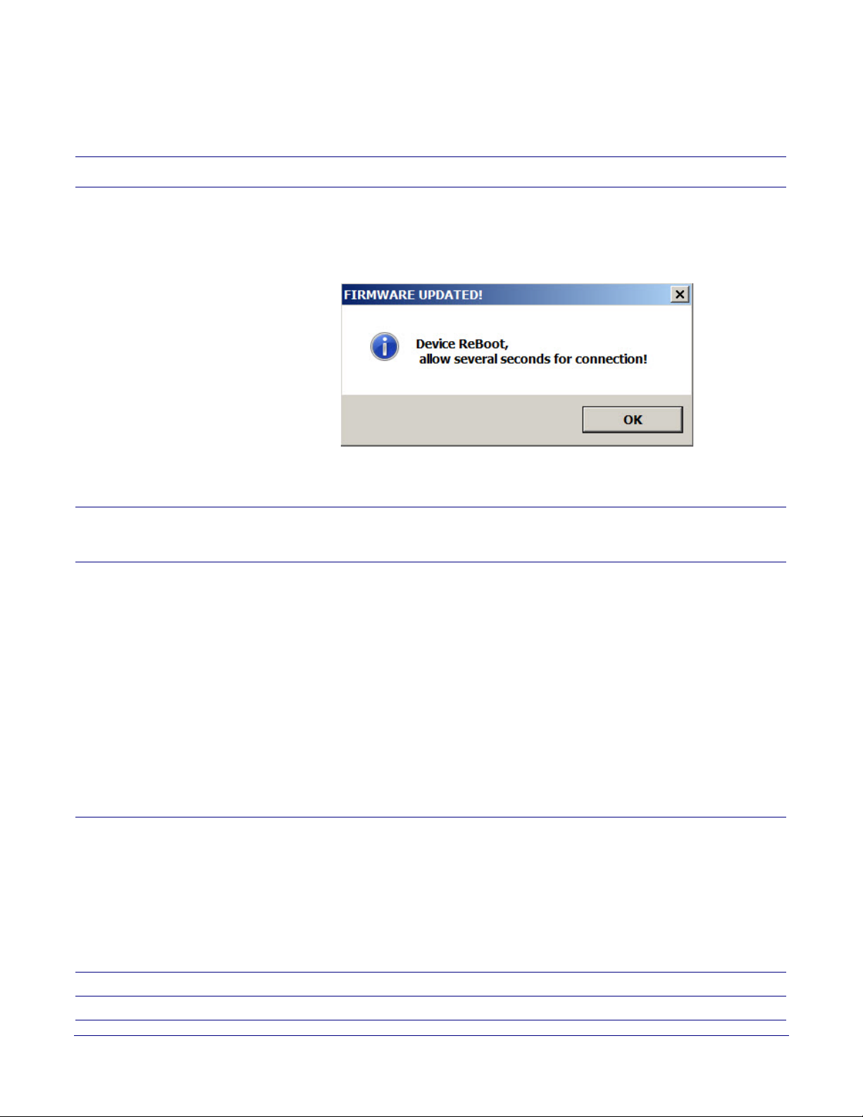
Firmware Load Click this button to update PoE Digital Clock firmware. A standard Windows file dialog
appears. Navigate to the firmware upgrade file and click Open. Firmware will be sent to
PoE Digital Clock from the file. Load progress will be presented at the large progress panel
at the bottom of the dialog. At the end of firmware load, PoE Digital Clock must reboot
which will take some seconds to complete. The following dialog appears:
Wait 15 seconds for the PoE Digital Clock to implement configuration changes, and then
click on the OK button. A scan of PoE Digital Clocks will automatically be started and the
Main Dialog (Figure 1-2) will appear.
Get Status Continuous status may be obtained by clicking the Get Status button. Stop continuous
status by clicking Get Status again. Raw Status Response is displayed at the large
progress panel at the bottom of the dialog.
Configuration Dump The PoE Clock configuration may be saved to an ordinary text file by clicking this button. A
standard Windows file dialog appears. Navigate to a directory that the configuration text file
is to be saved and click the Save button. The PoE Clock configuration will be saved to a
disk file. The configuration file may then be used as a template by configuration software to
propagate PoE Clock configuration from one to many clocks.
The configuration file used as input to the Configuration Load command must be prepared
by software familiar with details of the infrastructure of a specific PoE Clock installation. For
example, if Static IP is to be assigned, a unique IP must be provided. Also, the <DevName>
value should be unique (i.e. Shipping, Engineering, Kitchen, etc.). However, if the
<DevName> value is not unique, then there will be no effect on the function of the PoE
Clock.
Corrected values for Date & Time should be substituted for the values acquired from the
Dump Configuration template. The addition of the "<NTPNOW>True</NTPNOW>" line to
the template will trigger an automatic update of the Date & Time setting if there is internet
access after the Configuration Load command.
10
Configuration Load The PoE Clock configuration may be loaded from an ordinary text file by clicking this button.
A standard Windows file dialog appears. Navigate to the location of the configuration text
file and click the Open button. The PoE Clock configuration will be loaded from the disk file.
Precautions detailed by the Configuration Dump command should be observed in order
that the contents of the Configuration Load text file are appropriate. The PoE Configuration
Utility does not audit the configuration load file prior to issuing a Configuration Load
command. Software familiar with details of infrastructure of a PoE Clock installation should
prepare the configuration load file prior to use as input to a Configuration Load command by
the PoE Configuration Utility.
Format Click 12 or 24 hour format button to select desired format.
Colon Click the desired colon button to select colon appearance.
Operations Guide 931080C CyberData Corporation
Page 18
PoE Digital Clock Configuration Utility
Test Monitor Dialog
Table 1-3. Test Monitor Dialog Items (continued)
Item Function
Intensity Click on the More or Less buttons to roll through the range of desired intensity. Dim is the
least intense. 1 through 15 selects a range of brightness. Auto uses an ambient light sensor
to automatically adjust brightness.
Use Host TZ, DST, Date & Time Check this box for convenience of using the Windows Host settings for these configuration
items. Time Zone, Daylight Saving, Date & Time configuration will be taken from the Host
Pc and automatically updated on the dialog.
Time Zone UTC offset may be manually configured here, +/- UTC, hours and minutes.
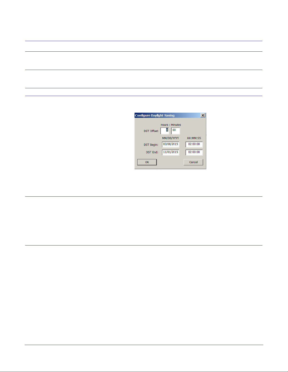
Daylight Saving The Daylight Saving configuration may be manually entered here. Clicking the Configure
button presents a dialog.
11
Enter the values for DST Offset, DST Begin, and DST End, and then click on the OK
button.
Note: Enter zero values for minutes and hours to disable the automatic Daylight Saving
adjustment.
NTP Update Check the Update box and enter the frequency in hours of the automatic time adjustment
from and NTP server. Enter an NTP server URL or an IP address of an NTP server. Be
aware that if a URL is specified, PoE Digital Clock uses the DNS Server IPs from the
network configuration dialog to locate the NTP server by URL.
Check the Now box to test NTP update immediately.
The PoE Digital Clock device accepts “NTP Version 3 answers” from NTP servers. NTP
Epoch should not be changed unless it is certain that the NTP server being addressed uses
another Epoch.
Operations Guide 931080C CyberData Corporation
Page 19
PoE Digital Clock Configuration Utility
Test Monitor Dialog
Table 1-3. Test Monitor Dialog Items (continued)
Item Function
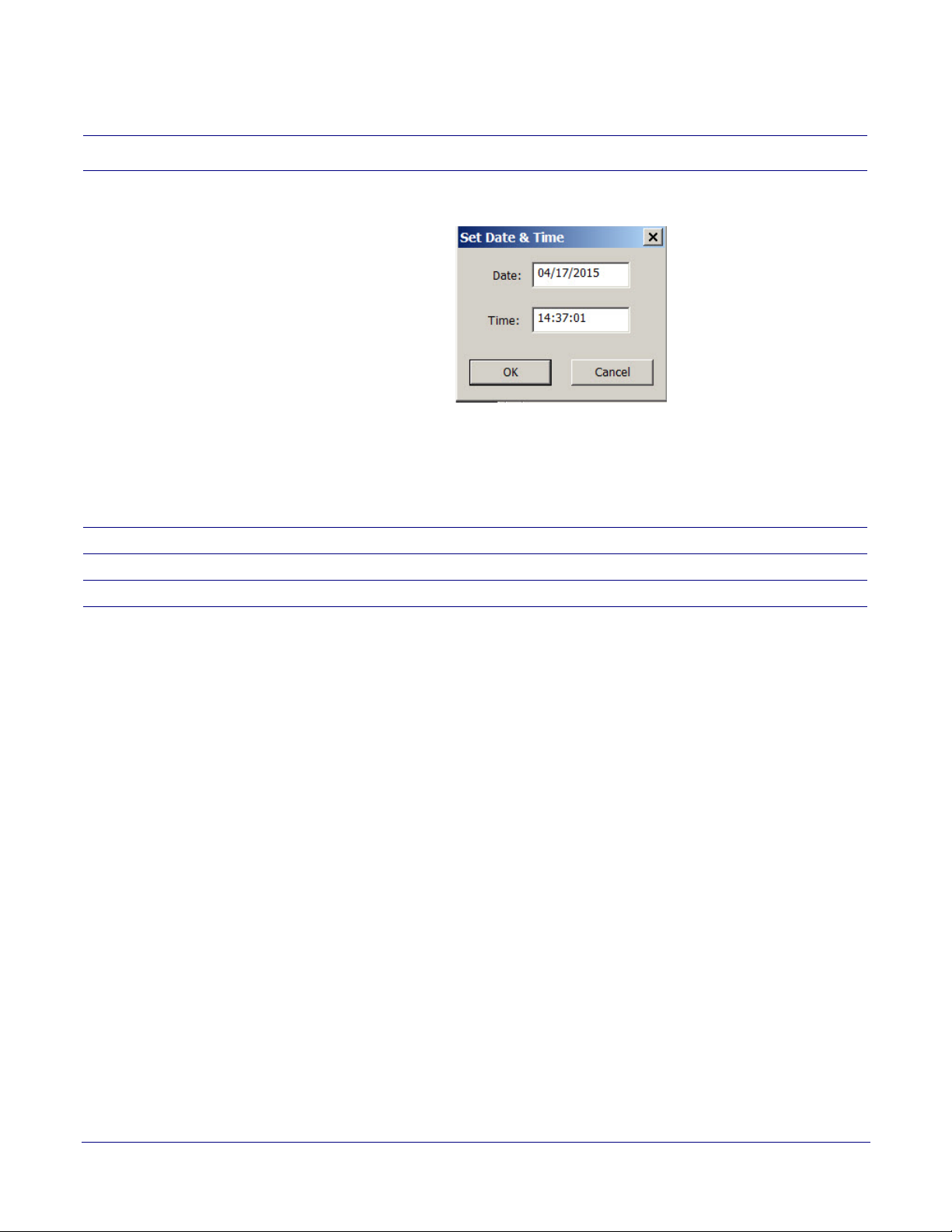
Set Clock After all of the configuration fields have been entered, click the Set Clock button to commit
the configuration fields to the PoE Digital Clock. A dialog appears.
The date and time from the Windows Host PC is presented. Enter the desired date and time
then click on the OK button.
Note: Until the OK button is clicked on the Set Date & Time dialog, none of the format,
colon, intensity, time zone, daylight saving, NTP configuration values have been
committed to the PoE Digital Clock. All of the configuration values are sent to the PoE
Digital Clock in one command message after the Set Date & Time OK button is clicked.
12
Battery V. This shows the PoE Digital Clock battery voltage.
Firmware V. This shows the PoE Digital Clock firmware version number.
Build This shows the PoE Digital Clock firmware build date and time.
Operations Guide 931080C CyberData Corporation
Page 20

2 POE Clock Messages
2.1 UDP Messages Definition
For UDP broadcast commands that are directed to a specific POE Clock, commands are qualified by
matching MacAddr and SerialNum values in the command with internal storage programmed at
manufacture.
2.1.1 Discover
Discover UDP Broadcast is a request from a Host to CDNetDevices, one of which is POE Clock, to
make them known to the Host. CyberData POE Clock receives a UDP broadcast Discover Request
on port 10004 then broadcasts a UDP Discover Response to the port from which the request was
received.
Table 2-1. Discover
13
From >
To
Host >
Device
Device >
Host
Content Comment
<XML>\n
<PacketType>Request</PacketType>\n
<VendorName>CyberData</VendorName>\n
<ProductName>CDNetDevice</ProductName>\n
</XML>\n
<XML>\n
<PacketType>Response</PacketType>\n
<VendorName>CyberData</VendorName>\n
<ProductName>CDNetDevice</ProductName>\n
<ProductType>CDPOEClock</ProductType>\n
<MacAddr>00:50:C2:02:0F:0D</MacAddr>\n
<SerialNum>313000001</SerialNum>\n
<DevName>CDPOEClock0001</DevName>\n
<IPAddr>192.168.6.23</IPAddr>\n
<CMDPort>30998</CMDPort>\n
<SubnetMask>255.255.255.0</SubnetMask>\n
<Gateway>192.168.6.1</Gateway>\n
<DNS1>192.168.6.1</DNS1>\n
<DNS2>0.0.0.0</DNS2>\n
Discover
Request
Discover
Response
Operations Guide 931080C CyberData Corporation
Page 21

Table 2-1. Discover (continued)
<DHCP>Enabled</DHCP>\n
<DNSHostName>CDPOEClock</DNSHostName>\n
<Announce>0</Announce>\n
<S2_SR>0x14 - LISTEN</S2_SR>\n
<DHCPLease>126176</DHCPLease>\n
<FirmWareVer>1.2.2.14</FirmWareVer>\n
<__DATE__>Apr 14 2015</__DATE__>\n
<__TIME__>09:59:59</__TIME__>\n
</XML>\n
POE Clock Messages
14
Operations Guide 931080C CyberData Corporation
Page 22

2.1.2 Announce
If enabled, POE Clock will Announce its presence at a configurable time interval. This relieves Hosts
of issuing Discover requests to determine which devices are connected to a LAN. Announce is a
UDP Broadcast to port 10004.
Table 2-2. Announce
POE Clock Messages
15
From >
To
Device >
Host
Content Comment
<XML>\n
<PacketType>Announce</PacketType>\n
<VendorName>CyberData</VendorName>\n
<ProductName>CDNetDevice</ProductName>\n
<ProductType>CDPOEClock</ProductType>\n
<MacAddr>00:50:C2:02:0F:0D</MacAddr>\n
<SerialNum>313000001</SerialNum>\n
<DevName>CDPOEClock0001</DevName>\n
<IPAddr>192.168.6.23</IPAddr>\n
<CMDPort>30998</CMDPort>\n
<SubnetMask>255.255.255.0</SubnetMask>\n
<Gateway>192.168.6.1</Gateway>\n
<DNS1>192.168.6.1</DNS1>\n
<DNS2>0.0.0.0</DNS2>\n
<DHCP>Enabled</DHCP>\n
<DNSHostName>CDPOEClock</DNSHostName>\n
<Announce>10</Announce>\n
<S2_SR>0x14 - LISTEN</S2_SR>\n
<DHCPLease>125157</DHCPLease>\n
<FirmWareVer>1.2.2.14</FirmWareVer>\n
<__DATE__>Apr 14 2015</__DATE__>\n
<__TIME__>09:59:59</__TIME__>\n
</XML>\n
Announce
Note Announce has the same format and content as Discovery Response.
Operations Guide 931080C CyberData Corporation
Page 23

2.1.3 Change – Static IP
POE Clock will accept a UDP Broadcast to port 10004 to Change Network Configuration. This
example configures POE Clock to Static IP. If the Change packet is accepted, POE Clock responds
by sending a Confirmation packet to the IP and Port which sent the Change packet. If the Change
packet is rejected, POE Clock responds with a Rejection packet.
Table 2-3. Change – Static IP
POE Clock Messages
16
From >
To
Host >
Device
Device >
Host
Content Comment
<XML>\n
<PacketType>Change</PacketType>\n
<VendorName>CyberData</VendorName>\n
<ProductName>CDNetDevice</ProductName>\n
<ProductType>CDPOEClock</ProductType>\n
<MacAddr>00:50:C2:02:0F:0D</MacAddr>\n
<SerialNum>313000001</SerialNum>\n
<DevName>CDPOEClock0001</DevName>\n
<IPAddr>192.168.6.23</IPAddr>\n
<CMDPort>30998</CMDPort>\n
<SubnetMask>255.255.255.0</SubnetMask>\n
<Gateway>192.168.6.1</Gateway>\n
<DHCP>Disable</DHCP>\n
<DNS1>192.168.6.1</DNS1>\n
<DNS2>0.0.0.0</DNS2>\n
<DNSHostName>CDPOEClock</DNSHostName>\n
<Announce>0</Announce>\n
</XML>\n
<XML>\n
<PacketType>Confirmation</PacketType>\n
<VendorName>CyberData</VendorName>\n
<ProductName>CDNetDevice</ProductName>\n
<ProductType>CDPOEClock</ProductType>\n
<MacAddr>00:50:C2:02:0F:0D</MacAddr>\n
<SerialNum>313000001</SerialNum>\n
<Request>Change</Request>\n
</XML>\n
Change
Request
Change
Accepted
Operations Guide 931080C CyberData Corporation
Page 24

Table 2-3. Change – Static IP (continued)
POE Clock Messages
17
Device >
Host
<XML>\n
<PacketType>Rejection</PacketType>\n
<VendorName>CyberData</VendorName>\n
<ProductName>CDNetDevice</ProductName>\n
<ProductType>CDPOEClock</ProductType>\n
<MacAddr>00:50:C2:02:0F:0D</MacAddr>\n
<SerialNum>313000001</SerialNum>\n
<Request>Change</Request>\n
</XML>\n
2.1.4 Change – DHCP IP
This example configures DHCP IP. If the Change packet is accepted, POE Clock responds by
sending a Confirmation packet to the IP and Port which sent the Change packet. If the Change
packet is rejected, POE Clock responds with a Rejection packet.
From >
To
Content Comment
Change
Rejected
Table 2-4. Change – DHCP IP
Host >
Device
<XML>\n
<PacketType>Change</PacketType>\n
<VendorName>CyberData</VendorName>\n
<ProductName>CDNetDevice</ProductName>\n
<ProductType>CDPOEClock</ProductType>\n
<MacAddr>00:50:C2:02:0F:0D</MacAddr>\n
<SerialNum>313000001</SerialNum>\n
<DevName>CDPOEClock0001</DevName>\n
<CMDPort>30998</CMDPort>\n
<DHCP>Enable</DHCP>\n
<DNS1>192.168.6.1</DNS1>\n
<DNS2>0.0.0.0</DNS2>\n
<DNSHostName>CDPOEClock</DNSHostName>\n
<Announce>0</Announce>\n
</XML>\n
Change
Request
Operations Guide 931080C CyberData Corporation
Page 25

Table 2-4. Change – DHCP IP (continued)
POE Clock Messages
18
Device >
Host
Device >
Host
<XML>\n
<PacketType>Confirmation</PacketType>\n
<VendorName>CyberData</VendorName>\n
<ProductName>CDNetDevice</ProductName>\n
<ProductType>CDPOEClock</ProductType>\n
<MacAddr>00:50:C2:02:0F:0D</MacAddr>\n
<SerialNum>313000001</SerialNum>\n
<Request>Change</Request>\n
</XML>\n
<XML>\n
<PacketType>Rejection</PacketType>\n
<VendorName>CyberData</VendorName>\n
<ProductName>CDNetDevice</ProductName>\n
<ProductType>CDPOEClock</ProductType>\n
<MacAddr>00:50:C2:02:0F:0D</MacAddr>\n
<SerialNum>313000001</SerialNum>\n
<Request>Change</Request>\n
</XML>\n
Change
Accepted
Change
Rejected
2.1.5 Reboot
From >
To
Host >
Device
Content Comment
<XML>\n
<PacketType>ReBoot</PacketType>\n
<VendorName>CyberData</VendorName>\n
<ProductName>CDNetDevice</ProductName>\n
<ProductType>CDPOEClock</ProductType>\n
<DevName>CDPOEClock0001</DevName>\n
<MacAddr>00:50:C2:02:0F:0D</MacAddr>\n
<SerialNum>313000001</SerialNum>\n
</XML>\n
POE Clock will accept a UDP Broadcast to port 10004 to reboot. If the ReBoot packet is accepted,
POE Clock responds by sending a Confirmation packet to the IP and Port which sent the ReBoot
packet. If the Change packet is rejected, POE Clock responds with a Rejection packet.
Table 2-5. Reboot
Reboot
Request
Operations Guide 931080C CyberData Corporation
Page 26

Table 2-5. Reboot (continued)
POE Clock Messages
19
Device >
Host
Device >
Host
<XML>\n
<PacketType>Confirmation</PacketType>\n
<VendorName>CyberData</VendorName>\n
<ProductName>CDNetDevice</ProductName>\n
<ProductType>CDPOEClock</ProductType>\n
<MacAddr>00:50:C2:02:0F:0D</MacAddr>\n
<SerialNum>313000001</SerialNum>\n
<Request>ReBoot</Request>\n
</XML>\n
<XML>\n
<PacketType>Rejection</PacketType>\n
<VendorName>CyberData</VendorName>\n
<ProductName>CDNetDevice</ProductName>\n
<ProductType>CDPOEClock</ProductType>\n
<MacAddr>00:50:C2:02:0F:0D</MacAddr>\n
<SerialNum>313000001</SerialNum>\n
<Request>ReBoot</Request>\n
</XML>\n
Reboot
Accepted
Reboot
Rejected
Operations Guide 931080C CyberData Corporation
Page 27

2.1.6 Dump Configuration Command
POE Clock will accept a UDP Broadcast to port 10004 to Dump Configuration. If the Dump
Configuration packet is accepted, POE Clock responds by sending a Configuration Dump packet to
the IP and Port which sent the Dump Configuration packet. This command is intended to be used in
conjunction with Load Configuration command for propagating configuration from one to many POE
Clocks.
Typically a Host would issue a Dump Configuration command to POE Clock, then store the
Configuration Dump response for later input to a Load Configuration command to POE Clocks that
have not yet been configured.
If Static IP is to be configured, the configuration data must be modified for unique IP before using it
as input to Load Configuration.
Table 2-6. Dump Configuration Command
POE Clock Messages
20
From >
To
Host >
Device
Content Comment
<XML>\n
<PacketType>DumpConfiguration</PacketType>\n
<VendorName>CyberData</VendorName>\n
<ProductName>CDNetDevice</ProductName>\n
<ProductType>CDPOEClock</ProductType>\n
<DevName>CDPOEClock0001</DevName>\n
<MacAddr>00:50:C2:02:0F:0D</MacAddr>\n
<SerialNum>313000001</SerialNum>\n
<Sequence>1</Sequence>\n
</XML>\n
Dump
Request
Operations Guide 931080C CyberData Corporation
Page 28

2.1.7 Configuration Dump Response
In response to a Dump Configuration command, POE Clock will send a Configuration Dump
response to the IP and Port which sent the Dump Configuration command.
Table 2-7. Configuration Dump Response
POE Clock Messages
21
From >
To
Device >
Host
Content Comment
<XML>\n
<PacketType>ConfigurationDump</PacketType>\n
<VendorName>CyberData</VendorName>\n
<ProductName>CDNetDevice</ProductName>\n
<ProductType>CDPOEClock</ProductType>\n
<MacAddr>00:50:C2:02:0F:0D</MacAddr>\n
<SerialNum>313000001</SerialNum>\n
<Sequence>0</Sequence>\n
<DevName>CDPOEClock0001</DevName>\n
<IPAddr>192.168.6.23</IPAddr>\n
<CMDPort>30998</CMDPort>\n
<SubnetMask>255.255.255.0</SubnetMask>\n
<Gateway>192.168.6.1</Gateway>\n
<DNS1>192.168.6.1</DNS1>\n
<DNS2>0.0.0.0</DNS2>\n
<DHCP>Enabled</DHCP>\n
<DNSHostName>CDPOEClock</DNSHostName>\n
<Announce>0</Announce>\n
<Intensity>Auto</Intensity>\n
<Colon>Flash</Colon>\n
<Format>24</Format>\n
<Time>11:00:20</Time>\n
<TZ>UTC-08:00</TZ>\n
<DSTOF>01:00</DSTOF>\n
<DSTBE>M3.2.0/02:00:00,M11.1.0/02:00:00</DSTBE>\n
<Date>4/18/2015</Date>\n
<NTPUpdate>False</NTPUpdate>\n
<NTPInterval>24</NTPInterval>\n
<NTPIP>0.0.0.0</NTPIP>\n
Dump
Response
Operations Guide 931080C CyberData Corporation
Page 29

Table 2-7. Configuration Dump Response (continued)
<NTPURL>0.pool.ntp.org</NTPURL>\n
<NTPEpoch>1/01/1900</NTPEpoch>\n
<FirmWareVer>1.2.3.18</FirmWareVer>\n
<__DATE__>Apr 18 2015</__DATE__>\n
<__TIME__>10:46:47</__TIME__>\n
</XML>\n
POE Clock Messages
22
Operations Guide 931080C CyberData Corporation
Page 30

2.1.8 Load Configuration Command
POE Clock will accept a UDP Broadcast to port 10004 to Load Configuration. If the Load
Configuration packet is accepted, POE Clock responds by sending a Confirmation packet to the IP
and Port which sent the Load Configuration command. If the Change packet is rejected, POE Clock
responds with a Rejection packet.
Table 2-8. Load Configuration Command
POE Clock Messages
23
From >
To
Host >
Device
Content Comment
<XML>\n
<PacketType>LoadConfiguration</PacketType>\n
<VendorName>CyberData</VendorName>\n
<ProductName>CDNetDevice</ProductName>\n
<ProductType>CDPOEClock</ProductType>\n
<MacAddr>00:50:C2:02:0F:0D</MacAddr>\n
<SerialNum>313000001</SerialNum>\n
<Sequence>1</Sequence>\n
<DevName>CDPOEClock0001</DevName>\n
<IPAddr>192.168.6.23</IPAddr>\n
<CMDPort>30998</CMDPort>\n
<SubnetMask>255.255.255.0</SubnetMask>\n
<Gateway>192.168.6.1</Gateway>\n
<DNS1>192.168.6.1</DNS1>\n
<DNS2>0.0.0.0</DNS2>\n
<DHCP>Enabled</DHCP>\n
<DNSHostName>CDPOEClock</DNSHostName>\n
<Announce>0</Announce>\n
<Intensity>Auto</Intensity>\n
<Colon>Flash</Colon>\n
<Format>24</Format>\n
<Time>11:00:20</Time>\n
<TZ>UTC-08:00</TZ>\n
<DSTOF>01:00</DSTOF>\n
<DSTBE>M3.2.0/02:00:00,M11.1.0/02:00:00</DSTBE>\n
<Date>4/18/2015</Date>\n
<NTPUpdate>False</NTPUpdate>\n
Dump
Request
Operations Guide 931080C CyberData Corporation
Page 31

Table 2-8. Load Configuration Command (continued)
<NTPInterval>24</NTPInterval>\n
<NTPIP>0.0.0.0</NTPIP>\n
<NTPURL>0.pool.ntp.org</NTPURL>\n
<NTPEpoch>1/01/1900</NTPEpoch>\n
<FirmWareVer>1.2.3.18</FirmWareVer>\n
<__DATE__>Apr 18 2015</__DATE__>\n
<__TIME__>10:46:47</__TIME__>\n
</XML>\n
2.1.9 Load Configuration Response
If the Load Configuration command is accepted, POE Clock responds by sending a Confirmation
packet to the IP and Port which sent the Load Configuration packet. If the Change packet is rejected,
POE Clock responds with a Rejection packet.
Table 2-9. Load Configuration Response
POE Clock Messages
24
From >
To
Device >
Host
Device >
Host
Content Comment
<XML>\n
<PacketType>Confirmation</PacketType>\n
<VendorName>CyberData</VendorName>\n
<ProductName>CDNetDevice</ProductName>\n
<ProductType>CDPOEClock</ProductType>\n
<MacAddr>00:50:C2:02:0F:0D</MacAddr>\n
<SerialNum>313000001</SerialNum>\n
<Sequence>1</Sequence>\n
<Request>LoadConfiguration</Request>\n
</XML>\n
<XML>\n
<PacketType>Rejection</PacketType>\n
<VendorName>CyberData</VendorName>\n
<ProductName>CDNetDevice</ProductName>\n
<ProductType>CDPOEClock</ProductType>\n
<MacAddr>00:50:C2:02:0F:0D</MacAddr>\n
<SerialNum>313000001</SerialNum>\n
<Sequence>1</Sequence>\n
<Request>LoadConfiguration</Request>\n
</XML>\n
Load
Accepted
Load
Rejected
Operations Guide 931080C CyberData Corporation
Page 32

2.2 TCP Messages Definition
2.2.1 Clock Status Request
POE Clock Status Request returns clock configuration parameters having to do with time keeping.
Table 2-10. TCP Messages Definition
POE Clock Messages
TCP Messages Definition
25
From >
To
Host >
Device
Device >
Host
Content Comment
<XML>\n
<PacketType>ClockQuery</PacketType>\n
</XML>\n
<XML>\n
<PacketType>ClockStatus</PacketType>\n
<Intensity>Auto</Intensity>\n
<Colon>Flash</Colon>\n
<Format>24</Format>\n
<Time>16:43:19</Time>\n
<TZ>UTC-08:00</TZ>\n
<DSTOF>01:00</DSTOF>\n
<DSTBE>M3.2.0/02:00:00,M11.1.0/02:00:00</DSTBE>\n
<Date>4/18/2015</Date>\n
<NTPUpdate>False</NTPUpdate>\n
<NTPInterval>24</NTPInterval>\n
<NTPIP>0.0.0.0</NTPIP>\n
<NTPURL>0.pool.ntp.org</NTPURL>\n
<NTPEpoch>1/01/1900</NTPEpoch>\n
<cIntensity>1</cIntensity>\n
<Ambient>86</Ambient>\n
<Battery>353</Battery>\n
<FirmWareVer>1.2.3.18</FirmWareVer>\n
<__DATE__>Apr 18 2015</__DATE__>\n
<__TIME__>10:46:47</__TIME__>\n
</XML>\n
Status
Request
Status
Response
2.2.2 Clock Configuration Command
This POE Clock command configures parameters having to do with time keeping.
Operations Guide 931080C CyberData Corporation
Page 33

Table 2-11. Clock Configuration Command
POE Clock Messages
TCP Messages Definition
26
From >
To
Host >
Device
Content Comment
<XML>\n
<PacketType>ClockCommand</PacketType>\n
Configure
Command
<Intensity>Auto</Intensity>\n
<Colon>Flash</Colon>\n
<Format>24</Format>\n
<Time>17:49:34</Time>\n
<TZ>UTC-8:00</TZ>\n
<DSTOF>1:00</DSTOF>\n
<DSTBE>M3.2.0/02:00:00,M11.1.0/02:00:00</DSTBE>\n
<Date>04/18/2015</Date>\n
<NTPUpdate>False</NTPUpdate>\n
<NTPInterval>24</NTPInterval>\n
<NTPIP>199.102.46.80</NTPIP>
<NTPURL>0.pool.ntp.org</NTPURL>\n
<NTPEpoch>1/01/1900</NTPEpoch>\n
<NTPNOW>True</NTPNOW>\n
</XML>\n
Operations Guide 931080C CyberData Corporation
Page 34

2.2.3 Firmware Upgrade
When POE Clock receives a TCP packet that has the first character colon ‘:’, 0x3a, it enters a mode
that expects firmware upgrade data consisting of an Intel Hex file. Hex load records may be blocked
to a maximum packet size of less than 1Kbytes.
Each load packet is acknowledged with a response indicating the last accepted load address. Lack
of a response indicates bad load data or failure to commit the load data to internal FLASH. Retry the
load packet a finite number of times.
Table 2-12. Firmware Upgrade
POE Clock Messages
TCP Messages Definition
27
From >
To
Host >
Device
Device >
Host :LoadAck Offset=0x0240\n
Content Comment
:020000020000FC\n
:10000000F89448C00C94F62E0C94022F0C940E2FB7\n
:100020000C94952F0C94CE2F0C94DE2F0C94EE2F61\n
:100040000C9455300C9465300C9475300C94B0305D\n
:100060000C9441310C9468310C9474310C94843124\n
:100080000C9417320C9427320C943732800100001F\n
:1000A00000933A0DFF24F4BEF4BE0FE500936000D1\n
:1000C0003C0D0C9429120895721B680D0000000A82\n
:1000E0006F000A3C4C44524D61696E28293E204770\n
:10010000785265634462674F757428293E20547990\n
:1001200020536567203078002C204F66662030784D\n
:1001400021002C204E554C4C21002C204F6B210078\n
:100160000C941A2F0C942A2F0C943A2F0C94692F4D\n
:100180000C9415300C9425300C9435300C94453090\n
:1001A0000C94BE300C94E5300C940C310C94333170\n
:1001C0000C9492310C94B9310C94E0310C94073282\n
:1001E000000000000C944E000C940000F89404B7D1\n
:1002000000936000A8950DB700933B0D0EB700931F\n
:1002C00052660A000A546F0A000A4F660A00204F24\n
:1002E0006F20536C65657021000A3C4C445248655D\n
:100200007065203078002C204C656E203078002C61\n
:10022000002040203078002C2049676E6F72656478\n
:100240002C20486621002C204C6621002C204B66B7\n
Firmware
Upgrade
Hex
Data
Firmware
Upgrade
Accepted
Operations Guide 931080C CyberData Corporation
Page 35

2.3 Definitions
XML tags indentify configuration parameters and status values. These definitions explain the tags
and associated data elements.
2.3.1 <Ambient>
Information only value sensed by the ambient light sensor.
2.3.2 <Announce>
Configurable Announce interval in seconds. Zero value disables Announce. Maximum value is 9999.
Announce relieves Hosts of issuing Discover requests to determine which POE Clocks are
connected to a LAN. Announce is a UDP Broadcast to port 10004.
POE Clock Messages
Definitions
28
2.3.3 <Battery>
Information only value sensed by the battery voltage sensor.
2.3.4 <CMDPort>
Configurable TCP Listen Port. Default 30998 assigned at manufacture.
2.3.5 <Colon>
Configurable colon appearance. “On” is constant on, “Off” is constant off, “Flash” alternates on and
off at one second intervals.
2.3.6 <cIntensity>
If POE Clock is configured for “Auto” intensity, this information only intensity value is determined by
the ambient light sensor.
2.3.7 <Date>
Configurable value specifying current date as “MM/DD/YYYY”. Accurate configuration of this value is
necessary for successful automatic Daylight Saving adjustment and NTP update.
Operations Guide 931080C CyberData Corporation
Page 36

2.3.8 <DevName>
Configurable POE Clock name, 16 characters maximum, i.e. “Loading Dock”, “Kitchen”, etc.
2.3.9 <DHCP>
Configurable DHCP IPv4 parameter. Valid values are “Enable” and “Disable”.
2.3.10 <DHCPLease>
Remaining DHCP lease time in seconds.
2.3.11 <DNS1> & <DNS2>
Configurable IPv4 DNS server addresses used by NTP to locate NTP servers by URL for NTP date
& time update.
POE Clock Messages
Definitions
29
2.3.12 <DNSHostName>
Configurable Host Name included in DHCP request packet used by some routers to identify an
endpoint.
2.3.13 <DSTBE>
Configurable Daylight Saving begin and end expressed in a POSIX-like format. For example,
“M3.2.0/02:00:00,M11.1.0/02:00:01” specifies Daylight Saving begin at Month 3, week 2, Sunday, at
02:00:00, Daylight Saving end Month 11, week 1, Sunday, at 02:00:01. Valid month values are 1-12,
week 1-5, day 0(Sunday)-6(Saturday). Accurate configuration of this parameter value is necessary
for successful automatic Daylight Saving adjustment and NTP update.
2.3.14 <DSTOF>
Configurable Daylight Saving offset expressed as hours and minutes “HH:MM” from Standard Time.
Accurate configuration of this value is necessary for successful automatic Daylight Saving
adjustment and NTP update.
2.3.15 <FirmWareVer>
POE Clock firmware version number.
Operations Guide 931080C CyberData Corporation
Page 37

2.3.16 <Format>
Configurable value “12” or “24”.
2.3.17 <Gateway>
Configurable static IPv4 gateway address or assigned by DHCP.
2.3.18 <IPAddr>
Configurable static IPv4 address or assigned by DHCP.
2.3.19 <Intensity>
Configurable value controls the brightness of the POE Clock display digits “Dim” is the least bright.
Values “1” through “15” select a range of brightness “Auto” uses an ambient light sensor to
automatically adjust brightness.
POE Clock Messages
Definitions
30
2.3.20 <MacAddr>
POE Clock MAC Address is assigned at manufacture.
2.3.21 <NTPEpoch>
Configurable value specifying NTP epoch. POE Clock expects NTP Version 3 answers from NTP
servers. NTP Epoch should not be changed unless it is certain that the NTP server being addressed
uses another Epoch.
2.3.22 <NTPInterval>
Configurable value specifying the interval in hours of automatic update of date and time from a NTP
server. Valid values 1-99.
2.3.23 <NTPIP>
Configurable IPv4 of an NTP server from which automatic NTP update will be taken. If this
parameter contains a valid IPv4 address, it will override NTPURL parameter.
Operations Guide 931080C CyberData Corporation
Page 38

2.3.24 <NTPUpdate>
Configurable value “True” or “False” specifying whether POE Clock will perform automatic update of
date and time from a NTP server.
2.3.25 <NTPURL>
Configurable URL of an NTP server from which automatic NTP update will be taken. Be aware that if
a URL is specified, POE Clock uses DNS Server IPs from the network configuration dialog to locate
the NTP server by URL. Also, if NTPIP parameter contains a valid IPv4 address, it will override
NTPURL parameter.
2.3.26 <PacketType>
The first tag in all packets identifies a packet and its function.
POE Clock Messages
Definitions
31
2.3.27 <ProductName>
Identifies a CyberData CDNetDevice, assigned at manufacture.
2.3.28 <ProductType>
Identifies the CyberData product type, assigned at manufacture.
2.3.29 <Request>
UDP broadcast commands return a Confirmation or Rejection packet. This data element identifies
the Packet Type of the command.
2.3.30 <S2_SR>
POE Clock Ethernet controller TCP command port status indicates the state of the TCP command
port, LISTEN or CONNECTED.
2.3.31 <Sequence>
Dump Configuration and Load Configuration commands and their responses have a sequence
number to provide for multiple commands and responses when configuration data becomes too
large to fit one packet. Currently configuration data fits a single command and response.
Operations Guide 931080C CyberData Corporation
Page 39

2.3.32 <SerialNum>
CyberData serial number, assigned at manufacture.
2.3.33 <SubnetMask>
Configurable static IPv4 subnet mask or assigned by DHCP.
2.3.34 <Time>
Configurable time in 24 hour format “HH:MM:SS”.
2.3.35 <TZ>
Configurable Time Zone expressed as an offset from UTC. For example, California USA time zone is
-08:00, Moscow Russia time zone is +03:00. Accurate configuration of this value is necessary for
successful NTP update.
POE Clock Messages
Definitions
32
2.3.36 <VendorName>
Identifies CyberData as the vendor of POE Clock, assigned at manufacture.
2.3.37 <__DATE__>
Firmware build date.
2.3.38 <__TIME__>
Firmware build time.
2.4 Change Log
2015.04.18 – Initial Version.
Operations Guide 931080C CyberData Corporation
Page 40

Appendix 1: Troubleshooting/Technical Support
Frequently Asked Questions (FAQ)
To see a list of frequently asked questions for your product, click on the FAQs tab at the following
webpage:
http://www.cyberdata.net/voip/011313/
Documentation
The documentation for this product is released in an English language version only.
To download PDF copies of CyberData product documentation, click on the Downloads tab at the
following webpage:
A
http://www.cyberdata.net/voip/011313/
Operations Guide 931080C CyberData Corporation
Page 41

Contact Information
Contact
Sales
Technical
Support
CyberData Corporation
3 Justin Court
Monterey, CA 93940 USA
www.CyberData.net
Phone: 800-CYBERDATA (800-292-3732)
Fax: 831-373-4193
Sales 831-373-2601, Extension 334
The fastest way to get technical support for your VoIP product is to submit a VoIP Technical
Support form at the following website:
http://support.cyberdata.net/
The Support Form initiates a ticket which CyberData uses for tracking customer requests. Most
importantly, the Support Form tells us which PBX system and software version that you are
using, the make and model of the switch, and other important information. This information is
essential for troubleshooting. Please also include as much detail as possible in the Comments
section of the Support Form.
Phone: (831) 373-2601, Extension 333
Warranty and RMA Information
The most recent warranty and RMA information is available at the following website address:
http://support.cyberdata.net/
Operations Guide 931080C CyberData Corporation
Page 42

Index
C
C
Configuration Button 3
contact information B
contact information for CyberData A, B
CyberData contact information B
D
Device Log 3
Discovery Progress Bar 3
Discovery Scan Button 3
F
Firmware Load 10
M
Main Dialog 2
messages definitions 25
W
warranty policy at CyberData B
P
Progress Bar 3
S
sales B
service B
T
TCP messages definitions 25
tech support B
technical support, contact information B
Test Monitor Button 3
Test Monitor Dialog 9
Operations Guide 931080C CyberData Corporation
 Loading...