

Page 1

Singlewire InformaCast
The IP Endpoint Company
Indoor Intercom with
Keypad
Operations Guide
Part #011307
Document Part #931640A
for Firmware Version 20.0.0
CyberData Corporation
3 Justin Court
Monterey, CA 93940
(831) 373-2601
Page 2

Singlewire InformaCast Indoor Intercom with Keypad Operations Guide 931640A
Technical Support
The fastest way to get technical support for your VoIP product is to
submit a VoIP Technical Support form at the following website:
http://support.cyberdata.net/
Phone: (831) 373-2601, Ext. 333
Email: [email protected]
Fax: (831) 373-4193
Company and product information is at www.cyberdata.net.
The IP Endpoint Company
Part # 011307
COPYRIGHT NOTICE:
© 2019, CyberData Corporation, ALL RIGHTS RESERVED.
This manual and related materials are the copyrighted property of CyberData Corporation. No part of
this manual or related materials may be reproduced or transmitted, in any form or by any means
(except for internal use by licensed customers), without prior express written permission of
CyberData Corporation. This manual, and the products, software, firmware, and/or hardware
described in this manual are the property of CyberData Corporation, provided under the terms of an
agreement between CyberData Corporation and recipient of this manual, and their use is subject to
that agreement and its terms.
DISCLAIMER: Except as expressly and specifically stated in a written agreement executed by
CyberData Corporation, CyberData Corporation makes no representation or warranty, express or
implied, including any warranty or merchantability or fitness for any purpose, with respect to this
manual or the products, software, firmware, and/or hardware described herein, and CyberData
Corporation assumes no liability for damages or claims resulting from any use of this manual or such
products, software, firmware, and/or hardware. CyberData Corporation reserves the right to make
changes, without notice, to this manual and to any such product, software, firmware, and/or
hardware.
OPEN SOURCE STATEMENT: Certain software components included in CyberData products are
subject to the GNU General Public License (GPL) and Lesser GNU General Public License (LGPL)
“open source” or “free software” licenses. Some of this Open Source Software may be owned by third
parties. Open Source Software is not subject to the terms and conditions of the CyberData
COPYRIGHT NOTICE or software licenses. Your right to copy, modify, and distribute any Open
Source Software is determined by the terms of the GPL, LGPL, or third party, according to who
licenses that software.
Software or firmware developed by CyberData that is unrelated to Open Source Software is
copyrighted by CyberData, subject to the terms of CyberData licenses, and may not be copied,
modified, reverse-engineered, or otherwise altered without explicit written permission from
CyberData Corporation.
TRADEMARK NOTICE: CyberData Corporation and the CyberData Corporation logos are
trademarks of CyberData Corporation. Other product names, trademarks, and service marks may be
the trademarks or registered trademarks of their respective owners.
CyberData Corporation 931640A Operations Guide
Page 3
Pictorial Alert Icons
GENERAL ALERT
Hazard Levels
Danger: Indicates an imminently hazardous situation which, if not avoided, will result in death or
serious injury. This is limited to the most extreme situations.
Warning: Indicates a potentially hazardous situation which, if not avoided, could result in death or
serious injury.
Caution: Indicates a potentially hazardous situation which, if not avoided, could result in minor or
moderate injury. It may also alert users against unsafe practices.
Notice: Indicates a statement of company policy (that is, a safety policy or protection of property).
The safety guidelines for the equipment in this manual do not purport to address all the safety issues
of the equipment. It is the responsibility of the user to establish appropriate safety, ergonomic, and
health practices and determine the applicability of regulatory limitations prior to use. Potential safety
hazards are identified in this manual through the use of words Danger, Warning, and Caution, the
specific hazard type, and pictorial alert icons.
General Alert
This pictoral alert indicates a potentially hazardous situation. This alert will be
followed by a hazard level heading and more specific information about the
hazard.
Ground
This pictoral alert indicates the Earth grounding connection point.
CyberData Corporation 931640A Operations Guide
Page 4
Important Safety Instructions
GENERAL ALERT
GENERAL ALERT
GENERAL ALERT
1. Read these instructions.
2. Keep these instructions.
3. Heed all warnings.
4. Follow all instructions.
5. Do not use this apparatus near water.
6. Clean only with dry cloth.
7. Do not block any ventilation openings. Install in accordance with the manufacturer’s instructions.
8. Do not install near any heat sources such as radiators, heat registers, stoves, or other apparatus
(including amplifiers) that produce heat.
9. Do not defeat the safety purpose of the polarized or grounding-type plug. A polarized plug has
two blades with one wider than the other. A grounding type plug has two blades and a third
grounding prong. The wide blade or the third prong are provided for your safety. If the provided
plug does not fit into your outlet, consult an electrician for replacement of the obsolete outlet.
10. Protect the power cord from being walked on or pinched particularly at plugs, convenience
receptacles, and the point where they exit from the apparatus.
11. Only use attachments/accessories specified by the manufacturer.
12. Refer all servicing to qualified service personnel. Servicing is required when the apparatus has
been damaged in any way, such as power-supply cord or plug is damaged, liquid has been
spilled or objects have fallen into the apparatus, the apparatus has been exposed to rain or
moisture, does not operate normally, or has been dropped.
13. Prior to installation, consult local building and electrical code requirements.
14. WARNING: The Singlewire InformaCast Indoor Intercom with Keypad enclosure is not
rated for any AC voltages!
War nin g
Electrical Hazard: This product should be installed by a licensed electrician
according to all local electrical and building codes.
War nin g
Electrical Hazard: To prevent injury, this apparatus must be securely attached to
the floor/wall in accordance with the installation instructions.
War nin g
The PoE connector is intended for intra-building connections only and does not
route to the outside plant.
CyberData Corporation 931640A Operations Guide
Page 5

Revision Information
Revision 931640A, which corresponds to firmware version 20.0.0, was released on March 14, 2019.
Browsers Supported
The following browsers have been tested against firmware version 20.0.0:
• Internet Explorer (version: 11)
• Firefox (also called Mozilla Firefox) (version: 62.0)
• Chrome (version: 63.0.3239.132)
• Safari (version: 12)
• Microsoft Edge (version: 42.17134.1.0)
Operations Guide 931640A CyberData Corporation
Page 6

Contents
Chapter 1 Product Overview 1
1.1 How to Identify This Product .....................................................................................................1
1.2 Typical System Installation .......................................................................................................2
1.3 Product Features ......................................................................................................................3
1.4 Supported Protocols .................................................................................................................4
1.5 Supported SIP Servers .............................................................................................................4
1.6 Specifications ...........................................................................................................................5
1.7 Compliance ..............................................................................................................................6
2.1 Parts List ..................................................................................................................................7
Chapter 2 Installing the Singlewire InformaCast Indoor Intercom with Keypad 7
2.2 Intercom Components ..............................................................................................................8
2.3 Intercom Setup .......................................................................................................................10
2.4 Configure the Intercom Parameters ......................................................................................26
2.5 Upgrade the Firmware ............................................................................................................99
2.6 Reboot the Device ................................................................................................................102
2.7 Command Interface ..............................................................................................................103
i
1.7.1 CE Testing ......................................................................................................................6
1.7.2 FCC Statement ..............................................................................................................6
2.2.1 Call Button and Call Button LED ....................................................................................9
2.2.2 Dialing from the Keypad .................................................................................................9
2.3.1 Intercom Connections ..................................................................................................10
2.3.2 Using the On-Board Relay ...........................................................................................12
2.3.3 Wiring the Circuit ..........................................................................................................13
2.3.4 Connecting an Auxiliary RGB Strobe to the Device .....................................................17
2.3.5 Intercom Connectors ....................................................................................................18
2.3.6 Activity and Link LEDs .................................................................................................22
2.3.7 RTFM Button ................................................................................................................23
2.3.8 Adjust the Volume ........................................................................................................25
2.4.1 Factory Default Settings ...............................................................................................26
2.4.2 Intercom Web Page Navigation ....................................................................................27
2.4.3 Using the Toggle Help Button .......................................................................................28
2.4.4 Log in to the Configuration Home Page .......................................................................30
2.4.5 Configure the Device ....................................................................................................34
2.4.6 Configure the Button Parameters .................................................................................39
2.4.7 Configure the Security ..................................................................................................43
2.4.8 Configure the Network Parameters .............................................................................49
2.4.9 Configure the SIP (Session Initiation Protocol) Parameters .........................................51
2.4.10 Configure the SSL Parameters ..................................................................................60
2.4.11 Configure the Multicast Parameters ...........................................................................65
2.4.12 Configure the Access Log Parameters .......................................................................69
2.4.13 Configure the Sensor Configuration Parameters ........................................................71
2.4.14 Configure the Audio Configuration Parameters ..........................................................75
2.4.15 Configure the Events Parameters ..............................................................................81
2.4.16 Configure the Door Strike Relay .................................................................................86
2.4.17 Configure the Autoprovisioning Parameters ...............................................................88
2.7.1 Command Interface Post Commands ........................................................................103
Appendix A Mounting the Singlewire InformaCast Indoor Intercom with
Keypad 106
A.1 Mount the Intercom ..............................................................................................................106
A.2 Dimensions ..........................................................................................................................109
Appendix B Setting up a TFTP Server 111
Operations Guide 931640A CyberData Corporation
Page 7

B.1 Set up a TFTP Server ..........................................................................................................111
B.1.1 In a LINUX Environment ............................................................................................111
B.1.2 In a Windows Environment .......................................................................................111
Appendix C Troubleshooting/Technical Support 112
C.1 Frequently Asked Questions (FAQ) ......................................................................................112
C.2 Documentation .....................................................................................................................112
C.3 Contact Information ..............................................................................................................113
C.4 Warranty and RMA Information ............................................................................................113
Index 114
ii
Operations Guide 931640A CyberData Corporation
Page 8

1 Product Overview
Singlewire Informacast
Indoor Intercom With Keypad
011307* / 021534*
www.cyberdata.net
This device complies with part 15 of the FCC Rules. Operation is subject to the following two conditions: (1)
This device may not cause harmful interference, and (2) this device must accept any interference received,
including interference that may cause undesired operation.
CAN ICES-3 (A)/NMB-3(A)
V20.0.0
00:20:F7:03:83:CA
307200001
Model number
Serial number begins with 3072
1.1 How to Identify This Product
To identify the Singlewire InformaCast Indoor Intercom with Keypad, look for a model number label
similar to the one shown in
• The model number on the label should be 011307.
• The serial number on the label should begin with 3072.
Figure 1-1. Confirm the following:
1
Figure 1-1. Model Number Label
1
1.This figure is just an example. The information on the label of your product may be slightly different.
Operations Guide 931640A CyberData Corporation
Page 9
1.2 Typical System Installation
DC Source
+
1 A @ 30 VDC
Sense Input
Terminal Block of the CyberData Device
Enter key code to trigger the
dry contact in the device
Standard Electronic Door Sense
(not sold by CyberData)
6
5
Standard Electronic Door Strike
(not sold by CyberData)
4
3
3
4
5
6
2
1
7
8
PoE Switch
Trigger electric door strike with a predetermined key code from the IP phone
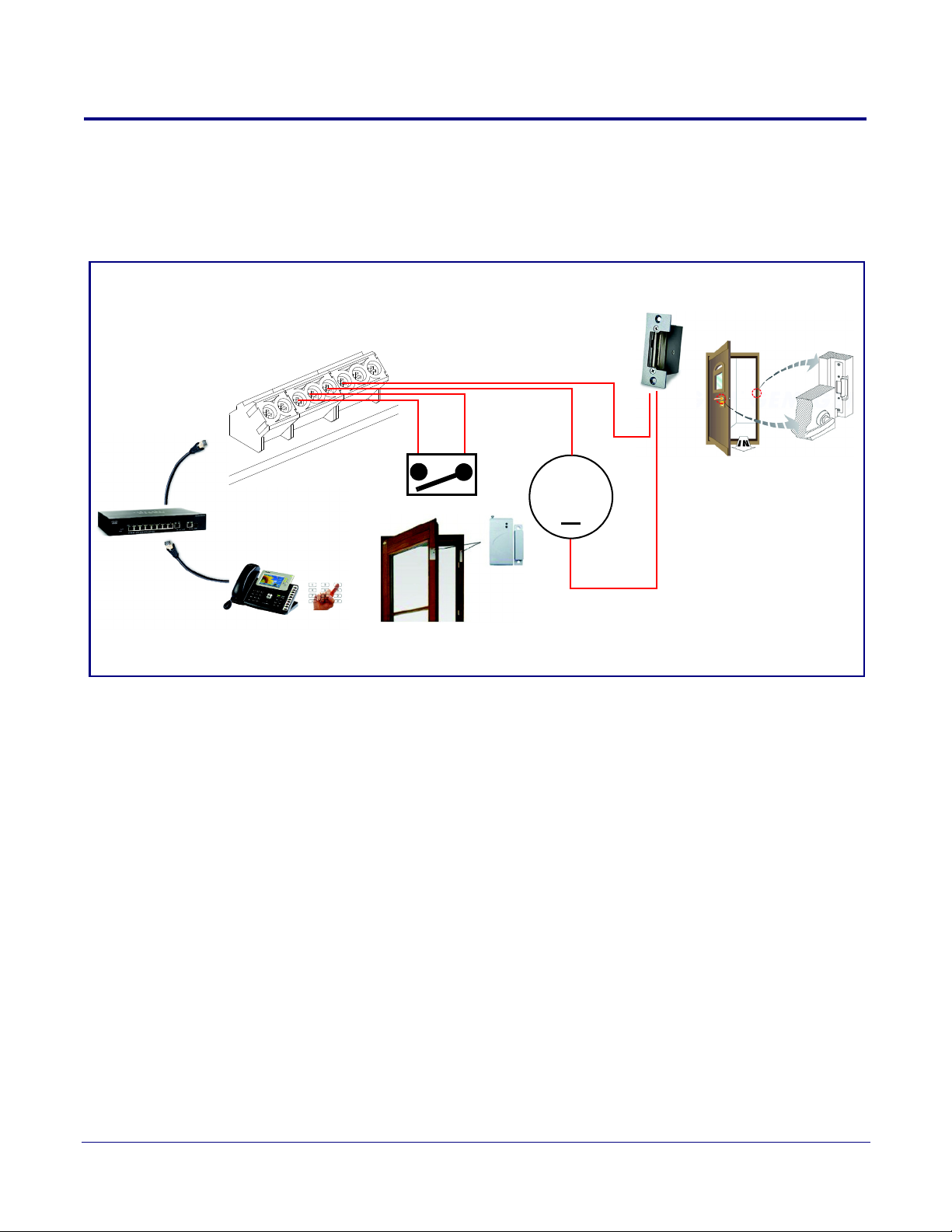
The following figures illustrate how the Singlewire InformaCast Indoor Intercom with Keypad can be
installed as part of a VoIP phone system.
Figure 1-2. Typical Installation
Product Overview
Typical System Installation
2
Operations Guide 931640A CyberData Corporation
Page 10

1.3 Product Features
The Singlewire InformaCast Indoor Intercom with Keypad has the following features:
InformaCast Features
• Capable of receiving Singlewire InformaCast notification messages
• Full duplex voice operation over InformaCast v12.0 or later
• Supports Singlewire InformaCast High Quality Audio
Call Manager Features
• Plays audio from Multicast
• TLS 1.2, enhanced security for IP Endpoints in a local or cloud based environment
• SIP compliant
• Full-duplex voice operation
• Supports SRST (Survivable Remote Site Telephony) in a Cisco environment
• Enhanced acoustic echo canceling
• Network web management and firmware download
• Network adjustable speaker volume
• Concurrent SIP and multicast paging
• Dry relay contact for auxiliary control
• Door closure and tamper alert signal
• Downloadable alert, ringtones and callout messages
Product Overview
Product Features
3
Operations Guide 931640A CyberData Corporation
Page 11

1.4 Supported Protocols
The Intercom supports the following protocols:
•SIP
• Singlewire InformaCast
• Singlewire Failover
• HTTP Web-based configuration
Provides an intuitive user interface for easy system configuration and verification of Intercom
operations.
• DHCP Client
Dynamically assigns IP addresses in addition to the option to use static addressing.
• TFTP Client
Facilitates hosting for the Autoprovisioning configuration file.
•RTP
• RTP/AVP - Audio Video Profile
• TLS 1.2
• Facilitates autoprovisioning configuration values on boot
• Audio Encodings
PCMU (G.711 mu-law)
PCMA (G.711 A-law)
G.722
G.729
Product Overview
Supported Protocols
4
1.5 Supported SIP Servers
The following link contains information on how to configure the device for the supported SIP servers:
https://www.cyberdata.net/pages/connecting-to-ip-pbx-servers
Operations Guide 931640A CyberData Corporation
Page 12

Product Overview
Specifications
1.6
Specifications
Table 1-1. Specifications
Specifications
Ethernet I/F 10/100 Mbps
Protocol SIP RFC 3261 Compatible
Notification Software Singlewire InformaCast v4.0 and above
Power Input PoE 802.3af compliant or +8 to +12VDC @ 1000mA Regulated Power Supply (no
Speaker Output 2 Watts Peak Power
On-Board Relay 1A @ 30 VDC
Payload Types G.711 a-law, G.711 µ-law, G.722, and G.729
Network Security TLS/SSL 1.2
o
Operating Range Temperature: -40
Humidity: 5-95%, non-condensing
o
Storage Temperature
Storage Altitude
Dimensions
Weight
Boxed Weight
Compliance CE; EMC Directive – Class A EN 55032 & EN 55024, LV Safety Directive – EN 60950-1, RoHS
b
C to 70o C (-40o F to 158o F)
-40
Up to 15,000 ft. (4573 m)
7.480 in. [190 mm] Length
2.284 in. [58 mm] Width
5.118 in. [130 mm] Height
2.8 lbs. [1.27 kg]
4.0 lbs. [1.81 kg]
pliant, FCC; Part 15 Class A, Industry Canada; ICES-3 Class A, IEEE 802.3 Compliant
Com
C to 55o C (-40o F to 131o F)
t included)
a
5
Warranty 2 Years Limited
Part Number 011307
a. Contacts 1 and 2 on the terminal block are only for powering the device from a non-PoE 12VDC power source as
an alternative to Network PoE power. Use of these contacts for any other purpose will damage the device and void the
product warranty.
b. Dimensions are measured from the perspective of the product being upright with the front of the product facing you.
Operations Guide 931640A CyberData Corporation
Page 13

1.7 Compliance
1.7.1 CE Testing
CE testing has been performed according to EN ISO/IEC 17050 for Emissions, Immunity, and Safety.
The Declaration of Conformity can be supplied upon request.
1.7.2 FCC Statement
This equipment has been tested and found to comply with the limits for a Class B digital device,
pursuant to part 15 of the FCC Rules. These limits are designed to provide reasonable protection
against harmful interference when the equipment is operated in a commercial environment. This
equipment generates, uses, and can radiate radio frequency energy and, if not installed and used in
accordance with the instruction manual, may cause harmful interference to radio communications.
Operation of this equipment in a residential area is likely to cause harmful interference in which case
the user will be required to correct the interference at his own expense.
Product Overview
Compliance
6
Operations Guide 931640A CyberData Corporation
Page 14
2 Installing the Singlewire InformaCast Indoor Intercom with Keypad
2.1 Parts List
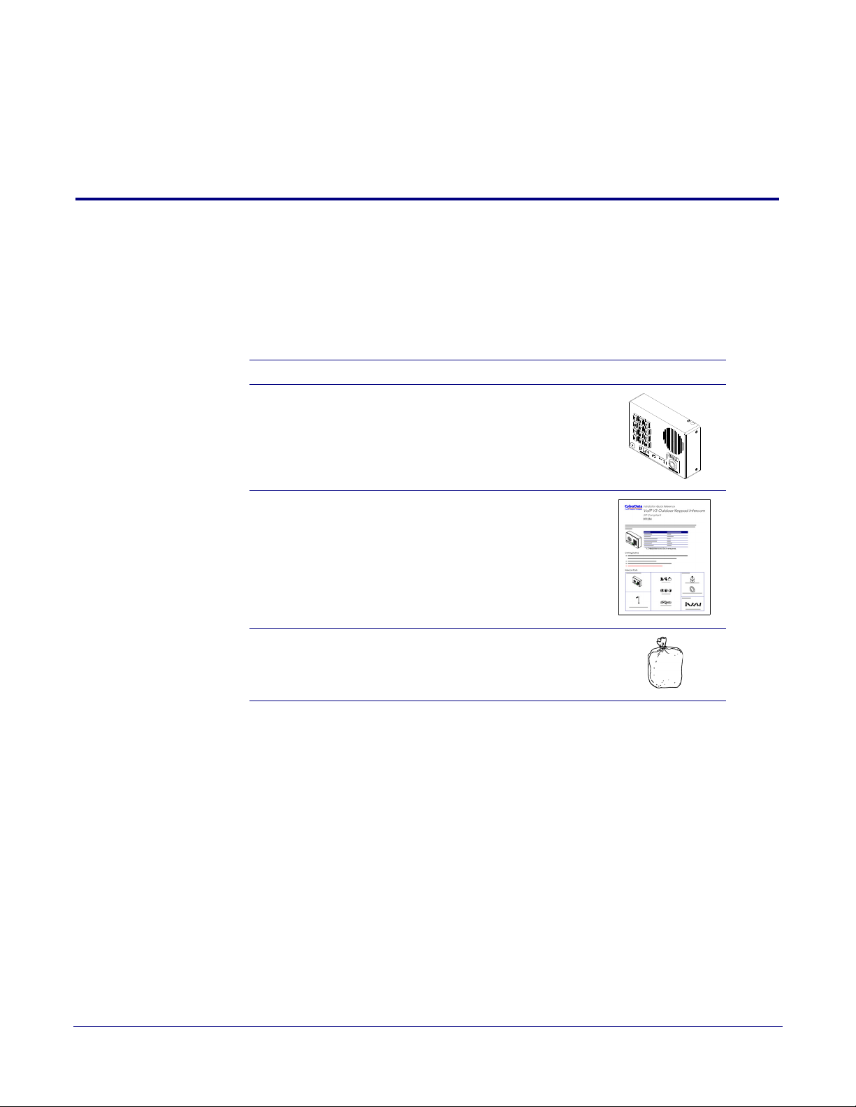
Ta bl e 2-2 illustrates the parts for the Singlewire InformaCast Indoor Intercom with Keypad.
Note See Appendix A, "Mounting the Singlewire InformaCast Indoor Intercom with Keypad" for
physical mounting information.
Table 2-2. Parts List
Quantity Part Name Illustration
1 Singlewire InformaCast Indoor Intercom with
Keypad Assembly
7
1 Installation Quick Reference Guide
1 Mounting Accessory Kit
Operations Guide 931640A CyberData Corporation
Page 15
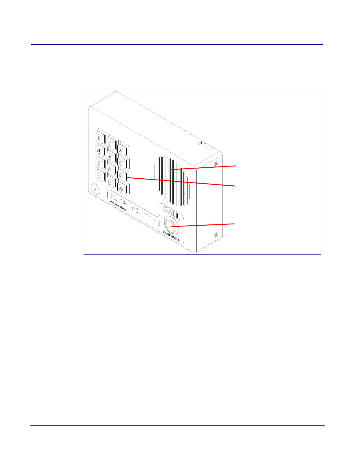
2.2 Intercom Components
Call Button
Speaker Drain Hole
See Section 2.2.1, "Call Button
and Call Button LED" for
information about the functionality
of the Call Button.
Keypad
See Section 2.2.2, "Dialing from
the Keypad" for
information about the functionality
of the keypad.
Figure 2-3 shows the components of the Intercom.
Figure 2-3. Intercom Components
Installing the Singlewire InformaCast Indoor Intercom with Keypad
8
Operations Guide 931640A CyberData Corporation
Page 16
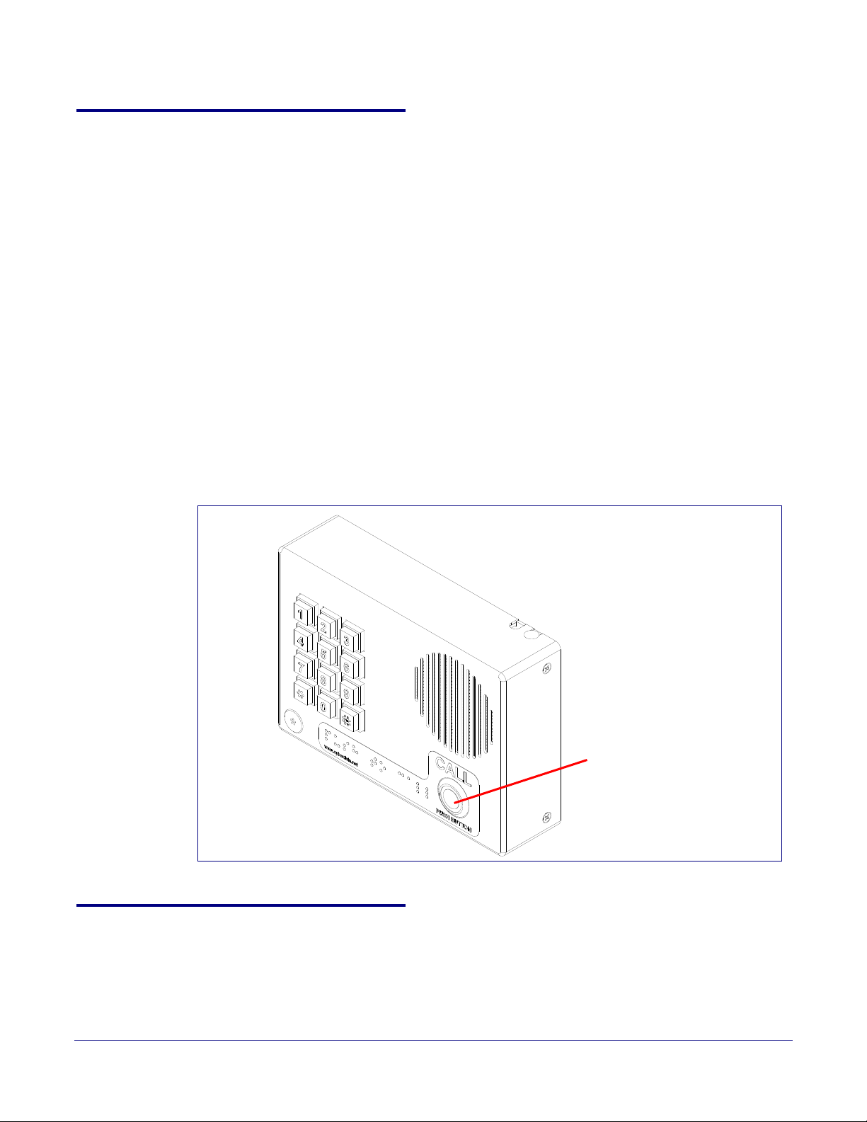
2.2.1 Call Button and Call Button LED
Call button and Call Button LED
2.2.1.1 Call Button LED Function
• Upon initial power or reset, the Call Button LED will illuminate.
• During network setup the Call Button LED will blink 10 times per second until the device can find
a network address. This can take from 5 to 60 seconds.
• The device “autoprovisions” by default, and the initial process may take several minutes as the
device searches for and downloads updates. The Call Button LED will blink during this process.
During the initial provisioning, or after the factory defaults have been reset, the device may
download firmware twice. The device will blink, remain solid for 10 to 20 seconds, and then
resume blinking. This process will take longer if there are many audio files downloading.
• When the software has finished initialization, the Call Button LED will blink twice.
• When a call is established (not just ringing), the Call Button LED will blink.
• On the Device Configuration Page, there is an option called Button and Keypad Lit when
Idle. This option sets the normal state for the Call Button LED. The Call Button LED will still blink
during initialization and calls.
• The Call Button LED flashes briefly at the beginning of RTFM mode.
Installing the Singlewire InformaCast Indoor Intercom with Keypad
Call Button and Call Button LED
9
Figure 2-4. Call Button and Call Button LED
2.2.2 Dialing from the Keypad
• See the Enable Telephone Operation setting in Section 2.4.6, "Configure the Button
Parameters".
Operations Guide 931640A CyberData Corporation
Page 17
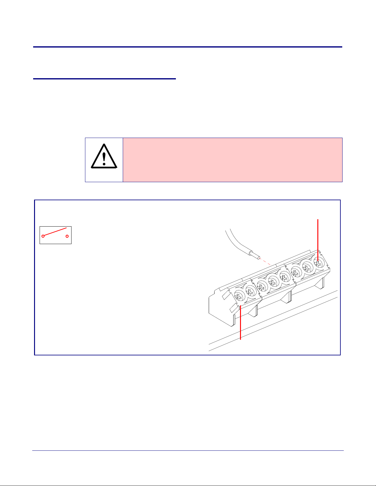
2.3 Intercom Setup
GENERAL ALERT
1
8
Tin Leads
Approx. 1/4” or
6mm
Terminal Block
can accept 16 AWG wire
Alternate Power Input:
1 = +8 to +12VDC @ 1000mA Regulated Power Supply*
2 = Power Ground*
Relay Contact:
(1 A at 30 VDC for continuous loads)
3 = Relay Common
4 = Relay Normally Open Contact
5 = Sense Input
6 = Sense Ground
7 = Remote Switch "A"
8 = Remote Switch "B"
*Contacts 1 and 2 on the terminal block are only for
powering the device from a non-PoE 12VDC power
source as an alternative to Network PoE power. Use of
these contacts for any other purpose will damage the
device and void the product warranty.
3
4
Use a 3.17 mm (1/8-inch) flat blade
screwdriver for the terminal block screws
2.3.1 Intercom Connections
Figure 2-5 shows the pin connections on the terminal block. This terminal block can accept
16 AWG gauge wire.
Installing the Singlewire InformaCast Indoor Intercom with Keypad
Intercom Connections
10
Note As an alternative to
Power Supply into the terminal block.
Caution
Equipment Hazard: Contacts 1 and 2 on the terminal block are only for powering
the device from a non-PoE 12 VDC power source as an alternative to Network PoE
power. Use of these contacts for any other purpose will damage the device and void
the product warranty.
Figure 2-5. Connections and Alternate Power Input
using PoE power, you can supply +8 to +12VDC @ 1000mA Regulated
Wire (IN)
Operations Guide 931640A CyberData Corporation
Page 18
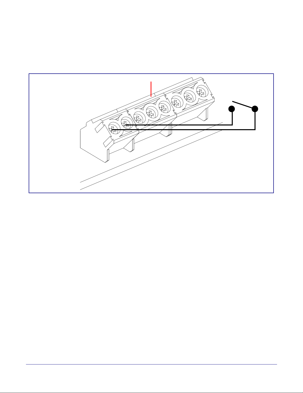
2.3.1.1 Remote Switch Connection
1
8
Terminal Block
Wiring pins 7 and 8 of the terminal block to a switch will initiate a SIP call when the switch is closed.
The call will go to the extension specified as the dial out extension on the SIP page.
Figure 2-6. Remote Switch Connection
Installing the Singlewire InformaCast Indoor Intercom with Keypad
Intercom Connections
11
Operations Guide 931640A CyberData Corporation
Page 19
2.3.2 Using the On-Board Relay
GENERAL ALERT
GENERAL ALERT
GENERAL ALERT
Warning
Electrical Hazard: This product should be installed by a licensed electrician
according to all local electrical and building codes.
Warning
Electrical Hazard: The relay contacts are dry and provided for a normally open
and momentarily closed configuration. Neither the alternate power input nor PoE
power can be used to drive a door strike.
Warning
Electrical Hazard: The relay does not support AC powered door strikes.
Any use of this relay beyond its normal o
product and is not covered under our warranty policy.
Installing the Singlewire InformaCast Indoor Intercom with Keypad
Using the On-Board Relay
perating range can cause damage to the
12
The device has a built-in relay that can be activated by a web configurable DTMF string that can be
received from a VoIP phone supporting out of band (RFC2833) DTMF as well as a number of other
triggering events. See the Device Configuration Page on the web interface for relay settings.
This relay can be used to trigger low current devices like LED strobes and security camera input
signals as long as the load is not an indu
1 Amp @ 30 VDC. Inductive loads can cause excess
ctive type and the relay is limited to a maximum of
ive “hum” and can interfere with or damage the
unit’s electronics.
We highly recommend that inductive load and high current de
vices use our Networked Dual Door
Strike Relay (CD# 011375) (see Section 2.3.3.2, "Network Dual Door Strike Relay Wiring Diagram
with External Power Source").
This relay interface also has a general purpose input port that can be used to monitor an external
s
witch and generate an event.
For more information on the sensor options, see the Sensor Configuration Page on the web
interface.
Operations Guide 931640A CyberData Corporation
Page 20
2.3.3 Wiring the Circuit
1
8
DC Source
+
1 A @ 30 VDC
Sense Input
LED Strobe Light
Terminal Block of the CyberData Device
The terminal block can accept 16 AWG stranded wire.
Pin 3 - Relay Common
Pin 4 - Relay Normally Open Contact
Pin 5 - Sense Input
Pin 6 - Sense Ground
+
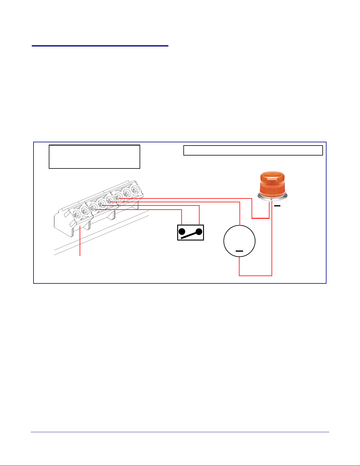
2.3.3.1 Devices Less than 1A at 30 VDC
If the power for the device is less than 1A at 30 VDC and is not an inductive load, then see
Figure 2-7 for the wiring diagram.
When configuring with an inductive load, please use an intermediary relay with a High PIV Ultrafast
Switching Diode. We recommend using the Network Dual Door Strike Relay (CD# 011375) (see
Section 2.3.3.2, "Network Dual Door Strike Relay Wiring Diagram with External Power Source").
Figure 2-7. Devices Less than 1A at 30 VDC
Installing the Singlewire InformaCast Indoor Intercom with Keypad
Wiring the Circuit
13
Operations Guide 931640A CyberData Corporation
Page 21
Installing the Singlewire InformaCast Indoor Intercom with Keypad
GENERAL ALERT
Sense Input 2
DC Source 2
AC Source 2
OR
+
802.3af Compliant Ethernet Switch
CyberData
Aux Button 2
Device
The relay connection maximum wire
size is 12 gauge stranded wire.
Door Strike
Sense Input 1
DC Source 1
AC Source 1
OR
+
Aux Button1
*
Door Strike
*
GENERAL ALERT
*Caution
Equipment Hazard: The door strike must have an internal or external mov or
diode (for over voltage protection) when connecting directly to the module.
See the Network Dual Door Strike Relay
Operations Guide for connection specifics.
See Section 2.4.16, "Configure the Door Strike
Relay" for configuration options.
Wiring the Circuit
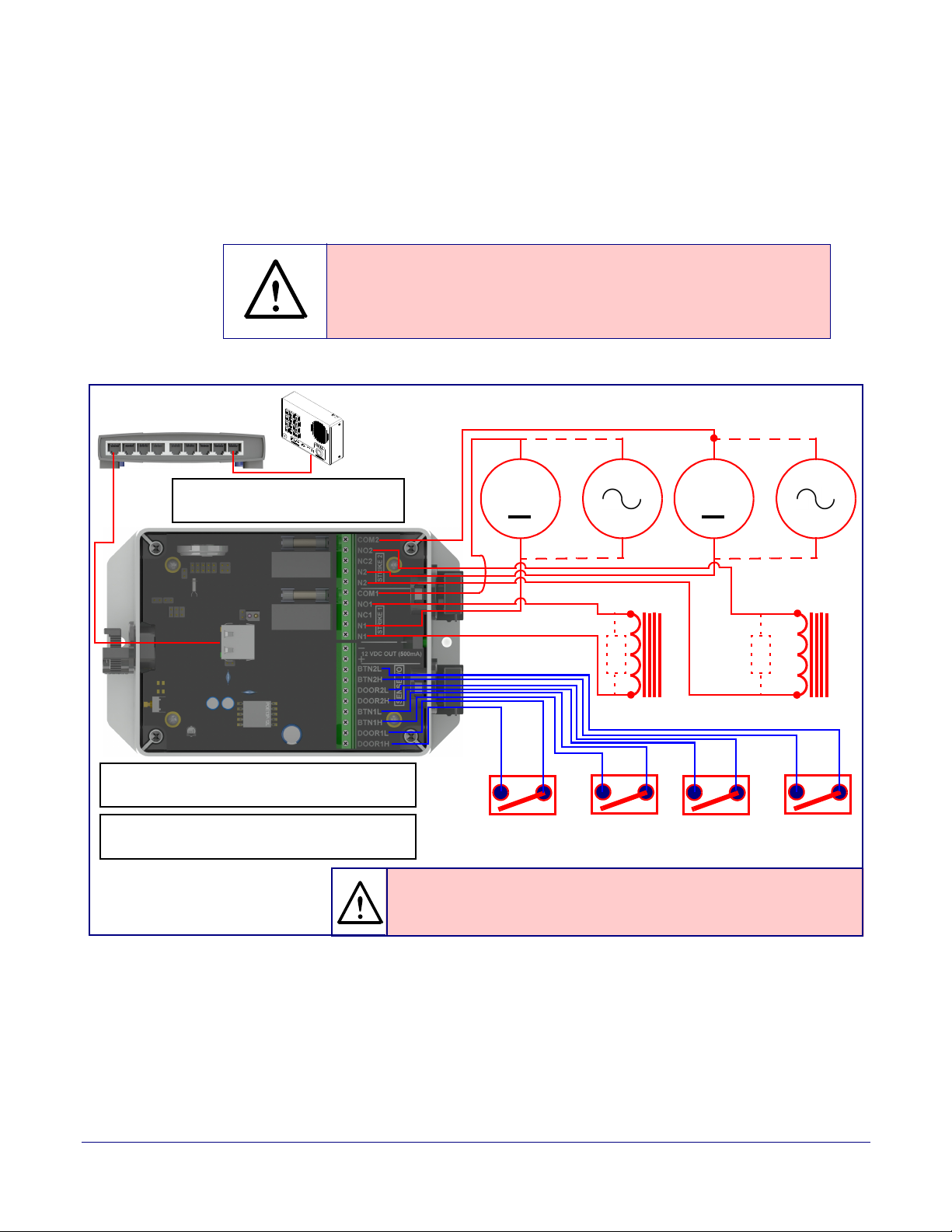
2.3.3.2 Network Dual Door Strike Relay Wiring Diagram with External Power Source
For wiring an electronic door strike to work over a network, we recommend the use of our external
Network Dual Door Strike Relay (CD# 011375).
This product provides an easier method of connecting standard door strikes as well as AC and
h
igher voltage devices. See Figure 2-8 and Figure 2-9 for the wiring diagrams.
War nin g
Electrical Hazard: Hazardous voltages may be present. No user serviceable
part inside. Refer to qualified service personnel for connecting or servicing.
Figure 2-8. Network Dual Door Strike Relay Wiring Diagram with External Power Source
14
Operations Guide 931640A CyberData Corporation
Page 22
Installing the Singlewire InformaCast Indoor Intercom with Keypad
Sense Input 2 Aux Button 2Sense Input 1 Aux Button1
Door Strike
*
Door Strike
*
802.3at Compliant Ethernet Switch
Internal 12VDC
source (500 mA
maximum)
GENERAL ALERT
*Caution
Equipment Hazard: The door strike must have an internal or external mov or
diode (for over voltage protection) when connecting directly to the module.
See the Network Dual Door Strike Relay
Operations Guide for connection specifics.
See Section 2.4.16, "Configure the Door Strike
Relay" for configuration options.
CyberData
Device
The relay connection maximum wire
size is 12 gauge stranded wire.
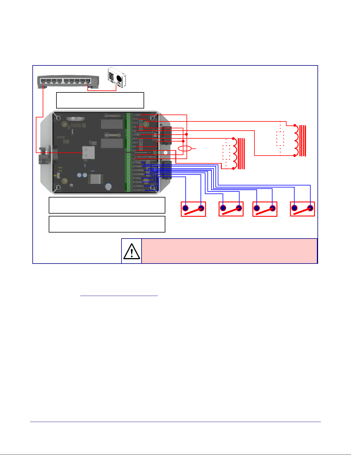
2.3.3.3 Network Dual Door Strike Relay Wiring Diagram Using PoE+
Figure 2-9. Network Dual Door Strike Relay Wiring Diagram Using PoE+
Wiring the Circuit
15
If you have questions about connecting door strikes or setting up the web configurable options,
please contact our support department at the following website:
http://support.cyberdata.net/
Operations Guide 931640A CyberData Corporation
Page 23
Installing the Singlewire InformaCast Indoor Intercom with Keypad
Door Lock Sense Input
The terminal block can accept 16 AWG stranded wire.
DC Source
AC Source
OR
+
1
8
Terminal Block
See the Door Strike Relay Operations Guide for
connection specifics.
See Section 2.4.16, "Configure the Door Strike
Relay" for configuration options.
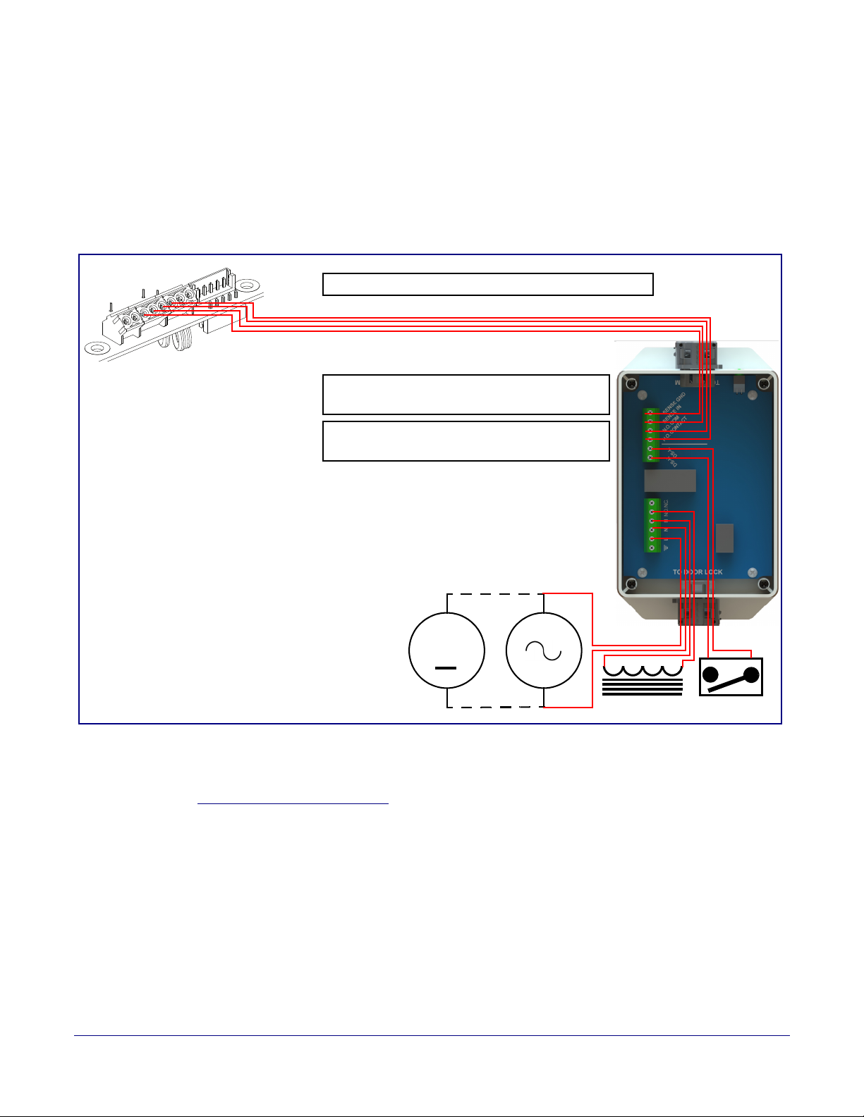
2.3.3.4 Door Strike Relay Module Wiring Diagram from Intercom
For wiring an electronic door strike, we recommend the use of our external Door Strike Relay Module
(CD# 011269).
This product provides an easier method of connecting standard door strikes as well as AC and
higher voltage devices. See
Figure 2-10. Door Strike Relay Module Wiring Diagram from Intercom
Figure 2-10 for the wiring diagram.
Wiring the Circuit
16
If you have questions about connecting door strikes or setting up the web configurable options,
please contact our support department at the following website:
http://support.cyberdata.net/
Operations Guide 931640A CyberData Corporation
Page 24
Installing the Singlewire InformaCast Indoor Intercom with Keypad
J1
JX
Device Board
Auxiliary RGB Strobe Board
Connecting an Auxiliary RGB Strobe to the Device
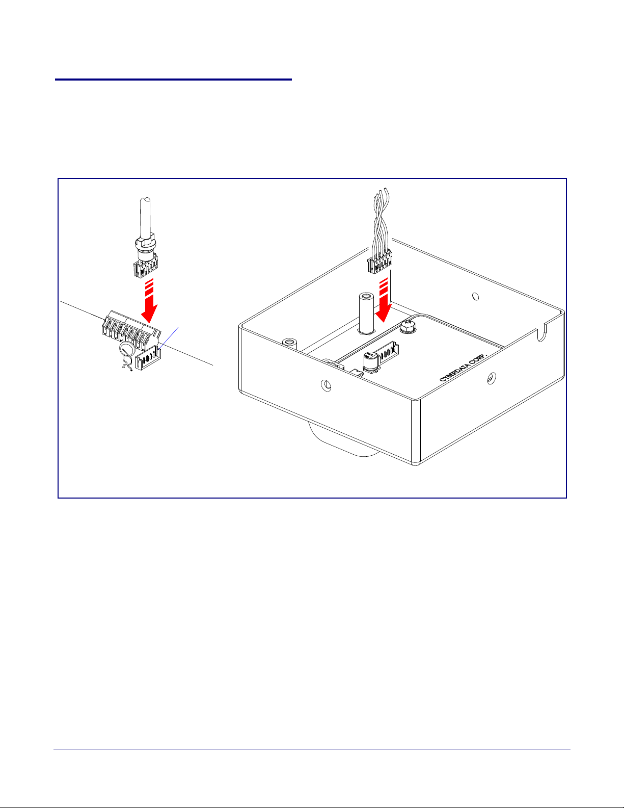
2.3.4 Connecting an Auxiliary RGB Strobe to the Device
1. Connect the strobe cable to the board of the Auxiliary RGB Strobe and the board of the device
as shown in Figure 2-11. Please see the Auxiliary RGB Strobe Operations Guide for more
information about this product.
Figure 2-11. Connecting the Auxiliary RGB Strobe Kit to the Device
17
Operations Guide 931640A CyberData Corporation
Page 25
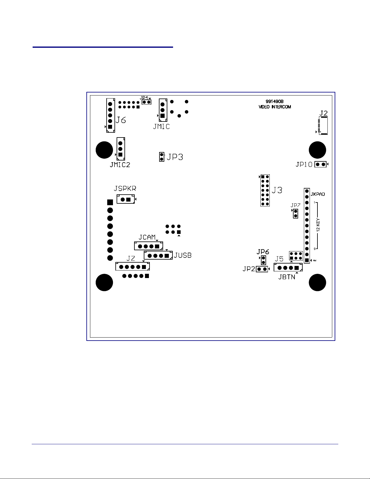
2.3.5 Intercom Connectors
See the following figures and tables to identify the connectors and functions of the Intercom.
Installing the Singlewire InformaCast Indoor Intercom with Keypad
Figure 2-12. Connector Locations—Board Top
Intercom Connectors
18
Operations Guide 931640A CyberData Corporation
Page 26

Installing the Singlewire InformaCast Indoor Intercom with Keypad
Table 2-3. Connector Functions—Board Top
Connector Function
JBTN Call Button LED Interface
JMIC Microphone Interface
JMIC2 Second Microphone Interface (Not Used)
JSPKR Speaker Interface
JKPAD Keypad Interface (Not Used)
JUSB USB Interface (Not Used)
JZ I²C 5V Peripheral Bus
J2 Biometric Interface (Not Used)
J3 JTAG Interface (Not Used)
J5 ISP AT-Tiny Interface (Factory Only)
J6 Digital Microphone Interface (Not Used)
JP3 Mute Disable Jumper—Jumper should be removed
JP6 Enable AT-Tiny—Jumper should be installed
Intercom Connectors
19
JP7 Enable Write to EEPROM—Jumper should be installed
JP10 Disables the intrusion sensor when installed.
Operations Guide 931640A CyberData Corporation
Page 27
Installing the Singlewire InformaCast Indoor Intercom with Keypad
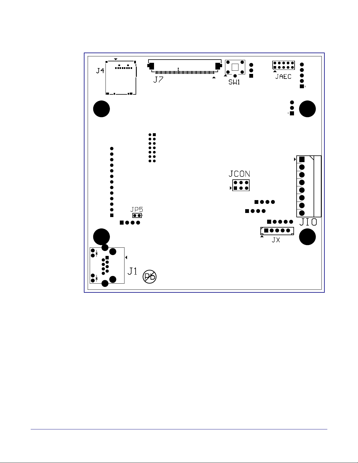
Figure 2-13. Connector Locations—Board Bottom
Intercom Connectors
20
Operations Guide 931640A CyberData Corporation
Page 28

Installing the Singlewire InformaCast Indoor Intercom with Keypad
Intercom Connectors
Table 2-4. Connector Functions—Board Bottom
Connector Function
J1 PoE Network Connection (RJ-45 ethernet)
J4 SD Card Slot
JAEC AEC Configuration Interface (Factory Use Only)
JCON Console Port (Factory Use Only)
JIO Terminal Block (see Figure 2-5)
JP5 Reset jumper
a
JX Auxiliary Strobe Connector
SW1 See Section 2.3.7, "RTFM Button"
a.Do not install a jumper. Momentary short to reset. Permanent installation of a jumper would
prevent the board from running all together.
21
Operations Guide 931640A CyberData Corporation
Page 29
Installing the Singlewire InformaCast Indoor Intercom with Keypad
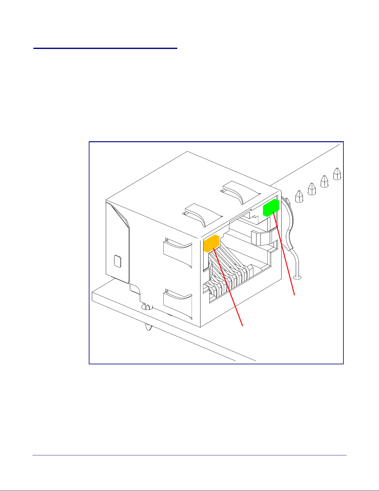
Link/Activity
100 Mb Link
2.3.6 Activity and Link LEDs
2.3.6.1 Verifying the Network Connectivity and Data Rate
When you plug in the Ethernet cable or power supply to the Intercom, the following occurs:
• The square, GREEN Link/Activity LED blinks when there is network activity (see Figure 2-14).
• The square, AMBER 100 Mb Link LED above the Ethernet port indicates that the
network 100 Mb connection has been established (see Figure 2-14).
Figure 2-14. Activity and Link LED
Activity and Link LEDs
22
Operations Guide 931640A CyberData Corporation
Page 30
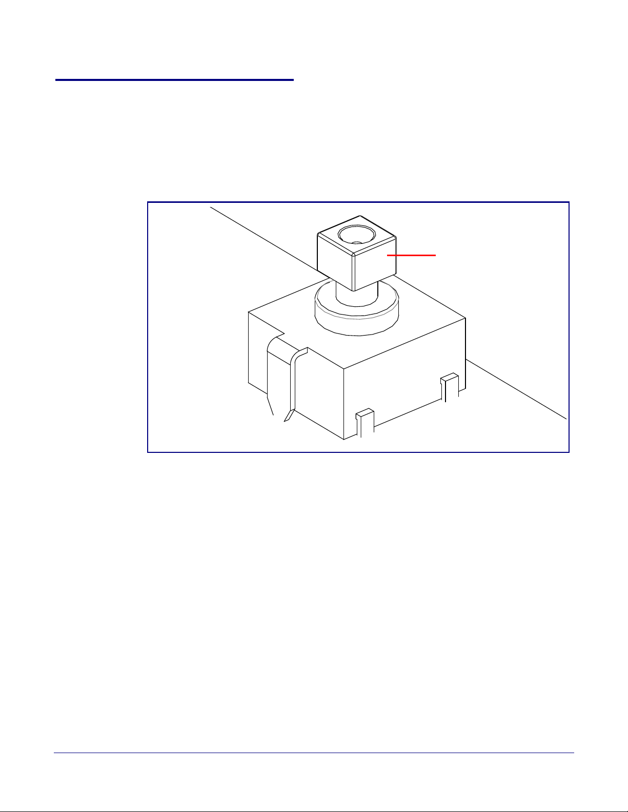
2.3.7 RTFM Button
RTFM button (SW1)
When the Intercom is operational and linked to the network, you can use the Reset Test Function
Management (RTFM) button (see SW1 in
confirm the Intercom’s IP Address and test to see if the audio is working.
Note You must do these tests prior to final assembly.
Installing the Singlewire InformaCast Indoor Intercom with Keypad
Figure 2-15) on the Intercom board to announce and
Figure 2-15. RTFM Button (SW1)
RTFM Button
23
Operations Guide 931640A CyberData Corporation
Page 31
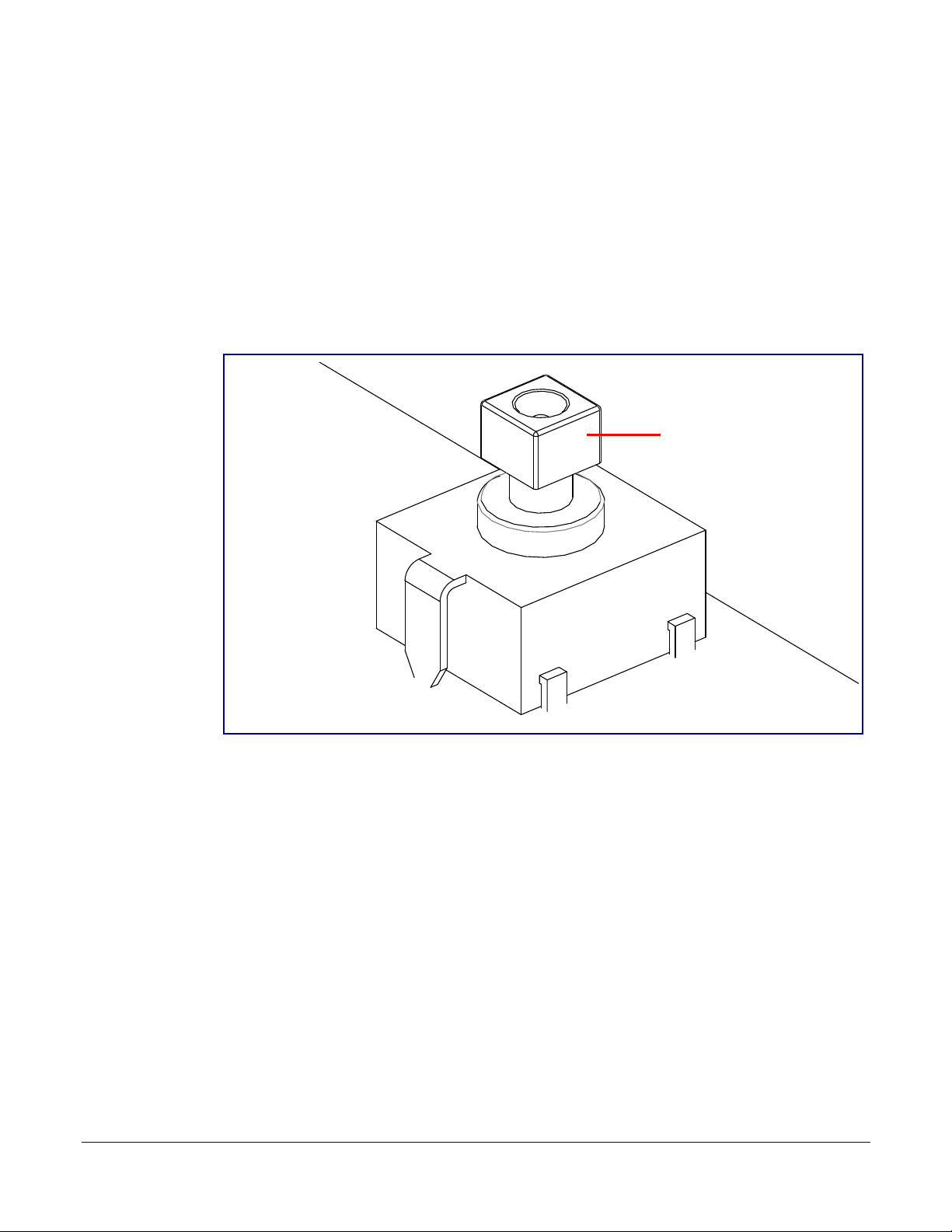
2.3.7.1 Announcing the IP Address
RTFM button (SW1)
To announce a device’s current IP address:
1. Press and release the RTFM button (see SW1 in Figure 2-16) within a five second window.
Note The device will use DHCP to obtain the new IP address (DHCP-assigned address or default
to 10.10.10.10 if a DHCP server is not present).
Note Pressing and holding the RTFM button for longer than five seconds will restore the device to
the factory default settings.
Installing the Singlewire InformaCast Indoor Intercom with Keypad
Figure 2-16. RTFM Button (SW1)
RTFM Button
24
Operations Guide 931640A CyberData Corporation
Page 32
Installing the Singlewire InformaCast Indoor Intercom with Keypad
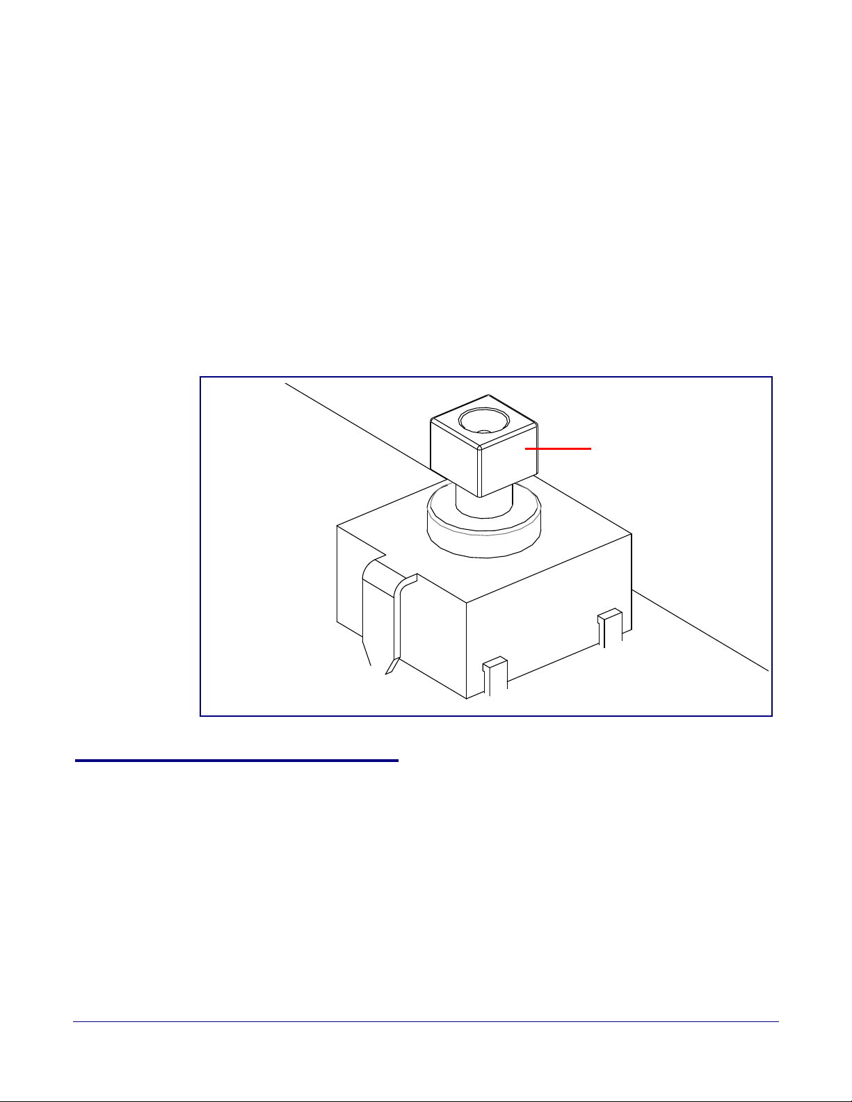
RTFM button (SW1)
2.3.7.2 Restoring the Factory Default Settings
When troubleshooting configuration problems, it is sometimes convenient to restore the device to a
known state.
Note Each Intercom is delivered with factory set default values.
To restore the factory default settings:
1. Press and hold the RTFM button (see SW1 in Figure 2-17) for more than five seconds.
2. The device announces that it is restoring the factory default settings.
Note The device will use DHCP to obtain the new IP address (DHCP-assigned address or default
to 10.10.10.10 if a DHCP server is not present).
Figure 2-17. RTFM Button (SW1)
Adjust the Volume
25
2.3.8 Adjust the Volume
You can adjust the volume through the Device Configuration Page.
Operations Guide 931640A CyberData Corporation
Page 33

Installing the Singlewire InformaCast Indoor Intercom with Keypad
2.4 Configure the Intercom Parameters
To configure the Intercom online, use a standard web browser.
Factory Default Settings
26
Configure each Intercom and verify its operation bef
an Intercom, refer to Appendix A, "Mounting the Singlewire InformaCast Indoor Intercom with
Keypad" for instructions.
2.4.1 Factory Default Settings
All Intercoms are initially configured with the following default IP settings:
When configuring more than one Intercom, attach the Intercoms to the network and configure one at
time to avoid IP address conflicts.
a
Parameter Factory Default Setting
IP Addressing DHCP
IP Address
Web Access Username admin
Web Access Password admin
Subnet Mask
Default Gateway
a
a
a
ore you mount it. When you are ready to mount
Table 2-5. Factory Default Settings
10.10.10.10
255.0.0.0
10.0.0.1
a. Default if there is not a DHCP server present.
Operations Guide 931640A CyberData Corporation
Page 34
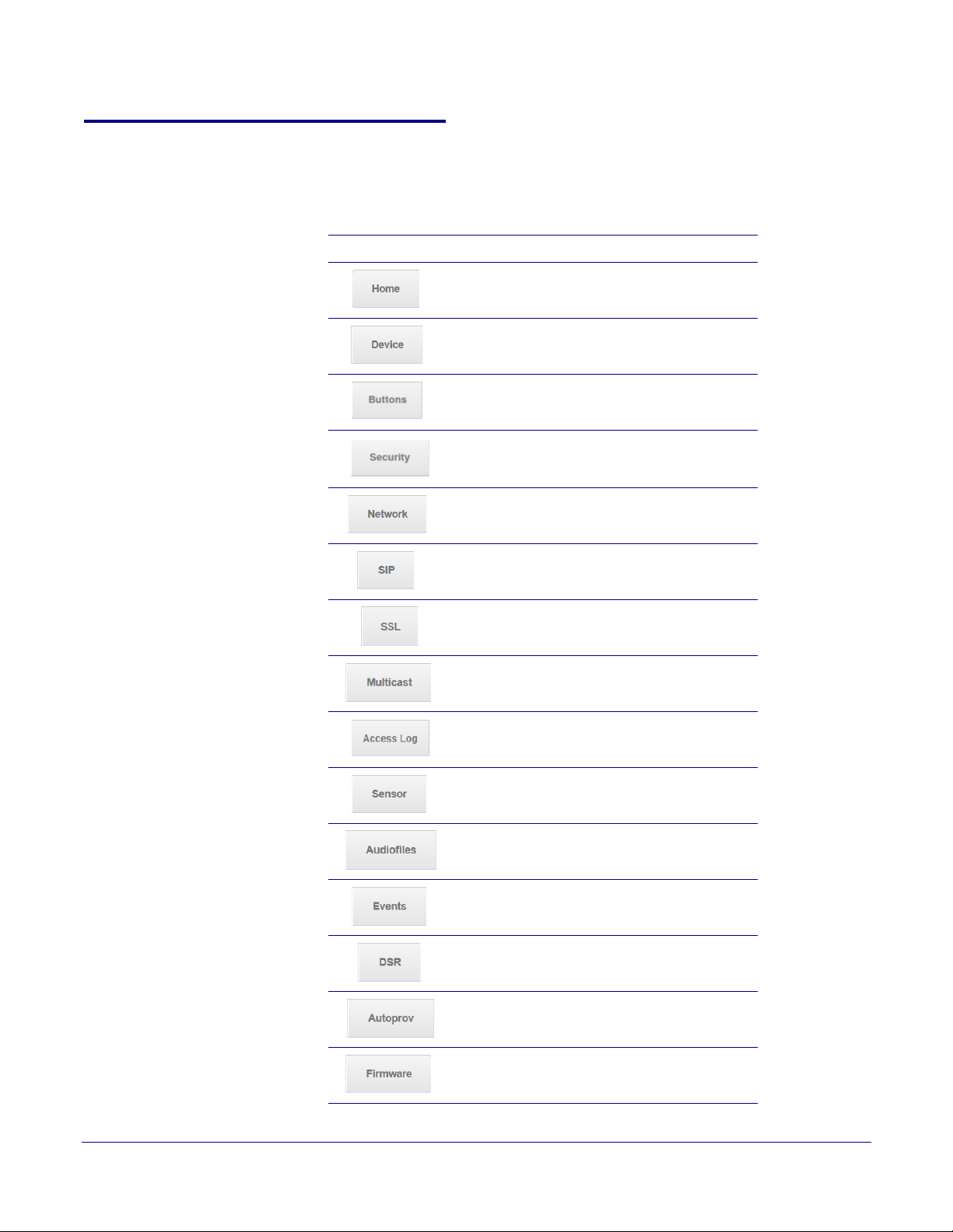
2.4.2 Intercom Web Page Navigation
Ta bl e 2-6 shows the navigation buttons that you will see on every Intercom web page.
Table 2-6. Web Page Navigation
Web Page Item Description
Installing the Singlewire InformaCast Indoor Intercom with Keypad
Intercom Web Page Navigation
Link to the Home page.
Link to the Device page.
27
Link to the Buttons
Link to the Security page
Link to the Netw
Link to go to the SIP page.
Link to the SSL page.
Link to the Multicast page.
Link to the Access Log page.
Link to the Sensor p
Link to the Audiofiles page.
page.
.
ork page.
age.
Link to the Events page.
Link to the Door Strike Relay page.
Link to the Autoprovisioning page.
Link to the Firmware page.
Operations Guide 931640A CyberData Corporation
Page 35
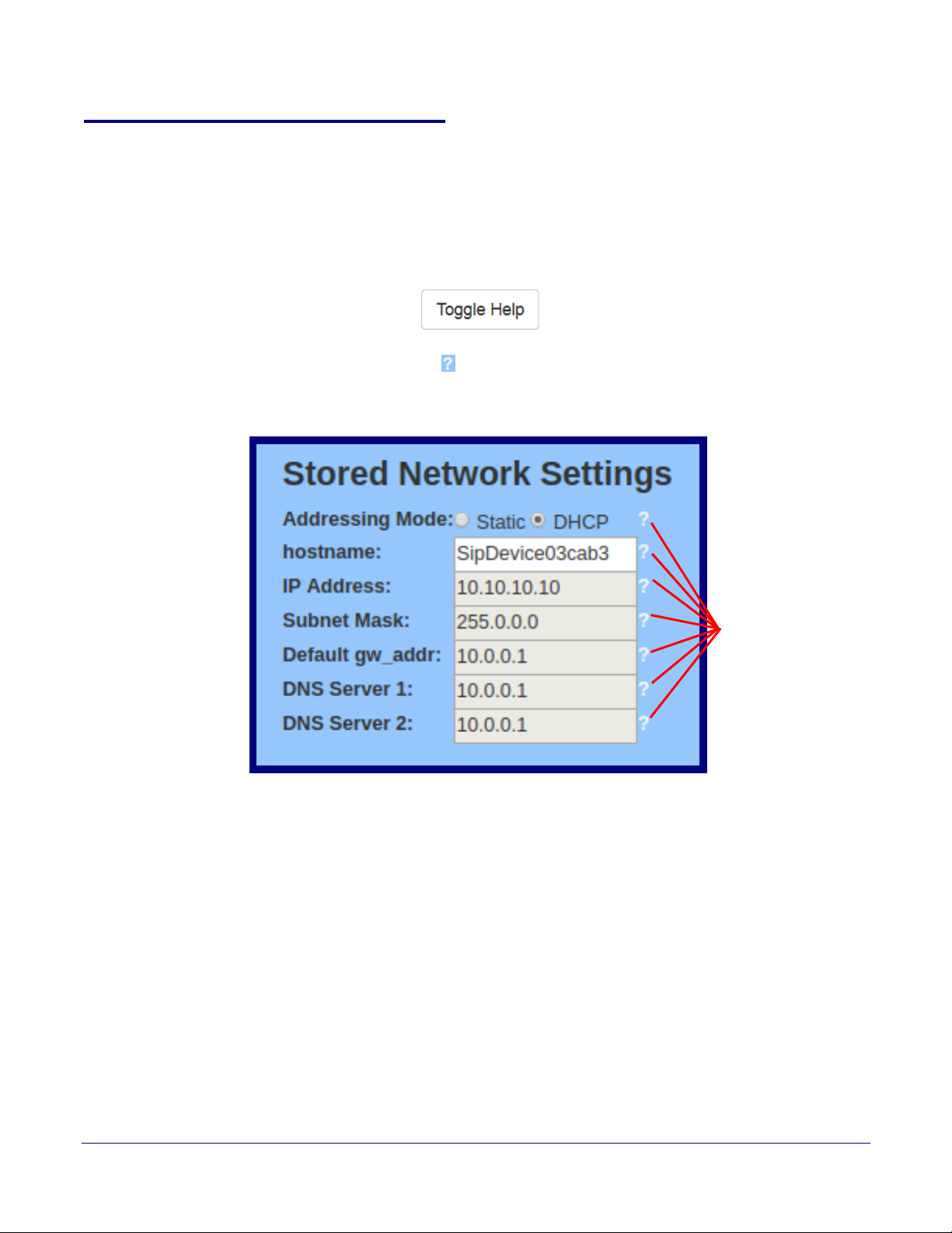
2.4.3 Using the Toggle Help Button
Question mark
appears next to the
web page items
The Toggle Help button allows you to see a short description of some of the settings on the
webpage. To use the Toggle Help button, do the following:
Installing the Singlewire InformaCast Indoor Intercom with Keypad
Using the Toggle Help Button
28
1. Click on the T
oggle Help button that is on the UI webpage. See Figure 2-18 and Figure 2-19.
Figure 2-18. Toggle/Help Button
2. You will see a question mark (
) appear next to each web page item that has been provided
with a short description by the Help feature. See Figure 2-19.
Figure 2-19. Toggle Help Button and Question Marks
Operations Guide 931640A CyberData Corporation
Page 36
Installing the Singlewire InformaCast Indoor Intercom with Keypad
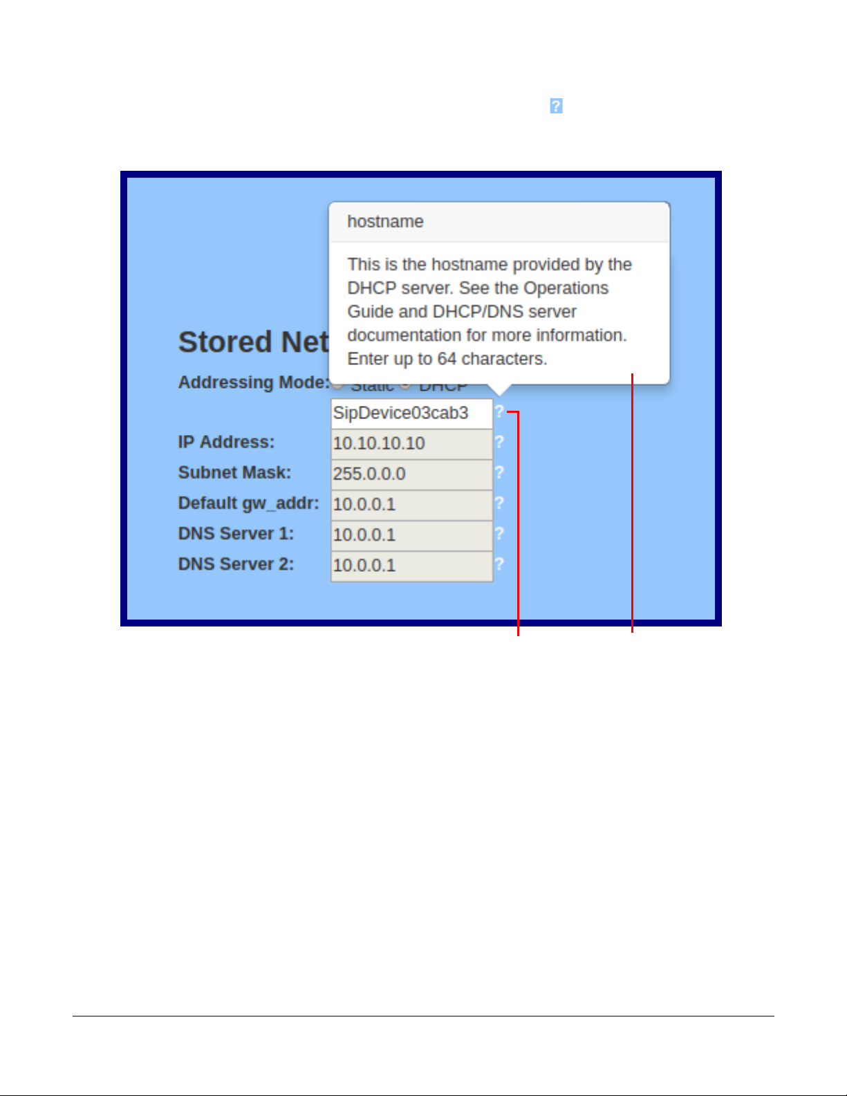
A short description of the
web page item will appear
Question mark
Hostname:
Using the Toggle Help Button
3. Move the mouse pointer to hover over the question mark ( ), and a short description of the web
page item will appear. See Figure 2-20.
Figure 2-20. Short Description Provided by the Help Feature
29
Operations Guide 931640A CyberData Corporation
Page 37

Installing the Singlewire InformaCast Indoor Intercom with Keypad
2.4.4 Log in to the Configuration Home Page
1. Open your browser to the Intercom IP address.
Note If the network does not have access to a DHCP server, the device will default to an IP
address of 10.10.10.10.
Note Make sure that the PC is on the same IP network as the Intercom.
Note You may also download CyberData’s VoIP Discovery Utility program which allows you to
easily find and configure the default web address of the CyberData VoIP products.
CyberData’s VoIP Discovery Utility program is available at the following website address:
https://www.cyberdata.net/pages/discovery
Note The Intercom ships in DHCP mode. To get to the Home page, use the discovery utility to
scan for the device on the network and open your browser from there.
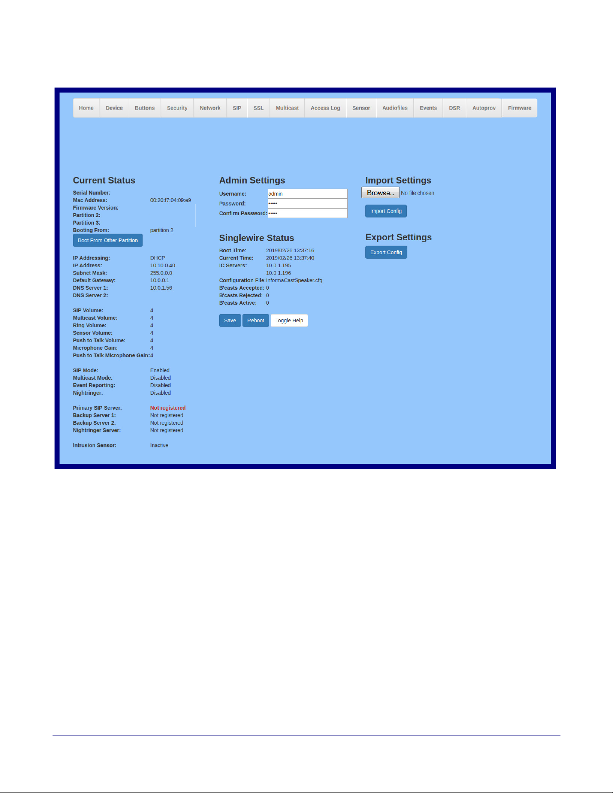
2. When prompted, use the following default Web Access Username and Web Access
Password to access the Home Page (
Web Access Username: admin
Web Access Password: admin
Figure 2-21):
Log in to the Configuration Home Page
30
Operations Guide 931640A CyberData Corporation
Page 38
Installing the Singlewire InformaCast Indoor Intercom with Keypad
v20.0.0
307200001
v20.0.0
v20.0.0
Singlewire Keypad Intercom
Figure 2-21. Home Page
Log in to the Configuration Home Page
31
Operations Guide 931640A CyberData Corporation
Page 39
Installing the Singlewire InformaCast Indoor Intercom with Keypad
Log in to the Configuration Home Page
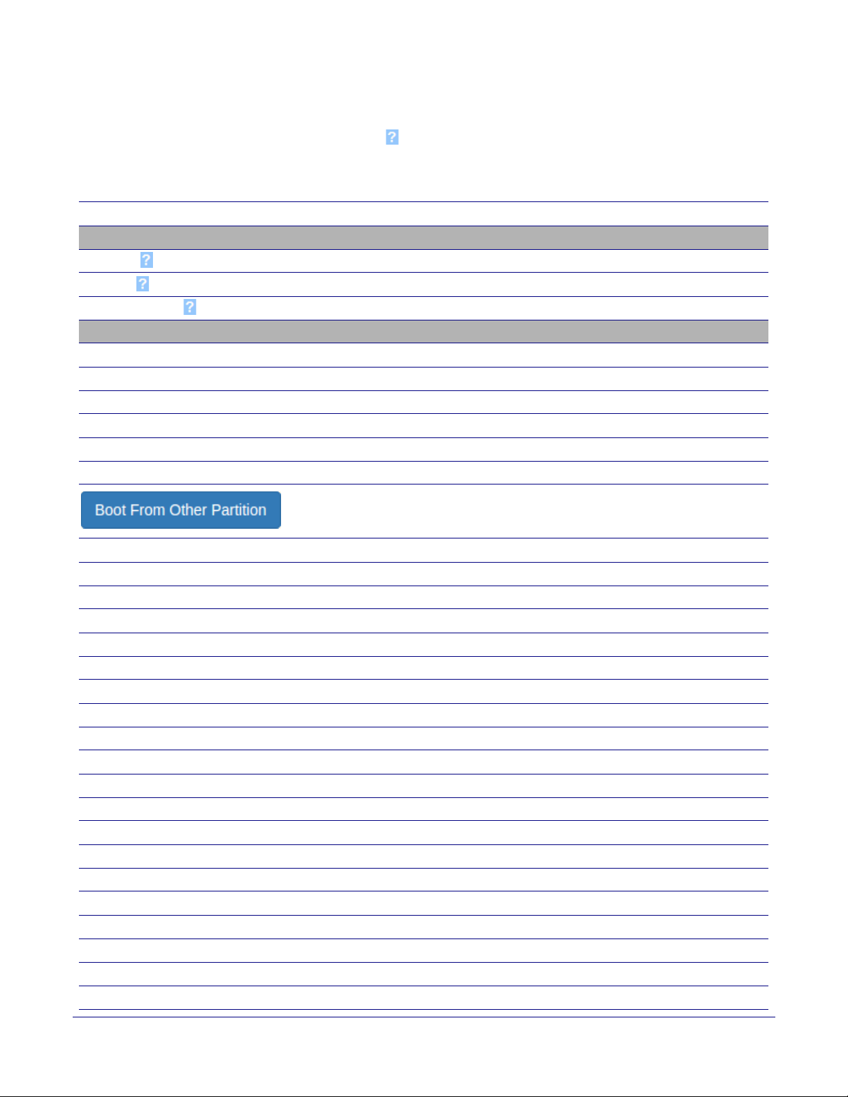
3. On the Home page, review the setup details and navigation buttons described in Ta bl e 2-7.
32
Note The question mark icon (
after the T
oggle Help button is pressed.
) in the following table shows which web page items will be defined
Table 2-7. Home Page Overview
Web Page Item Description
Admin Settings
Username The username to access the web interface. Enter up to 25 characters.
Password
Confirm Password
The password to access the web interface. Enter up to 25 characters.
Confirm the web interface password.
Current Status
Serial Number Shows the device serial number.
Mac Address Shows the device Mac address.
Firmware Version Shows the current firmware version.
Partition 2 Contains a complete copy of bootable software.
Partition 3 Contains an alternate, complete copy of bootable software.
Booting From Indicates the partition currently used for boot.
Allows the user to boot from the alternate partition.
IP Addressing Shows the current IP addressing setting (DH
CP or static).
IP Address Shows the current IP address.
Subnet Mask Shows the current subnet mask address.
Default Gateway Shows the current default gateway address.
DNS Server 1 Shows the current DNS Server 1 address.
DNS Server 2 Shows the current DNS Server 2 address.
SIP Volume Shows the current SIP volume level.
Multicast Volume Shows the current Multicast volume level.
Ring Volume Shows the current Ring volume level.
Sensor Volume Shows the current Sensor volume level.
Push to Talk Volume Shows the current push to talk volume
Microphone Gain Shows the current microphone gain level.
Push to Talk Microphone Gain Shows the current push to talk microphone gain level.
SIP Mode Shows the current status of the SIP mode.
Multicast Mode Shows the current status of the Multicast mode.
Event Reporting Shows the current status of the Event Reporting mode.
Nightringer Shows the current status of the Nightringer mode.
Primary SIP Server Shows the current status of the Primary SIP Server.
Backup Server 1 Shows the current status of Backup Server 1.
Backup Server 2 Shows the current status of Backup Server 2.
Operations Guide 931640A CyberData Corporation
Page 40
Installing the Singlewire InformaCast Indoor Intercom with Keypad
Table 2-7. Home Page Overview (continued)
Web Page Item Description
Nightringer Server Shows the current status of Nightringer Server.
Log in to the Configuration Home Page
33
Intrusion Sensor
Shows the current status of the intrusion sensor when the Home Page is refreshed.
Singlewire Settings
Boot Time Shows the boot time.
Current Time Shows the current time.
IC Servers Shows the InformaCast server IP addresses.
Configuration File Shows the configuration file.
B’casts Accepted Shows the number of B’casts
accepted.
B’casts Rejected Shows the number of B’casts rejected.
B’casts Active Shows the number of active B’casts.
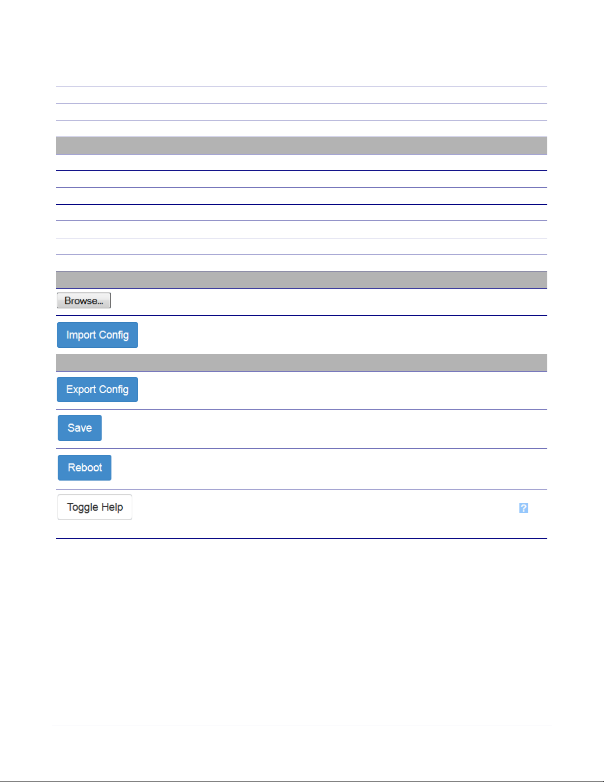
Import Settings
Use this button to select a configuration file to import.
After selecting a configuration file, click Import to import the configuration from the
selected file.
Export Settings
Click Export to export the current configuration to a file.
Click the Save button to save your configuration settings.
Click on the Reboot button to reboot the system.
Click on the Toggle Help button to see a short description of some of the web page
items. First click on the Toggle Help button, and you will see a question mark ( )
appear next to some of the web page items. Move the mouse pointer to hover over a
q
uestion mark to see a short description of a specific web page item.
Operations Guide 931640A CyberData Corporation
Page 41
2.4.5 Configure the Device
Singlewire Keypad Intercom
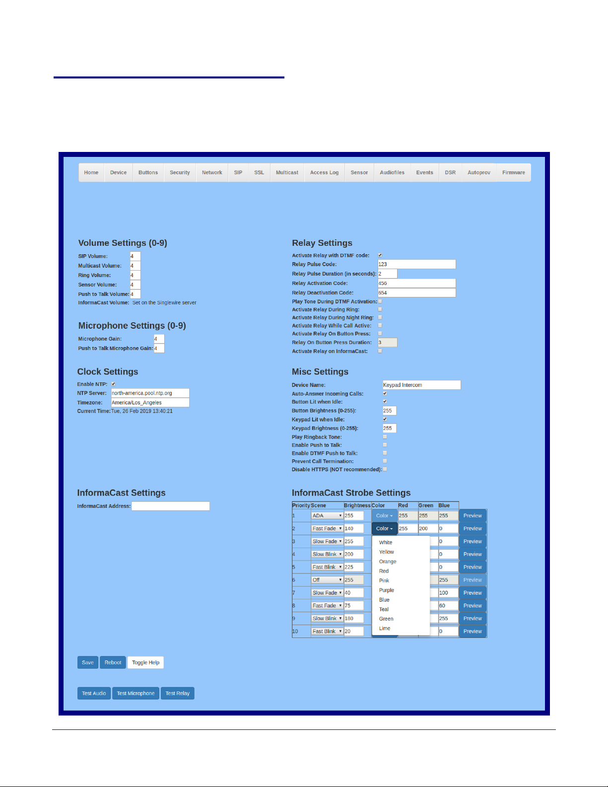
1. Click the Device menu button to open the Device page. See Figure 2-22.
Figure 2-22. Device Configuration Page
Installing the Singlewire InformaCast Indoor Intercom with Keypad
Configure the Device
34
Operations Guide 931640A CyberData Corporation
Page 42

Installing the Singlewire InformaCast Indoor Intercom with Keypad
Configure the Device
2. On the Device page, you may enter values for the parameters indicated in Tab l e 2-8.
35
Note The question mark icon (
after the To
ggle Help button is pressed.
) in the following table shows which web page items will be defined
Table 2-8. Device Configuration Parameters
Web Page Item Description
Volume Settings (0-9)
SIP Volume Set the speaker volume for a SIP call. A value of 0 will mute the speaker
during SIP calls.
Multicast Volume
Set the speaker volume for multicast audio streams. A value of 0 will mute
the speaker during multicasts.
Ring Volume
Set the ring volume for incoming calls. A value of 0 will mute the speaker
instead of playing the ring tone when Auto-Answer Incoming Calls is
disabled.
Sensor Volume
Set the speaker volume for playing sensor activated audio. A value of 0
will mute the speaker during sensor activated audio.
Push to Talk Volume
Set the speaker volume for Push to Talk operation. A value of 0 will mute
the speaker in Push to Talk mode.
InformaCast Volume
Set on the Singlewire server.
Microphone Settings
Microphone Gain Set the microphone gain level.
Push to Talk Microphone Gain
Set the microphone gain level for Push to Talk operation.
Clock Settings
Enable NTP Sync device's local time with the specified NTP Server.
NTP Server
Use this field to set the address (in IPv4 dotted decimal notation or as a
canonical name) for the NTP Server. This field can accept canonical
names of up to 64 characters in length.
Timezone Enter the tz database str
ing of your timezone.
Examples:
America/Los_Angeles
America/New_York
Europe/London
America/Toronto
See
https://en.wikipedia.org/wiki/List_of_tz_database_time_zones
for a full list of valid strings.
Current Time
Displays the current time.
InformaCast Settings
Operations Guide 931640A CyberData Corporation
Page 43

Installing the Singlewire InformaCast Indoor Intercom with Keypad
Configure the Device
Table 2-8. Device Configuration Parameters (continued)
Web Page Item Description
InformaCast Address Use this field to set the address of your InformaCast server. This will
override any InformaCast server addresses received via SLP or DHCP.
If using TFTP for configuration, simply enter an IP address (eg.
10.0.1.195) If using HTTP for configuration, enter the full URL to the path
that contains the configuration file.
Do not input the file name (e.g.http://10.0.1.195:8081/InformaCast/
resources/).If the HTTP protocol is not specified with http://, then TFTP
will be used.
Relay Settings
Activate Relay with DTMF Code Activates the relay when the DTMF Activation Code is entered on the
phone during a SIP call with the device. RFC2833 DTMF payload types
are supported.
Relay Pulse Code
DTMF code used to pulse the relay when entered on a phone during a
SIP call with the device. Relay will activate for Relay Pulse Duration
seconds then deactivate. Activate Relay with DTMF Code must be
enabled. Enter up to 25 digits (* and # are supported).
Relay Pulse Duration (in seconds) The length of time (in seconds) during which the relay will be activated
when the DTMF Relay Activation Code is detected. Enter up to 5 digits.
Relay Activation Code
Activation code used to activate the relay when entered on a phone during
a SIP call with the device. Relay will be active indefinitely, or until the
DTMF Relay Deactivation code is entered. Activate Relay with DTMF
Code must be enabled. Enter up to 25 digits (* and # are supported).
36
Relay Deactivation Code Code used to deactivate the relay when entered on a phone during a SIP
call with the device. Activate Relay with DTMF Code must be enabled.
Enter up to 25 digits (* and # are supported).
Play tone during DTMF Activation
When selected, the device will play a tone out of the speaker upon DTMF
relay activation. The tone plays for the DTMF Activation Duration (in
seconds).
Activate Relay During Ring
When selected, the relay will be activated for as long as the device is
ringing. When Auto-Answer Incoming Calls is enabled, the device will not
ring and this option does nothing.
Activate Relay During Night Ring
When selected, the relay will be activated as long as the Nightringer
extension is ringing.
Activate Relay While Call Active
Activate Relay on Button Press
Relay on Button Press Duration
When selected, the relay will be activated as long as the SIP call is active.
When selected, the relay will be activated when the Call button is pressed.
The length of time (in seconds) during which the relay will be activated
when the Call button is pressed. Enter up to 5 digits. A Relay on Button
Press Duration value of 0 will pulse the relay once when the Call button
is pressed.
Activate Relay on InformaCast
Check this box to activate the relay while receiving a page from
Informacast. The relay will activate on a start command and deactivate on
a stop command.
Misc Settings
Device Name Type the device name. Enter up to 25 characters.
Operations Guide 931640A CyberData Corporation
Page 44

Installing the Singlewire InformaCast Indoor Intercom with Keypad
Configure the Device
Table 2-8. Device Configuration Parameters (continued)
Web Page Item Description
Auto-Answer Incoming Calls When selected, the device will automatically answer incoming calls. When
Auto-Answer Incoming Calls is disabled, the device will play a ring tone
(corresponds to Ring Tone on the Audiofiles page) out of the speaker until
someone presses the Call button to answer the call or the caller
disconnects before the call can be answered.
Button Lit When Idle
When selected, the Call button LED is illuminated while the device is idle
(a call is not in progress).
Button Brightness (0-255)
The desired Call button LED brightness level. Acceptable values are 0255, where 0 is the dimmest and 255 is the brightest. Enter up to three
digits.
Keypad Lit When Idle
When selected, the keypad is illuminated while the device is idle (a call is
not in progress).
37
Keypad Brightness (0-255)
The desired keypad brightness level. Acceptable values are 0-255, where
0 is the dimmest and 255 is the brightest. Enter up to three digits.
Play Ringback Tone
When selected, the device will play a ringback tone (corresponds to
Ringback Tone on the Audiofiles page) out of the speaker while placing an
outbound call. The Ringback Tone will play until the call is answered.
Enable Push to Talk
This option is for noisy environments. When enabled, the microphone will
be muted normally. When the Call button is pressed and held, it will
unmute the microphone and allow the operator to send audio back. Using
Push to Talk prevents the operator from terminating a call by pressing the
Call button. The call must be terminated by the phone user.
Enable DTMF Push to Talk
This option is for noisy environments. When enabled, in an active call, the
remote phone can force receive only audio (setting the mic gain to max
and muting the speaker) by pressing the * key.
Pressing the # key will force send only audio (setting the max speaker
volume and muting the mic). Pressing the 0 key will restore full duplex
operation with the normal microphone and speaker volume.
Prevent Call Termination
When this option is enabled, a call cannot be terminated using the call
button.
Disable HTTPS (NOT recommended)
Disables the encrypted connection to the webpage. We do not
recommend disabling HTTPS for security reasons.
Note This setting requires a reboot for the changes to take effect.
Singlewire Broadcast Strobe Settings For up to 10 Singlewire pages, when a priority is specified for the page, a
corresponding strobe scene will be activated. The color may be selected
from the drop down menu, or customized by the user with the 0-255 scale.
Brightness is specified with a value between 0 and 255.
The following strobe settings will only appear if a CyberData Strobe
oduct is connected to your device. If a CyberData Strobe product
pr
is not connected to your device, you will not see the strobe settings.
Priority
Indicates the priority of the Singlewire broadcast, with 1 the highest
priority and 10 the lowest.
Scene
Use this section to select the strobe flashing behavior for the Singlewire
Broadcast.
ADA Compliant
Strobe will blink ON at the specified brightness for 150ms then OFF for
350ms during the duration of the event.
Operations Guide 931640A CyberData Corporation
Page 45
Installing the Singlewire InformaCast Indoor Intercom with Keypad
Configure the Device
Table 2-8. Device Configuration Parameters (continued)
Web Page Item Description
Slow Fade Strobe will increase in brightness from 0 to the specified brightness and
back to 0 over the course of about 3.5 seconds during the duration of the
event.
Fast Fa de Strobe will increase in brightness from 0 to the specified brightness and
back to 0 over the course of about 1.5 seconds during the duration of the
event.
38
Slow Blink
Fast Blink
Color
Brightness
Red
Green
Blue
Strobe will blink ON at the specified brightness for one second then OFF
for one second during the duration of the event.
Strobe will blink ON at the specified brightness then OFF five times per
second during the duration of the event.
Select the desired color (only one may be chosen).
How bright the strobe will blink when there is a Singlewire Broadcast. This
is the maximum brightness for “fade” type scenes.
The red LED value for the Singlewire Broadcast.
The green LED value for the Singlewire Broadcast.
The blue LED value for the Singlewire Broadcast.
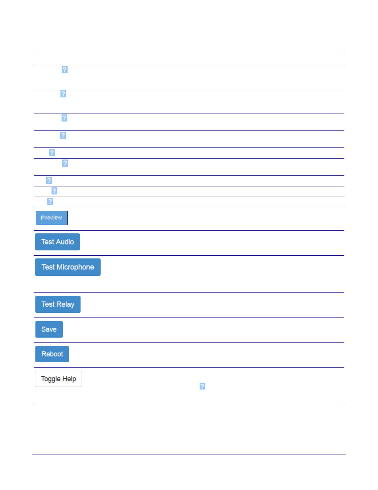
Use this button to preview the strobe flashing behavior for the Sensor
Strobe Settings.
Click on the Test Audio button to do an audio test. When the Test Audio
button is pressed, you will hear a voice message for testing the device
audio quality and volume.
Click on the Test Microphone button to do a microphone test. When the
Test Microphone button is pressed, the following occurs:
1. The device will immediately start recording 3 seconds of audio.
2. The device will play back the recorded audio.
Click on the Test Relay button to do a relay test.
Click the Save button to save your configuration settings.
Click on the Reboot button to reboot the system.
Click on the Toggle Help button to see a short description of some of the
web page items. First click on the Toggle Help button, and you will see a
question mark (
) appear next to some of the web page items. Move the
mouse pointer to hover over a question mark to see a short description of
a specific web page item.
Operations Guide 931640A CyberData Corporation
Page 46
Installing the Singlewire InformaCast Indoor Intercom with Keypad
Singlewire Keypad Intercom
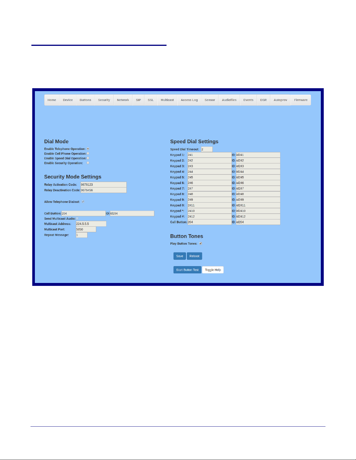
2.4.6 Configure the Button Parameters
1. Click the Button Config button to open the Button Configuration page. See Figure 2-23.
Figure 2-23. Button Configuration Page
Configure the Button Parameters
39
Operations Guide 931640A CyberData Corporation
Page 47

Installing the Singlewire InformaCast Indoor Intercom with Keypad
Configure the Button Parameters
2. On the Button Configuration page, you may enter values for the parameters indicated in
Ta bl e 2-9.
Table 2-9. Button Configuration Parameters
40
Web Page Item
Description
Dial Mode
Enable Telephone Operation Dial extensions like a normal telephone. Pressing the call button will start a dial tone.
Pressing the call button in a call will cancel a call.
Enable Cellphone Operation
Enter your extension and press the call button to start the call. Press the call button again
to cancel the call.
Enable Speed Dial Operation
In speed dial mode every button can be configured to call a different extension when
pressed.
Enable Security Operation
Security mode allows the user to secure the local or remote relay by requiring a code (up
to 8 digits) to be entered into the device's keypad. The security codes may be entered
within a phone call to a preset extension or independently. Security codes start with the
pound key (#) and will be recognized when the user stops pressing buttons or hits the
pound key again.
Security Mode Settings
Relay Activation Code Activation code used to activate the relay when entered on a phone during a SIP call with
the device. Relay will be active indefinitely, or until the DTMF Relay Deactivation code is
entered. Enter up to 25 digits (* and # are supported).
Relay Deactivation Code
Code used to deactivate the relay when entered on a phone during a SIP call with the
device. Enter up to 25 digits (* and # are supported).
Allow Telephone Dialout
When enabled, the user will be able to use the keypad to dial while the device is in
Security mode.
Call Button
ID
Send Multicast Audio
Dial this extension when the call button is pressed. Up to 64 characters.
Type the desired Extension ID. Up to 64 characters.
When selected, the device will play an audio file to the specified multicast address and
port.
Note: The keypad must be in Security mode to send Multicast Audio.
Multicast Address
Multicast Port
Repeat Message
The multicast address used for multicasting an audio file.
The multicast port used for multicasting an audio file.
The number of times to repeat the audio message to the remote endpoint. Enter a value
from 1-65536.
Speed Dial Settings
Speed Dial Timeout The amount of time you must hold the button before it calls the configured extension.
When this is set to 0 the phone will dial the configured extension as soon as the button is
released.
Keypad 1 Dial this extension when the 1 key is pressed.
Keypad 2 Dial this extension when the 2 key is pressed.
Keypad 3 Dial this extension when the 3 key is pressed.
Keypad 4 Dial this extension when the 4 key is pressed.
Keypad 5 Dial this extension when the 5 key is pressed.
Keypad 6 Dial this extension when the 6 key is pressed.
Keypad 7 Dial this extension when the 7 key is pressed.
Operations Guide 931640A CyberData Corporation
Page 48
Installing the Singlewire InformaCast Indoor Intercom with Keypad
Table 2-9. Button Configuration Parameters (continued)
Web Page Item Description
Keypad 8 Dial this extension when the 8 key is pressed.
Keypad 9 Dial this extension when the 9 key is pressed.
Keypad 0 Dial this extension when the 0 key is pressed.
Keypad * Dial this extension when the * key is pressed.
Keypad # Dial this extension when the # key is pressed.
Call Button
Button Tones
Play Button Tones Play a tone when the keypad buttons are pressed.
Dial this extension when the call button is pressed.
Click the Save button to save your configuration settings.
Click on the Reboot button to reboot the system.
Click on the Start button to start a button test.
Configure the Button Parameters
41
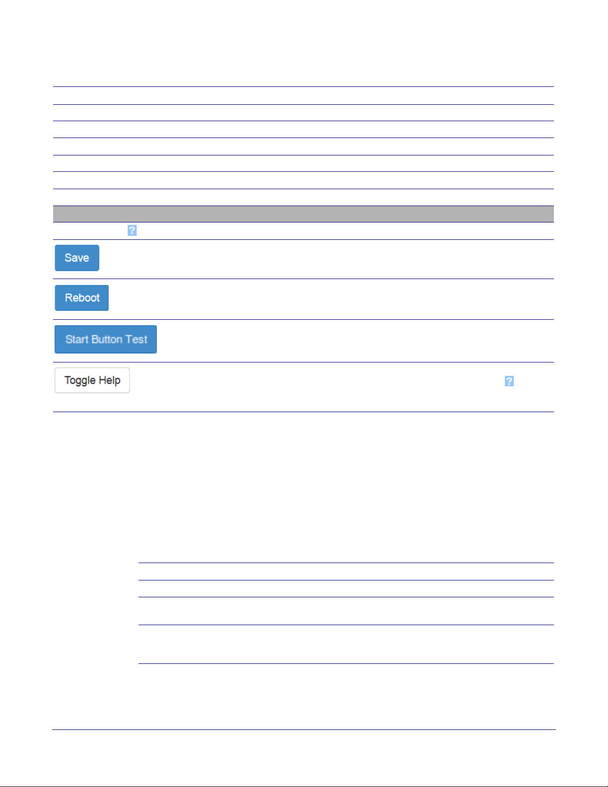
Click on the Toggle Help button to see a short description of some of the web page
items. First click on the Toggle Help button, and you will see a question mark (
next to some of the web page items. Move the mouse pointer to hover over a question
mark to see a short description of a specific web page item.
Note While in Security Mode, the 011375 Network Dual Door Strike Relay will operate only in
Automatic Mode.
2.4.6.1 Dial Out Extension Strings and DTMF Tones (using rfc2833)
On the Button Configuration page, dial out extensions support the addition of comma delimited
pauses and sending additional DTMF tones (using rfc2833). The first comma will pause three
seconds after a call is first established with a remote device. Subsequent commas will pause for 2
seconds. A pause of one second will be sent after each numerical digit.
Table 2-10. Examples of Dial-Out Extension Strings
Extension String Resulting Action
302 Dial out extension 302 and establish a call
302,2 Dial out extension 302 and establish a call, wait 3 seconds then send the
DTMF tone '2'
302,25,,,4,,1 Dial out extension 302 and establish a call, wait 3 seconds then send the
DTMF tone '2', send out DTMF tone 5, wait 6 seconds, send out DTMF
tone 4, wait 4 seconds, send out DTMF tone 1
) appear
Note The ma
Operations Guide 931640A CyberData Corporation
ximum number of total characters in the dial-out field is 25.
Page 49

Installing the Singlewire InformaCast Indoor Intercom with Keypad
2.4.6.2 Triggering a Dial Out Call or Security Code
You can instantly trigger a dial out call or security code by pressing the # key after dialing a number.
Ta bl e 2-11 shows the various actions that result from different keypad input.
Table 2-11. Triggering a Dial Out Call or Security Code
Allow Telephone Dialout Option Enabled (in security mode with default security settings)
Input Resulting Action
Configure the Button Parameters
42
Dialing 123
(and waiting for several seconds)
Dialing #123
(and waiting for several seconds)
Dialing #1234560
(and waiting for several seconds)
Dialing #124560# The device will instantly activate the relay for 6 seconds.
Dialing 123#
The device will call extension 123 through the default SIP server.
The device will do nothing. The entry is an unrecognized security
entry.
The device will activate the relay for Security Code 0 for 6 seconds.
The device will instantly call extension 123 through the default SIP
server.
Allow Telephone Dialout Option Disabled (in security mode with default security settings)
Input Resulting Action
Dialing 123
(and waiting several seconds)
Dialing 9876123
(and waiting several seconds)
Dialing 9876456
(and waiting several seconds)
456
The device will activate the relay specified on the Security
Configuration Page (local or DSR) for the seconds specified in the
Relay Timeout (seconds) setting.
The device will activate the local relay.
The device will deactivate the local relay.
Operations Guide 931640A CyberData Corporation
Page 50
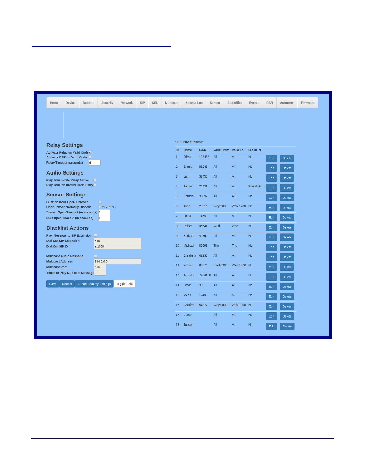
2.4.7 Configure the Security
Singlewire Keypad Intercom
1. Click the Security menu button to open the Security page. See Figure 2-22.
Figure 2-24. Security Configuration Page
Installing the Singlewire InformaCast Indoor Intercom with Keypad
Configure the Security
43
Operations Guide 931640A CyberData Corporation
Page 51
Installing the Singlewire InformaCast Indoor Intercom with Keypad
Configure the Security
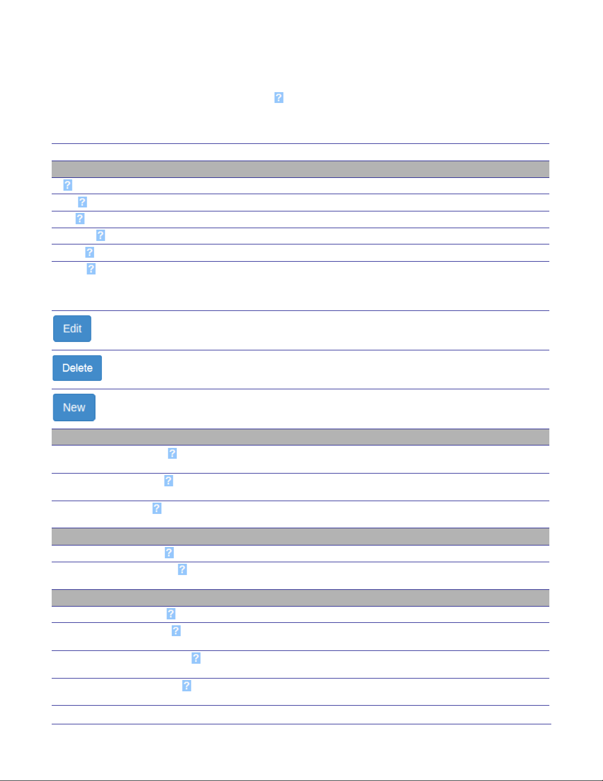
2. On the Security page, you may enter values for the parameters indicated in Ta bl e 2-12.
44
Note The question mark icon (
after the To
ggle Help button is pressed.
) in the following table shows which web page items will be defined
Table 2-12. Security Configuration Parameters
Web Page Item Description
Security Settings
ID Displays the ID associated with this security record.
Name
Code
Val i d Fro m
Val i d To
Blacklist
Displays the name associated with this security record.
Displays the security code associated with this security record.
See Section 2.4.7.2, "The “Valid From” and “Valid To” Settings".
See Section 2.4.7.2, "The “Valid From” and “Valid To” Settings".
Displays the Blacklisted status of this security record. Blacklist is used to deny
entry to the specified security code. Entering a blacklisted code will trigger the
buzzer, and can trigger a call to an extension or a multicast of a pre-recorded
message.
Opens the Configure Security Code Page. See Section 2.4.7.1, "Configure
the Security Code Page".
Removes the security code record.
Opens a new Configure Security Code window.
Relay Settings
Activate Relay on Valid Code Activates the relay when a valid code is entered. This would likely be used to
open a door.
Activate DSR on Valid Code
Activates the remote relay when a valid code is entered. This would likely be
used to open a door.
Relay Timeout (seconds)
Specifies how many seconds the relay will be activated after a valid code
entry. In a typical use case, this would specify how long the door is unlocked.
Audio Settings
Play tone while Relay Active When selected, an audible tone will indicate the relay is active.
Play tone on Invalid Code Entry
When selected, a tone will play on the speaker to indicate an invalid code was
entered.
Sensor Settings
Buzz on Door Open Timeout When selected, the buzzer will beep until the on board sensor is deactivated.
Door Sensor Normally Closed
Select the inactive state of the door sensor. The door sensor is also known as
the Sense Input on the device's terminal block.
Sensor Open Timeout (in seconds)
The time (in seconds) the device will wait before it triggers the buzzer when
the door sensor is active.
DSR Open Timeout (in seconds)
The time (in seconds) the device will wait before it triggers the buzzer when
the remote door sensor (DSR) is active.
Operations Guide 931640A CyberData Corporation
Page 52
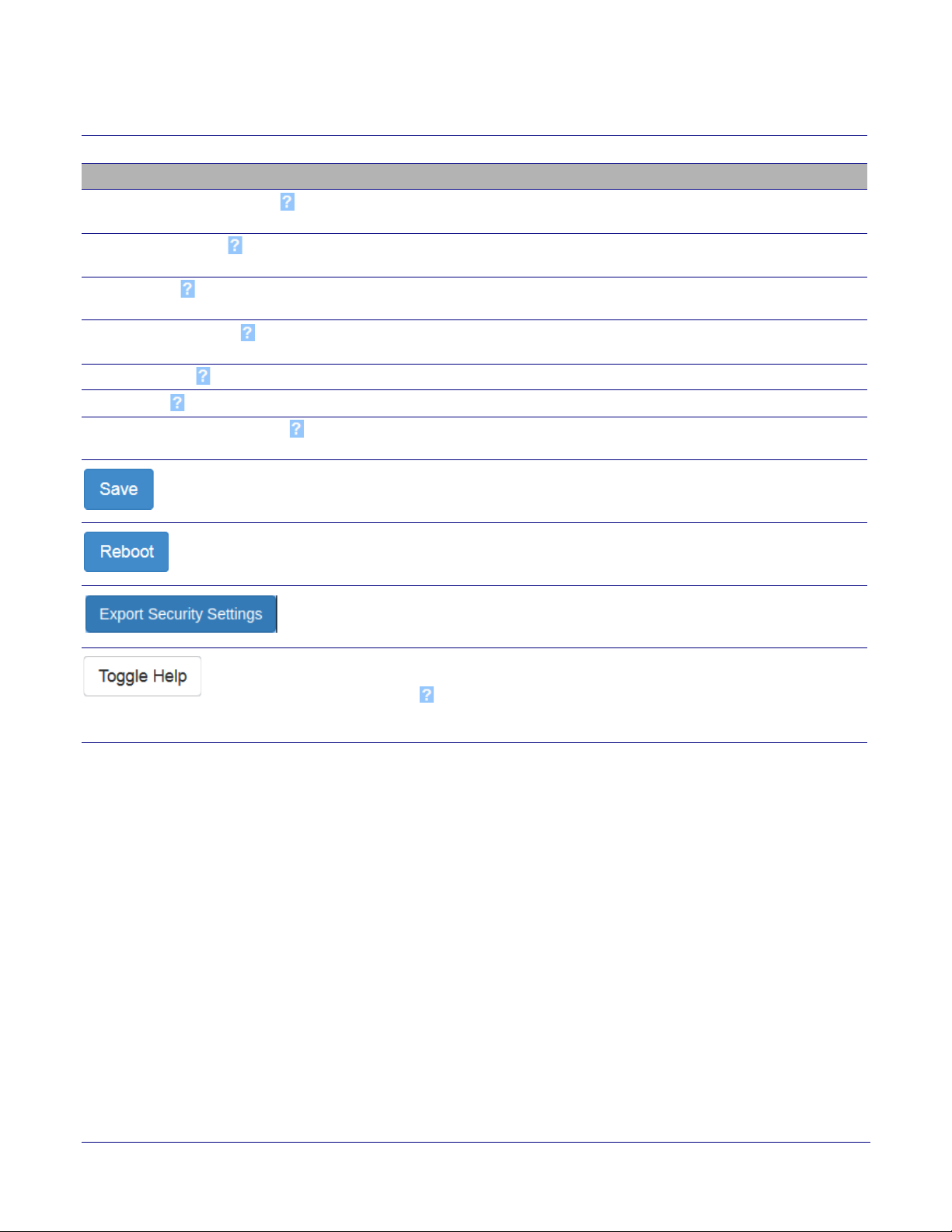
Installing the Singlewire InformaCast Indoor Intercom with Keypad
Configure the Security
Table 2-12. Security Configuration Parameters (continued)
Web Page Item Description
Blacklist Actions
Play Message to SIP Extension When selected, the device will make a SIP call and play the “blacklist” audio
file when a blacklisted code is entered.
45
Dial Out SIP Extension
Dial Out SIP ID
Multicast Audio Message
Multicast Address
Multicast Port
Times to Play Multicast Message
The extension that will be dialed if “Play Mesage to SIP Extension” is selected
above. Enter up to 64 alphanumeric characters.
Additional caller identification string added to outbound calls. Enter up to 64
alphanumeric characters.
When selected, the device will multicast the “blacklist” audio file to the
specified address and port.
The multicast address that the “blacklist” audiofile will be played to.
The multicast port that the “blacklist” audofile will be played to.
The number of times the “blacklist” audio file will be played via multicast. Enter
a value between 1 and 65535.
Click the Save button to save your configuration settings.
Click on the Reboot button to reboot the system.
Click on the Export Security Settings button to export the current security list
to a file.
Click on the Toggle Help button to see a short description of some of the web
page items. First click on the Toggle Help button, and you will see a question
mark (
pointer to hover over a question mark to see a short description of a specific
web page item.
) appear next to some of the web page items. Move the mouse
Note While in Security Mode, the 011375 Network Dual Door Strike Relay will operate only in
Automatic Mode.
2.4.7.1 Configure the Security Code Page
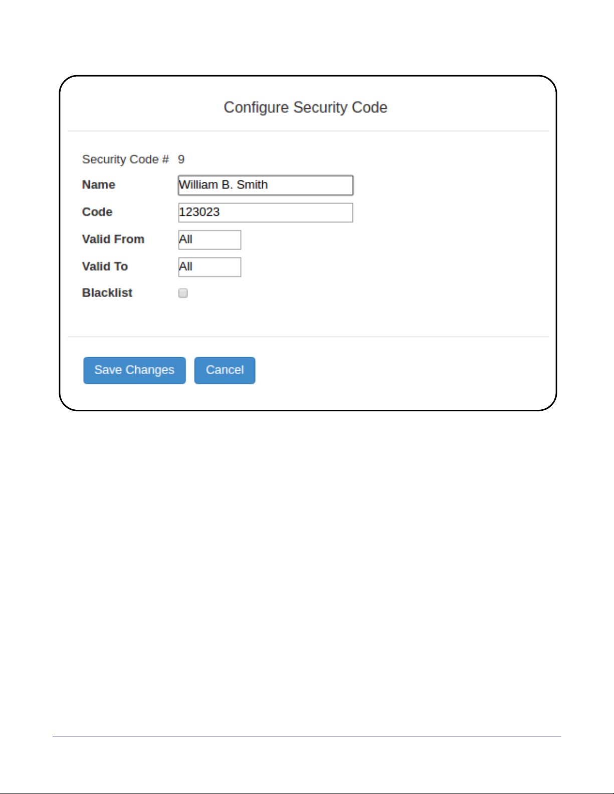
1. Click the Edit button to open the Configure Security Code page. See Figure 2-25.
Figure 2-25. Configure Security Code Page
Operations Guide 931640A CyberData Corporation
Page 53
Installing the Singlewire InformaCast Indoor Intercom with Keypad
Configure the Security
46
Operations Guide 931640A CyberData Corporation
Page 54
Installing the Singlewire InformaCast Indoor Intercom with Keypad
Configure the Security
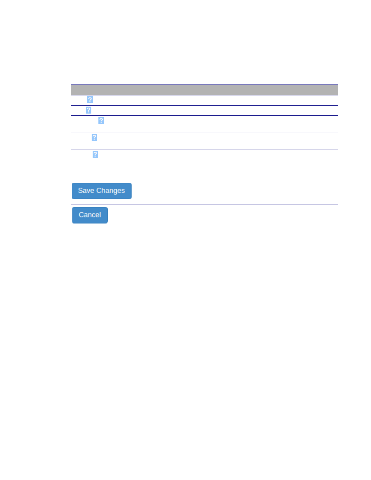
2. On the Configure Security Code page, you may enter values for the parameters indicated in
Ta bl e 2-12.
Table 2-13. Security Code Page Parameters
47
Web Page Item
Description
Security Configuration
Name Enter name.
Code
Val i d Fro m
Enter a security code, maximum 8 digits, must be distinct.
See Section 2.4.7.2, "The “Valid From” and “Valid To”
Settings".
Val i d To
See Section 2.4.7.2, "The “Valid From” and “Valid To”
Settings".
Blacklist
Blacklist is used to deny entry to the specified security
code. Entering a blacklisted code will trigger the buzzer,
and can trigger a call to an extension or a multicast of a
pre-recorded message.
Saves the changes of the security configuration.
Cancels the changes of the security configuration.
Operations Guide 931640A CyberData Corporation
Page 55

Installing the Singlewire InformaCast Indoor Intercom with Keypad
2.4.7.2 The “Valid From” and “Valid To” Settings
ValidFrom and ValidTo fields specify the day(s) a security code is valid, and, optionally the time, in
24:00 format.
The Day of the week can be Mon, Tue, Wed, Thu, Fri, Sat, Sun, or one of the special identifiers: All,
Wnd, and Wdy.
Wdy indicates weekdays (Monday-Friday).
Wnd indicates weekends (Saturday-Sunday).
All allows entrance at all times.
A valid string consists of a day of the week or a special identifier, plus an optional time, except if
using All, which will not use a time.
Some examples:
<ValidFrom0>Mon9:00</ValidFrom0>
<ValidTo0>Fri17:00</ValidTo0> monday through friday 9am to 5pm
<ValidFrom0>All</ValidFrom0>
Configure the Security
48
<ValidTo0>All</ValidTo0> all day every day
<ValidFrom0>All</ValidFrom0>
<ValidTo0>All12:00</ValidTo0> every day till 12:00
<ValidFrom0>Mon12:00</ValidFrom0>
<ValidTo0>Mon12:00</ValidTo0> times are inclusive - this code is only valid on monday at 12:00
<ValidFrom0>Wdy9:00</ValidFrom0>
<ValidTo0>Wdy17:00</ValidTo0> Weekdays from 9am to 5pm
Note The identifiers in to and from must match (for example, named day/named day,
Wdy/Wdy, Wnd/Wnd, All/All).
Note The device must set time with an NTP Server (see the Device Configuration Page). If an
NTP server is not used, all Valid From and Valid To fields must be set to All.
Operations Guide 931640A CyberData Corporation
Page 56
Installing the Singlewire InformaCast Indoor Intercom with Keypad
Singlewire Keypad Intercom
2.4.8 Configure the Network Parameters
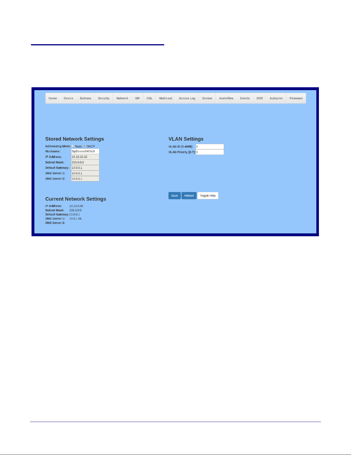
1. Click the Network menu button to open the Network page (Figure 2-26).
Figure 2-26. Network Configuration Page
Configure the Network Parameters
49
Operations Guide 931640A CyberData Corporation
Page 57
Installing the Singlewire InformaCast Indoor Intercom with Keypad
Configure the Network Parameters
2. On the Network page, enter values for the parameters indicated in Ta bl e 2-14.
50
Note The question mark icon (
after the To
ggle Help button is pressed.
) in the following table shows which web page items will be defined
Table 2-14. Network Configuration Parameters
Web Page Item Description
Stored Network Settings
Addressing Mode Select either DHCP IP Addressing or Static Addressing by marking the appropriate radio
button. DHCP Addressing mode is enabled on default and the device will attempt to
resolve network addressing with the local DHCP server upon boot. If DHCP Addressing
fails, the device will revert to the last known IP address or the factory default address if no
prior DHCP lease was established. See Section 2.4.1, "Factory Default Settings" for
factory default settings. Be sure to click Save and Reboot to store changes when
configuring a Static address.
Hostname This is the hostname provided by the DHCP server. See the DHCP/DNS server
documentation for more information. Enter up to 64 characters.
IP Address Enter the Static IPv4 network address in dotted decimal notation.
Subnet Mask Enter the Subnet Mask in dotted decimal notation.
Default Gateway Enter the Default Gateway IPv4 address in dotted decimal notation.
DNS Server 1 Enter the primary DNS Server IPv4 address in dotted decimal notation.
DNS Server 2 Enter the secondary DNS Server IPv4 address in dotted decimal notation.
Current Network Settings Shows the current network settings.
IP Address Shows the current Static IP address.
Subnet Mask Shows the current Subnet Mask address.
Default Gateway Shows the current Default Gateway address.
DNS Server 1 Shows the current DNS Server 1 address.
DNS Server 2 Shows the current DNS Server 2 address.
VLAN Settings
VLAN ID (0-4095) Specify the IEEE 802.1Q VLAN ID number. Enter up to 4 digits. A value of 0 disables
vlan.
Note: The device supports 802.1Q VLAN tagging support. The switch port connected to
the device will need to be in “trunking mode” for the VLAN tags to propagate.
VLAN Priority (0-7) Specify the IEEE 802.1p VLAN priority level. Enter 1 digit. A value of 0 may cause the
VLAN ID tag to be ignored.
Click the Save button to save your configuration settings.
Click on the Reboot button to reboot the system.
Click on the Toggle Help button to see a short description of some of the web page
items. First click on the Toggle Help button, and you will see a question mark ( ) appear
next to some of the web page items. Move the mouse pointer to hover over a question
mark to see a short description of a specific web page item.
Operations Guide 931640A CyberData Corporation
Page 58
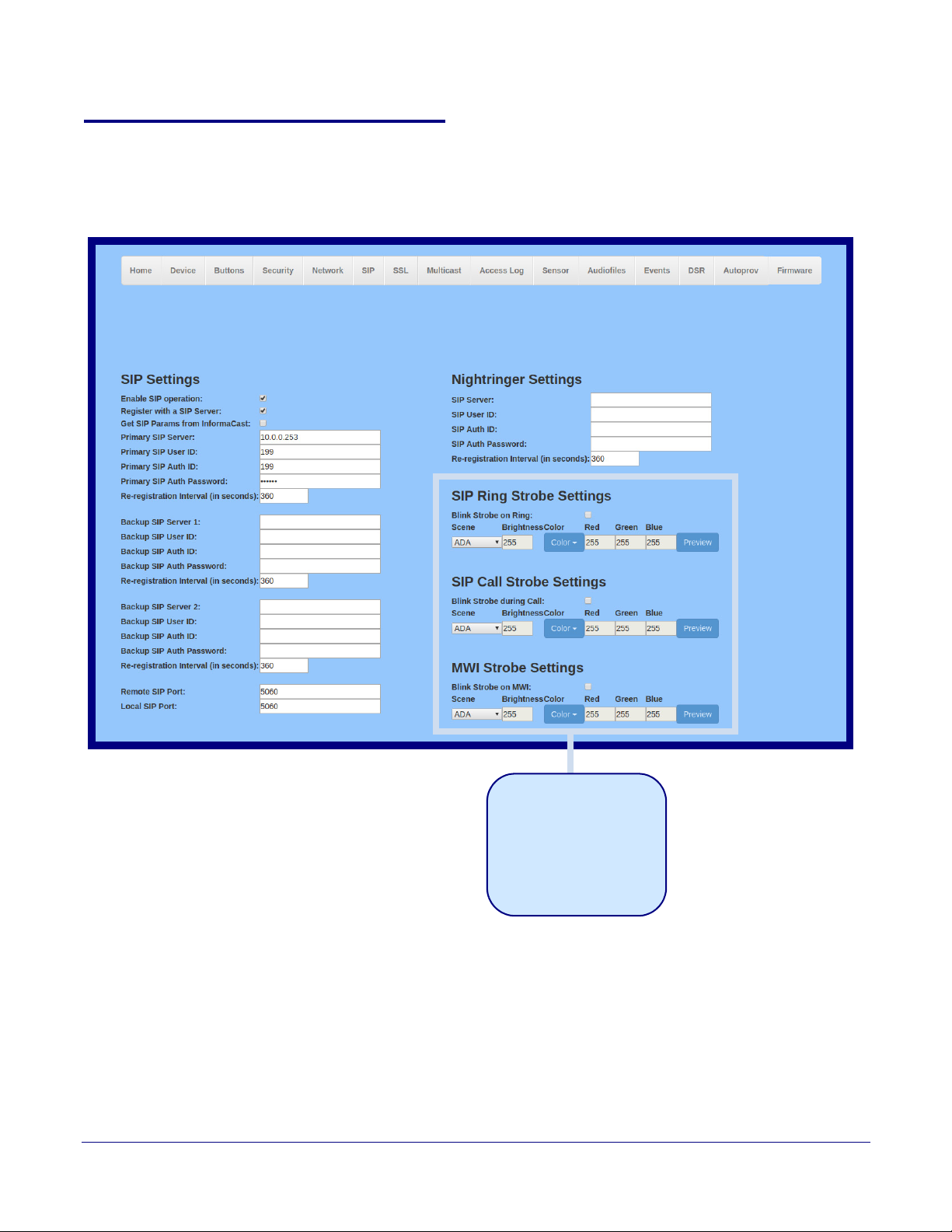
Installing the Singlewire InformaCast Indoor Intercom with Keypad
The strobe settings will only
appear if a CyberData Strobe
product is connected to your
device.
If a CyberData Strobe product
is not connected to your
device, you will not see the
strobe settings.
Singlewire Keypad Intercom
Configure the SIP (Session Initiation Protocol) Parameters
2.4.9 Configure the SIP (Session Initiation Protocol) Parameters
1. Click on the SIP menu button to open the SIP page (Figure 2-27).
Figure 2-27. SIP Configuration Page
51
Operations Guide 931640A CyberData Corporation
Page 59
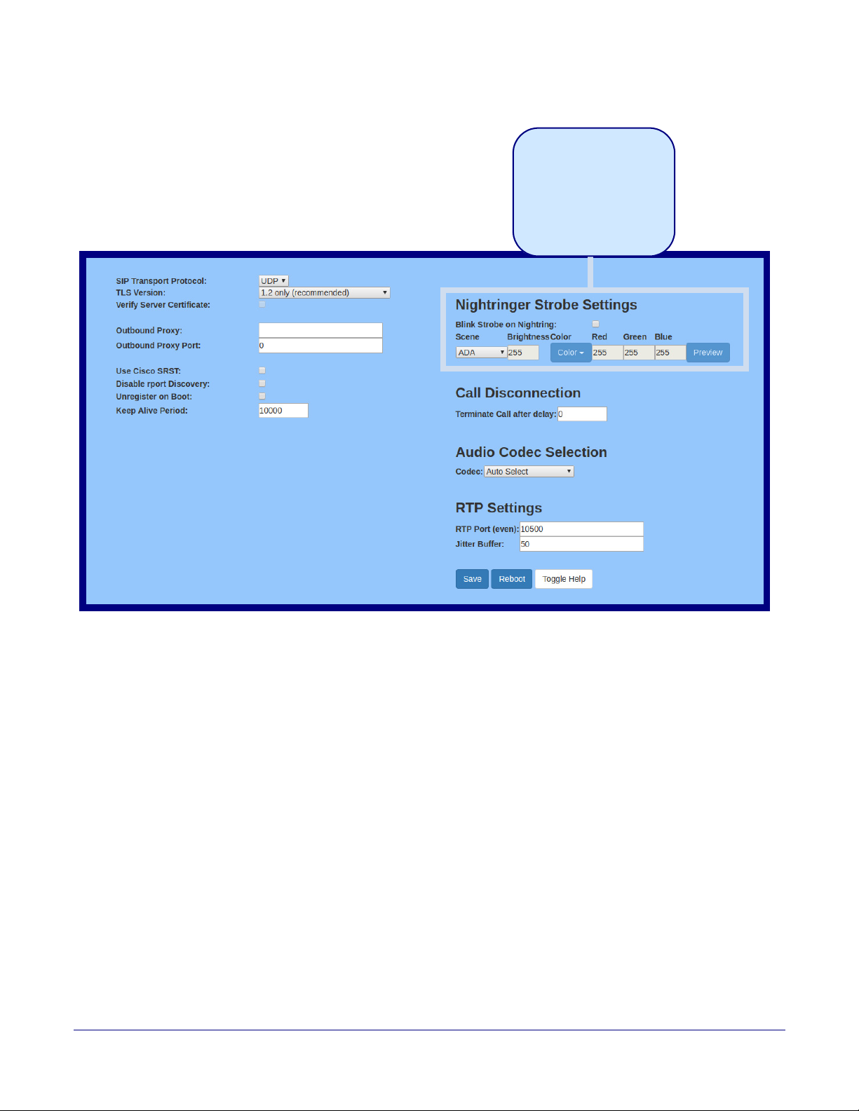
Installing the Singlewire InformaCast Indoor Intercom with Keypad
The strobe settings will only
appear if a CyberData Strobe
product is connected to your
device.
If a CyberData Strobe product
is not connected to your
device, you will not see the
strobe settings.
Configure the SIP (Session Initiation Protocol) Parameters
Figure 2-28. SIP Configuration Page
52
Operations Guide 931640A CyberData Corporation
Page 60

Installing the Singlewire InformaCast Indoor Intercom with Keypad
Configure the SIP (Session Initiation Protocol) Parameters
2. On the SIP page, enter values for the parameters indicated in Ta b le 2-15.
53
Note The question mark icon (
after the To
ggle Help button is pressed.
) in the following table shows which web page items will be defined
Table 2-15. SIP Configuration Parameters
Web Page Item Description
SIP Settings
Enable SIP Operation When enabled, the device will transmit, receive, and process SIP messages
according to the configured SIP settings below.
Register with a SIP Server When enabled, the device will attempt to register to the configured SIP Server(s) on
this page. To configure the device to send and receive point-to-point SIP calls,
enable SIP Operation and disable Register with a SIP Server (see Section
2.4.9.2, "Point-to-Point Configuration").
Get SIP Params from InformaCast When enabled, the device will get its SIP configuration parameters from the
InformaCast server. This will override the manually entered/auto provisioned SIP
configuration.
Primary SIP Server Enter the SIP server address as an IPv4 address in dotted decimal notation or a
fully qualified domain name. This parameter also becomes the host portion of the
SIP-URI for the device's extension on the primary SIP server. This field can accept
entries of up to 255 characters in length.
Primary SIP User ID Specify the SIP User ID for the Primary SIP Server. This parameter becomes the
user portion of the SIP-URI for the device's extension on the primary SIP server.
Enter up to 64 alphanumeric characters.
Primary SIP Auth ID Specify the Authenticate ID for the Primary SIP Server. This parameter is required
for SIP registration authentication. Enter up to 64 alphanumeric characters.
Primary SIP Auth Password Specify the Authenticate Password for the Primary SIP Server. This parameter is
required for SIP registration authentication. Enter up to 64 alphanumeric characters.
Re-registration Interval (in seconds) The SIP Re-registration interval (in seconds) is the SIP Registration lease time, also
known as the expiry. The supported range is 30-3600 seconds. Enter up to 4 digits.
Backup SIP Server 1 Enter the backup SIP server address as an IPv4 address in dotted decimal notation
or a fully qualified domain name. This parameter also becomes the host portion of
the SIP-URI for the device's extension on the backup SIP server. This field can
accept entries of up to 255 characters in length.
Backup SIP User ID 1 Specify the SIP User ID for the first backup SIP Server. This parameter becomes
the user portion of the SIP-URI for the device's extension on the first backup SIP
server. Enter up to 64 alphanumeric characters.
Backup SIP Auth ID Specify the Authenticate ID for the first backup SIP server. This parameter is
required for SIP registration authentication. Enter up to 64 alphanumeric characters.
Backup SIP Auth Password Specify the Authenticate Password for the first backup SIP server. This parameter is
required for SIP registration authentication. Enter up to 64 alphanumeric characters.
Re-registration Interval (in seconds) The SIP Re-registration interval (in seconds) is the SIP Registration lease time, also
known as the expiry. The supported range is 30-3600 seconds. Enter up to 4 digits.
Backup SIP Server 2 Enter a second backup SIP server address as an IPv4 address in dotted decimal
notation or a fully qualified domain name. This parameter also becomes the host
portion of the SIP-URI for the device's extension on the second backup SIP server.
This field can accept entries of up to 255 characters in length.
Operations Guide 931640A CyberData Corporation
Page 61

Installing the Singlewire InformaCast Indoor Intercom with Keypad
Configure the SIP (Session Initiation Protocol) Parameters
Table 2-15. SIP Configuration Parameters (continued)
Web Page Item Description
Backup SIP User ID Specify the SIP User ID for the second backup SIP Server. This parameter
becomes the user portion of the SIP-URI for the device's extension on the second
backup SIP server. Enter up to 64 alphanumeric characters.
Backup SIP Auth ID Specify the Authenticate ID for the second backup SIP server. This parameter is
required for SIP registration authentication. Enter up to 64 alphanumeric characters.
Backup SIP Auth Password Specify the Authenticate Password for the second backup SIP server. This
parameter is required for SIP registration authentication. Enter up to 64
alphanumeric characters.
Re-registration Interval (in seconds) The SIP Re-registration interval (in seconds) is the SIP Registration lease time, also
known as the expiry. The supported range is 30-3600 seconds. Enter up to 4 digits.
Remote SIP Port The Remote SIP Port is the port number the device will use as the destination port
when sending SIP messages. The default Remote SIP Port is 5060. The supported
range is 0-65536. Enter up to 5 digits.
Local SIP Port The Local SIP Port is the port number the device will use to receive SIP messages.
The default Local SIP Port is 5060. The supported range is 0-65536. Enter up to 5
digits.
SIP Transport Protocol Choose the transport protocol for SIP signaling. This will affect all extensions,
including the Nightringer. Default is UDP.
54
TLS Version Choose the TLS version for SIP over TLS. Modern security standards strongly
recommend using TLS 1.2.
Verify Server Certificate When enabled, the device will verify the authenticity of the server during the TLS
handshake by its certificate and common name. The TLS handshake will be aborted
if the server is deemed to be inauthentic and SIP registration will not proceed.
Outbound Proxy Enter the Outbound Proxy address as an IPv4 address in dotted decimal notation or
a fully qualified domain name (FQDN). When an IP address is configured, the
device will send all SIP messages to this IP address. When an FQDN is configured,
the device will run DNS NAPTR, SRV, and A queries on the FQDN to resolve an IP
address to which it will send all SIP messages. This field can accept entries of up to
255 characters in length.
Outbound Proxy Port The Outbound Proxy Port is port number used as the destination port when sending
SIP messages to the outbound proxy. A value of 0 will default to 5060. The
supported range is 0-65536. Enter up to 5 digits.
Use Cisco SRST When enabled, the backup servers are handled according to Cisco SRST
(Survivable Remote Site Telephony). It is required for use in clustered Cisco Unified
Communications Manager topologies.
Disable rport Discovery Disabling rport Discovery will prevent the device from including the public WAN IP
address and port number in the contact information that is sent to the remote SIP
servers. This will generally only need to be enabled when using an SBC or SIP ALG
in conjunction with a remote SIP server.
Unregister on Boot When enabled, the device will send one registration with an expiry of 0 on boot.
Keep Alive Period The minimum time in milliseconds between keep-alive packets sent for nat traversal.
A value of 0 will disable keep alive packets.
SIP Ring Strobe Settings The following strobe settings will only appear if a CyberData Strobe product is
connected to your device. If a CyberData Strobe product is not connected to
your device, you will not see the strobe settings.
Blink Strobe on Ring When selected, the Strobe will blink a scene when ringing.
Operations Guide 931640A CyberData Corporation
Page 62
Installing the Singlewire InformaCast Indoor Intercom with Keypad
Configure the SIP (Session Initiation Protocol) Parameters
Table 2-15. SIP Configuration Parameters (continued)
Web Page Item Description
Scene Select desired scene (only one may be chosen).
ADA Compliant Strobe will blink ON at the specified brightness for 150ms then OFF for 350ms
during the duration of the event.
Slow Fade Strobe will increase in brightness from 0 to the specified brightness and back to 0
over the course of about 3.5 seconds during the duration of the event.
Fast Fade Strobe will increase in brightness from 0 to the specified brightness and back to 0
over the course of about 1.5 seconds during the duration of the event.
Slow Blink Strobe will blink ON at the specified brightness for one second then OFF for one
second during the duration of the event.
Fast Blink Strobe will blink ON at the specified brightness then OFF five times per second
during the duration of the event.
Color Select desired color (only one may be chosen).
Brightness How bright the strobe will blink when there is a SIP Ring. This is the maximum
brightness for “fade” type scenes.
Red The red LED value for SIP Ring.
55
Green The green LED value for SIP Ring.
Blue The blue LED value for SIP Ring.
Use this button to preview the strobe flashing behavior for the SIP Ring Strobe
Settings.
SIP Call Strobe Settings The following strobe settings will only appear if a CyberData Strobe product is
connected to your device. If a CyberData Strobe product is not connected to
your device, you will not see the strobe settings.
Blink Strobe during Call When selected, the Strobe will blink a scene during a call.
Scene Select desired scene (only one may be chosen).
ADA Compliant Strobe will blink ON at the specified brightness for 150ms then OFF for 350ms
during the duration of the event.
Slow Fade Strobe will increase in brightness from 0 to the specified brightness and back to 0
over the course of about 3.5 seconds during the duration of the event.
Fast Fade Strobe will increase in brightness from 0 to the specified brightness and back to 0
over the course of about 1.5 seconds during the duration of the event.
Slow Blink Strobe will blink ON at the specified brightness for one second then OFF for one
second during the duration of the event.
Fast Blink Strobe will blink ON at the specified brightness then OFF five times per second
during the duration of the event.
Color Select desired color (only one may be chosen).
Brightness How bright the strobe will blink when there is a SIP Call. This is the maximum
brightness for “fade” type scenes.
Red The red LED value for SIP Call.
Green The green LED value for SIP Call.
Blue The blue LED value for SIP Call.
Operations Guide 931640A CyberData Corporation
Page 63
Installing the Singlewire InformaCast Indoor Intercom with Keypad
Configure the SIP (Session Initiation Protocol) Parameters
Table 2-15. SIP Configuration Parameters (continued)
Web Page Item Description
Use this button to preview the strobe flashing behavior for the SIP Call Strobe
Settings.
MWI Strobe Settings The following strobe settings will only appear if a CyberData Strobe product is
connected to your device. If a CyberData Strobe product is not connected to
your device, you will not see the strobe settings.
Blink Strobe on MWI When selected, the strobe will blink a scene when a voicemail is waiting for its
extension.
Scene Select desired scene (only one may be chosen).
ADA Compliant Strobe will blink ON at the specified brightness for 150ms then OFF for 350ms
during the duration of the event.
Slow Fade Strobe will increase in brightness from 0 to the specified brightness and back to 0
over the course of about 3.5 seconds during the duration of the event.
Fast Fade Strobe will increase in brightness from 0 to the specified brightness and back to 0
over the course of about 1.5 seconds during the duration of the event.
Slow Blink Strobe will blink ON at the specified brightness for one second then OFF for one
second during the duration of the event.
Fast Blink Strobe will blink ON at the specified brightness then OFF five times per second
during the duration of the event.
56
MWI Call Color Select desired color (only one may be chosen).
Brightness How bright the strobe will blink when there is a message waiting. This is the
maximum brightness for “fade” type scenes.
Red The red LED value for MWI.
Green The green LED value for MWI.
Blue The blue LED value for MWI.
Use this button to preview the strobe flashing behavior for the MWI Strobe
Settings.
Nightringer Settings
SIP Server Enter the SIP server address as an IPv4 address in dotted decimal notation or a
fully qualified domain name. This parameter also becomes the host portion of the
SIP-URI for the device's Nightringer extension on the SIP server. This field can
accept entries of up to 255 characters in length.
SIP User ID Specify the SIP User ID for the SIP server. This parameter becomes the user
portion of the SIP-URI for the device's Nightringer extension. Enter up to 64
alphanumeric characters.
SIP Auth ID Specify the Authenticate ID for the SIP Server. This parameter is required for SIP
registration authentication. Enter up to 64 alphanumeric characters.
SIP Auth Password Specify the Authenticate Password for the SIP Server. This parameter is required for
SIP registration authentication. Enter up to 64 alphanumeric characters.
Re-registration Interval (in seconds) The SIP Re-registration Interval (in seconds) is the SIP Registration lease time, also
known as the expiry. The supported range is 30-3600 seconds. Enter up to 4 digits.
Operations Guide 931640A CyberData Corporation
Page 64
Installing the Singlewire InformaCast Indoor Intercom with Keypad
Configure the SIP (Session Initiation Protocol) Parameters
Table 2-15. SIP Configuration Parameters (continued)
Web Page Item Description
Nightringer Strobe Settings The following strobe settings will only appear if a CyberData Strobe product is
connected to your device. If a CyberData Strobe product is not connected to
your device, you will not see the strobe settings.
Blink Strobe on Nightring When selected, the Strobe will blink a scene when the Nightringer is ringing.
Scene Select desired scene (only one may be chosen).
ADA Compliant Strobe will blink ON at the specified brightness for 150ms then OFF for 350ms
during the duration of the event.
Slow Fade Strobe will increase in brightness from 0 to the specified brightness and back to 0
over the course of about 3.5 seconds during the duration of the event.
Fast Fade Strobe will increase in brightness from 0 to the specified brightness and back to 0
over the course of about 1.5 seconds during the duration of the event.
Slow Blink Strobe will blink ON at the specified brightness for one second then OFF for one
second during the duration of the event.
Fast Blink Strobe will blink ON at the specified brightness then OFF five times per second
during the duration of the event.
Color Select desired color (only one may be chosen).
Brightness How bright the strobe will blink when the Nightringer is ringing. This is the maximum
brightness for “fade” type scenes.
57
Red The red LED value for Nightringer.
Green The green LED value for Nightringer.
Blue The blue LED value for Nightringer.
Use this button to preview the strobe flashing behavior for the Nightringer Strobe
Settings.
Call Disconnection
Terminate Call After Delay Automatically terminate an active call after a given delay in seconds. A value of 0
will disable this function. Enter up to 8 digits.
Audio Codec Selection
Codec Select the desired codec (only one may be chosen).
RTP Settings
RTP Port (even) Specify the port number used for the RTP stream after establishing a SIP call. This
port number must be an even number and defaults to 10500. The supported range
is 0-65536. Enter up to 5 digits.
Jitter Buffer Specify the size of the jitter buffer (in milliseconds) used for SIP calls. Valid values
are 50-1000.
Click the Save button to save your configuration settings.
Click on the Reboot button to reboot the system.
Operations Guide 931640A CyberData Corporation
Page 65

Installing the Singlewire InformaCast Indoor Intercom with Keypad
Configure the SIP (Session Initiation Protocol) Parameters
Table 2-15. SIP Configuration Parameters (continued)
Web Page Item Description
Click on the Toggle Help button to see a short description of some of the web page
items. First click on the Toggle Help button, and you will see a question mark ( )
appear next to some of the web page items. Move the mouse pointer to hover over a
question mark to see a short description of a specific web page item.
Note For specific server configurations, go to the following website address:
https://www.cyberdata.net/pages/connecting-to-ip-pbx-servers
2.4.9.1 Dial Out Extension Strings and DTMF Tones (using rfc2833)
On the SIP Configuration Page, dial out extensions support the addition of comma delimited
pauses and sending additional DTMF tones (using rfc2833). The first comma will pause three
seconds aft
seconds. A pause of one second will be sent after each numerical digit.
Extension String Resulting Action
er a call is first established with a remote device. Subsequent commas will pause for 2
Table 2-16. Examples of Dial-Out Extension Strings
58
302 Dial out extension 302 and establish a call
302,2 Dial out extension 302 and establish a call, wait 3 seconds then send the
DTMF tone
302,25,,,4,,1 Dial out extension 302 and establish a call, wait 3 seconds then send the
DTMF tone
tone 4, wait 4 seconds, send out DTMF tone 1
'2'
'2', send out DTMF tone 5, wait 6 seconds, send out DTMF
Note The maximum number of total characters in the dial-out field is 64.
Operations Guide 931640A CyberData Corporation
Page 66
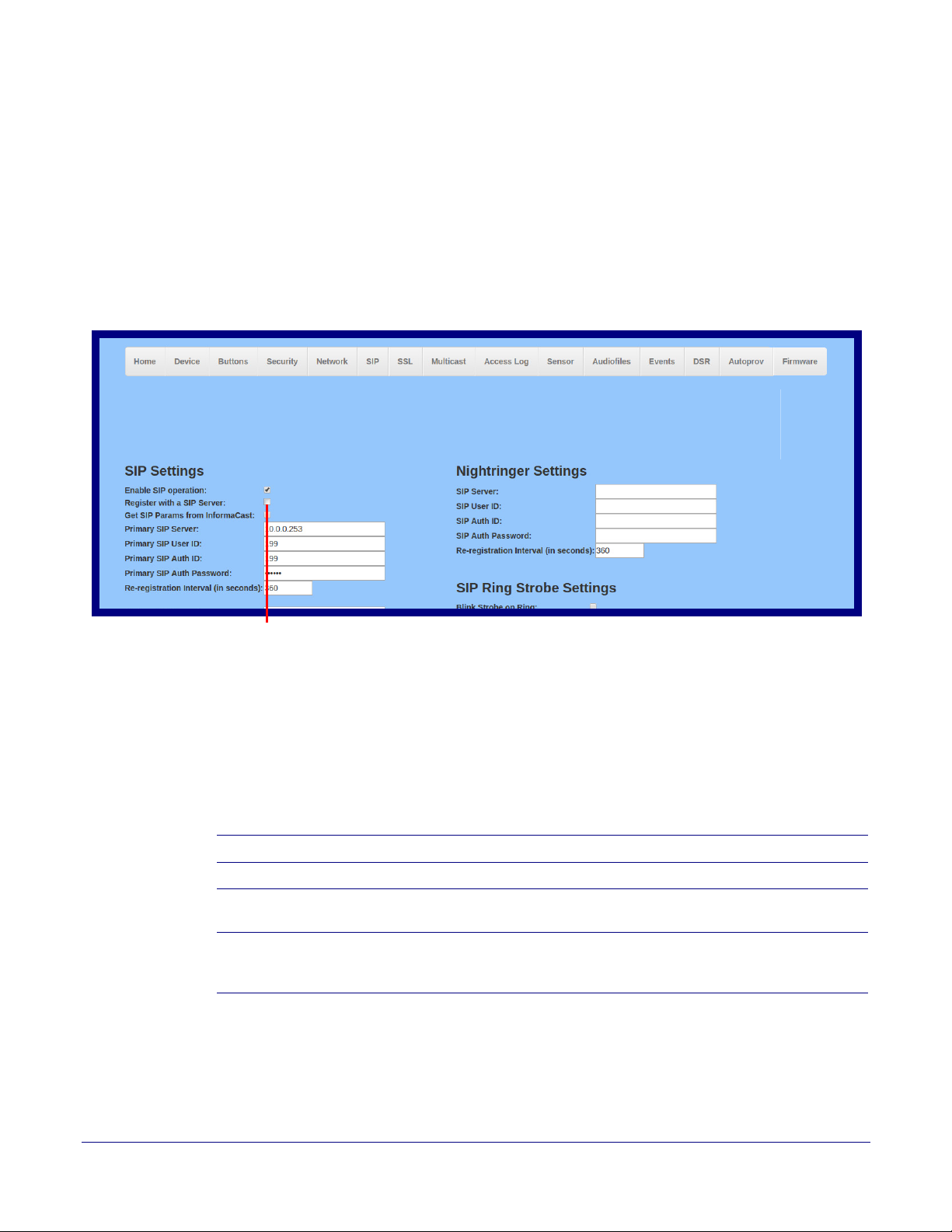
2.4.9.2 Point-to-Point Configuration
Device is set to NOT register with a SIP server
Singlewire Keypad Intercom
When the device is set to not register with a SIP server (see Figure 2-29), it is possible to set the
device to dial out to a single endpoint.
In this case, the dial-out extension should be the IP address of the remote device. The device can
a
lso receive Point-to-Point calls. The delayed DTMF functionality is available in the Point-to-Point
Mode.
Note Receiving point-to-point SiP calls may not work with all phones.
Figure 2-29. SIP Page Set to Point-to-Point Mode
Installing the Singlewire InformaCast Indoor Intercom with Keypad
Configure the SIP (Session Initiation Protocol) Parameters
59
2.4.9.3 Delayed DTMF
On the SIP Configuration page the dial out extension supports the addition of comma delimited
pauses and sending additional DTMF tones (using rfc2833). The first comma will pause three
seconds after a call is first established with a remote device. Subsequent commas will pause for 2
seconds. A pause of one second will be sent after each numerical digit.
Extension String Resulting Action
302 Dial out extension 302 and establish a call
302,2 Dial out extension 302 and establish a call, wait 3 seconds then send the
302,25,,,4,,1 Dial out extension 302 and establish a call, wait 3 seconds then send the
Note The maximum number of total characters in the dial-out field is 25.
Table 2-17. Examples of Dial-Out Extension Strings
DTMF tone
DTMF tone
tone 4, wait 4 seconds, send out DTMF tone 1
'2'
'2', send out DTMF tone 5, wait 6 seconds, send out DTMF
Operations Guide 931640A CyberData Corporation
Page 67
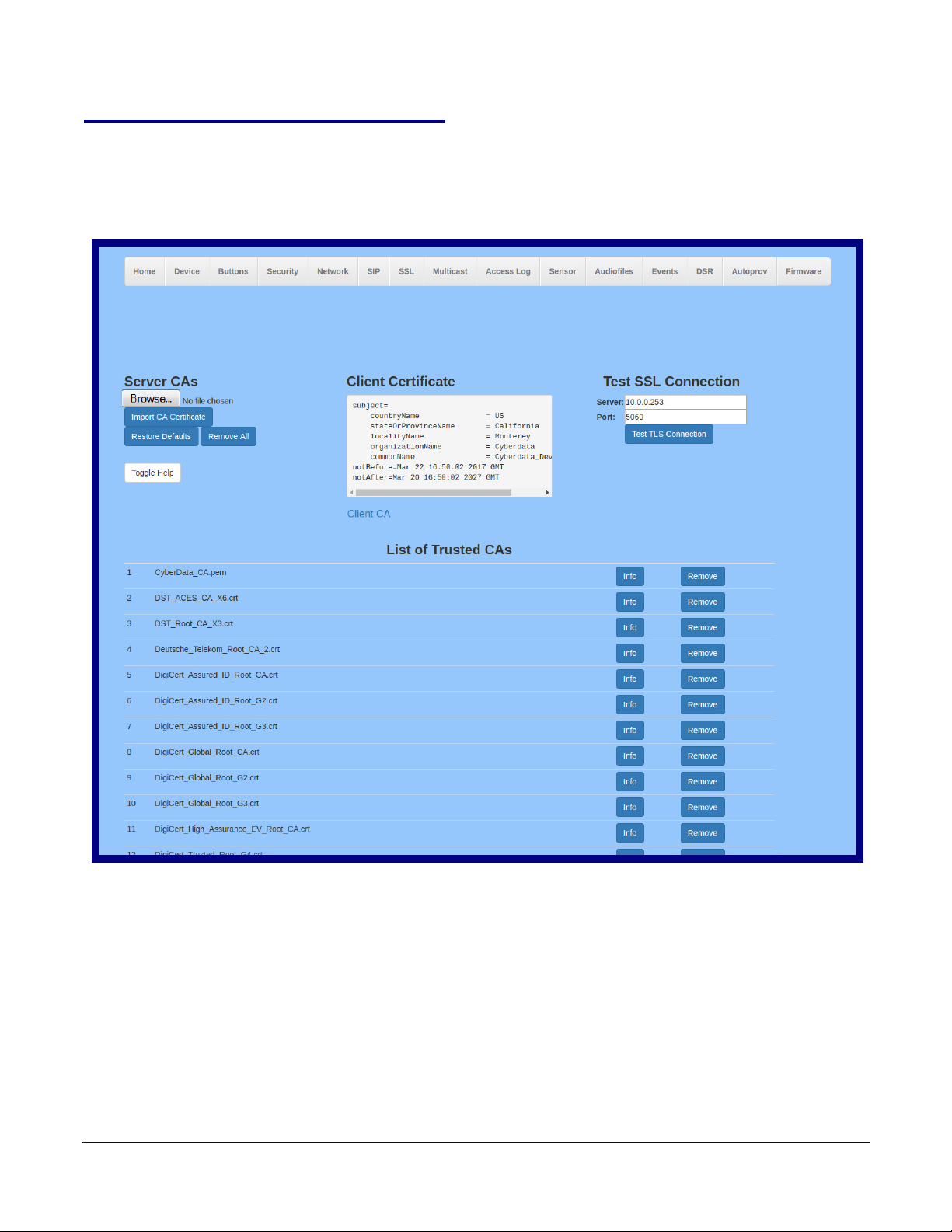
2.4.10 Configure the SSL Parameters
Singlewire Keypad Intercom
1. Click SSL menu button to open the SSL page (Figure 2-37).
Figure 2-30. SSL Configuration Page
Installing the Singlewire InformaCast Indoor Intercom with Keypad
Configure the SSL Parameters
60
Operations Guide 931640A CyberData Corporation
Page 68
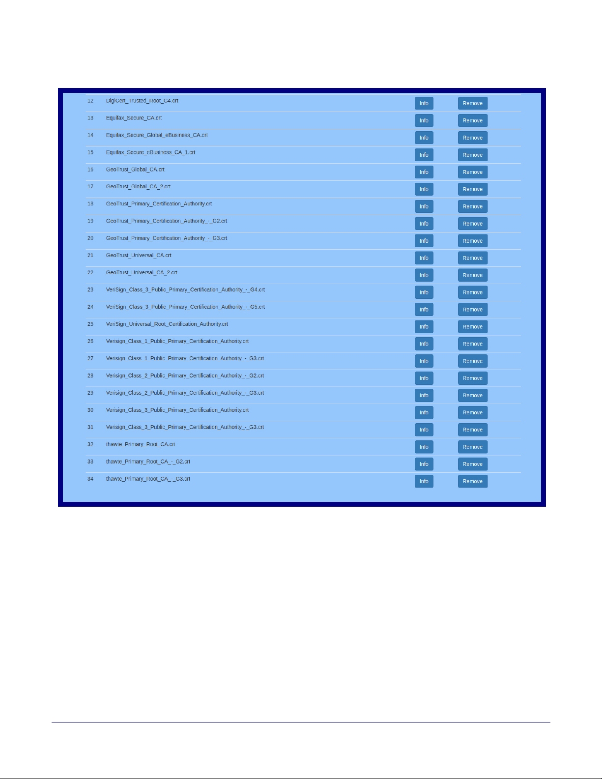
Installing the Singlewire InformaCast Indoor Intercom with Keypad
Figure 2-31. SSL Configuration Page
Configure the SSL Parameters
61
Operations Guide 931640A CyberData Corporation
Page 69
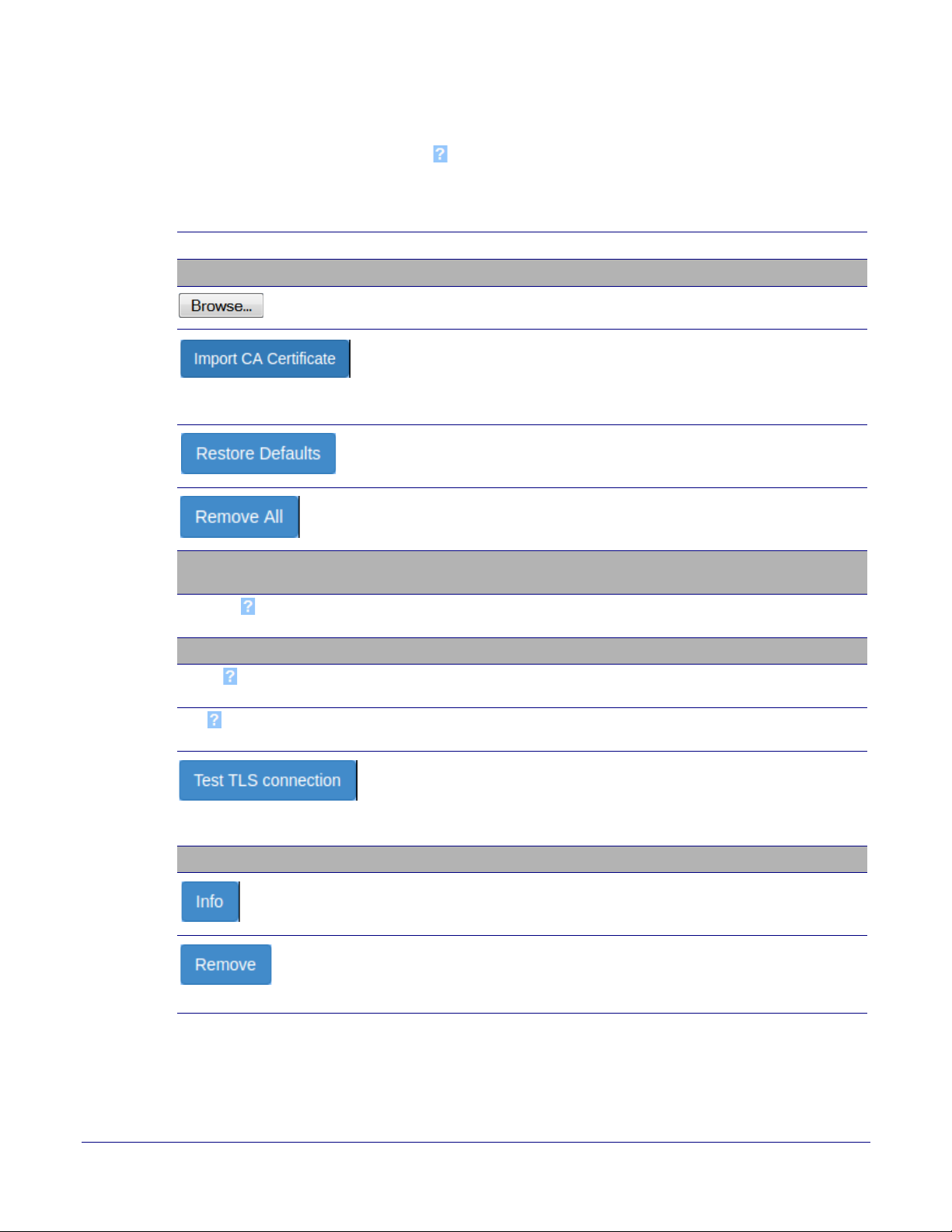
Installing the Singlewire InformaCast Indoor Intercom with Keypad
Configure the SSL Parameters
2. On the SSL page, enter values for the parameters indicated in Ta bl e 2-18.
62
Note The question mark icon (
after the To
ggle Help button is pressed.
) in the following table shows which web page items will be defined
Table 2-18. SSL Configuration Parameters
Web Page Item Description
Server CAs
Use this button to select a configuration file to import.
Click Browse to select a CA certificate to import. After selecting
a server certificate authority (CA), click Import CA Certificate to
import it to the list of trusted CAs. CAs are used to validate the
certificate presented by the server when establishing a TLS
connection.
Restore Defaults will restore the default list of registered CAs
and Remove All will remove all registered CAs.
Restore Defaults will restore the default list of registered CAs
and Remove All will remove all registered CAs.
Client Certificate When doing mutual authentication this device will present a client
certificate with these parameters.
Client CA Right click and Save Link As... to get the Cyberdata CA used to
sign this client certificate.
Test SSL Connection
Server The ssl test server address as a fully qualified domain name or in
IPv4 dotted decimal notation.
Port The ssl test server port. The supported range is 0-65536. SIP
connections over TLS to port 5060 will do the same.
Use this button to test a TLS connection to a remote server. This
will attempt to make a socket connection to the configured test
server and port and report the success or failure. This can be
used to debug TLS connection issues separate from SIP
registration issues.
List of Trusted CAs
Provides details of the certificate. After clicking on this button, the
Certificate Info Window appears. See Section 2.4.10.1,
"Certificate Info Window".
Removes this certificate from the list of trusted certificates. After
clicking on this button, the Remove Server Certificate Window
appears. See Section 2.4.10.2, "Remove Server Certificate
Window".
Operations Guide 931640A CyberData Corporation
Page 70
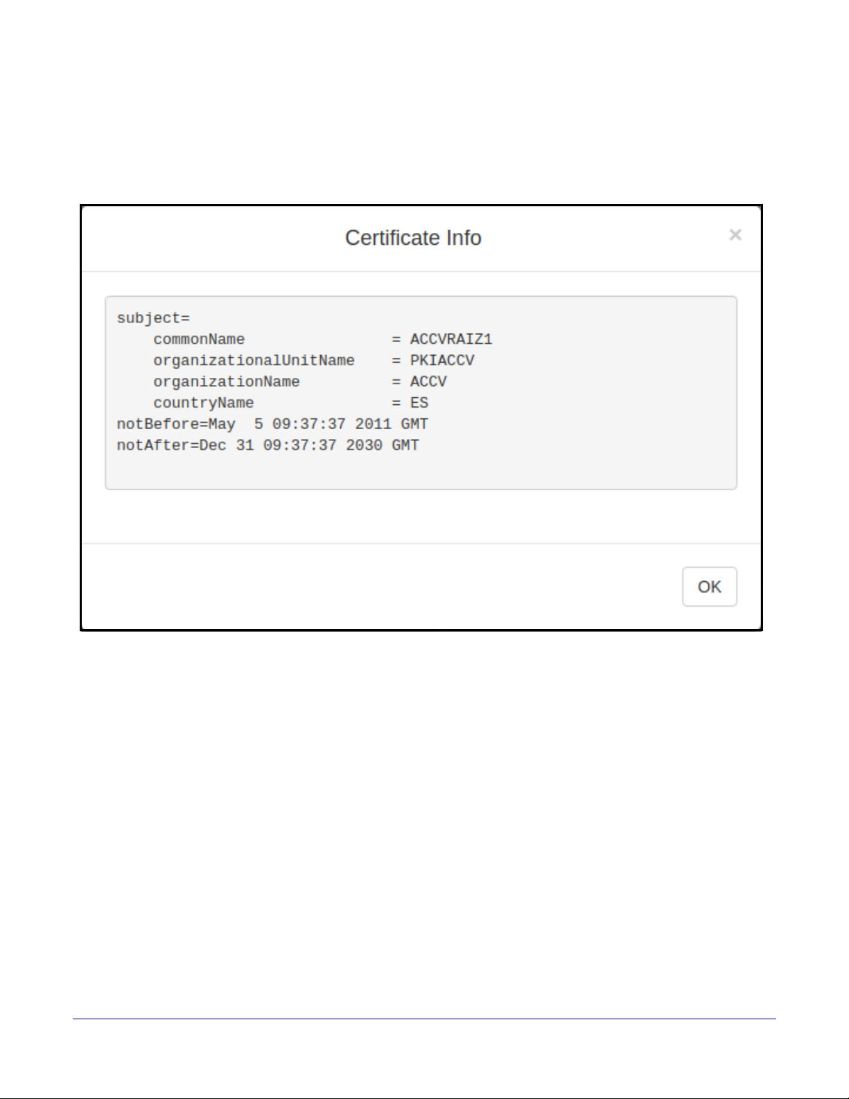
2.4.10.1 Certificate Info Window
The Certificate Info Window provides details of the certificate. This window appears after clicking
on the Info button. See
Figure 2-32. Certificate Info Window
Figure 2-32.
Installing the Singlewire InformaCast Indoor Intercom with Keypad
Configure the SSL Parameters
63
Operations Guide 931640A CyberData Corporation
Page 71
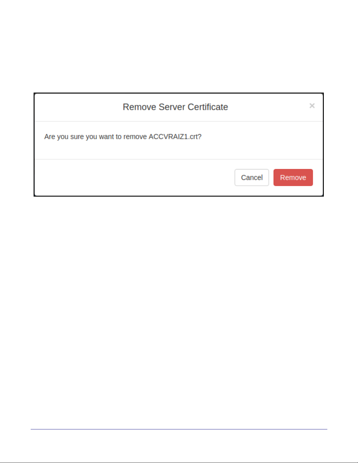
2.4.10.2 Remove Server Certificate Window
The Remove Server Certificate Window will ask if the user wants to remove a certificate from the
list of trusted certificates. This window appears after clicking on the Remove button. See
33.
Figure 2-33. Remove Server Certificate Window
Installing the Singlewire InformaCast Indoor Intercom with Keypad
Configure the SSL Parameters
Figure 2-
64
Operations Guide 931640A CyberData Corporation
Page 72

Installing the Singlewire InformaCast Indoor Intercom with Keypad
2.4.11 Configure the Multicast Parameters
The Multicast Configuration page allows the device to join up to ten paging zones for receiving
ulaw/alaw encoded RTP audio streams.
A paging zone can consist of one or many CyberData multicast group-enabled products. There is no
limit to how many speakers can be in a given paging zone. Each multicast group is defined by a
multicast address and port number.
Each multicast group is assigned a priority, allowing simultaneously arriving pages to be serviced
based on importance. Multicast groups are compatible with IGMP through version 3. The device
supports simultaneous SIP and Multicast.
1. Click on the Multicast menu button to open the Multicast page. See Figure 2-34.
Configure the Multicast Parameters
65
Operations Guide 931640A CyberData Corporation
Page 73
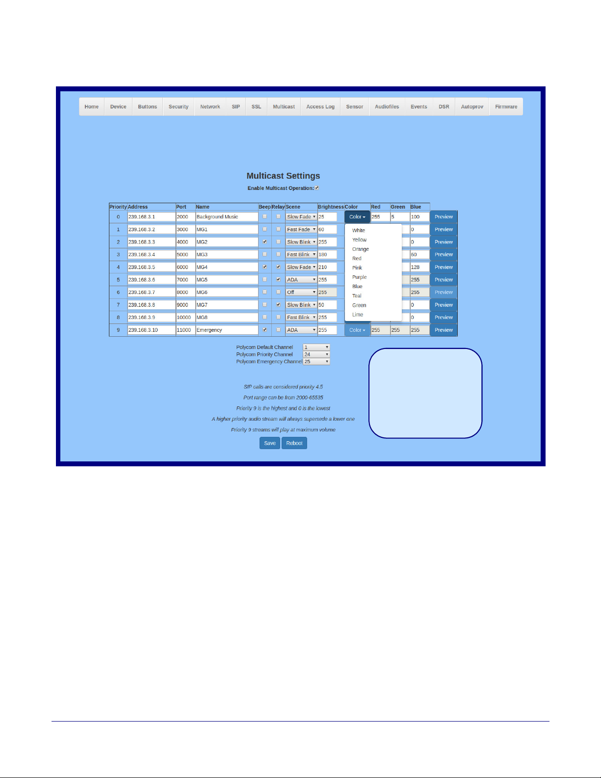
Installing the Singlewire InformaCast Indoor Intercom with Keypad
The strobe settings will only
appear if a CyberData Strobe
product is connected to your
device.
If a CyberData Strobe product
is not connected to your
device, you will not see the
strobe settings.
Singlewire Keypad Intercom
Figure 2-34. Multicast Configuration Page
Configure the Multicast Parameters
66
Operations Guide 931640A CyberData Corporation
Page 74

Installing the Singlewire InformaCast Indoor Intercom with Keypad
Configure the Multicast Parameters
2. On the Multicast page, enter values for the parameters indicated in Ta bl e 2-19.
67
Note The question mark icon (
after the To
ggle Help button is pressed.
) in the following table shows which web page items will be defined
Table 2-19. Multicast Page Parameters
Web Page Item Description
Enable Multicast Operation Enables or disables multicast operation.
Priority Indicates the priority for the multicast group. Priority 9
is the highest (emergency
streams). 0 is the lowest (background music). SIP calls are considered priority 4.5.
See Section 2.4.11.1, "Assigning Priority" for more details.
Address Enter the multicast IP Address for this multicast group (15 character limit).
Por t Enter the port number for this multicast group (5 character limit [range can be from
2000 to 65535]).
Note: The multicast ports have to be even values. The webpage will enforce this
restriction.
Name Assign a descriptive name for this multicast group (25 character limit).
Beep When selected, the device will play a beep before multicast audio is sent.
Relay When selected, the device will activate a relay before multicast audio is sent.
Scene Select desired scene (only one may be chosen).
Note: The strobe settings will only appear if you are using the Strobe Kit. If
y
ou are not using the Strobe Kit, you will not see the strobe settings.
ADA Compliant
Strobe will blink ON at the specified brightness for 150ms then OFF for 350ms
during the duration of the event.
Slow Fade
Strobe will increase in brightness from 0 to the specified brightness and back to 0
over the course of about 3.5 seconds during the duration of the event.
Fast Fa de
Strobe will increase in brightness from 0 to the specified brightness and back to 0
over the course of about 1.5 seconds during the duration of the event.
Slow Blink
Strobe will blink ON at the specified brightness for one second then OFF for one
second during the duration of the event.
Fast Blink
Strobe will blink ON at the specified brightness then OFF five times per second
during the duration of the event.
Color
Brightness
Select desired color (only one may be chosen).
How bright the strobe will blink on a multicast page. This is the maximum
brightness for “fade” type scenes.
Red
Green
Blue
The red LED value for Multicast.
The green LED value for Multicast.
The blue LED value for Multicast.
Polycom Default Channel When a default Polycom channel/group number is selected, the device will
scribe to the default channel for one-way group pages. Group Numbers 1-25
sub
are supported. Or, select Disabled to disable this channel.
Polycom Priority Channel When a priority Polycom channel/group number is selected, the device will
subscribe to the priority channel for one-way group pages. Group Numbers 1-25
are supported. Or, select Disabled to disable this channel.
Operations Guide 931640A CyberData Corporation
Page 75
Installing the Singlewire InformaCast Indoor Intercom with Keypad
Configure the Multicast Parameters
Table 2-19. Multicast Page Parameters (continued)
Web Page Item Description
Polycom Emergency Channel When an emergency Polycom channel/group number is selected, the device will
subscribe to the default channel for one-way group pages. Group Numbers 1-25
are supported. Or, select Disabled to disable this channel.
Use this button to preview the strobe flashing behavior for the Multicast Strobe
Settings.
Click the Save button to save your configuration settings.
Click on the Reboot button to reboot the system.
2.4.11.1 Assigning Priority
The device will prioritize simultaneous audio streams according to their priority in the list.
If both SIP and Multicast is enabled, SIP audio streams are considered priority 4.5. SIP audio will
interrupt multicast streams with priority 0 through 4 and will be interrupted by multicast streams with
priority 5 through 9.
68
Ringtones and Nightringtones
During priority 9 multicast streams, the volume is set to maximum.
Note SIP calls, multicast streams, ring tones, ringback tones, and nightring tones are all
prioritized.
Ringtones all play at the same priority level. This means that it is possible to have a nightring tone
and a normal ringtone playing at the same time.
Operations Guide 931640A CyberData Corporation
Page 76
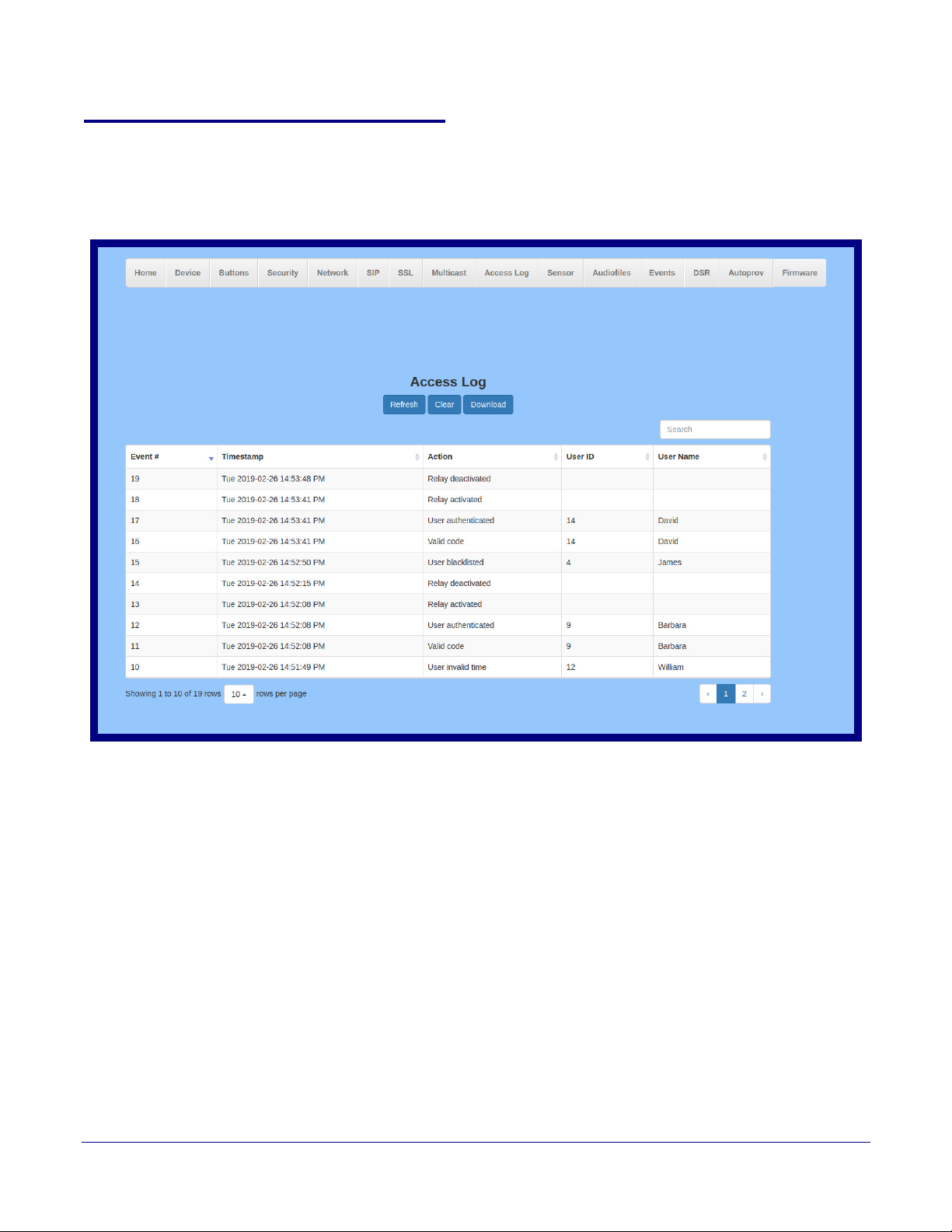
Installing the Singlewire InformaCast Indoor Intercom with Keypad
Singlewire Keypad Intercom
2.4.12 Configure the Access Log Parameters
1. Click the Access Log menu button to open the Access Log page (Figure 2-37).
Figure 2-35. Access Log Page
Configure the Access Log Parameters
69
Operations Guide 931640A CyberData Corporation
Page 77
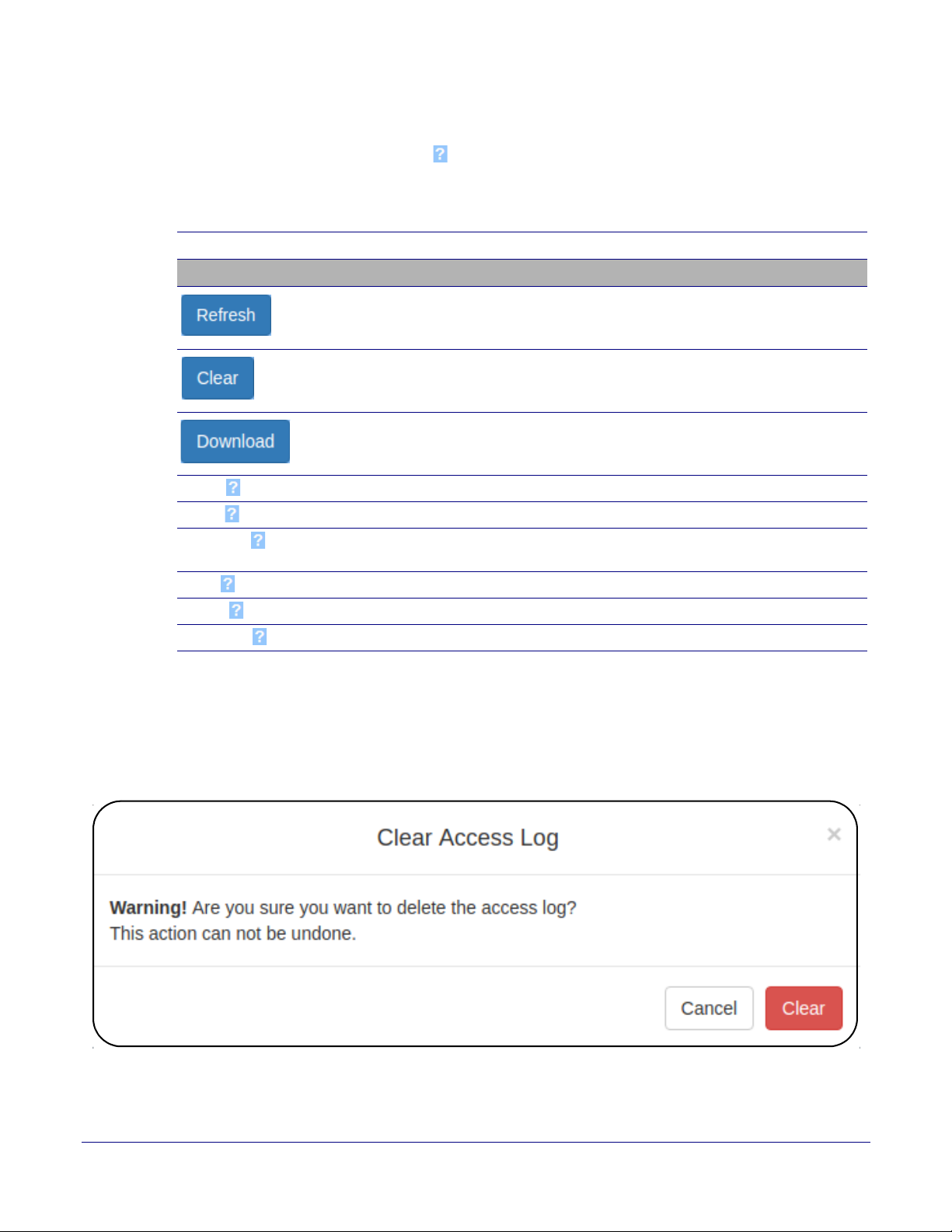
Installing the Singlewire InformaCast Indoor Intercom with Keypad
Configure the Access Log Parameters
2. On the Access Log page, enter values for the parameters indicated in Ta bl e 2-18.
70
Note The question mark icon (
after the To
ggle Help button is pressed.
) in the following table shows which web page items will be defined
Table 2-20. Access Log Configuration Parameters
Web Page Item Description
Access Log
Refresh the web page view new log entries.
Erases the log. When pressed, the Clear Access Log
Confirmation Window appears. See Section 2.4.12.1, "Clear
Access Log Confirmation Window".
Downloads the access log.
Search Search the access log.
Event # System generated number to identify the event.
Timestamp Displays the time of the event (Day of week Year-Month-Day
Hour:Minute:Seconds AM/PM).
Action Describes the event.
User ID Displays the ID number of the user.
User Name Displays the name of the user.
2.4.12.1 Clear Access Log Confirmation Window
The Clear Access Log Confirmation Window will ask if the user wants to delete the access log.
This window appears after clicking on the Clear button. See Figure 2-36.
Figure 2-36. Clear Access Log Confirmation W
indow
Operations Guide 931640A CyberData Corporation
Page 78
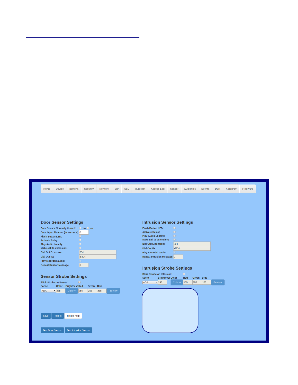
Installing the Singlewire InformaCast Indoor Intercom with Keypad
The strobe settings will only
appear if a CyberData Strobe
product is connected to your
device.
If a CyberData Strobe product
is not connected to your
device, you will not see the
strobe settings.
Singlewire Keypad Intercom
Configure the Sensor Configuration Parameters
2.4.13 Configure the Sensor Configuration Parameters
The door sensor (pins 5 and 6) on the header can be used to monitor a door's open or closed state.
There is an option on the Sensor page to trigger on an open or short condition on these pins. The
door sensor alarm will be activated when the Door Open Timeout parameter has been met.
The intrusion sensor is an optical sensor installed on the Intercom board and will be activated when
the Intercom is removed from the case.
Each sensor can trigger up to five different actions:
• Flash the LED until the sensor is deactivated (roughly 10 times/second)
• Activate the relay until the sensor is deactivated
• Loop an audio file out of the Intercom speaker until the sensor is deactivated
• Call an extension and establish two way audio
• Call an extension and play a pre-recorded audio file
Note Calling a preset extension can be set up as a point-to-point call, but currently can't send
delayed DTMF tones.
71
1. Click Sensor menu button to open the Sensor page (Figure 2-37).
Figure 2-37. Sensor Configuration Page
Operations Guide 931640A CyberData Corporation
Page 79

Installing the Singlewire InformaCast Indoor Intercom with Keypad
Configure the Sensor Configuration Parameters
2. On the Sensor page, enter values for the parameters indicated in Ta bl e 2-21.
72
Note The question mark icon (
after the To
ggle Help button is pressed.
) in the following table shows which web page items will be defined
Table 2-21. Sensor Configuration Parameters
Web Page Item Description
Door Sensor Settings
Door Sensor Normally Closed Select the inactive state of the door sensor. The door sensor is
also known as the Sense Input on the device's terminal block.
Door Open Timeout (in seconds) The time (in seconds) the device will wait before it performs an
action when the on-board door sensor is activated. The action(s)
performed are based on the configured Door Sensor Settings
below. Enter up to 5 digits.
Flash Button LED When selected, the Call button LED will flash until the on-board
door sensor is deactivated (roughly 10 times/second).
Activate Relay When selected, the device's on-board relay will be activated until
the on-board door sensor is deactivated.
Play Audio Locally When selected, the device will loop an audio file out of the
speaker until the door sensor is deactivated.
Make call to extension When selected, the device will call an extension when the on-
board door sensor is activated. Use the Dial Out Extension field
below to specify the extension the device will call.
Dial Out Extension Specify the extension the device will call when the on-board door
sensor is activated. Enter up to 64 alphanumeric characters.
Dial Out ID An additional Caller identification string added to outbound calls.
Enter up to 64 alphanumeric characters.
Play recorded audio When selected, the device will call the Dial Out Extension and
play an audio file to the phone answering the SIP call
(corresponds to Door Ajar on the Audiofiles page).
Repeat Sensor Message The number of times to repeat the audio message through the
local speaker or to the remote endpoint. A value of 0 will repeat
forever. Enter a value from 0-65536.
Sensor Strobe Settings The following strobe settings will only appear if a CyberData
Strobe product is connected to your device. If a CyberData
Strobe product is not connected to your device, you will not
see the strobe settings.
Blink Strobe on Sensor When selected, the Strobe will blink a scene when the sensor is
triggered.
Scene Select desired scene (only one may be chosen).
ADA Compliant Strobe will blink ON at the specified brightness for 150ms then
OFF for 350ms during the duration of the event.
Slow Fade Strobe will increase in brightness from 0 to the specified
brightness and back to 0 over the course of about 3.5 seconds
during the duration of the event.
Fast Fade Strobe will increase in brightness from 0 to the specified
brightness and back to 0 over the course of about 1.5 seconds
during the duration of the event.
Operations Guide 931640A CyberData Corporation
Page 80
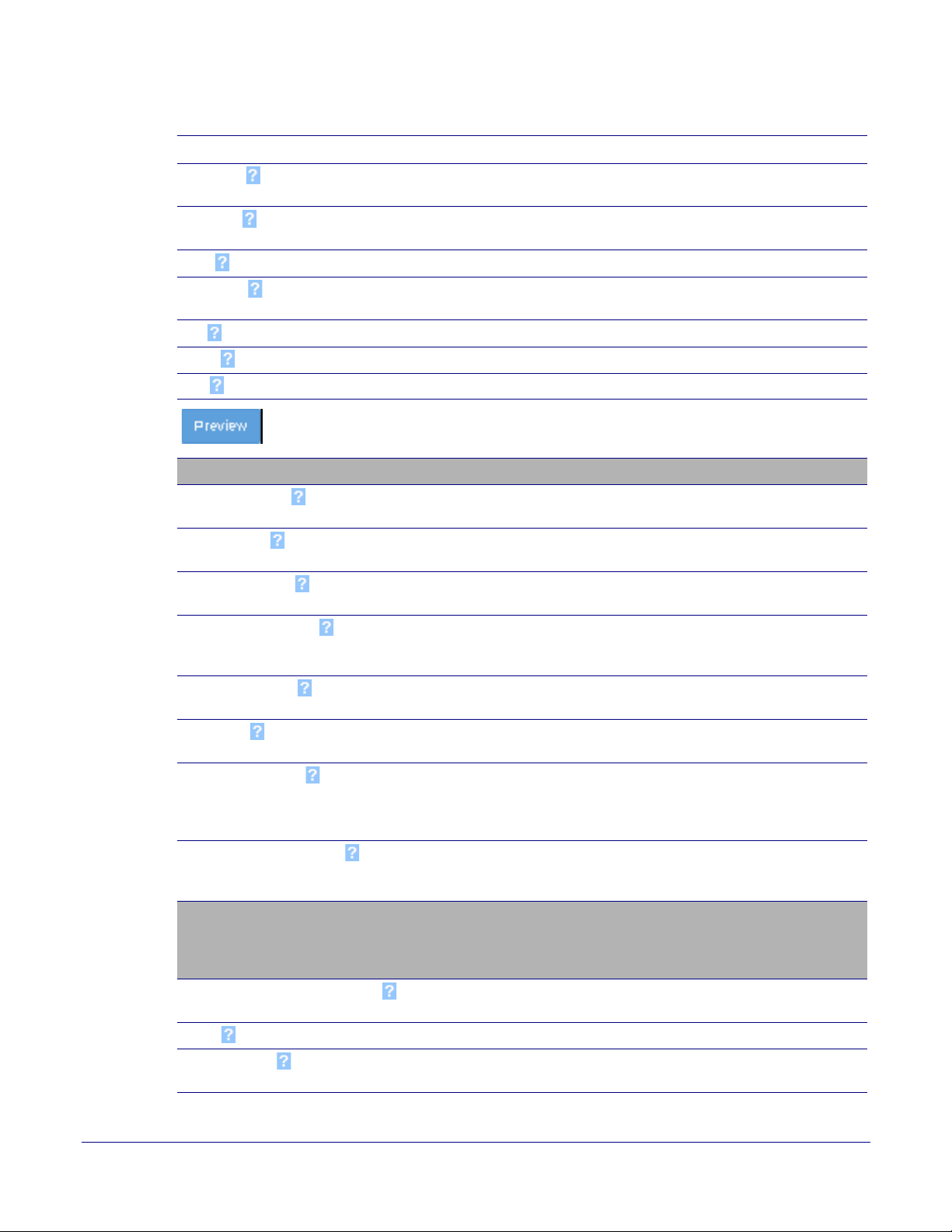
Installing the Singlewire InformaCast Indoor Intercom with Keypad
Configure the Sensor Configuration Parameters
Table 2-21. Sensor Configuration Parameters (continued)
Web Page Item Description
Slow Blink Strobe will blink ON at the specified brightness for one second
then OFF for one second during the duration of the event.
Fast Blink Strobe will blink ON at the specified brightness then OFF five
times per second during the duration of the event.
Color Select desired color (only one may be chosen).
Brightness How bright the strobe will blink when the sensor is triggered. This
is the maximum brightness for “fade” type scenes.
Red The red LED value for the Sensor.
Green The green LED value for the Sensor.
Blue The blue LED value for the Sensor.
Use this button to preview the strobe flashing behavior for the
Sensor Strobe Settings.
Intrusion Sensor Settings
Flash Button LED When selected, the Call button LED will flash until the intrusion
sensor is deactivated (roughly 10 times/second).
73
Activate Relay When selected, the device's on-board relay will be activated until
the intrusion sensor is deactivated.
Play Audio Locally When selected, the device will loop an audio file out of the
speaker until the intrusion sensor is deactivated.
Make call to extension When selected, the device will call an extension when the
intrusion sensor is activated. Use the Dial Out Extension field
below to specify the extension the device will call.
Dial Out Extension Specify the extension the device will call when the intrusion
sensor is activated. Enter up to 64 alphanumeric characters.
Dial Out ID An additional Caller identification string added to outbound calls.
Enter up to 64 alphanumeric characters.
Play recorded audio When selected, the device will call the Dial Out Extension and
play an audio file (corresponds to Intrusion Sensor Triggered
on the Audiofiles page) to the phone answering the SIP call
when the intrusion sensor is activated.
Repeat Intrusion Message The number of times to repeat the audio message through the
local speaker or to the remote endpoint. A value of 0 will repeat
forever. Enter a value from 0-65536.
Intrusion Sensor Strobe Settings The following strobe settings will only appear if a CyberData
Strobe product is connected to your device. If a CyberData
Strobe product is not connected to your device, you will not
see the strobe settings.
Blink Strobe on Intrusion Sensor When selected, the Strobe will blink a scene when the intrusion
sensor is triggered.
Scene Select desired scene (only one may be chosen).
ADA Compliant Strobe will blink ON at the specified brightness for 150ms then
OFF for 350ms during the duration of the event.
Operations Guide 931640A CyberData Corporation
Page 81
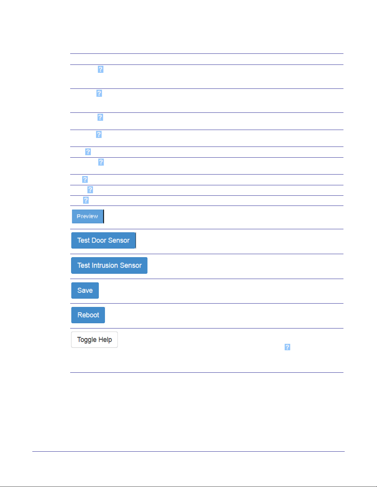
Installing the Singlewire InformaCast Indoor Intercom with Keypad
Configure the Sensor Configuration Parameters
Table 2-21. Sensor Configuration Parameters (continued)
Web Page Item Description
Slow Fade Strobe will increase in brightness from 0 to the specified
brightness and back to 0 over the course of about 3.5 seconds
during the duration of the event.
Fast Fade Strobe will increase in brightness from 0 to the specified
brightness and back to 0 over the course of about 1.5 seconds
during the duration of the event.
Slow Blink Strobe will blink ON at the specified brightness for one second
then OFF for one second during the duration of the event.
Fast Blink Strobe will blink ON at the specified brightness then OFF five
times per second during the duration of the event.
Color Select desired color (only one may be chosen).
Brightness How bright the strobe will blink when the intrusion sensor is
triggered. This is the maximum brightness for “fade” type scenes.
Red The red LED value for the Intrusion Sensor.
Green The green LED value for the Intrusion Sensor.
Blue The blue LED value for the Intrusion Sensor.
Use this button to preview the strobe flashing behavior for the
Intrusion Sensor Strobe Settings.
74
Click the Test Door Sensor button to test the door sensor.
Click the Test Intrusion Sensor button to test the Intrusion
sensor.
Click the Save button to save your configuration settings.
Click on the Reboot button to reboot the system.
Click on the Toggle Help button to see a short description of
some of the web page items. First click on the Toggle Help
button, and you will see a question mark ( ) appear next to
some of the web page items. Move the mouse pointer to hover
over a question mark to see a short description of a specific web
page item.
Operations Guide 931640A CyberData Corporation
Page 82
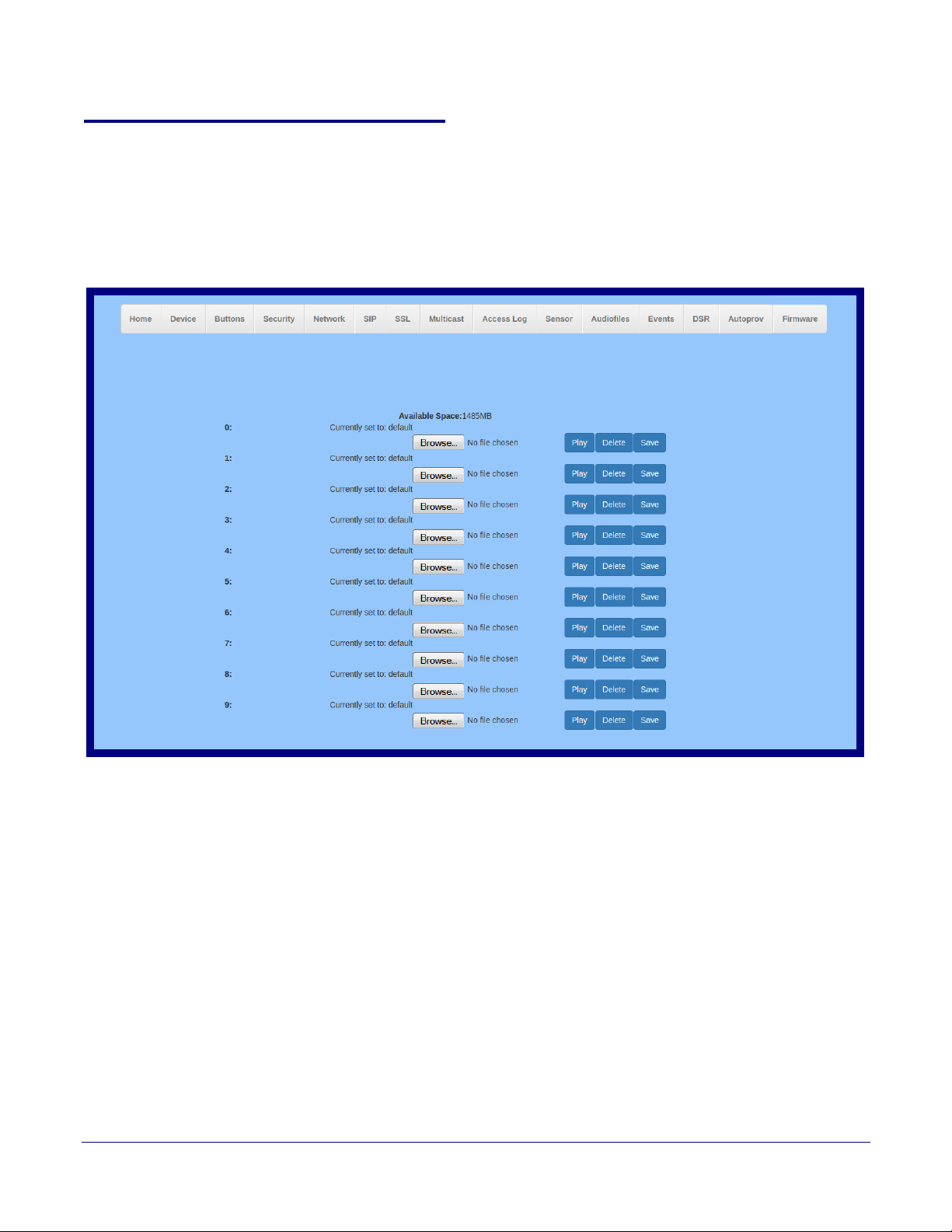
Installing the Singlewire InformaCast Indoor Intercom with Keypad
Singlewire Keypad Intercom
Configure the Audio Configuration Parameters
2.4.14 Configure the Audio Configuration Parameters
The Audiofiles page is used to add custom audio to the board. User uploaded audio will take
precedence over the audio files shipped with the Intercom.
1. Click on the Audiofiles menu button to open the Audiofiles page (Figure 2-38).
Figure 2-38. Audiofiles Configuration Page
75
Operations Guide 931640A CyberData Corporation
Page 83
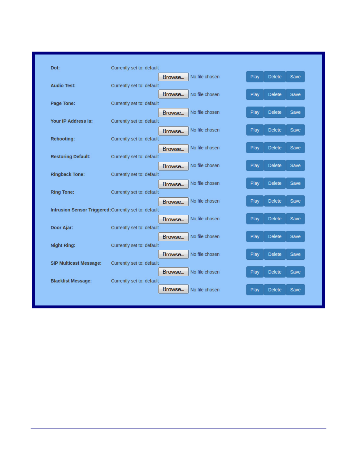
Installing the Singlewire InformaCast Indoor Intercom with Keypad
Figure 2-39. Audiofiles Page
Configure the Audio Configuration Parameters
76
Operations Guide 931640A CyberData Corporation
Page 84

Installing the Singlewire InformaCast Indoor Intercom with Keypad
Configure the Audio Configuration Parameters
2. On the Audiofiles page, enter values for the parameters indicated in Ta bl e 2-22.
77
Note The question mark icon (
after the To
ggle Help button is pressed.
) in the following table shows which web page items will be defined
Table 2-22. Audiofiles Configuration Parameters
Web Page Item Description
Available Space Shows the space available for the user to save custom audio files if they want to change the
message when the door or sensor is triggered.
0-9 The name of the audio configuration option is the same as th
e spoken audio that plays on
the board (24 character limit).
'0' corresponds to the spoken word “zero.”
'1' corresponds to the spoken word “one.”
'2' corresponds to the spoken word “two.”
'3' corresponds to the spoken word “three.”
'4' corresponds to the spoken word “four.”
'5' corresponds to the spoken word “five.”
'6' corresponds to the spoken word “six.”
'7' corresponds to the spoken word “seven.”
'8' corresponds to the spoken word “eight.”
'9' corresponds to the spoken word “nine.”
Dot Corresponds to the spoken word “dot.” (24 character limit)
Audio Test Corresponds to the message “This is
the CyberData IP speaker test message...” (24
character limit)
Page Tone Corresponds to a simple tone used for beep on initialization and beep on page (24 character
limit).
Your IP Address Is Corresponds to the message “Your IP address is...” (24 character limit).
Rebooting Corresponds to the spoken word “Re
booting” (24 character limit).
Restoring Default Corresponds to the message “Restoring default” (24 character limit).
Ringback Tone This is the ringback tone that plays when calling a remote extension
(24 character limit).
Ring Tone This is the tone that plays when set to ring when receiving a call
(24 character limit).
Intrusion Sensor Triggered Corresponds to the message “Intrusion Sensor T
Door Ajar Corresponds to the message “Door
Ajar” (24 character limit).
Night Ring Specifies the ringtone for nightring. By default this
riggered” (24 character limit).
parameter uses the same audio file that is
selected for the Ring Tone parameter.
SIP Multicast Message This is the message that plays when multicast
audio is initiated by the call button.
Blacklist Message The audio file that will play if a blacklisted security code is entered.
Click on the Browse button to navigate to and select an audio file.
The Play button will play that audio file.
Operations Guide 931640A CyberData Corporation
Page 85

Table 2-22. Audiofiles Configuration Parameters (continued)
Web Page Item Description
The Delete button will delete any user uploaded audio and restore the stock audio file.
The Save button will download a new user audio file to the board once you've selected the
file by using the Browse button. The Save button will delete any pre-existing user-uploaded
audio files.
Installing the Singlewire InformaCast Indoor Intercom with Keypad
Configure the Audio Configuration Parameters
78
Operations Guide 931640A CyberData Corporation
Page 86
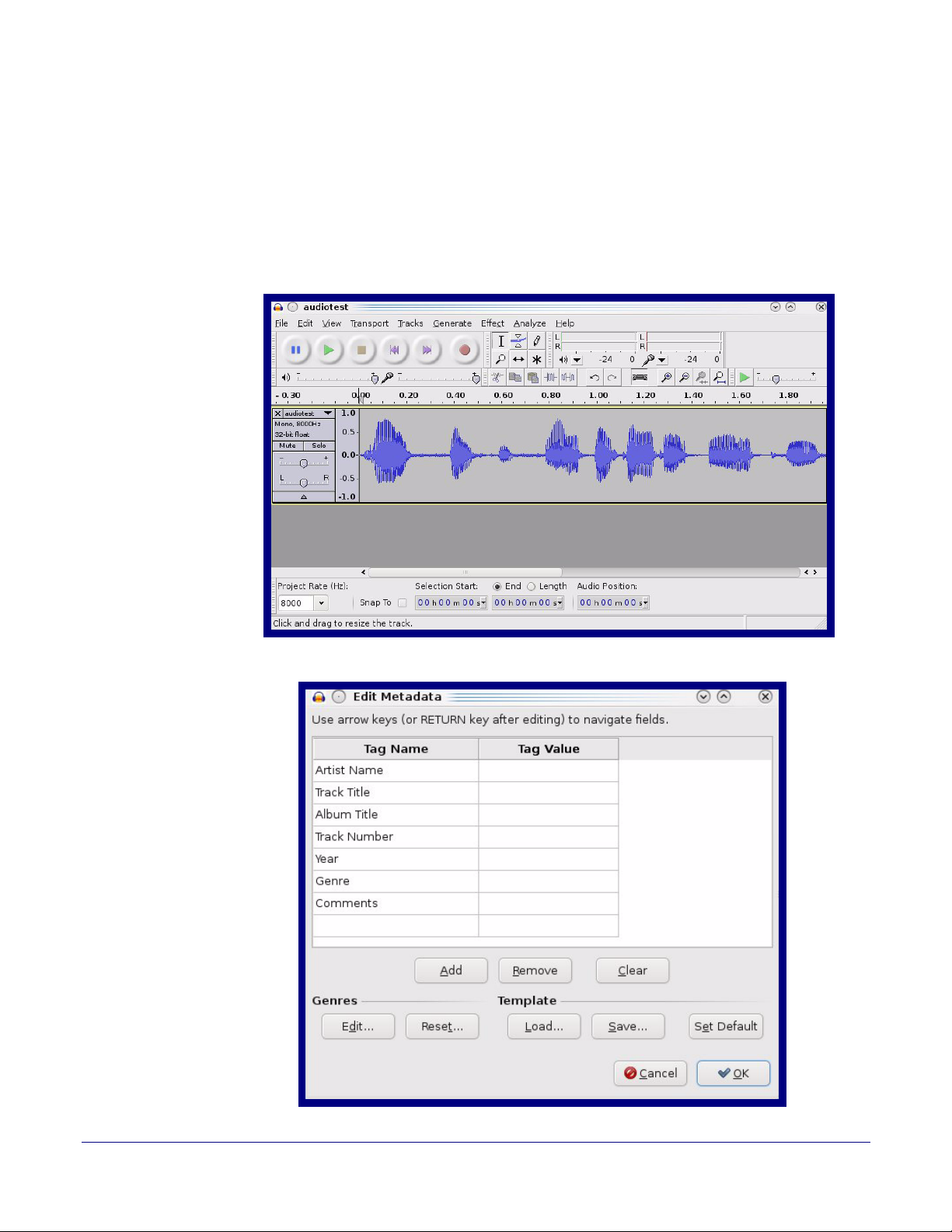
2.4.14.1 User-created Audio Files
User created audio files should be saved in the following format:
RIFF (little-endian) data, WAVE audio, Microsoft PCM, 16 bit, mono 8000 Hz
You can use the free utility Audacity to convert audio files into this format. See Figure 2-40 through
Figure 2-42.
Installing the Singlewire InformaCast Indoor Intercom with Keypad
Configure the Audio Configuration Parameters
Figure 2-40. Audacity 1
79
Figure 2-41. Audacity 2
Operations Guide 931640A CyberData Corporation
Page 87
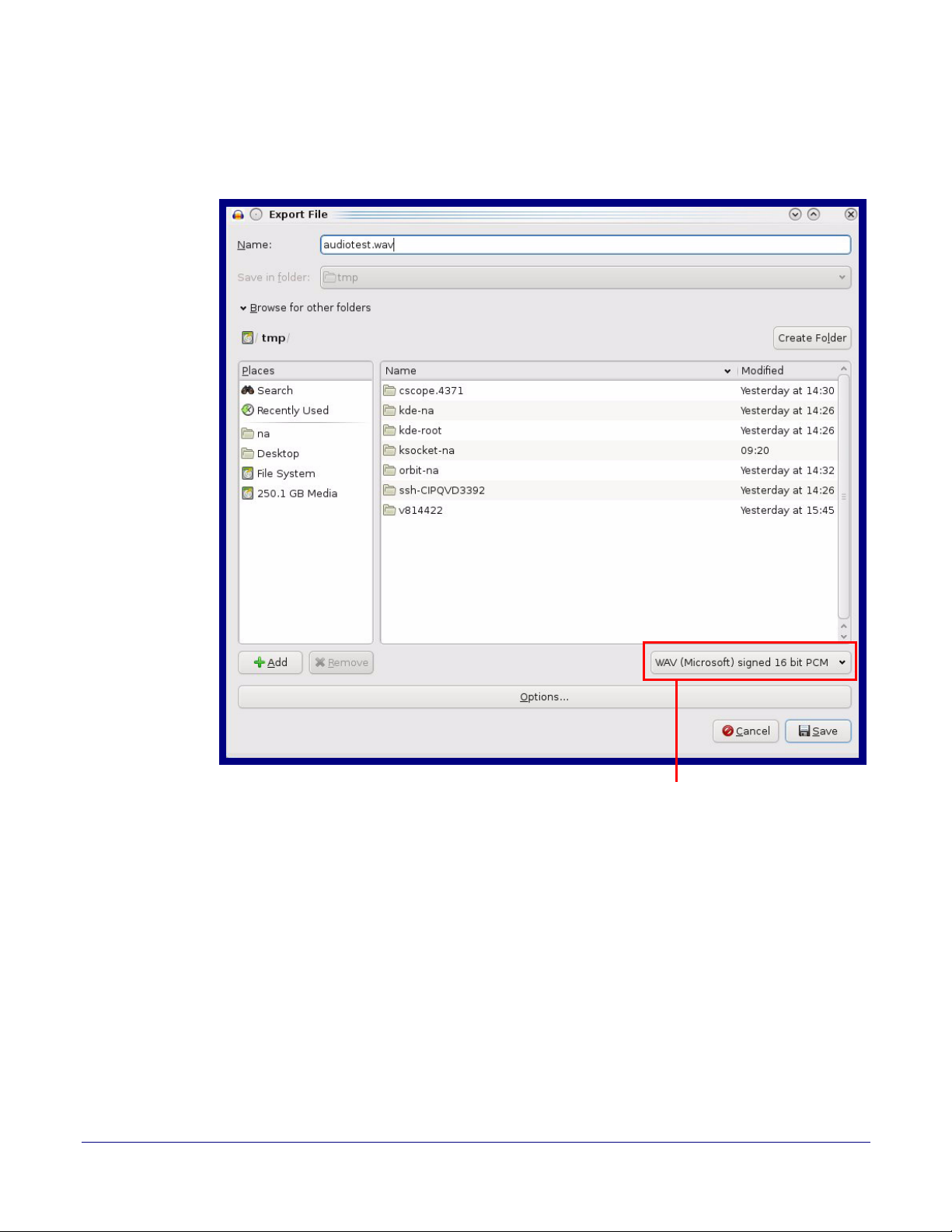
Installing the Singlewire InformaCast Indoor Intercom with Keypad
WAV (Microsoft) signed 16 bit PCM
Configure the Audio Configuration Parameters
When you export an audio file with Audacity, save the output as:
• WAV (Microsoft) signed 16 bit PCM.
Figure 2-42. WAV (Microsoft) signed 16 bit PCM
80
Operations Guide 931640A CyberData Corporation
Page 88
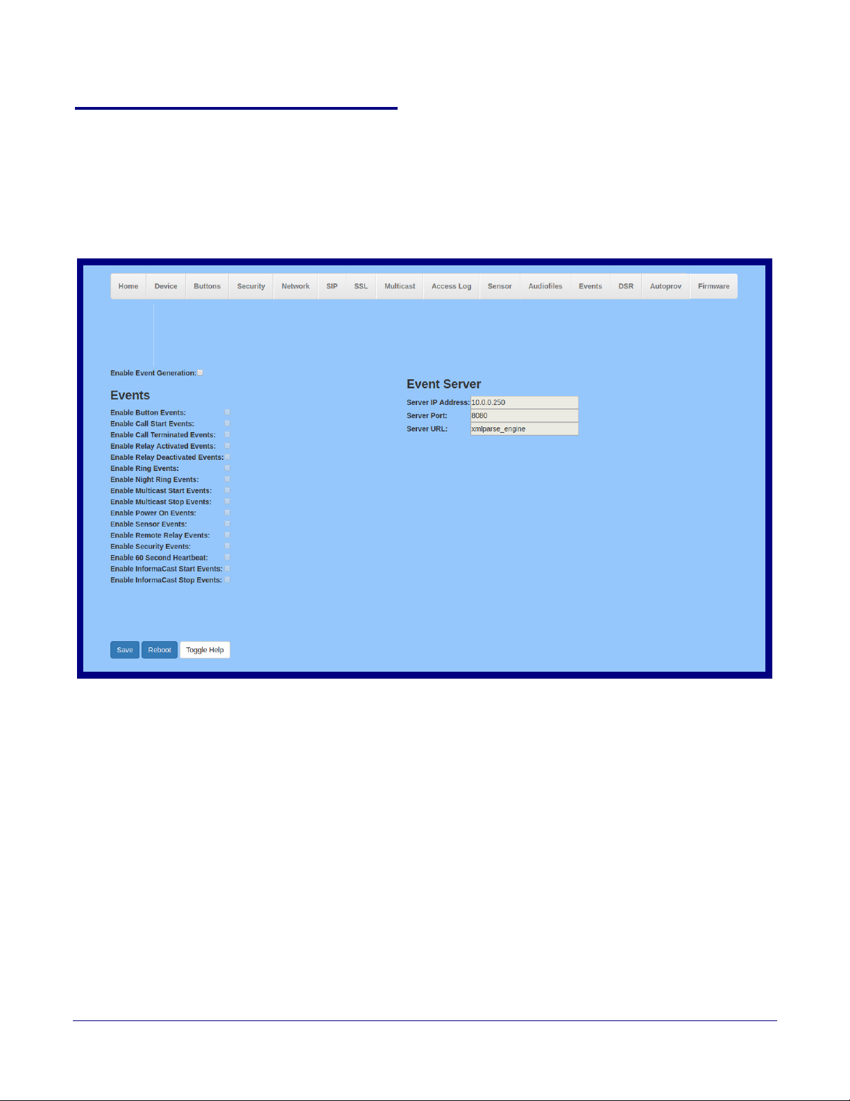
Installing the Singlewire InformaCast Indoor Intercom with Keypad
Singlewire Keypad Intercom
2.4.15 Configure the Events Parameters
The Events page specifies a remote server that can be used to receive HTTP POST events when
actions take place on the board.
1. Click on the Events menu button to open the Events page (Figure 2-43).
Figure 2-43. Event Configuration Page
Configure the Events Parameters
81
Operations Guide 931640A CyberData Corporation
Page 89

Installing the Singlewire InformaCast Indoor Intercom with Keypad
Configure the Events Parameters
2. On the Events page, enter values for the parameters indicated in Ta bl e 2-23.
82
Note The question mark icon (
after the To
ggle Help button is pressed.
) in the following table shows which web page items will be defined
Table 2-23. Events Configuration Parameters
Web Page Item Description
Enable Event Generation The device will send HTTP POST events to the specified remote server and port
number whenever a certain action takes place. Select an event type below to
generate an HTTP POST event.
Events
Enable Button Events When selected, the device will report Call button presses.
Enable Call Start Events
Enable Call Terminated Events
Enable Relay Activated Events
Enable Relay Deactivated Events
Enable Ring Events
When selected, the device will report the start of a SIP call.
When selected, the device will report the end of a SIP call.
When selected, the device will report relay activation.
When selected, the device will report relay deactivation.
When selected, the device will report when it starts ringing upon an incoming SIP
call. A Ring Event will not be generated when Auto-Answer Incoming Calls is
enabled on the Device page.
Enable Night Ring Events
When selected, the device will report when it starts ringing upon an incoming SIP
call to the Nightringer extension. As a reminder, the Nightringer extension always
rings upon an incoming SIP call and it is not possible to alter this behavior.
Enable Multicast Start Events
When selected, the device will report when the device starts playing a multicast
audio stream.
Enable Multicast Stop Events
When selected, the device will report when the device stops playing a multicast
audio stream.
Enable Power On Events
Enable Sensor Events
Enable Remote Relay Events
Enable Security Events
Enable 60 Second Heartbeat Events
When selected, the device will report when it boots.
When selected, the device will report when the on-board sensor is activated.
When selected, the device will report when the remote relay (DSR) is activated.
When enabled, the device will report when the intrusion sensor is activated.
When enabled, the device will report a Heartbeat event every 60 seconds. SIP
registration is not required to generate Heartbeat events.
Enable Informacast Start Events
When selected, the device will report when a Start event has been received from
the Singlewire server.
Enable Informacast Stop Events
When selected, the device will report when a Stop event has been received from
the Singlewire server.
Check All Click on Che
Uncheck All
Click on Uncheck All to de-select all of the events on the page.
ck All to select all of the events on the page.
Event Server
Server IP Address The IPv4 address of the event server in dotted decimal notation.
Server Port
Specify the event server port number. The supported range is 0-65536. Enter up to
5 digits.
Server URL
Generally, the destination URL is the name of the application that receives the
events and the string in the HTTP POST command. It can be a script used to parse
and process the HTTP POST events. Enter up to 127 characters.
Operations Guide 931640A CyberData Corporation
Page 90
Table 2-23. Events Configuration Parameters(continued)
Web Page Item Description
Click the Save button to save your configuration settings.
Click on the Reboot button to reboot the system.
Click on the Toggle Help button to see a short description of some of the web page
items. First click on the Toggle Help button, and you will see a question mark ( )
appear next to some of the web page items. Mo
a question mark to see a short description of a specific web page item.
2.4.15.1 Example Packets for Events
The server and port are used to point to the listening server and the 'Remote Event Server URL' is
the destination URL (typically the script running on the remote server that's used to parse and
process the POST events).
Installing the Singlewire InformaCast Indoor Intercom with Keypad
Configure the Events Parameters
ve the mouse pointer to hover over
83
Note The XML is
URL-encoded before transmission so the following examples are not completely
accurate.
Here are example packets for every event:
POST xmlparse_engine HTTP/1.1
Host: 10.0.3.79
User-Agent: CyberData/1.0.0
Content-Length: 197
Content-Type: application/x-www-form-urlencoded
<?xml version="1.0" encoding="ISO-8859-1"?>
<cyberdata NAME='CyberData VoIP Device' MAC='0020f70015b6'>
<event>POWERON</event>
</cyberdata>
POST xmlparse_engine HTTP/1.1
Host: 10.0.3.79
User-Agent: CyberData/1.0.0
Content-Length: 199
Content-Type: application/x-www-form-urlencoded
<?xml version="1.0" encoding="ISO-8859-1"?>
<cyberdata NAME='CyberData VoIP Device' MAC='0020f70015b6'>
<event>HEARTBEAT</event>
</cyberdata>
POST xmlparse_engine HTTP/1.1
Host: 10.0.3.79
User-Agent: CyberData/1.0.0
Content-Length: 196
Content-Type: application/x-www-form-urlencoded
Operations Guide 931640A CyberData Corporation
Page 91

Installing the Singlewire InformaCast Indoor Intercom with Keypad
Configure the Events Parameters
<?xml version="1.0" encoding="ISO-8859-1"?>
<cyberdata NAME='CyberData VoIP Device' MAC='0020f70015b6'>
<event>BUTTON</event>
</cyberdata>
POST xmlparse_engine HTTP/1.1
Host: 10.0.3.79
User-Agent: CyberData/1.0.0
Content-Length: 201
Content-Type: application/x-www-form-urlencoded
<?xml version="1.0" encoding="ISO-8859-1"?>
<cyberdata NAME='CyberData VoIP Device' MAC='0020f70015b6'>
<event>CALL_ACTIVE</event>
</cyberdata>
POST xmlparse_engine HTTP/1.1
Host: 10.0.3.79
User-Agent: CyberData/1.0.0
Content-Length: 205
Content-Type: application/x-www-form-urlencoded
<?xml version="1.0" encoding="ISO-8859-1"?>
<cyberdata NAME='CyberData VoIP Device' MAC='0020f70015b6'>
<event>CALL_TERMINATED</event>
</cyberdata>
84
POST xmlparse_engine HTTP/1.1
Host: 10.0.3.79
User-Agent: CyberData/1.0.0
Content-Length: 197
Content-Type: application/x-www-form-urlencoded
<?xml version="1.0" encoding="ISO-8859-1"?>
<cyberdata NAME='CyberData VoIP Device' MAC='0020f70015b6'>
<event>RINGING</event>
</cyberdata>
POST xmlparse_engine HTTP/1.1
Host: 10.0.3.79
User-Agent: CyberData/1.0.0
Content-Length: 234
Content-Type: application/x-www-form-urlencoded
<?xml version="1.0" encoding="ISO-8859-1"?>
<cyberdata NAME='CyberData VoIP Device' MAC='0020f70015b6'>
<event>MULTICAST_START</event>
<index>8</index>
</cyberdata>
POST xmlparse_engine HTTP/1.1
Host: 10.0.3.79
User-Agent: CyberData/1.0.0
Content-Length: 233
Content-Type: application/x-www-form-urlencoded
Operations Guide 931640A CyberData Corporation
Page 92

Installing the Singlewire InformaCast Indoor Intercom with Keypad
Configure the Events Parameters
<?xml version="1.0" encoding="ISO-8859-1"?>
<cyberdata NAME='CyberData VoIP Device' MAC='0020f70015b6'>
<event>MULTICAST_STOP</event>
<index>8</index>
</cyberdata>
POST xmlparse_engine HTTP/1.1
Host: 10.0.3.79
User-Agent: CyberData/1.0.0
Content-Length: 234
Content-Type: application/x-www-form-urlencoded
<?xml version="1.0" encoding="ISO-8859-1"?>
<cyberdata NAME='CyberData VoIP Device' MAC='0020f70015b6'>
<event>RELAY_ACTIVATED</event>
</cyberdata>
POST xmlparse_engine HTTP/1.1
Host: 10.0.3.79
User-Agent: CyberData/1.0.0
Content-Length: 234
Content-Type: application/x-www-form-urlencoded
<?xml version="1.0" encoding="ISO-8859-1"?>
<cyberdata NAME='CyberData VoIP Device' MAC='0020f70015b6'>
<event>RELAY_DEACTIVATED</event>
</cyberdata>
85
POST xmlparse_engine HTTP/1.1
Host: 10.0.3.79
User-Agent: CyberData/1.0.0
Content-Length: 234
Content-Type: application/x-www-form-urlencoded
<?xml version="1.0" encoding="ISO-8859-1"?>
<cyberdata NAME='CyberData VoIP Device' MAC='0020f70015b6'>
<event>NIGHTRINGING</event>
</cyberdata>
Operations Guide 931640A CyberData Corporation
Page 93
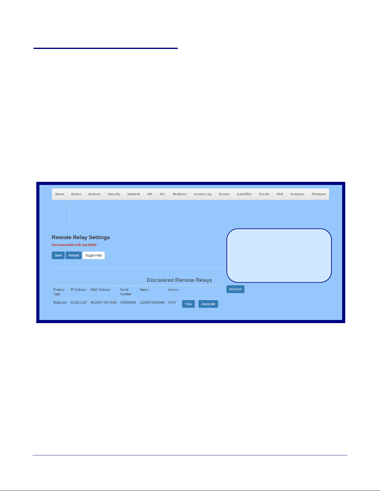
2.4.16 Configure the Door Strike Relay
Singlewire Keypad Intercom
This is the default page when the
device is not associated with any
DSRs
.
Please see the Dual Door
Strike Relay Operations Guide for
more settings and options on the
DSR page when the device is
associated with a DSR.
The Door Strike Relay (DSR) is a network device designed to control an electronic door strike. The
DSR is meant to be used as a replacement for (or an addition to) the on-board relay. In addition to
being a drop-in 12 Amp relay, the DSR can monitor and record when the door is open or closed.
The DSR can be configured to trigger in the following ways: on the entry of a DTMF code, manually
through the web interface, or by using a Windows application.
This section describes operations for running firmware version 4.8 or later of the Dual Door Strike
Relay. If you have an older version of the firmware, then please contact CyberData Technical
Support. The version number appears in the
(Figure 2-44).
1. Click on the DSR menu button to open the DSR page (Figure 2-44).
Figure 2-44. DSR Page (not associated with any DSRs)
Installing the Singlewire InformaCast Indoor Intercom with Keypad
Configure the Door Strike Relay
Discovered Remote Relays section on the DSR page
86
Operations Guide 931640A CyberData Corporation
Page 94
Installing the Singlewire InformaCast Indoor Intercom with Keypad
Configure the Door Strike Relay
2. On the DSR page, enter values for the parameters indicated in Ta bl e 2-24.
87
Note The question mark icon (
after the To
ggle Help button is pressed.
) in the following table shows which web page items will be defined
Table 2-24. DSR Configuration Parameters (not associated with any DSRs)
Web Page Item Description
Remote Relay Settings The settings in this section will activate an associated door strike relay. If a door
strike relay is not associated with the device, then you will only see the words Not
associated with any DSRs.
Click the Save button to save your configuration settings.
Click on the Reboot button to reboot the system.
Click on the Toggle Help button to see a short description of some of the web page
items. First click on the Toggle Help button, and you will see a question mark ( )
appear next to some of the web page items. Move the mouse pointer to hover over a
question mark to see a short description of a specific web page item.
Discovered Remote Relays The Discovered Remote Relays section lists all of the networked door strike relays
on the network. To associate your device with a door strike relay, click on the
Associate button. This action allows the user to configure the door strike relay. Keep
in mind that a device may only be associated with one door strike relay.
Product Type Displays the product type of the remote relay.
IP Address Displays the IP address of the remote relay.
MAC Address Displays the MAC address of the remote relay.
Serial Number Displays the serial number of the remote relay.
Name Displays the name of the remote relay.
Version Displays the version of the remote relay.
Use this button to search for and find any remote relays that are available on the
network.
Use this button to view the settings of a remote relay that has been “discovered” after
pressing the Discover button.
Use this button to associate the remote relay with the device. Only one relay may be
associated with a device.
Use this button to disassociate the remote relay from the device. Only one relay may
be associated with a device. This button is only available when a relay is associated
with a device.
Note Associating a DSR does not require a reboot. However, you should reboot the device after
disassociating a DSR.
Note Wh
ile in Security Mode, the 011375 Network Dual Door Strike Relay will operate only in
Automatic Mode.
Operations Guide 931640A CyberData Corporation
Page 95
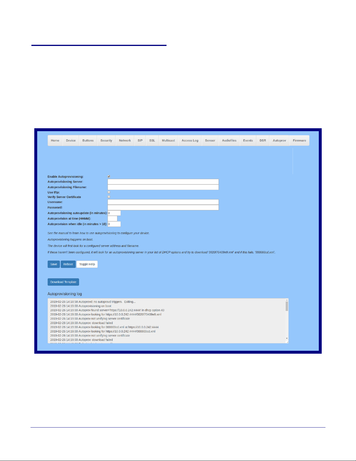
Installing the Singlewire InformaCast Indoor Intercom with Keypad
Singlewire Keypad Intercom
2.4.17 Configure the Autoprovisioning Parameters
Autoprovisioning can be used to automatically configure your device. The autoprovisioning file is an
xml file with the device configuration. Values found in this file will override values stored in on-board
memory.
Note By default, the device will try to set up its configuration with autoprovisioning.
1. Click the Autoprov menu button to open the Autoprovisioning page. See Figure 2-45.
Figure 2-45. Autoprovisioning Page
Configure the Autoprovisioning Parameters
88
Operations Guide 931640A CyberData Corporation
Page 96
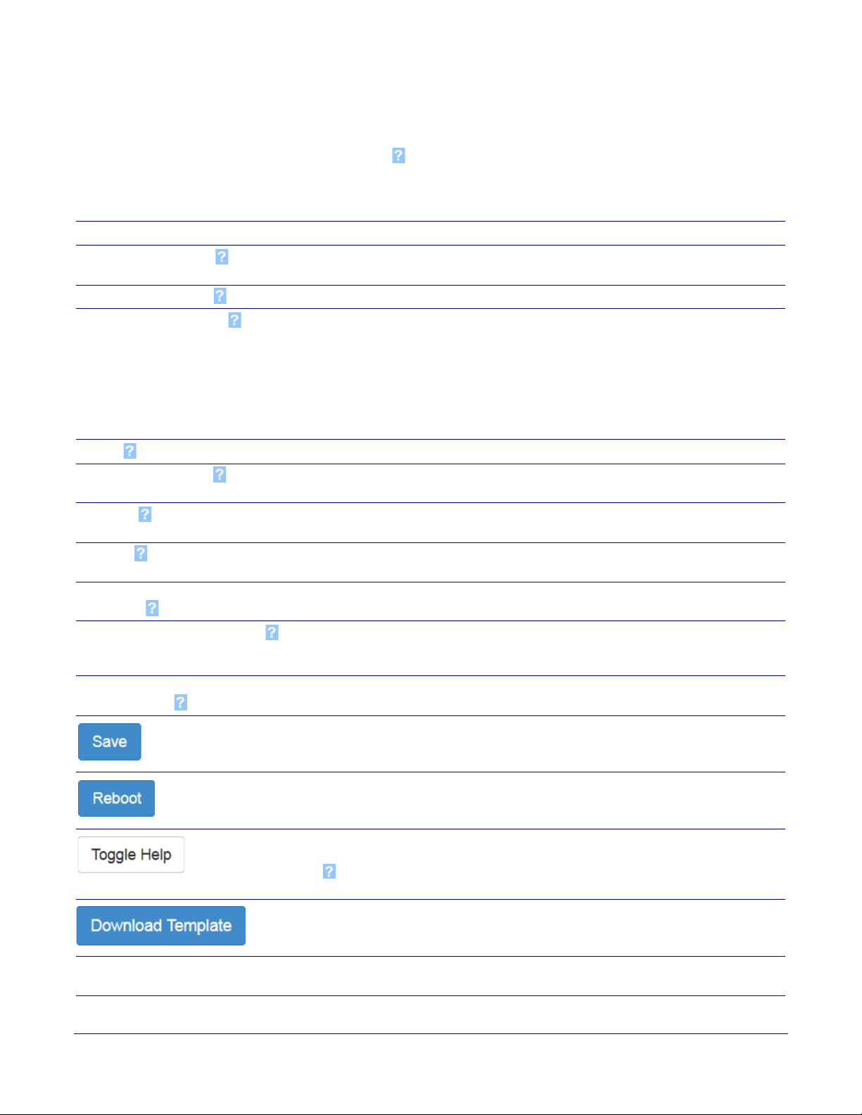
Installing the Singlewire InformaCast Indoor Intercom with Keypad
Configure the Autoprovisioning Parameters
2. On the Autoprovisioning page, you may enter values for the parameters indicated in Tab l e 2-
25.
89
Note The question mark icon (
after the To
ggle Help button is pressed.
) in the following table shows which web page items will be defined
Table 2-25. Autoprovisioning Page Parameters
Web Page Item Description
Enable Autoprovisioning The device will automatically fetch a configuration file, also known as the
'autoprovisioning file', based on the configured settings below.
Autoprovisioning Server
Autoprovisioning Filename
Enter the IPv4 address of the provisioning server in dotted decimal notation.
The autoprovisioning filename is the configuration filename. The default
autoprovisioning filename is in the format of <mac address>.xml.
Supported filename extensions are .txt, and .xml. The current filename is denoted
by an asterisk at the bottom of the Autoprovisioning Page. Enter up to 256
characters.
A file may have any name with an xml extension. If a file name is entered, the
device will look for the specified file name, and only that file.
Use tftp
Verify Server Certificate
The device will use TFTP (instead of http) to download autoprovisioning files.
When using ssl to download autoprovisioning files, reject connections where the
server address doesn't match the server certificate's common name.
Username
The username used to authenticate with an autoprovisioning server. Leave this
field blank to disable authentication.
Password
The password used to authenticate with an autoprovisioning server. Leave this field
blank to disable authentication.
Autoprovisioning Autoupdate
(in minutes)
Autoprovision at time (HHMMSS)
The reoccurring time (in minutes) the device will wait before checking for new
autoprovisioning files. Enter up to 6 digits. A value of 0 will disable this option.
The time of day the device will check for a new autoprovisioning file. The time must
be 6 characters in length and in HHMMSS format. An empty value will disable this
option.
Autoprovision when idle
(in minutes > 10)
The idle time (in minutes greater than 10) after which the device will check for a
new autoprovisioning file. Enter up to 6 digits. A value of 0 will disable this option.
Click the Sa
Click on the Re
Click on the T
ve button to save your configuration settings.
boot button to reboot the system.
oggle Help button to see a short description of some of the web
page items. First click on the Toggle Help button, and you will see a question mark
) appear next to some of the web page items. Move the mouse pointer to hover
(
over a question mark to see a short description of a specific web page item.
Press the Do
wnload Template button to create an autoprovisioning file for the
device. See Section 2.4.17.3, "Download Template Button"
Autoprovisioning log The autoprovisioning log provides informatio
n about the latest autoprovisioning
attempt (i.e. dhcp options and server accessed and files parsed or not found).
Operations Guide 931640A CyberData Corporation
Page 97

Note You must click on the Save button for the changes to take effect.
2.4.17.1 Autoprovisioning
On boot, the device will look for an autoprovisioning server configured on the Autoprovisioning Page
or specified as a DHCP option. When it finds a server, it will try to download the following (in order of
preference):
1. The file configured on the autoprovisioning page.
2. A file named according to it's mac address (for example: 0020f7350058.xml).
3. The file 000000cd.xml
The file can be hosted using a standard web server (like apache, IIS, or nginx), and the device can
download over SSL. The file server can be an ipv4 address in dotted decimal notation or a fully
qualified domain name.
By default, the device will get its autoprovisioning server from the DHCP options. See Section
2.4.17.2, "Sample dhcpd.conf" for an example of how to configure dhcpd to offer autoprovisioning
server addresses. If multiple options are set, the device will attempt to download autoprovisioning
files from every server.
Installing the Singlewire InformaCast Indoor Intercom with Keypad
Configure the Autoprovisioning Parameters
90
The DHCP option determines the protocol used to download the autoprovisioning file. The device
looks for DHCP options in the following order:
1. Option 43 - a FQDN or an IP address to an http server
2. Option 72 - an IP address to an http server
3. Option 150 - an IP address to a tftp server
4. Option 66 - an IP address to a tftp server or if the entry starts with 'http', a FQDN to a http server.
You can download an autoprovisioning template file from the Autoprovisioning Page using the
Download Template button (see Ta bl e 2-25). This file contains every configuration option that can
be set on the board.
Autoprovisioning files can contain the whole configuration or a subset of this file. The first
autoprovisioning file can also contain links to other autoprovisioning files.
The <MiscSettings> section contains some examples of additional autoprovisioning files:
<MiscSettings>
<DeviceName>CyberData VoIP Device</DeviceName>
<!-- <AutoprovFile>common.xml</AutoprovFile>-->
<!-- <AutoprovFile>sip_reg[macaddress].xml</AutoprovFile>-->
<!-- <AutoprovFile>audio[macaddress]</AutoprovFile>-->
<!-- <AutoprovFile>device[macaddress].xml</AutoprovFile>-->
</MiscSettings>
After downloading the first autoprovisioning file, the device will step through up to twenty additional
<AutoprovFile> entries and try to download these files from the same server.
When the device finds a filename with the string [macaddress], it will replace this string with the
mac address.
Operations Guide 931640A CyberData Corporation
Page 98

Installing the Singlewire InformaCast Indoor Intercom with Keypad
Configure the Autoprovisioning Parameters
As an example, the user has configured option 43 on their DHCP server to “http://example.com,” and
on their server, they have a file named 0020f7123456.xml (the same as the mac address of the
device).
The file 0020f7123456.xml contains:
<?xml version="1.0" encoding="utf-8" ?>
<specific>
<MiscSettings>
<DeviceName>Newname</DeviceName>
<AutoprovFile>common.xml</AutoprovFile>
<AutoprovFile>sip_reg[macaddress].xml</AutoprovFile>
<AutoprovFile>audio[macaddress]</AutoprovFile>
<AutoprovFile>device.xml</AutoprovFile>
</MiscSettings>
</specific>
1. The device will first set it's name to 'Newname'.
2. It will try to download http://example.com/common.xml.
3. It will try to download http://example.com/sip_reg0020f7123456.xml.
4. It will try to download http://example.com/audio0020f7123456.
91
Checking for New Autoprovisioning Files after Boot
5. It will try to download http://example.com/device.xml.
The device is reconfigured every time it downloads a new file so if two files configure the same
option the last one will be the one that is saved.
It is possible to autoprovision autoprovisioning values (for example, to disable autoprovisioning or to
configure a time to check for new files).
The device will always check for an autoprovisioning files on boot but it can be configured to also
check after a periodic delay, when idle, or at a specified time. When one of these options is set, the
device will download its autoprovisioning files again, and if it finds any differences from the files it
downloaded on boot, it will force a reboot and reconfigure.
Operations Guide 931640A CyberData Corporation
Page 99

Installing the Singlewire InformaCast Indoor Intercom with Keypad
Configure the Autoprovisioning Parameters
92
The Autoprovisioning Filename
The autoprovisioning filename can contain a file, a file path, or a directory.
Table 2-26. Autoprovisioning File Name
Autoprovisioning
Filename
config.xml
/path/to/config.xml
subdirectory/path/ 10.0.1.3 10.0.1.3/subdirectory/path/0020f7020002.xml
Autoprovisioning
File Downloaded
Server
10.0.1.3 10.0.1.3/config.xml
10.0.1.3 10.0.1.3/path/to/config.xml
TFTP options may not support subdirectories. If a directory is set in the filename field, firmware and
udio files will also be downloaded from this subdirectory.
a
If the filename ends with a forward slash “/,” the device will treat it as a subdirectory.
For example:
The autoprovisioning server is set to “https://www.example.com”
The autoprovisioning filename is set to “cyberdata/”
On boot, the device will try to download:
https://www.example.com/cyberdata/0020f7123456.xml
...and if this fails:
https://www.example.com/cyberdata/000000cd.xml
Audio files and firmware files will also add “cyberdata” to the URL before downloading.
Operations Guide 931640A CyberData Corporation
Page 100

Installing the Singlewire InformaCast Indoor Intercom with Keypad
Configure the Autoprovisioning Parameters
93
Autoprovisioning Firmware Updates
<FirmwareSettings>
<FirmwareFile>505-uImage-ceilingspeaker</FirmwareFile>
<FirmwareServer>10.0.1.3</FirmwareServer>
<OutdoorIntercom30>firmware_file_v9.3.0</OutdoorIntercom30>
<OutdoorIntercom31>firmware_file_v10.3.0</OutdoorIntercom31>
<CallButton31>firmware_file_v10.3.0</CallButton31>
</FirmwareSettings>
In the <FirmwareSettings> section, the <FirmwareServer> element can be used to specify a
different server for hosting firmware files. When this element is not available, the device will try to
download the file from the autoprovisioning server.
The device will use the filename to determine when to autoprovision firmware updates. The default
configuration is blank, so the first time you set a value in your autoprovisioning file, it may force a
firmware update even if the firmware version has not changed.
The <FirmwareFile> name can contain path elements (i.e. /path/to/firmware/10.3.0-uImage[device_file_name]).
The device also supports product strings for downloading firmware. If the <FirmwareFile> option is
not set, the device will look for its particular product string for a firmware filename. In this way, a
generic autoprovisioning file can specify unique firmware for a range of products.
The list of valid product strings:
<ProductString>CallButton31</ProductString>
<ProductString>EmergencyIntercom31</ProductString>
<ProductString>EmergencyIntercom31SW</ProductString>
<ProductString>IndoorIntercom31</ProductString>
<ProductString>IndoorIntercom31SW</ProductString>
<ProductString>IndoorKeypad31</ProductString>
<ProductString>IndoorKeypad31SW</ProductString>
<ProductString>OfficeRinger31</ProductString>
<ProductString>OfficeRinger31SW</ProductString>
<ProductString>OutdoorIntercom31</ProductString>
<ProductString>OutdoorIntercom31SW</ProductString>
<ProductString>OutdoorKeypad31</ProductString>
<ProductString>OutdoorKeypad31SW</ProductString>
<ProductString>Strobe31</ProductString>
<ProductString>Strobe31SW</ProductString>
Operations Guide 931640A CyberData Corporation
 Loading...