

CyberData 011146 Operation Manual

VoIP Paging Server
The IP Endpoint Company
Operations Guide
for Firmware Version 11.3.0
SIP Compliant
Part #011146
Document Part #931073B
CyberData Corporation
3 Justin Court
Monterey, CA 93940
(831) 373-2601

Operations Guide 931073B
Technical Support
The fastest way to get technical support for your VoIP product is to
submit a VoIP Technical Support form at the following website:
http://support.cyberdata.net/
Phone: (831) 373-2601, Ext. 333
Email: support@cyberdata.net
Fax: (831) 373-4193
Company and product information is at www.cyberdata.net.
The IP Endpoint Company
SIP Compliant 011146
COPYRIGHT NOTICE:
© 2015, CyberData Corporation, ALL RIGHTS RESERVED.
This manual and related materials are the copyrighted property of CyberData Corporation. No part of
this manual or related materials may be reproduced or transmitted, in any form or by any means
(except for internal use by licensed customers), without prior express written permission of
CyberData Corporation. This manual, and the products, software, firmware, and/or hardware
described in this manual are the property of CyberData Corporation, provided under the terms of an
agreement between CyberData Corporation and recipient of this manual, and their use is subject to
that agreement and its terms.
DISCLAIMER: Except as expressly and specifically stated in a written agreement executed by
CyberData Corporation, CyberData Corporation makes no representation or warranty, express or
implied, including any warranty or merchantability or fitness for any purpose, with respect to this
manual or the products, software, firmware, and/or hardware described herein, and CyberData
Corporation assumes no liability for damages or claims resulting from any use of this manual or such
products, software, firmware, and/or hardware. CyberData Corporation reserves the right to make
changes, without notice, to this manual and to any such product, software, firmware, and/or
hardware.
OPEN SOURCE STATEMENT: Certain software components included in CyberData products are
subject to the GNU General Public License (GPL) and Lesser GNU General Public License (LGPL)
“open source” or “free software” licenses. Some of this Open Source Software may be owned by third
parties. Open Source Software is not subject to the terms and conditions of the CyberData
COPYRIGHT NOTICE or software licenses. Your right to copy, modify, and distribute any Open
Source Software is determined by the terms of the GPL, LGPL, or third party, according to who
licenses that software.
CyberData Corporation 931073B Operations Guide
Software or firmware developed by Cyberdata that is unrelated to Open Source Software is
copyrighted by CyberData, subject to the terms of CyberData licenses, and may not be copied,
modified, reverse-engineered, or otherwise altered without explicit written permission from
CyberData Corporation.
TRADEMARK NOTICE: CyberData Corporation and the CyberData Corporation logos are
trademarks of CyberData Corporation. Other product names, trademarks, and service marks may be
the trademarks or registered trademarks of their respective owners.

Revision Information
Revision 931073B, which corresponds to firmware version 11.3.0, was released on August 5, 2015,
and has the following changes:
• Removes the following wget command from Ta b le 2-20, "Command Interface Post
Commands":
Trigger the Fault Detection Test (Fault Detection page)
wget --user admin --password admin --auth-no-challenge --no-check-certificate --quiet -O /
dev/null "https://10.0.3.71/cgi- bin/sensorconfig.cgi" --post-data "intrusiontest=yes"
Browsers Supported
The following browsers have been tested against firmware version 11.3.0:
• Internet Explorer (version: 10)
• Firefox (also called Mozilla Firefox) (version: 23.0.1 and 25.0)
• Chrome (version: 29.0.1547.66 m)
• Safari (version: 5.1.7)
CyberData Corporation 931073B Operations Guide
Pictorial Alert Icons
GENERAL ALERT
Hazard Levels
Danger: Indicates an imminently hazardous situation which, if not avoided, will result in death or
serious injury. This is limited to the most extreme situations.
Warning: Indicates a potentially hazardous situation which, if not avoided, could result in death or
ser
ious injury.
General Alert
This pictoral alert indicates a potentially hazardous situation. This alert will be
followed by a hazard level heading and more specific information about the
hazard.
Ground
This pictoral alert indicates the Earth grounding connection point.
Caution: Indicates a potentially hazardous situation which, if not a
moderate injury. It may also alert users against unsafe practices.
Notice: Indicates a statement of company policy (tha
The safety guidelines for the equipment in this manual do not purport to address all the safety issues
he equipment. It is the responsibility of the user to establish appropriate safety, ergonomic, and
of t
health practices and determine the applicability of regulatory limitations prior to use. Potential safety
hazards are identified in this manual through the use of words Danger, Warning, and Caution, the
specific hazard type, and pictorial alert icons.
t is, a safety policy or protection of property).
voided, could result in minor or
CyberData Corporation 931073B Operations Guide
Important Safety Instructions
GENERAL ALERT
GENERAL ALERT
GENERAL ALERT
1. Read these instructions.
2. Keep these instructions.
3. Heed all warnings.
4. Follow all instructions.
5. Do not use this apparatus near water.
6. Clean only with dry cloth.
7. Do not block any ventilation openings. Install in accordance with the manufacturer’s instructions.
8. Do not install near any heat sources such as radiators, heat registers, stoves, or other apparatus
(includin
9. Do not defeat the safety purpose of the polarized or grounding-type plug. A polarized plug has
tw
grounding prong. The wide blade or the third prong are provided for your safety. If the provided
plug does not fit into your outlet, consult an electrician for replacement of the obsolete outlet.
10. Protect the power cord from being walked on or pinched particularly at plugs, convenience
receptacles
g amplifiers) that produce heat.
o blades with one wider than the other. A grounding type plug has two blades and a third
, and the point where they exit from the apparatus.
11. Only use attachments/accessories specified by the manufacturer.
12. Refer all servicing to qualified service personnel. Servicing is required when the apparatus has
een damaged in any way, such as power-supply cord or plug is damaged, liquid has been
b
spilled or objects have fallen into the apparatus, the apparatus has been exposed to rain or
moisture, does not operate normally, or has been dropped.
13. Prior to installation, consult local building and electrical code requirements.
Warnin g
Electrical Hazard:
according to all local electrical and building codes.
This product should be installed by a licensed electrician
Warnin g
Electrical Hazard:
the floor/wall
To prevent injury, this apparatus must be securely attached to
in accordance with the installation instructions.
Warnin g
The PoE connector is intended for intra-building connections only and does not
rout
e to the outside plant.
CyberData Corporation 931073B Operations Guide

Abbreviations and Terms
Abbreviation or Term Definition
A-law A standard companding algorithm, used in European digital
communications systems to optimize, i.e., modify, the dynamic range of an
analog signal for digitizing.
AVP Audio Video Profile
Cat 5 TIA/EIA-568-B Ca
DHCP Dynamic Host Configuration Protocol
LAN Local Area Network
LED Light Emitting Diode
Mbps Megabits per second.
NTP Network Time Protocol
PBX Private Branch Exchange
PoE Power over Ethernet (as per IEEE 802.3af standard)
RTFM Reset Test Function Management
SIP Session Initiated Protocol
u-law A companding algorithm, primarily used in the digital telecommunication
UC Unified Communications
VoIP Voice over Internet Protocol
tegory 5
CyberData Corporation 931073B Operations Guide

Contents
Chapter 1 Product Overview 1
1.1 How to Identify This Product .....................................................................................................2
1.2 Product features .......................................................................................................................3
1.3 Product Specifications ..............................................................................................................4
Chapter 2 Setting Up the Paging Server 5
2.1 Parts List ..................................................................................................................................5
2.2 Typical Installation ....................................................................................................................6
2.3 Connecting the Paging Server ..................................................................................................7
2.4 Configuring the Paging Server ..............................................................................................14
i
2.3.1 Ground Connection ........................................................................................................7
2.3.2 Line In ............................................................................................................................7
2.3.3 Line Out ..........................................................................................................................7
2.3.4 Page Port Output Connections .......................................................................................8
Pin 1 and 2—Fault Sense Input (Common/Sense) ..........................................................8
Pin 3, 4, and 5—Positive/Negative 600-Ohm Audio Output/Audio Ground Reference .....8
Pin 6 and 7—Relay Contact (Common/Normally Open) ..................................................8
2.3.5 Removable Interface Connector .....................................................................................9
2.3.6 Connect to the Power Source ......................................................................................10
Poe .................................................................................................................................10
Non-Poe .........................................................................................................................10
Chassis Ground ..............................................................................................................10
2.3.7 Connect to the Network ...............................................................................................11
2.3.8 Confirm that the Paging Server is Up and Running ....................................................12
Confirm Power on, Network Connectivity, and Connection Speed ................................12
Verify Network Activity ...................................................................................................12
2.3.9 Announcing the IP Address ..........................................................................................13
2.3.10 Restore the Factory Default Settings .........................................................................13
2.4.1 Gather the Required Configuration Information ..........................................................14
Static or DHCP Addressing? .........................................................................................14
Username and Password for Configuration GUI ...........................................................14
SIP Settings ...................................................................................................................14
2.4.2 Paging Server Web Page Navigation ...........................................................................15
2.4.3 Using the Toggle Help Button .......................................................................................16
2.4.4 Log in to the Configuration GUI ...................................................................................18
2.4.5 Configure the Device Parameters ................................................................................22
Polycom Paging ..............................................................................................................24
Time Zone Strings ..........................................................................................................26
2.4.6 Configure the Network Parameters .............................................................................29
2.4.7 Configure the SIP Parameters .....................................................................................32
Point-to-Point Configuration ............................................................................................37
2.4.8 Configure the Paging Groups (PGROUPS) Parameters ..............................................38
2.4.9 Operating the Paging Server ........................................................................................44
DTMF Bypassed .............................................................................................................44
DTMF Not Bypassed ......................................................................................................44
2.4.10 Configure the Fault Detection Parameters .................................................................45
2.4.11 Configure the Audio Parameters ................................................................................47
User-created Audio Files ................................................................................................50
2.4.12 Configure the Event Parameters ................................................................................53
Example Packets for Events ...........................................................................................55
2.4.13 Configure the Autoprovisioning Parameters ...............................................................58
CyberData Corporation 931073B Operations Guide

Autoprovisioning .............................................................................................................60
Sample dhcpd.conf .........................................................................................................68
Get Autoprovisioning Template Button ...........................................................................69
2.5 Upgrading the Firmware .........................................................................................................70
2.5.1 Upgrade the Firmware ..................................................................................................70
2.5.2 Reboot the Paging Server ............................................................................................72
2.6.1 Command Interface Post Commands ..........................................................................73
Appendix A Setting Up a TFTP Server 77
A.1 Set up a TFTP Server ............................................................................................................77
A.1.1 In a LINUX Environment ..............................................................................................77
A.1.2 In a Windows Environment .........................................................................................77
Appendix B Troubleshooting/Technical Support 78
B.1 Frequently Asked Questions (FAQ) ........................................................................................78
B.2 Documentation .......................................................................................................................78
B.3 Contact Information ................................................................................................................79
B.4 Warranty .................................................................................................................................80
B.4.1 Warranty & RMA Returns within the United States ......................................................80
B.4.2 Warranty & RMA Returns outside of the United States ...............................................80
B.4.3 Spare in the Air Policy ..................................................................................................81
B.4.4 Return and Restocking Policy ......................................................................................81
B.4.5 Warranty and RMA Returns Page ................................................................................81
ii
CyberData Corporation 931073B Operations Guide

1 Product Overview
The CyberData V3 VoIP Paging Server enables users through a single SIP phone extension, to
access multiple zones for paging in a VoIP network and to connect to legacy analog overhead
paging systems.
A second SIP extension can be configured as a night ringer playing a user-uploadable audio file.
The V3 Paging Server allows direct connection to legacy analog paging amplifiers that require a
"Page Port" type of input that meets a balanced 600 Ohm 10Vpp signal or a 10k Ohm Hi-Z 2vpp
signal. You can also take advantage of connections for a dry contact relay (page start output) and
sense input (Fault Sense Input) for additional functionality.
The easy-to-use, web-based configuration provides a graphical user interface to set up to 100
paging zones for IP paging with unique multicast address and port number combinations.
The V3 Paging Server connects via a single CAT 5 or 6 network cable to a standard PoE 802.3af
compliant switch.
1
CyberData Corporation 931073B Operations Guide
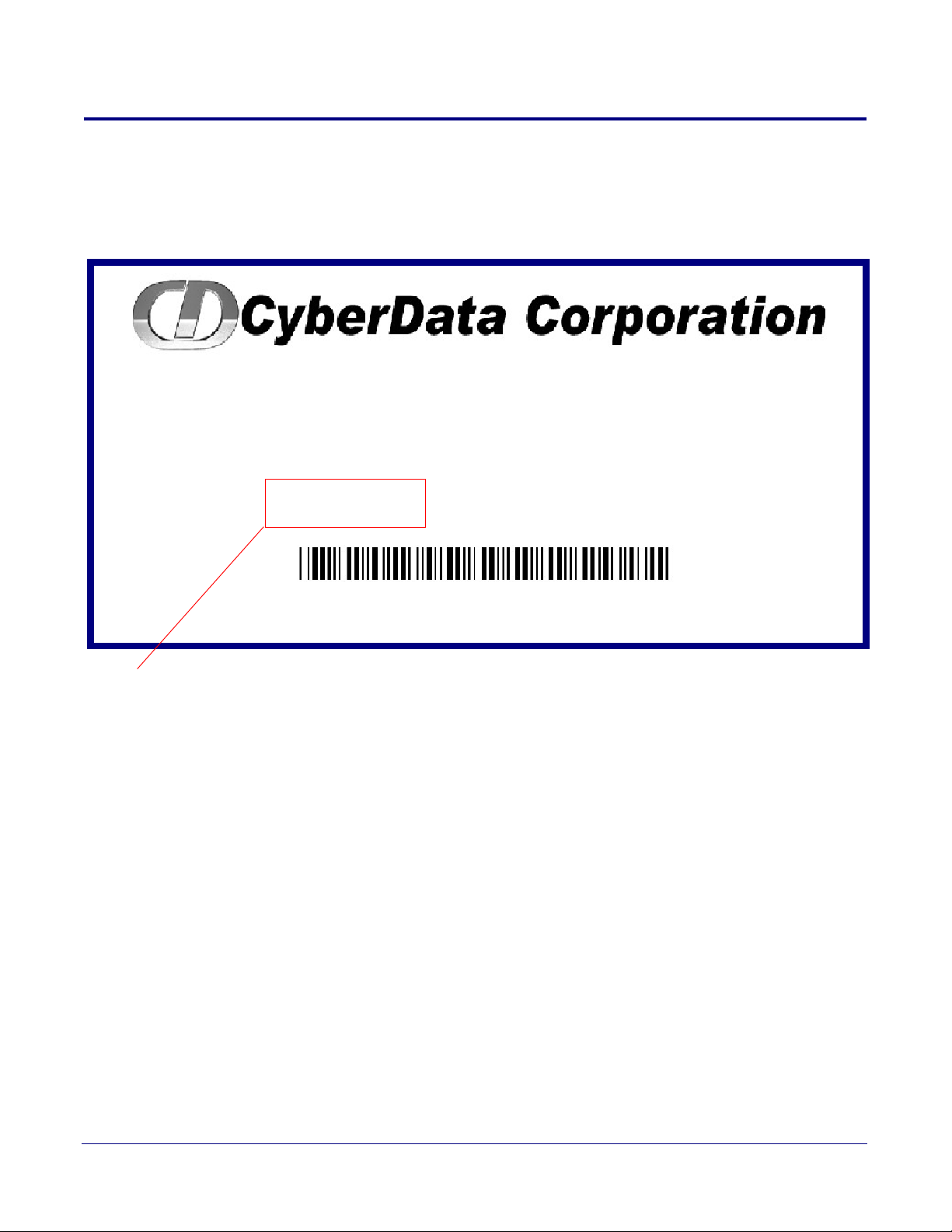
1.1 How to Identify This Product
V3 VoIP PAGING SERVER
RoHS COMPLIANT
011146C / 021059H
Model number
WWW.CYBERDATA.NET
146000001
To identify the VoIP Paging Server, look for a model number label similar to the one shown in Figure
1-1. The model number on the label should be 011146.
Figure 1-1. Model Number Label
Product Overview
How to Identify This Product
2
CyberData Corporation 931073B Operations Guide

1.2 Product features
● SIP RFC 3261
● Two SIP endpoints (one for Night Ringer)
● Multicast output
● Polycom group paging
● DTMF control of zone selection (with optional security code per zone)
● RTP Version 2 Multicast and Unicast
● Delayed page support
● Line-In connection for background music multicasting
● Line-out connection to support analog Amps
● Audio Codecs
• G.711 U-law
• G.711 A-law
• Speex
• DTMF detection (via RFC 2833)
● Cisco SRST support
● 802.11Q VLAN support
● Ability to import and export configuration
● Autoprovisioning
● Added support for NTP server for time keeping
• TFTP or HTTP
• Update at certain times of day
• Update after a certain amount of idle time
● HTTP command interface
● Outbound proxy support for night ringer
● Option to disable rport discovery
● DTMF tones can be played out of analog ports during a page
● User-configurable DTMF duration option
● Option to enable line-in audio to multicast on fault detection
● Remote amp fault sensor
● Web-based configuration and firmware upload
● User uploadable audio files
● PoE 802.3af enabled (Power-over-Ethernet)
● 19-inch rack mount option
Product Overview
Product features
3
CyberData Corporation 931073B Operations Guide

1.3 Product Specifications
Table 1-1. Product Specifications
Specifications
ower Requirement PoE or 48V DC
P
Connection Speed 10/100 Mbps
Protocol SIP compliant
Page Port Output Balanced 600 Ohm 5VPP
Line In:
Input Signal Amplitudes
Input Impedance
Line Out:
Output Signal Amplitudes
Output Level
Total Harmonic Distortion
Output Impedance
Part Number 011146
Dimensions 6.11” L x 4.05” W x 1.15” H
2.0 VPP maximum
10k Ohm
2.0 VPP maximum
+2dBm nominal
0.5% maximum
10k Ohm
Product Overview
Product Specifications
4
Weight 1.2 pounds
CyberData Corporation 931073B Operations Guide

2 Setting Up the Paging Server
The topics in this chapter provide information on setting up, configuring, and using the VoIP Paging
Server.
2.1 Parts List
The packaging for the Paging Server includes the parts in Ta b le 2-2.
Table 2-2. Parts List
Quantity Part Name Illustration
1 Paging Server
1 Installation Quick Reference Guide
5
1 Mounting Template (located on the last
of the Installation Quick
page
Reference)
1 Mounting Kit (part #070057A)
which includes:
(2) #4-6 x 7/8" Mo
(2) #4 x 1-1/4" Round Phillips Wood
Sc
rews
unting Anchors
CyberData Corporation 931073B Operations Guide
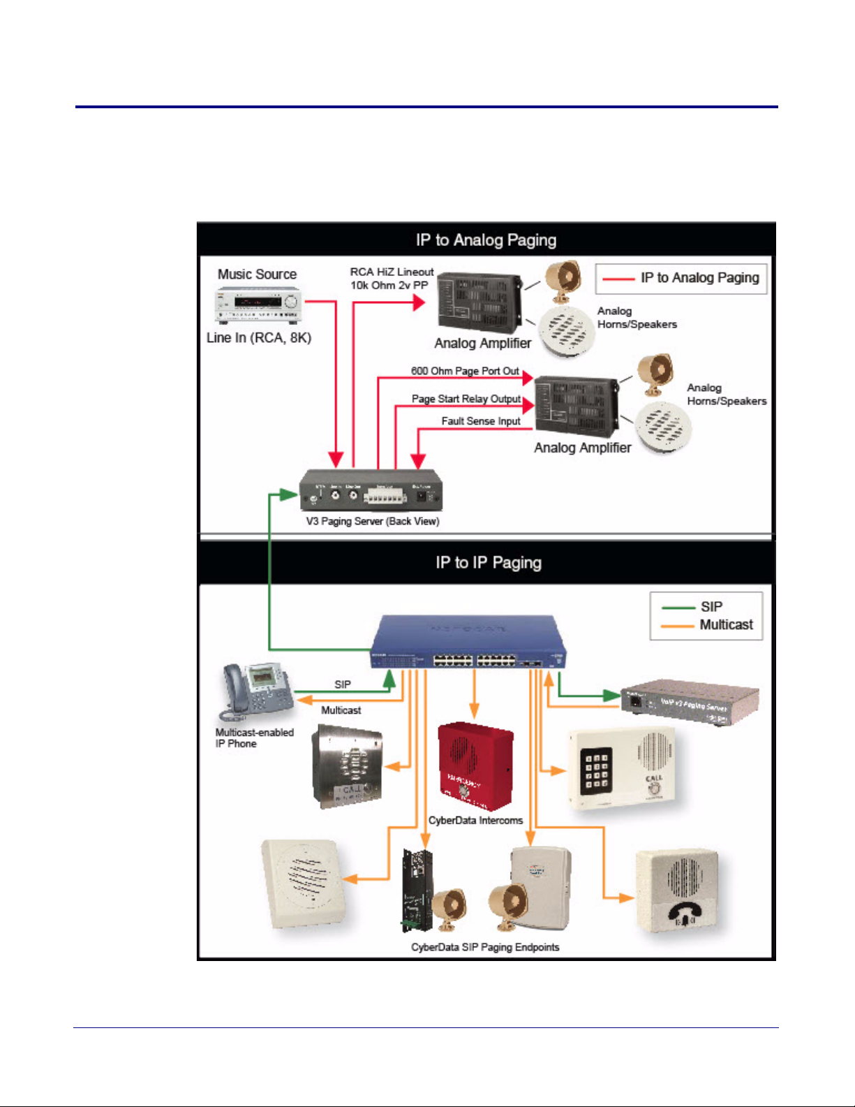
2.2 Typical Installation
Figure 2-2 illustrates how the Paging Server is normally installed as part of a paging system.
Figure 2-2. Typical Installation
Setting Up the Paging Server
6
CyberData Corporation 931073B Operations Guide
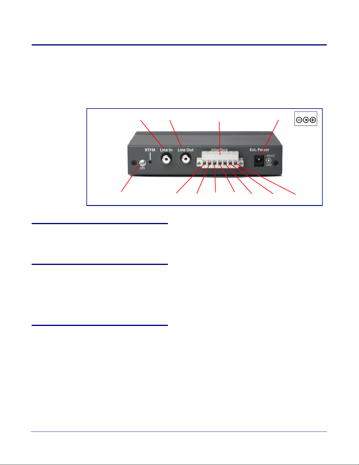
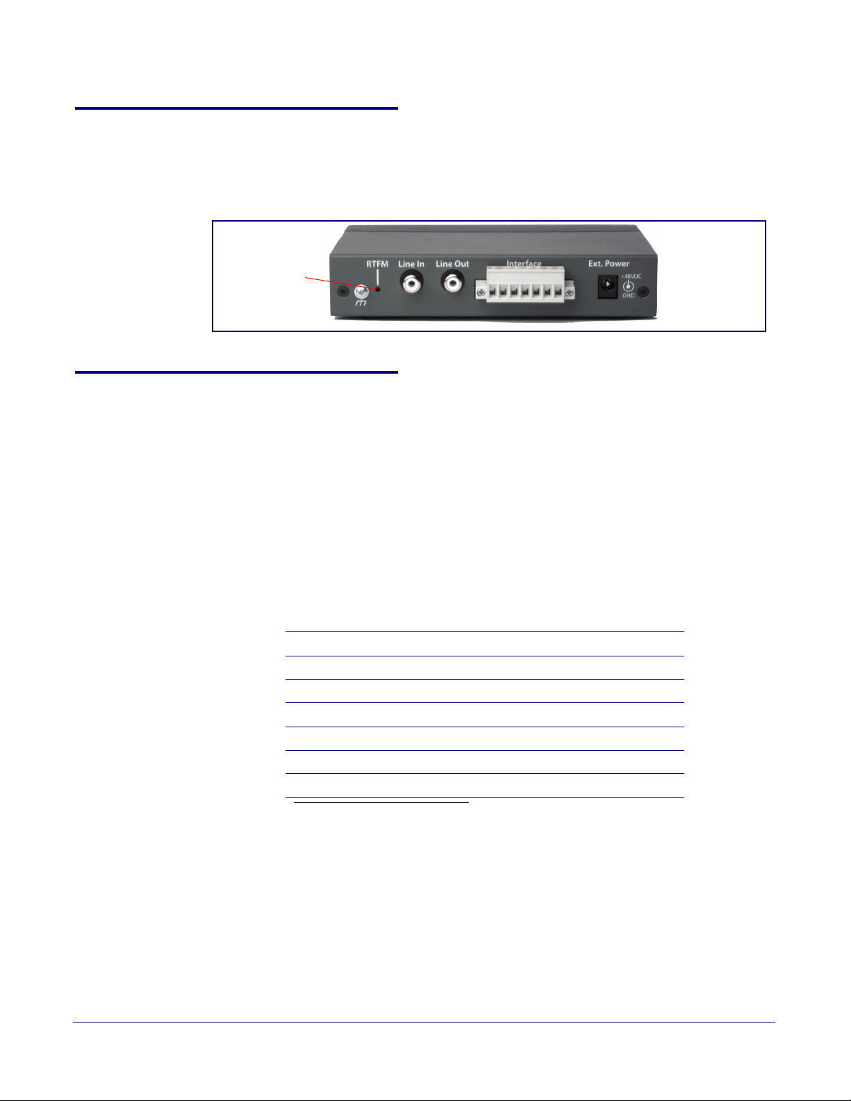
2.3 Connecting the Paging Server
Power
48VDC
Ground Connection
Line In Line Out Page Port Output Connections
Pin 1 Pin 2 Pin 3 Pin 4 Pin 5 Pin 6 Pin 7
Before you connect the Paging Server, be sure that you have received all of the parts described in
Section 2.1, "Parts List".
See Figure 2-3 for the connection options that are available for the Paging Server.
Figure 2-3. Connection Options
Setting Up the Paging Server
Ground Connection
7
2.3.1 Ground Connection
This connection allows you to connect the device to an electrical ground.
2.3.2 Line In
This RCA 10K Ohm Hi-Z input connection allows you to connect the device to The RCA line-out
(10K Ohm Hi-Z) of an external audio amplifier. The level of this input can be controlled by the
potentiometer located on the front of the device (see
Parameters").
2.3.3 Line Out
This RCA 10K Ohm Hi-Z output connection allows you to connect the device to The RCA line-in
(10K Ohm Hi-Z) of an external audio amplifier.
Section 2.4.10, "Configure the Fault Detection
CyberData Corporation 931073B Operations Guide

Setting Up the Paging Server
Page Port Output Connections
2.3.4 Page Port Output Connections
Table 2-1. Page Port Output Connections
Pin Description
Pin 1 Fault Sense Input (Common). See Section 2.3.4.1, "Pin 1 and 2—Fault Sense Input (Common/Sense)".
Pin 2 Fault Sense Input (Sense). See Section 2.3.4.1, "Pin 1 and 2—Fault Sense Input (Common/Sense)".
Pin 3 Positive 600-Ohm Audio Outputa. See Section 2.3.4.2, "Pin 3, 4, and 5—Positive/Negative 600-Ohm Audio
Output/Audio Ground Reference".
a
Pin 4 Negative 600-Ohm Audio Output.
Output/Audio Ground Reference".
Pin 5 Audio Ground Reference. See Section 2.3.4.2, "Pin 3, 4, and 5—Positive/Negative 600-Ohm Audio Output/Audio
Ground Reference".
Pin 6 Relay Contact - Commonb. See Section 2.3.4.3, "Pin 6 and 7—Relay Contact (Common/Normally Open)".
Pin 7 Relay Contact - Normally Open
a. The 600-Ohm audio output of the page port is also suited for interfaces with lower input impedances.
b. 1 Amp at 30 VDC for continuous loads
. See Section 2.3.4.2, "Pin 3, 4, and 5—Positive/Negative 600-Ohm Audio
b
. See Section 2.3.4.3, "Pin 6 and 7—Relay Contact (Common/Normally Open)".
8
2.3.4.1 Pin 1 and 2—Fault Sense Input (Common/Sense)
This input was designed as a method of monitoring an external amplifier that is equipped with a fault
sense relay.
When enabled via the web interface (Section 2.4.10, "Configure the Fault Detection Parameters"),
this input (when closed) will play a user uploadable audio file out of the line-out connection and/or
place a SIP call to a pre-determined extension and play that file.
2.3.4.2 Pin 3, 4, and 5—Positive/Negative 600-Ohm Audio Output/Audio Ground Reference
This output allows direct connection to paging amplifiers requiring a "Page Port" type input that
meets a balanced 600 Ohm 5VPP signal.
2.3.4.3 Pin 6 and 7—Relay Contact (Common/Normally Open)
When enabled on the web interface (Section 2.4.5, "Configure the Device Parameters"), every time
an audio file is played out of the local line-out or 600 Ohm output, the relay will close, thereby
enabling amplifiers with a remote turn-on capability to become active.
CyberData Corporation 931073B Operations Guide
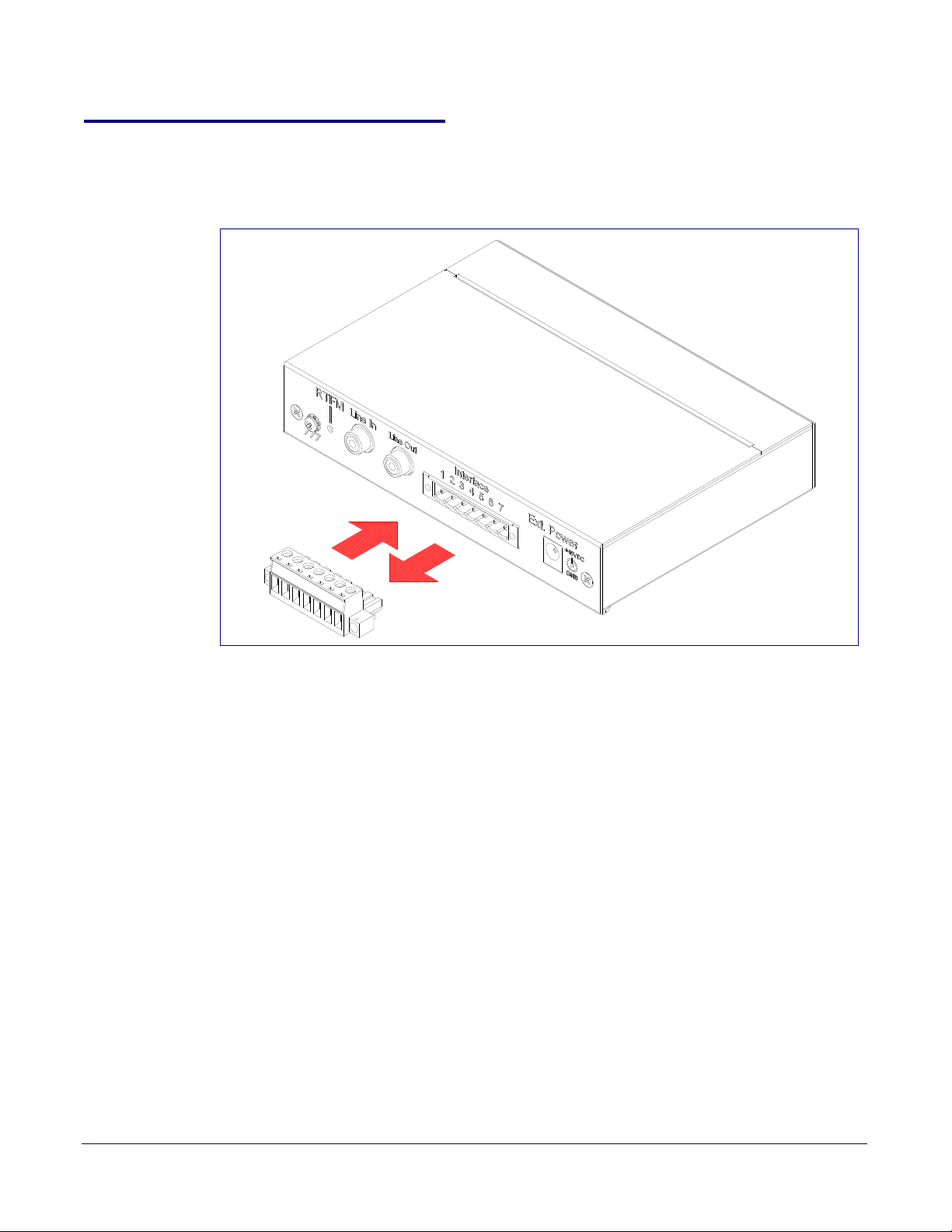
2.3.5 Removable Interface Connector
Figure 2-4 shows the interface connector that is removable on the Paging Server.
Figure 2-4. Removable Interface Connector
Setting Up the Paging Server
Removable Interface Connector
9
CyberData Corporation 931073B Operations Guide

2.3.6 Connect to the Power Source
Non PoE (with 48 VDC power supply)
Chassis Ground
Chassis Ground
PoE
To set up the Paging Server, connect the device
to your network:
Poe
•For PoE, plug one end of an 802.3af
Ethernet cable into the Paging Server
Ethernet port. Plug the other end of the
Ethernet cable into your network. See the
figure on the left.
Non-Poe
•For Non-PoE, connect the Paging Server to
a 48VDC power supply. See the figure on
the left.
• Note: Do not use both PoE and external
power.
• Alternatively, you can use our
part# 010867 PoE Power Injector
as a cost-effective option.
Chassis Ground
• If required, connect the earth grounding wire
to the Chassis Ground. See the figure on
the left.
To use PoE, plug a Cat 5 Ethernet cable from the Paging Server Ethernet port to your network. As
an alternative to PoE, you can plug one end of a +48V DC power supply into the Paging Server, and
plug the other end into a receptacle. If required, connect the earth grounding wire to the chassis
ground on the back of the unit. See
Figure 2-5. Connecting to the Power Source
Figure 2-5.
Setting Up the Paging Server
Connect to the Power Source
10
CyberData Corporation 931073B Operations Guide
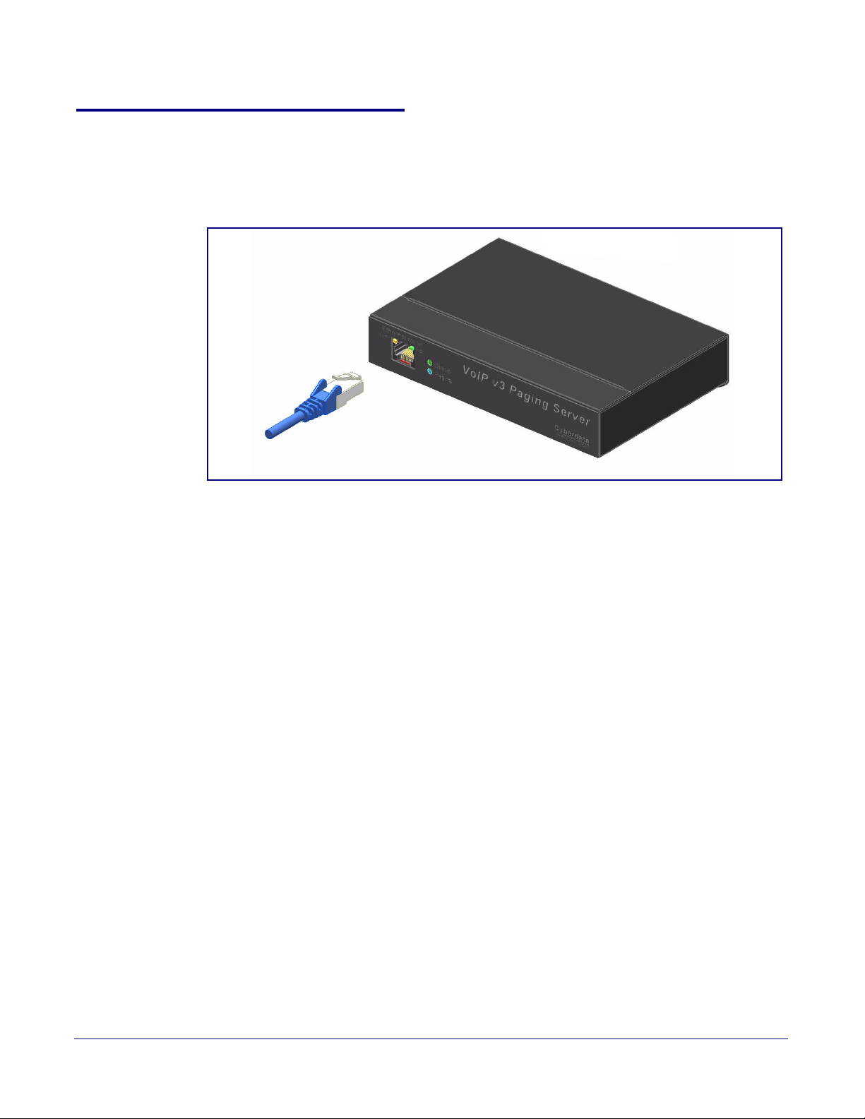
2.3.7 Connect to the Network
Plug one end of a standard Ethernet cable into the Paging Server Ethernet port. Plug the other end
into your network.
Figure 2-6. Connecting to the Network
Setting Up the Paging Server
Connect to the Network
11
CyberData Corporation 931073B Operations Guide
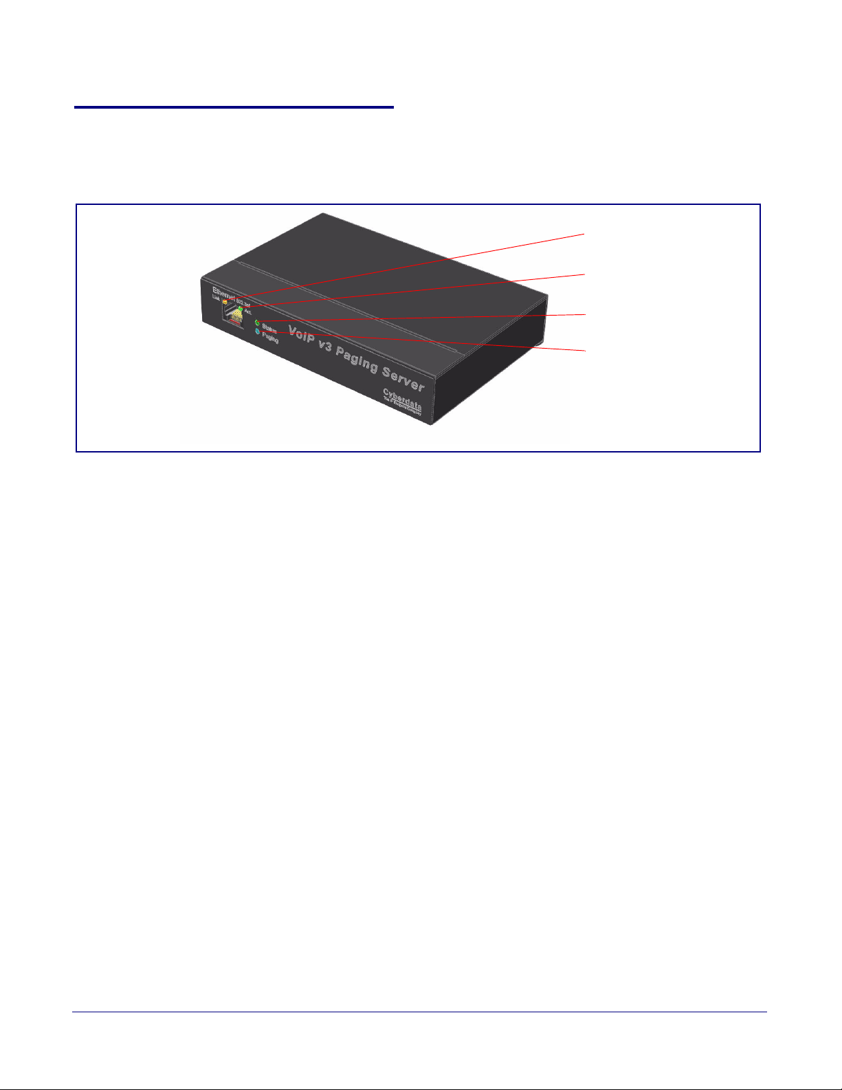
Confirm that the Paging Server is Up and Running
Status
(GREEN/BLUE LED)
Paging
(GREEN LED)
Link
(GREEN/
AMBER LED)
Activity
(GREEN LED)
2.3.8 Confirm that the Paging Server is Up and Running
The LEDs on the front of the Paging Server verify the unit’s operations.
Figure 2-7. Paging Server LEDs
Setting Up the Paging Server
12
2.3.8.1 Confirm Power on, Network Connectivity, and Connection Speed
When you plug in the Ethernet cable or power supply:
•The GREEN/BLUE Status LED and the GREEN Paging LED both blink at a rate of 10 times
per second during the initial network setup.
• The round, GREEN/BLUE Status LED on the front of the Paging Server comes on indicating
that the power is on. Once the device has been initialized, this LED blinks at one second
intervals.
• The square, GREEN/AMBER Link LED above the Ethernet port indicates that the network
connection has been established. The Link LED changes color to confirm the auto-negotiated
connection speed:
• The Link LED is GREEN at 10 Mbps.
• The Link LED is AMBER at 100 Mbps.
• The GREEN Paging LED comes on after the device is booted and initialized. This LED blinks
when a page is in progress. You can disable Beep on Initialization on the Device page.
2.3.8.2 Verify Network Activity
The square, GREEN Activity LED blinks when there is network traffic.
CyberData Corporation 931073B Operations Guide
2.3.9 Announcing the IP Address
RTFM Switch
To announce the IP address for the Paging Server, briefly press and then quickly release the RTFM
switch. See Figure 2-8.
Figure 2-8. RTFM Switch
2.3.10 Restore the Factory Default Settings
The Paging Server is delivered with factory set default values for the parameters in Tab l e 2-3. In
addition, the settings for various UI web pages (such as the Device Page, SIP Page, etc.) are
delivered with the factory default settings and can be restored to these def
the RTFM switch. However, uploaded audio files are not restored to the factory default settings when
you use the RTFM switch.
Setting Up the Paging Server
Announcing the IP Address
ault settings when you use
13
Use the RTFM s
witch (see Figure 2-8) on the back of the unit to restore these parameters to the
factory default settings.
Note Wh
en you perform this procedure, the factory default settings are restored. The default
parameters for access are shown in Ta bl e 2-3.
Table 2-3. Factory Default Settings
Parameter Factory Default Setting
IP Addressing DHCP
IP Address
Web Access Username admin
Web Access Password admin
Subnet Mask
Default Gateway
a
a
a
10.10.10.10
255.0.0.0
10.0.0.1
a. Default if there is not a DHCP server present.
To restore these parameters to the factory default settings:
1. Press and hold the RTFM switch until the status and paging lights come on.
2. Continue to press the RTFM switch until after you see the indicator lights go off and you hear the
ing defaults” announcement.
“restor
CyberData Corporation 931073B Operations Guide
3. Release the RTFM switch.
4. The Paging Server settings are restored to the factory defaults.

Gather the Required Configuration Information
2.4 Configuring the Paging Server
Use this section to configure the VoIP paging server.
2.4.1 Gather the Required Configuration Information
Have the following information available before you configure the Paging Server.
2.4.1.1 Static or DHCP Addressing?
Know whether your system uses static or dynamic (DHCP) IP addressing. If it uses static
addressing, you also need to know the values to assign to the following Paging Server parameters:
• IP Address
• Subnet Mask
• Default Gateway
Setting Up the Paging Server
14
2.4.1.2 Username and Password for Configuration GUI
Determine the Username and Password that will replace the defaults after you initially log in to the
configuration GUI.
• The Username is case-sensitive, and must be from four to 25 alphanumeric characters long.
• The Password is case-sensitive, and must be from four to 20 alphanumeric characters long.
2.4.1.3 SIP Settings
To configure the SIP parameters, determine whether you want to register with the server. If you do,
determine the number of minutes the registration lease remains valid, and whether you want to
automatically unregister when you reboot. To configure the SIP parameters, you also need to
determine the values for these parameters:
• SIP Server IP Address
• Remote and Local SIP Port Numbers
• SIP User ID, and Authenticate ID and Password for this User ID
CyberData Corporation 931073B Operations Guide
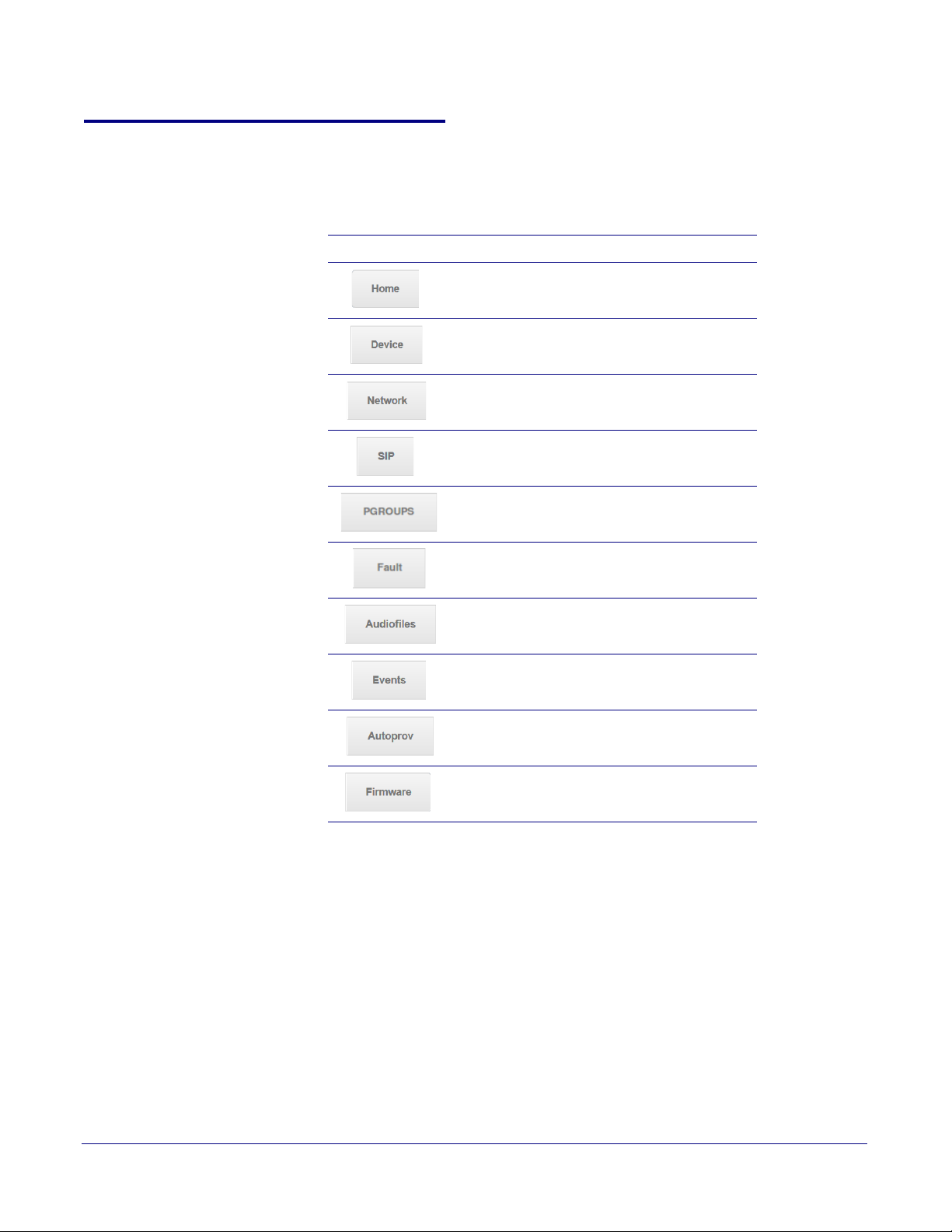
2.4.2 Paging Server Web Page Navigation
Ta bl e 2-4 shows the navigation buttons that you will see on every Paging Server web page.
Table 2-4. Web Page Navigation
Web Page Item Description
Link to the Home page.
Link to the Device page.
Link to the Network page.
Link to go to the SIP page.
Link to the PGROUPS page.
Setting Up the Paging Server
Paging Server Web Page Navigation
15
Link to the Fault page.
Link to the Audiofiles page.
Link to the Events page.
Link to the Autoprovisioning page.
Link to the Firmware page.
CyberData Corporation 931073B Operations Guide
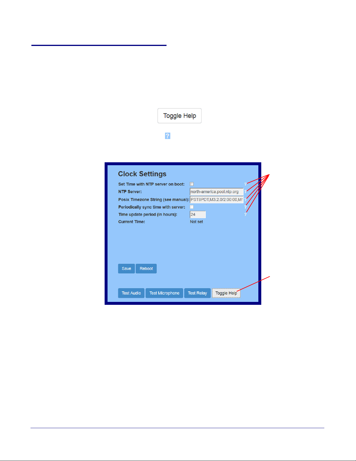
2.4.3 Using the Toggle Help Button
Toggle Help button
Question mark
appears next to the
web page items
The Toggle Help button allows you to see a short description of some of the settings on the
webpage. To use the Toggle Help button, do the following:
Setting Up the Paging Server
Using the Toggle Help Button
16
1. Click on the T
oggle Help button that is on the UI webpage. See Figure 2-9 and Figure 2-10.
Figure 2-9. Toggle/Help Button
2. You will see a question mark ( ) appear next to each web page item that has been provided
with a short description by the Help feature. See Figure 2-10.
Figure 2-10. Toggle Help Button and Question Marks
CyberData Corporation 931073B Operations Guide
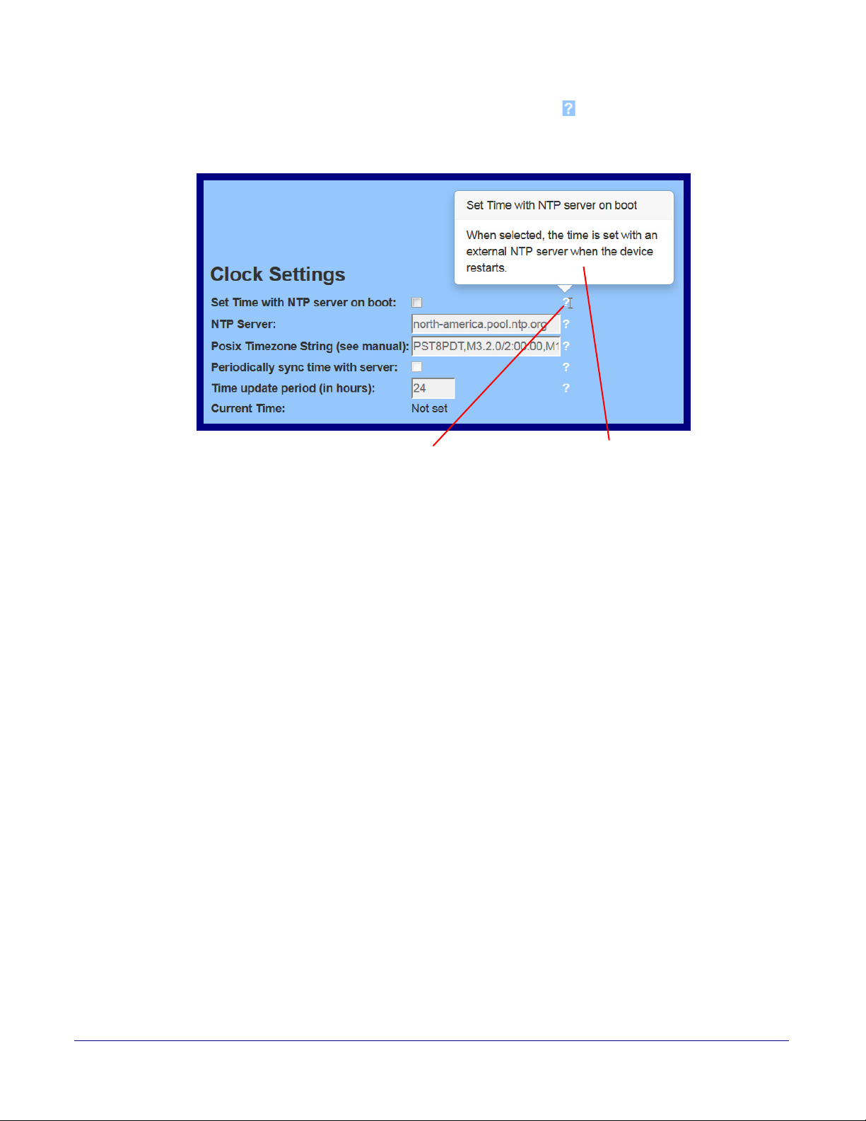
Setting Up the Paging Server
A short description of the
web page item will appear
Question mark
Using the Toggle Help Button
3. Move the mouse pointer to hover over the question mark ( ), and a short description of the web
page item will appear. See Figure 2-11.
Figure 2-11. Short Description Provided by the Help Feature
17
CyberData Corporation 931073B Operations Guide

2.4.4 Log in to the Configuration GUI
1. Open your browser to the Paging Server IP address.
Note If the network does not have access to a DHCP server, the device will default to an IP
address of 10.10.10.10.
Note Make sure that the PC is on the same IP network as the Paging Server.
Note You may also download CyberData’s VoIP Discovery Utility program which allows you to
easily find and configure the default web address of the CyberData VoIP products.
CyberData’s VoIP Discovery Utility program is available at the following website address:
http://www.cyberdata.net/support/voip/discovery_utility.html
The unit ships in DHCP mode. To get to the Home page, use the discovery utility to scan for
the device on the network and open your browser from there.
Note To work with the Paging Server configuration after the initial configuration, log in using the
IP address you assign to the device.
provides instructions for entering the IP address.
Setting Up the Paging Server
Log in to the Configuration GUI
Section 2.4.6, "Configure the Network Parameters"
18
Change the Default Username and Password
2. When prompted, use the following default Username and Password to open the configuration
Home page:
Username: admin
Password: admin
To change the default Web access Username and Password:
1. Enter the new Username from four to 25 alphanumeric characters in the Change Username
field. The Username is case-sensitive.
2. Enter the new Password from four to 20 alphanumeric characters in the Change Password
field. The Password is case-sensitive.
3. Enter the new password again in the Re-enter New Password field.
Click Save Settings.
CyberData Corporation 931073B Operations Guide
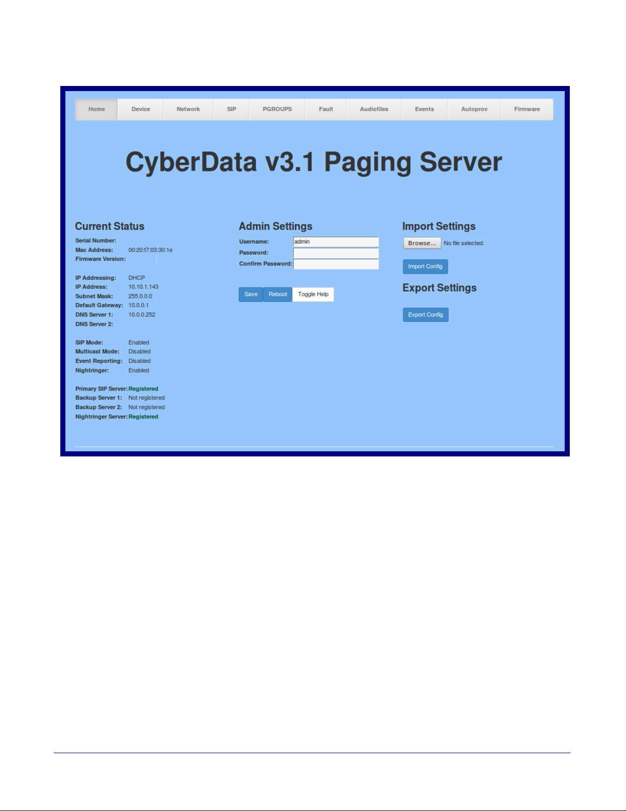
Figure 2-12. Home Page
v11.3.0
146100001
Setting Up the Paging Server
Log in to the Configuration GUI
19
CyberData Corporation 931073B Operations Guide
Setting Up the Paging Server
Log in to the Configuration GUI
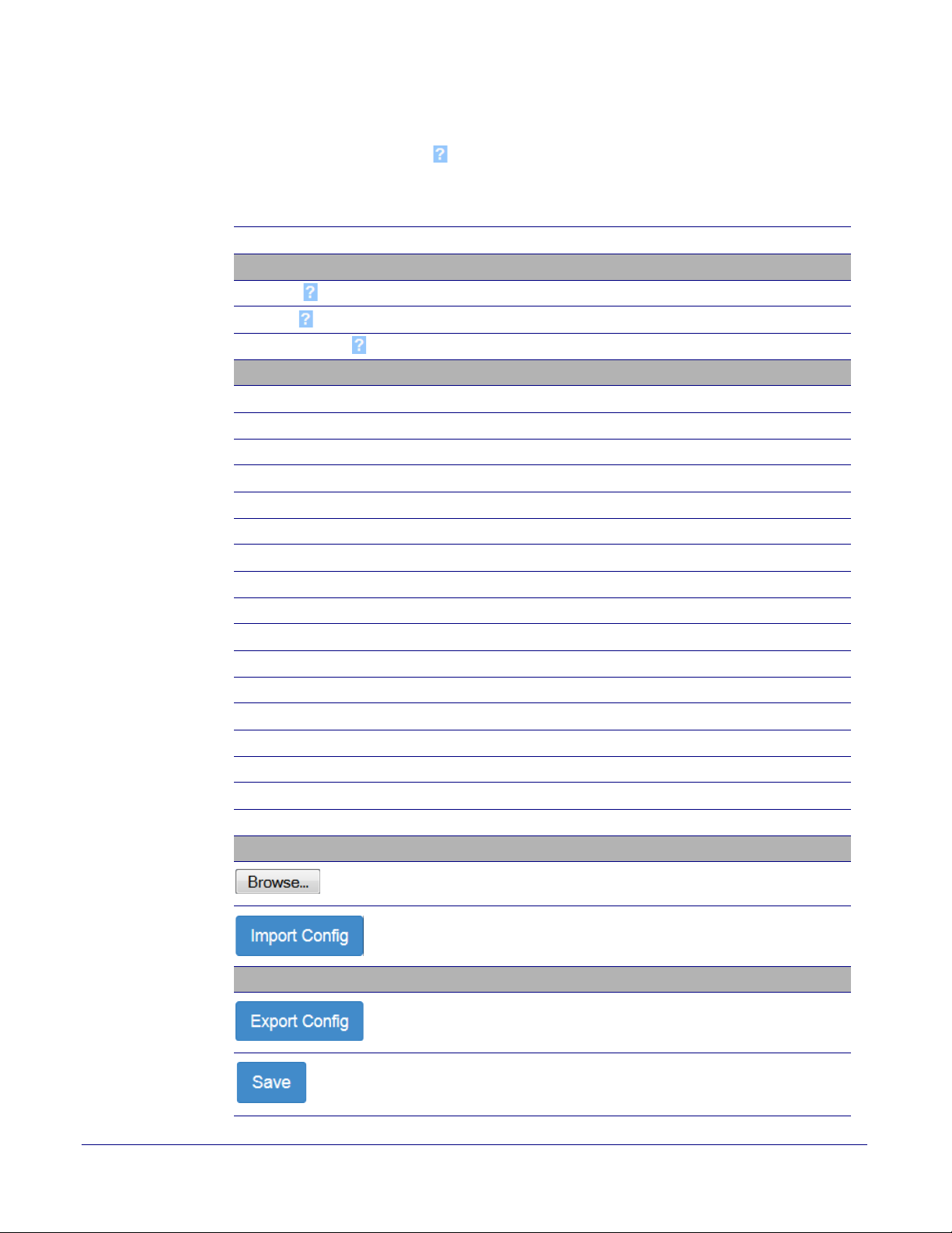
4. On the Home Page, review the setup details and navigation buttons described in Ta b le 2-5
20
Note The question mark icon (
after the T
oggle Help button is pressed.
) in the following table shows which web page items will be defined
Table 2-5. Home Page Overview
Web Page Item
Description
Admin Settings
Username The username to access the web interface. Enter up to 25 characters.
Password The password to access the web interface. Enter up to 25 characters.
Confirm Password
Confirm the web interface password.
Current Status
Serial Number Shows the device serial number.
Mac Address Shows the device Mac address.
Firmware Version Shows the current firmware version.
IP Addressing Shows the current IP addressing setting (D
HCP or static).
IP Address Shows the current IP address.
Subnet Mask Shows the current subnet mask address.
Default Gateway Shows the current default gateway address.
DNS Server 1 Shows the current DNS Server 1 address.
DNS Server 2 Shows the current DNS Server 2 address.
SIP Mode Shows the current status of the SIP mode.
Multicast Mode Shows the current status of the Multicast mode.
Event Reporting Shows the current status of the Event Reporting mode.
Nightringer Shows the current status of the Nightringer mode.
Primary SIP Server Shows the current status of the Primary SIP Server.
Backup Server 1 Shows the current status of Backup Server 1.
Backup Server 2 Shows the current status of Backup Server 2.
Nightringer Server
Shows the current status of Nightringer Server.
Import Settings
Use this button to select a configuration file to import.
After selecting a configuration file, click Import to import the
configuration from the selected file. Then, click Save and Reboot to
store changes.
Export Settings
Click Export to export the current configuration to a file.
Click the Save button to save your configuration settings.
Note: Y
ou need to reboot for changes to take effect.
CyberData Corporation 931073B Operations Guide
 Loading...