

CyberData 011049 Operation Manual

The IP Endpoint Company
SIP Call Button
Operations Guide
Part #011049
Document Part #930801F
for Firmware Version 11.1.0
CyberData Corporation
3 Justin Court
Monterey, CA 93940
(831) 373-2601
SIP Call Button Operations Guide 930801F
Technical Support
The fastest way to get technical support for your VoIP product is to
submit a VoIP Technical Support form at the following website:
http://www.cyberdata.net/support/contactsupportvoip.php
Phone: (831) 373-2601, Ext. 333
Email: support@cyberdata.net
Fax: (831) 373-4193
Company and product information is at www.cyberdata.net.
Part # 011049
COPYRIGHT NOTICE:
© 2015, CyberData Corporation, ALL RIGHTS RESERVED.
This manual and related materials are the copyrighted property of CyberData Corporation. No part of
this manual or related materials may be reproduced or transmitted, in any form or by any means
(except for internal use by licensed customers), without prior express written permission of
CyberData Corporation. This manual, and the products, software, firmware, and/or hardware
described in this manual are the property of CyberData Corporation, provided under the terms of an
agreement between CyberData Corporation and recipient of this manual, and their use is subject to
that agreement and its terms.
DISCLAIMER: Except as expressly and specifically stated in a written agreement executed by
CyberData Corporation, CyberData Corporation makes no representation or warranty, express or
implied, including any warranty or merchantability or fitness for any purpose, with respect to this
manual or the products, software, firmware, and/or hardware described herein, and CyberData
Corporation assumes no liability for damages or claims resulting from any use of this manual or such
products, software, firmware, and/or hardware. CyberData Corporation reserves the right to make
changes, without notice, to this manual and to any such product, software, firmware, and/or
hardware.
OPEN SOURCE STATEMENT: Certain software components included in CyberData products are
subject to the GNU General Public License (GPL) and Lesser GNU General Public License (LGPL)
“open source” or “free software” licenses. Some of this Open Source Software may be owned by third
parties. Open Source Software is not subject to the terms and conditions of the CyberData
COPYRIGHT NOTICE or software licenses. Your right to copy, modify, and distribute any Open
Source Software is determined by the terms of the GPL, LGPL, or third party, according to who
licenses that software.
Software or firmware developed by CyberData that is unrelated to Open Source Software is
copyrighted by CyberData, subject to the terms of CyberData licenses, and may not be copied,
modified, reverse-engineered, or otherwise altered without explicit written permission from
CyberData Corporation.
TRADEMARK NOTICE: CyberData Corporation and the CyberData Corporation logos are
trademarks of CyberData Corporation. Other product names, trademarks, and service marks may be
the trademarks or registered trademarks of their respective owners.
The IP Endpoint Company
CyberData Corporation 930801F Operations Guide

Revision Information
Revision 930801F, which corresponds to firmware version 11.1.0, was released on January 14,
2015, and has the following changes:
• Updates Figure 1-2, "Typical Installation—Door Strike Intermediate Relay Module"
• Updates Figure 1-3, "Typical Installation—Networked Door Strike Intermediate Relay Module"
• Updates Figure 2-13, "Home Page"
• Updates Figure 2-14, "Device Configuration Page"
• Updates Figure 2-16, "Network Configuration Page"
• Updates Figure 2-17, "SIP Configuration Page"
• Updates Figure 2-18, "SIP Configuration Page Set to Point-to-Point Mode"
• Updates Figure 2-19, "Sensor Configuration Page"
• Updates Figure 2-20, "Audio Configuration Page"
• Updates Figure 2-24, "Event Configuration Page"
• Adds Figure 2-25, "DSR Page"
• Adds Figure 2-26, "Relay Status Section"
• Adds Figure 2-27, "DSR Page Configure Device Page"
• Updates Figure 2-28, "Autoprovisioning Page"
• Updates Figure 2-29, "Configuration File"
• Updates Figure 2-30, "Firmware Page"
• Updates Figure 2-31, "Home Page"
• Updates Section 2.2.7, "Call Button and the Call Button LED"
• Updates Section 2.3.13, "Configure the Autoprovisioning Parameters"
• Updates Ta bl e 2-6, "Home Page Overview"
• Updates Ta bl e 2-7, "Device Configuration Parameters"
• Updates Ta bl e 2-12, "Network Configuration Parameters"
• Updates Ta bl e 2-13, "SIP Configuration Parameters"
• Updates Ta bl e 2-16, "Sensor Configuration Parameters"
• Updates Ta bl e 2-17, "Audiofiles Configuration Parameters"
• Updates Ta bl e 2-18, "Events Configuration Parameters"
• Adds Ta bl e 2-19, "DSR Configuration Parameters"
• Adds Ta bl e 2-20, "DSR Page Configure Device Parameters"
• Updates Ta bl e 2-21, "Autoprovisioning Configuration Parameters"
• Adds Ta bl e 2-22, "Autoprovisioning File Name"
• Updates Ta bl e 2-23, "Firmware Parameters"
• Updates Ta bl e 2-24, "Command Interface Post Commands"
Operations Guide 930801F CyberData Corporation

Browsers Supported
The following browsers have been tested against firmware version 11.1.0:
• Internet Explorer (version: 10)
• Firefox (also called Mozilla Firefox) (version: 23.0.1 and 25.0)
• Chrome (version: 29.0.1547.66 m)
• Safari (version: 5.1.7)
Operations Guide 930801F CyberData Corporation
Important Safety Instructions
GENERAL ALERT
GENERAL ALERT
GENERAL ALERT
1. Read these instructions.
2. Keep these instructions.
3. Heed all warnings.
4. Follow all instructions.
5. Do not use this apparatus near water.
6. Clean only with dry cloth.
7. Do not block any ventilation openings. Install in accordance with the manufacturer’s instructions.
8. Do not install near any heat sources such as radiators, heat registers, stoves, or other apparatus
(including amplifiers) that produce heat.
9. Do not defeat the safety purpose of the polarized or grounding-type plug. A polarized plug has
two blades with one wider than the other. A grounding type plug has two blades and a third
grounding prong. The wide blade or the third prong are provided for your safety. If the provided
plug does not fit into your outlet, consult an electrician for replacement of the obsolete outlet.
10. Protect the power cord from being walked on or pinched particularly at plugs, convenience
receptacles, and the point where they exit from the apparatus.
11. Only use attachments/accessories specified by the manufacturer.
12. Refer all servicing to qualified service personnel. Servicing is required when the apparatus has
been damaged in any way, such as power-supply cord or plug is damaged, liquid has been
spilled or objects have fallen into the apparatus, the apparatus has been exposed to rain or
moisture, does not operate normally, or has been dropped.
13. Prior to installation, consult local building and electrical code requirements.
14. WARNING: The SIP Call Button enclosure is not rated for any AC voltages!
Warn in g
Electrical Hazard: This product should be installed by a licensed electrician
according to all local electrical and building codes.
Warn in g
Electrical Hazard: To prevent injury, this apparatus must be securely attached to
the floor/wall in accordance with the installation instructions.
Warn in g
The PoE connector is intended for intra-building connections only and does not
route to the outside plant.
CyberData Corporation 930801F Operations Guide
Pictorial Alert Icons
GENERAL ALERT
Hazard Levels
Danger: Indicates an imminently hazardous situation which, if not avoided, will result in death or
serious injury. This is limited to the most extreme situations.
Warning: Indicates a potentially hazardous situation which, if not avoided, could result in death or
serious injury.
General Alert
This pictorial alert indicates a potentially hazardous situation. This alert will be
followed by a hazard level heading and more specific information about the
hazard.
Ground
This pictorial alert indicates the Earth grounding connection point.
Caution: Indicates a potentially hazardous situation which, if not avoided, could result in minor or
moderate injury. It may also alert users against unsafe practices.
Notice: Indicates a statement of company policy (that is, a safety policy or protection of property).
The safety guidelines for the equipment in this manual do not purport to address all the safety issues
of the equipment. It is the responsibility of the user to establish appropriate safety, ergonomic, and
health practices and determine the applicability of regulatory limitations prior to use. Potential safety
hazards are identified in this manual through the use of words Danger, Warning, and Caution, the
specific hazard type, and pictorial alert icons.
CyberData Corporation 930801F Operations Guide

Abbreviations and Terms
Abbreviation or Term Definition
A-law A standard companding algorithm, used in European digital
communications systems to optimize, i.e., modify, the dynamic range of an
analog signal for digitizing.
AVP Audio Video Profile
Cat 5 TIA/EIA-568-B Category 5
DHCP Dynamic Host Configuration Protocol
LAN Local Area Network
LED Light Emitting Diode
Mbps Megabits per Second.
NTP Network Time Protocol
PBX Private Branch Exchange
PoE Power over Ethernet (as per IEEE 802.3af standard)
RTFM Reset Test Function Management
SIP Session Initiated Protocol
u-law A companding algorithm, primarily used in the digital telecommunication
UC Unified Communications
VoIP Voice over Internet Protocol
CyberData Corporation 930801F Operations Guide

Contents
Chapter 1 Product Overview 1
1.1 How to Identify This Product .....................................................................................................1
1.2 Typical System Installation .......................................................................................................2
1.3 Product Features ......................................................................................................................3
1.4 Supported Protocols .................................................................................................................3
1.5 Supported SIP Servers .............................................................................................................4
1.6 Product Specifications ..............................................................................................................4
Chapter 2 Installing the SIP Call Button 5
2.1 Parts List ..................................................................................................................................5
2.2 SIP Call Button Setup ...............................................................................................................6
1
2.2.1 SIP Call Button Connections ..........................................................................................6
2.2.2 Using the On-Board Relay .............................................................................................7
2.2.3 Wiring the Circuit ............................................................................................................8
2.2.4 Identifying the SIP Call Button Connectors and Jumpers ............................................11
2.2.5 Activity and Link LEDs .................................................................................................13
2.2.6 Restore the Factory Default Settings ...........................................................................14
2.2.7 Call Button and the Call Button LED ............................................................................15
2.3.1 Factory Default Settings ...............................................................................................16
2.3.2 SIP Call Button Web Page Navigation .........................................................................17
2.3.3 Using the Toggle Help Button .......................................................................................18
2.3.4 Log in to the Configuration Home Page .......................................................................20
2.3.5 Configure the Device ....................................................................................................24
2.3.6 Configure the Network Parameters .............................................................................30
2.3.7 Configure the SIP Parameters .....................................................................................33
2.3.8 Configure the Sensor Configuration Parameters ..........................................................40
2.3.9 Configure the Audio Configuration Parameters ............................................................44
2.3.10 Configure the Event Parameters ................................................................................48
2.3.11 Configure the Door Strike Relay .................................................................................53
2.3.12 Configure the Device (on the DSR page) ...................................................................57
2.3.13 Configure the Autoprovisioning Parameters ...............................................................60
2.4.1 Reboot the Device ........................................................................................................74
2.5.1 Command Interface Post Commands ..........................................................................75
Appendix A Mounting the SIP Call Button 1
A.1 Mount the SIP Call Button .......................................................................................................1
Appendix B Troubleshooting/Technical Support 6
B.1 Frequently Asked Questions (FAQ) ..........................................................................................6
B.2 Documentation .........................................................................................................................6
B.3 Contact Information ..................................................................................................................7
B.4 Warranty ...................................................................................................................................8
B.4.1 Warranty & RMA Returns within the United States ........................................................8
B.4.2 Warranty & RMA Returns outside of the United States .................................................9
B.4.3 Spare in the Air Policy ....................................................................................................9
B.4.4 Return and Restocking Policy ........................................................................................9
B.4.5 Warranty and RMA Returns Page ..................................................................................9
Index 10
Operations Guide 930801F CyberData Corporation

1 Product Overview
SIP CALL BUTTON, PoE
011049D / 021104H
049100001
Model number
WWW.CYBERDATA.NET
Serial number begins with 0491
1.1 How to Identify This Product
To identify the SIP Call Button, look for a model number label similar to the one shown in Figure 1-1.
Confirm the following:
● The model number on the label should be 011049.
● The serial number on the label should begin with 0491.
Figure 1-1. Model Number Label
1
Operations Guide 930801F CyberData Corporation

1.2 Typical System Installation
802.3af Compliant Ethernet Switch
IP Phone IP PBX Server
12 34 56
Door Strike
Door Strike Intermediate
Relay Module
SIP Call Button
802.3af Compliant Ethernet Switch
IP Phone IP PBX Server
12 34 56
Door Strike
Networked Door Strike
Intermediate Relay Module
SIP Call Button
The Session Initiation Protocol (SIP) SIP Call Button is a SIP endpoint designed to provide VoIP
phone connectivity in a tamper proof and secure package.
The following figures illustrate how the device can be installed as part of a VoIP phone system.
Figure 1-2. Typical Installation—Door Strike Intermediate Relay Module
Product Overview
Typical System Installation
2
Figure 1-3. Typical Installation—Networked Door Strike Intermediate Relay Module
Operations Guide 930801F CyberData Corporation

1.3 Product Features
● SIP
● User downloadable message up to 80 seconds
● Single button call to pre-set number
● Continuous repeat of message
● Call progress light
● Event-controlled relay
● Tamper sensor
● Web-based setup
● PoE-powered
1.4 Supported Protocols
The SIP Call Button supports:
● SIP
● HTTP Web-based configuration
Provides an intuitive user interface for easy system configuration and verification of SIP Call
Button operations.
● DHCP Client
Dynamically assigns IP addresses in addition to the option to use static addressing.
● RTP
● RTP/AVP - Audio Video Profile
● Audio Encodings
PCMU (G.711 mu-law)
PCMA (G.711 A-law)
Packet Time 20 ms
Product Overview
Product Features
3
Operations Guide 930801F CyberData Corporation

1.5 Supported SIP Servers
Go to the following link to find the SIP Call Button product page which will have information on how to
configure the SIP Call Button for various supported SIP servers:
http://www.cyberdata.net/support/server/index.html
1.6 Product Specifications
Category Specification
Network Rate 10/100 Mbps
Power Requirement PoE 802.3af or 8 to 12 VDC at 1000 mA
Protocol SIP
Part Number 011049
Dimensions 4.5” x 4.5” x 1.5”
Weight
Auxiliary Relay
1.6 lbs./shipping weight of 2.2 lbs.
(0.7 kg/shipping weight of 1.0kg)
1A at 30 VDC
Product Overview
Supported SIP Servers
4
Operations Guide 930801F CyberData Corporation
2 Installing the SIP Call Button
2.1 Parts List
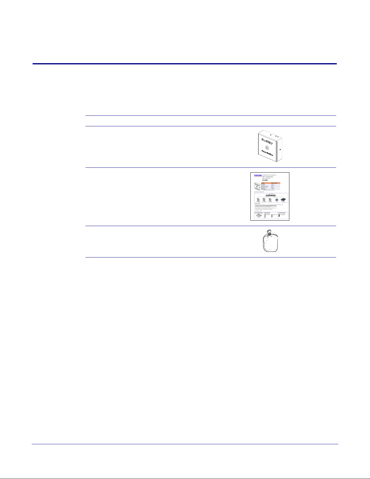
Ta bl e 2-1 illustrates the SIP Call Button parts.
Table 2-1. Parts List
Quantity Part Name Illustration
1 SIP Call Button Assembly
1 Installation Quick Reference Guide
5
1 SIP Call Button Mounting
Accessory Kit
Operations Guide 930801F CyberData Corporation
2.2 SIP Call Button Setup
GENERAL ALERT
J3 Terminal Block
Wire (IN)
can accept 16 AWG wire
*Contacts 1 and 2 on the J3 terminal block are only for
powering the device from a non-PoE 12VDC power
source as an alternative to Network PoE power. Use of
these contacts for any other purpose will damage the
device and void the product warranty.
Relay Contact:
(1 A at 30 VDC for continuous loads)
3 = Relay Common
4 = Relay Normally Open Contact
5 = Sense Input
6 = Sense Ground
2 = Power Ground*
1 = 8 to 12 VDC at 1000 mA*
3
4
Alternate Power Input:
7 = Reserved for Future Use
8 = Reserved for Future Use
1
8
Use a 3.17 mm (1/8-inch) flat blade
screwdriver for the terminal block screws
2.2.1 SIP Call Button Connections
Figure 2-1 shows the pin connections on the J3 (terminal block). This terminal block can accept
16 AWG gauge wire.
Installing the SIP Call Button
SIP Call Button Setup
6
Note As an alternative to using PoE power, you can supply 8 to 12 VDC at 100
terminal block.
Caution
Equipment Hazard: Contacts 1 and 2 on the J3 terminal block are only for
powering the device from a non-PoE 12 VDC power source as an alternative to
Network PoE power. Use of these contacts for any other purpose will damage the
device and void the product warranty.
Figure 2-1. Connections
0 mA into the
Operations Guide 930801F CyberData Corporation

2.2.2 Using the On-Board Relay
GENERAL ALERT
GENERAL ALERT
GENERAL ALERT
Warning
Electrical Hazard:
according to all local electrical and building codes.
Warning
Electrical Hazard:
and momentarily closed configuration. Neither the alternate power input nor PoE
power can be used to drive a door strike.
Warning
Electrical Hazard:
Any use of this relay beyond its normal operating range can cause damage to the
product and is not covered under our warranty policy.
Installing the SIP Call Button
SIP Call Button Setup
This product should be installed by a licensed electrician
The relay contacts are dry and provided for a normally open
The relay does not support AC powered door strikes.
7
The device has a built-in relay that can be activated by a web configurable DTMF string that can be
received from a VoIP phone supporting out of band (RFC2833) DTMF as well as a number of other
triggering events. See the Device Configuration Page on the web interface for relay settings.
This relay can be used to trigger low current devices like strobes and security camera input signals
a
s long as the load is not an inductive type and the relay is limited to a maximum of
1 Amp @ 30 VDC. Inductive loads have caused excessive “hum” and can interfere with the unit’s
e
lectronics.
We highly recommend that inductive load and high current
devices use our Door Strike Intermediate
Relay product (CD# 011269) (see Section 2.2.3.2, "Connecting the Door Strike Intermediate Relay
Module").
This relay interface also has a general purpose input port that can be used to monitor an external
s
witch and generate an event.
For more information on the sensor options, see the Sensor Configuration Page on the web
interface.
Operations Guide 930801F CyberData Corporation
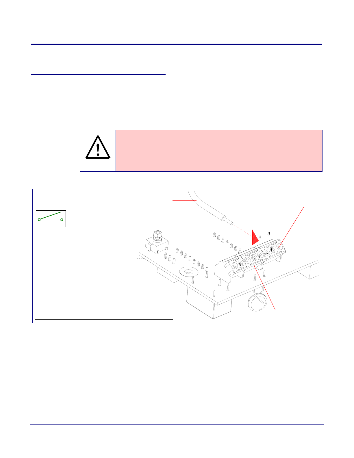
2.2.3 Wiring the Circuit
DC Source
+
1 A @ 30 VDC
Sense Input
Strobe Light
J3 Terminal Block of the CyberData Device
1
8
1
8
The J3 terminal block can accept 16 AWG stranded wire.
Pin 3 - Relay Common
Pin 4 - Relay Normally Open Contact
Pin 5 - Sense Input
Pin 6 - Sense Ground
2.2.3.1 Devices Less than 1A at 30 VDC
If the power for the device is less than 1A at 30 VDC and is not an inductive load, then see
Figure 2-2 for the wiring diagram.
Figure 2-2. Wiring Diagram
Installing the SIP Call Button
SIP Call Button Setup
8
Operations Guide 930801F CyberData Corporation
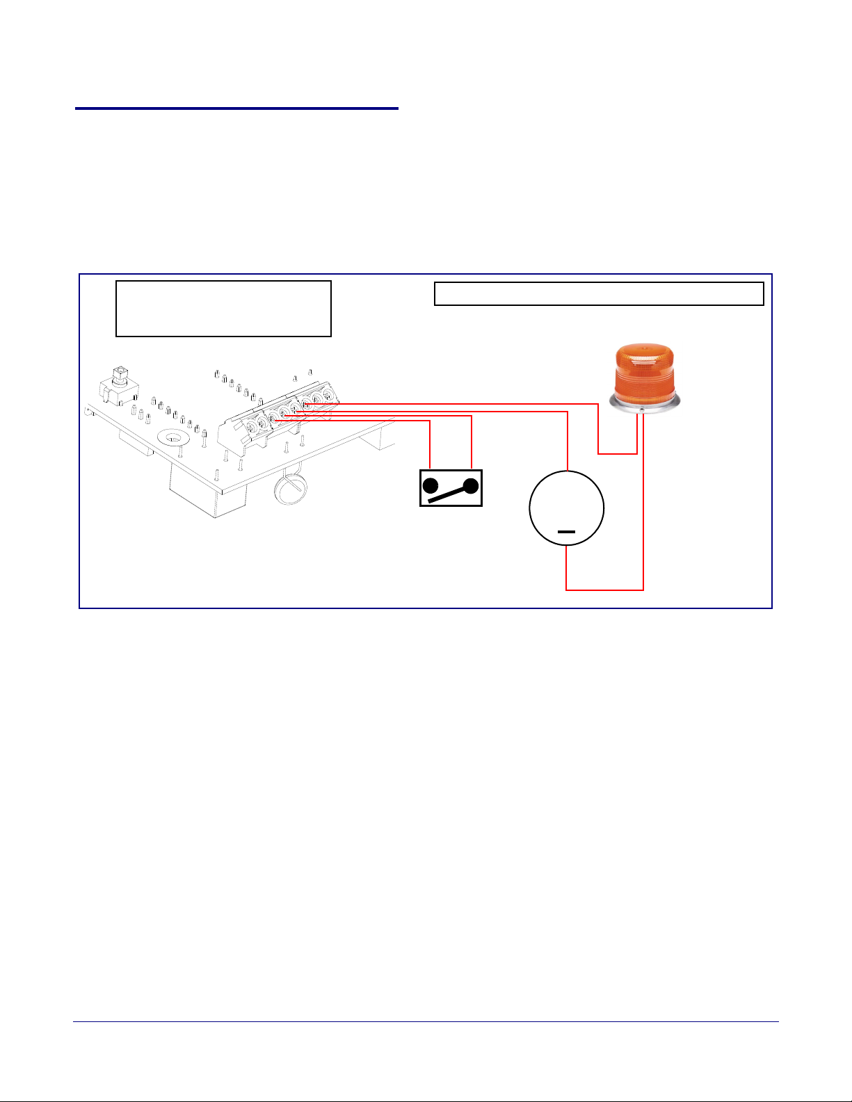
2.2.3.2 Connecting the Door Strike Intermediate Relay Module
Door Lock Sense Input
The J3 terminal block can accept 16 AWG stranded wire.
DC Source
AC Source
OR
+
1
8
J3 Terminal Block
Please refer to the Door Strike Intermediate Relay
Operations Guide for connection specifics.
For wiring an electronic door strike, we recommend the use of our external Door Strike Intermediate
Relay (CD# 011269).
This product provides an easier method of connecting standard door strikes as well as AC and
higher voltage devices. See
Figure 2-3 for the wiring diagram.
Figure 2-3. Wiring Diagram
Installing the SIP Call Button
SIP Call Button Setup
9
If you have questions about connecting door strikes or setting up the web configurable options,
please contact our support department.
http://www.cyberdata.net/support/voip/index.html
Operations Guide 930801F CyberData Corporation
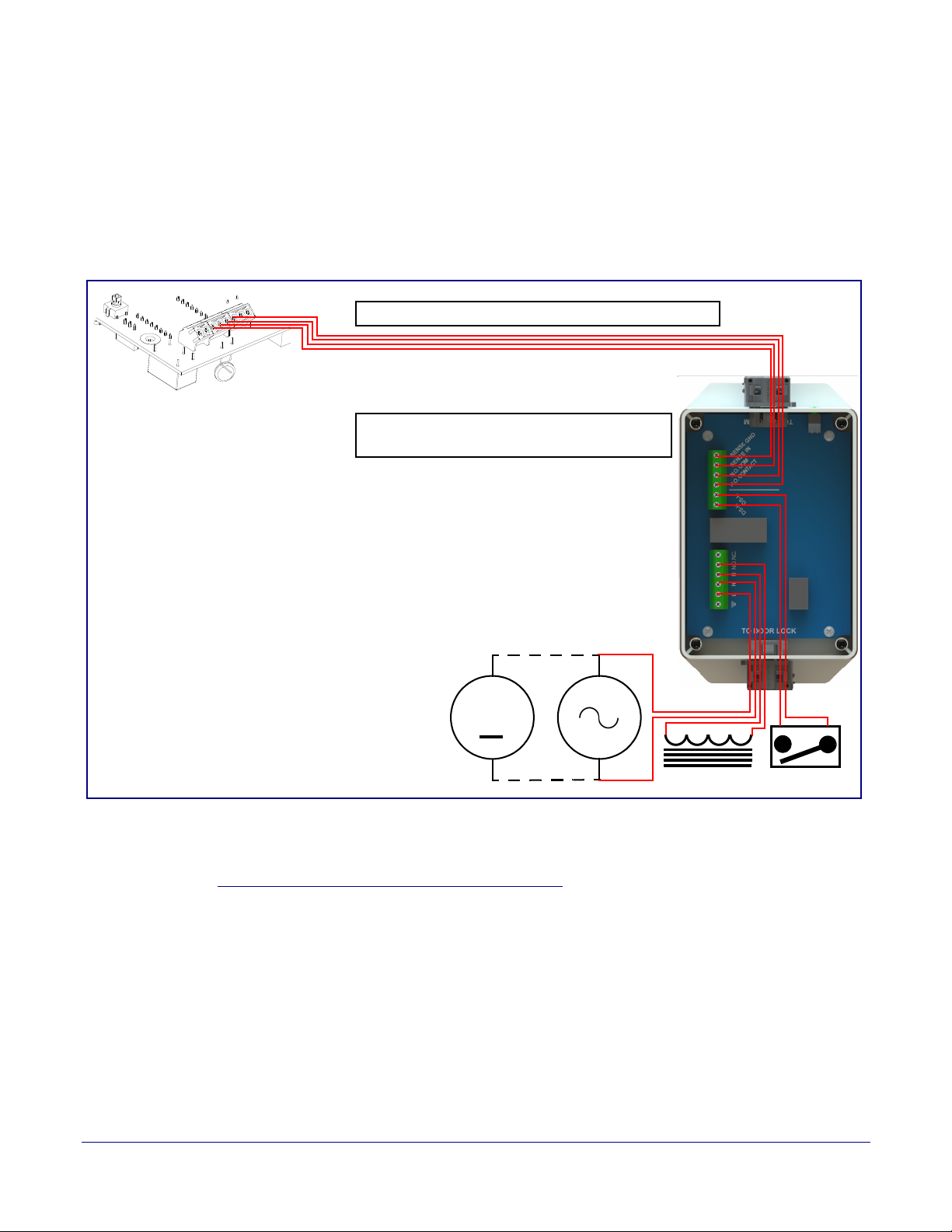
2.2.3.3 Connecting the Networked Door Strike Intermediate Relay
Door Lock
Sense Input
DC Source
AC Source
OR
+
802.3af Compliant Ethernet Switch
CyberData
Aux Button
Device
See Section 2.3.11, "Configure the Door Strike
Relay" for configuration options.
For wiring an electronic door strike to work over a network, we recommend the use of our external
Networked Door Strike Intermediate Relay (CD# 011270).
This product provides an easier method of connecting standard door strikes as well as AC and
higher voltage devices. See
Figure 2-4 for the wiring diagram.
Figure 2-4. Wiring Diagram
Installing the SIP Call Button
SIP Call Button Setup
10
Operations Guide 930801F CyberData Corporation
Installing the SIP Call Button
J9
J7
J6
J10
J2
J8
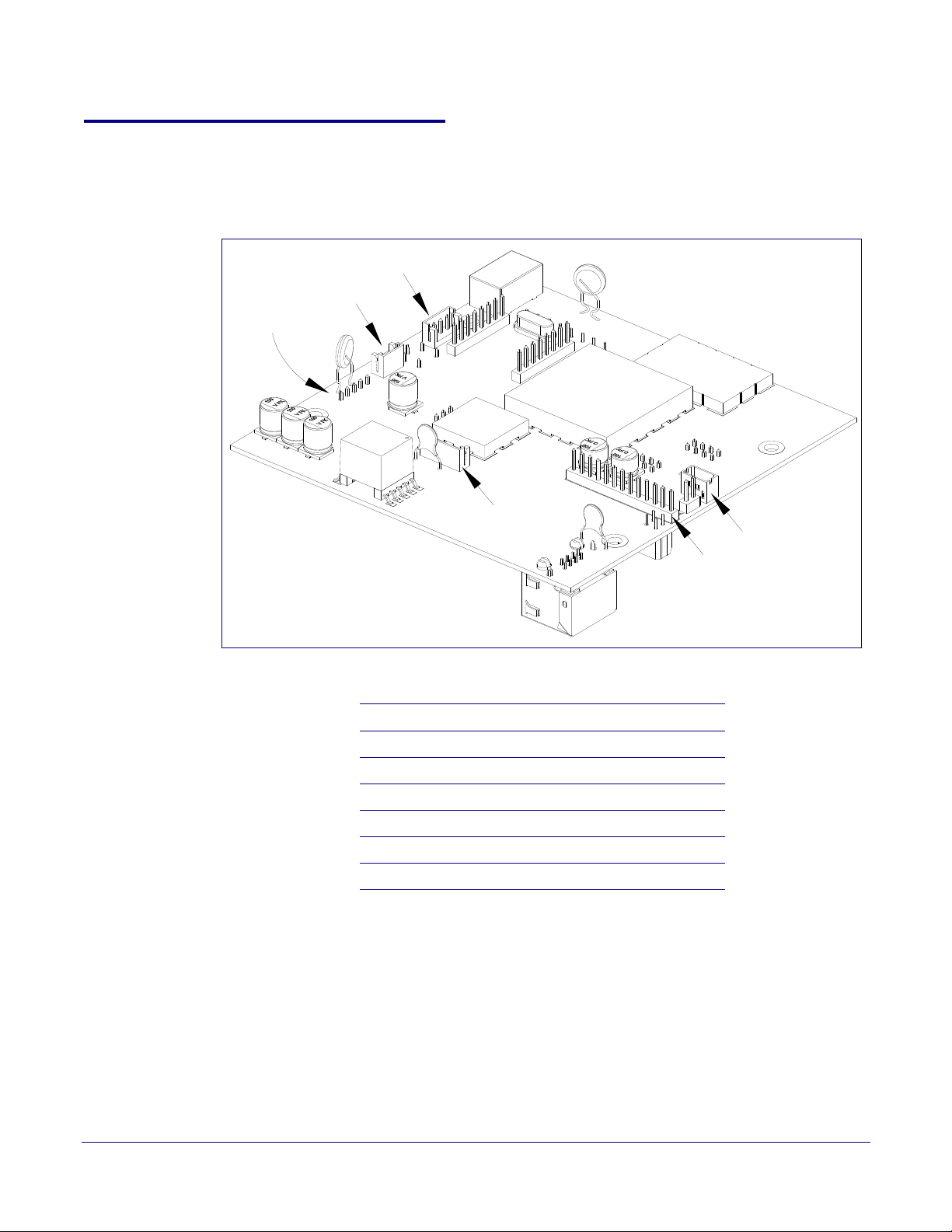
2.2.4 Identifying the SIP Call Button Connectors and Jumpers
See the following figures and tables to identify the SIP Call Button connector locations and functions.
Figure 2-5. Connector Locations
SIP Call Button Setup
11
.
Table 2-2. Connector Functions
Connector Function
J2 Call Button LED Interface — Not Used
J6 Microphone Interface — Not Used
J7 Speaker Interface — Not Used
J8 Keypad Interface — Not Used
J9 Auxiliary Strobe Connector — Not Used
J10 Proximity Sensor Interface — Not Used
Operations Guide 930801F CyberData Corporation
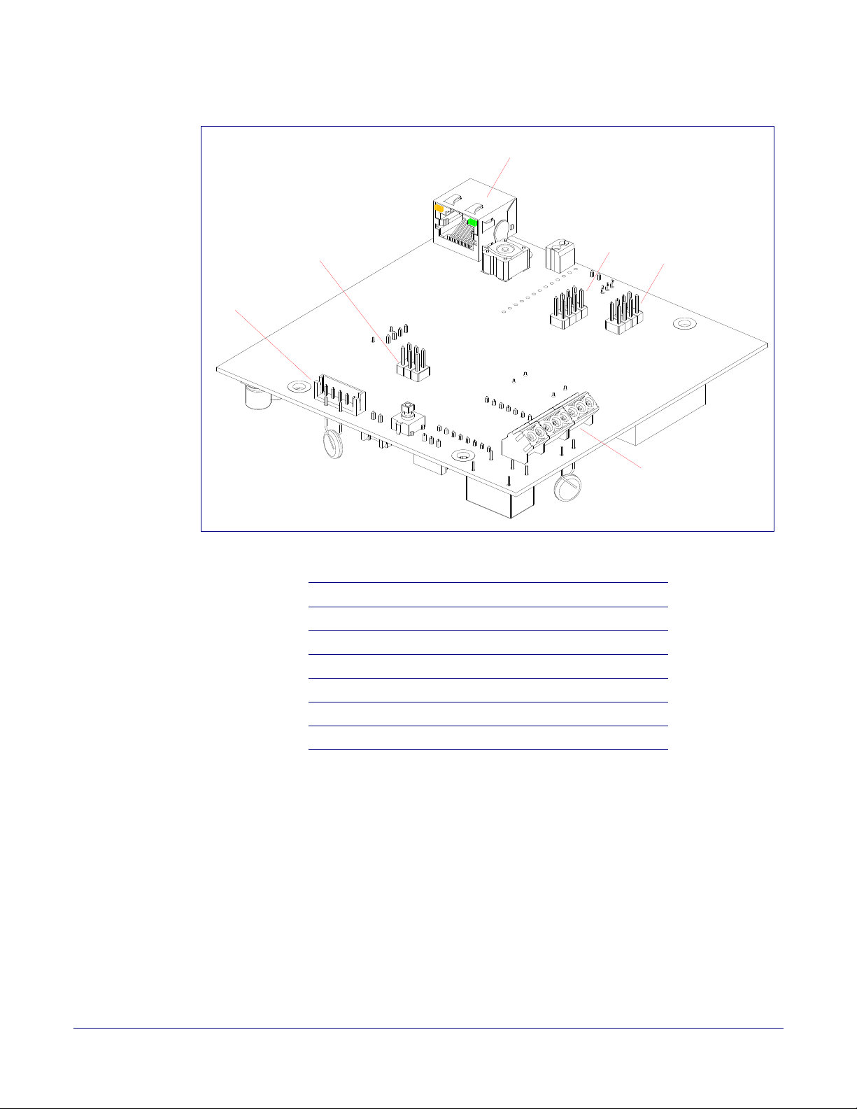
Figure 2-6. Connector Locations
J4
J1
J5
J12
J3
J9
Installing the SIP Call Button
SIP Call Button Setup
12
.
Table 2-3. Connector Functions
Connector Function
J1 PoE Network Connection (RJ-45 ethernet)
J3 Terminal Block (see Figure 2-1)
J4 Console Port (Factory Use Only)
J5 JTAG (Factory Use Only)
J9 Auxiliary Strobe Connector — Not Used
J12 Reserved (Factory Use Only)
Operations Guide 930801F CyberData Corporation
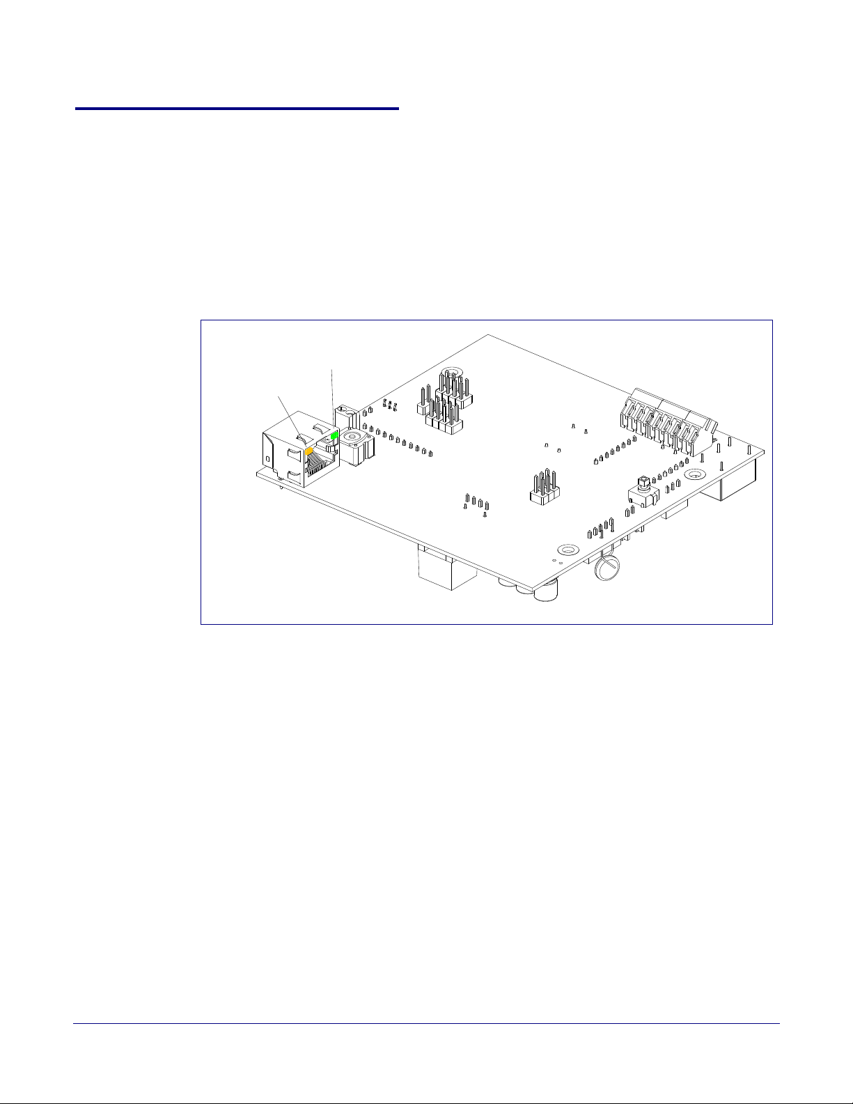
2.2.5 Activity and Link LEDs
Activity
Link
2.2.5.1 Verifying the Network Connectivity and Data Rate
When you plug in the Ethernet cable or power supply to the device, the following occurs:
• The square, YELLOW Activity LED blinks when there is network activity (see Figure 2-7).
• The square, GREEN Link LED above the Ethernet port indicates that the network connection
has been established (see
Figure 2-7).
Figure 2-7. Activity and Link LED
Installing the SIP Call Button
SIP Call Button Setup
13
Operations Guide 930801F CyberData Corporation
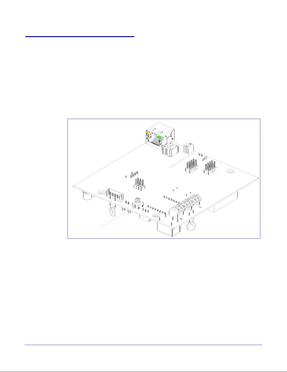
2.2.6 Restore the Factory Default Settings
RTFM
2.2.6.1 RTFM Switch
When the SIP Call Button is operational and linked to the network, use the Reset Test Function
Management (RTFM) switch (
Note Each SIP Call Button is delivered with factory set default values.
Note The SIP Call Button will use DHCP to obtain the new IP address (DHCP-assigned address
or default to 10.10.10.10 if a DHCP server is not present).
Figure 2-8) to set the factory default settings.
Figure 2-8. RTFM Switch
Installing the SIP Call Button
SIP Call Button Setup
14
Operations Guide 930801F CyberData Corporation
To set the factory default settings:
1. Press and hold the RTFM switch until the button LED starts blinking rapidly (about 10 seconds),
then release the RTFM switch.
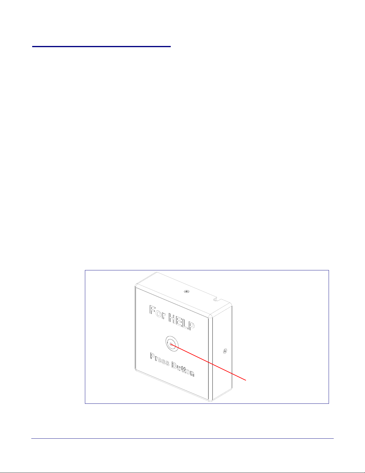
2.2.7 Call Button and the Call Button LED
Call Button and Call Button LED
2.2.7.1 Calling with the The Call Button
• You may initiate a call by pressing the Call Button.
• An active call is indicated by the Call Button LED blinking at one second intervals.
• The Intercom can automatically answer an incoming call.
• You can press the Call Button to terminate an active call.
2.2.7.2 Call Button LED Function
• Upon initial power or reset, the Call Button LED will illuminate.
• On boot, the Call Button LED will flash ten times a second while setting up the network and
downloading autoprovisioning files.
• The device “autoprovisions” by default, and the initial process may take several minutes as the
device searches for and downloads updates. The Call Button LED will blink during this process.
During the initial provisioning, or after the factory defaults have been reset, the device may
download firmware twice. The device will blink, remain solid for 10 to 20 seconds, and then
resume blinking. This process will take longer if there are many audio files downloading.
• When the software has finished initialization, the Call Button LED will blink twice.
• When a call is established (not just ringing), the Call Button LED will blink.
• On the Device Configuration Page (see Section 2.3.5, "Configure the Device"), there is an
option called Button Lit When Idle. This option sets the normal state for the indicator LED. The
Call Button LED will still blink during initialization and calls.
• The Call Button LED flashes briefly at the beginning of RTFM mode.
Installing the SIP Call Button
SIP Call Button Setup
15
Figure 2-9. Call Button and Call Button LED
Operations Guide 930801F CyberData Corporation

2.3 Configure the SIP Call Button Parameters
To configure the SIP Call Button online, use a standard web browser.
Installing the SIP Call Button
SIP Call Button Setup
16
Configure each SIP Call Button and verify its operation bef
mount an SIP Call Button, refer to
2.3.1 Factory Default Settings
All SIP Call Buttons are initially configured with the following default IP settings:
When configuring more than one SIP Call Button, attach the SIP Call Buttons to the network and
conf
igure one at a time to avoid IP address conflicts.
Parameter Factory Default Setting
IP Addressing DHCP
IP Address
Web Access Username admin
Web Access Password admin
Subnet Mask
Default Gateway
a
a
a
a. Default if there is not a DHCP server present.
ore you mount it. When you are ready to
Appendix A, "Mounting the SIP Call Button" for instructions.
Table 2-4. Factory Default Settings
10.10.10.10
255.0.0.0
10.0.0.1
Operations Guide 930801F CyberData Corporation
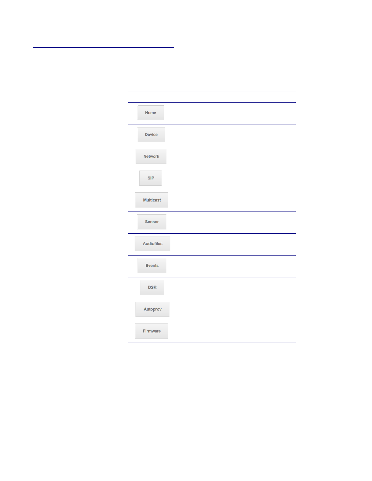
2.3.2 SIP Call Button Web Page Navigation
Ta bl e 2-5 shows the navigation buttons that you will see on every SIP Call Button web page.
Table 2-5. Web Page Navigation
Web Page Item Description
Link to the Home page.
Link to the Device page.
Installing the SIP Call Button
SIP Call Button Setup
17
Link to the Netw
Link to go to the SIP pag
Link to the Multicast page.
Link to the Sensor page.
Link to the Audiofiles page.
Link to the Events page.
Link to the Door Strike Relay page.
Link to the A
Link to the Firmwar
ork page.
e.
utoprovisioning page.
e page.
Operations Guide 930801F CyberData Corporation
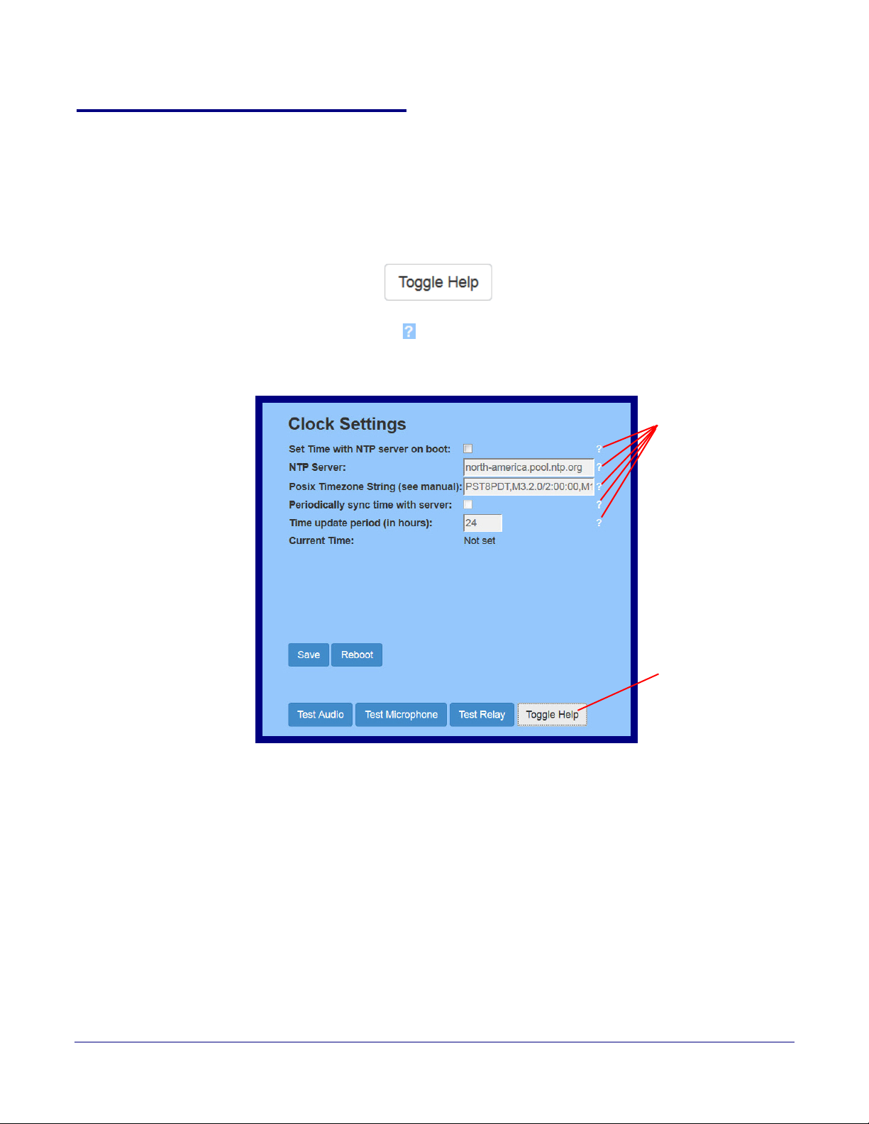
2.3.3 Using the Toggle Help Button
Toggle Help button
Question mark
appears next to the
web page items
The Toggle Help button allows you to see a short description of some of the settings on the
webpage. To use the Toggle Help button, do the following:
Installing the SIP Call Button
SIP Call Button Setup
18
1. Click on the T
oggle Help button that is on the UI webpage. See Figure 2-10 and Figure 2-11.
Figure 2-10. Toggle/Help Button
2. You will see a question mark (
) appear next to each web page item that has been provided
with a short description by the Help feature. See Figure 2-11.
Figure 2-11. Toggle Help Button and Question Marks
Operations Guide 930801F CyberData Corporation
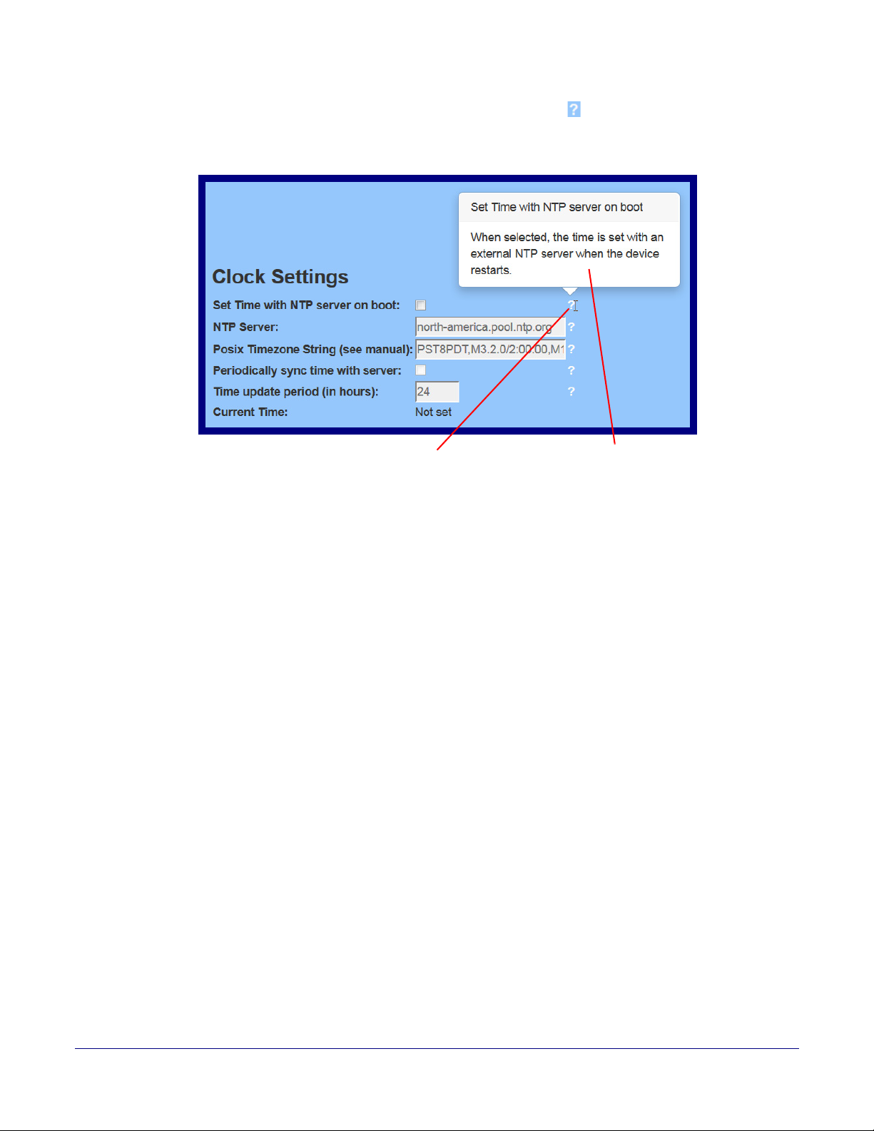
Installing the SIP Call Button
A short description of the
web page item will appear
Question mark
SIP Call Button Setup
3. Move the mouse pointer to hover over the question mark ( ), and a short description of the web
page item will appear. See Figure 2-12.
Figure 2-12. Short Description Provided by the Help Feature
19
Operations Guide 930801F CyberData Corporation

2.3.4 Log in to the Configuration Home Page
1. Open your browser to the SIP Call Button IP address.
Note If the network does not have access to a DHCP server, the device will default to an IP
address of 10.10.10.10.
Note Make sure that the PC is on the same IP network as the SIP Call Button.
Note You may also download CyberData’s VoIP Discovery Utility program which allows you to
easily find and configure the default web address of the CyberData VoIP products.
CyberData’s VoIP Discovery Utility program is available at the following website address:
http://www.cyberdata.net/support/voip/discovery.html
Note The device ships in DHCP mode. To get to the Home page, use the discovery utility to scan
for the device on the network and open your browser from there.
2. When prompted, use the following default Web Access Username and Web Access
Password to access the Home Page (
Web Access Username: admin
Web Access Password: admin
Figure 2-13):
Installing the SIP Call Button
SIP Call Button Setup
20
Operations Guide 930801F CyberData Corporation
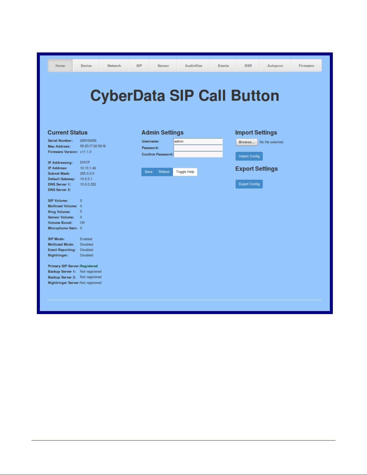
Figure 2-13. Home Page
Installing the SIP Call Button
SIP Call Button Setup
21
Operations Guide 930801F CyberData Corporation
 Loading...