

Page 1
VoIP Zone Controller:
4-Port Audio Out
Operations Guide
SiP Compliant 010881
Document Part #930109C
for Firmware Version 1.0.6
930109C
CyberData Corporation
2555 Garden Road
Monterey, CA 93940
(831) 373-2601
Page 2

Operations Guide 930109C
Phone: (831) 373-2601
Technical Support Ext. 333
[email protected]
Fax: (831) 373-4193
Company and product information at www.CyberData.net
SiP Compliant 010881
COPYRIGHT NOTICE:
© 2010, CyberData Corporation, ALL RIGHTS RESERVED.
This manual and related materials are the copyrighted property of CyberData Corporation. No part
of this manual or related materials may be reproduced or transmitted, in any form or by any means
(except for internal use by licensed customers), without prior express written permission of
CyberData Corporation. This manual, and the products, software, firmware, and/or hardware
described in this manual are the property of CyberData Corporation, provided under the terms of an
agreement between CyberData Corporation and recipient of this manual, and their use is subject to
that agreement and its terms.
DISCLAIMER: Except as expressly and specifically stated in a written agreement executed by
CyberData Corporation, CyberData Corporation makes no representation or warranty, express or
implied, including any warranty or merchantability or fitness for any purpose, with respect to this
manual or the products, software, firmware, and/or hardware described herein, and CyberData
Corporation assumes no liability for damages or claims resulting from any use of this manual or
such products, software, firmware, and/or hardware. CyberData Corporation reserves the right to
make changes, without notice, to this manual and to any such product, software, firmware, and/or
hardware.
OPEN SOURCE STATEMENT: Certain software components included in CyberData products are
subject to the GNU General Public License (GPL) and Lesser GNU General Public License (LGPL)
“open source” or “free software” licenses. Some of this Open Source Software may be owned by
third parties. Open Source Software is not subject to the terms and conditions of the CyberData
COPYRIGHT NOTICE or software licenses. Your right to copy, modify, and distribute any Open
Source Software is determined by the terms of the GPL, LGPL, or third party, according to who
licenses that software.
Software or firmware developed by Cyberdata that is unrelated to Open Source Software is
copyrighted by CyberData, subject to the terms of CyberData licenses, and may not be copied,
modified, reverse-engineered, or otherwise altered without explicit written permission from
CyberData Corporation.
TRADEMARK NOTICE: CyberData Corporation and the CyberData Corporation logos are
trademarks of CyberData Corporation. Other product names, trademarks, and service marks may be
the trademarks or registered trademarks of their respective owners.
CyberData Corporation 930109C Operations Guide
Page 3

Revision History
Revision Date
Released
A 5/29/2007 This is the first release of this manual
B 12/19/2008 Adds information about the Beep Before Page, Bypass DTMF, and RTFM
C 9/7/2010 Updates Section 2.3.4, “Restore the Factory Default Settings as Required”.
Description of Changes
Announce features in Table 2-5, "Zones Setup Parameters".
Adds redundant page button definitions in every web page table.
Firmware: This revision provides information for firmware version 1.0.6.
Release notes detailing the difference between this firmware version and
earlier firmware versions is available in the firmware zip file at the following
URL:
http://www.cyberdata.net/support/voip/index.html
Updates Section B.1, “Frequently Asked Questions (FAQ)”.
Updates Section B.1.1, “Documentation”.
Updates Section B.2, “Contact Information”.
Updates Section B.3, “Warranty”.
CyberData Corporation 930109C Operations Guide
Page 4

4
Chapter
CyberData Corporation 930109C Operations Guide
Page 5

Contents
Chapter 1 Product Overview 1
Chapter 2 Implementing the VoIP Zone Controller 3
2.1 Parts List ..................................................................................................................................................3
2.2 Typical Installation .................................................................................................................................4
2.3 Setting up the VoIP Zone Controller ...................................................................................................5
2.4 Configuring the VoIP Zone Controller ...............................................................................................8
2.5 Set up the Zones ...................................................................................................................................18
2.6 Operating the VoIP Zone Controller .................................................................................................20
2.7 Upgrading the Firmware ...................................................................................................................20
2.8 Rebooting the VoIP Zone Controller ................................................................................................22
i
2.3.1 Connect to the Power Source ...................................................................................................5
2.3.2 Connect to the Network ............................................................................................................5
2.3.3 Confirm that the VoIP Zone Controller is Up and Running ................................................6
Confirm Power on, Network Connectivity, and Baud Rate ..................................................6
Verify Network Activity .............................................................................................................6
2.3.4 Restore the Factory Default Settings as Required .................................................................7
2.4.1 Gather the Required Configuration Information ..................................................................8
Static or DHCP Addressing? ......................................................................................................8
Username and Password for Configuration GUI ...................................................................8
SIP Settings ...................................................................................................................................8
2.4.2 Log in to the Configuration GUI ..............................................................................................8
2.4.3 Configure the Network Parameters ......................................................................................10
2.4.4 Change the Default Username and Password ..................................................................... 13
2.4.5 Configure the SiP Parameters .................................................................................................14
Appendix A Setting Up a TFTP Server 23
A.1 Set up a TFTP Server ..........................................................................................................................23
A.1.1 In a Linux Environment ..........................................................................................................23
A.1.2 In a Windows Environment ...................................................................................................23
Appendix B Troubleshooting/Technical Support 25
B.1 Frequently Asked Questions (FAQ) ..................................................................................................25
B.1.1 Documentation ..........................................................................................................................25
B.2 Contact Information ............................................................................................................................ 25
B.3 Warranty ............................................................................................................................................... 26
B.3.1 Warranty & RMA Returns within the United States ...........................................................26
B.3.2 Warranty & RMA Returns Outside of the United States ....................................................26
B.3.3 Spare in the Air Policy .............................................................................................................27
B.3.4 Return and Restocking Policy .................................................................................................27
B.3.5 Warranty and RMA Returns Page ..........................................................................................27
Index 29
VoIP Zone Controller 4-Port Audio Out Operations Guide 930109C CyberData Corporation
Page 6

ii
CyberData Corporation 930109C VoIP Zone Controller 4-Port Audio Out Operations Guide
Page 7
1 Product Overview
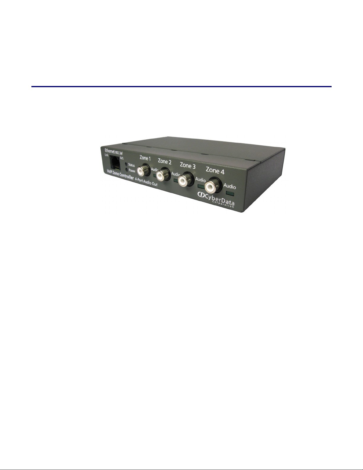
The VoIP Zone Controller is a PoE-enabled, single SIP-endpoint enabling user defined paging zones
through a line-out connection to legacy analog amplifiers connected to existing legacy analog
paging speakers.
SIP compliant IP-PBX's can now interface with existing legacy analog paging speaker installations.
1
Product features
● SIP compliancy
● 10/100BaseT Ethernet Connection
● Page any combination of zones in 15 configurable groups
● TFTP-based firmware upgrades
● PoE enabled
● Connector for optional external power supply
VoIP Zone Controller 4-Port Audio Out Operations Guide 930109C CyberData Corporation
Page 8

2
Product Overview
Supported
Product specifications
● HTTP Web-based configuration
● Provides an intuitive GUI for easy system configuration and verification of speaker operations.
● DHCP Client
● TFTP Client
● Audio Codec
● G.711 U-law
● DTMF detection
VoIP Zone Controller Specifications
Regulatory Compliance FCC Class A, UL 60950, CE
Power Requirement PoE or 48V DC
Baud Rate 10/100 Mbps
Protocol SiP compliant
Part Number 010881
Dimensions 6.11”L x 4.05”W x 1.15” H
Weight 1.2 pounds
CyberData Corporation 930109C VoIP Zone Controller 4-Port Audio Out Operations Guide
Page 9
2 Implementing the VoIP Zone Controller
The topics in this chapter provide information on setting up, configuring, and using the VoIP Zone
Controller.
2.1 Parts List
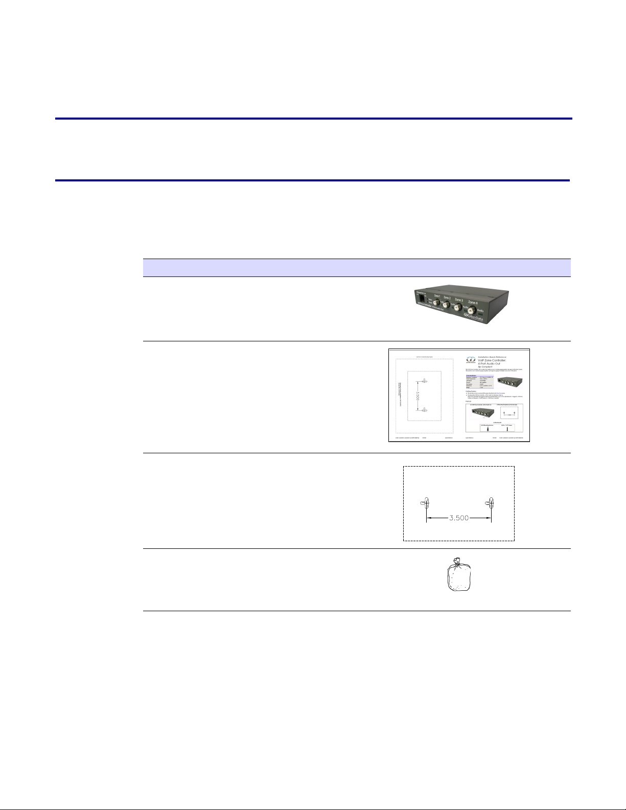
The packaging for the VoIP Zone Controller includes the parts in this illustration.
Table 2-1. Parts List
Quantity Par t Nam e Illustration
1 VoIP Zone Controller
3
1 Installation Quick Reference Guide
1 Mounting Template (located on the last
page of the Installation Quick
Reference)
1 Mounting Kit (part #070057A)
which includes:
(2) #4-6 x 7/8" Mounting Anchors
(2) #4 x 1-1/4" Round Phillips Wood
Screws
VoIP Zone Controller 4-Port Audio Out Operations Guide 930109C CyberData Corporation
Page 10
4
Implementing the VoIP Zone Controller
Typical Installation
2.2 Typical Installation
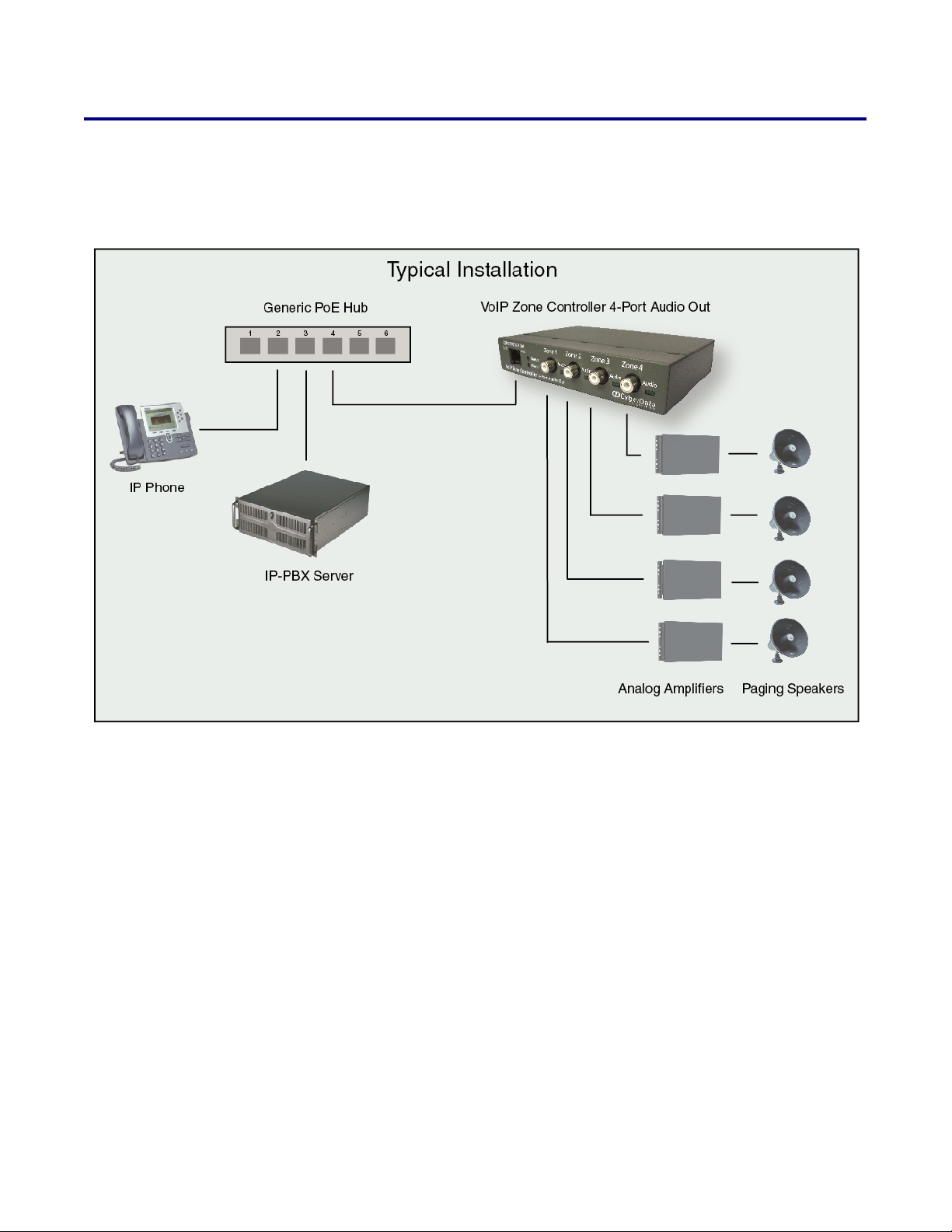
Figure 2-1 illustrates how the VoIP Zone Controller is normally installed as part of a paging system.
Figure 2-1. Typical Installation
CyberData Corporation 930109C VoIP Zone Controller 4-Port Audio Out Operations Guide
Page 11
2.3 Setting up the VoIP Zone Controller
Chassis
ground
Before you set up the VoIP Zone Controller, be sure that you have received all the parts described in
Section 2.1, "Parts List".
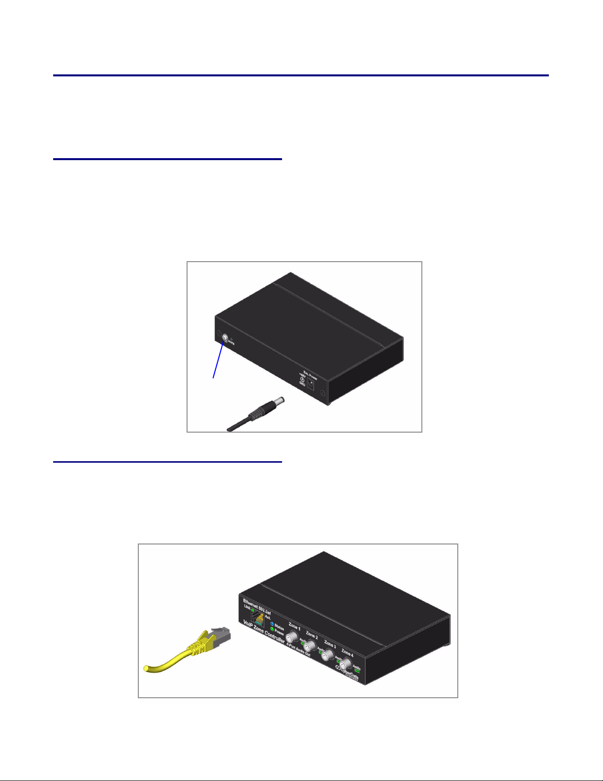
2.3.1 Connect to the Power Source
To use PoE, plug a Cat 5 Ethernet cable from the VoIP Zone Controller Ethernet port to your
network. As an alternative to PoE, you can plug one end of a +48V DC power supply into the VoIP
Zone Controller, and plug the other end into a receptacle. If required, connect the earth grounding
wire to the chassis ground on the back of the unit.
Figure 2-2. Connecting to the Power Source
Implementing the VoIP Zone Controller
Setting up the VoIP Zone Controller
5
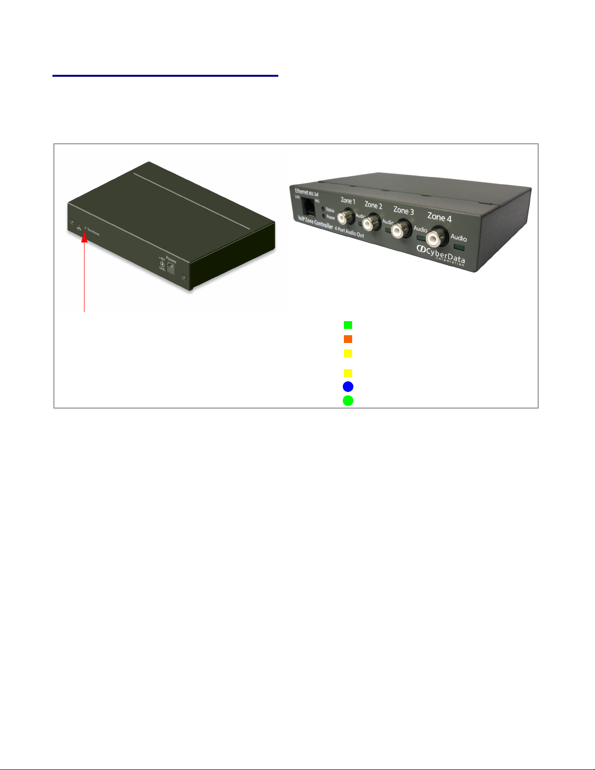
2.3.2 Connect to the Network
Plug one end of a standard Ethernet cable into the VoIP Zone Controller Ethernet port. Plug the
other end into your network.
Figure 2-3. Connecting to the Network
VoIP Zone Controller 4-Port Audio Out Operations Guide 930109C CyberData Corporation
Page 12
6
RTFM switch
On when network connection is established
Link
Orange when baud rate = 100Mbps
Yellow when baud rate = 10Mbps
Blinks to indicate network activityAct.
Status
Paging
Blinks when unit is up and running
Blinks when unit is paging
Implementing the VoIP Zone Controller
Setting up the VoIP Zone Controller
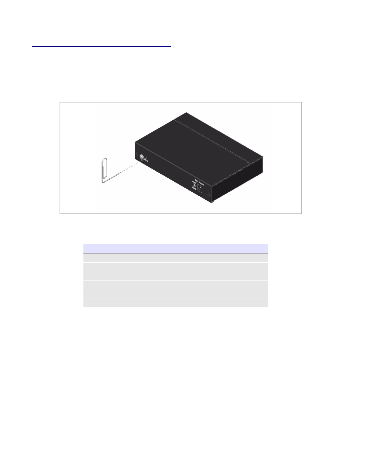
2.3.3 Confirm that the VoIP Zone Controller is Up and Running
The indicator lights on the front of the VoIP Zone Controller verify the unit’s operations.
Figure 2-4. VoIP Zone Controller Indicator Lights
2.3.3.1 Confirm Power on, Network Connectivity, and Baud Rate
2.3.3.2 Verify Network Activity
CyberData Corporation 930109C VoIP Zone Controller 4-Port Audio Out Operations Guide
When you plug in the Ethernet cable or power supply:
● The round, blue Status light on the front of the VoIP Zone Controller comes on indicating that
the power is on. Once the device has been initialized, this light blinks at one second intervals.
● The square, green Link light above the Ethernet port indicates that the network connection has
been established. The Link light changes color to confirm the auto-negotiated baud rate:
• This light is yellow at 10 Mbps.
• It is orange at 100 Mbps.
● The green Paging light comes on after the device is booted and initialized. This light blinks
when a page is in progress.
The square, yellow Act light blinks when there is network activity.
Page 13
Implementing the VoIP Zone Controller
2.3.4 Restore the Factory Default Settings as Required
The VoIP Zone Controller is delivered with factory set default values for the following parameters.
Use the RTF M switch (see
factory default settings.
Figure 2-5) on the back of the unit to restore these parameters to the
Figure 2-5. RTFM Switch
7
Setting up the VoIP Zone Controller
Note When you perform this procedure, the factory default settings are restored for all the
following parameters.
Paramet er Factory Default Setting
IP Addressing static
IP Address 192.168.3.10
Subnet Mask 255.255.255.0
Default Gateway 192.168.3.1
Username admin
Password admin
To restore these parameters to the factory default settings:
1. Press and hold the RTFM switch until the paging lights come on.
2. Continue to hold the RTFM switch after the lights go off.
3. Continue to hold the RTFM switch until the audio lights come on a second time (approximately
10 to 12 seconds).
4. Release the RTFM switch.
5. Wait for approximately five seconds.
6. Power down the device.
7. Wait for approximately 10 seconds.
8. Power on the device. The unit should now be restored to factory defaults.
VoIP Zone Controller 4-Port Audio Out Operations Guide 930109C CyberData Corporation
Page 14

8
Implementing the VoIP Zone Controller
Configuring the VoIP Zone Controller
2.4 Configuring the VoIP Zone Controller
Use this section to configure the VoIP Zone Controller.
2.4.1 Gather the Required Configuration Information
Have the following information available before you configure the VoIP Zone Controller.
2.4.1.1 Static or DHCP Addressing?
Know whether your system uses static or dynamic (DHCP) IP addressing. If it uses static
addressing, you also need to know the values to assign to the following VoIP Zone Controller
parameters:
● IP Address
● Subnet Mask
● Default Gateway
2.4.1.2 Username and Password for Configuration GUI
Determine the Username and Password that will replace the defaults after you initially log in to the
configuration GUI.
● The Username is case-sensitive, and must be from four to 25 alphanumeric characters long.
● The Password is case-sensitive, and must be from four to 20 alphanumeric characters long.
2.4.1.3 SIP Settings
To configure the SIP parameters, determine whether you want to register the VoIP Zone Controller.
If you do, determine the number of minutes the registration lease remains valid, and whether you
want to automatically unregister when you reboot. To configure the SIP parameters, you also need
to determine the values for these parameters:
● SIP Server IP Address
● Remote and Local SIP Port Numbers
● SIP User ID, and Authenticate ID and Password for this User ID
2.4.2 Log in to the Configuration GUI
To log in:
1. For the initial configuration of the VoIP Zone Controller, open your browser and enter the
following address:
http://192.168.3.10
CyberData Corporation 930109C VoIP Zone Controller 4-Port Audio Out Operations Guide
Page 15
Implementing the VoIP Zone Controller
Configuring the VoIP Zone Controller
Note To work with the VoIP Zone Controller configuration after the initial configuration, log in
using the IP address you assign to the device.
Section 2.4.3, "Configure the Network
Parameters" provides instructions for entering the IP address.
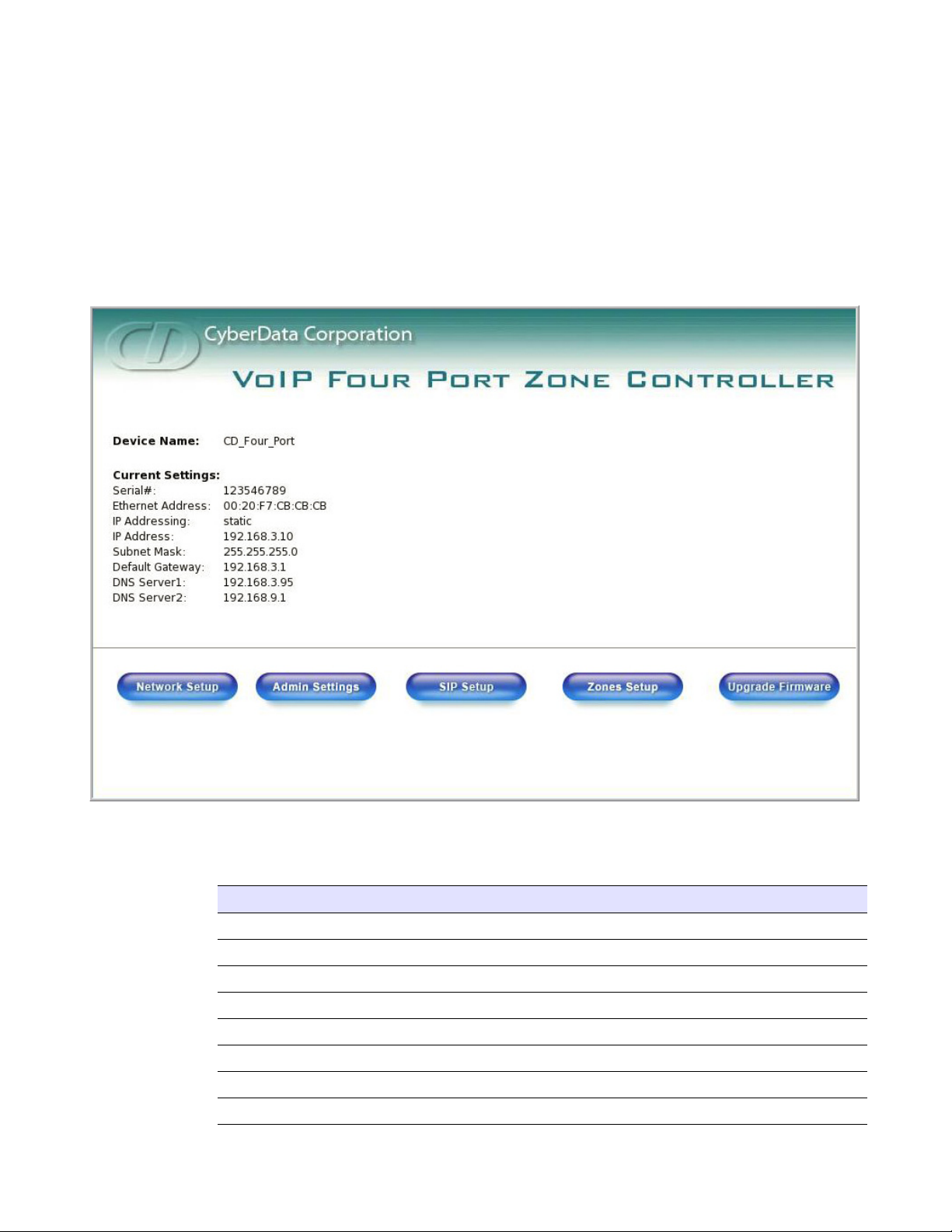
2. When prompted, use the following default Username and Password to open the configuration
Home page:
Username: admin
Password: admin
Figure 2-6. Home Page
9
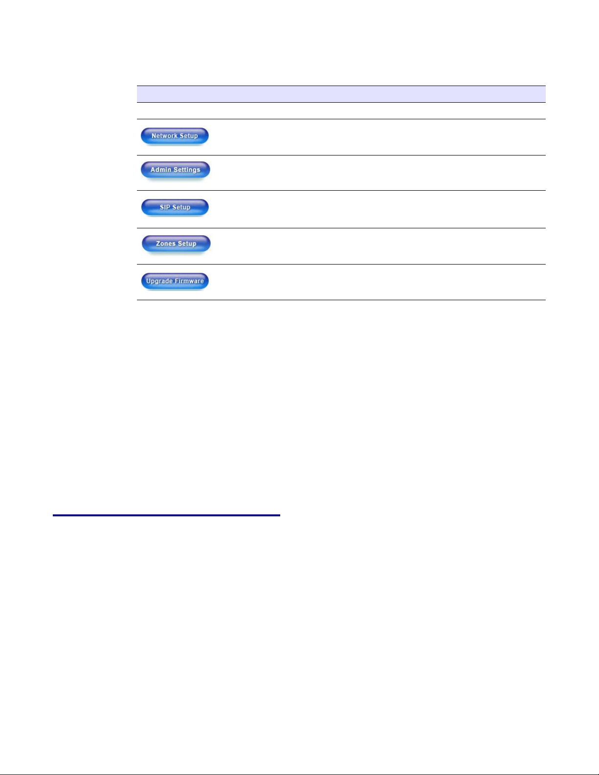
3. On the Home Page, review the setup details and navigation buttons described in Tab le 2-1.
Table 2-1. Home Page Overview
Web Page Item Description
Device Name Shows the device name.
Serial # Device serial number.
Ethernet Address Device ethernet address.
IP Addressing Shows the current IP addressing setting (DHCP or static).
IP Address Shows the current IP address.
Subnet Mask Shows the current subnet mask address.
Default Gateway Shows the current default gateway address.
DNS Server 1 Shows the DNS Server 1 address.
VoIP Zone Controller 4-Port Audio Out Operations Guide 930109C CyberData Corporation
Page 16
10
Implementing the VoIP Zone Controller
Configuring the VoIP Zone Controller
Web Page Item Description
DNS Server 2 Shows the DNS Server 2 address.
At this point you can:
● Review the VoIP Zone Controller’s Current Settings. Use the RTFM switch to restore the factory
default settings. See
● Configure the network parameters. Click Network Setup and refer to Section 2.4.3, "Configure
the Network Parameters" for instructions.
● Configure the Admin parameters. Click Admin Settings and refer to Section 2.4.4, "Change the
Default Username and Password" for instructions.
● Configure the SIP parameters. Click SIP Setup and see Section 2.4.5, "Configure the SiP
Parameters".
● Configure the Zones parameters. Click Zones Setup and refer to ....for instructions.
Table 2-1. Home Page Overview (continued)
Link to the Network Setup web page.
Link to the Admin Settings web page.
Link to the SIP Setup web page.
Link to the Zones Setup web page.
Link to the Upgrade Firmware web page.
Section 2.3.4, "Restore the Factory Default Settings as Required".
Note Click the Upgrade Firmware button any time you need to upload new versions of the
firmware or Reboot the VoIP Zone Controller. Refer to
Section 2.7, "Upgrading the
Firmware" and Section 2.8, "Rebooting the VoIP Zone Controller" for instructions.
2.4.3 Configure the Network Parameters
Configuring the network parameters enables your network to recognize the VoIP Zone Controller
and communicate with it. Click Network Setup on the Home page to open the Network
Configuration page.
CyberData Corporation 930109C VoIP Zone Controller 4-Port Audio Out Operations Guide
Page 17
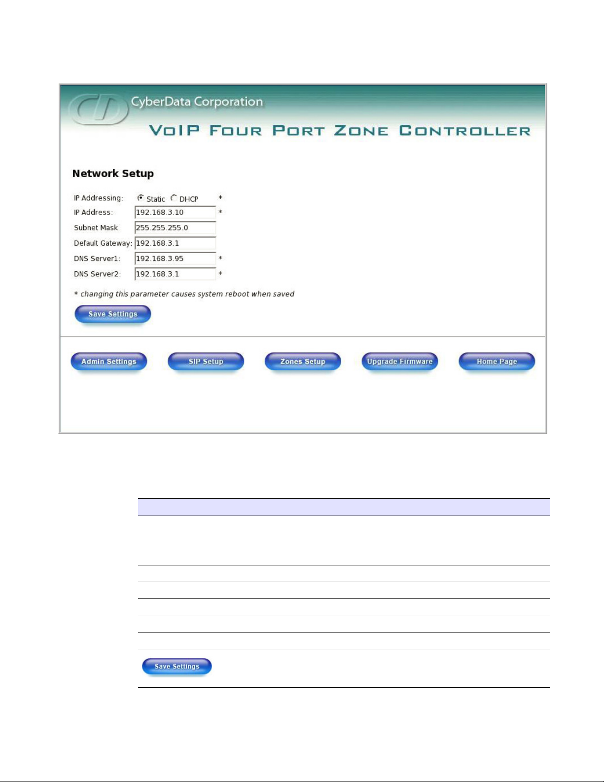
Figure 2-7. Network Setup Page
Implementing the VoIP Zone Controller
Configuring the VoIP Zone Controller
11
On the Network Setup page, enter values for the parameters indicated in Ta ble 2-2.
Table 2-2. Network Setup Parameters
Web Page Item Description
IP Addressing* Select either DHCP IP Addressing or Static IP Addressing by
marking the appropriate radio button. If you select Static, configure
the remaining parameters indicated in
Table 2-2. If you select DHCP,
go to Step 3.
IP Address* Enter the Static IP address.
Subnet Mask Enter the Subnet Mask address.
Default Gateway Enter the Default Gateway address.
DNS Server 1* Enter the DNS Server 1 address.
DNS Server 2* Enter the DNS Server 2 address.
Click on this button to save your configuration settings. Changing a
parameter that has an asterisk next to it will cause a system reboot
when saved.
VoIP Zone Controller 4-Port Audio Out Operations Guide 930109C CyberData Corporation
Page 18
12
Implementing the VoIP Zone Controller
Configuring the VoIP Zone Controller
Web Page Item Description
On this page:
1. Specify whether you use Static or DHCP IP Addressing by marking the appropriate radio
button. Then, if you select Static, go to
Table 2-2. Network Setup Parameters (continued)
Link to the Admin Settings web page.
Link to the SIP Setup web page.
Link to the Zones Setup web page.
Link to the Upgrade Firmware web page.
Link to the Home page.
Step 2.
Note Changing the IP Addressing selection causes the system to reboot when click Save Settings.
2. For Static IP Addressing, also enter values for the following parameters:
a. The VoIP Zone Controller’s IP Address: The VoIP Zone Controller is delivered with a
factory default IP address. Change the default address to the correct IP address for your
system.
Note Changing the VoIP Zone Controller’s IP Address causes the system to reboot when you
click Save Settings.
b. The Subnet Mask.
c. The Default Gateway.
3. Click Save Settings when you finish.
CyberData Corporation 930109C VoIP Zone Controller 4-Port Audio Out Operations Guide
Page 19
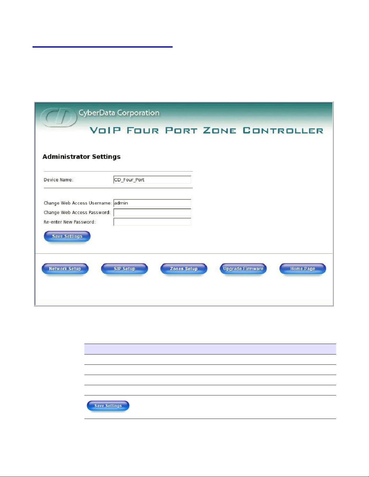
2.4.4 Change the Default Username and Password
On the Home page, click Admin Settings to open the Administrate Settings page. After changing
the Username and Password on this page, new browser requests will require you to log in using
these new parameters.
Figure 2-8. Administrator Settings Page
Implementing the VoIP Zone Controller
Configuring the VoIP Zone Controller
13
4. On the Administrator Settings page, enter values for the parameters indicated in Tab l e 2-3.
Table 2-3. Administrator Settings Parameters
Web Page Item Description
Device Name Enter the name of the device.
Change Web Access Username Use this field to change the Web Access Username
Change Web Access Password Use this field to change the Web Access Password
Re-enter New Password Use this field to re-enter a new password
Click on this button to save your configuration settings.
Changing a parameter that has an asterisk next to it will
cause a system reboot when saved.
VoIP Zone Controller 4-Port Audio Out Operations Guide 930109C CyberData Corporation
Page 20
14
Implementing the VoIP Zone Controller
Configuring the VoIP Zone Controller
Web Page Item Description
To change the default Web access Username and Password:
1. Enter the new Username from four to 25 alphanumeric characters in the Change Username
field. The Username is case-sensitive.
Table 2-3. Administrator Settings Parameters (continued)
Link to the Network Setup web page.
Link to the SIP Setup web page.
Link to the Zones Setup web page.
Link to the Upgrade Firmware web page.
Link to the Home page.
2. Enter the new Password from four to 20 alphanumeric characters in the Change Password field.
The Password is case-sensitive.
3. Enter the new password again in the Re-enter New Password field.
4. Click Save Settings.
2.4.5 Configure the SiP Parameters
The SIP parameters enable the VoIP Zone Controller to contact and register with the SIP server. On
the Home page, click SIP Setup to open the SIP Configuration page.
CyberData Corporation 930109C VoIP Zone Controller 4-Port Audio Out Operations Guide
Page 21
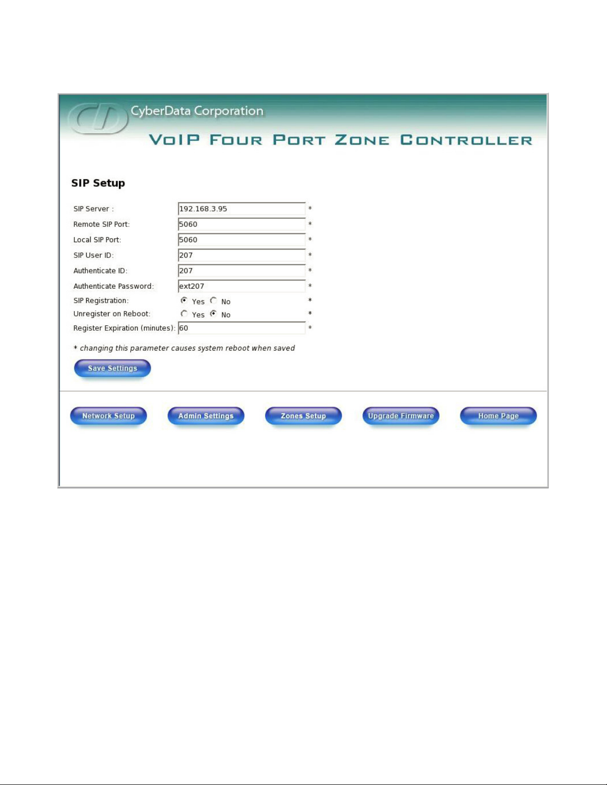
Figure 2-9. SIP Setup Page
Implementing the VoIP Zone Controller
Configuring the VoIP Zone Controller
15
VoIP Zone Controller 4-Port Audio Out Operations Guide 930109C CyberData Corporation
Page 22
16
Implementing the VoIP Zone Controller
Configuring the VoIP Zone Controller
1. On the SIP Setup page, enter values for the parameters indicated in Ta bl e 2-4.
Web Page Item Description
SIP Server* Enter the SIP server represented as either a numeric IP
Remote SIP Port* Enter the Remote SIP Port number (default is 5060).
Local SIP Port* Enter the Local SIP Port number (default is 5060).
SIP User ID* Enter the SIP User ID (up to 25 alphanumeric characters).
Authenticate ID* Enter the Authenticate ID (up to 25 alphanumeric
Authenticate Password* Enter the Authenticate Password (up to 25 alphanumeric
SIP Registration* Enable/Disable SIP Registration.
Unregister on Reboot* • Select Yes to automatically unregister the speaker when
Table 2-4. SIP Setup Parameters
address in dotted decimal notation or the fully qualified
host name (FQHN) up to 64 characters.
characters).
characters).
it is rebooted.
• Select No to keep the speaker registered when it is
rebooted.
Register Expiration* Enter the SIP Registration lease time in minutes (default is
60 minutes).
Click on this button to save your configuration settings.
Changing a parameter that has an asterisk next to it will
cause a system reboot when saved.
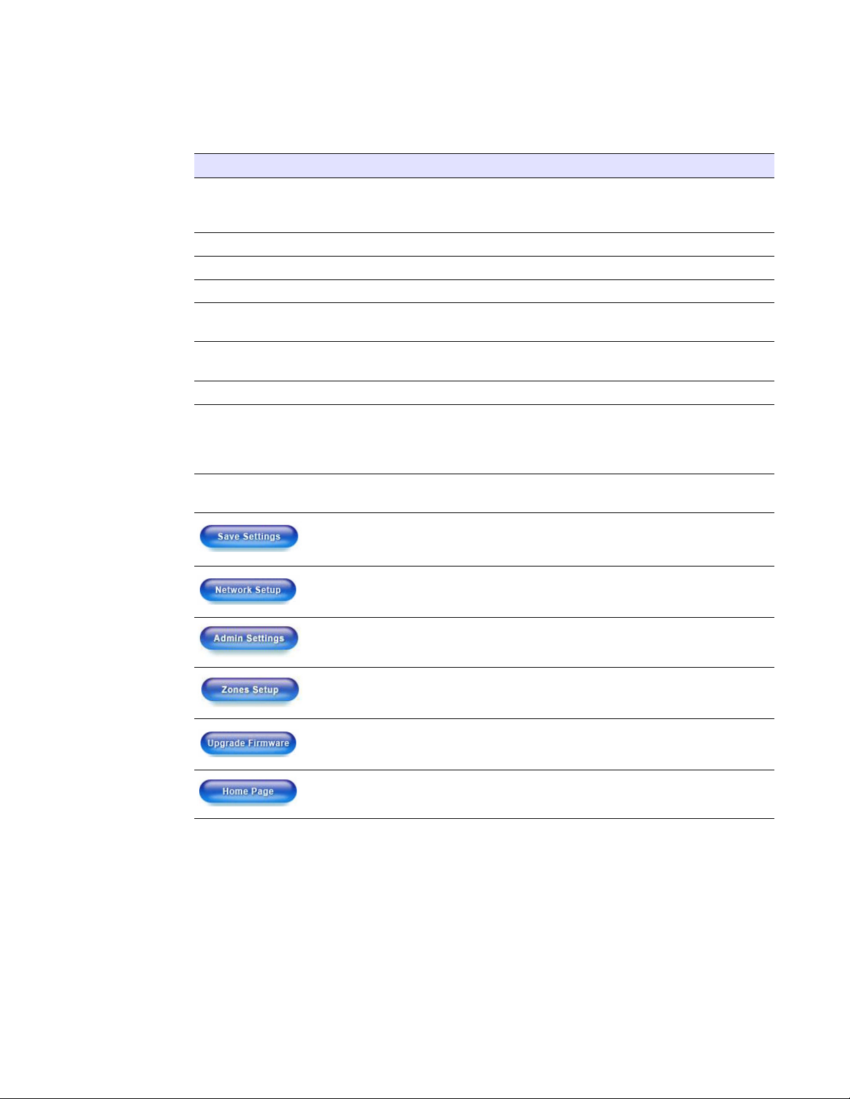
Link to the Network Setup web page.
Link to the Admin Settings web page.
Link to the Zones Setup web page.
Link to the Upgrade Firmware web page.
Link to the Home page.
1. Enter the IP address of the SIP Server.
2. Enter the port numbers used for SIP signaling:
a. Remote SIP Port
b. Local SIP Port
CyberData Corporation 930109C VoIP Zone Controller 4-Port Audio Out Operations Guide
Page 23

Implementing the VoIP Zone Controller
Configuring the VoIP Zone Controller
3. Enter the SIP registration parameters:
a. SIP User ID
b. Authenticate ID
c. Authenticate Password
4. For SIP Registration, designate whether you want the VoIP Zone Controller to register with
your SIP server.
5. At Unregister on Reboot:
a. Select Yes to automatically unregister the VoIP Zone Controller when you reboot it. Section
2.8, "Rebooting the VoIP Zone Controller" provides instructions on that process.
b. Select No to keep the VoIP Zone Controller registered when you reboot it.
6. In the Register Expiration field, enter the number of minutes the VoIP Zone Controller
registration lease remains valid with the SIP Server. The VoIP Zone Controller automatically reregisters with the SIP server before the lease expiration timeout.
17
VoIP Zone Controller 4-Port Audio Out Operations Guide 930109C CyberData Corporation
Page 24
18
Implementing the VoIP Zone Controller
Set up the Zones
2.5 Set up the Zones
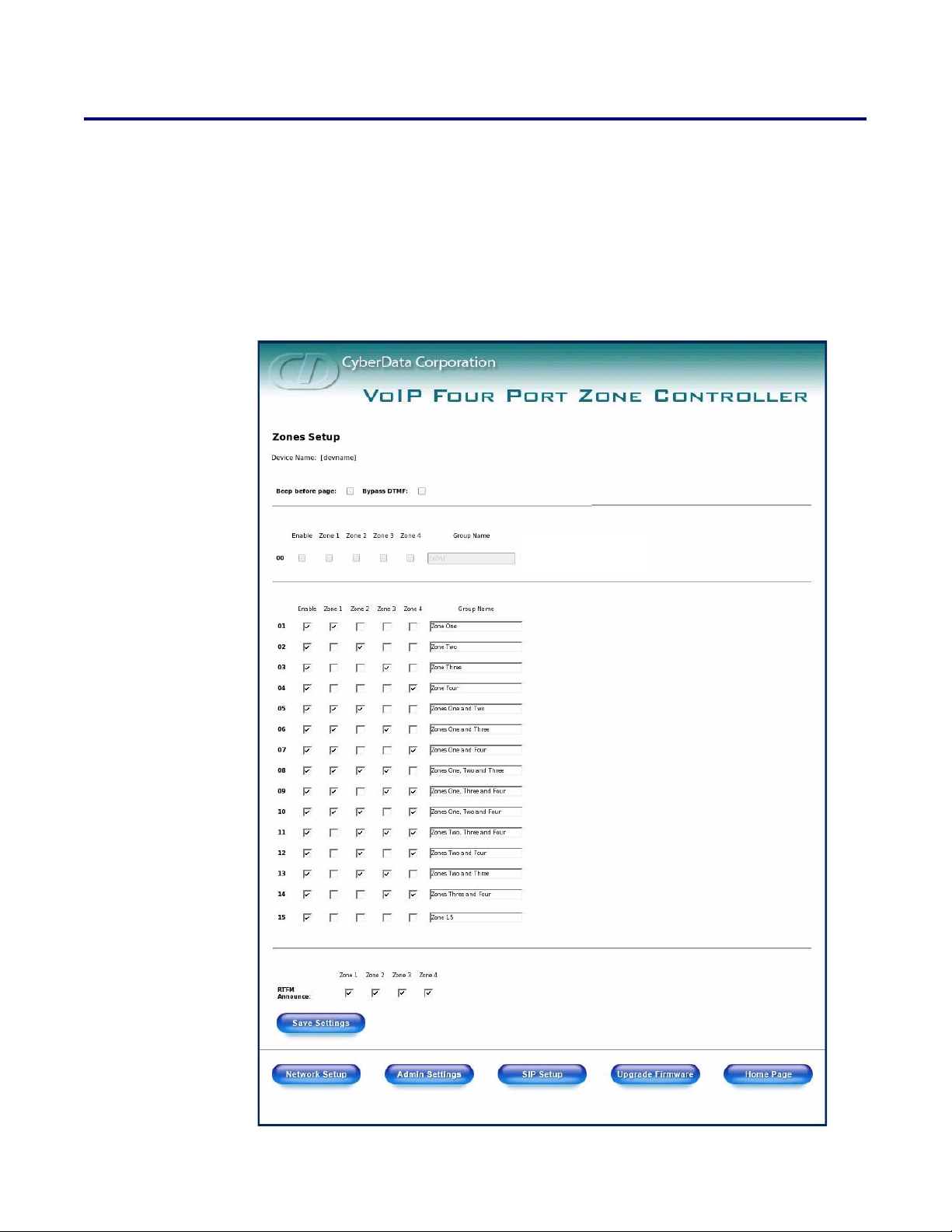
● Each audio output jack on the VoIP Zone Controller represents a Zone.
● A Group is comprised of a combination of one or more Zones.
● You will need to plug any Zones that are used on the VoIP Zone Controller into an analog
amplifier. Any speakers attached to the amplifier will be present in the Zone.
1. Click on the Zones Setup button to open the Zones Setup page. See Figure 2-10.
Figure 2-10. Zones Setup
CyberData Corporation 930109C VoIP Zone Controller 4-Port Audio Out Operations Guide
Page 25
Implementing the VoIP Zone Controller
Set up the Zones
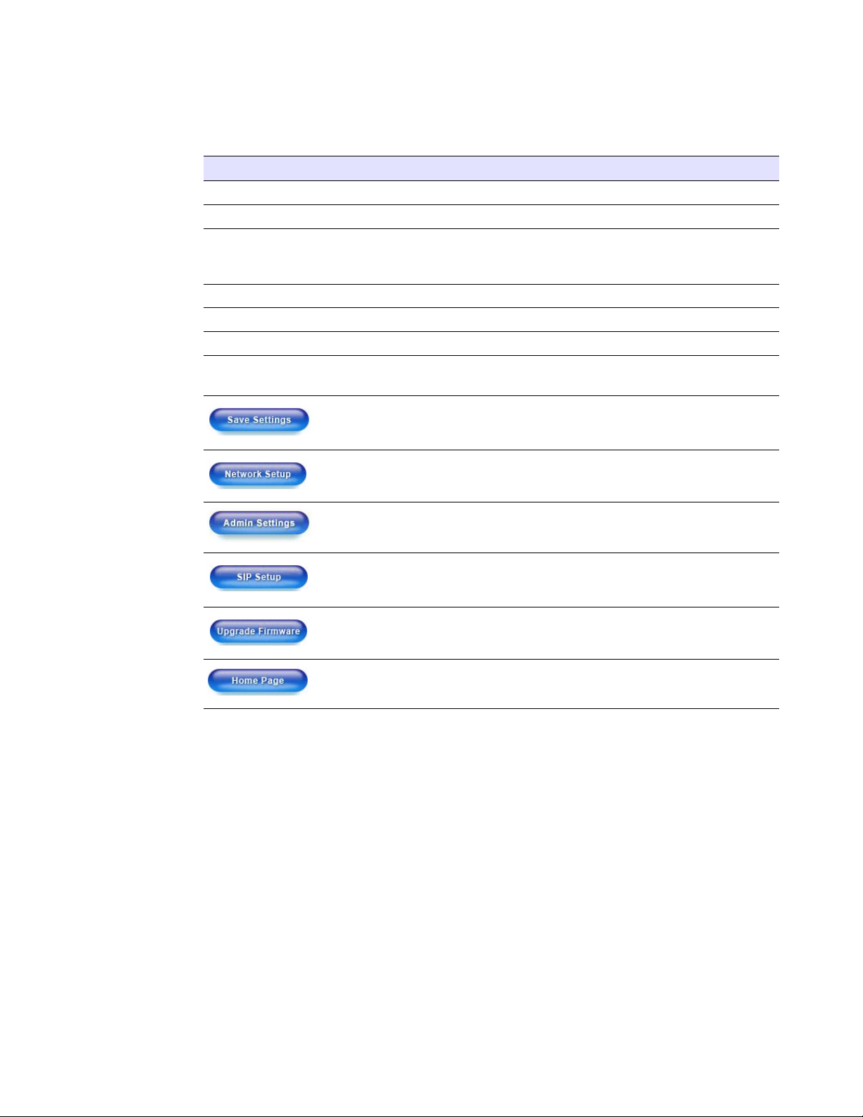
2. On the Zones Setup page, enter values for the parameters indicated in Ta b l e 2-5.
Table 2-5. Zones Setup Parameters
Web Page Item Description
Device Name Shows the name of the device.
Beep Before Page Check this box to play a beep before a page is sent.
Bypass DTMF Check this box to send a page without having to enter a two-
digit tone. When enabled, all four zones will be paged without
waiting for DTMF entry.
Enable Check this box to enable the Group.
Zones 1-4 Checkboxes Check the box for the Zones that should comprise this Group.
Group Name Assign an identifier to the Group.
RTFM Announce Check the box for the Zone that you want to hear a RTFM
announcement from.
Click on this button to save your configuration settings.
Changing a parameter that has an asterisk next to it will cause
a system reboot when saved.
Link to the Network Setup web page.
19
Link to the Admin Settings web page.
Link to the SIP Setup web page.
Link to the Upgrade Firmware web page.
Link to the Home page.
3. After changing the parameters, click Save Settings.
VoIP Zone Controller 4-Port Audio Out Operations Guide 930109C CyberData Corporation
Page 26
20
Implementing the VoIP Zone Controller
Operating the VoIP Zone Controller
2.6 Operating the VoIP Zone Controller
● When you call to make a page, the VoIP Zone Controller generates a tone over the phone.
● When you hear this tone, enter the two-digit code for the group that you want to page.
● The VoIP Zone Controller establishes a connection to a group.
● The VoIP Zone Controller generates another tone to the phone.
● When you hear this tone, you can begin speaking.
Note Group 00 is configured to Page All Zones.
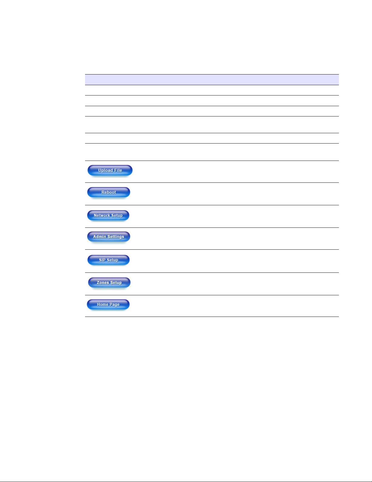
2.7 Upgrading the Firmware
The firmware on the board consists of two files: a Kernel and an Application, that can be loaded
separately. Uploading the firmware files requires a host machine running a TFTP server. If you need
to set up this server,
"Appendix A: Setting Up a TFTP Server" provides instructions.
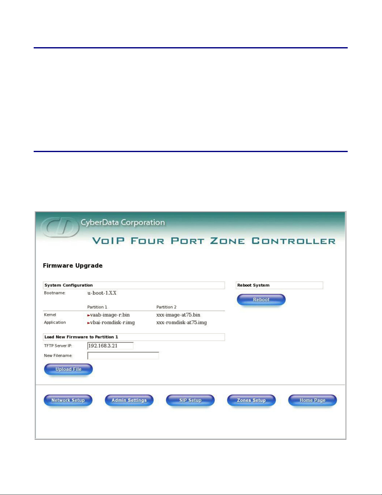
Figure 2-11. Firmware Upgrade Page
CyberData Corporation 930109C VoIP Zone Controller 4-Port Audio Out Operations Guide
Page 27
Implementing the VoIP Zone Controller
Upgrading the Firmware
To upload a firmware file, log in as instructed in Section 2.4.2, "Log in to the Configuration GUI".
Ta bl e 2-6 shows the web page items on the Firmware Upgrade page.
Table 2-6. Firmware Upgrade Parameters
Web Page Item Description
System Configuration Shows the current configuration.
Bootname Shows the current boot loader filename.
Kernel Shows the current kernel filename for partition 1 and 2.
Application Shows the current application filename for partition 1
and 2.
TFTP Server IP address Enter the TFTP Server IP address.
New Filename Use this field to enter the new file name for the kernel or
application firmware file that you are uploading.
Click on this button to automatically upload the selected
firmware and reboot the system.
Click on this button to reboot the system.
21
Link to the Network Setup web page.
Link to the Admin Settings web page.
Link to the SIP Setup web page.
Link to the Zones Setup web page.
Link to the Home page.
1. On the Home page, click Upgrade Firmware to open the Firmware Upgrade page.
2. Enter the TFTP Server IP address.
3. Enter the Kernel or Application New Filename for the firmware file you are uploading.
4. Select the Partition to which the firmware is uploaded.
5. Click Upload File to automatically upload the selected firmware, and reboot your system.
VoIP Zone Controller 4-Port Audio Out Operations Guide 930109C CyberData Corporation
Page 28
22
Implementing the VoIP Zone Controller
Rebooting the VoIP Zone Controller
2.8 Rebooting the VoIP Zone Controller
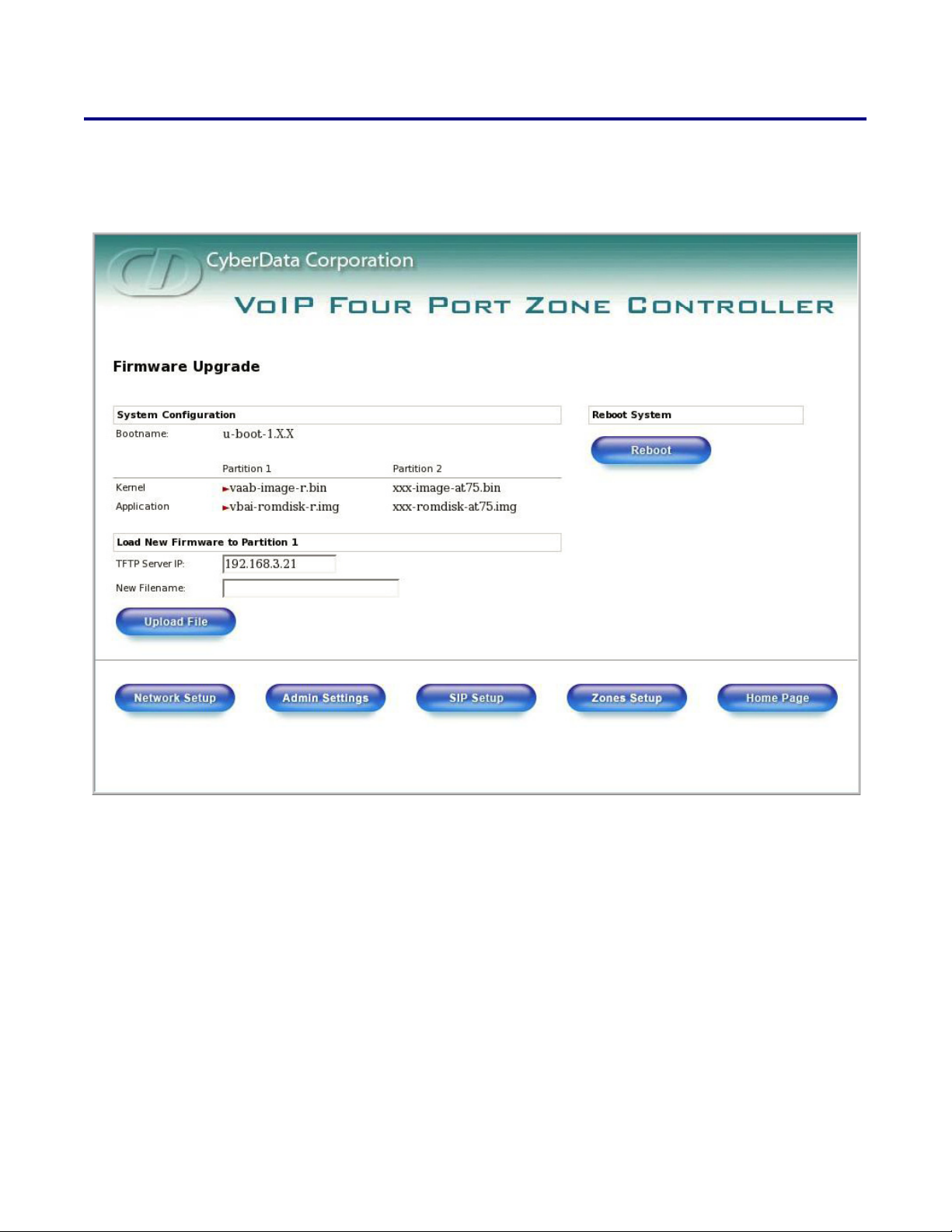
To reboot the system, log in as instructed in Section 2.4.2, "Log in to the Configuration GUI".
Figure 2-12. Firmware Upgrade Page
1. On the Home page, click Upgrade Firmware to open the Firmware Upgrade page. Go to the
Reboot section on the right side of the page.
2. Click Reboot.
CyberData Corporation 930109C VoIP Zone Controller 4-Port Audio Out Operations Guide
Page 29

Appendix A: Setting Up a TFTP Server
Upgrading the firmware requires a TFTP server on which you access the Web interface where you
upload the firmware files.
A.1 Set up a TFTP Server
Upgrading the VoIP Zone Controller firmware requires a TFTP server on which you access the Web
interface where you can upload the firmware files.
A.1.1 In a Linux Environment
To set up a TFTP server on LINUX:
1. Create a directory dedicated to the TFTP server, and move the files to be uploaded to that
directory.
23
2. Run the following command where /tftpboot/ is the path to the directory you created in
Step 1: the directory that contains the files to be uploaded. For example:
in.tftpd -l -s /tftpboot/your_directory_name
A.1.2 In a Windows Environment
You can find several options online for setting up a Windows TFTP server. This example explains
how to use the Solarwinds freeware TFTP server, which you can download at:
http://www.cyberdata.net/support/voip/solarwinds.html
To set up a TFTP server on Windows:
1. Install and start the software.
2. Select File/Configure/Security tab/Tr an sm i t O nly.
3. Make a note of the default directory name, and then move the firmware files to be uploaded to
that directory.
VoIP Zone Controller 4-Port Audio Out Operations Guide 930109C CyberData Corporation
Page 30

24
Set up a TFTP Server
CyberData Corporation 930109C VoIP Zone Controller 4-Port Audio Out Operations Guide
Page 31

Appendix B: Troubleshooting/Technical Support
B.1 Frequently Asked Questions (FAQ)
Go to the following URL to see CyberData’s list of frequently asked questions:
http://www.cyberdata.net/products/voip/legacyanalog/pagingzone4portaudio/faqs.html
B.1.1 Documentation
The documentation for this product is released in an English language version only. You can
download PDF copies of CyberData product documentation at:
http://www.cyberdata.net/products/voip/legacyanalog/pagingzone4portaudio/docs.html
25
B.2 Contact Information
Contact
Sales
Technical Support
Returned Materials Authorization
CyberData Corporation
2555 Garden Road
Monterey, CA 93940
USA
www.CyberData.net
Phone: 800-CYBERDATA (800-292-3732)
Fax: 831-373-4193
Sales 831-373-2601 Extension 334
Phone: 831-373-2601 Extension 333
Web: http://www.cyberdata.net/support/contactsupportvoip.html
To return the product, contact the CyberData Returned Materials Authorization (RMA) department
at:
Phone: 831-373-2601, Extension 136
Email: [email protected]
When returning a product to CyberData, an approved CyberData RMA number must be printed on
the outside of the original shipping package. No product will be accepted for return without an
approved RMA number. Send the product, in its original package, to the following address:
CyberData Corporation
2555 Garden Road
Monterey, CA 93940
Attention: RMA "your RMA number"
VoIP Zone Controller 4-Port Audio Out Operations Guide 930109C CyberData Corporation
Page 32

26
Warranty
RMA Status Form
If you need to inquire about the repair status of your product(s), please use the CyberData RMA
Status form at the following web address:
http://www.cyberdata.net/support/rmastatus.html
B.3 Warranty
CyberData warrants its product against defects in material or workmanship for a period of two
years from the date of purchase. Should the product fail within the warranty period, CyberData will
repair or replace the product free of charge. This warranty includes all parts and labor.
Should the product fail out-of-warranty, a flat rate repair charge of one half of the purchase price of
the product will be assessed. Repairs that are in warranty but are damaged by improper
modifications or abuse, will be charged at the out-of-warranty rate. Products shipped to CyberData,
both in and out-of-warranty, are shipped at the expense of the customer. Shipping charges for
repaired products shipped back to the customer by CyberData, will be paid by CyberData.
CyberData shall not under any circumstances be liable to any person for any special, incidental,
indirect or consequential damages, including without limitation, damages resulting from use or
malfunction of the products, loss of profits or revenues or costs of replacement goods, even if
CyberData is informed in advance of the possibility of such damages.
B.3.1 Warranty & RMA Returns within the United States
If service is required, you must contact CyberData Technical Support prior to returning any
products to CyberData. Our Technical Support staff will determine if your product should be
returned to us for further inspection. If Technical Support determines that your product needs to be
returned to CyberData, an RMA number will be issued to you at this point.
Your issued RMA number must be printed on the outside of the shipping box. No product will be
accepted for return without an approved RMA number. The product in its original package should
be sent to the following address:
CyberData Corporation
2555 Garden Rd.
Monterey, CA 93940
Attn: RMA "xxxxxx"
B.3.2 Warranty & RMA Returns Outside of the United States
If you purchased your equipment through an authorized international distributor or reseller, please
contact them directly for product repairs.
CyberData Corporation 930109C VoIP Zone Controller 4-Port Audio Out Operations Guide
Page 33

B.3.3 Spare in the Air Policy
CyberData now offers a Spare in the Air no wait policy for warranty returns within the United States
and Canada. More information about the Spare in the Air policy is available at the following web
address:
http://www.cyberdata.net/support/warranty/spareintheair.html
B.3.4 Return and Restocking Policy
For our authorized distributors and resellers, please refer to your CyberData Service Agreement for
information on our return guidelines and procedures.
For End Users, please contact the company that you purchased your equipment from for their
return policy.
B.3.5 Warranty and RMA Returns Page
27
Warranty
The most recent warranty and RMA information is available at the CyberData Warranty and RMA
Returns Page at the following web address:
http://www.cyberdata.net/support/warranty/index.html
VoIP Zone Controller 4-Port Audio Out Operations Guide 930109C CyberData Corporation
Page 34

28
Warranty
CyberData Corporation 930109C VoIP Zone Controller 4-Port Audio Out Operations Guide
Page 35

Index
29
Symbols
+48V DC power supply 5
Numerics
100 Mbps indicator light 6
A
act light 6
address, login 8
addressing
DHCP 8, 12
static 8, 12
admin settings button 13
admin username and password 9
administrator settings page 13
asterisk 11, 13, 16, 19
authenticate ID and password for SIP server
registration 17
CyberData contact information 25
D
default
gateway 7
IP address 7
subnet mask 7
username and password 7
default gateway 7, 11
default gateway for static addressing 12
default password for configuration GUI 9
default settings, restoring 7
default username and password for configuration GUI 9
DHCP addressing 8, 12
DHCP IP addressing 11
dimensions 2
DNS server 9, 11
dual speeds 6
E
enable feature 19
ethernet port 5
B
baud rate
specification 2
verifying 6
beep before page 19
blue status light 6
bypass DTMF 19
expiration time for SIP server lease 16, 17
F
features 1
firmware upgrade page 21, 22
firmware upgrades 23
firmware, upgrade 10, 20
C
cat 5 ethernet cable 5
changing default username and password for
configuration GUI 13
configurable parameters 9, 11, 16, 21
configuration information 8
contact information 25
contact information for CyberData 25
current settings, reviewing 10
Operations Guide 930109C CyberData Corporation
G
green link light 6
green paging light 6
Group 18
GUI username and password 13
Page 36

30
I
IP address 7, 11, 21
SIP server 16
IP addressing 11
default
IP addressing setting 7
L
lease, SIP server expiration time 16, 17
link light 6
Linux, setting up a TFTP server on 23
local SIP port 16
log in address 8
logging in to configuration GUI 8
N
network activity, verifying 6
network configuration page 10
network parameters, configuring 10
network setup button 10
network, connecting to 5
O
orange link light 6
P
paging light 6
part number 2
parts list 3
password
configuration GUI 8, 13
for SIP server login 16
restoring the default 7
SIP server authentication 17
pgroups configuration 10
port
ethernet 5
local SIP 16
remote SIP 16
power
connecting to 5
requirement 2
product overview 1
R
reboot 21
unregistering from SIP server during 17
zone controller 22
registration and expiration, SIP server
lease expiration 17
registration and expiration, SIP server lease 16
regulatory compliance 2
remote SIP port 16
required configuration for web access username and
password 8, 14
requirements for upgrading firmware 20
resetting the IP address to the default 25
restoring factory default settings 7
return and restocking policy 27
RMA returned materials authorization 25
RMA status 26
RTFM switch 7
S
sales 25
server
SIP 10
TFTP 20, 23
server address, SIP 16
service 25
setting up a TFTP server 23
SIP configuration
SIP Server 16
SIP configuration page 14
SIP registration 16
SIP server 16
SIP server configuration 10
SIP server parameters, configuring 8
SIP setup button 10, 14
Spare in the Air Policy 27
speaker configuration page
configurable parameters 9, 11, 16, 21
specifications 2
static addressing 8, 12
static IP addressing 11
status light 6
subnet mask 7, 11
subnet mask static addressing 12
supported protocols 2
T
tech support 25
technical support, contact information 25
CyberData Corporation 930109C Operations Guide
Page 37

31
TFTP server 20, 23
TFTP server IP 21
U
unregister from SIP server 17
unregister, from SIP server 16
upgrade firmware 10, 20
upgrade firmware button 10, 21, 22
upload file button 21
user ID
for SIP server login 16
user ID for SIP server registration 17
user ID, SIP 16
username
restoring the default 7
username for configuration GUI 8, 13
V
verifying
baud rate 6
network activity 6
network connectivity 6
beep before page 19
bypass DTMF 19
enable feature 19
zones checkboxes 19
zones checkboxes 19
W
warranty 26
warranty & RMA returns outside of the United States 26
warranty & RMA returns within the United States 26
warranty and RMA returns page 27
warranty policy at CyberData 26
web configuration log in address 8
weight 2
Windows, setting up a TFTP server on 23
Y
yellow act light 6
yellow link light 6
Z
Zone 18
zone controller
configuration 8
zone setup
Operations Guide 930109C CyberData Corporation
Page 38

32
CyberData Corporation 930109C Operations Guide
 Loading...