

Page 1
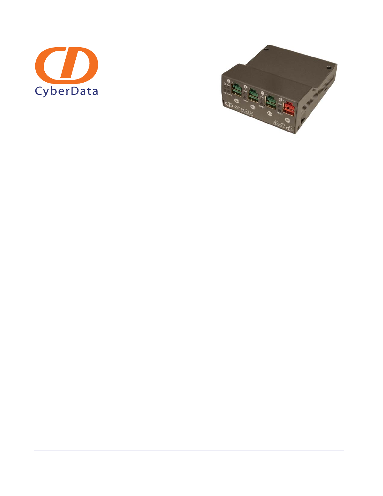
4-Port PoweredUSB 2.0 Hub
Operations Guide
with External Power Supply
Part #010807
930103E
CyberData Corporation
2555 Garden Road
Monterey, CA 93940
(831) 373-2601
Page 2

4-Port PoweredUSB 2.0 Hub Operations Guide 930103E
Phone: (831) 373-2601
Technical Support Ext. 333
[email protected]
Fax: (831) 373-4193
Company and product information at www.cyberdata.net
Part # 010807
COPYRIGHT NOTICE:
© 2009, CyberData Corporation, ALL RIGHTS RESERVED.
This manual and related materials are the copyrighted property of CyberData Corporation. No part
of this manual or related materials may be reproduced or transmitted, in any form or by any means
(except for internal use by licensed customers), without prior express written permission of
CyberData Corporation. This manual, and the products, software, firmware, and/or hardware
described in this manual are the property of CyberData Corporation, provided under the terms of an
agreement between CyberData Corporation and recipient of this manual, and their use is subject to
that agreement and its terms.
DISCLAIMER: Except as expressly and specifically stated in a written agreement executed by
CyberData Corporation, CyberData Corporation makes no representation or warranty, express or
implied, including any warranty or merchantability or fitness for any purpose, with respect to this
manual or the products, software, firmware, and/or hardware described herein, and CyberData
Corporation assumes no liability for damages or claims resulting from any use of this manual or
such products, software, firmware, and/or hardware. CyberData Corporation reserves the right to
make changes, without notice, to this manual and to any such product, software, firmware, and/or
hardware.
OPEN SOURCE STATEMENT: Certain software components included in CyberData products are
subject to the GNU General Public License (GPL) and Lesser GNU General Public License (LGPL)
“open source” or “free software” licenses. Some of this Open Source Software may be owned by
third parties. Open Source Software is not subject to the terms and conditions of the CyberData
COPYRIGHT NOTICE or software licenses. Your right to copy, modify, and distribute any Open
Source Software is determined by the terms of the GPL, LGPL, or third party, according to who
licenses that software.
Software or firmware developed by CyberData that is unrelated to Open Source Software is
copyrighted by CyberData, subject to the terms of CyberData licenses, and may not be copied,
modified, reverse-engineered, or otherwise altered without explicit written permission from
CyberData Corporation.
TRADEMARK NOTICE: CyberData Corporation and the CyberData Corporation logos are
trademarks of CyberData Corporation. Other product names, trademarks, and service marks may be
the trademarks or registered trademarks of their respective owners.
CyberData Corporation 930103E Operations Guide
Page 3

Contents
Chapter 1 Product Overview 1
1.1 Product features .....................................................................................................................................1
1.2 License note ............................................................................................................................................. 2
1.3 Documentation note ..............................................................................................................................2
1.4 Dimensions .............................................................................................................................................3
Chapter 2 Installing and Using the 4-Port PoweredUSB Hub 4
2.1 Product Components List .....................................................................................................................5
2.2 Product Compatibility ...........................................................................................................................6
2.3 Installation ...............................................................................................................................................6
2.4 Connections ............................................................................................................................................7
2.5 Operation ...............................................................................................................................................14
2.6 Port Electrical Specifications ..............................................................................................................15
i
2.4.1 Power Supply ..............................................................................................................................7
2.4.2 Host Connector ............................................................................................................................8
2.4.3 PoweredUSB Connections .........................................................................................................8
2.4.4 Connector Color Keys ................................................................................................................9
2.4.5 Peripherals Connections to the SiP VoIP and PoE Speaker ................................................10
2.4.6 Peripheral Cable Connection Options ................................................................................... 11
2.5.1 POS Peripheral Caveat .............................................................................................................14
2.6.1 Standard USB lower A supply ................................................................................................15
2.6.2 PoweredUSB supply .................................................................................................................15
Appendix A Regulatory and Safety Information 16
Appendix B Setting up the Hub on Windows XP 17
Appendix C Troubleshooting/Technical Support 18
C.1 Frequently Asked Questions (FAQ) .................................................................................................18
C.2 Documentation ....................................................................................................................................18
C.3 Contact Information ............................................................................................................................18
C.4 Warranty ...............................................................................................................................................19
Index 20
Operations Guide 930103E CyberData Corporation
Page 4
1 Product Overview
The SiP VoIP and PoE Speaker provides a simple, affordable way to add up to four PoweredUSB
ports to your PC. These additional ports are controlled by the PC’s Standby and Wake commands.
This add-on Hub makes it easy to connect the PC to devices that require more than the 500mA of +5
volts supplied with the standard USB interface.
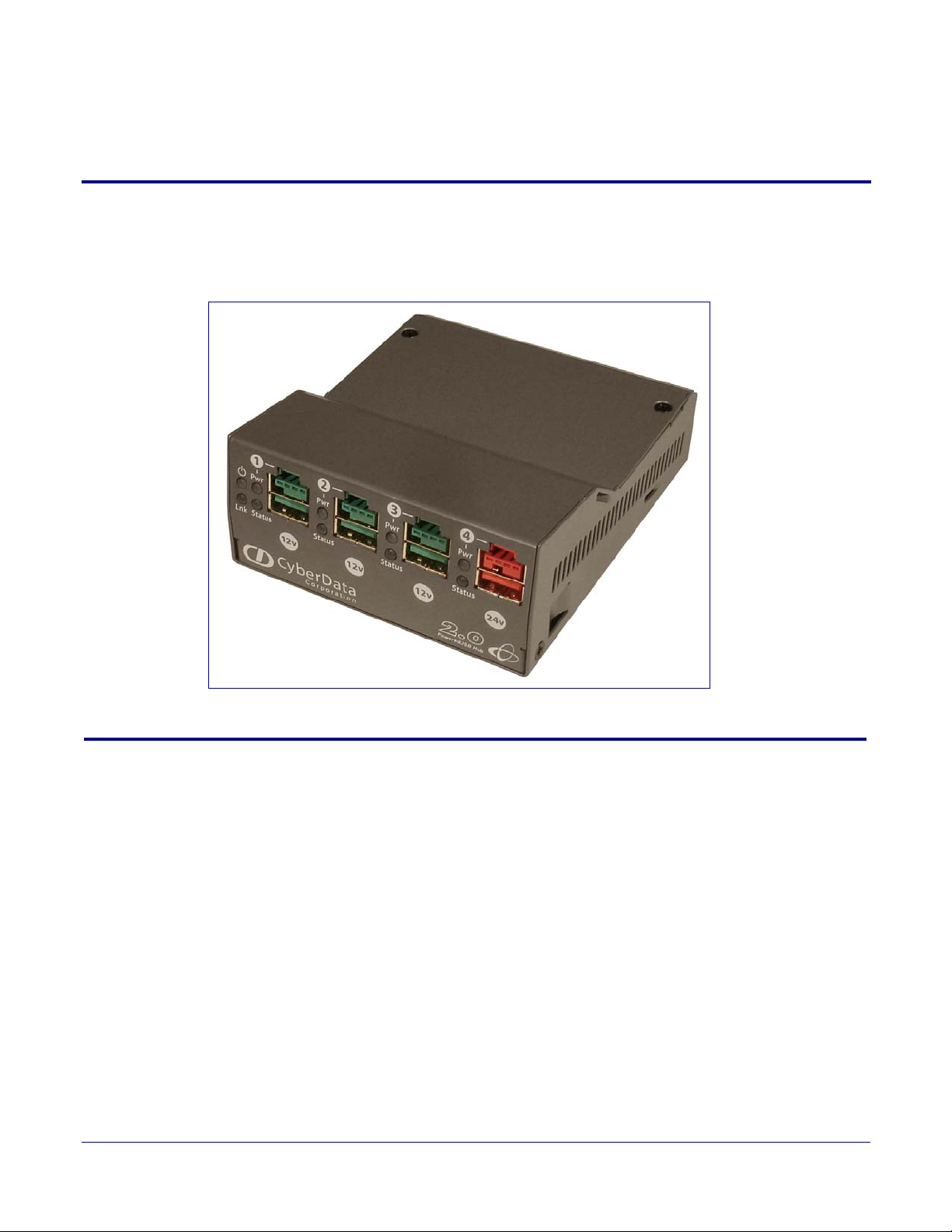
Figure 1-1. CyberData 4-Port PoweredUSB 2.0 Hub
1
1.1 Product features
● 4 PoweredUSB ports
● One +24 volt up to 2.3A
● Three +12 volt up to 1.5A each
● Short circuit and over current protected
● Multiple power supply options
● Plug-n-Play installation
● Peripheral power controlled by PC stand-by and wake commands
● LED indicators for port power output and USB 2.0 status
● Two-year warranty
Operations Guide 930103E CyberData Corporation
Page 5

1.2 License note
The PoweredUSB controller board contains certain technology that is covered by an IBM® patent.
CyberData Corporation is licensed with IBM to manufacture, and to sell or lease products that
incorporate this technology. This license also permits other entities to resell or release these
Cyberdata products after they have been purchased from CyberData.
1.3 Documentation note
The documentation for this product is released in an English language version only.
Product Overview
License note
2
Operations Guide 930103E CyberData Corporation
Page 6
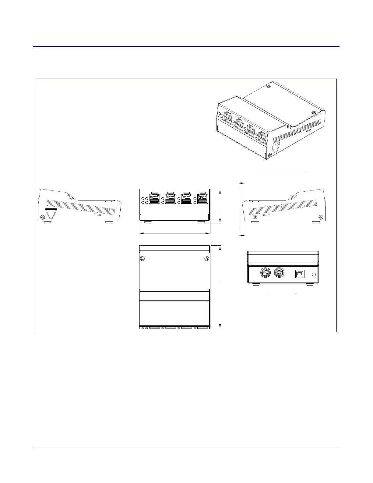
1.4 Dimensions
A
A
View A-A
Rear View
Dimensions are in Inches [Millimeter]
Perspective View
1.78
[45.3]
3.71
[94.3]
4.34
[110.3]
Figure 1-2. Dimensions
Product Overview
Dimensions
3
Operations Guide 930103E CyberData Corporation
Page 7
2 Installing and Using the 4-Port PoweredUSB Hub
This chapter provides the instructions, illustrations, and background information you need to
install, and begin working with the SiP VoIP and PoE Speaker.
● Section 2.1, "Product Components List"
● Section 2.2, "Product Compatibility"
● Section 2.3, "Installation"
● Section 2.4, "Connections"
● Section 2.5, "Operation"
● Section 2.6, "Port Electrical Specifications"
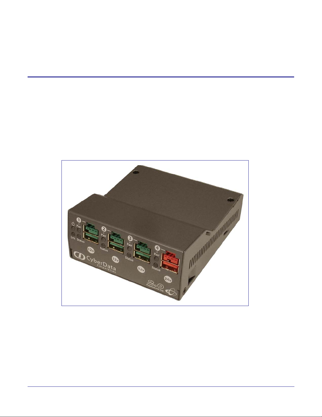
Figure 2-3. CyberData 4-Port PoweredUSB 2.0 Hub
4
Operations Guide 930103E CyberData Corporation
Page 8
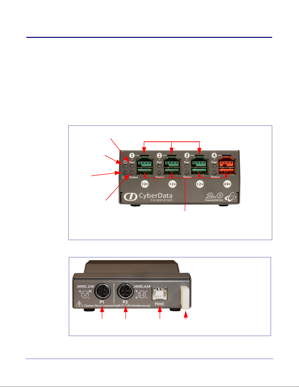
2.1 Product Components List
Port Power LED +12V PoweredUSB Ports
Hub Power LED
Link LED
Port 1 Status LED
Lower portion of PoweredUSB Port connectors are
Standard USB 2.0 Hi-Speed “A” ports
+24V for
up to 2.5
Amp load
+24V for
up to 6.5
Amp load
USB Host
Connector
(Type B)
Strain
Relief
The 4-Port PoweredUSB 2.0 Hub package includes these parts:
● (1) SiP VoIP and PoE Speaker
● Power Supply, 24VDC, Desk-top, 4-Pin Hosiden style plug
● (1) Accessory Kit
• (1) Short USB 2.0 Hi-Speed host cable
• (1) Host USB cable strain relief clamp
•(1) 4-Port PoweredUSB 2.0 Hub Operations Guide
Figure 2-4. CyberData 4-Port PoweredUSB 2.0 Hub—Front View
Installing and Using the 4-Port PoweredUSB Hub
Product Components List
5
Figure 2-5. CyberData 4-Port PoweredUSB 2.0 Hub—Back View
Operations Guide 930103E CyberData Corporation
Page 9

2.2 Product Compatibility
The SiP VoIP and PoE Speaker is compatible with the following operating systems and USB
standards.
Ta ble 2-1. Operating Systems
Operating systems USB
Windows 2000 and XP 2.0 Standard
LINUX PoweredUSB 0.8g
Mac OS-X
2.3 Installation
The SiP VoIP and PoE Speaker is a tabletop unit with mounting feet that sit on a flat surface.
Installing and Using the 4-Port PoweredUSB Hub
Product Compatibility
6
Operations Guide 930103E CyberData Corporation
Page 10
2.4 Connections
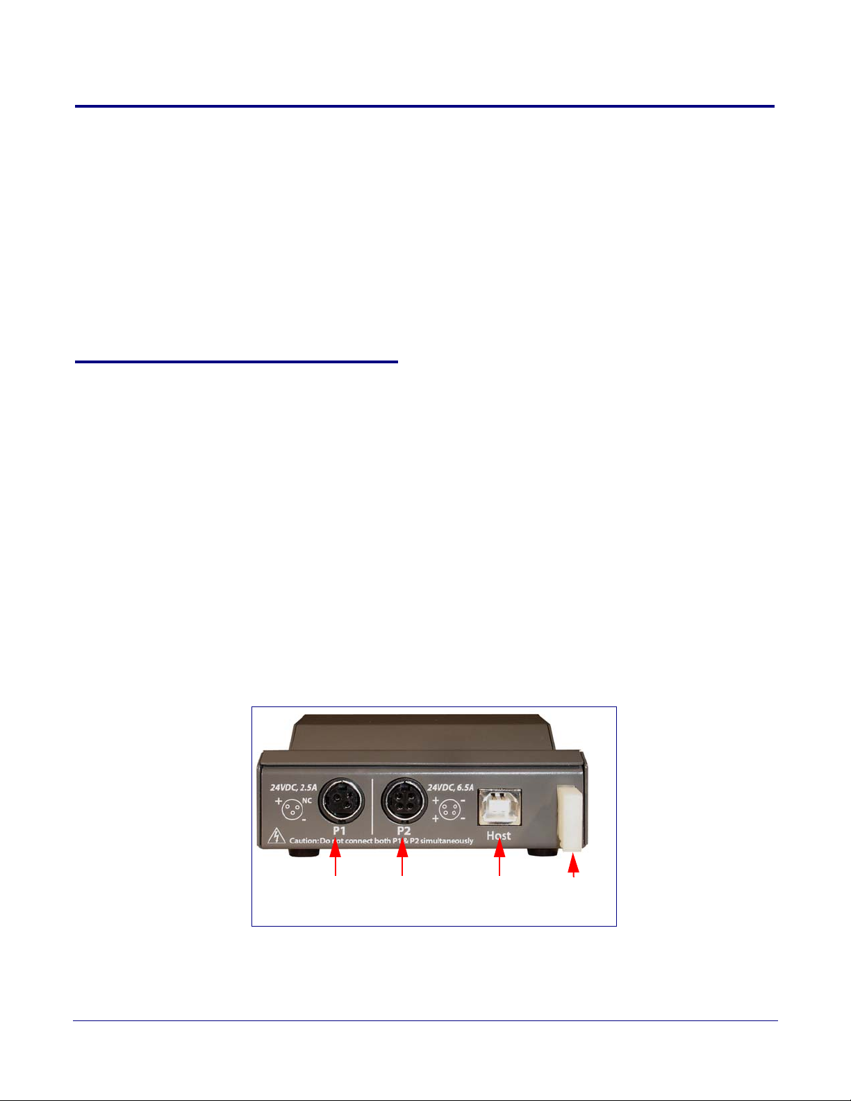
+24V for
up to 2.5
Amp load
+24V for
up to 6.5
Amp load
USB Host
Connector
(Type B)
Strain
Relief
This following topics provide illustrations and information on connecting the SiP VoIP and PoE
Speaker to power supplies, the host, and peripheral devices.
● Section 2.4.1, "Power Supply"
● Section 2.4.2, "Host Connector"
● Section 2.4.3, "PoweredUSB Connections"
● Section 2.4.4, "Connector Color Keys"
● Section 2.4.5, "Peripherals Connections to the SiP VoIP and PoE Speaker"
● Section 2.4.6, "Peripheral Cable Connection Options"
2.4.1 Power Supply
The PoweredUSB specification requires supplying +24V at 2.3A and +12V at 1.5A to each voltage
designated port. These requirements are met only if the power supply has sufficient wattage for this
amount of power.
Installing and Using the 4-Port PoweredUSB Hub
Connections
7
The Epson PS180 brick and Dell printer power supply are examples of lower-cost alternate power
supplies that can be used with this Hub and peripherals requiring less power. Two power plug
receptacles are provided on the back of the SiP VoIP and PoE Speaker to facilitate the use of alternate
power supplies.
The three-pin connector is normally used for the Dell and Epson Bricks. The four-pin connector is
used for a high-current power supply. See
Figure 2-10 for an illustration of cable routing from the
SiP VoIP and PoE Speaker.
CAUTION The P1 and P2 DC input jacks on the back of this Hub are for input only. Do not plug
power supplies into both input jacks simultaneously as equipment damage that might void the
product warranty could occur.
Figure 2-6. Power Connectors—Back View
Operations Guide 930103E CyberData Corporation
Page 11
2.4.2 Host Connector
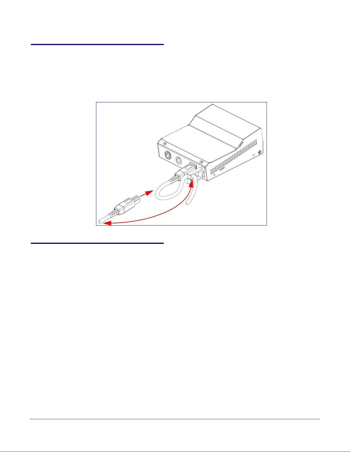
The connection to the host computer is achieved via a standard USB 2.0 certified Hi-Speed “A” to
“B” cable that is included in the Accessory Kit, or with any equivalent USB 2.0 certified Hi-Speed
cable. Refer to the
Installing and Using the 4-Port PoweredUSB Hub
Connections
Section 2.1, "Product Components List" for information about the Accessory Kit.
Figure 2-7. Host connector with strain relief
8
2.4.3 PoweredUSB Connections
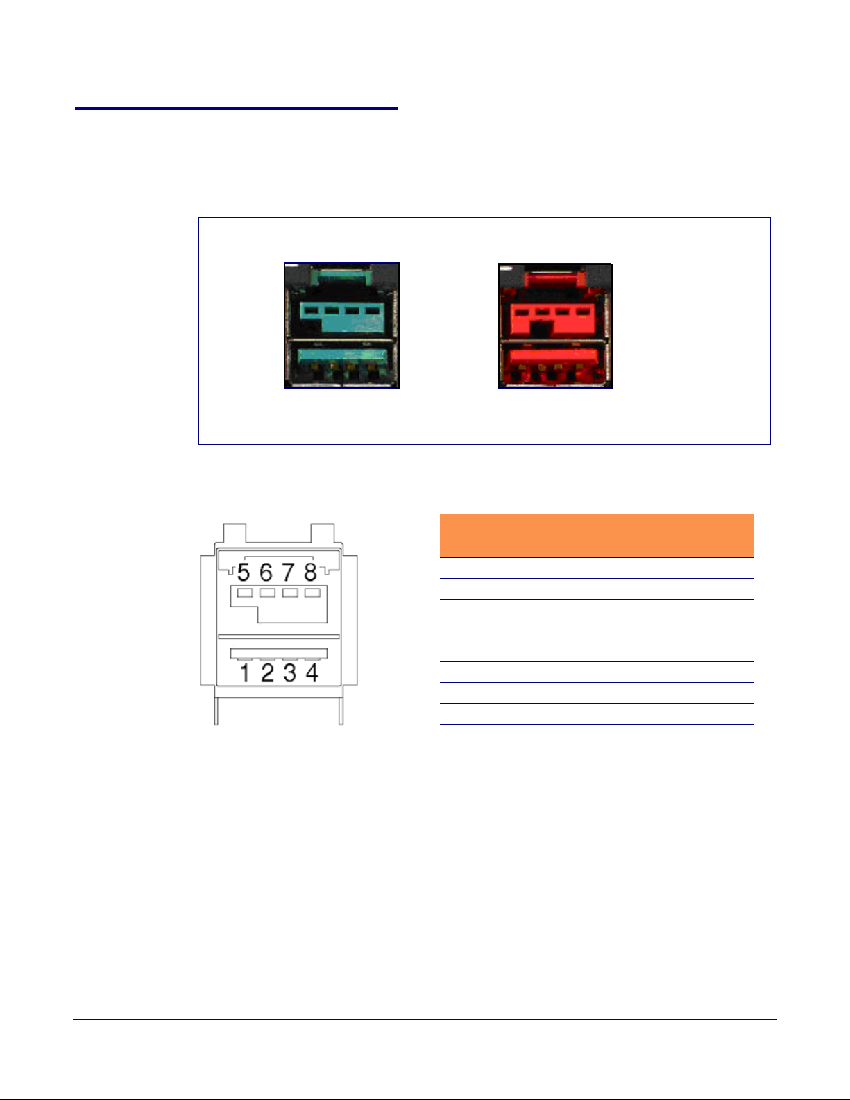
The PoweredUSB connections are standard USB “A” connectors with four extra pins to supply
higher voltages. See
this product can be used alone, without the locking PoweredUSB connector.
Figure 2-9 for an illustration. The lower portion of the “A” connector side on
Operations Guide 930103E CyberData Corporation
Page 12
2.4.4 Connector Color Keys
Teal Red
12 Volt Keyed
1.5A each
Ports 1,2, and 3
24 Volt Keyed
2.3A
Ports 4
PIN OUT
Pin Signal Description
1 Vbus USB standard “A”
2 D- USB standard “A”
3 D+ USB standard “A”
4 Ground USB standard “A”
5 Ground USB PlusPower
6 Vplus USB PlusPower
7 Vplus USB PlusPower
8 Ground USB PlusPower
Shell Shield
The PoweredUSB connectors are color keyed so that only the correct voltage cables can be installed.
Figure 2-8. Color-Coding for Connectors
Installing and Using the 4-Port PoweredUSB Hub
Connections
9
Figure 2-9. USB PoweredUSB Socket Connector Pin Assignments
Operations Guide 930103E CyberData Corporation
Page 13
Installing and Using the 4-Port PoweredUSB Hub
+24V PoweredUSB Connector
+12V PoweredUSB Connectors
CyberData 4-Port PoweredUSB Hub
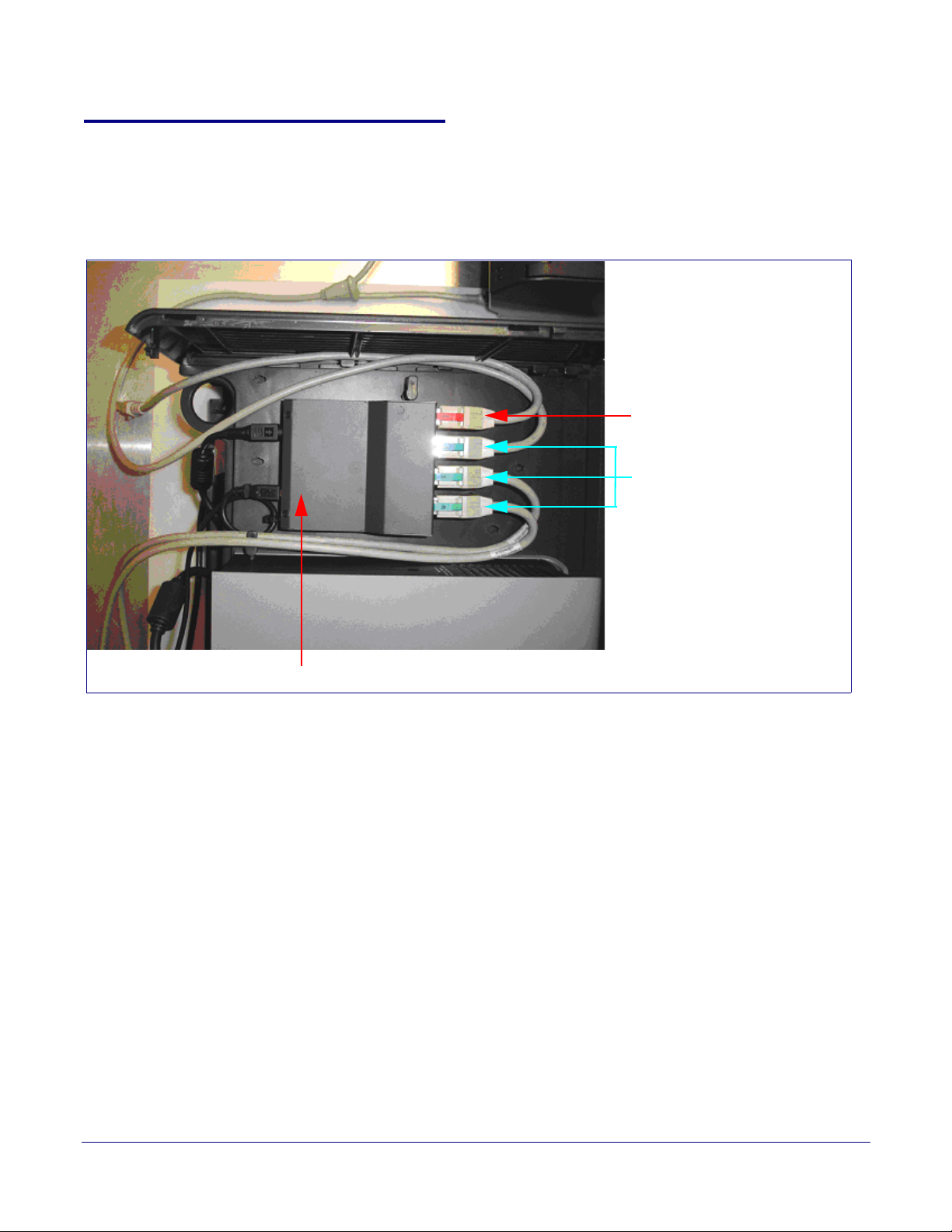
2.4.5 Peripherals Connections to the SiP VoIP and PoE Speaker
This figure illustrates the cable routing from the SiP VoIP and PoE Speaker to the Dell Retail
Integrator.
Figure 2-10. Top view of Hub PoweredUSB cable routing
Connections
10
Operations Guide 930103E CyberData Corporation
Page 14
2.4.6 Peripheral Cable Connection Options
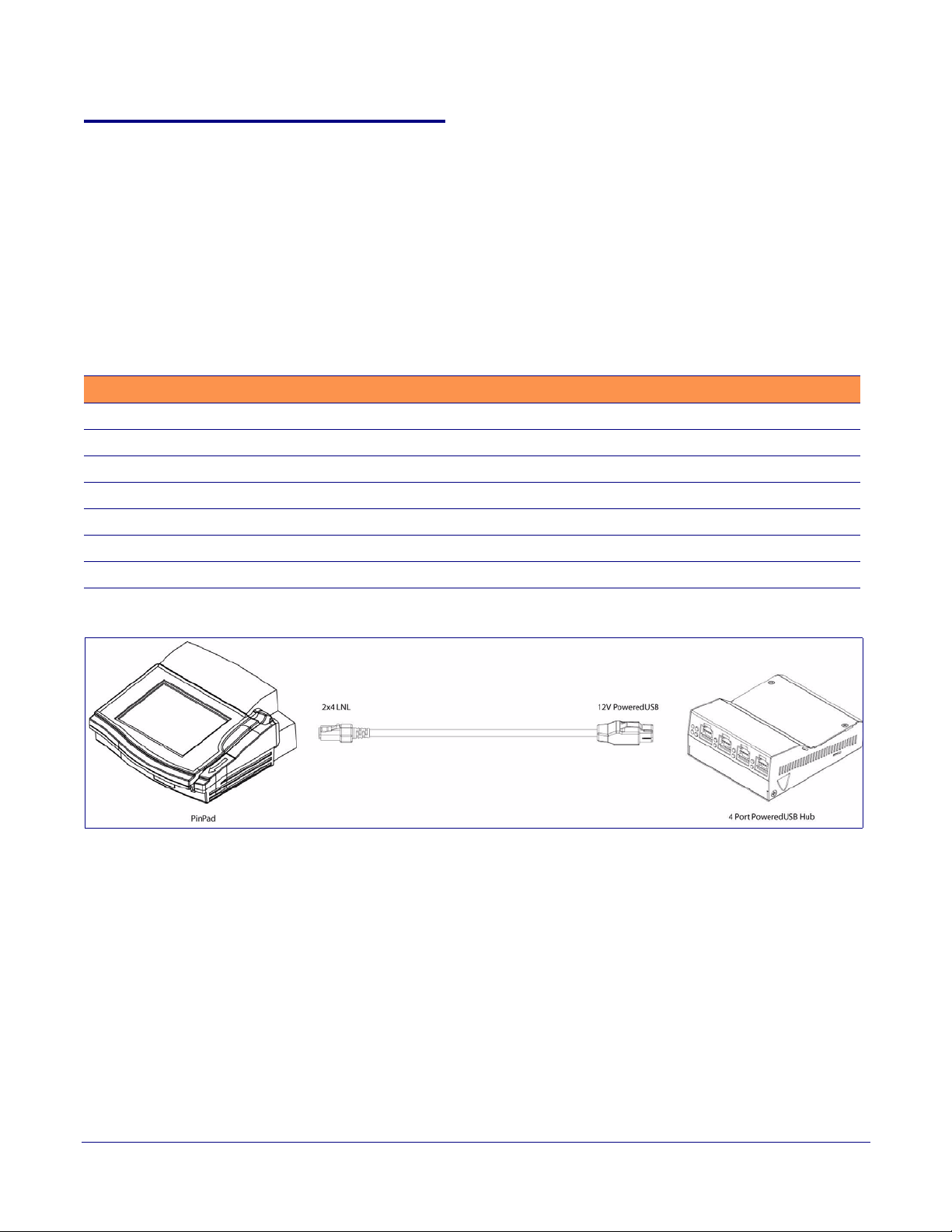
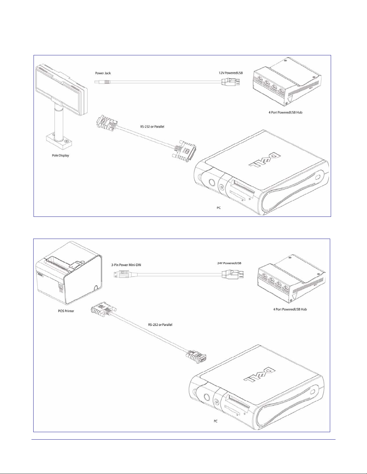
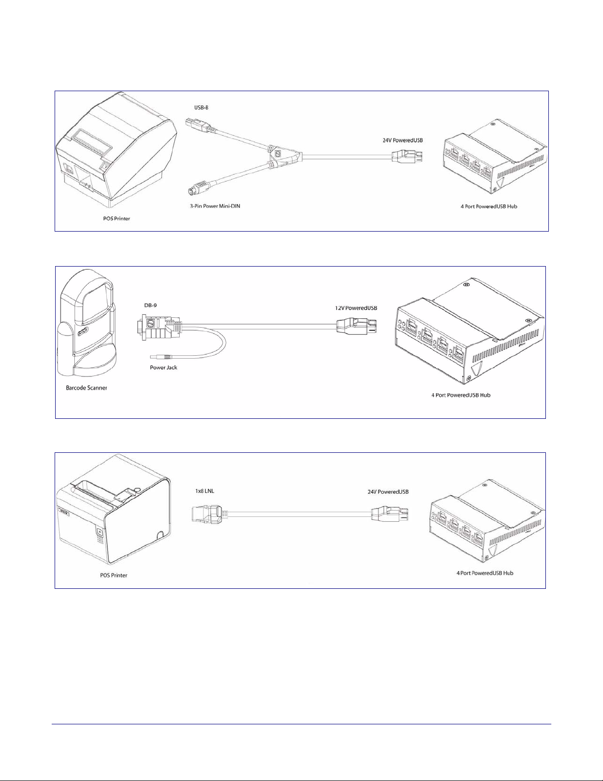
Figures 10 through 16 provide examples of peripheral cable combinations and connection options
for the SiP VoIP and PoE Speaker. The following table provides details about the CyberData
PoweredUSB Cables displayed in these figures.
Installing and Using the 4-Port PoweredUSB Hub
Connections
11
PoweredUSB cable sources
Custom cables of different lengths and colors can be purchased from CyberData as follows:
● Via email: [email protected]
● Via phone: Sales (831) 373-2601 Extension 334
Table 3. CyberData PoweredUSB Cables
Figure PoweredUSB Cable Description CyberData Part Number
Figure 2-11 12V to 2x4 010693C
Figure 2-12 12V to 12V Power Jack Contact CyberData
Figure 2-13 24V PoweredUSB to 3-Pin Power Mini-DIN 010631A
Figure 2-14 24V to “Y” Cable 3-Pin Power Mini-DIN to USB “B” 010714A
Figure 2-15 12V to “Y” Cable, RS232 and Power Jack 010763
Figure 2-16 24V to 1x8 010617A
Figure 2-17 24V to “Y” Cable, RS232 and Power Jack
Figure 2-11. Cable, +12V PoweredUSB to 2x4 PoweredUSB
Operations Guide 930103E CyberData Corporation
Page 15
Installing and Using the 4-Port PoweredUSB Hub
Figure 2-12. Cables; +12V PoweredUSB to +12V Power Jack and RS-232 to RS-232
Connections
12
Figure 2-13. Cables; +24V PoweredUSB to 3-Pin Mini-DIN and RS-232 to RS-232 or Parallel to Parallel
Operations Guide 930103E CyberData Corporation
Page 16
Installing and Using the 4-Port PoweredUSB Hub
Connections
Figure 2-14. “Y” Cable, +24V PoweredUSB to 3-Pin Power Mini-DIN and USB “B” Connectors
Figure 2-15. RS232 to USB Converter “Y” Cable +12V (PC Enumerates this device as an RS-232 COM port)
13
Figure 2-16. Cable, +24V PoweredUSB to 1x8 PoweredUSB
Operations Guide 930103E CyberData Corporation
Page 17
2.5 Operation
The SiP VoIP and PoE Speaker is a standard USB Hub that complies with the USB 2.0 specification,
and adds PoweredUSB ports. When connected to a Host, it is enumerated as a Generic USB Hub. This
Hub also meets the PoweredUSB .08g specification. For more information about this specification,
go to www.poweredusb.org.
Installing and Using the 4-Port PoweredUSB Hub
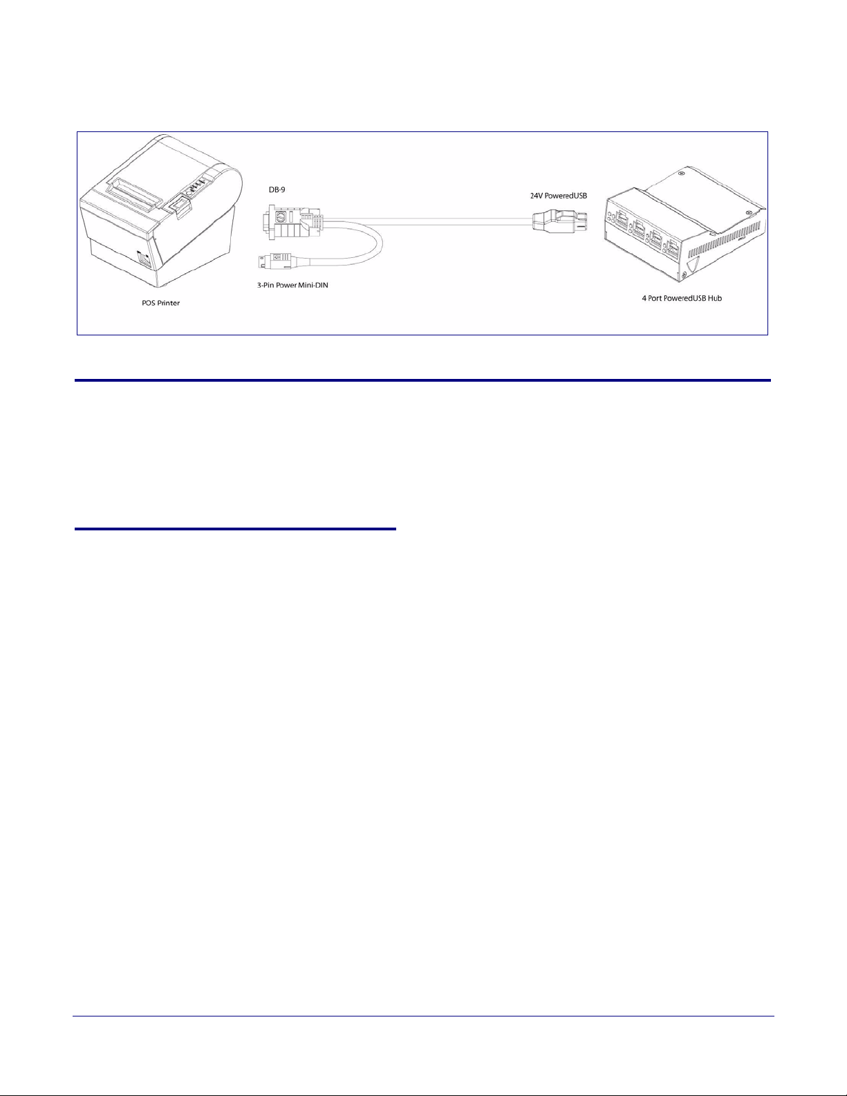
Figure 2-17. RS232 to USB Converter “Y” Cable +24V
Operation
14
2.5.1 POS Peripheral Caveat
According to the USB 2.0 specification, devices attached to a USB interface should enumerate from
the Hub’s USB Vbus, regardless of the PoweredUSB powered ports. Some POS devices do not
comply with this specification, and will not enumerate unless the upper sections of the PoweredUSB
ports are active.
When running on operating systems such as Windows XP with no devices attached (an empty Hub),
the operating system turns the Hub off. The operating system does not detect non-compliant
peripherals when they are hot-plugged into an empty Hub. Consequently PoweredUSB power is
not supplied to the peripheral. In this case, you can restore correct operation as follows.
1. Unplug the Host side connection for five seconds, and then plug it in again.
2. Be sure that at least one USB device is plugged in when the computer is booted, or leaves
standby mode.
3. Plug in a standard USB compliant device, such as a mouse or keyboard.
4. Disable the low-power, standby operation. With this configuration, power is always supplied to
the PoweredUSB ports regardless of the PC’s operational state. For more information, contact
CyberData as instructed in
Appendix C, "Troubleshooting/Technical Support".
Operations Guide 930103E CyberData Corporation
Page 18

2.6 Port Electrical Specifications
The SiP VoIP and PoE Speaker adheres to the USB 2.0 electrical specifications as follows:
2.6.1 Standard USB lower A supply
Each lower portion of the PoweredUSB port provides +5V @ 500mA. If more than 500mA are drawn
from a port, that port goes into USB over current, the +5 volts is turned off, and the condition is
reported to the host according to USB 2.0 specifications.
2.6.2 PoweredUSB supply
The listed maximum currents depend on the selected power supply. Both the +12V and +24V
PoweredUSB ports are protected with active over current circuits. If an over current condition
occurs, unplug the DC connection, remove the overcurrent condition, and re-cycle the DC
connection to the Hub by unplugging it, and then plugging it in again.
● +12V Ports (3) – 1.5A each
● +24V Port (1) – 2.3A
Installing and Using the 4-Port PoweredUSB Hub
Port Electrical Specifications
15
Operations Guide 930103E CyberData Corporation
Page 19

Appendix A: Regulatory and Safety Information
16
Regulatory standards
FCC Statement: This equipment has been tested and found to comply with the limits for a Class A
digital device, pursuant to Part 15 of the FCC Rules. These limits are designed to provide reasonable
protection against harmful interference when the equipment is operated in a commercial
environment. This equipment generates, uses, and can radiate radio frequency energy and, if not
installed and used in accordance with the instruction manual, may cause harmful interference to
radio communications. Operation of this equipment in a residential area is likely to cause harmful
interference in which case the user will be required to correct the interference at his own expense.
Safety standards ● UL60950-1; Information Technology Equipment
● CSA C22.2 No. 60950-01, Information Technology Equipment
● EN60950-1, Information Technology Equipment
● IEC60950-1, Information Technology Equipment
EMC For the USA and Canada, this device complies with:
● Title 47 of the CFR, Part 15, Subpart B, Section 15.107(b)
● Title 47 of the CFR, Part 15, Subpart B, Section 15.109 (b)
● ICES-003
CE Declaration of Conformity
This device complies with:
● Directive 89/336/EEC
● EN55022 Class A 1998
• EN61000-3-2: 2000
• EN61000-3-3: 1995
● EN55024: 1998
• EN61000-4-2: 1995
• EN 61000-4-3:1996
• EN 61000-4-4: 1995
• EN 61000-4-5: 1995
• EN 61000-4-6: 1996
• EN 61000-4-8: 1993
• EN 61000-4-11: 1995
Operations Guide 930103E CyberData Corporation
Page 20

Appendix B: Setting up the Hub on Windows XP
For connecting the SiP VoIP and PoE Speaker to a PC running the Windows XP operating system,
keep in mind:
1. Microsoft XP Service Pack 1 or higher must be installed.
2. When connecting the Hub for the first time, it is important to perform the enumeration
correctly. A Microsoft XP Service Pack issue does not enumerate and recognize a Hub when no
devices are attached to it. To correctly enumerate the SiP VoIP and PoE Speaker, attach a
peripheral whose drivers are included in Windows XP, such as a USB mouse, prior to
enumerating the Hub. To accomplish this:
a. Connect a USB mouse to one of the lower, standard USB, Hub ports.
b. Connect the power cord to the Hub.
c. With the PC powered up, connect the host control cable from the Hub to a USB port on the
PC. Doing so displays the Found new hardware dialog, indicating that the PC is searching for
drivers for the Hub.
d. When the PC completes the driver search, it displays the Found new hardware dialog, in
search of a driver for the mouse. If required, click Next in all screens of the wizard to
complete the driver selection for the mouse.
17
At this point, you should be able to plug in and install a USB device provided you have also
installed its drivers, or have them available for installation.
Operations Guide 930103E CyberData Corporation
Page 21

Appendix C: Troubleshooting/Technical Support
C.1 Frequently Asked Questions (FAQ)
Go to the following URL to see CyberData’s list of frequently asked questions:
http://www.cyberdata.net/support/pusb/4portpusb.html
C.2 Documentation
The documentation for this product is released in an English language version only. You can
download PDF copies of CyberData product documentation at:
18
www.CyberData.net—>Support—>Drivers, Utilities & Manuals—>PoweredUSB, 4 Port Hub
C.3 Contact Information
Contact CyberData Corporation
2555 Garden Road
Monterey, CA 93940
USA
www.CyberData.net
Phone: 800-CYBERDATA (800-292-3732)
Fax: 831-373-4193
Sales Sales 831-373-2601 Extension 334
Technical Support
Returned Materials Authorization
Phone: 831-373-2601 Extension 333
Email: [email protected]
To return the product, contact the CyberData Returned Materials Authorization (RMA) department
at:
Phone: 831-373-2601, Extension 136
Email: [email protected]
When returning a product to CyberData, an approved CyberData RMA number must be printed on
the outside of the original shipping package. No product will be accepted for return without an
approved RMA number. Send the product, in its original package, to the following address:
Operations Guide 930103E CyberData Corporation
Page 22

CyberData Corporation
2555 Garden Road
Monterey, CA 93940
Attention: RMA "your RMA number"
C.4 Warranty
CyberData warrants its product against defects in material or workmanship for a period of two
years from the date of purchase. Should the product fail within the warranty period, CyberData will
repair or replace the product free of charge. This warranty includes all parts and labor.
If the product is out-of-warranty and fails, a flat rate repair charge of one half the product purchase
price will be assessed. Repair costs for products that are in warranty, but damaged by improper
modifications or abuse, will be charged at the out-of-warranty rate. Products returned to CyberData,
both in and out-of-warranty, are shipped to CyberData at the expense of the customer. Charges for
shipping repaired products back to the customer will be paid by CyberData.
Warranty
19
Operations Guide 930103E CyberData Corporation
Page 23

Index
20
A
accessory kit 5, 8
active over current circuits. 15
C
cable routing 10
cable strain relief clamp 5
cables for connecting peripherals 11
CE conformity 16
CFR 16
color keys for ports 9
compatibility matrix 6
components list 5
connector color keys 9
CyberData
license with IBM 2
CyberData contact information, corporate, sales, tech
support, service 18
D
H
high-current power supply 7
host connector 5, 8
I
IBM 2
ICES 16
Information Technology Equipment 16
installation 6
L
license 2
M
Microsoft XP Service Pack 1 17
DC input jacks 7
Dell printer power supply 7
E
EMC 16
enumeration 14, 17
Epson PS180 brick 7
F
FCC 16
features 1
G
generic USB hub 14
O
over current protection 1
P
peripheral connections 11
power supply connections 7
PoweredUSB .08g specification 14
PoweredUSB connections 8
product
accessory kit 5, 8
CE conformity 16
compatibility matrix 6
components list 5
enumerating 14
enumeration 17
features 1
installation 6
regulatory standards 16
resell/release conditions 2
product compatibility 6
CyberData Corporation 930103E Operations Guide
Page 24

R
regulatory standards 16
resetting the IP address to the default 18
RMA returned materials authorization 18
S
short circuit protection 1
T
technical support, contact information 18
U
21
USB
2.0 specification 14
over current 15
W
warranty 1, 19
Windows XP 14, 17
Operations Guide 930103E CyberData Corporation
 Loading...