

Page 1
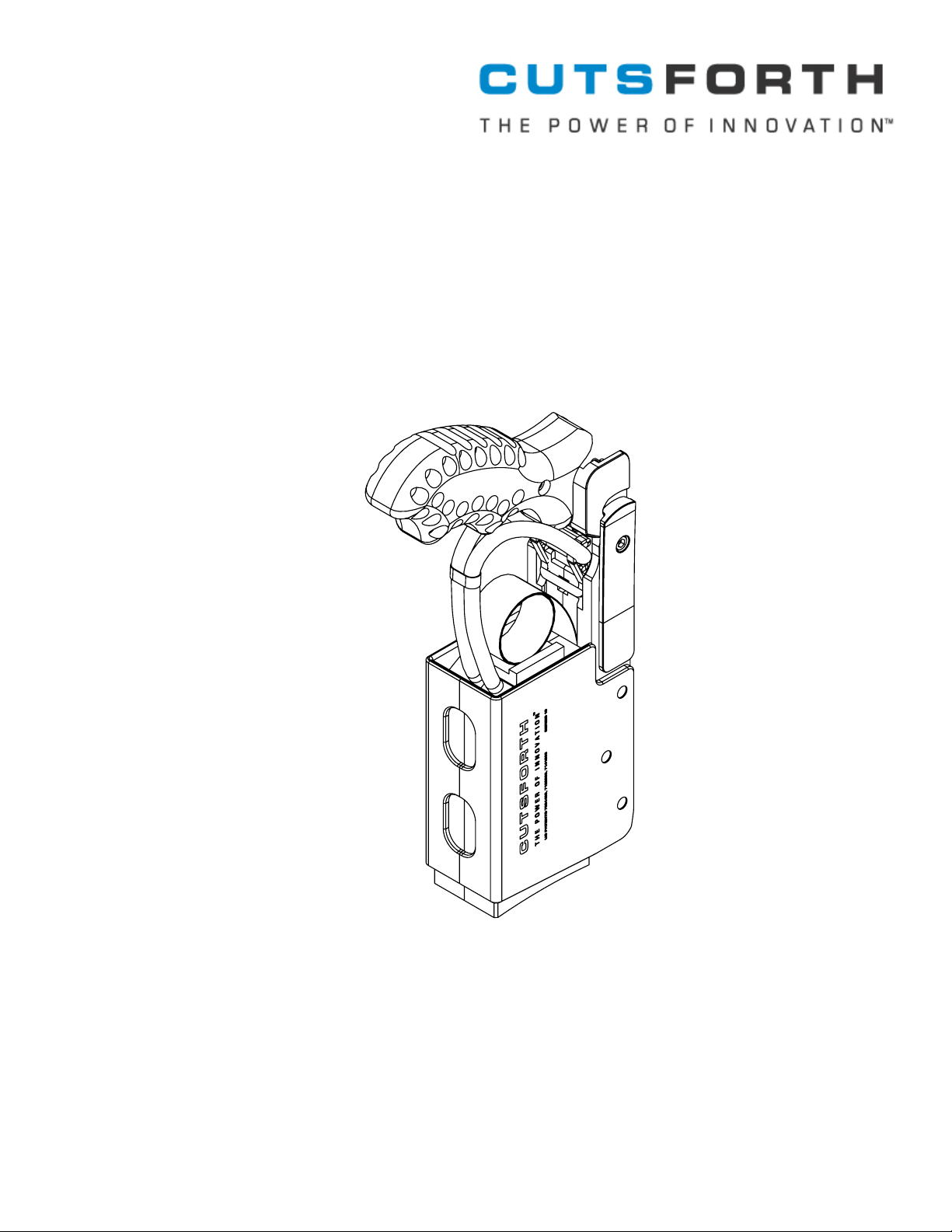
Cutsforth Brush Holder System
Operation Manual
Cutsforth 7854 12th Avenue South Bloomington, MN 55425 www.cutsforth.com 800.290.6458 fax: 800.398.6530
Part No. CED-1008A
Page 2

Page 3

Safety Precautions
Cutsforth Brush Holder Operation Manual
Warning
Introduction
High voltage and rotating parts can cause serious or fatal injury.
Installation, operation, and maintenance of this product must
only be performed by qualied personnel, in accordance with
all applicable manufacturer, OSHA, and local plant safety
regulations and guidelines.
When working with the Cutsforth Brush Holder, it is important to
observe safety precautions. Among the many considerations:
Avoid contact with energized circuits.•
Avoid contact with rotating parts.•
Never install any component that appears to not be •
functioning in a normal manner.
Always ensure proper installation of the brush holder •
assembly.
This manual covers:
introducing Cutsforth Brush Holder components.•
knowing when to change a brush.•
removing the Cutsforth Brush Holder.•
inspecting the holder.•
changing the spring and brush.•
remounting the holder.•
removing and installing the mount.•
Note
This manual does not claim to cover all details or variations in equipment or to
provide for every possible contingency that could be faced during installation,
operation, and maintenance. Should additional information be required, please
contact Cutsforth, Inc.
3
Page 4
Cutsforth Brush Holder Operation Manual
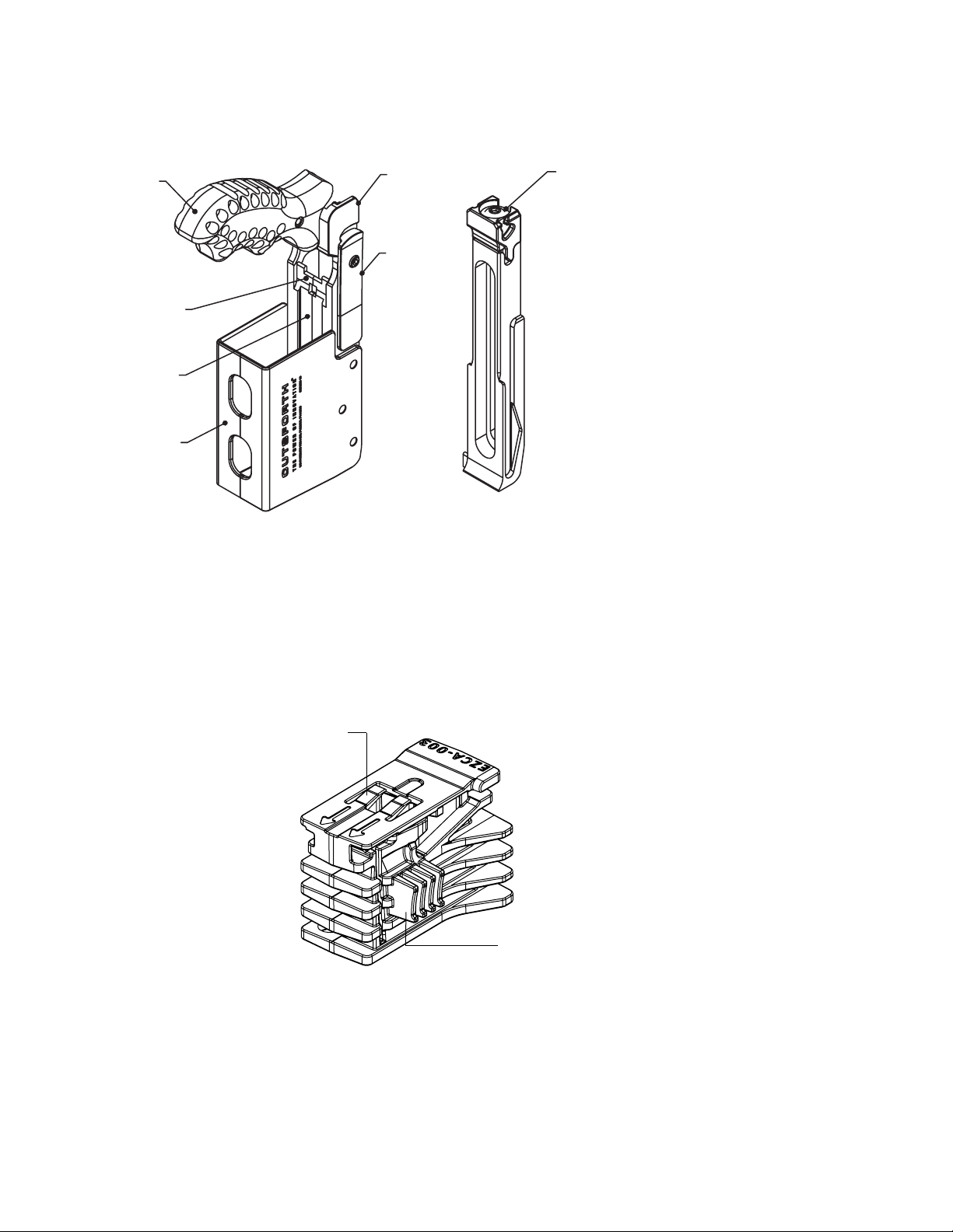
Introducing Cutsforth Brush Holder Components
Handle
(Grip)
Terminal Mount
Rib
Lower Beam
Brush Box
Upper Beam
Catch
Arm
MountHolder
Caution
Do not adjust the 1032 screw on the top
of the mount. This
fastener is set at the
factory and does not
need to be changed.
Improper adjustment
of this fastener on
older models disables
the over center
locking mechanism.
The latest models
cannot be improperly
adjusted.
Brush Spring Release Fingers
Release Tab
Brush Key
4
Page 5
Knowing When to Change a Brush
Cutsforth Brush Holder Operation Manual
Caution
Many factors inuence brush wear:
spring pressure•
ring condition•
current density•
atmospheric conditions•
presence of contaminants•
holder condition•
brush grade•
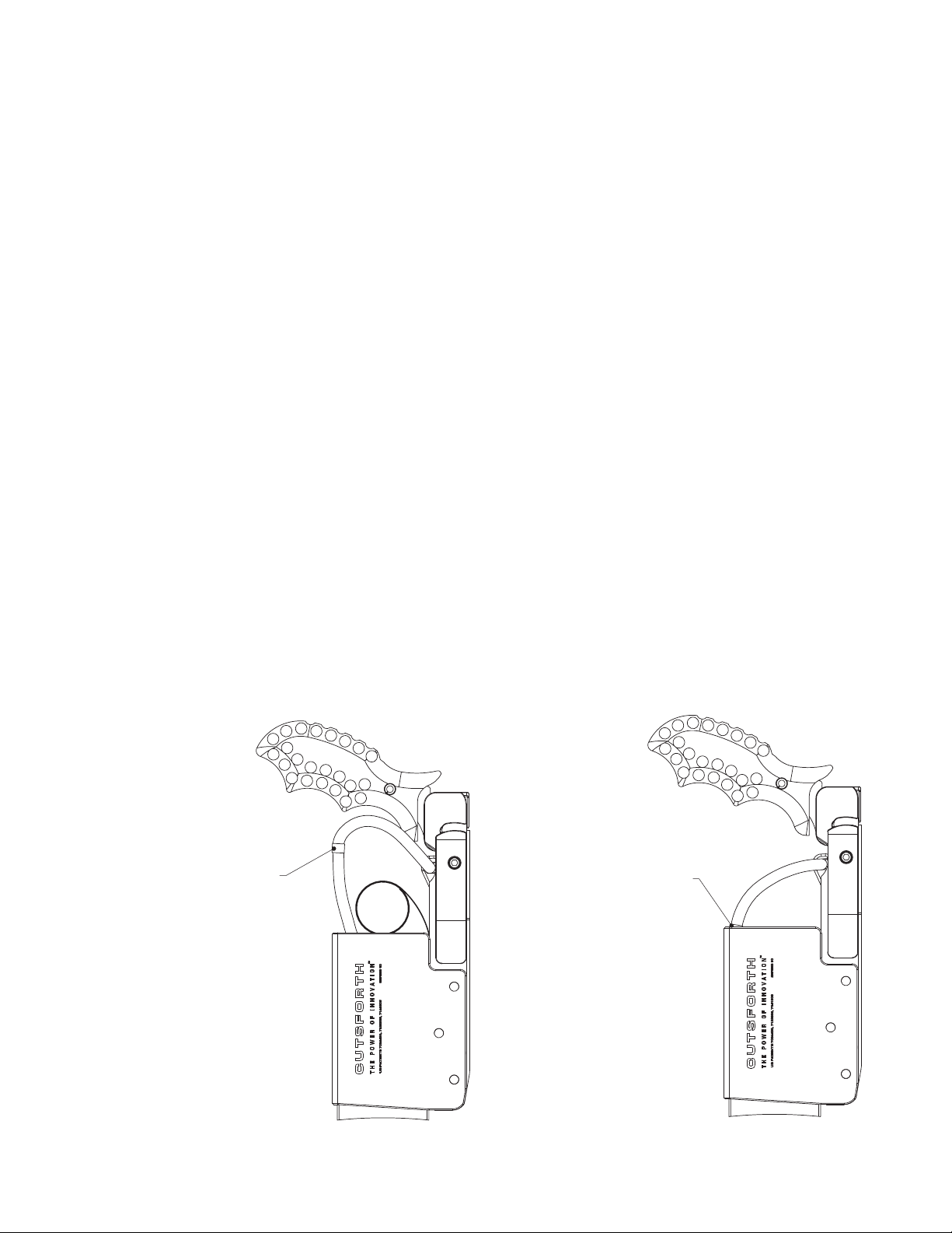
Replace brushes before they become too short. Frequently inspect the brushes to determine if they need to be replaced by checking the wear indicator.
Only replace a small percentage (10%-20%) of brushes at a time if brushes are being
changed “live.” Once installed, allow the new brushes to sufciently wear (seat in at least
50%) to the ring’s prole before replacing more.
Accepted practice is to replace only a small portion of brushes at one time
(this number varies depending on the unit). New brushes only contact the
ring across a very small area. Ensuring that the brush faces are seated at
least 50% before replacing more brushes is typical.
Wear
indicator
on a new
brush
Wear indicator
on a brush that
needs to be
replaced
5
Page 6
Cutsforth Brush Holder Operation Manual
Removing the Holder
Warning
Changing brushes on a unit in operation exposes personnel to dangerous
voltages. Use approved safety gloves while removing the holder.
Caution
Removing multiple holders while the unit is in service can be very
dangerous. The current that was owing through a removed brush is
picked up by the remaining brushes. Removing too many holders at once
can force excessive current through the remaining brushes resulting in
catastrophic failure.
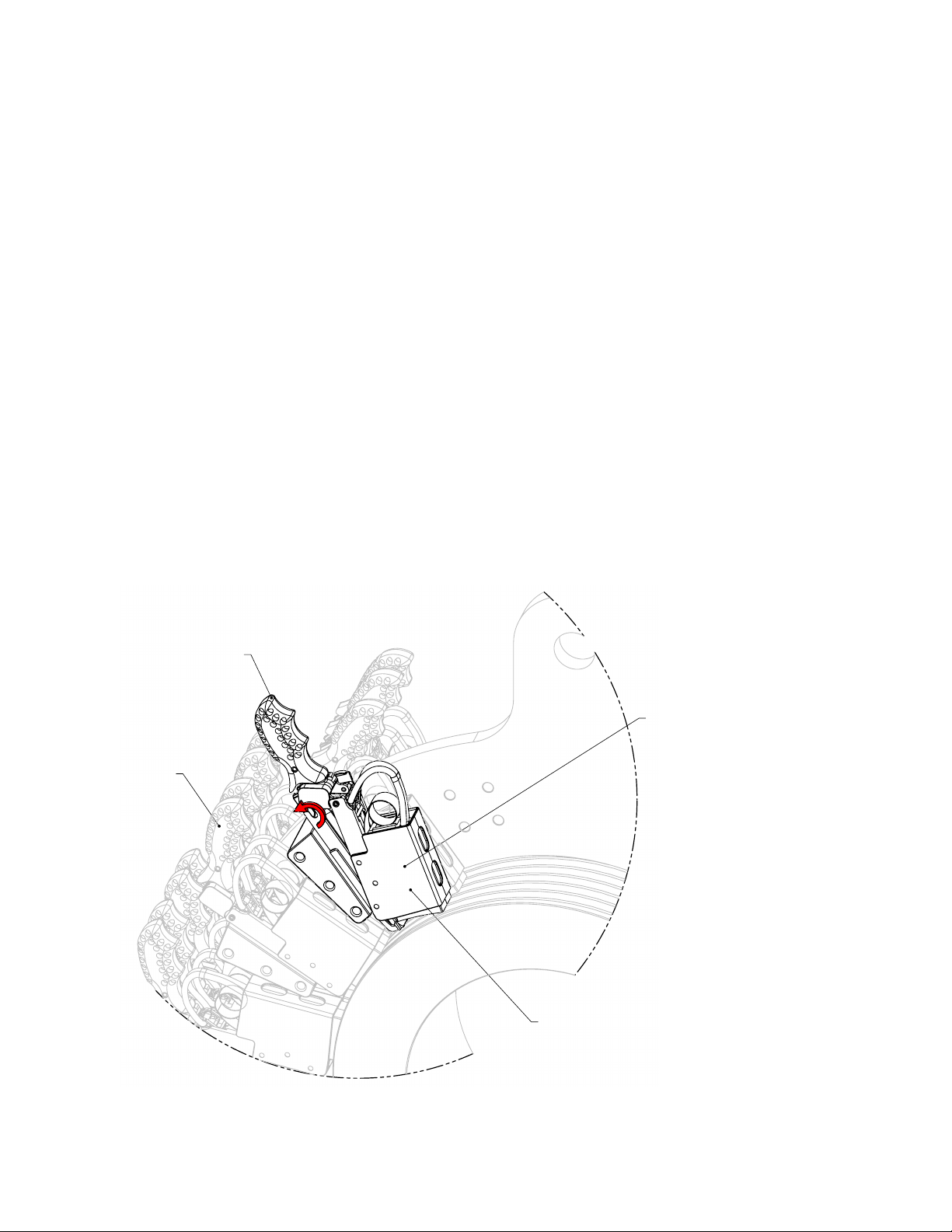
The unlocking motion of the Cutsforth Brush Holder automatically disengages the
terminal so the holder and the brush can safely and easily be removed with one hand.
To remove the holder
While maintaining control of the holder, lift the handle and rotate it to its retracted 1.
position.
Locked or
Engaged
Position
Handle
Retracted
Position
Brush Holder
6
Page 7
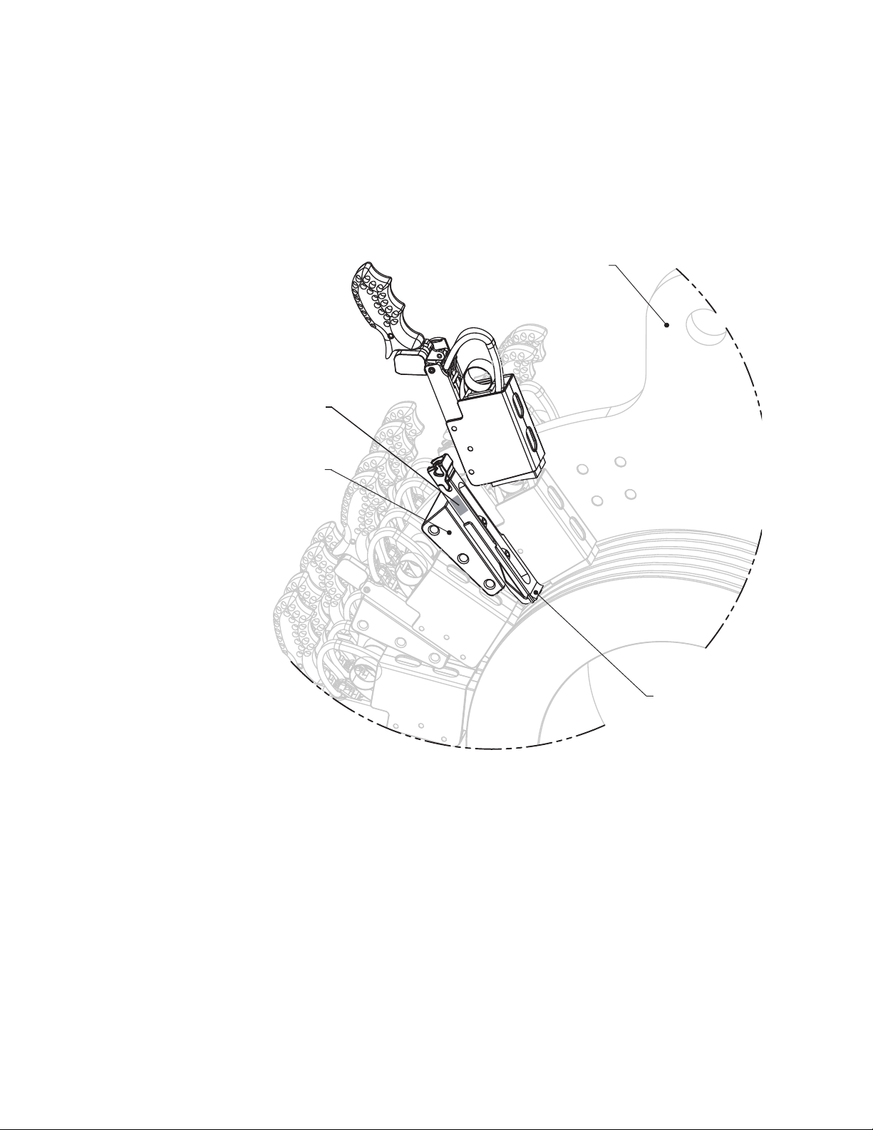
Pull the holder free and away from its mount. Make sure the terminal connection area 2.
on the mount is not excessively worn or pitted.
Terminal
Connection Area
Adapter
Cutsforth Brush Holder Operation Manual
Yoke Bus
.
Mount
7
Page 8

Cutsforth Brush Holder Operation Manual
Online Inspections
It is normally not necessary to remove the brush holder for inspection prior to changing a
worn brush. Watch for the following indicators of problems:
Arching from the trailing edge of the brush (visual).•
Discolored brush leads (visual).•
Brush photographing (imaging) on the ring (visible with strobe).•
The frequency of inspections is unit specic generally ranging from every day to once per
week.
Inspecting the Holder Ofine
To ensure that the holder is in proper working condition, make the following inspections:
Inspect the holder for any signs of wear or damage as well as any excessive build up •
of dirt or foreign material.
Check for any cracking or breakage of components or welds.•
Ensure the brush catch is holding the brush in the brush box when the holder is disen-•
gaged from its mount.
Conrm the “snap in” pressure when installing or removing the holder is relatively •
equal to the other holders.
After the brush has been removed, inspect the sides of the brush for any signs of re-•
strictions such as scrapes or drag marks.
Inspect the inside of the brush box for obstructions such as box deformity, burrs, or •
carbon deposits. Clean the box using denatured alcohol. Remove carbon deposits using a plastic or wood object—avoid using sharp objects or abrasive cleaners as these
could damage the interior of the brush box.
8
Page 9

Cutsforth Brush Holder Operation Manual
Replacing the Spring and Brush
After the holder has been removed from the rigging, the spring and brush can be safely
removed with the use of the Brush Key.
To replace the spring and brush
1. Pull the brush terminal free from the terminal mount rib prior to using
the Brush Key.
Brush Terminal
9
Page 10
Cutsforth Brush Holder Operation Manual
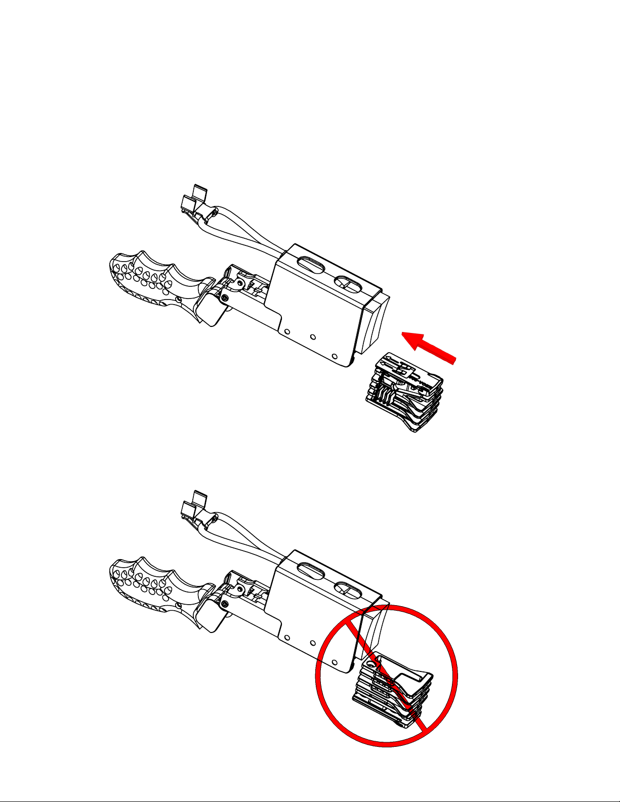
2.
Orient the Brush Key to the correct position in reference to the brush holder (see
illustrations A and B). Slide the Brush Key into the lower beam of the brush holder
(see illustration C). Press down onto a at surface until the Brush Key is fully
engaged (see illustrations D.)
A.
Insert the Brush Key with this Orientation
B.
Do NOT Insert the Brush Key with this Orientation
10
Page 11
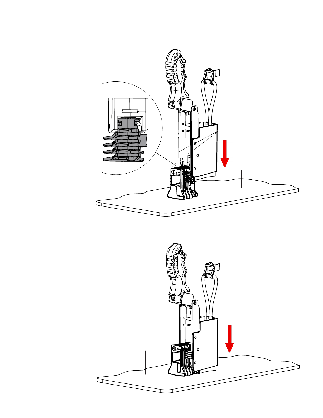
C.
Cutsforth Brush Holder Operation Manual
Slide the Brush Key into the Lower Beam of the brush holder.
Lower Beam
.
.
Flat Surface
D.
.
Press down onto a Flat Surface until the Brush Key snaps into the brush holder.
Flat Surface
.
11
Page 12
Cutsforth Brush Holder Operation Manual
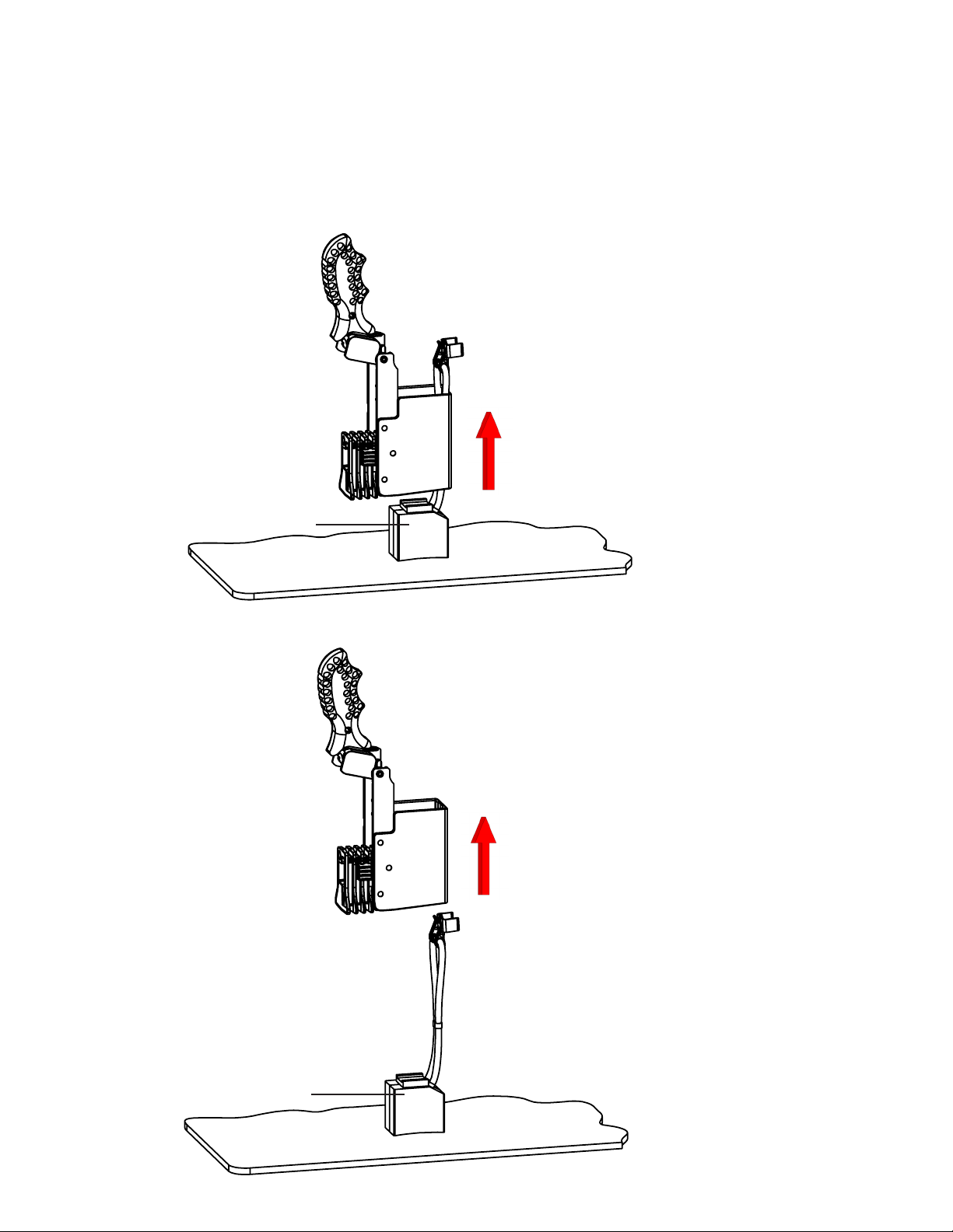
3.
When the Brush Key is fully engaged into the brush holder the old brush will
become free to slide out when holder is pulled away (see illustrations A
and B).
A.
Old Brush
.
12
B.
Old Brush
.
Page 13
Cutsforth Brush Holder Operation Manual
4.
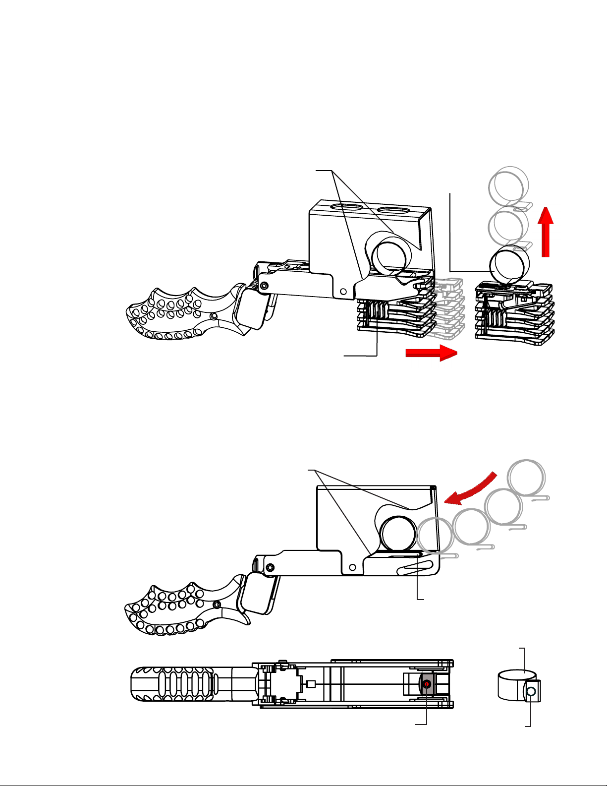
To remove the old brush spring, press in on the release tab of the Brush Key and pull
it out of the brush holder. The brush spring release ngers will grab the brush spring
as the Brush Key is pulled out of the brush holder. Remove the old brush spring and
discard. (See illustration below)
Cutaway
Old Brush
Spring
.
.
.
.
Release Tab
5. Insert the new brush spring onto the spring rib and push until the spring
hole snaps onto the spring pin. (See illustration below)
Cut Away
.
.
.
Spring Rib
Spring
.
.
.
Spring Pin
Spring Hole
13
Page 14
Cutsforth Brush Holder Operation Manual
6.
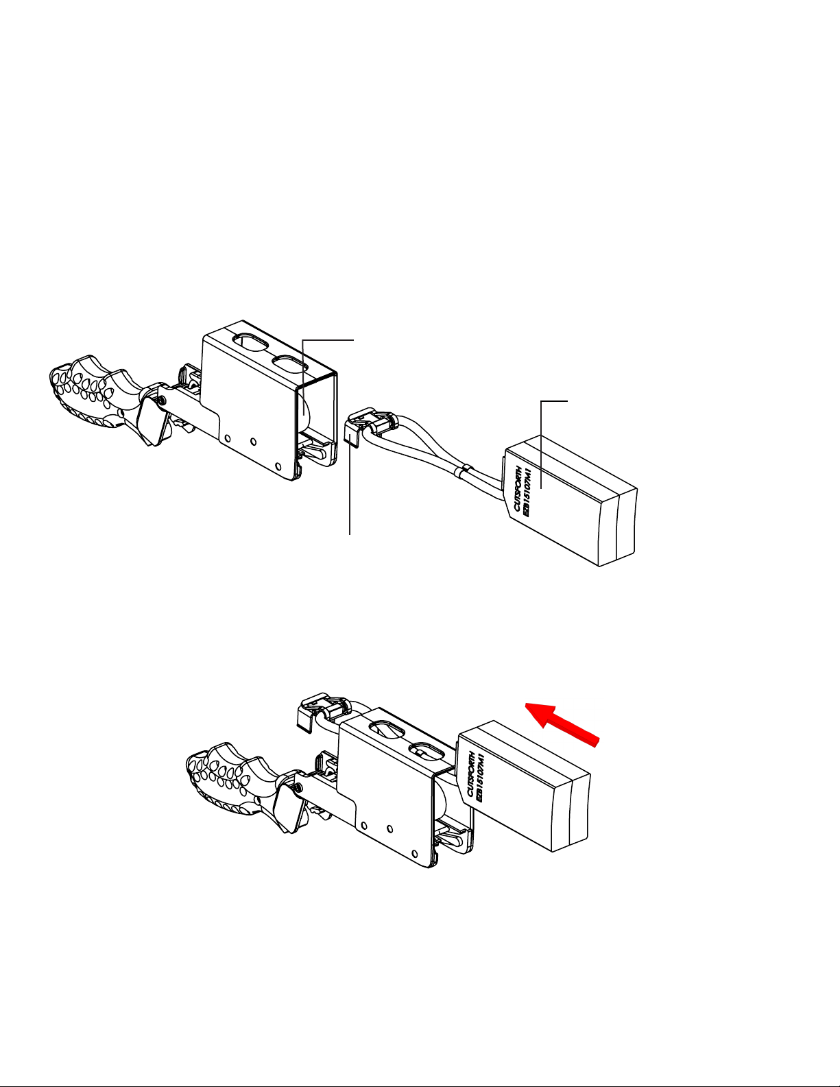
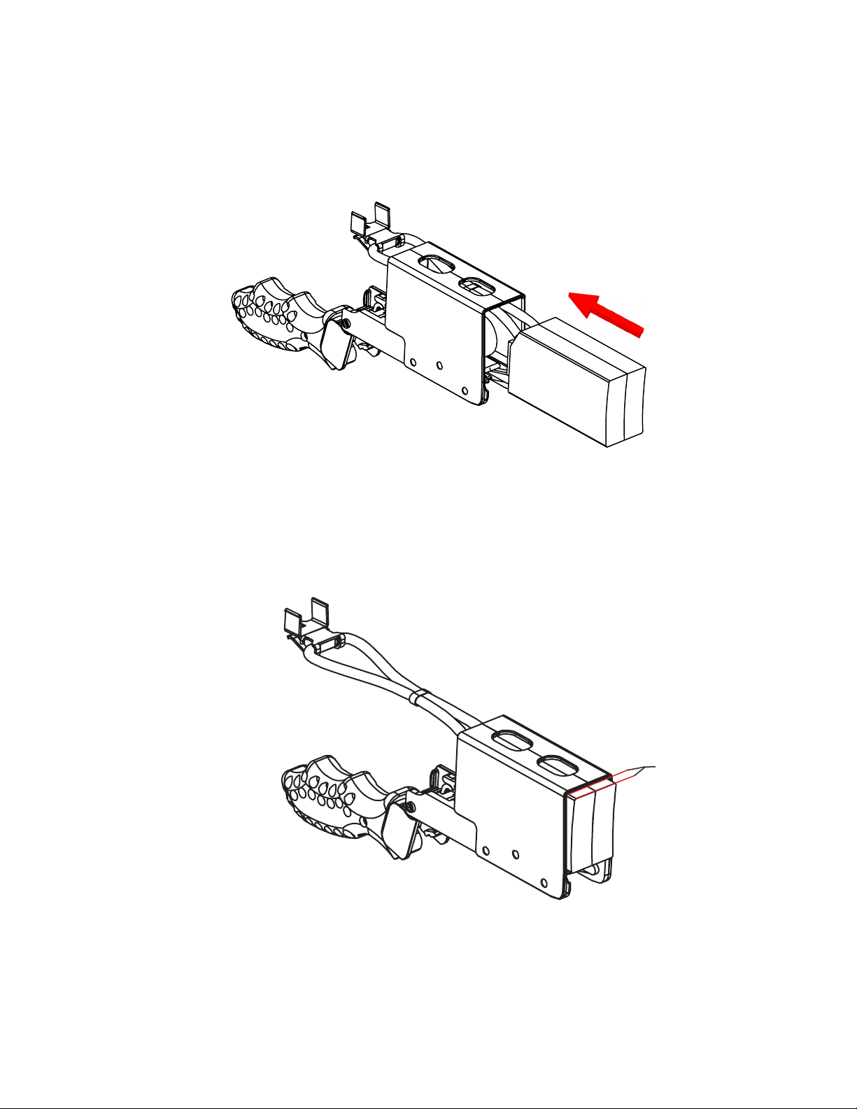
To insert the new brush, start by orienting the brush with the terminal ears
pointing down (see illustration A). Then, insert the brush into the holder until
the terminal ears pass the brush spring (see illustration B). Next, rotate the
brush so the terminal ears are pointing up (see illustration C). Then, insert
the brush the rest of the way into the holder until approximately 1/8” is sticking out of the brush box (see illustration D).
A.
Brush Spring
.
New Brush
.
.
B.
Terminal Ears Pointing Down
Terminal Clear of Brush Spring
14
Page 15
C.
Cutsforth Brush Holder Operation Manual
Terminal Ears Pointing Up
D.
Approximately
1/8”
New Brush Fully Engaged
15
Page 16
Cutsforth Brush Holder Operation Manual
7.
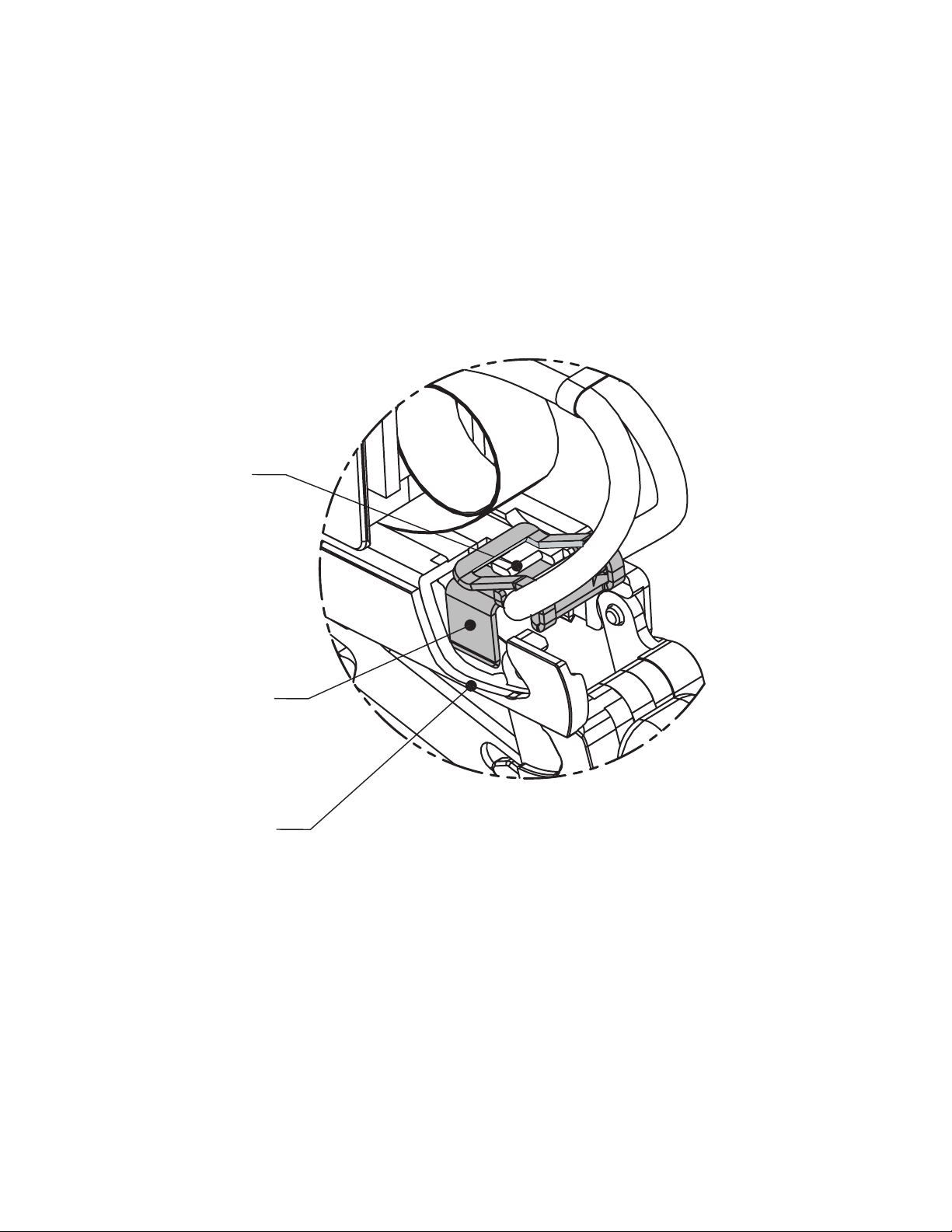
Insert the brush terminal onto the terminal mount rib.
Terminal
Mount Rib
Brush Terminal
Cutaway
16
Page 17
Cutsforth Brush Holder Operation Manual
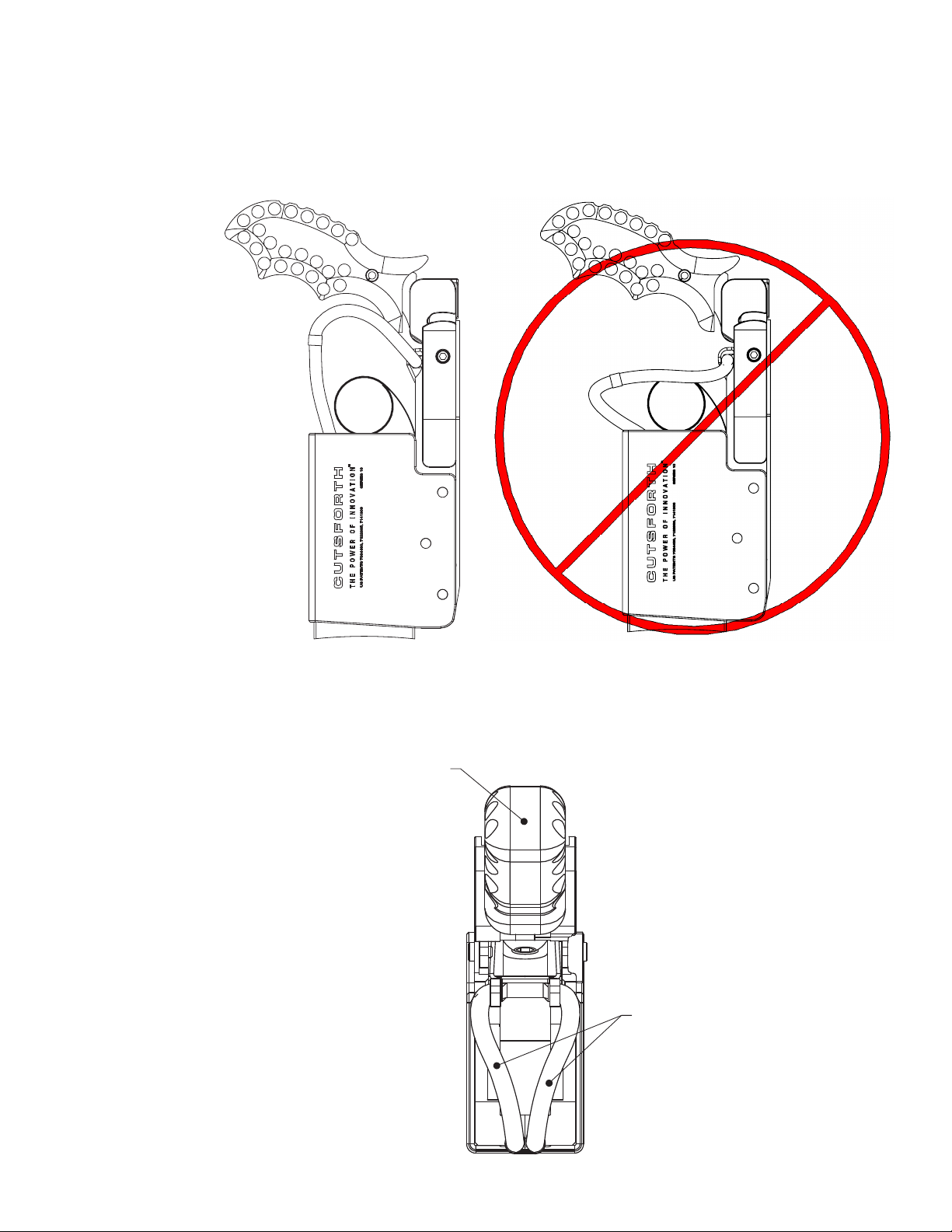
8.
To prevent brush binding, lead damage, and interference with the handle, position
the brush shunts as shown in the following illustrations.
Brush Shunts Formed
Straight Up So They Will
Not Catch on the Box
Handle
Caution: Do not position the brush shunts
as shown or the shunts will restrict free
movement of the brush (hang up).
Brush Shunts
Spread as Shown
17
Page 18
Cutsforth Brush Holder Operation Manual
Returning the Holder to Service
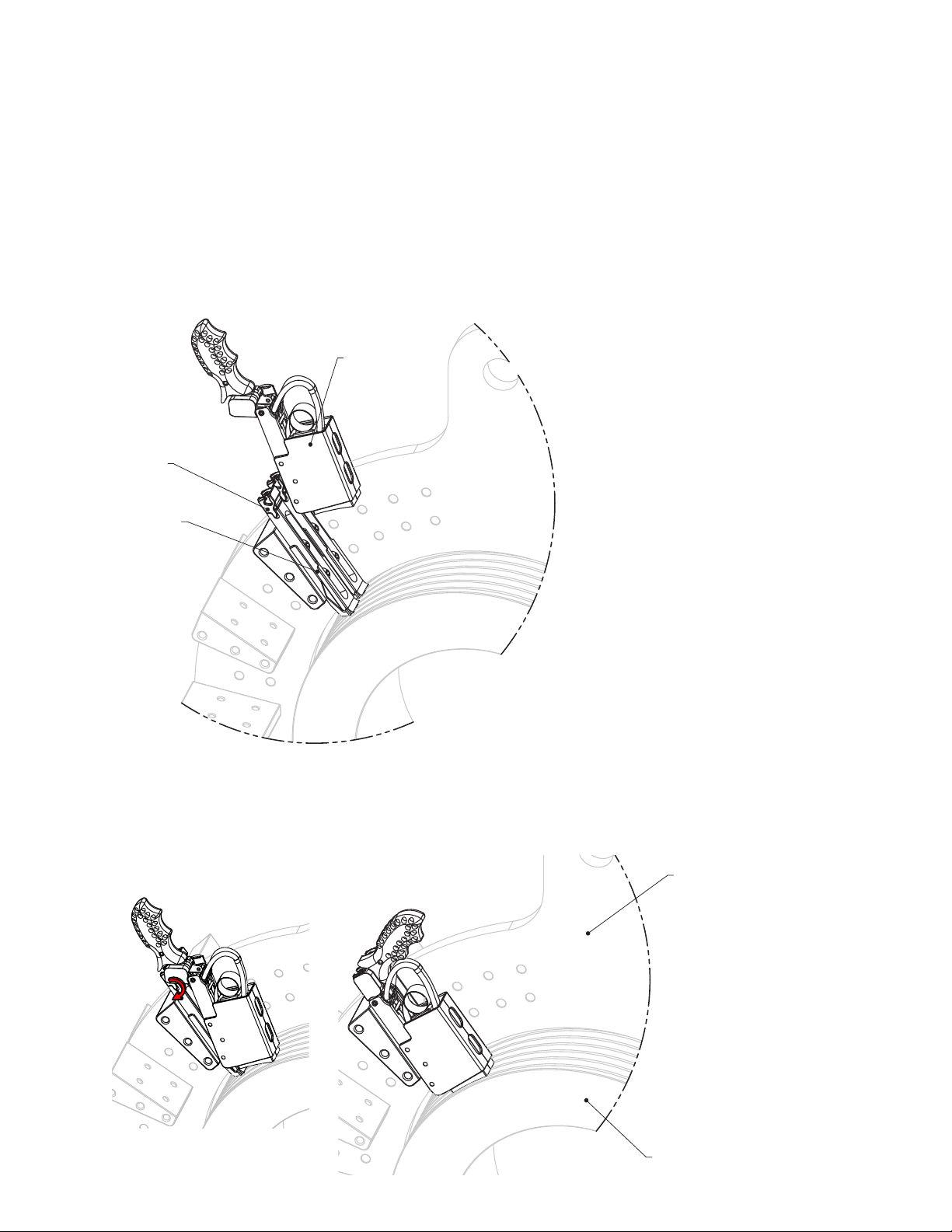
After a new spring and brush are installed, the holder is ready to be returned to service.
To remount the holder
Align the holder with the grooves on the sides of the mount and slide the holder 1.
into the mount.
Holder
Mount
Grooves
Rotate and lock the handle into place while applying light pressure toward the ring. 2.
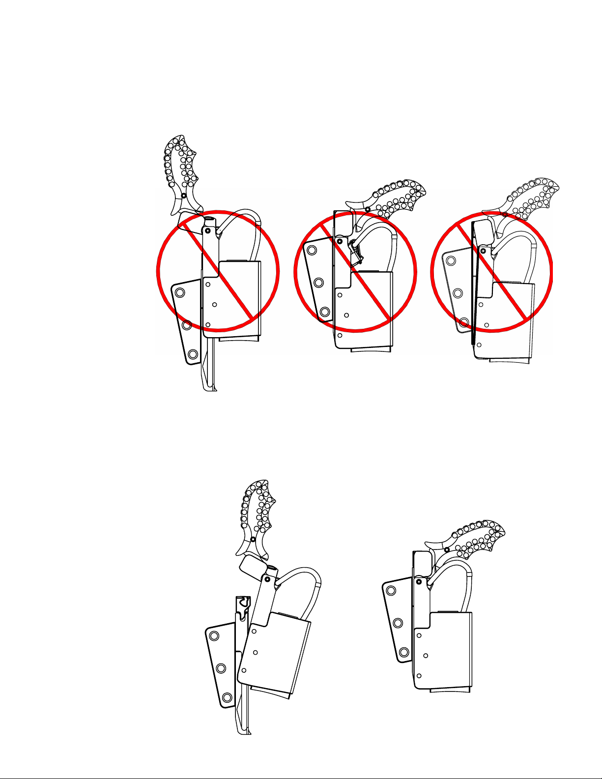
Once the holder is fully engaged into position, check the brush holder to verify that
it is installed correctly as described on page 19 and that the brush leads are properly
formed as described on page 17.
Yoke
Bus
18
Ring
Page 19
A.
Incorrectly Mounting the Brush Holder
Cutsforth Brush Holder Operation Manual
I - Misaligned
Insertion
II - Disengaged
Terminal
III - Brush Holder not
Fully Engaged.
B.
Correctly Mounting the Brush Holder
I - Correctly Aligned
Insertion
II - Properly Engaged
Terminal and Holder.
19
Page 20
Cutsforth Brush Holder Operation Manual
Removing and Installing the Holder Mounts
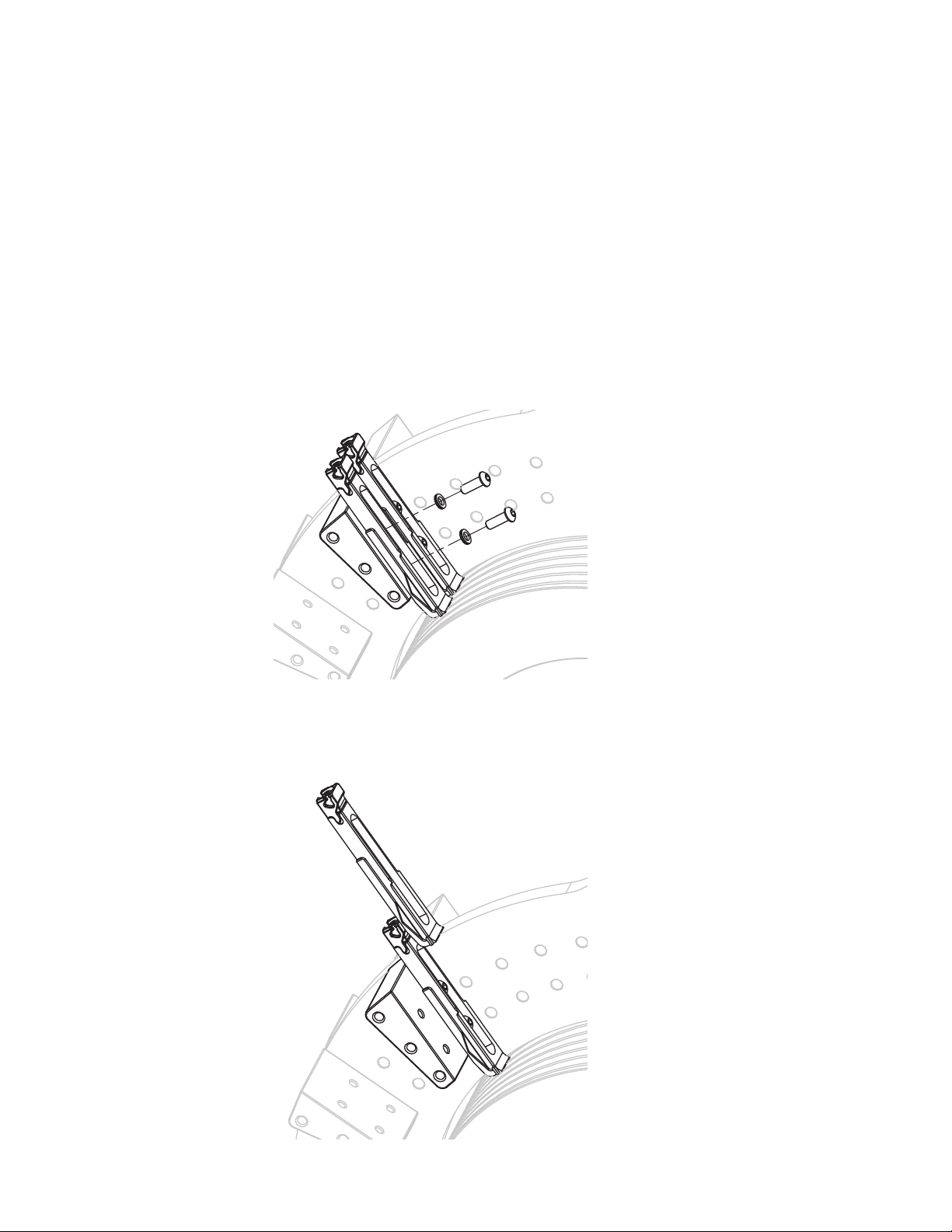
When it is necessary to reinstall the mounts, the following procedures should be followed.
Warning:
To remove the holder mounts
Before working on the mounts, de-energize and lock-out all power sources to
the generator, exciter, and accessory devices. Electric shock and death may
occur.
Using a 5/32-inch allen wrench, remove the 1/4-28 button head cap screws and 1.
NL6 Nordlock washers.
20
Remove the holder mount.2.
Page 21
To install the holder mounts
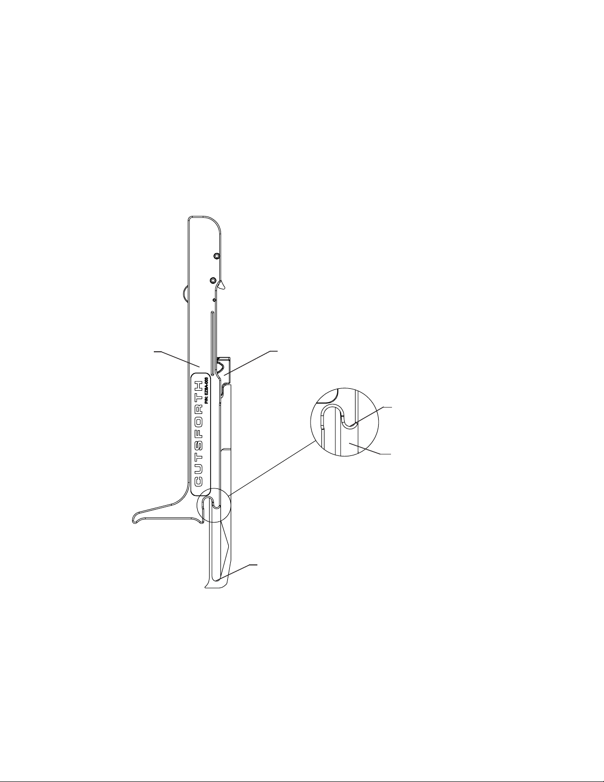
Slide the height setter onto the holder mount until the guide boss is bottomed out in 1.
the guide slot.
Cutsforth Brush Holder Operation Manual
Height Setter
Holder Mount
Guide Boss
Guide Slot
Bottom of Slot
21
Page 22
Cutsforth Brush Holder Operation Manual
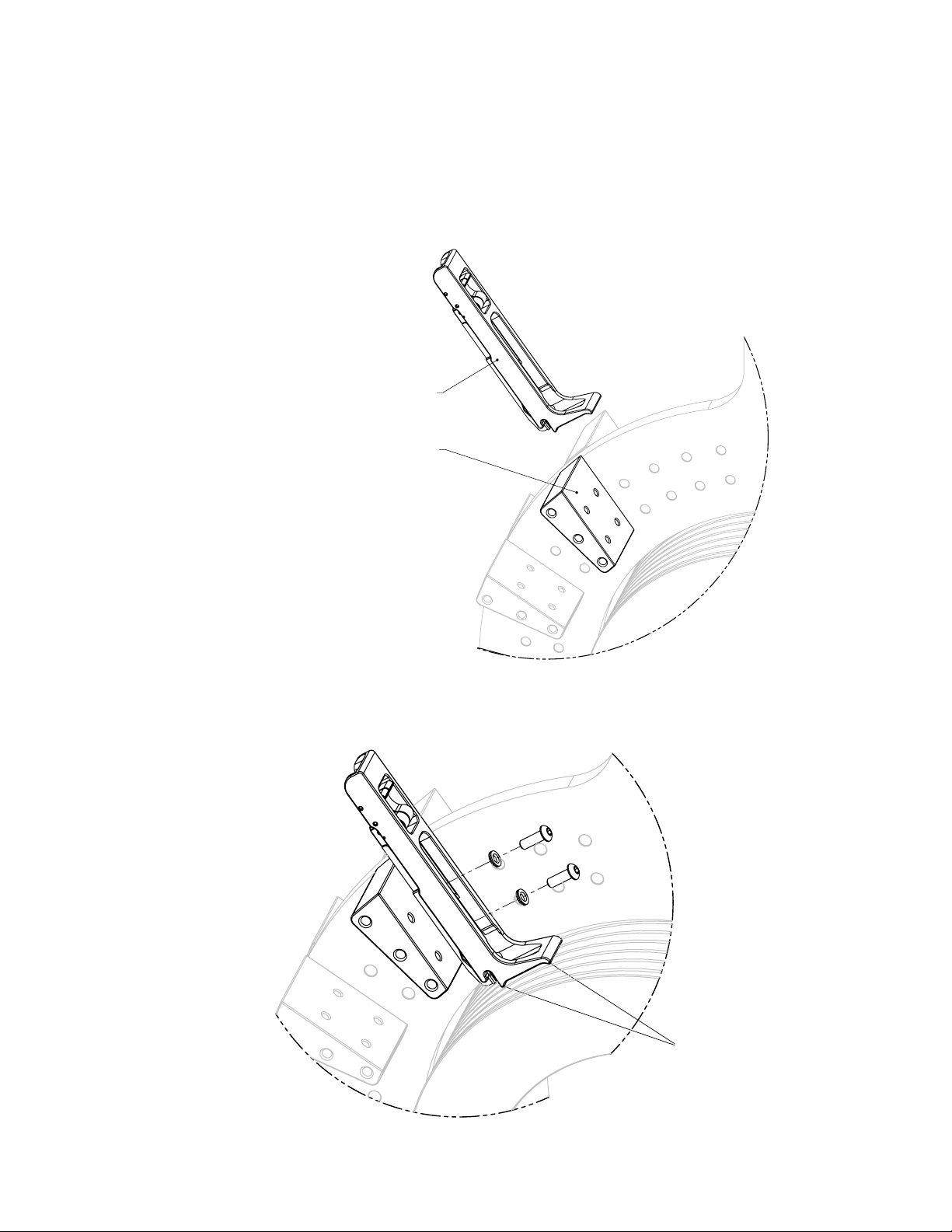
Making sure the mount is on the correct side of the adapter, place the holder mount 2.
against one of the adapters on the yoke buss, and position so that the height setter
is resting against the ring so that both ribs are contacting the ring. The adapter
may need to be properly adjusted. To maximize ring coverage, use the alternate
mounting positions on the adapters as needed.
Height Setter with
Mount
Mount Side of
Adapter
Using a 5/32-inch allen wrench, fasten the 1/4-28 button head cap screws and NL6 3.
Nordlock washers to 130 inch-pounds of torque.
Ribs
22
Page 23
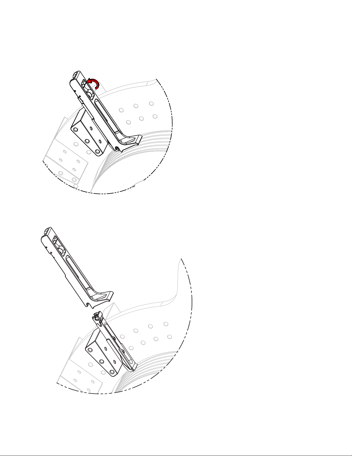
Pull the trigger back to the disengaged position and remove the height setter from 4.
the holder mount.
Cutsforth Brush Holder Operation Manual
23
 Loading...