

Pub 50255
Instructions for Installing PSS160E/C, 160 Watt,
24V DC Power Supply
!
WARNING
!
AVERTISSEMENT
Hazard of Burn or
Electrical Shock
Risque de Brulure ou
de Choc Electrique
TO AVOID SHOCK
HAZARD, DISCONNECT ALL
POWER BEFORE ANY
FUNCTIONS ARE
PERFORMED ON THIS
EQUIPMENT.
POUR EVITER TOUT
CHOC ELECTRIQUE,
COUPLER
L’ A L I MENTATION DE
CET EQUIPEMENT
AVANT D’Y
EFFECTUER DES
TRAVAUX .
Installation
The PSS160E/C Power Supply can be DIN rail or panel
mounted. The unit is designed to reach a crowbar current
and safely shut itself down when a secondary side short
circuit is encountered. The unit will recover automatically
when the short circuit is removed. For DIN rail mounting,
use the Accessory Catalog No. PSSDIN.
NOTE: WHEN WIRING THE SYSTEM, INSURE ALL
POWER IS REMOVED BEFORE BEGINNING THE
INSTALLATION.
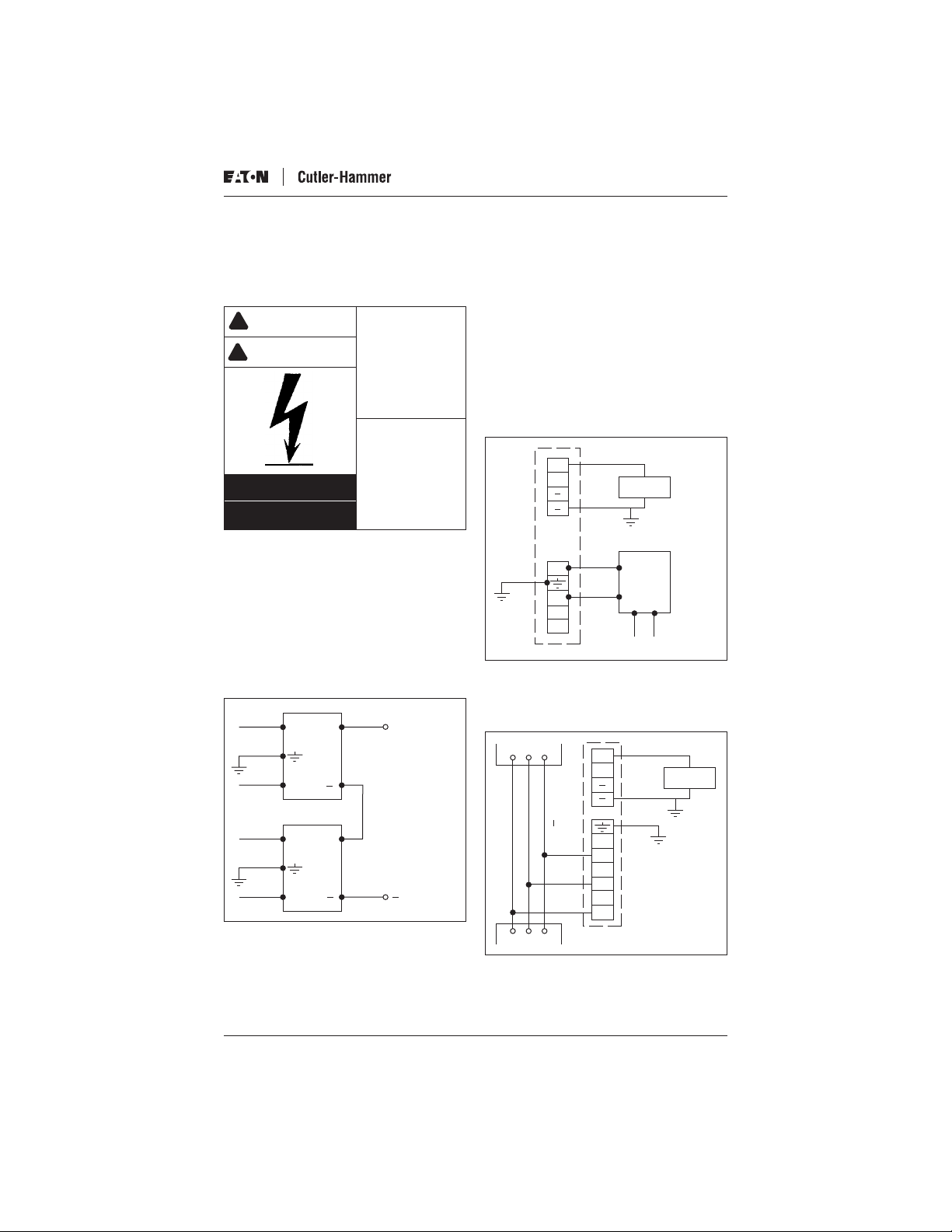
For 48V DC operations, the units can be operated in series
as shown in Figure 1.
L
+ +
48V DC
OUT
6.5 Amps
N
Input Wiring Requirements
115V AC or 230V AC Input
The PSS160E is a single-phase input unit. It has a selectable input voltage of 115V AC or 230V AC. To select 115V
AC input you must install the jumper cable (included with
unit) between the 2 VS terminals. To select 230V AC operation, leave jumper off.
To wire, connect the (L) terminal to line voltage, the (N)
terminal to neutral and the center terminal to ground. See
Figure 2.
+
+
L
N
VS
Load
CPT
115V AC
or
230V AC
Output
VS
Primary
Figure 2
The PSS160C is a 360V – 480V AC three-phase input
power supply. The unit should be wired to the line voltage.
The top terminal is wired to the Ground. See Figure 3.
Breaker
+
+
Load
Figure 1
Effective 5/04
+
L
360 480V AC
L1
L2
N
L3
Starter
Figure 3
Page 1
Pub 50255
External Fusing
External fusing is not required. If desired, use the following:
3.5 amp. fuse for 115V AC and 230V AC, 1 amp. fuse for
480V AC.
Voltage Output Adjustment
Vout Adjust — Operator can adjust output voltage 22.5 to
28.5V DC.
Fault Relay Output
Normally Open (NO) and Normally Closed (NC) relay is
energized when power supply is operating under normal
conditions. A fault will trigger the Form “C” contact to deenergize. Contact is rated for 30V DC — 1 amp. or 125V
AC to 1 amp.
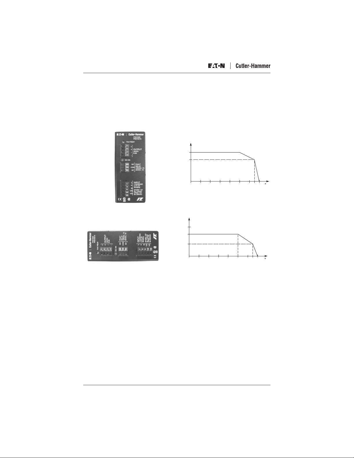
160 Watt Power Supply Temperature Derating and Mounting
Figure 4
Ver tical Mount
Out
6.0A
4.5A
Current
2.5A
Figure 5
Horizontal Mount
Out
6.0A
4.6A
Current
2.5A
10020304050
Te mperature
60 65 70
C
Page 2
10020304050
Te mperature
60 65 70 C
Effective 5/04

A
160W
Power
Supply
160W
Power
Supply
+
+
-
-
+
+
-
-
Use All Available "+" and "-"
Te rminals to Minimize Voltage Drop
Between Power Supply and Terminal
Blocks
Figure 6
Load Sharing Instructions for the PSS160E/C — Maximum 3 Units
1. Power up each unit and measure the output voltage to
make sure that they measure within 2V of each other.
Factory default should be sufficient but if any changes
have been made it is recommended to recheck output
voltage.
2. Wire up the outputs of each supply to a common terminal point. Make sure to keep the wire length from the
output of each supply to the common point as close in
length with one another as possible and, in addition, as
short as possible. This will reduce the load sharing
imbalance. Connect the load sharing terminals of each
supply together in parallel. That is, connect all of the
(+)s together and the (-)s together. The use of a twisted
pair is recommended but not necessary unless the
cabling is longer than 1m (3 ft.) or if there are many
noisy devices in close proximity (i.e., VFDs).
3. Turn on the AC and the units should be sharing the
load. Please note that you require a minimum load of
0.5A per power supply in order that the load sharing
works, otherwise you may get one or more supplies
shutting down. This is not a reason for concern, the
supply(s) that shut down will turn on as soon as the
load requirement increases.
4. The power supply total output should be derated to
85% of typical output since open loop load sharing is
being utilized. You can load share up to 3 units for a
total power output of 408W (16.6A at 24V DC).
Recommendation
(ventilation) between units.
+
24V DC
@ 11.3
-
: Please allow adequate space
Effective 5/04
Page 3

Pub 50255
Catalog Number PSS160E PSS160C
Output Specifications
Output Voltage Nominal 24V DC 24V DC
Voltage Regulation 22.5 – 28.5V DC 22.5 – 28.5V DC
Steady State Wattage 160W 160W
Steady State Output Current 6.5A 6.5A
Outrush Wattage (Nominal) 320W 320W
Outrush Current 13A 13A
Outrush Holdup Time 1 sec 1 sec
Maximum Capacitive Load 10,000 uF 10,000 uF
Surge Cycle Time 10 sec 10 sec
Overload Protection Overcurrent shutdown with automatic restart Overcurrent shutdown with automatic restart
Input Specifications
Input Voltage Nominal 115V AC/250V AC 480V AC
Voltage Range ±10% 342 – 528V AC
Input Frequency 47 – 63 Hz 47 – 63 Hz
Input Current 2.3/1.4A .36A
Input Protection
Inrush Current 30A 5.7A
Voltage Withstand 2 kV 4 kV
Fuse (External) (3) 2A 250V Fuse
Fuse (Internal) 6.3A (3)T 2A 250V Thermistor Lid
Switching Frequency 65 kHz 100 kHz
Efficiency (at Maximum Load) 85% 83%
Maximum Ripple ±0.2 RMS ±0.1 RMS
Operating Specifications
Dielectric Strength
Input to Output 3 kV AC 3 kV AC
Input/Output to DIN Rail 3 kV AC 3 kV AC
Input to Ground 1.5 kV AC 1.5 kV AC
Output to Ground 500V AC 500V AC
Temperature — Operating (No Derating) -4˚F – 122°F (-20˚C – 50°C) -4˚F – 122°F (-20˚C – 50°C)
Altitude (No Derating) 2,000m 2,000m
Operating Humidity 20 – 85% RH non-condensing 20 – 85% RH non-condensing
Vibration 3g 3g
RFI Specification Class A Class A
Degree of Protection (IEC 529) IP00 IP00
Wiring Specifications
Wire Size — Primary 20 – 12 AWG 20 – 12 AWG
Wire Size — Secondary 20 – 12 AWG 20 – 12 AWG
Insulation Stripping Length —
in Inches (mm)
Mounting Method See DIN Option PSSDIN See DIN Option PSSDIN
Panel Mount DIN Option Available See DIN Option PSSDIN See DIN Option PSSDIN
Dimensions and Weights
Mechanical Dimensions —
in Inches (mm)
Approximate Weight — in Lbs. (kg) 1.94 (0.880) 2.2 (0.993)
Standards
Certifications and Standards CE, cULus Listed CE, cULus Listed
— Storage -40˚F – 185°F (-40˚C – 85°C) -40˚F – 185°F (-40˚C – 85°C)
Clamp Screw Tightening Torque —
in lb-in (Nm)
Clamp Screw Tightening Torque —
in lb-in (Nm)
Output Connections 2 2
4.38 (0.5) 4.38 (0.5)
4.38 (0.5) 4.38 (0.5)
0.35 (9) 0.35 (9)
5.00W x 2.24H x 6.89D
(127W x 57H x 175D)
5.44W x 2.3H x 7.0D
(138W x 58H x 178D)
© 2004 Eaton Corporation
All Rights Reserved
Printed in USA
Effective 5/04
 Loading...