

Instruction Leaflet IL040029EN
Effective December 2017
Supersedes March 2014
PowerXL DH1 Series VFD
Instruction Leaflet Инструкция по монтажу Asennusohje Instrukcja montażu
Montageanweisung Montagehandleiding Návod k montáži Navodila za montažo
Notice d’installation Montagevejledning Paigaldusjuhend Návod na montáž
Instrucciones de montaje Οδηγίες εγκατάστασης Szerelési utasítás Монтажни инструкции
Istruzioni per il montaggio Instruções de montagem Montāžas instrukcija Instrucţiuni de montaj
ᆹ㻵䈤᰾ Monteringsanvisning Montavimo instrukcija
en
Electric Current! Danger to Life!
Only skilled or instructed persons may carry out the following operations.
de
Lebensgefahr durch elektrischen Strom!
Nur Elektrofachkräfte und elektrotechnisch unterwiesene Personen dürfen die im Folgenden beschriebenen Arbeiten ausführen.
fr
Tension électrique dangereuse !
Seules les personnes qualifiées et averties doivent exécuter les travaux ci-après.
es
¡Corriente eléctrica! ¡Peligro de muerte!
El trabajo a continuación descrito debe ser realizado por personas cualificadas y advertidas.
it
Tensione elettrica: Pericolo di morte!
Solo persone abilitate e qualificate possono eseguire le operazioni di seguito riportate.
zh
䀖⭥ড䲙ʽ
ݱ䇨уъӪઈ઼䗷уъ䇝㓳ⲴӪઈ䘋㹼 лࡇᐕDŽ
ru
Электрический ток! Опасно для жизни!
Только специалисты или проинструктированные лица могут выполнять следующие операции.
nl
Levensgevaar door elektrische stroom!
Uitsluitelijk deskundigen in elektriciteit en elektrotechnisch geinstrueerde personen is het toegestaan, de navolgend beschrevene werkzaamheden uit te voeren.
da
Livsfare på grund af elektrisk strøm!
Kun uddannede el-installatører og personer der e instruerede i elektrotekniske arbejdsopgaver, må udføre de nedenfor anførte arbejder.
el
Προσοχή, κίνδυνος ηλεκτροπληξίας!
Οι εργασίες που αναφέρονται στη συνέχεια θα πρέπει να εκτελούνται μόνο από ηλεκτρολόγους και ηλεκτροτεχνίτες.
pt
Perigo de vida devido a corrente eléctrica!
Apenas electricistas e pessoas com formação electrotécnica podem executar os trabalhos que a seguir se descrevem.
sv
Livsfara genom elektrisk ström!
Endast utbildade elektriker och personer som undervisats i elektroteknik får utföra de arbeten som beskrivs nedan.
Hengenvaarallinen jännite!
Vain pätevät sähköasentajat ja opastusta saaneet henkilöt saavat suorittaa seuraavat työt.
EATON www.eaton.com 1
Instruction Leaflet IL040029EN
Effective December 2017
PowerXL DH1 Series VFD
cs
Nebezpečí úrazu elektrickým proudem!
Níže uvedené práce smějí provádět pouze osoby s elektrotechnickým vzděláním.
et
Eluohtlik! Elektrilöögioht!
Järgnevalt kirjeldatud töid tohib teostada ainult elektriala spetsialist vői elektrotehnilise instrueerimise läbinud personal.
hu
Életveszély az elektromos áram révén!
Csak elektromos szakemberek és elektrotechnikában képzett személyek végezhetik el a következőkben leírt munkákat.
lv
Elektriskā strāva apdraud dzīvību!
Tālāk aprakstītos darbus drīkst veikt tikaielektrospeciālisti un darbam ar elektrotehniskām ekārtām instruētās personas!
lt
Pavojus
Tik elektrikai ir elektrotechnikos specialistai gali atlikti žemiau aprašytus darbus.
gyvybei
dėl elektros srovės!
pl
Porażenie prądem elektrycznym stanowi zagrożenie
dla życia!
Opisane poniżej prace mogą przeprowadzać tylko wykwalifikowani elektrycy oraz osoby odpowiednio poinstruowane w zakresie elektrotechniki.
sl
Življenjska nevarnost zaradi električnega toka!
Spodaj opisana dela smejo izvajati samo elektrostrokovnjaki in elektrotehnično poučene osebe.
sk
Nebezpečenstvo ohrozenia života elektrickým prúdom!
Práce, ktoré sú nižšie opísané, smú vykonávat’ iba elektroodborníci a osoby s elektrotechnickým vzdelaním.
bg
Опасност за живота от електрически ток!
Операциите, описани в следващите раздели, могат да се извършват само
от специалисти-електротехници и инструктиран електротехнически
персонал.
ro
Atenţie! Pericol electric!
Toate lucrările descrise trebuie efectuate numai de personal de specialitate calificat şi de persoane cu cunoştiinţe profunde în electrotehnică.
2 EATON www.eaton.com

PowerXL DH1 Series VFD
Instruction Leaflet IL040029EN
Effective December 2017
Series Power Part Options
D H1 – 3 4 011 N N – C 21 C
Basic naming
D = Drive
Series
G1 = General purpose
H1 = HVAC
DH1 - Output current rating (CT)
208–240 V 380–500 V 525–600 V
4D8 = 4.8A, 1.0HP, 0.75KW
6D6 = 6.6A, 1.5HP, 1.1KW
7D8 = 7.8A, 2.0HP, 1.5KW
011 = 11A, 3.0HP, 2.2KW
012 = 12.5A, - HP, 3.0KW
017 = 17.5A, 5.0HP, 3.7KW
025 = 25A, 7.5HP, 5.5KW
031 = 31A, 10HP, 7.5KW
048 = 48A, 15HP, 11KW
061 = 61A, 20HP, 15KW
075 = 75A, 25HP, 18.5KW
088 = 88A, 30HP, 22KW
114 = 114A , 40HP, 30KW
143 = 143A, 50HP, 37KW
170 = 170A, 60HP, 45KW
211 = 211A, 75HP, 55KW
261 = 261A, 100HP, 75KW
312 = 312A, 125HP, 90KW
Phase reference
3 = 3~ INPUT/3~ OUTPUT
Input/output voltage rating
2 = 230 V (208–240 V, –15%, +10%)
4 = 400 V (380–500 V, –15%, +10%)
5 = 600 V (525–600 V, –15%, +10%)
3D3 = 3.3A, 1.5HP, 1.1KW
4D3 = 4.3A, 2.0HP, 1.5KW
5D6 = 5.6, 3.0HP, 2.2KW
7D6 = 7.6A, 4.0HP, 3KW
9D0 = 9A, - HP, 4KW
012 = 12A, 7.5HP, 5.5KW
016 = 16A, 10HP, 7.5KW
023 = 23A, 15HP, 11KW
031 = 31A, 20HP, 15KW
038 = 38A, 25HP, 18.5KW
046 = 46A, 30HP, 22KW
061 = 61A, 40HP, 30KW
072 = 72A, 50HP, 37KW
087 = 87A, 60HP, 45KW
105 = 105A, 75HP, 55KW
140 = 140A, 100HP, 75KW
170 = 170A, 125HP, 90KW
205 = 205A, 150HP, 110KW
261 = 261A, 200HP, 132KW
310 = 310A, 250HP, 160KW
4D5 = 4.5A, 3HP, 2.2KW
7D5 = 7.5A, 5.0HP, 3.7KW
010 = 10A, 7.5HP, 5.5KW
013 = 13.5A, 10HP, 7.5KW
018 = 18A, 15HP, 11KW
022 = 22A, 20HP, 15KW
027 = 27A, 25HP, 18.5KW
034 = 34A, 30HP, 22KW
041 = 41A, 40HP, 30KW
052 = 52A, 50HP, 37KW
062 = 62A, 60HP, 45KW
080 = 80A, 75HP, 55KW
100 = 100A, 100HP, 75KW
125 = 125A, 125HP, 90KW
144 = 144A, 150HP, 110KW
208 = 208A, 200HP, 132KW
250 = 250A, 250HP, 160KW
Internal brake chopper
N = No brake chopper
B = Brake chopper
Internal EMC filter
D = DC choke only
E = EMC filter only
F = Internal EMC filter and DC choke
N = No EMC filter, no DC choke
C = Coated
Enclosure (IP rating)
00 = IP00/Open Type
20 = IP20/Open Type
21 = IP21/Type 1
54 = IP54/Type 12
Display option
C = LCD (graphical)
N = No display
Coating of boards
IP00 FR7 and FR8 is not avaliable for 230V input product or with the PowerXL DH1 Product
IP20 FR0 will be avalible in June 2018
EATON www.eaton.com 3

Instruction Leaflet IL040029EN
PowerXL DH1 Series VFD
Effective December 2017
Dimensions and weights—Dimensões e pesos—Encombrements et poids—Abmessungen und Gewichte—
Dimensioni e pesi—Afmetingen en gewichten—Dimensioner og vægt—Διαστάσεις και βάρη—
Dimensiones y pesos—Mått och vikter—Mitat ja painot—Rozměry a hmotnosti—Mõõdud ja kaalud—
Méretek és tömeg—Izmēri un svars—Matmenys ir masė—Wymiary i ciężary—Mere in teže—
Rozmery a hmotnosti—Размери и тегло—Dimensiuni şi greutăţi—Размеры и вес— ቪረ઼䟽䟿
H2
H1
Frame
Approximate dimensions in inches (mm)
size
FR0
FR1 7.91
FR2 9.63
FR3 10.44
FR4 11.57
FR5 13.41
FR6 14.61
Note
6.83
10.58
(173.5)
(268.7)
12.87
(327.0)
(200.9)
16.50
(419.0)
(244.7)
21.97
(558.0)
(265.1)
24.80
(630.0)
(294.0)
34.98
(888.5)
(340.7)
40.75
(371)
FR0 is not available till June 2018.
(1035)
W4
W3
10.16
(258.0)
12.28
(312.0)
15.98
(406.0)
21.46
(545.0)
24.31
(617.5)
29.65
(753.0)
33.27
(845)
9.54
(242.3)5(127.0)
11.50
(292.0)
14.96
(380.0)
20.41
(518.5)
23.26
(590.7)
27.83
(707.0)
31.38
(797)
6.02
(153.0)
6.61
(167.8)
8.06
(204.6)
9.36
(237.7)
11.34
(288.0)
19.13
(486)
4.97
(126.3)
4.80
(122.0)
5.28
(134.0)
7.24
(184.0)
9.13
(232.0)
11.10
(282.0)
18.90
(480)
D
4.26
(108.3)
3.94
(100.0)
3.54
(90.0)
4.92
(125.0)
8.07
(205.0)
8.66
(220.0)
15.75
(400)
4.26
(108.3)
3.94
(100.0)
3.54
(90.0)
4.92
(125.0)
8.07
(205.0)
8.66
(220.0)
15.75
(400)
H3
0.28
(7.0)
0.28
(7.0)
0.28
(7.0)
0.35
(9.0)
0.35
(9.0)
0.35
(9.0)
0.35
(9)
W2
W1
Weight
lb (kg)D H1 H2 H3 W1W2W3W4Ø
4.41
(2.0)
14.33
(6.5)
23.37
(10.6)
49.82
(22.6)
77.60
(35.2)
154.32
(70.0)
246.91
(112)
4 EATON www.eaton.com
PowerXL DH1 Series VFD
Instruction Leaflet IL040029EN
Effective December 2017
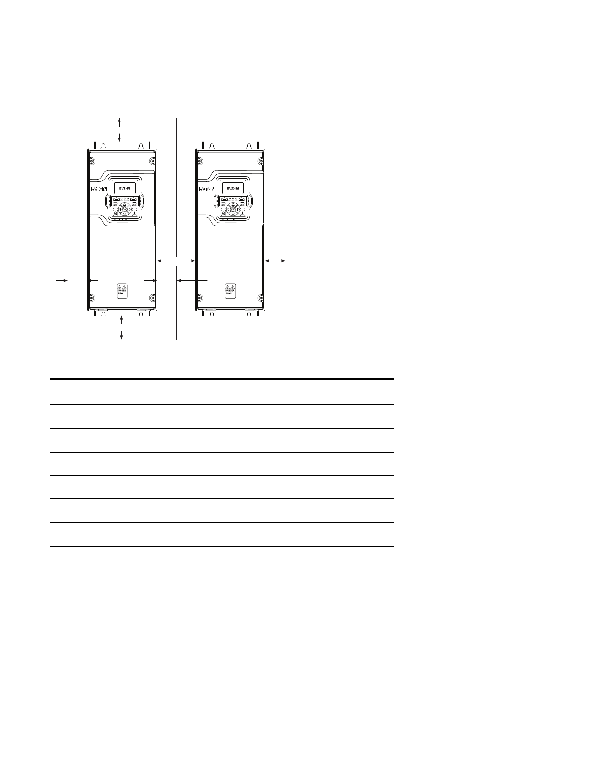
Mounting—Montaje—Montage—Montaggio—Montering—Τοποθέτηση—Montagem—Asennus—
Montáž—Paigaldamine—Felszerelése—Montāža—Montavimas—Montaż—Montaža—Монтаж—
Montarea—Монтаж— ᆹ㻵
C
B A
A
D
Frame
size
FR0
A
In (mm)
0 0 3.94
FR1 0.79
(20)
FR2 1.18
(30)
B
In (mm)
1.58
(40)
2.36
(60)
FR3 0 0 7.87
FR4 0 0 11.81
FR5 3.15
(80)
FR6 3.15
(80)
Notes
kW ratings are at 400 V / 50 Hz.
Minimum clearances A and B for drives with Type 12 (IP54) enclosure is 0 mm (in) for FR1, FR2, FR3, FR4, FR6.
The above guidelines apply unless testing has been completed to validate a design outside of these recommendations.
FR0 is not available till June 2018.
6.30
(160)
6.30
(160)
A
C
In (mm)
(100)
3.94
(100)
6.30
(160)
(200)
(300)
11.81
(300)
15.75
(400)
D
In (mm)
1.97
(50)
1.97
(50)
2.36
(60)
3.15
(80)
3.94
(100)
7.87
(200)
12.99
(330)
Cooling air required
CFM (m3/h)
16.5
(28)
14
(24)
55
(94)
85
(144)
153
(260)
232
(395)
230V: 435 (739)
480V/600V: 400 (679)
EATON www.eaton.com 5

Instruction Leaflet IL040029EN
Effective December 2017
PowerXL DH1 Series VFD
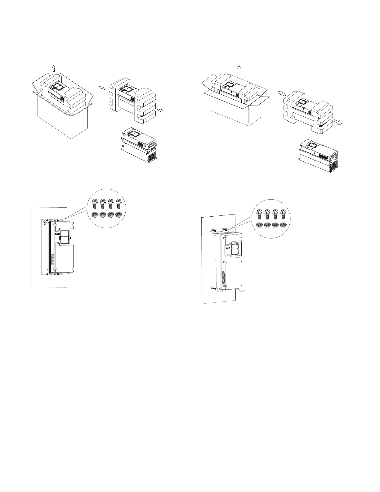
FR0 mounting instructions
Step 1: Lift the drive out from the carton, remove the packaging
Step 2: Attach the drive to the mounting plate with four M5X15
screws and four M5 nuts.The opening dimension on the
mounting plate should follow required dimension (refer
to the drive mounting template printed on the outside
carton)
The drive can be mounted vertically or horizontally
according to customer's need.
SCREW:4-M5*15
NUT:4-M5
FR1 mounting instructions
Step 1:
Step 2:
Screw: Four M5x15
or 3/16 inch
Nut: Four M5
or 3/16 inch
Vertical mounting
Horizontal mounting
Step 3: 1. EN version FR0 or US version FR0 with EMC kit
1)Input wiring: Run the L1,L2, L3 wires through a
magnetic ring and wind one lap, fix the L1,L2, L3 wires
and magnetic ring with a cable tie, then connect the
L1,L2, L3 wires to input terminals. Connect the input
grounding wire to the bottom metal plate with a M4*10
screw.)
Output wiring: a ttach a L shape EMC grounding plate to
the bottom of drive with two M4*8 flat screws. Connect
the output U, V, W wires to output terminals. Connect
the output grounding wire to the bottom metal plate
with a M4*10 screw. Clamp the output cable shield to
the L shape EMC grounding plate with a small
rectangular EMC grounding plate and two M4*15
screws.
2. US version FR0 without EMC kit, there are no
magnetic ring and EMC grounding plates, but it is
necessary to connect the output cable shield to the
bottom metal surface with a M4*10 screw
SCREW: 2-M4*10
SCREW: 2-M4*8flat
SCREW: 2-M4*15
Output cable
Magnetic ring
Cable tie
Input power wires
Input grounding wire
Note
FR0 is not available till June 2018.
6 EATON www.eaton.com
PowerXL DH1 Series VFD
Instruction Leaflet IL040029EN
Effective December 2017
FR2 mounting instructions
Step 1:
Step 2:
FR3 mounting instructions
Step 1:
Step 2:
Screw: Four M5x15
or 3/16 inch
Nut: Four M5
or 3/16 inch
Screw: Four M6x15
or 1/4 inch
Nut: Four M6
or 1/4 inch
EATON www.eaton.com 7

Instruction Leaflet IL040029EN
Effective December 2017
FR4 mounting instructions
Step 1:
PowerXL DH1 Series VFD
Step 2:
Screw: Four M8x15
or 3/8 inch
Nut: Four M8
or 3/8 inch
8 EATON www.eaton.com

PowerXL DH1 Series VFD
FR5 mounting instructions
Step 1:
Step 2:
Instruction Leaflet IL040029EN
Effective December 2017
Step 3:
Step 4:
Screw: Four M8x20
or 3/8 inch
Nut: Four M8
or 3/8 inch
EATON www.eaton.com 9

Instruction Leaflet IL040029EN
Effective December 2017
FR6 mounting instructions
Step 1: Remove the carton from the drive.
PowerXL DH1 Series VFD
Step 4: Attach the drive to the mounting plate with four
M8x20 or 3/8-inch screws and four M8 or 3/8-inch
nuts with an M8 or 2/8-inch wrench. The opening
dimensions on the mounting plate should follow
required dimensions (refer to the drive mounting
template printed on the outside carton).
SCREW:4-M8*20
NUT:4-M8
Step 2: Remove the four screws (used to fix the drive to
the pallet) with an M8 or 3/8-inch wrench.
Step 3: Use a hook to lift the drive.
10 EATON www.eaton.com

PowerXL DH1 Series VFD
Warning!
en
Connect only in voltage-free state!
Instruction Leaflet IL040029EN
Effective December 2017
es
¡Advertencia!
¡Conectar únicamente en estado sin tensión!
fr
Avertissement !
Raccordez l’appareil uniquement hors tension !
de
Warnung!
Nur im spannungsfreien Zustand anschließen!
it
Avvertimento!
Collegare solo in assenza di tensione!
nl
Waarschuwing!
Alleen in spanningsloze toestand aansluiten!
da
Advarsel!
Må kun tilsluttes i spændingsfri tilstand!
el
Προειδοποίηση!
Συνδέστε μόνο όταν δεν επικρατεί τάση!
pt
Atenção!
Ligar apenas com a tensão desligada!
sv
Varning!
Får endast anslutas i spänningsfritt tillstånd!
Varoitus!
Kytke vain jännitteettömässä tilassa!
cs
Varování!
Připojujte jen při zcela odpojeném napájení!
et
Hoiatus!
Ühendada ainult pingevabas olekus!
hu
Figyelmeztetés!
Csak feszültségmentes állapotban csatlakoztassa!
lv
Brīdinājums!
Pieslēgt tikai tad, kad nenotiek sprieguma padeve!
lt
Perspėjimas!
Prijungti tik tada, kai išjungta įtampa!
pl
Ostrzeżenie!
Podłączać zawsze po uprzednim odłączeniu od zasilania elektrycznego!
sl
Opozorilo!
Napravo priključite le, ko ni pod napetostjo!
sk
Varovanie!
Napájat˙ len v stave bez napätia!
bg
Предупреждение!
Свързвайте само, когато уреда не е под напрежение!
ro
Atenţie!
Conectaţi doar când aparatul nu se află sub tensiune!
ru
Предупреждение!
Подключать только в обесточенном состоянии!
zh
䆖
ᗵ享൘ᯝ⭥⣦ᘱл䘋㹼䘎᧕ʽ
Ground wiring
(FR1–FR4)
No. 2 Phillips
(FR5)
No. 3 Phillips
(FR1–FR3)
PE
15
(FR1–FR3)
25
(FR4–FR6)
M4, 10 in-lb (1.1 Nm)
(FR4)
M4, 14 in-lb (1.6 Nm)
(FR5)
M6, 35 in-lb (4.0 Nm)
EATON www.eaton.com 11

Instruction Leaflet IL040029EN
Effective December 2017
Rubber grommet installation instructions
PowerXL DH1 Series VFD
Step 1:
D1 (Cable)
Step 2:
D2 (Grommet)
Step 3:
D1 ≤ D2 ≤ D1 + 2 mm
Step 5:
Step 6:
Step 4:
Self-Locking Cable Ties
12 EATON www.eaton.com

PowerXL DH1 Series VFD
Input power and motor cable stripping lengths
Instruction Leaflet IL040029EN
Effective December 2017
Frame
Size
FR0
FR1 0.39
FR2 0.59
FR3 0.59
FR4 0.98
FR5 1.10
FR6 0.98
Power connection tightening torque
Frame
Size
FR0
Power Wiring in Inches (mm) Motor Wiring in Inches (mm)
A1 B1 C1 D1 A2 B2 C2 D2
0.39
(10)
(10)
(15)
(15)
(25)
(28)
(25)
Power wire
in-lb (Nm)
5.3 (0.6) 14 (1.6) 4.5 (0.5)
5.12
(130)
1.77
(45)
1.77
(45)
1.57
(40)
2.56
(65)
6.10
(155)
4.72
(120)
0.39
(10)
0.39
(10)
0.59
(15)
0.59
(15)
0.98
(25)
1.10
(28)
0.98
(25)
5.12
(130)
1.38
(35)
1.77
(45)
1.97
(50)
4.72
(120)
9.45
(240)
7.87
(200)
Ground wire
in-lb (Nm)
0.39
(10)
0.39
(10)
0.59
(15)
0.59
(15)
0.98
(25)
1.10
(28)
0.98
(25)
Control wire
in-lb (Nm)
FR1 5.3 (0.6) 10 (1.1) 4.5 (0.5)
FR2 15.6 (1.8) 10 (1.1) 4.5 (0.5)
FR3 40 (4.5) 10 (1.1) 4.5 (0.5)
FR4 95 (10.7) 14 (1.6) 4.5 (0.5)
FR5 354 (40.0) 35 (4.0) 4.5 (0.5)
FR6 480 (54.2) 35 (4.0) 4.5 (0.5)
Notes
Strip the motor and power cables as shown above.
Both UL® and IEC tools may be used.
Applies to strained wire, solid wire, or ferrule installations.
FR0 is not available till June 2018.
3.15
(80)
1.77
(45)
1.57
(40)
1.57
(40)
2.56
(65)
6.10
(155)
4.72
(120)
0.39
(10)
0.39
(10)
0.59
(15)
0.59
(15)
0.98
(25)
1.10
(28)
0.98
(25)
1.97
(50)
1.38
(35)
1.57
(40)
1.97
(50)
4.72
(120)
9.45
(240)
7.87
(200)
EATON www.eaton.com 13

Instruction Leaflet IL040029EN
PowerXL DH1 Series VFD
Effective December 2017
Cable and fuse guidelines
North America cable and fuse sizes—208 Vac to 240 Vac ratings
NEC
motor amp
rating
at 208 V
Frame size
FR0
Amp
suffix
208 V
input
current
(VT/I
)
L
NEC
motor amp
rating
at 230 V
4D8 5.6 4.2 4.6 4.8 10 14 14 26–10 18–10
6D6 7.6 6 6.6 6.6 10 14 14 26–10 18–10
7D8 9 6.8 7.5 7.8 15 14 14 26–10 18–10
FR1 4D8 4.4 4.2 4.6 4.8 10 14 14 24–10 18–10
6D6 6.1 6 6.6 6.6 10 14 14 24–10 18–10
7D8 7.2 6.8 7.5 7.8 10 14 14 24–10 18–10
011 10.2 9.6 10.6 11 15 14 14 24–10 18–10
012 11.6 — — 12.5 15 12 12 24–10 18–10
FR2 017 16.3 15.2 16.7 17.5 20 10 10 20–6 12–6
025 23.2 22 24.2 25 30 8 10 20–6 12–6
031 29 28 30.8 31 35 8 10 20–6 12–6
FR3 048 44.2 42 46.2 48 60 6 6 6–2 14–4
061 56 54 59.4 61 80 4 6 6–2 14–4
FR4 075 64.6 68 74.8 75 100 3 4 6–1/0 10–1/0
088 78 80 88 88 110 2 4 6–1/0 10–1/0
114 94.3 104 114 114 125 1/0 3 6–1/0 10–1/0
FR5 143 129 130 143 143 175 3/0 3 1/0–350 kcmil 8–250 kcmil
170 157 154 169 170 200 4/0 3 1/0–350 kcmil 8–250 kcmil
211 189 192 211 211 250 300 3 1/0–350 kcmil 8–250 kcmil
FR6 261 242.8 248 273 261 400 2*2/0 3 2*(1/0–300 kcmil) 3–300 kcmil
312 290.3 312 343 312 400 2*4/0 3 2*(1/0–300 kcmil) 3–300 kcmil
Notes
Line and motor cable size is selected according to UL 508C Table 40.3 for copper conductor rated 75 °C. Use only with copper wire rated 75 °C here.
Size requirements for other different wire types are defined in the National Electrical Code
Earthing conductor size is determined by the maximum overcurrent device rating used ahead of the drive according to UL 508C Table 6.4.
If power cubes or bypass are used, a UL listed Class RK5, J, T or equivalent fuse is recommended.
FR0 is not available till June 2018.
Current
(VT/I
)
L
at 40 °C
®
, ANSI/NFPA® 70.
Recommended
fuse
rating
NEC®
wire size (AWG) Terminal connection size (AWG)
Line and
motor Ground
Line and
motor Ground
14 EATON www.eaton.com

PowerXL DH1 Series VFD
Instruction Leaflet IL040029EN
Effective December 2017
International cable and fuse sizes—208 Vac to 240 Vac Ratings
Frame size
FR0
Amp
suffix
current
(VT/I
L
)
4D8 5.6 4.8 10 3*1.5+1.5 0.2–6 solid or
208 V input
Current
)
(VT/I
L
at 40 °C
Fuse
rating
(gG/gL)
Mains and
motor cable
Cu (mm
2
)
Terminal cable size
Main terminal
Cu (mm2)
Earth terminal
Cu (mm2)
0.75–6
0.2–4 stranded
6D6 7.6 6.6 10 3*1.5+1.5 0.2–6 solid or
0.75–6
0.2–4 stranded
7D8 9 7.8 16 3*1.5+1.5 0.2–6 solid or
0.75–6
0.2–4 stranded
FR1 4D8 4.4 4.8 6 3*1.5+1.5 0.2–6 solid or
0.75–6
0.2–4 stranded
6D6 6.1 6.6 10 3*1.5+1.5 0.2–6 solid or
0.75–6
0.2–4 stranded
7D8 7.2 7.8 16 3*1.5+1.5 0.2–6 solid or
0.75–6
0.2–4 stranded
011 10.2 11 16 3*1.5+1.5 0.2–6 solid or
0.75–6
0.2–4 stranded
012 11.6 12.5 16 3*1.5+1.5 0.2–6 solid or
0.75–6
0.2–4 stranded
FR2 017 16.3 17.5 20 3*4+4 0.5–16 4–16
025 23.2 25 32 3*4+4 0.5–16 4–16
031 29 31 32 3*6+6 0.5–16 4–16
FR3 048 44.2 48 50 3*16+16 16–35 2.5–25
061 56 61 63 3*16+16 16–35 2.5–25
FR4 075 64.6 75 80 3*25+16 16–50 6–50
088 78 88 100 3*35+16 16–50 6–50
114 94.3 114 125 3*50+25 16–50 6–50
FR5 143 129 143 160 3*70+35 50–185 10–120
170 157 170 200 3*95+50 50–185 10–120
211 189 211 250 3*150+95 50–185 10–120
FR6 261 242.8 261 400 2*(3*70+35) 2*(50–150) 35–150
312 290.3 312 400 2*(3*95+50) 2*(50–150) 35–150
Notes
Line and motor cable size is selected according to IEC 60364-5-52:2009 Table B.52.4 for copper conductor with PVC insulation with a wiring condition of ambient temperature 30 °C in air and an installation
method of “B2” (cables in conduit and cable trunking systems). For other wiring conditions, please refer to the standard of IEC 60364-5-52:2009 for suitable cable sizes.
Earthing conductor size is determined by the cross-sectional area of phase conductors according to IEC/EN 61800-5-1:2007 Table 5. So if phase conductor size is changed, earthing conductor size should also be changed accordingly.
If power cubes or bypass are used, a Class gG/gL fuse is recommended.
FR0 is not available till June 2018.
EATON www.eaton.com 15

Instruction Leaflet IL040029EN
Effective December 2017
PowerXL DH1 Series VFD
North America cable and fuse sizes—440 Vac to 500 Vac ratings
Current
(VT/I
at 40 °C
Frame size
FR0
Amp
suffix
Input current
(VT/IL)
amp rating
at 460 V
3D3 3.8 3 3 10 14 14 26–10 18–10
NEC motor
NEC
)
L
fuse
rating
Recommended
wire size (AWG)
Line and
motor Ground
Terminal connection
size (AWG)
Line and
motor Ground
4D3 4.3 3.4 3.4 10 14 14 26–10 18–10
5D6 6 4.8 4.8 10 14 14 26–10 18–10
7D6 9.6 7.6 7.6 15 14 14 26–10 18–10
FR1 3D3 2.8 3 3 10 14 14 26–10 18–10
4D3 3.2 3.4 3.4 10 14 14 26–10 18–10
5D6 4.5 4.8 4.8 10 14 14 26–10 18–10
7D6 7.1 7.6 7.6 10 14 14 26–10 18–10
9D0 8.4 — 7.6 15 14 14 26–10 18–10
012 10.2 11 11 15 14 14 26-10 18–10
FR2 016 13 14 14 20 12 12 20–6 12–6
023 19.6 21 21 30 10 10 20–6 12–6
031 25.2 27 27 35 8 8 20–6 12–6
FR3 038 31.7 34 34 50 6 8 6–2 14–4
046 37 40 40 60 6 8 6–2 14–4
061 48.1 52 52 80 4 6 6–2 14–4
FR4 072 59.3 65 65 100 4 4 6–1/0 10–1/0
087 70.3 77 77 110 3 4 6–1/0 10–1/0
105 87.6 96 96 125 1 3 6–1/0 10–1/0
FR5 140 114.4 124 124 175 2/0 3 1/0–350 kcmil 8–250 kcmil
170 144 156 156 200 3/0 3 1/0–350 kcmil 8–250 kcmil
205 166.1 180 180 250 250 kcmil 3 1/0–350 kcmil 8–250 kcmil
FR6 261 226.4 240 240 400 2*2/0 3 2*(1/0–300 kcmil) 3–300 kcmil
310 284.9 302 302 400 2*4/0 3 2*(1/0–300 kcmil) 3–300 kcmil
Notes
Line and motor cable size is selected according to UL 508C Table 40.3 for copper conductor rated 75 °C. Use only with copper wire rated 75 °C here.
Size requirements for other different wire types are defined in the National Electrical Code, ANSI/NFPA 70.
Earthing conductor size is determined by the maximum overcurrent device rating used ahead of the drive according to UL 508C Table 6.4.
If power cubes or bypass are used, a UL listed Class RK5, J, T or equivalent fuse is recommended.
FR0 is not available till June 2018.
16 EATON www.eaton.com

PowerXL DH1 Series VFD
Instruction Leaflet IL040029EN
Effective December 2017
International cable and fuse sizes—380 Vac to 440 Vac ratings
Frame size
FR0
Amp
suffix
current
(VT/I
L
)
3D3 4.3 3.3 6 3*1.5+1.5 0.2–6 solid or
400 V input
Current
)
(VT/I
L
at 40 °C
Fuse
rating
(gG/gL)
Mains and motor
cable Cu (mm
2
)
Terminal cable size
Main terminal
Cu (mm2)
Earth terminal
Cu (mm2)
0.75–6
0.2–4 stranded
4D3 5.5 4.3 10 3*1.5+1.5 0.2–6 solid or
0.75–6
0.2–4 stranded
5D6 7.1 5.6 10 3*1.5+1.5 0.2–6 solid or
0.75–6
0.2–4 stranded
7D6 9.6 7.6 16 3*1.5+1.5 0.2–6 solid or
0.75–6
0.2–4 stranded
FR1 3D3 3.1 3.3 6 3*1.5+1.5 0.2–6 solid or
4D3 4 4.3 6 3*1.5+1.5 0.75–6
0.2–4 stranded
0.75–6
5D6 5.2 5.6 10 3*1.5+1.5 0.75–6
7D6 7.1 7.6 16 3*1.5+1.5 0.75–6
9D0 8.4 9 16 3*1.5+1.5 0.75–6
012 11.2 12 16 3*1.5+1.5 0.75–6
FR2 016 15 16 20 3*4+4 0.5–16 4–16
023 21.5 23 25 3*4+4 0.5–16 4–16
031 29 31 32 3*6+6 0.5–16 4–16
FR3 038 35.2 38 40 3*16+16 16–35 2.5–25
046 42.6 46 50 3*16+16 16–35 2.5–25
061 55.7 61 63 3*16+16 16–35 2.5–25
FR4 072 65.7 72 80 3*25+16 16–50 6–50
087 79.4 87 100 3*35+16 16–50 6–50
105 97 105 125 3*50+25 16–50 6–50
FR5 140 129 140 160 3*70+35 50–185 10–120
170 157 170 200 3*95+50 50–185 10–120
205 189 205 250 3*120+70 50–185 10–120
FR6 261 246.2 261 400 2*(3*70+35) 2*(50–150) 35–150
310 292.4 310 400 2*(3*95+50) 2*(50–150) 35–150
Notes
Line and motor cable size is selected according to IEC 60364-5-52:2009 Table B.52.4 for copper conductor with PVC insulation with a wiring condition of ambient temperature 30 °C in air and an installation
method of “B2” (cables in conduit and cable trunking systems). For other wiring conditions, please refer to the standard of IEC 60364-5-52:2009 for suitable cable sizes.
Earthing conductor size is determined by the cross-sectional area of phase conductors according to IEC/EN 61800-5-1:2007 Table 5. So if phase conductor size is changed, earthing conductor size should also be changed accordingly.
If power cubes or bypass are used, a Class gG/gL fuse is recommended.
FR0 is not available till June 2018.
EATON www.eaton.com 17

Instruction Leaflet IL040029EN
Effective December 2017
PowerXL DH1 Series VFD
North America cable and fuse sizes—525 Vac to 600 Vac ratings
NEC wire
Size (AWG) Terminal connection size (AWG)
Frame size Amp suffix
575 V input
current (VT/IL)
NEC motor amp
rating at 575 V
Current (VT/I
at 40 °C
)
Recommended
L
fuse rating
Line and
motor Ground Line and motor Ground
FR1 4D5 4.2 3.9 4.5 10 14 14 26–10 18–10
7D5 7 6.1 7.5 10 14 12 26–10 18–10
010 9.3 9 10 15 14 10 26–10 18–10
FR2 013 12.5 11 13.5 20 12 10 20–6 12–6
018 16.7 17 18 30 10 10 20–6 12–6
022 20.4 22 22 35 10 8 20–6 12–6
FR3 027 25.2 27 27 40 6 8 6–2 14–4
034 31.7 32 34 45 6 8 6–2 14–4
041 38.2 41 41 50 6 6 6–2 14–4
FR4 052 48.1 52 52 70 4 6 6–1/0 10–1/0
062 57.4 62 62 80 4 6 6–1/0 10–1/0
080 73 77 80 125 2 4 6–1/0 10–1/0
FR5 100 91.3 99 100 150 1/0 4 1/0–350 kcmil 8–250 kcmil
125 114.1 125 125 175 2/0 4 1/0–350 kcmil 8–250 kcmil
144 132.9 144 144 200 3/0 4 1/0–350 kcmil 8–250 kcmil
FR6 208 202.8 192 208 400 2*1/0 3 2*(1/0–300 kcmil) 3–300 kcmil
250 243.8 242 250 400 2*2/0 3 2*(1/0–300 kcmil) 3–300 kcmil
Notes
Line and motor cable size is selected according to UL 508C Table 40.3 for copper conductor rated 75 °C. Use only with copper wire rated 75 °C here.
Size requirements for other different wire types are defined in the National Electrical Code, ANSI/NFPA 70.
Earthing conductor size is determined by the maximum overcurrent device rating used ahead of the drive according to UL 508C Table 6.4.
If power cubes or bypass are used, a UL listed Class RK5, J, T or equivalent fuse is recommended.
18 EATON www.eaton.com

PowerXL DH1 Series VFD
Instruction Leaflet IL040029EN
Effective December 2017
EATON www.eaton.com 19

Instruction Leaflet IL040029EN
Effective December 2017
Control board layout
PowerXL DH1 Series VFD
Fan Power Wire
STO
AI Mode Selection
Control I/O
Terminals
Removable
EMC Screw
Connect DSP Part
to Power Board
Keypad
AUTO
AUTO
123
ON
OFF HAND
Connect MCU Part
to Power Board
Battery (Standard)
RJ45, BACnet,
IP Modbus TCP
Optional Card A
Optional Card B
ON
1
RS-485 Terminating
Resistor
Removable
MOV Screw
Line Ground
Clamp Location
Grounding
Strap Location
Line Side Motor
20 EATON www.eaton.com
Motor Ground
Clamp Location
Grounding
Strap Location

PowerXL DH1 Series VFD
Instruction Leaflet IL040029EN
Effective December 2017
Factory-set control terminal functions
I/O connection
External wiring Pin Signal name Signal Default setting Description
1 +10 V Ref. Output Voltage — 10 Vdc Supply Source
Res
2 AI1+
Analog Input 1 0–10 V Voltage Speed Reference (Programmable to 4 mA to 20 mA)
3 AI1– Analog Input 1 Ground — Analog Input 1 Common (Ground)
4 AI2+
i
5 AI2– Analog Input 2 Ground — Analog Input 2 Common (Ground)
Analog Input 2 4 mA to 20 mA Current Speed Reference (Programmable to 0–10 V)
6 GND I/O Signal Ground — I/O Ground for Reference and Control
7 DIN5 Digital Input 5 Preset Speed B0 Sets frequency output to Preset Speed 1
8 DIN6 Digital Input 6 Preset Speed B1 Sets frequency output to Preset Speed 2
9 DIN7 Digital Input 7 Emergency Stop (TI–) Input forces VFD output to shut off
10 DIN8 Digital Input 8 Force Remote (TI+) Input takes VFD from Local to Remote
11 CMB DI5 to DI8 Common Grounded Allows source input
12 GND I/O Signal Ground — I/O Ground for Reference and Control
13 24 V +24 Vdc Output — Control voltage output (100 mA max.)
14 DO1 Digital Output 1 Ready Shows the drive is ready to run
15 24 Vo +24 Vdc Output — Control voltage output (100 mA max.)
16 GND I/O Signal Ground — I/O Ground for Reference and Control
17 AO1+ Analog Output 1 Output Frequency Shows Output frequency to motor 0–60 Hz (4 mA to 20 mA)
18 AO2+ Analog Output 2 Motor Current Shows Motor current of motor 0–FLA (4 mA to 20 mA)
19 24 Vi +24 Vdc Input — External control voltage input
20 DIN1 Digital Input 1 Run Forward Input starts drive in forward direction (start enable)
21 DIN2 Digital Input 2 Run Reverse Input starts drive in reverse direction (start enable)
22 DIN3 Digital Input 3 External Fault Input causes drive to fault
23 DIN4 Digital Input 4 Fault Reset Input resets active faults
24 CMA DI1 to DI4 Common Grounded Allows source input
25 A/+ RS-485 Signal A — Fieldbus Communication (Modbus, BACnet)
26 B/- RS-485 Signal B — Fieldbus Communication (Modbus, BACnet)
27 R3NO Relay 3 Normally Open At Speed Relay output 3 shows VFD is at Ref. Frequency
28 R1NC Relay 1 Normally Closed Run Relay output 1 shows VFD is in a run state
29 R1CM Relay 1 Common
30 R1NO Relay 1 Normally Open
31 R3CM Relay 3 Common At Speed Relay output 3 shows VFD is at Ref. Frequency
32 R2NC Relay 2 Normally Closed Fault Relay output 2 shows VFD is in a fault state
33 R2CM Relay 2 Common
34 R2NO Relay 2 Normally Open
Notes
The above wiring demonstrates a SINK configuration. It is important that CMA and CMB are wired to ground (as shown by dashed line). If a SOURCE configuration is desired,
wire 24 V to CMA and CMB and close the inputs to ground. When using the +10 V for AI1, it is important to wire AI1—to ground (as shown by dashed line). If using +10 V for
AI1 or AI2, terminals 3, 5, and 6 need to be jumpered together.
AI1+ and AI2+ block that it can support 10K potentiometer.
EATON www.eaton.com 21

Instruction Leaflet IL040029EN
Effective December 2017
ଋጲڎ
PowerXL DH1 Series VFD
1PXFS9-ጆѴú% ଌ҃ଋጲڎ
H
ᑭ ֵଠᤗζՁՏሥ Ѣԇ᳭ᝢϘζՁ
1 +10V
2 AI1+
Res
3 AI1–
4 AI2+
i
5 AI2–
6GND
7 DIN5
8 DIN6
9 DIN7
10 DIN8
11 CMB
12 GND
13 24V
14 DO1
15 24Vo
16 GND
17 AO1+
18 AO2+
19 24Vi
20 DIN1
21 DIN2
22 DIN3
23 DIN4
24 CMA
25 A/+
26 B/-
27 R3NO
28 R1NC
29 R1CM
30 R1NO
31 R3CM
32 R2NC
33 R2CM
34 R2NO
ԟᏥᣤѢႂԌ
ഴᣤЙ1
ഴᣤЙ1ଋڠ
ഴᣤЙ2
ഴᣤЙ2ଋڠ
I/OζՁଋڠ
ஜߙᣤЙ5
ஜߙᣤЙ6
ஜߙᣤЙ7
ஜߙᣤЙ8
DI5ᒯDI8ၸ
I/O ζՁଋڠ
+24 Vdc ᣤѢ
ஜߙᣤѢ1
+24Vdc ᣤѢ
I/OζՁଋڠ
ഴᣤѢ1
ഴᣤѢ2
+24VDC ᣤЙ
ஜߙᣤЙ1
ஜߙᣤЙ2
ஜߙᣤЙ3
ஜߙᣤЙ4
DI1ᒯDI4ၸ
RS-485 ζՁA
RS-485 ζՁB
ፘႂ٧3 ࣡
ፘႂ٧1࣡
ፘႂ٧1ၸ
ፘႂ٧1࣡
ፘႂ٧3ၸ
ፘႂ٧2࣡
ፘႂ٧2ၸ
ፘႂ٧2࣡
-
0-10V
-
4-20mA
-
-
ᮔᤳB0
ᮔᤳB1
ጊপϢᢻ
҃ᤉር
ࣂଋڠ
-
-
эܫࡂ
-
-
ᣤѢᮟည
ႂႂึ
-
ൣՓᤁᛠ
ԥՓᤁᛠ
ܰᦉᬩ
ᬩܬ
ࣂଋڠ
-
-
Ҫᤳ
ᤁᛠ
Ҫᤳ
ᬩ
10 Vdc ႂຸ
ႂԌᤳԟᏥԺᎃር˝4-20mAὈ
ၸଋڠὈ
ഴᣤЙ
ႂึᤳԟᏥԺᎃር˝0-10VὈ
ഴᣤЙ2 ၸଋڠὈ
I/O ଋڠὋၸԟᏥ֖ଌ҃
߿ᮟညᣤѢᒯᮔᤳ1
߿ᮟညᣤѢᒯᮔᤳ2
ᣤЙ҃VFDᣤѢС
ᣤЙ࠱VFDఴڠԪ˝ᤉር
ЉႂຸᣤЙ
I/OଋڠὋၸԟᏥ֖ଌ҃
ଌ҃ႂԌᣤѢణܷϘ100mAὈ
௬ᇧԪᮟ٧ࣂэܫݝᤁᛠ
ଌ҃ႂຸᣤѢ 100mAὈ
I/OଋڠὋၸԟᏥ֖ଌ҃
௬ᇧႂᄉᣤѢᮟည 0-60Hz 4-20mAὈ
௬ᇧႂᄉႂႂึ 0-FLA (4-20mA)
ܰᦉଌ҃ႂԌᣤЙ
ᣤЙൣՓᡐҮԪᮟ٧ᡐҮըၸὈ
ᣤЙԥՓᡐҮԪᮟ٧ᡐҮըၸὈ
ᣤЙᤴԪᮟ٧Ԧၶᬩ
ᣤЙܬథᬩ
ЉႂຸᣤЙ
ဗڣጲᝬModbusὋ BACnetὈ
ဗڣጲᝬModbusὋ BACnetὈ
ፘႂ٧ᣤѢ3௬ᇧVFDܪԟᏥᮟည
ፘႂ٧ᣤѢ1௬ᇧVFDܪᤁᛠ࿃খ
ፘႂ٧ᣤѢ3௬ᇧVFDܪԟᏥᮟည
ፘႂ٧ᣤѢ2௬ᇧVFDܪᬩ࿃খ
22 EATON www.eaton.com

PowerXL DH1 Series VFD
Instruction Leaflet IL040029EN
Effective December 2017
A/+
A/-
EATON www.eaton.com 23

Instruction Leaflet IL040029EN
Effective December 2017
Caution!
en
In the territory of the EU Directive, the frequency-controlled devices and their accessories must be taken into operation only when the machine has been determined to fulfill the protection requirements of Machinery Safety Directive 89/392/EEC.
Ensure EMC-compliant installation. Lay control and communication cables spatially separated from the motor cable.
Ensure a large contact area connection between
cable screen and PE.
p
PowerXL DH1 Series VFD
es
¡Atención!
En el campo de aplicación de la normativa CE, los dispositivos controlados por
frecuencia y sus correspondientes accesorios sólo deberán ponerse en
marcha cuando se asegure que la máquina cumple con las exigencias de
seguridad de la normativa de máquinas 89/392/CEE.
El montaje debe cumplir CEM. Los cables de mando y de conexión a red se
deben instalar independientemente del cable de conexión al motor. El cable
apantallado
contacto.
fr
En application des directives européennes, les convertisseurs de fréquence et leurs accessoires ne doivent être mis en service que s’il a été vérifié que la machine répond aux exigences de la directive machines 89/392/CEE.
Montage conforme aux règles de la CEM. Eloigner les câbles de commande et de réseau des câbles puissance. Relier le blindage au PE en assurant de grandes surfaces de contact.
de
Im Geltungsbereich der EG-Richtlinien dürfen die frequenzgesteuerten Geräte und deren Zubehör nur dann in Betrieb genommen werden, wenn festgestellt wird, dass die Maschine die Schutzanforderungen der Maschinenrichtlinie 89/392/EWG erfüllt.
EMV-gerechter Aufbau. Steuer- und Netzleitungen räumlich getrennt von der
Motorleitung verlegen.
it
Nel campo di validità delle direttive CE, gli apparecchi a controllo di frequenza e i loro accessori possono essere messi in esercizio soltanto se si verifica che la macchina soddisfa i requisiti di sicurezza della direttiva macchine 89/392/CEE
Montaggio secondo CEM. Disporre i cavi comandi e di alimentazione separati
dal cavo del motore. Collegare lo schermo del cavo
superficie.
nl
Binnen het geldigheidsgebied van de EC-richtlijnen mogen de
frequentiegeregelde apparaten en de toebehoren daarvan alleen in bedrijf
worden genomen, wanneer wordt vastgesteld, dat de machine aan de
veiligheidseisen van de machinerichtlijn 89/392/EWG voldoet.
EMC-conforme constructie. Besturings- en netkabels ruimtelijk gescheiden van
de motorkabel leggen.
verbinden.
da
I det område, hvor EF-direktiverne er gældende, må det frekvensstyrede udstyr og dets tilbehør kun tages i anvendelse, hvis det konstateres, at maskinen opfylder beskyttelseskravene i maskindirektivet 89/392/EØF.
EMC-korrekt installation. Træk styre- og netledninger rumligt adskilt fra
motorledningen.
ledningsafskærmning og PE.
el
Στο πεδίο εφαρμογής των οδηγιών της ΕΚ, οι ελεγχόμενες μέσω συχνότητας
συσκευές και τα παρελκόμενά τους επιτρέπεται να τίθενται σε λειτουργία μόνο
εφόσον διαπιστωθεί ότι το μηχάνημα πληροί τις απαιτήσεις προστασίας της
οδηγίας της ΕΚ για τα μηχανήματα 89/392/ΕΟΚ.
Κατασκευή σύμφωνα με τις απαιτήσεις ΗΜΣ. Εγκαθιστάτε τους αγωγούς
ελέγχου και δικτύου
θωράκιση των αγωγών σε μεγάλη επιφάνεια με τη γείωση.
se debe conectar a masa utilizando una amplia superficie de
p
Attention !
Vorsicht!
Leitungsschirm großflächig mit PE verbinden.
p
Attenzione!
con PE con un’ampia
p
Voorzichtig!
Kabelafscherming over groot oppervlak met PE
p
Forsigtig!
Sørg for en stor kontaktflade mellem PES
p
Προσοχή!
ανεξάρτητα από τον αγωγό του κινητήρα.
Συνδέετε τη
p
pt
Cuidado!
No âmbito das directivas da CE, os aparelhos comandados por frequência e os respectivos acessórios só podem ser postos em operação se for comprovado que a máquina atende às exigências de protecção da directiva de máquinas 89/392/CE.
Estrutura com compatibilidade electromagnética. Dispor os fios de comando e
de rede separados do fio do motor.
cabo (PES) com o PE.
sv
Se upp!
I giltighetsområdet för EG-direktiven får de frekvensstyrda apparaterna och deras tillbehör endast tagas i drift när man fastställt att maskinen uppfyller skyddskraven i maskindirektiv 89/392/EEC.
EMC-anpassad uppbyggnad. Styr- och nätledningar dras avskilda från
motorledningarna.
Varo!
EU-direktiivien voimassaoloalueella taajuusohjatut laitteet ja niiden varusteet saa ottaa käyttöön vain silloin, kun todetaan, että kone täyttää konedirektiivin 89/392/ETY suojausvaatimukset.
EMC-mukainen rakenne. Ohjaus- ja verkkojohdot on asennettava
tilaulotteisesti erotettuina. Johdonsuoja on liitettävä laajasti maadoitukseen
cs
Pozor!
V rozsahu platnosti směrnic ES smí být frekvenčně řízené přístroje a jejich
příslušenství uvedeny do provozu jedině tehdy, pokud je zjištěno, že stroj
splňuje požadavky ochrany stanovené směrnicí 89/392/EHS o strojních
zařízeních.
Nástavba odpovídající směrnici EMC. Řídicí a sít’ová vedení pokládejte
prostorově oddělená od vedení motoru.
s PE.
et
Ettevaatust!
EÜ-direktiivi kehtivuspiirkonnas võib sagedusjuhitavaid seadmeid ja nende lisaseadmeid kasutusele võtta ainult siis, kui on kindlaks tehtud, et masin vastab masinadirektiivi 89/392/EMÜ kaitsenõuetele.
Elektomagnetilisele ühilduvusele vastav ehitus. Juhtimis- ja võrgukaablid
paigaldada mootori toitekaablist ruumiliselt eraldatuna.
ühendada ulatuslikult talitlusmaandusega.
hu
Vigyázat!
Az EK irányelvek hatályossági területén a frekvenciavezérelt készülékeket és
azok tartozékait csak akkor szabad üzembe helyezni, ha megállapítást nyert,
hogy a gép megfelel a gépek biztonságáról szóló, 89/392/EGK számú irányelv
biztonsági követelményeinek.
Elektromágnesesen összeférhető kivitelt biztosítson. A motorvezetékektől
térben elkülönítve vezesse vezérlő és hálózati vezetékeket.
csatlakoztassa a védőföldeléshez a vezetékárnyékolást.
lv
Ievērot piesardzību!
Valstīs, kurās ir spēkā EK direktīvas, ierīču ar frekvenčvadību un to piederumu ekspluatāciju drīkst sākt tikai tad, ja ir konstatēta iekārtas atbilstība Mašīnu direktīvā 89/392/EEK ietvertajām aizsardzības prasībām.
EMS atbilstoša uzbūve. Vadības un tīkla kabeļus izvietot atsevišķi no motora
kabeļa
Vada ekrānu plašā virsmā savienot ar PE.
p
Förbind ledningsskärm över ett brett område med PE.
p
Ligar uma área grande da blindagem do
p
Stínění vedení spojte velkoplošně
p
Kaabli kaitseekraan
p
Nagy felületen
p
p.
24 EATON www.eaton.com

PowerXL DH1 Series VFD
Instruction Leaflet IL040029EN
Effective December 2017
lt
Atsargiai!
EB direktyvų taikymo srityje dažniniu būdu valdomus įrenginius ir jų priedus leidžiama pradėti naudoti tik tada, kai nustatoma, kad įrenginys atitinka Mašinų direktyvos 89/392/EEB keliamus apsaugos reikalavimus.
Montažas turi atitikti EMS reikalavimus. Valdymo ir duomenų tinklo kabelius
išdėstyti atokiai nuo variklio kabelio.
sujungti su įžeminimu.
pl
Ostrożnie!
Na obszarze obowiązywania dyrektyw WE urządzenia sterowane częstotliwościowo wolno wprowadzać do eksploatacji tylko wtedy, gdy zostanie stwierdzone, że maszyna spełnia wymagania ochronne dyrektywy maszynowej 89/392/EWG.
Konstrukcja zgodna z dyrektywą w sprawie kompatybilności
elektromagnetycznej (EMC). Przewody sterowania i zasilania elektrycznego
należy układać oddzielnie od przewodu silnika.
Ekranowanie połączyć z przewodem uziemiającym na większej powierzchni.
p
sl
Pozor!
Na območju veljavnosti direktiv ES je zagon frekvenčno krmiljenih naprav in njihovega pribora dovoljen le tedaj, ko je bilo ugotovljeno, da stroj ustreza varnostnim zagtevam Direktive o strojih 89/392/EGS.
Montaža v skladu z EMZ. Krmilne in omrežne vodnike napeljite ločeno od
vodnikov motorja
vodnikom.
sk
Pozor!
V krajinách, ktoré spadajú pod pôsobnosť smerníc ES smú byť rádiovo
ovládané zariadenia a ich príslušenstvo uvedené do prevádzky len ak je
zabezpečené, že stroj spĺňa ochranné ustanovenia smernice č. 89/392/EHS
o strojových zariadeniach.
Montáž v súlade s požiadavkami elektromagnetickej kompatibility. Ovládacie
a siet˙ové vedenia uložte v priestore oddelene od vedenia motora.
Zabezpečte veľkú kontaktnú plochu medzi káblovým tienením a PE.
Oklep vodnika na veliki površini povežite z zaščitnim
p
Kabelio ekraną dideliu paviršiumi
p
p
bg
Внимание!
В сферата на действие на изискванията на ЕС устройствата с честотно
управление и техните допълнителни устройства могат да бъдат
приведени в употреба, само ако се установи, че оборудването
съответства на изискванията за безопасност на машинно оборудване
спрямо 89/392/EWG.
Монтаж с електромагнитна съвместимост. Полагане на контролните и
мрежови проводници пространствено отделно от проводника
двигателя.
PE.
ro
În cadrul sferei de aplicare a directivelor UE dispozitivele controlate prin
frecvenţă şi accesoriile acestora au voie să fie puse în funcţiune doar dacă se
stabileşte că aparatul îndeplineşte cerinţele Directivei 89/392/CEE privind
maşinile.
Montajul trebuie să fie compatibil EMC. Poziţionaţi cablurile de control şi de
reţea la distanţă de cablul motorului.
între izolaţia cablului şi PE.
ru
В сфере действия директив ЕС устройства с частотным управлением и их
оснащение должны вводиться в эксплуатацию только в том случае, если
установлено, что данное оборудование соответствует требованиям по
защите Директивы о машинном оборудовании 89/392/EWG.
Сборка соответственно электромагнитной совместимости. Линии
управления и электросети прокладывать в пространственном отношении
отдельно от линии двигателя.
площади.
zh
ṩᦞ⅗ⴏ䇮༷а㠤ᙗ㿴㤳ˈᆹ㻵仁⦷᧗ࡦ䇮༷৺ަ䝽Ԧᰦˈᓄ⺞؍䇮༷┑䏣ᵪಘ㿴㤳
(:* ѝޣҾ䇮༷؍ᣔⲴ㾱≲DŽ
S᤹➗⭥⻱ެᇩ㿴㤳↓⺞ᆹ㻵DŽᓄሶ᧗ࡦ⭥㔶઼⭥Ⓚ⭥㔶о⭥ᵪ⭥㔶࠶ᔰDŽ
བྷ䶒〟䟷⭘ 3( 㼩⭥㔶DŽ
Осигурете по-голяма конкактна площ между силовия екран и
p
Precauţie!
Asiguraţi o suprafaţă de contact mare
p
Осторожно!
cиловой экран соединять с PE по большой
p
⌘
на
EATON www.eaton.com 25

Instruction Leaflet IL040029EN
Effective December 2017
UL cautions, warnings, and instructions
PowerXL DH1 Series VFD
Wiring warnings for electrical practices and wire sizes
The Cautions, Warnings, and Instructions in this section summarize
the procedures necessary to ensure an inverter installation complies
with Underwriters Laboratories
en
Warning!
Use 60/75 °C Cu wire only or equivalent.
en
Warning!
Open Type Equipment.
en
Warning!
Suitable for use on a circuit capable of delivering not more
than 5,000 rms symmetrical amperes:
• 240 V maximum for DH1-32 models
• 500 V maximum for DH1-34 models
• 600 V maximum for DH1-35 models
®
guidelines.
Circuit breaker and fuse sizes
The adjustable frequency drive’s connections to input power must
include UL listed inverse time circuit breakers with 600V rating, or
UL listed fuses.
Terminal tightening torque and wire size
The wire size range and tightening torque for field wiring terminals
are presented.
Wire connectors
en
Warning!
Field wiring connections must be made by a UL listed and CSA certified ring lug terminal connector sized for the wire gauge being used. The connector must be fixed using the crimping tool specified by the connector manufacturer.
Cable
PE
Cable
Cable
Cable support
Terminal (ring lug)
Motor overload protection
DH1 adjustable frequency drives provide solid-state motor overload
protection, which depends on the proper setting of the following
parameter: P7.2 “current limit.“
Set the rated current [Amperes] of the motor(s) with the above
parameters. The setting range is 0.2 * rated current to 2 * rated
current,
씮 manual MN040002EN.
en
Warning!
When two or more motors are connected to the inverter, they cannot be protected by the electronic overload protection. Install an external thermal relay on each motor.
Technical support contact information
26 EATON www.eaton.com
 Loading...