


Miniature Circuit Breakers and
Miniature Circuit Breakers and
Supplementary Protectors
Learn
Online
Supplementary Protectors
1.1 Industrial Circuit Breakers
QUICKLAG® . . . . . . . . . . . . . . . . . . . . . . . . . . . . . . . . . . . . . . . . . . . . . V4-T1-2
QUICKLAG Plug-On Types HQP, QPHW, QHPX, QHPW . . . . . . . . . . . V4-T1-5
QUICKLAG Plug-On Ground Fault and Equipment Protectors,
Types QPHGFT, QPHGFT, QPGFEP, QPHGFEP . . . . . . . . . . . . . . . . . V4-T1-8
Bolt-On Types BAB, QBHW, HBAX, HBAW . . . . . . . . . . . . . . . . . . . . . V4-T1-11
Bolt-On Arc Fault Circuit Interrupter Types QBAF, QBCAF . . . . . . . . . . V4-T1-14
Bolt-On Ground Fault and Equipment Protectors,
Types QBGFT, QBHGFT, QBGFEP, QBHGFEP . . . . . . . . . . . . . . . . . . V4-T1-16
Cable-In/Cable-Out Types QC, QCD, QCHW, QHCX, QHCW . . . . . . . . V4-T1-19
Cable-In/Cable-Out, 1/2-Inch Wide, Types QCR, QCF,
QCRH, QCFH . . . . . . . . . . . . . . . . . . . . . . . . . . . . . . . . . . . . . . . . . . . V4-T1-23
Cable-In/Cable-Out Ground Fault and Equipment Protectors,
Types QCGFT, QCHGFT, QCGFEP, QCHGFEP . . . . . . . . . . . . . . . . . . V4-T1-27
Solenoid-Operated, Remote-Controlled Latching
Types BABRP, BABRSP, BRRP and CLRP . . . . . . . . . . . . . . . . . . . . . . V4-T1-30
Solenoid Operator—Remote-Controlled Latching for
Type GHBS, GBHS and GHQRSP Breakers . . . . . . . . . . . . . . . . . . . . V4-T1-33
International Rated Types HQP, BA, QC, GFMB, GFXBC . . . . . . . . . . . V4-T1-36
Special Application Breakers, Types HQP, BA, QC . . . . . . . . . . . . . . . . V4-T1-39
1.2 UL 489 DIN Rail Miniature Circuit Breakers
FAZ-NA and FAZ-NA-L Circuit Breakers . . . . . . . . . . . . . . . . . . . . . . . . V4-T1-47
1.3 UL 1077 DIN Rail Supplementary Protectors
FAZ Circuit Breakers . . . . . . . . . . . . . . . . . . . . . . . . . . . . . . . . . . . . . . . V4-T1-74
1
1
1
1
1
1
1
1
1
1
1
1
1
1
1.4 UL 1053 DIN Rail RCCB
UL 1053 DIN Rail RCCB 480/277 Vac . . . . . . . . . . . . . . . . . . . . . . . . . . V4-T1-94
UL 1053 DIN Rail RCCB 208Y/120 Vac . . . . . . . . . . . . . . . . . . . . . . . . . V4-T1-100
1
1
1
1
1
1
1
1
1
1
1
1
1
1
1
1
Volume 4—Circuit Protection CA08100005E—April 2019 V4-T1-1

Revision notes
Volume 4—Circuit Protectors, CA08100005E
Tab 1—Miniature Circuit Breakers and Supplementary Protectors
Revision date Section Change page(s) Description
04/03/2019 All All Revision date changed to April 2019 to match latest printed version
1.1
Miniature Circuit Breakers and Supplementary Protectors
Miniature Circuit Breakers and Supplementary Protectors
Industrial Circuit Breakers
1
1
1
1
1
1
1
1
1
1
1
QUICKLAG
Quick Reference
1
Eaton’s QUICKLAG Industrial Circuit Breakers 1 Plug-In, Bolt-On, Cable-In/Cable-Out
1
Circuit
1
Breaker
Typ e
1
HQP P 10–70 1 120/240 24, 48, 62.5 10a, 11a, 12a — 10,000 — 5000
HQP P 10–125 2 120/240 24, 48, 80 10a, 12a — 10,000 — 5000 5000 5000 V4-T1-6
1
HQP P 10–100 2, 3 240 — 10b, 11b, 12b — — 10,000 — — — V4-T1-6
QPHW P 15–70 1 120/240 24, 48, 62.5 14a — 22,000 — 5000
1
QPHW P 15–125 2 120/240 24, 48, 80 14a — 22,000 — 5000 5000 5000 V4-T1-6
1
QPHW P 15–100 2, 3 240 — 14b — — 22,000 — — — V4-T1-6
QHPX P 15–70 1 120/240 24, 48, 62.5 — — 42,000 — 5000
1
QHPX P 15–100 2 120/240 24, 48, 80 — — 42,000 — 5000 5000 5000 V4-T1-7
QHPX P 15–100 3 240 — — — — 42,000 — — — V4-T1-7
1
QHPW P 15–30 1 120/240 24, 48, 62.5 15a — 65,000 — 5000
1
QHPW P 15–30 2 120/240 24, 48, 80 15a — 65,000 — 5000 5000 5000 V4-T1-7
QHPW P 15–20 3 240 — 15b — — 65,000 — — — V4-T1-7
1
QPGFT P, GF 15–40 1 120 — 10a, 11a, 12a 10,000 — — — — — V4-T1-9
QPGFT P, GF 15–50 2 120/240 — 10a, 11a, 12a — 10,000 — — — — V4-T1-9
1
Notes
1
1
2
3
1
4
Circuit Breaker Type Codes: P Plug-In; B Bolt-On; C Cable-In/Cable-Out; GF Ground Fault, 5 mA; GFEP Ground Fault, 30 mA.
1
For Types GHBS, GBHS and BABRP solenoid-operated, remote-controlled circuit breakers, see Pages V4-T1-30 to V4-T1-35.
Circuit Breaker
Type Code
QUICKLAG circuit breakers are suitable for application in relative humidity 0–95% noncondensing.
Two-pole DC interrupting ratings based on two poles connected in series. Not UL® listed.
Breakers at DC ratings are not UL listed.
62.5 Vac interrupting rating is 3800 AIC 10–50A and 2500 AIC 55–100A continuous.
Continuous
Ampere
Rating
at 40°C
Number
of
Poles Vac Vdc
Contents
Description
Quick Reference
Federal
Spec.
W-C-375b
Interrupting Ratings rms Symmetrical Amperes
Vac Ratings Vdc Ratings
120 120/240 240 24–48 62.5 80
23
4
— V4-T1-6
4
4
4
Page
Number
— V4-T1-6
— V4-T1-7
— V4-T1-7
1
1
1
1
V4-T1-2 Volume 4—Circuit Protection CA08100005E—April 2019

Miniature Circuit Breakers and Supplementary Protectors
Industrial Circuit Breakers
1.1
Eaton’s QUICKLAG Industrial Circuit Breakers 1 Plug-In, Bolt-On, Cable-In/Cable-Out, continued
Circuit
Breaker
Typ e
QPHGFT P, GF 15–30 1 120 — 10a, 11a, 12a 22,000 — — — — — V4-T1-9
QPHGFT P, GF 15–50 2 120/240 — 10a, 11a, 12a — 22,000 — — — — V4-T1-9
QPGFEP P, GFEP 15–40 1 120 — — 10,000 — — — — — V4-T1-9
QPGFEP P, GFEP 15–50 2 120/240 — — — 10,000 — — — — V4-T1-9
QPHGFEP P, GFEP 15–30 1 120 — — 22,000 — — — — — V4-T1-9
BABRSP B 15–30 1 120 — — 10,000 — — — — — V4-T1-12
BABRSP B 15–30 2 120/240 — — — 10,000 — — — — V4-T1-12
BRRP P 15–30 1 120 — — 10,000 — — — — — V4-T1-31
BRRP P 15–30 2 120/240 — — — 10,000 — — — — V4-T1-31
CLRP P 15–30 1 120 — — 10,000 — — — — — V4-T1-31
CLRP P 15–30 2 120/240 — — — 10,000 — — — — V4-T1-31
BAB B 10–70 1 120/240 24, 48, 62.5 10a, 11a, 12a — 10,000 — 5000
BAB B 10–125 2 120/240 24, 48, 80 10a, 12a — 10,000 — 5000 5000 5000 V4-T1-12
BAB B 10–100 2, 3 240 — 10b, 11b, 12b — — 10,000 — — — V4-T1-12
BABRP B 15–30 1 120 — — 10,000 — — — — — V4-T1-31
BABRP B 15–30 2 120/240 — — — 10,000 — — — — V4-T1-31
QBAF B, AF 15–20 1, 2 120/240 — — — 10,000 — — — — V4-T1-15
QBCAF B, AF, GF 15–20 1, 2 120/240 — — — 10,000 — — — — V4-T1-15
QBHW B 15–70 1 120/240 24, 48, 62.5 14a — 22,000 — 5000
QBHW B 15–125 2 120/240 24, 48, 80 14a — 22,000 — 5000 5000 5000 V4-T1-12
QBHW B 15–100 2, 3 240 — 14b — — 22,000 — — — V4-T1-12
HBAX B 15–70 1 120/240 24, 48, 62.5 — — 42,000 — 5000
HBAX B 15–100 2 120/240 24, 48, 80 — — 42,000 — 5000 5000 5000 V4-T1-13
HBAX B 15–100 3 240 — — — 42,000 — — — V4-T1-13
HBAW B 15–30 1 120/240 24, 48, 62.5 15a — 65,000 — 5000
HBAW B 15–30 2 120/240 24, 48, 80 15a — 65,000 — 5000 5000 5000 V4-T1-13
HBAW B 15–20 3 240 — 15b — — 65,000 — — — V4-T1-13
QBGFT B, GF 15–40 1 120 — 10a, 11a, 12a 10,000 — — — — — V4-T1-17
QBGFT B, GF 15–50 2 120/240 — 10a, 11a, 12a — 10,000 — — — — V4-T1-17
QBHGFT B, GF 15–30 1 120 — 10a, 11a, 12a 22,000 — — — — — V4-T1-17
QBHGFT B, GF 15–30 1 120/240 — 10a, 11a, 12a — 22,000 — — — — V4-T1-17
QBGFEP B, GFEP 15–40 1 120 — — 10,000 — — — — — V4-T1-17
QBGFEP B, GFEP 15–50 2 120/240 — — — 10,000 — — — — V4-T1-17
QBHGFEP B, GFEP 15–30 1 120 — — 22,000 — — — — — V4-T1-17
QBHGFEP B, GFEP 15–30 2 120/240 — — 22,000 22,000 — — — — V4-T1-17
QC C 10–70 1 120/240 24, 48, 62.5 10a, 11a, 12a — 10,000 — 5000
QC C 10–100 2 120/240 24, 48, 80 10a, 12a — 10,000 — 5000 5000 5000 V4-T1-40
QC C 10–100 2, 3, 4 240 — 10b, 11b, 12b — — 10,000 — — — V4-T1-40
QCD C 10–60 1, 2 120/240 24, 48, 62.5 — 10,000 10,000 — 3000 3000 — V4-T1-22
QCD C 10–100 2, 3 240 24, 48, 62.5 — — 10,000 — 3000 3000 — V4-T1-22
QCF C 10–60 1, 2 120/240 24, 48, 62.5 — 10,000 10,000 — 3000 3000 — V4-T1-41
Notes
1
2
3
4
Circuit Breaker Type Codes: P Plug-In; B Bolt-On; C Cable-In/Cable-Out; GF Ground Fault, 5 mA; GFEP Ground Fault, 30 mA.
For Types GHBS, GBHS and BABRP solenoid-operated, remote-controlled circuit breakers, see Pages V4-T1-30 to V4-T1-35.
Circuit Breaker
Type Code
QUICKLAG circuit breakers are suitable for application in relative humidity 0–95% noncondensing.
Two-pole DC interrupting ratings based on two poles connected in series. Not UL listed.
Breakers at DC ratings are not UL listed.
62.5 Vac interrupting rating is 3800 AIC 10–50A and 2500 AIC 55–100A continuous.
Continuous
Ampere
Rating
at 40°C
Number
of
Poles Vac Vdc
Federal
Spec.
W-C-375b
Interrupting Ratings rms Symmetrical Amperes
Vac Ratings Vdc Ratings
120 120/240 240 24–48 62.5 80
23
4
4
4
4
4
Page
Number
— V4-T1-12
— V4-T1-12
— V4-T1-13
— V4-T1-13
— V4-T1-40
1
1
1
1
1
1
1
1
1
1
1
1
1
1
1
1
1
1
1
1
1
1
1
1
1
1
1
1
1
1
Volume 4—Circuit Protection CA08100005E—April 2019 V4-T1-3

Miniature Circuit Breakers and Supplementary Protectors
1.1
Eaton’s QUICKLAG Industrial Circuit Breakers 1 Plug-In, Bolt-On, Cable-In/Cable-Out, continued
1
Circuit
Breaker
1
Typ e
QCF C 15–20 1, 2 120/240 24, 48, 62.5 — 22,000 — — 3000 3000 — V4-T1-26
1
QCF C 15–30 2, 3 240 24, 48, 62.5 — — 10,000 — 3000 3000 — V4-T1-26
1
QCR C 10–60 1, 2 120/240 24, 48, 62.5 — 10,000 10,000 — 3000 3000 — V4-T1-26
QCR C 15–20 1, 2 120/240 24, 48, 62.5 — 22,000 — — 3000 3000 — V4-T1-26
1
QCR C 15–30 2, 3 240 24, 48, 62.5 — — 10,000 — 3000 3000 — V4-T1-26
QCHW C 15–70 1 120/240 24, 48, 62.5 14a — 22,000 — 5000
1
QCHW C 15–100 2 120/240 24, 48, 80 14a — 22,000 — 5000 5000 5000 V4-T1-21
QCHW C 15–100 2, 3 240 — 14b — — 22,000 — — — V4-T1-21
1
QHCX C 15–70 1 120/240 24, 48, 62.5 — — 42,000 — 5000
1
QHCX C 15–100 2 120/240 24, 48, 80 — — 42,000 — 5000 5000 5000 V4-T1-21
QHCX C 15–100 3 240 — — — — 42,000 — — — V4-T1-21
1
QHCW C 15–30 1 120/240 24, 48, 62.5 15a — 65,000 — 5000
QHCW C 15–30 2 120/240 24, 48, 80 15a — 65,000 — 5000 5000 5000 V4-T1-21
1
QHCW C 15–20 3 240 — 15b — — 65,000 — — — V4-T1-21
1
QCGFT C, GF 15–40 1 120 — — 10,000 — — — — — V4-T1-28
QCGFT C, GF 15–50 2 120/240 — — — 10,000 — — — — V4-T1-28
1
QCHGFT C, GF 15–30 1 120 — — 22,000 — — — — — V4-T1-28
QCHGFT C, GF 15–30 2 120/240 — — — 22,000 — — — — V4-T1-28
1
QCGFEP C, GFEP 15–40 1 120 — — 10,000 — — — — — V4-T1-28
QCGFEP C, GFEP 15–50 2 120/240 — — — 10,000 — — — — V4-T1-28
1
QCHGFEP C, GFEP 15–30 1 120 — — 22,000 — — — — — V4-T1-28
1
QCHGFEP C, GFEP 15–30 2 120/240 — — — 22,000 — — — — V4-T1-28
Notes
1
1
QUICKLAG circuit breakers are suitable for application in relative humidity 0–95% noncondensing.
2
Two-pole DC interrupting ratings based on two poles connected in series. Not UL listed.
3
1
1
62.5 Vac interrupting rating is 3800 AIC 10–50A and 2500 AIC 55–100A continuous.
Circuit Breaker Type Codes: P Plug-In; B Bolt-On; C Cable-In/Cable-Out; GF Ground Fault, 5 mA; GFEP Ground Fault, 30 mA.
For Types GHBS, GBHS and BABRP solenoid-operated, remote-controlled circuit breakers, see Pages V4-T1-30 to V4-T1-35.
Circuit
Breaker
Type Code
Industrial Circuit Breakers
Continuous
Ampere
Rating
at 40°C
Number
of
Poles Vac Vdc
Federal
Spec.
W-C-375b
Interrupting Ratings rms Symmetrical Amperes
Vac Ratings Vdc Ratings
120 120/240 240 24–48 62.5 80
2
3
3
3
Page
Number
— V4-T1-21
— V4-T1-21
— V4-T1-21
1
1
1
1
1
1
1
1
1
1
1
1
V4-T1-4 Volume 4—Circuit Protection CA08100005E—April 2019
Miniature Circuit Breakers and Supplementary Protectors
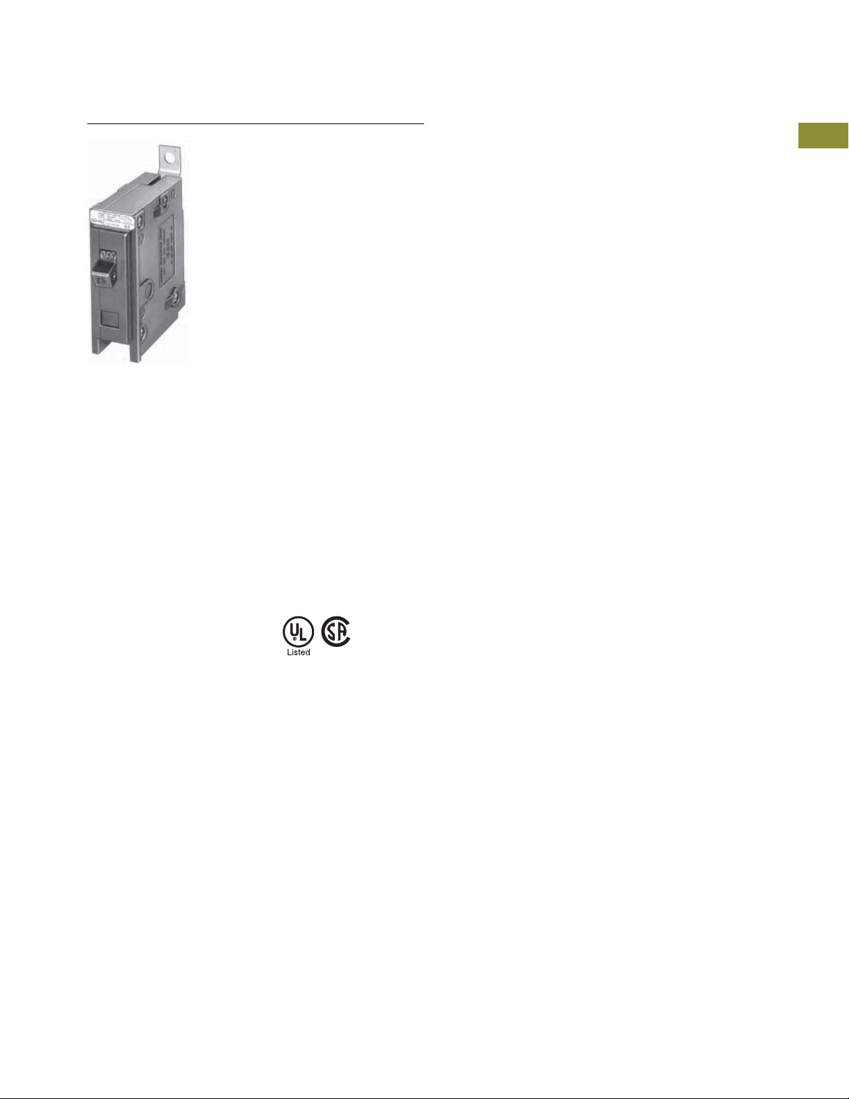
QUICKLAG Type HQP Single-Pole
Industrial Circuit Breakers
1.1
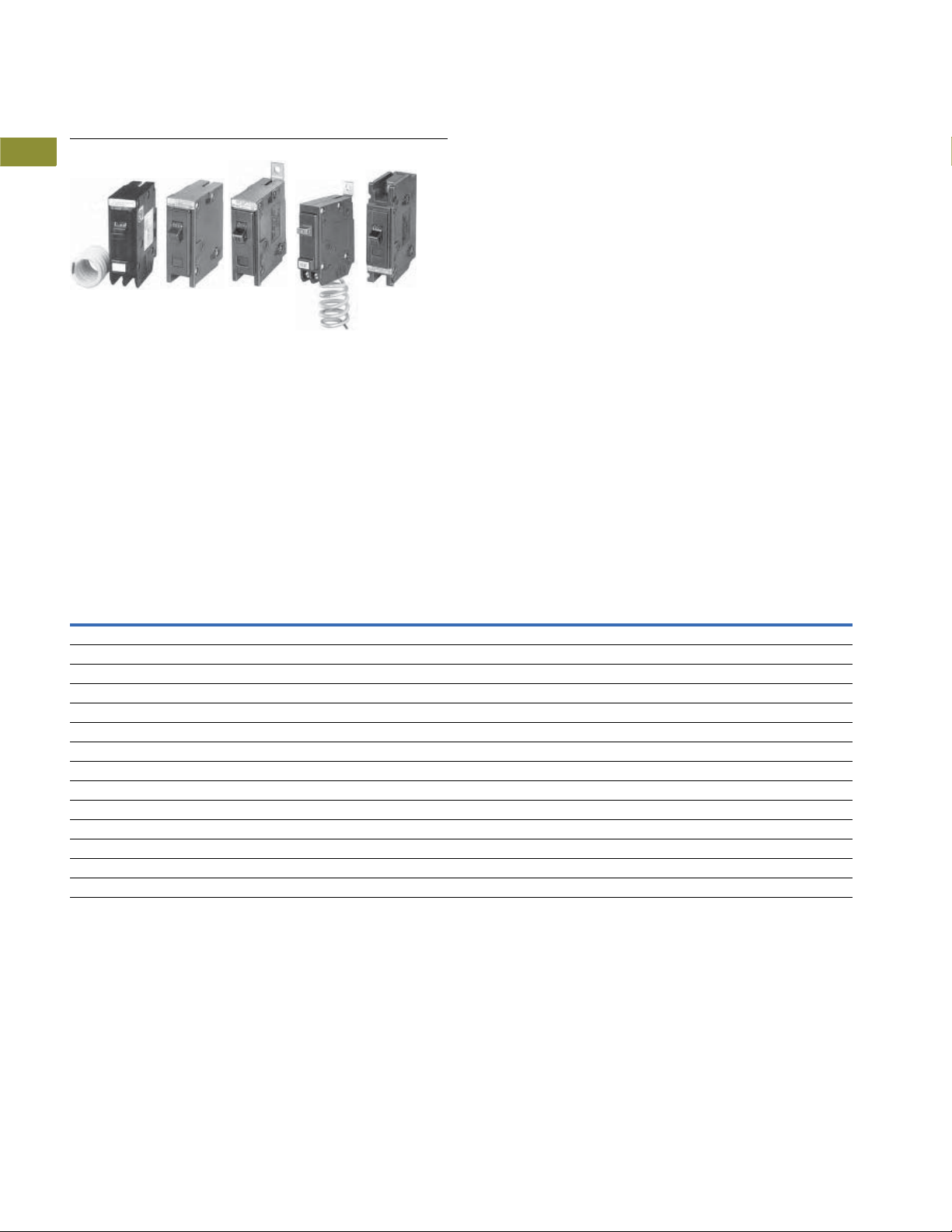
QUICKLAG Plug-On Types HQP, QPHW, QHPX, QHPW
Product Description
●
All products 15–100A are
HACR rated
●
Switching duty rated for
120 Vac fluorescent light
applications
Standards and Certifications
●
Built and listed to UL 489
●
All products UL and
®
listed
CSA
Contents
Description Page
Quick Reference . . . . . . . . . . . . . . . . . . . . . . . . . . . . . V4-T1-2
QUICKLAG Plug-On Types HQP, QPHW, QHPX, QHPW
Product Selection. . . . . . . . . . . . . . . . . . . . . . . .
Dimensions . . . . . . . . . . . . . . . . . . . . . . . . . . . . V4-T1-7
QUICKLAG Plug-On Ground Fault and Equipment Protectors,
Types QPGFT, QPHGFT, QPGFEP, QPHGFEP . . . . .
Bolt-On Types BAB, QBHW, HBAX, HBAW . . . . . . . . V4-T1-11
Bolt-On Arc Fault Circuit Interrupter Types
QBAF, QBCAF. . . . . . . . . . . . . . . . . . . . . . . . . . . . . .
Bolt-On Ground Fault and Equipment Protectors,
Types QBGFT, QBHGFT, QBGFEP, QBHGFEP . . . . .
Cable-In/Cable-Out Types QC, QCD, QCHW,
QHCX, QHCW . . . . . . . . . . . . . . . . . . . . . . . . . . . . .
Cable-In/Cable-Out, 1/2-Inch Wide, Types QCR, QCF,
QCRH, QCFH . . . . . . . . . . . . . . . . . . . . . . . . . . . . . .
Cable-In/Cable-Out Ground Fault and Equipment Protectors,
Types QCGFT, QCHGFT, QCGFEP, QCHGFEP . . . . .
Solenoid-Operated, Remote-Controlled Latching
Types BABRP, BABRSP, BRRP and CLRP. . . . . . . . .
Solenoid Operator—Remote Controlled Latching for
Type GHBS, GBHS and GHQRSP Breakers. . . . . . .
International Rated Types HQP, BA, QC, GFMB, GFXBC V4-T1-36
Special Application Breakers, Types HQP, BA, QC . . . V4-T1-39
V4-T1-6
V4-T1-8
V4-T1-14
V4-T1-16
V4-T1-19
V4-T1-23
V4-T1-27
V4-T1-30
V4-T1-33
1
1
1
1
1
1
1
1
1
1
1
1
1
1
1
1
1
1
1
1
1
1
1
1
1
1
1
1
1
1
Volume 4—Circuit Protection CA08100005E—April 2019 V4-T1-5
1.1
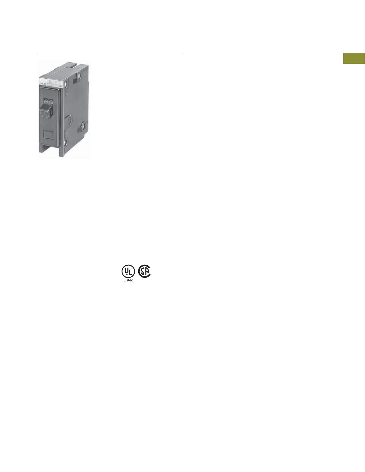
QUICKLAG Type HQP
Single-Pole
Product Selection
1
Miniature Circuit Breakers and Supplementary Protectors
Industrial Circuit Breakers
1
1
1
1
1
1
1
1
1
1
1
1
1
1
1
1
QUICKLAG Type: HQP 10,000A Interrupting Capacity Thermal-Magnetic Breakers
Continuous
Ampere Rating
at 40°C
10 HQP1010 HQP2010 — HQP3010H
15 HQP1015
20 HQP1020
25 HQP1025 HQP2025 HQP2025H HQP3025H
30 HQP1030 HQP2030 HQP2030H HQP3030H
35 HQP1035 HQP2035 HQP2035H HQP3035H
40 HQP1040 HQP2040 HQP2040H HQP3040H
45 HQP1045 HQP2045 HQP2045H HQP3045H
50 HQP1050 HQP2050 HQP2050H HQP3050H
55 HQP1055 HQP2055 HQP2055H HQP3055H
60 HQP1060 HQP2060 HQP2060H HQP3060H
70 HQP1070 HQP2070 HQP2070H HQP3070H
80 — HQP2080 HQP2080H HQP3080H
90 — HQP2090 HQP2090H HQP3090H
100 HQP1100 HQP2100 HQP2100H HQP3100H
110 — HQP2110 — —
125 — HQP2125 — —
150 — HQP2150 — —
QUICKLAG Type: HQP Non-Automatic Switches
Continuous
Ampere Rating
at 40°C
50 HQP1050N — HQP2050N HQP3050N
60 HQP1060N — HQP2060N HQP3060N
100 HQP1100N — HQP2100N HQP3100N
Single-Pole Two-Pole Two-Pole Three-Pole
120/240 Vac 120/240 Vac 240 Vac 240 Vac
Catalog Number Catalog Number Catalog Number Catalog Number
12
12
Single-Pole Two-Pole Two-Pole Three-Pole
120/240 Vac 120/240 Vac 240 Vac 240 Vac
Catalog Number Catalog Number Catalog Number Catalog Number
HQP2015 HQP2015H HQP3015H
HQP2020 HQP2020H HQP3020H
3
1
1
1
1
1
1
1
1
1
1
1
1
1
QUICKLAG Type: QPHW 22,000A Interrupting Capacity Thermal-Magnetic Breakers
Continuous
Ampere Rating
at 40°C
15 QPHW1015
20 QPHW1020
25 QPHW1025 QPHW2025 QPHW2025H QPHW3025H
30 QPHW1030 QPHW2030 QPHW2030H QPHW3030H
35 QPHW1035 QPHW2035 QPHW2035H QPHW3035H
40 QPHW1040 QPHW2040 QPHW2040H QPHW3040H
45 QPHW1045 QPHW2045 QPHW2045H QPHW3045H
50 QPHW1050 QPHW2050 QPHW2050H QPHW3050H
55 QPHW1055 QPHW2055 QPHW2055H QPHW3055H
60 QPHW1060 QPHW2060 QPHW2060H QPHW3060H
70 QPHW1070 QPHW2070 QPHW2070H QPHW3070H
80 — QPHW2080 QPHW2080H QPHW3080H
90 — QPHW2090 QPHW2090H QPHW3090H
100 — QPHW2100 QPHW2100H QPHW3100H
110 — QPHW2110 — —
125 — QPHW2125 — —
Notes
1
Switching duty rated for 120 Vac fluorescent light applications.
2
For special low-magnetic breaker, order HQP1015L1 or HQP1020L1.
3
Not UL listed.
Single-Pole Two-Pole Two-Pole Three-Pole
120/240 Vac 120/240 Vac 240 Vac 240 Vac
Catalog Number Catalog Number Catalog Number Catalog Number
1
1
QPHW2015 QPHW2015H QPHW3015H
QPHW2020 QPHW2020H QPHW3020H
V4-T1-6 Volume 4—Circuit Protection CA08100005E—April 2019

Miniature Circuit Breakers and Supplementary Protectors
Industrial Circuit Breakers
1.1
QUICKLAG Type: QHPX 42,000A Interrupting Capacity Thermal-Magnetic Breakers
Continuous
Ampere Rating
at 40°C
15 QHPX1015
20 QHPX1020
25 QHPX1025 QHPX2025 — QHPX3025H
30 QHPX1030 QHPX2030 — QHPX3030H
35 QHPX1035 QHPX2035 — QHPX3035H
40 QHPX1040 QHPX2040 — QHPX3040H
45 QHPX1045 QHPX2045 — QHPX3045H
50 QHPX1050 QHPX2050 — QHPX3050H
55 QHPX1055 QHPX2055 — QHPX3055H
60 QHPX1060 QHPX2060 — QHPX3060H
70 QHPX1070 QHPX2070 — QHPX3070H
80 — QHPX2080 — QHPX3080H
90 — QHPX2090 — QHPX3090H
100 — QHPX2100 — QHPX3100H
QUICKLAG Type: QHPW 65,000A Interrupting Capacity Thermal-Magnetic Breakers
Continuous
Ampere Rating
at 40°C
15 QHPW1015
20 QHPW1020
25 QHPW1025QHPW2025— —
30 QHPW1030QHPW2030— —
Single-Pole Two-Pole Two-Pole Three-Pole
120/240 Vac 120/240 Vac 240 Vac 240 Vac
Catalog Number Catalog Number Catalog Number Catalog Number
1
1
Single-Pole Two-Pole Two-Pole Three-Pole
120/240 Vac 120/240 Vac 240 Vac 240 Vac
Catalog Number Catalog Number Catalog Number Catalog Number
1
1
QHPX2015 — QHPX3015H
QHPX2020 — QHPX3020H
QHPW2015 — QHPW3015H
QHPW2020 — QHPW3020H
1
1
1
1
1
1
1
1
1
1
1
1
1
1
1
Dimensions
Approximate Dimensions in Inches (mm)
Shipping Data
Number
of Poles
1 24 9.00 (4.1) 12.50 x 7.50 x 5.00 (317.5 x 190.5 x 127.0)
2 12 9.00 (4.1) 12.50 x 7.50 x 5.00 (317.5 x 190.5 x 127.0)
3 8 9.00 (4.1) 12.50 x 7.50 x 5.00 (317.5 x 190.5 x 127.0)
Note
1
Switching duty rated for 120 Vac fluorescent light applications.
Carton
Quantity
Approximate
Weight Lbs (kg) Dimensions
1
1
1
1
1
1
1
1
1
1
1
1
1
1
Volume 4—Circuit Protection CA08100005E—April 2019 V4-T1-7
1
1.1
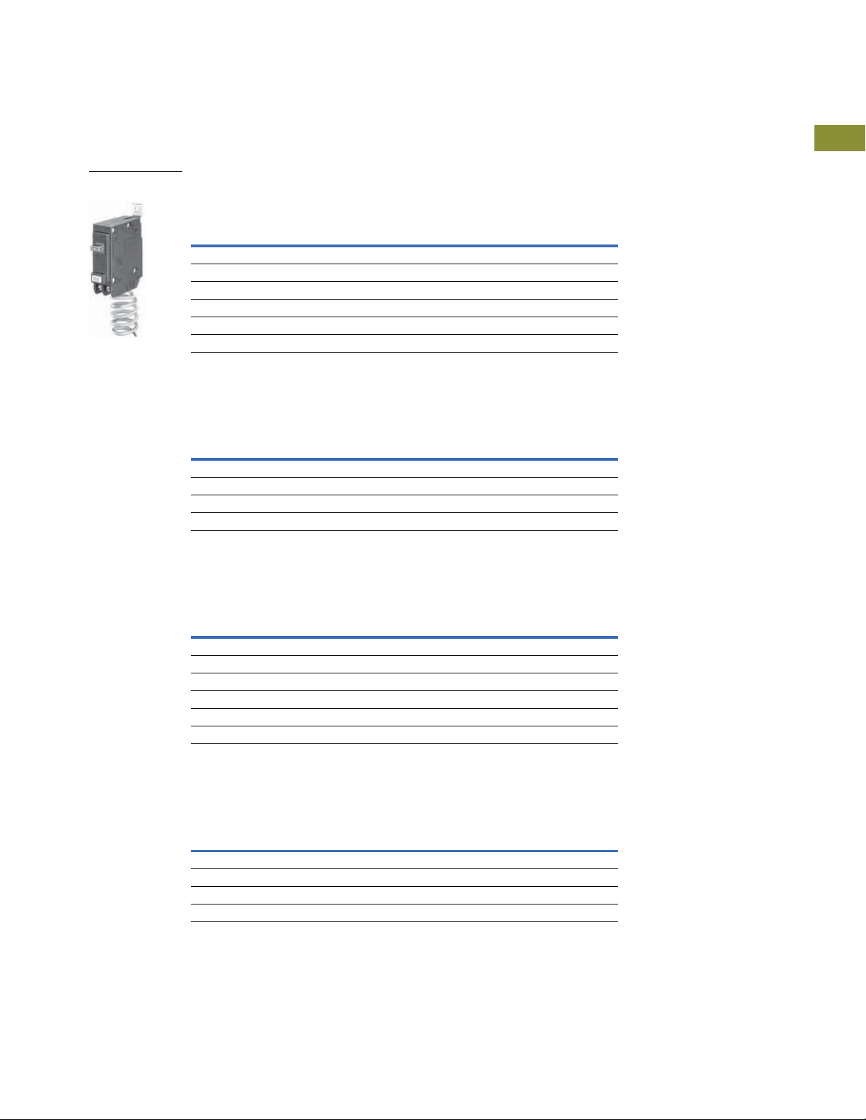
QUICKLAG Type QPGFT Single-Pole
Ground Fault Circuit Breaker
Miniature Circuit Breakers and Supplementary Protectors
Industrial Circuit Breakers
1
1
1
1
1
1
1
1
1
1
1
1
1
QUICKLAG Plug-On Ground Fault and Equipment
1
Protectors, Types QPGFT, QPHGFT, QPGFEP, QPHGFEP
1
Product Description
1
QUICKLAG Ground Fault Circuit
Breakers, Class A GFCI
●
1
1
1
5 mA trip sensitivity
QUICKLAG Ground Fault
Equipment Protectors
●
30 mA trip sensitivity
Standards and Certifications
●
Built and listed to UL 489
QUICKLAG Ground Fault Circuit
Breakers, Class A GFCI
●
Built and tested to UL 943
QUICKLAG Ground Fault
Equipment Protectors
●
Built and listed to UL 1053
1
Contents
Description Page
Quick Reference. . . . . . . . . . . . . . . . . . . . . . . . . . . . . . V4-T1-2
QUICKLAG Plug-On Types HQP, QPHW, QHPX, QHPW V4-T1-5
QUICKLAG Plug-On Ground Fault and Equipment Protectors,
Types QPGFT, QPHGFT, QPGFEP, QPHGFEP
Product Selection . . . . . . . . . . . . . . . . . . . . . . . .
Wiring Diagram . . . . . . . . . . . . . . . . . . . . . . . . . . V4-T1-10
Dimensions . . . . . . . . . . . . . . . . . . . . . . . . . . . . . V4-T1-10
Bolt-On Types BAB, QBHW, HBAX, HBAW . . . . . . . . V4-T1-11
Bolt-On Arc Fault Circuit Interrupter Types
QBAF, QBCAF . . . . . . . . . . . . . . . . . . . . . . . . . . . . . .
Bolt-On Ground Fault and Equipment Protectors,
Types QBGFT, QBHGFT, QBGFEP, QBHGFEP . . . . .
Cable-In/Cable-Out Types QC, QCD, QCHW,
QHCX, QHCW. . . . . . . . . . . . . . . . . . . . . . . . . . . . . .
Cable-In/Cable-Out, 1/2-Inch Wide, Types QCR, QCF,
QCRH, QCFH . . . . . . . . . . . . . . . . . . . . . . . . . . . . . .
Cable-In/Cable-Out Ground Fault and Equipment Protectors,
Types QCGFT, QCHGFT, QCGFEP, QCHGFEP . . . . .
Solenoid-Operated, Remote-Controlled Latching
Types BABRP, BABRSP, BRRP and CLRP. . . . . . . . .
Solenoid Operator—Remote Controlled Latching for
Type GHBS, GBHS and GHQRSP Breakers . . . . . . .
International Rated Types HQP, BA, QC, GFMB, GFXBC V4-T1-36
Special Application Breakers, Types HQP, BA, QC . . . V4-T1-39
V4-T1-9
V4-T1-14
V4-T1-16
V4-T1-19
V4-T1-23
V4-T1-27
V4-T1-30
V4-T1-33
1
1
1
1
1
1
1
1
1
1
V4-T1-8 Volume 4—Circuit Protection CA08100005E—April 2019

Miniature Circuit Breakers and Supplementary Protectors
QUICKLAG Type QPGFT
Single-Pole
Industrial Circuit Breakers
1.1
Product Selection
Ground Fault Circuit Breakers—5 mA Sensitivity QUICKLAG Type:
QPGFT 10,000A Interrupting Capacity Thermal-Magnetic Breakers
Continuous
Ampere Rating
at 40°C
15 QPGFT1015 QPGFT2015
20 QPGFT1020 QPGFT2020
25 QPGFT1025 QPGFT2025
30 QPGFT1030 QPGFT2030
40 QPGFT1040 QPGFT2040
50 — QPGFT2050
Ground Fault Circuit Breakers—5 mA Sensitivity QUICKLAG Type:
QPHGF 22,000A Interrupting Capacity Thermal-Magnetic Breakers
Continuous
Ampere Rating
at 40°C
15 QPHGF1015 QPHGF2015
20 QPHGF1020 QPHGF2020
25 QPHGF1025 QPHGF2025
30 QPHGF1030 QPHGF2030
Single-Pole Two-Pole
120 Vac 120/240 Vac
Catalog Number Catalog Number
Single-Pole Two-Pole
120 Vac 120/240 Vac
Catalog Number Catalog Number
1
1
1
1
1
1
1
1
1
1
1
1
1
1
Ground Fault Equipment Breakers—30 mA Sensitivity QUICKLAG Type:
QPGFEP 10,000 Interrupting Capacity Thermal-Magnetic Breakers
Continuous
Ampere Rating
at 40°C
15 QPGFEP1015 QPGFEP2015
20 QPGFEP1020 QPGFEP2020
25 QPGFEP1025 QPGFEP2025
30 QPGFEP1030 QPGFEP2030
40 QPGFEP1040 QPGFEP2040
50 — QPGFEP2050
Ground Fault Equipment Breakers—30 mA Sensitivity QUICKLAG Type:
QPHGFEP 22,000A Interrupting Capacity Thermal-Magnetic Breakers
Continuous
Ampere Rating
at 40°C
15 QPHGFEP1015 QPHGFEP2015
20 QPHGFEP1020 QPHGFEP2020
25 QPHGFEP1025 QPHGFEP2025
30 QPHGFEP1030 QPHGFEP2030
Single-Pole Two-Pole
120 Vac 120/240 Vac
Catalog Number Catalog Number
Single-Pole Two-Pole
120 Vac 120/240 Vac
Catalog Number Catalog Number
1
1
1
1
1
1
1
1
1
1
1
1
1
1
Volume 4—Circuit Protection CA08100005E—April 2019 V4-T1-9
1
1

Miniature Circuit Breakers and Supplementary Protectors
Blue Wire
Red Wire
Black Wire
Ground
Fault
Breaker
Single-throw double-pole contacts are UL and CSA listed for 5A at 250 Vac.
Bell Alarm (W1)—contacts change state when breaker trips.
Auxiliary Switch (W2)—contacts change state when breaker is opened (or tripped) or closed.
14-inch (355.6 mm) long 18 AWG pigtail wire leads provided.
Blue
Red
NC
NO
1.1
Special Application Ground Fault Circuit Protectors—5 mA Sensitivity
1
QUICKLAG Type: QPGFT 10,000A Interrupting Capacity with Bell Alarm (W1) or
Auxiliary Switch (W2)
1
Continuous
Ampere Rating
1
at 40°C
15 QPGFT1015W1 QPGFT2015W1
1
20 QPGFT1020W1 QPGFT2020W1
25 QPGFT1025W1 QPGFT2025W1
1
30 QPGFT1030W1 QPGFT2030W1
40 — QPGFT2040W1
1
50 — QPGFT2050W1
15 QPGFT1015W2 —
1
20 QPGFT1020W2 —
25 QPGFT1025W2 —
1
30 QPGFT1030W2 —
1
Special Application Ground Fault Circuit Protectors—30 mA Sensitivity
QUICKLAG Type: QPGFEP 10,000A Interrupting Capacity with Bell Alarm (W1) or
1
Auxiliary Switch (W2)
1
Continuous
Ampere Rating
at 40°C
1
15 QPGFEP1015W1 QPGFEP2 015W1
1
20 QPGFEP1020W1 QPGFEP2 020W1
25 QPGFEP1025W1 QPGFEP2 025W1
1
30 QPGFEP1030W1 QPGFEP2 030W1
40
1
50
15 QPGFEP1015W2 —
1
20 QPGFEP1020W2 —
25 QPGFEP1025W2 —
1
30 QPGFEP1030W2 —
1
Industrial Circuit Breakers
Single-Pole Two-Pole
120 Vac 120/240 Vac
Catalog Number Catalog Number
Single-Pole Two-Pole
120 Vac 120/240 Vac
Catalog Number Catalog Number
—
—
QPGFEP2040W1
QPGFEP2050W1
Wiring Diagram
1
Bell Alarm and Auxiliary Contact Schematic
1
1
1
1
1
1
Dimensions
Approximate Dimensions in Inches (mm)
1
Shipping Data
1
Number
of Poles
1
1 24 11.00 (5.0) 12.50 x 6.50 x 5.00 (317.5 x 165.1 x 127.0)
2 5 5.00 (2.3) 15.50 x 6.00 x 4.50 (393.7 x 152.4 x 114.3)
1
Note
Shipped individually or in carton quantities.
1
V4-T1-10 Volume 4—Circuit Protection CA08100005E—April 2019
Carton
Quantity
Approximate
Weight Lbs (kg) Dimensions
Miniature Circuit Breakers and Supplementary Protectors
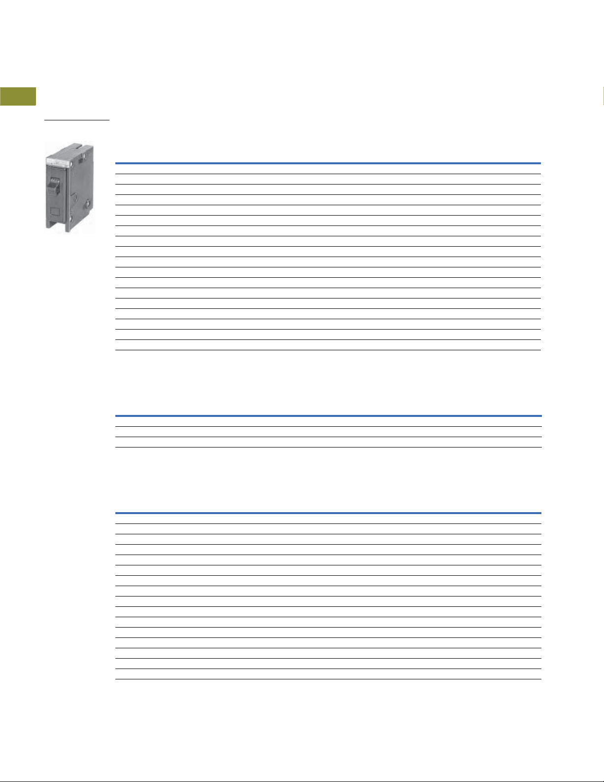
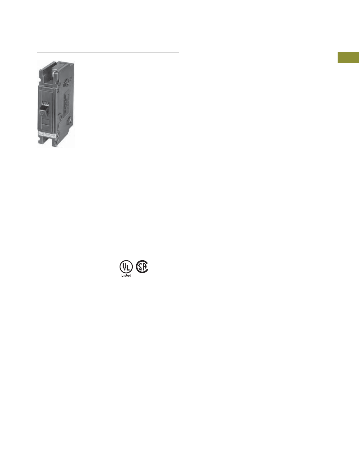
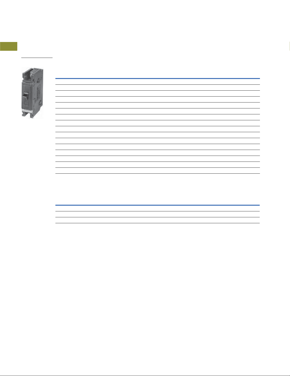
QUICKLAG Type BAB Single-Pole
Industrial Circuit Breakers
1.1
Bolt-On Types BAB, QBHW, HBAX, HBAW
Product Description
●
All products 15–100A are
HACR rated
●
Switching duty rated
for 120 Vac fluorescent
light applications
Standards and Certifications
●
Built and listed to UL 489
●
All products UL and
CSA listed
Contents
Description Page
Quick Reference . . . . . . . . . . . . . . . . . . . . . . . . . . . . . V4-T1-2
QUICKLAG Plug-On Types HQP, QPHW, QHPX, QHPW V4-T1-5
QUICKLAG Plug-On Ground Fault and Equipment Protectors,
Types QPGFT, QPHGFT, QPGFEP, QPHGFEP . . . . .
Bolt-On Types BAB, QBHW, HBAX, HBAW
Product Selection. . . . . . . . . . . . . . . . . . . . . . . .
Dimensions . . . . . . . . . . . . . . . . . . . . . . . . . . . . V4-T1-13
Bolt-On Arc Fault Circuit Interrupter Types
QBAF, QBCAF. . . . . . . . . . . . . . . . . . . . . . . . . . . . . .
Bolt-On Ground Fault and Equipment Protectors,
Types QBGFT, QBHGFT, QBGFEP, QBHGFEP . . . . .
Cable-In/Cable-Out Types QC, QCD, QCHW,
QHCX, QHCW . . . . . . . . . . . . . . . . . . . . . . . . . . . . .
Cable-In/Cable-Out, 1/2-Inch Wide, Types QCR, QCF,
QCRH, QCFH . . . . . . . . . . . . . . . . . . . . . . . . . . . . . .
Cable-In/Cable-Out Ground Fault and Equipment Protectors,
Types QCGFT, QCHGFT, QCGFEP, QCHGFEP . . . . .
Solenoid-Operated, Remote-Controlled Latching
Types BABRP, BABRSP, BRRP and CLRP. . . . . . . . .
Solenoid Operator—Remote Controlled Latching for
Type GHBS, GBHS and GHQRSP Breakers. . . . . . .
International Rated Types HQP, BA, QC, GFMB, GFXBC V4-T1-36
Special Application Breakers, Types HQP, BA, QC . . . V4-T1-39
V4-T1-8
V4-T1-12
V4-T1-14
V4-T1-16
V4-T1-19
V4-T1-23
V4-T1-27
V4-T1-30
V4-T1-33
1
1
1
1
1
1
1
1
1
1
1
1
1
1
1
1
1
1
1
1
1
1
1
1
1
1
1
1
1
1
Volume 4—Circuit Protection CA08100005E—April 2019 V4-T1-11
1.1
QUICKLAG Type BAB
Single-Pole
Product Selection
1
Miniature Circuit Breakers and Supplementary Protectors
Industrial Circuit Breakers
1
1
1
1
1
1
1
1
1
1
1
1
1
1
1
1
QUICKLAG Type: BA 10,000A Interrupting Capacity Thermal-Magnetic Breakers
Continuous
Ampere Rating
at 40°C
10 BAB1010 BAB2010 BAB2010H
15 BAB1015
20 BAB1020
25 BAB1025 BAB2025 BAB2025H BAB3025H
30 BAB1030 BAB2030 BAB2030H BAB3030H
35 BAB1035 BAB2035 BAB2035H BAB3035H
40 BAB1040 BAB2040 BAB2040H BAB3040H
45 BAB1045 BAB2045 BAB2045H BAB3045H
50 BAB1050 BAB2050 BAB2050H BAB3050H
55 BAB1055 BAB2055 BAB2055H BAB3055H
60 BAB1060 BAB2060 BAB2060H BAB3060H
70 BAB1070 BAB2070 BAB2070H BAB3070H
80 — BAB2080 BAB2080H BAB3080H
90 — BAB2090 BAB2090H BAB3090H
100 BAB1100 BAB2100 BAB2100H BAB3100H
110 — BAB2110 — —
125 — BAB2125 — —
QUICKLAG Type: BA Non-Automatic Switches
Continuous
Ampere Rating
at 40°C
50 BAB1050N — BAB2050N BAB3050N
60 BAB1060N — BAB2060N BAB3060N
100 BAB1100N — BAB2100N BAB3100N
Single-Pole Two-Pole Two-Pole Three-Pole
120/240 Vac 120/240 Vac 240 Vac 240 Vac
Catalog Number Catalog Number Catalog Number Catalog Number
3
12
12
Single-Pole Two-Pole Two-Pole Three-Pole
120/240 Vac 120/240 Vac 240 Vac 240 Vac
Catalog Number Catalog Number Catalog Number Catalog Number
BAB2015 BAB2015H BAB3015H
BAB2020 BAB2020H BAB3020H
BAB3010H
3
1
1
1
1
1
1
1
1
1
1
1
1
1
QUICKLAG Type: QBHW 22,000A Interrupting Capacity Thermal-Magnetic Breakers
Continuous
Ampere Rating
at 40°C
15 QBHW1015
20 QBHW1020
25 QBHW1025 QBHW2025 QBHW2025H QBHW3025H
30 QBHW1030 QBHW2030 QBHW2030H QBHW3030H
35 QBHW1035 QBHW2035 QBHW2035H QBHW3035H
40 QBHW1040 QBHW2040 QBHW2040H QBHW3040H
45 QBHW1045 QBHW2045 QBHW2045H QBHW3045H
50 QBHW1050 QBHW2050 QBHW2050H QBHW3050H
55 QBHW1055 QBHW2055 QBHW2055H QBHW3055H
60 QBHW1060 QBHW2060 QBHW2060H QBHW3060H
70 QBHW1070 QBHW2070 QBHW2070H QBHW3070H
80 — QBHW2080 QBHW2080H QBHW3080H
90 — QBHW2090 QBHW2090H QBHW3090H
100 — QBHW2100 QBHW2100H QBHW3100H
110 — QBHW2110 — —
125 — QBHW2125 — —
Notes
1
Switching duty rated for 120 Vac fluorescent light applications.
2
For special low-magnetic breaker, order BAB1015L1 or BAB1020L1.
3
Not UL listed.
Single-Pole Two-Pole Two-Pole Three-Pole
120/240 Vac 120/240 Vac 240 Vac 240 Vac
Catalog Number Catalog Number Catalog Number Catalog Number
1
1
QBHW2015 QBHW2015H QBHW3015H
QBHW2020 QBHW2020H QBHW3020H
V4-T1-12 Volume 4—Circuit Protection CA08100005E—April 2019

Miniature Circuit Breakers and Supplementary Protectors
Industrial Circuit Breakers
1.1
QUICKLAG Type: HBAX 42,000A Interrupting Capacity Thermal-Magnetic Breakers
Continuous
Ampere Rating
at 40°C
15 HBAX1015
20 HBAX1020
25 HBAX1025 HBAX2025 — HBAX3025H
30 HBAX1030 HBAX2030 — HBAX3030H
35 HBAX1035 HBAX2035 — HBAX3035H
40 HBAX1040 HBAX2040 — HBAX3040H
45 HBAX1045 HBAX2045 — HBAX3045H
50 HBAX1050 HBAX2050 — HBAX3050H
55 HBAX1055 HBAX2055 — HBAX3055H
60 HBAX1060 HBAX2060 — HBAX3060H
70 HBAX1070 HBAX2070 — HBAX3070H
80 — HBAX2080 — HBAX3080H
80 — HBAX2080 — HBAX3080H
90 — HBAX2090 — HBAX3090H
100 — HBAX2100 — HBAX3100H
QUICKLAG Type: HBAW 65,000A Interrupting Capacity Thermal-Magnetic Breakers
Continuous
Ampere Rating
at 40°C
15 HBAW1015
20 HBAW1020
25 HBAW1025 HBAW2025 — —
30 HBAW1030 HBAW2030 — —
Single-Pole Two-Pole Two-Pole Three-Pole
120/240 Vac 120/240 Vac 240 Vac 240 Vac
Catalog Number Catalog Number Catalog Number Catalog Number
1
1
Single-Pole Two-Pole Two-Pole Three-Pole
120/240 Vac 120/240 Vac 240 Vac 240 Vac
Catalog Number Catalog Number Catalog Number Catalog Number
1
1
HBAX2015 — HBAX3015H
HBAX2020 — HBAX3020H
HBAW2015 — HBAW3015H
HBAW2020 — HBAW3020H
1
1
1
1
1
1
1
1
1
1
1
1
1
1
1
1
1
Dimensions
Approximate Dimensions in Inches (mm)
Shipping Data
Number
of Poles
1 24 9.00 (4.1) 12.50 x 7.50 x 5.00 (317.5 x 190.5 x 127.0)
2 12 9.00 (4.1) 12.50 x 7.50 x 5.00 (317.5 x 190.5 x 127.0)
3 8 9.00 (4.1) 12.50 x 7.50 x 5.00 (317.5 x 190.5 x 127.0)
Note
1
Switching duty rated for 120 Vac fluorescent light applications.
Carton
Quantity
Approximate
Weight Lbs (kg) Dimensions
1
1
1
1
1
1
1
1
1
1
1
1
1
Volume 4—Circuit Protection CA08100005E—April 2019 V4-T1-13
1.1
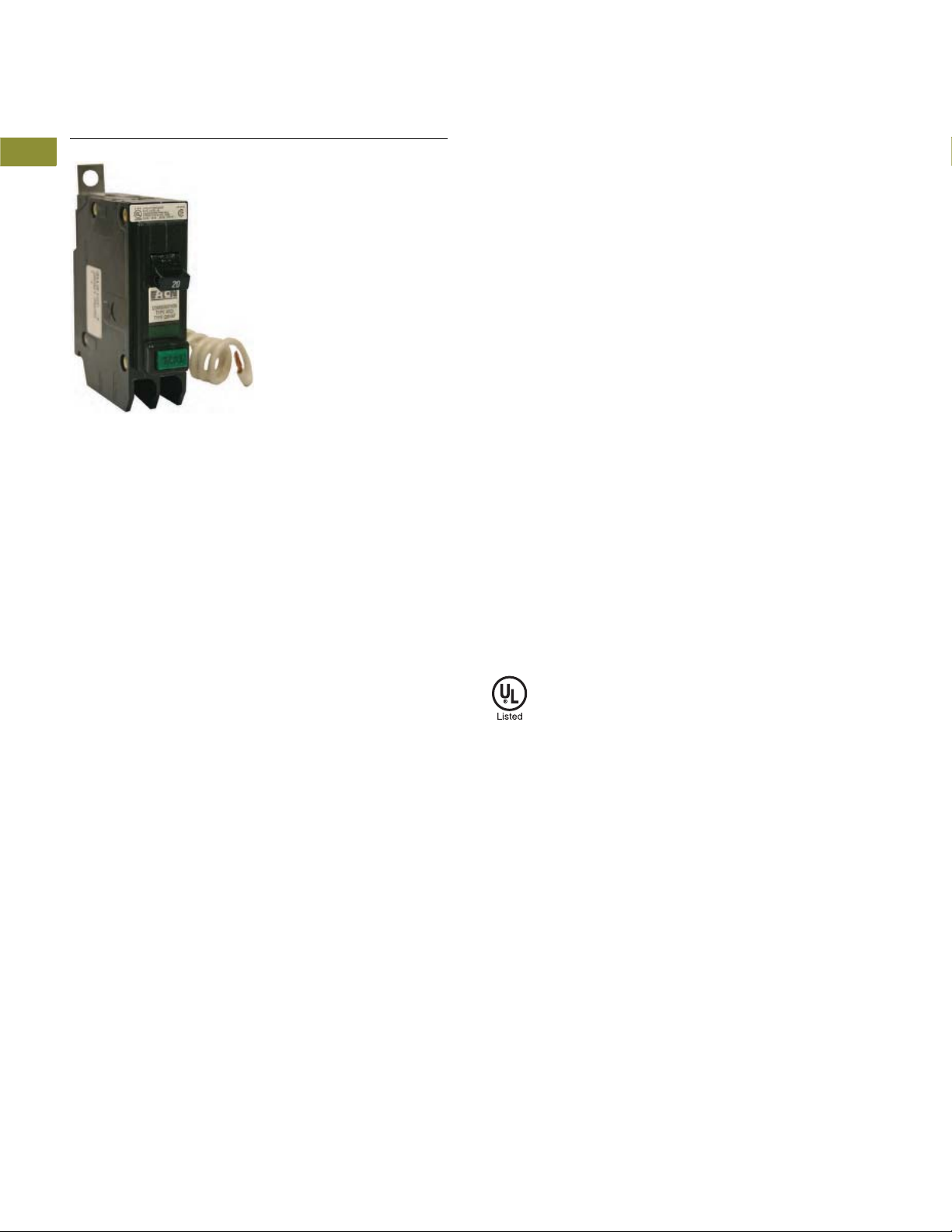
Bolt-On Arc Fault Circuit Interrupter QUICKLAG Types QBAF, QBCAF
Miniature Circuit Breakers and Supplementary Protectors
Industrial Circuit Breakers
1
1
1
1
1
1
1
1
1
1
1
1
1
Bolt-On Arc Fault Circuit Interrupter Types QBAF, QBCAF
1
Product Description
1
●
All products HACR rated
1
1
1
Features, Benefits and
Functions
●
10 and 22 kAIC rating at
120V and 120/240V
●
Single-pole AFCI
●
HID ratings for HID (High
Intensity Discharge) lighting
●
All models are HACR rated
1
Contents
Description Page
Quick Reference. . . . . . . . . . . . . . . . . . . . . . . . . . . . . . V4-T1-2
QUICKLAG Plug-On Types HQP, QPHW, QHPX, QHPW V4-T1-5
QUICKLAG Plug-On Ground Fault and Equipment Protectors,
Types QPGFT, QPHGFT, QPGFEP, QPHGFEP . . . . .
Bolt-On Types BAB, QBHW, HBAX, HBAW . . . . . . . . V4-T1-11
Bolt-On Arc Fault Circuit Interrupter Types
QBAF, QBCAF
Product Selection . . . . . . . . . . . . . . . . . . . . . . . .
Wiring Diagrams . . . . . . . . . . . . . . . . . . . . . . . . . V4-T1-15
Bolt-On Ground Fault and Equipment Protectors,
Types QBGFT, QBHGFT, QBGFEP, QBHGFEP . . . . .
Cable-In/Cable-Out Types QC, QCD, QCHW,
QHCX, QHCW. . . . . . . . . . . . . . . . . . . . . . . . . . . . . .
Cable-In/Cable-Out, 1/2-Inch Wide, Types QCR, QCF,
QCRH, QCFH . . . . . . . . . . . . . . . . . . . . . . . . . . . . . .
Cable-In/Cable-Out Ground Fault and Equipment Protectors,
Types QCGFT, QCHGFT, QCGFEP, QCHGFEP . . . . .
Solenoid-Operated, Remote-Controlled Latching
Types BABRP, BABRSP, BRRP and CLRP. . . . . . . . .
Solenoid Operator—Remote Controlled Latching for
Type GHBS, GBHS and GHQRSP Breakers . . . . . . .
International Rated Types HQP, BA, QC, GFMB, GFXBC V4-T1-36
Special Application Breakers, Types HQP, BA, QC . . . V4-T1-39
Standards and Certifications
●
Built and listed to UL 489
●
UL File E7819 for QBAF
V4-T1-8
V4-T1-15
V4-T1-16
V4-T1-19
V4-T1-23
V4-T1-27
V4-T1-30
V4-T1-33
1
1
1
1
1
1
1
1
1
1
1
V4-T1-14 Volume 4—Circuit Protection CA08100005E—April 2019

Miniature Circuit Breakers and Supplementary Protectors
QBHCAF
NAB
120/240 Vac
Source
120V
Duplex
Receptacle
Single-Pole
Line B
Neutral
Neutral
Equipment Ground
Industrial Circuit Breakers
1.1
Product Selection
QBCAF and QBAF Type AFCIs
Effective immediately, Eaton
AFCIs are available for use in
Sumter panels with a 22 kAIC
rating. This higher rated
breaker will allow us to
win jobs where AFCIs are
specified at higher than
10 kAIC. This breaker
provides standard thermal-
1-Inch (25.4 mm) Wide Bolt-On Arc Fault Circuit Interrupter
Poles
Type QBCAF Combination AFCI
Single-pole 10 kAIC 15 Combination AFCI QB1015CAF
Wiring Diagrams
Single-Pole 120V Load Application Single-Pole Shared Neutral with
Sourced by 120/240 Vac Multi-Duplex Receptacle Application
magnetic protection of
branch circuits. This product
will have the same form, fit
and function of the current
bolt-on AFCI (QBCAF and
QBAF Type). Product scope is
below. These breakers are in
Bid Manager™ for Pow-RLine 1a, Pow-R-Line 1a-LX,
kAIC
Rating
22 kAIC 15 Combination AFCI QBH1015CAF
Ampere
Rating Configuration Catalog Number
20 Combination AFCI QB1020CAF
20 Combination AFCI QBH1020CAF
Pow-R-Line 3a and Pow-RLine 4a panelboards. For
series rated combinations,
continue to use the less
expensive 10 kAIC QBCAF
and QBAF offerings.
Breakers can also be ordered
from Vista.
120/240 Vac
Source
NA B
Line B
1
1
1
1
1
1
1
1
1
1
1
1
1
1
1
1
1
Neutral
Two-Pole
Neutral
Two 120V
Duplex
Receptacles
1
1
1
Line A
Equipment Ground
1
1
1
1
1
1
1
1
1
Volume 4—Circuit Protection CA08100005E—April 2019 V4-T1-15
1
1.1
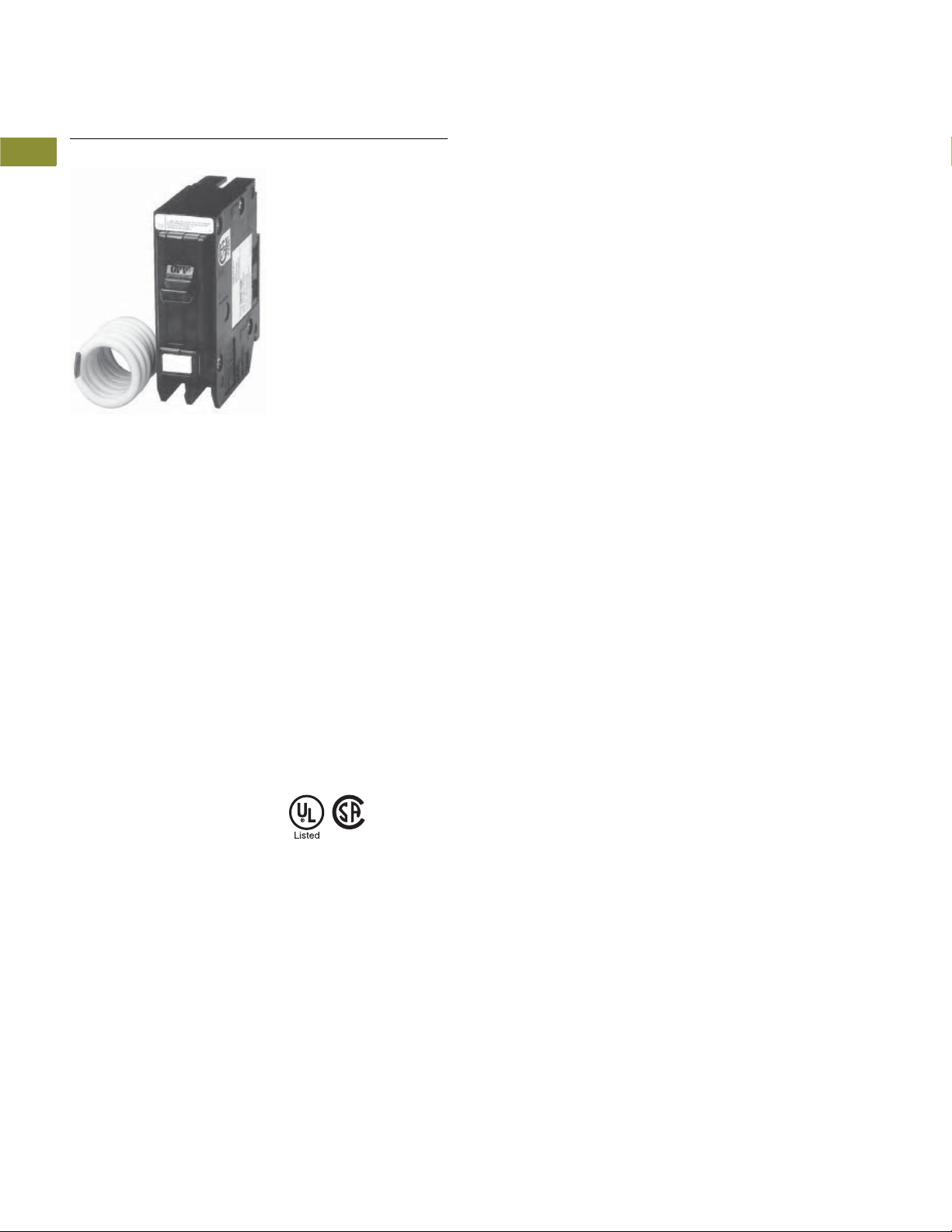
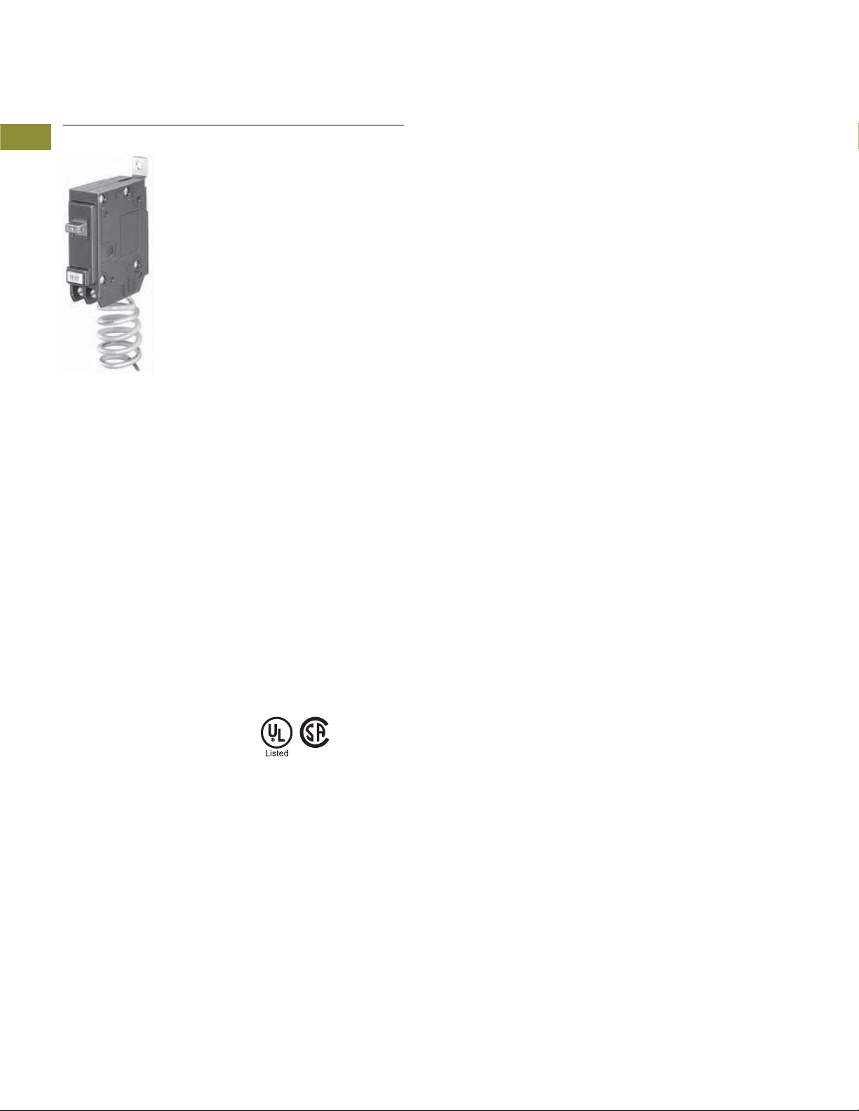
QUICKLAG Type QBGFT Single-Pole
Ground Fault Circuit Breaker
Miniature Circuit Breakers and Supplementary Protectors
Industrial Circuit Breakers
1
1
1
1
1
1
1
1
1
1
1
1
1
Bolt-On Ground Fault and Equipment Protectors,
1
Types QBGFT, QBHGFT, QBGFEP, QBHGFEP
1
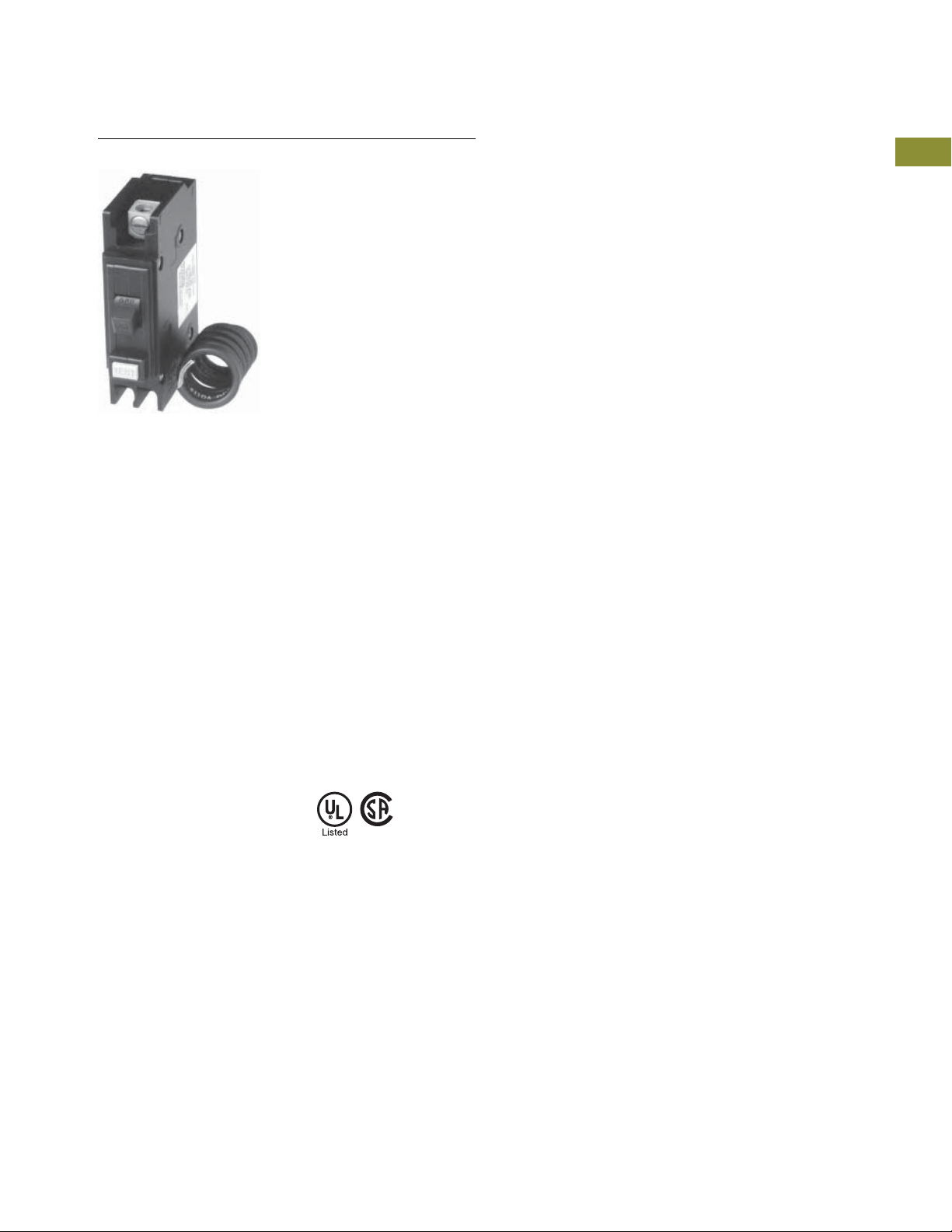
Product Description
1
QUICKLAG Ground Fault Circuit
Breakers, Class A GFCI
●
1
1
1
5 mA trip sensitivity
QUICKLAG Ground Fault
Equipment
Protectors
●
30 mA trip sensitivity
Standards and Certifications
●
Built and tested to UL 489
QUICKLAG Ground Fault Circuit
Breakers, Class A GFCI
●
Built and tested to UL 943
QUICKLAG Ground Fault
Equipment Protectors
●
Built and tested to UL 1053
1
Contents
Description Page
QUICKLAG Plug-On Types HQP, QPHW, QHPX, QHPW V4-T1-5
QUICKLAG Plug-On Ground Fault and Equipment Protectors,
Types QPGFT, QPHGFT, QPGFEP, QPHGFEP . . . . .
Bolt-On Types BAB, QBHW, HBAX, HBAW . . . . . . . . V4-T1-11
Bolt-On Arc Fault Circuit Interrupter Types
QBAF, QBCAF . . . . . . . . . . . . . . . . . . . . . . . . . . . . . .
Bolt-On Ground Fault and Equipment Protectors,
Types QBGFT, QBHGFT, QBGFEP, QBHGFEP
Product Selection . . . . . . . . . . . . . . . . . . . . . . . .
Wiring Diagram . . . . . . . . . . . . . . . . . . . . . . . . . . V4-T1-18
Dimensions . . . . . . . . . . . . . . . . . . . . . . . . . . . . . V4-T1-18
Cable-In/Cable-Out Types QC, QCD, QCHW,
QHCX, QHCW. . . . . . . . . . . . . . . . . . . . . . . . . . . . . .
Cable-In/Cable-Out, 1/2-Inch Wide, Types QCR, QCF,
QCRH, QCFH . . . . . . . . . . . . . . . . . . . . . . . . . . . . . .
Cable-In/Cable-Out Ground Fault and Equipment Protectors,
Types QCGFT, QCHGFT, QCGFEP, QCHGFEP . . . . .
Solenoid-Operated, Remote-Controlled Latching
Types BABRP, BABRSP, BRRP and CLRP. . . . . . . . .
Solenoid Operator—Remote Controlled Latching for
Type GHBS, GBHS and GHQRSP Breakers . . . . . . .
International Rated Types HQP, BA, QC, GFMB, GFXBC V4-T1-36
Special Application Breakers, Types HQP, BA, QC . . . V4-T1-39
V4-T1-8
V4-T1-14
V4-T1-17
V4-T1-19
V4-T1-23
V4-T1-27
V4-T1-30
V4-T1-33
1
1
1
1
1
1
1
1
1
1
V4-T1-16 Volume 4—Circuit Protection CA08100005E—April 2019
Miniature Circuit Breakers and Supplementary Protectors
QUICKLAG Type QBGFT
Single-Pole
Industrial Circuit Breakers
1.1
Product Selection
Ground Fault Circuit Breakers—5 mA Sensitivity QUICKLAG Type:
QBGFT 10,000A Interrupting Capacity Thermal-Magnetic Breakers
Continuous
Ampere Rating
at 40°C
15 QB1015GF QBGFT2015
20 QB1020GF QBGFT2020
25 QB1025GF QBGFT2025
30 QB1030GF QBGFT2030
40 QB1040GF QBGFT2040
50 — QBGFT2050
Ground Fault Circuit Breakers—5 mA Sensitivity QUICKLAG Type:
QBHGFT 22,000A Interrupting Capacity Thermal-Magnetic Breakers
Continuous
Ampere Rating
at 40°C
15 QBH1015GF QBHGF2015
20 QBH1020GF QBHGF2020
25 QBH1025GF QBHGF2025
30 QBH1030GF QBHGF2030
Single-Pole Two-Pole
120 Vac 120/240 Vac
Catalog Number Catalog Number
Single-Pole Two-Pole
120 Vac 120/240 Vac
Catalog Number Catalog Number
1
1
1
1
1
1
1
1
1
1
1
1
1
1
Ground Fault Equipment Breakers—30 mA Sensitivity QUICKLAG Type:
QBGFEP 10,000A Interrupting Capacity Thermal-Magnetic Breakers
Continuous
Ampere Rating
at 40°C
15 QB1015EP QBGFEP2015
20 QB1020EP QBGFEP2020
25 QB1025EP QBGFEP2025
30 QB1030EP QBGFEP2030
40 QB1040EP QBGFEP2040
50 — QBGFEP2050
Ground Fault Equipment Breakers—30 mA Sensitivity QUICKLAG Type:
QBHGFEP 22,000A Interrupting Capacity Thermal-Magnetic Breakers
Continuous
Ampere Rating
at 40°C
15 QBH1015EP QBHGFEP2015
20 QBH1020EP QBHGFEP2020
25 QBH1025EP QBHGFEP2025
30 QBH1030EP QBHGFEP2030
Single-Pole Two-Pole
120 Vac 120/240 Vac
Catalog Number Catalog Number
Single-Pole Two-Pole
120 Vac 120/240 Vac
Catalog Number Catalog Number
1
1
1
1
1
1
1
1
1
1
1
1
1
1
Volume 4—Circuit Protection CA08100005E—April 2019 V4-T1-17
1
1

Miniature Circuit Breakers and Supplementary Protectors
Blue Wire
Red Wire
Black Wire
Ground
Fault
Breaker
Single-throw double-pole contacts are UL and CSA listed for 5A at 250 Vac.
Bell Alarm (W1)—contacts change state when breaker trips.
Auxiliary Switch (W2)—contacts change state when breaker is opened (or tripped) or closed.
14-inch (355.6 mm) long 18 AWG pigtail wire leads provided.
Blue
Red
NC
NO
1.1
Special Application Ground Fault Circuit Protectors—5 mA Sensitivity QUICKLAG Type:
1
QBGFT 10,000A Interrupting Capacity with Bell Alarm (W1) or Auxiliary Switch (W2)
Continuous
1
Ampere Rating
at 40°C
1
15 QBGFT1015W1 QBGFT2015W1
20 QBGFT1020W1 QBGFT2020W1
1
25 QBGFT1025W1 QBGFT2025W1
30 QBGFT1030W1 QBGFT2030W1
1
40 — QBGFT2040W1
50 — QBGFT2050W1
1
15 QBGFT1015W2 —
20 QBGFT1020W2 —
1
25 QBGFT1025W2 —
30 QBGFT1030W2 —
1
1
Special Application Ground Fault Circuit Protectors—30 mA Sensitivity QUICKLAG Type:
QBGFEP 10,000A Interrupting Capacity with Bell Alarm (W1) or Auxiliary Switch (W2)
1
Continuous
Ampere Rating
1
at 40°C
15 QBGFEP1015W1 QBGFEP2015W1
1
20 QBGFEP1020W1 QBGFEP2020W1
25 QBGFEP1025W1 QBGFEP2025W1
1
30 QBGFEP1030W1 QBGFEP2030W1
1
40 — QBGFEP2040W1
50 — QBGFEP2050W1
1
15 QBGFEP1015W2 —
20 QBGFEP1020W2 —
1
25 QBGFEP1025W2 —
30 QBGFEP1030W2 —
1
Industrial Circuit Breakers
Single-Pole Two-Pole
120 Vac 120/240 Vac
Catalog Number Catalog Number
Single-Pole Two-Pole
120 Vac 120/240 Vac
Catalog Number Catalog Number
1
Wiring Diagram
Bell Alarm and Auxiliary Contact Schematic
1
1
1
1
1
1
Dimensions
1
Approximate Dimensions in Inches (mm)
Shipping Data
1
Number of Poles Approximate Weight Lbs (kg) Dimensions
1
1 11.00 (5.0) 12.50 x 6.50 x 5.00 (317.5 x 165.1 x 127.0)
2 5.00 (2.3) 15.50 x 6.00 x 4.50 (393.7 x 152.4 x 114.3)
1
Note
Shipped individually or in carton quantities.
1
1
V4-T1-18 Volume 4—Circuit Protection CA08100005E—April 2019
Miniature Circuit Breakers and Supplementary Protectors
QUICKLAG Type QC Single-Pole
Industrial Circuit Breakers
1.1
Cable-In/Cable-Out Types QC, QCD, QCHW, QHCX, QHCW
Product Description
●
All products 10–100A are
HACR rated
●
Switching duty rated for
120 Vac fluorescent light
applications only
Standards and Certifications
●
Built and listed to UL 489
●
All products UL and
CSA listed
Contents
Description Page
Quick Reference . . . . . . . . . . . . . . . . . . . . . . . . . . . . . V4-T1-2
QUICKLAG Plug-On Types HQP, QPHW, QHPX, QHPW V4-T1-5
QUICKLAG Plug-On Ground Fault and Equipment Protectors,
Types QPGFT, QPHGFT, QPGFEP, QPHGFEP . . . . .
Bolt-On Types BAB, QBHW, HBAX, HBAW . . . . . . . . V4-T1-11
Bolt-On Arc Fault Circuit Interrupter Types
QBAF, QBCAF. . . . . . . . . . . . . . . . . . . . . . . . . . . . . .
Bolt-On Ground Fault and Equipment Protectors,
Types QBGFT, QBHGFT, QBGFEP, QBHGFEP . . . . .
Cable-In/Cable-Out Types QC, QCD, QCHW,
QHCX, QHCW
Product Selection. . . . . . . . . . . . . . . . . . . . . . . .
Dimensions . . . . . . . . . . . . . . . . . . . . . . . . . . . . V4-T1-22
Cable-In/Cable-Out, 1/2-Inch Wide, Types QCR, QCF,
QCRH, QCFH . . . . . . . . . . . . . . . . . . . . . . . . . . . . . .
Cable-In/Cable-Out Ground Fault and Equipment Protectors,
Types QCGFT, QCHGFT, QCGFEP, QCHGFEP . . . . .
Solenoid-Operated, Remote-Controlled Latching
Types BABRP, BABRSP, BRRP and CLRP. . . . . . . . .
Solenoid Operator—Remote Controlled Latching for
Type GHBS, GBHS and GHQRSP Breakers. . . . . . .
International Rated Types HQP, BA, QC, GFMB, GFXBC V4-T1-36
Special Application Breakers, Types HQP, BA, QC . . . V4-T1-39
V4-T1-8
V4-T1-14
V4-T1-16
V4-T1-20
V4-T1-23
V4-T1-27
V4-T1-30
V4-T1-33
1
1
1
1
1
1
1
1
1
1
1
1
1
1
1
1
1
1
1
1
1
1
1
1
1
1
1
1
1
1
Volume 4—Circuit Protection CA08100005E—April 2019 V4-T1-19
1.1
QUICKLAG
Type QC Single-Pole
Product Selection
1
Miniature Circuit Breakers and Supplementary Protectors
Industrial Circuit Breakers
1
1
1
1
1
1
1
1
1
1
1
1
1
1
1
1
1
1
1
QUICKLAG Type: QC 10,000A Interrupting Capacity Thermal-Magnetic Breakers
Continuous
Ampere Rating
at 40°C
5 QC1005
10 QC1010 QC2010 QC2010H
15 QC1015
20 QC1020
25 QC1025 QC2025 QC2025H QC3025H QC4025H
30 QC1030 QC2030 QC2030H QC3030H QC4030H
35 QC1035 QC2035 QC2035H QC3035H QC4035H
40 QC1040 QC2040 QC2040H QC3040H QC4040H
45 QC1045 QC2045 QC2045H QC3045H QC4045H
50 QC1050 QC2050 QC2050H QC3050H QC4050H
55 QC1055 QC2055 QC2055H QC3055H QC4055H
60 QC1060 QC2060 QC2060H QC3060H QC4060H
70 QC1070 QC2070 QC2070H QC3070H QC4070H
70 — QC2080 QC2080H QC3080H QC4080H
90 — QC2090 QC2090H QC3090H QC4090H
100 QC1100 QC2100 QC2100H QC3100H QC4100H
QUICKLAG Type: QC Non-Automatic Switches
Continuous
Ampere Rating
at 40°C
50 QC1050N — QC2050N QC3050N —
60 QC1060N — QC2060N QC3060N —
100 QC1100N — QC2100N QC3100N —
Notes
1
Not UL listed.
2
Switching duty rated for 120 Vac fluorescent light applications only.
For special low-magnetic breaker, order QC1015L1 or QC1020L1.Non-automatic switches, see Page V4-T1-41.
Single-Pole Two-Pole Two-Pole Three-Pole Four-Pole
120/240 Vac 120/240 Vac 240 Vac 240 Vac 240 Vac
Catalog Number Catalog Number Catalog Number Catalog Number Catalog Number
1
2
2
Single-Pole Two-Pole Two-Pole Three-Pole Four-Pole
120/240 Vac 120/240 Vac 240 Vac 240 Vac 240 Vac
Catalog Number Catalog Number Catalog Number Catalog Number Catalog Number
1
QC2005
QC2015 QC2015H QC3015H QC4015H
QC2020 QC2020H QC3020H QC4020H
———
1
QC3010H
1
—
1
1
1
1
1
1
1
1
1
1
V4-T1-20 Volume 4—Circuit Protection CA08100005E—April 2019

Miniature Circuit Breakers and Supplementary Protectors
Industrial Circuit Breakers
1.1
QUICKLAG Type: QCHW 22,000A Interrupting Capacity Thermal-Magnetic Breakers
Continuous
Ampere Rating
at 40°C
15 QCHW1015
20 QCHW1020
25 QCHW1025 QCHW2025 QCHW2025H QCHW3025H QCHW4025H
30 QCHW1030 QCHW2030 QCHW2030H QCHW3030H QCHW4030H
35 QCHW1035 QCHW2035 QCHW2035H QCHW3035H QCHW4035H
40 QCHW1040 QCHW2040 QCHW2040H QCHW3040H QCHW4040H
45 QCHW1045 QCHW2045 QCHW2045H QCHW3045H QCHW4045H
50 QCHW1050 QCHW2050 QCHW2050H QCHW3050H QCHW4050H
55 QCHW1055 QCHW2055 QCHW2055H QCHW3055H QCHW4055H
60 QCHW1060 QCHW2060 QCHW2060H QCHW3060H QCHW4060H
70 QCHW1070 QCHW2070 QCHW2070H QCHW3070H QCHW4070H
70 — QCHW2080 QCHW2080H QCHW3080H QCHW4080H
90 — QCHW2090 QCHW2090H QCHW3090H QCHW4090H
100 — QCHW2100 QCHW2100H QCHW3100H QCHW4100H
QUICKLAG Type: QHCX 42,000A Interrupting Capacity Thermal-Magnetic Breakers
Continuous
Ampere Rating
at 40°C
15 QHCX1015
20 QHCX1020
25 QHCX1025 QHCX2025 — QHCX3025H —
30 QHCX1030 QHCX2030 — QHCX3030H —
35 QHCX1035 QHCX2035 — QHCX3035H —
40 QHCX1040 QHCX2040 — QHCX3040H —
45 QHCX1045 QHCX2045 — QHCX3045H —
50 QHCX1050 QHCX2050 — QHCX3050H —
55 QHCX1055 QHCX2055 — QHCX3055H —
60 QHCX1060 QHCX2060 — QHCX3060H —
70 QHCX1070 QHCX2070 — QHCX3070H —
70 — QHCX2080 — QHCX3080H —
90 — QHCX2090 — QHCX3090H —
100 — QHCX2100 — QHCX3100H —
Single-Pole Two-Pole Two-Pole Three-Pole Four-Pole
120/240 Vac 120/240 Vac 240 Vac 240 Vac 240 Vac
Catalog Number Catalog Number Catalog Number Catalog Number Catalog Number
1
1
Single-Pole Two-Pole Two-Pole Three-Pole Four-Pole
120/240 Vac 120/240 Vac 240 Vac 240 Vac 240 Vac
Catalog Number Catalog Number Catalog Number Catalog Number Catalog Number
1
1
QCHW2015 QCHW2015H QCHW3015H QCHW4015H
QCHW2020 QCHW2020H QCHW3020H QCHW4020H
QHCX2015 — QHCX3015H —
QHCX2020 — QHCX3020H —
1
1
1
1
1
1
1
1
1
1
1
1
1
1
1
1
1
1
1
1
1
1
QUICKLAG Type: QHCW 65,000A Interrupting Capacity Thermal-Magnetic Breakers
Continuous
Ampere Rating
at 40°C
15 QHCW1015
20 QHCW1020
25 QHCW1025 QHCW2025 — — —
30 QHCW1030 QHCW2030 — — —
Notes
1
Switching duty rated for 120 Vac fluorescent light applications only.
Non-automatic switches, see Page V4-T1-41.
Single-Pole Two-Pole Two-Pole Three-Pole Four-Pole
120/240 Vac 120/240 Vac 240 Vac 240 Vac 240 Vac
Catalog Number Catalog Number Catalog Number Catalog Number Catalog Number
1
1
QHCW2015 — QHCW3015H —
QHCW2020 — QHCW3020H —
Volume 4—Circuit Protection CA08100005E—April 2019 V4-T1-21
1
1
1
1
1
1
1
1
Miniature Circuit Breakers and Supplementary Protectors
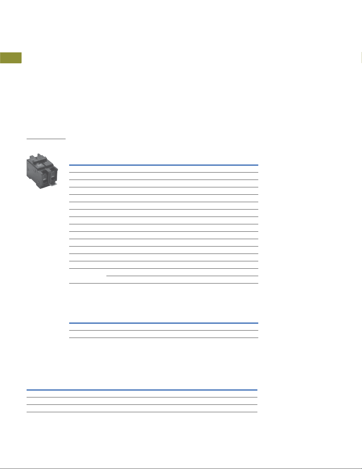
QUICKLAG Type QCD
Miniature Circuit
Breaker
1.1
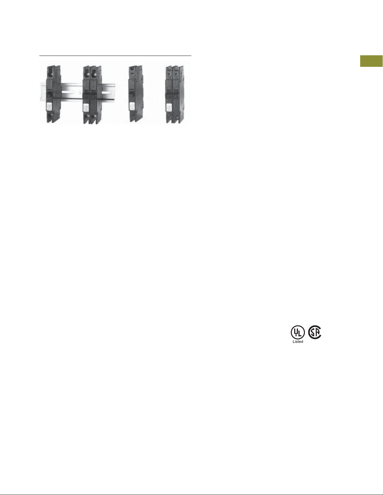
QUICKLAG Type QCD Miniature Circuit Breakers
1
QCD breakers are used
primarily in HVAC and
industrial applications.
1
●
1
1
1
1
Single-, two- and
three-pole options
●
Modular construction
●
DIN mounted
(symmetrical rail 35 x
7.5 DIN/EN 50 022)
●
QCD same profile as
Type QCR
Industrial Circuit Breakers
●
Flexible power feed
connection:
wire size, position
●
Same breaker size for
entire rating range
●
Field mountable
accessories:
finger shroud proof, quick
connect terminals
●
Other accessories:
jumper unit
1
1
1
1
1
1
1
1
1
1
1
1
1
1
1
1
1
QUICKLAG Type QCD 10,000A Interrupting Capacity Thermal-Magnetic Breakers
Continuous
Ampere Rating
at 40°C
10 QCD1010 QCD2010 — —
15 QCD1015 QCD2015 QCD2015H QCD3015H
20 QCD1020 QCD2020 QCD2020H QCD3020H
25 QCD1025 QCD2025 QCD2025H QCD3025H
30 QCD1030 QCD2030 QCD2030H QCD3030H
35 QCD1035 QCD2035 QCD2035H QCD3035H
40 QCD1040 QCD2040 QCD2040H QCD3040H
45 QCD1045 QCD2045 QCD2045H QCD3045H
50 QCD1050 QCD2050 QCD2050H QCD3050H
55 QCD1055 QCD2055 QCD2055H QCD3055H
60 QCD1060 QCD2060 QCD2060H QCD3060H
70 — QCD2070 QCD2070H QCD3070H
80 — QCD2080 QCD2080H QCD3080H
90 — QCD2090 QCD2090H QCD3090H
100 — QCD2090 QCD2090H QCD3100H
QUICKLAG Type QCD Non-Automatic Switches
Continuous
Ampere Rating
at 40°C
60 — — QCD2060NA —
100 ————
Single-Pole Two-Pole Two-Pole Three-Pole
120/240 Vac 120/240 Vac 240 Vac 240 Vac
Catalog Number Catalog Number Catalog Number Catalog Number
— QCD2100 QCD2100H —
Single-Pole Two-Pole Two-Pole Three-Pole
120/240 Vac 120/240 Vac 240 Vac 240 Vac
Catalog Number Catalog Number Catalog Number Catalog Number
1
Dimensions
Approximate Dimensions in Inches (mm)
1
Shipping Data
1
Number
of Poles
1
1 24 9.00 (4.1) 12.50 x 7.50 x 5.00 (317.5 x 190.5 x 127.0)
2 12 9.00 (4.1) 12.50 x 7.50 x 5.00 (317.5 x 190.5 x 127.0)
1
3 8 9.00 (4.1) 12.50 x 7.50 x 5.00 (317.5 x 190.5 x 127.0)
1
1
V4-T1-22 Volume 4—Circuit Protection CA08100005E—April 2019
Carton
Quantity
Approximate
Weight Lbs (kg) Dimensions
Miniature Circuit Breakers and Supplementary Protectors
Cable-In/Cable-Out, 1/2-Inch Wide, Types QCR, QCF, QCRH, QCFH
Industrial Circuit Breakers
1.1
Contents
Description Page
Quick Reference . . . . . . . . . . . . . . . . . . . . . . . . . . . . . V4-T1-2
QUICKLAG Plug-On Types HQP, QPHW, QHPX, QHPW V4-T1-5
QUICKLAG Plug-On Ground Fault and Equipment Protectors,
Types QPGFT, QPHGFT, QPGFEP, QPHGFEP . . . . .
Bolt-On Types BAB, QBHW, HBAX, HBAW . . . . . . . . V4-T1-11
Bolt-On Arc Fault Circuit Interrupter Types
QBAF, QBCAF. . . . . . . . . . . . . . . . . . . . . . . . . . . . . .
Bolt-On Ground Fault and Equipment Protectors,
Single-Pole Two-Pole Single-Pole Two-Pole
QCR (Rear-Mounted Breakers) QCF (Front-Mounted Breakers)
Types QBGFT, QBHGFT, QBGFEP, QBHGFEP . . . . .
Cable-In/Cable-Out Types QC, QCD, QCHW,
QHCX, QHCW . . . . . . . . . . . . . . . . . . . . . . . . . . . . .
Cable-In/Cable-Out, 1/2-Inch Wide, Types QCR, QCF,
QCRH, QCFH
Cable-In/Cable-Out Ground Fault and Equipment Protectors,
Types QCGFT, QCHGFT, QCGFEP, QCHGFEP . . . . .
Solenoid-Operated, Remote-Controlled Latching
Types BABRP, BABRSP, BRRP and CLRP. . . . . . . . .
Solenoid Operator—Remote Controlled Latching for
Type GHBS, GBHS and GHQRSP Breakers. . . . . . .
International Rated Types HQP, BA, QC, GFMB, GFXBC V4-T1-36
Special Application Breakers, Types HQP, BA, QC . . . V4-T1-39
Cable-In/Cable-Out, 1/2-Inch Wide, Types QCR, QCF, QCRH, QCFH
Product Description
Eaton Type QCR circuit
breakers have as a standard
feature provisions for 35 mm
DIN rail rear mounting with
a spring-loaded release.
Optional clips for individual
mounting are available as a
separate accessory.
Type QCF have two threaded
steel inserts to facilitate front
mounting with #6–32 steel
screws. The clamp type
terminals are accessible from
the rear of the breaker so that
cables can be accessed
without removal of the
breaker from the front cover.
Application Description
QCR and QCF circuit breakers
are only 1/2-inch (12.7 mm)
wide per pole and are
excellent for general purpose
industrial applications where
space savings is required.
Features, Benefits
and Functions
●
1/2-inch (12.7 mm) wide
per pole
●
Cable-in/cable-out
●
Black cases with black
handles
●
Three position handle:
ON, Tripped (center), OFF
●
Thermal-magnetic
protection
V4-T1-8
V4-T1-14
V4-T1-16
V4-T1-19
Product Selection. . . . . . . . . . . . . . . . . . . . . . . .
QCR and QCF Options and Accessories . . . . . . V4-T1-26
Standards and Certifications
●
Built and listed to UL 489
●
UL File No. E7819
●
CSA File No. LR48907
●
Type QCR and QCF circuit
breakers are UL listed
circuit breakers that are
suitable for use as branch
circuit protectors
●
All ratings 15–60A are
HACR rated
V4-T1-24
V4-T1-27
V4-T1-30
V4-T1-33
1
1
1
1
1
1
1
1
1
1
1
1
1
1
1
1
1
1
1
1
1
1
1
1
1
1
1
1
1
1
Volume 4—Circuit Protection CA08100005E—April 2019 V4-T1-23

1.1
Cable-In/Cable-Out,
1/2-Inch Wide
Product Selection
1
Miniature Circuit Breakers and Supplementary Protectors
Industrial Circuit Breakers
1
1
1
1
1
1
1
1
1
1
1
1
1
1
1
1
1
1
1
1
1
1
1
1
1
1
1
QCR Breaker Catalog Numbers
Continuous
Ampere Rating
at 40°C
QCR Breaker 10 kAIC Interrupting Ratings
10 QCR1010 QCR2010 — —
15 QCR1015
20 QCR1020
25 QCR1025 QCR2025 QCR2025H QCR3025H
30 QCR1030 QCR2030 QCR2030H QCR3030H
35 QCR1035 QCR2035 — —
40 QCR1040 QCR2040 — —
45 QCR1045 QCR2045 — —
50 QCR1050 QCR2050 — —
55 QCR1055 QCR2055 — —
7
60
QCR Breaker 22 kAIC Interrupting Ratings
15 QCRH1015
20 QCRH1020
Notes
1
Standard breaker terminals are box type lugs.
2
Breakers with T Catalog Number Suffix are suitable for line and load side ring terminal connection
(#10–32 plus/minus terminal screw provided).
3
Breakers with P Catalog Number Suffix are suitable for terminating two 10 AWG Quick-Connect Type Terminals per
phase on breaker load side.
4
Breakers with Shunt Trip (extra pole required on breaker right-hand side) are available on single-, two- and three-pole.
Contact the Customer Support Center at 1-800-356-1243.
5
Breakers with H Catalog Suffix have 240 Vac construction.
6
All 15 and 20A single-pole breakers are SWD (Switching Duty) rated for fluorescent lighting applications.
7
60/75°C Cu/Al wire on all ratings except 60A, which requires Cu only conductor.
Single-Pole Two-Pole Two-Pole Three-Pole
120/240 Vac 120/240 Vac 240 Vac
Catalog Number Catalog Number Catalog Number Catalog Number
QCR1010T QCR2010T — —
— QCR2010P — —
6
6
QCR1015T
— QCR2015P — —
6
6
QCR1020T
— QCR2020P — —
QCR1025T QCR2025T QCR2025HT QCR3025HT
— QCR2025P — —
QCR1030T QCR2030T QCR2030HT QCR3030HT
— QCR2030P — —
— QCR2035P — —
— QCR2040P — —
— QCR2045P — —
— QCR2050P — —
— QCR2055P — —
QCR1060 QCR2060 — —
— QCR2060P — —
6
QCRH1015T
6
QCRH1020T
1234
5
QCR2015 QCR2015H QCR3015H
QCR2015T QCR2015HT QCR3015HT
QCR2020 QCR2020H QCR3020H
QCR2020T QCR2020HT QCR3020HT
QCRH2015 — —
6
6
QCRH2015T — —
QCRH2020 — —
QCRH2020T — —
1
1
V4-T1-24 Volume 4—Circuit Protection CA08100005E—April 2019

Miniature Circuit Breakers and Supplementary Protectors
Cable-In/Cable-Out,
1/2-Inch Wide
Industrial Circuit Breakers
1.1
QCF Breaker Catalog Numbers
Continuous
Ampere Rating
at 40°C
QCF Breaker 10 kAIC Interrupting Ratings
10 QCF1010 QCF2010 — —
15 QCF1015
20 QCF1020
25 QCF1025 QCF2025 QCF2025H QCF3025H
30 QCF1030 QCF2030 QCF2030H QCF3030H
35 QCF1035 QCF2035 — —
40 QCF1040 QCF2040 — —
45 QCF1045 QCF2045 — —
50 QCF1050 QCF2050 — —
55 QCF1055 QCF2055 — —
6
60
QCF Breaker 22 kAIC Interrupting Ratings
15 QCFH1015
20 QCFH1020
Notes
1
Standard breaker terminals are box type lugs.
2
Breakers with T Catalog Number Suffix are suitable for line and load side ring terminal connection
(#10–32 plus/minus terminal screw provided).
3
Breakers with Shunt Trip Attachment (extra pole required on breaker right-hand side) are available.
Contact the Customer Support Center.
4
Breakers with H Catalog Suffix have 240 Vac construction.
5
All 15 and 20A single-pole breakers are SWD (Switching Duty) rated for fluorescent lighting applications.
6
60/75°C Cu/Al wire on all ratings except 60A, which requires Cu only conductor.
Single-Pole Two-Pole Two-Pole Three-Pole
120/240 Vac 120/240 Vac 240 Vac
Catalog Number Catalog Number Catalog Number Catalog Number
QCF1010T QCF2010T — —
5
5
QCF1015T
5
5
QCF1020T
QCF1025T QCF2025T QCF2025HT QCF3025HT
QCF1030T QCF2030T QCF2030HT QCF3030HT
QCF1060 QCF2060 — —
5
QCFH1015T
5
QCFH1020T
123
4
QCF2015 QCF2015H QCF3015H
QCF2015T QCF2015HT QCF3015HT
QCF2020 QCF2020H QCF3020H
QCF2020T QCF2020HT QCF3020HT
QCFH2015 — —
5
5
QCFH2015T — —
QCFH2020 — —
QCFH2020T — —
1
1
1
1
1
1
1
1
1
1
1
1
1
1
1
1
1
1
1
1
1
1
1
1
1
1
1
1
1
1
Volume 4—Circuit Protection CA08100005E—April 2019 V4-T1-25
1.1
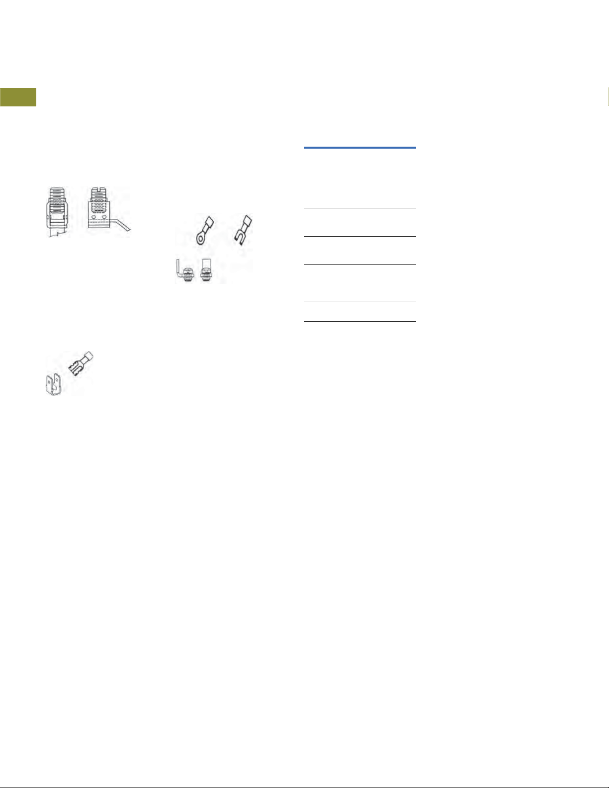
QCR and QCF Options and Accessories
1
QCR and QCF Standard Box
Ter m in al s
1
Factory-installed line and load
side breaker terminal to
1
accommodate14 AWG to
4 AWG wire.
1
Standard Box Terminals
1
1
1
1
QCR Quick-Connect Terminals
Factory-installed two-prong
1
quick-connect terminal on
breaker load side suitable for
1
terminating two 10 AWG wire
with insulated slip-on
1
terminals as shown. Line side
terminal is the standard type.
1
Catalog Suffix “P”
Miniature Circuit Breakers and Supplementary Protectors
Industrial Circuit Breakers
QCR and QCF Ring or Spade Lug
Terminals (10 to 30A Ratings
Only)
Factory-installed line and load
side terminals each equipped
with a #10–32 screw suitable
for terminating one 10 AWG
wire with insulated ring or
spade type terminal as shown.
Catalog Suffix “T”
Available QCR and QCF
Breaker Accessories
Description
Steel mounting clip
mounts QCR breaker if
individual mounting is
required. Quantity two
required for single- and twopole and four required
for three-pole breakers.
Removable padlock
device for single-pole
QCR or QCF breaker.
Removable padlock
device for multi-pole
QCR or QCF breaker.
Padlock bracket assembly for QCR or QCF
single- or multi-pole
breakers (OFF only).
Padlock bracket for
QCR, lock-off only.
Catalog
Number
QCRMTGFT
QCRFPL1P
QCRFPLMP
QCRFLOFF
QCRPLOFF
1
1
1
Technical Data and Specifications
1
●
Single-, two- and
1
1
1
three-pole
●
10 kAIC at 120/240 Vac,
10– 60A
●
22 kAIC at 120/240 Vac,
15–20A
●
10 kAIC at 240 Vac, 10–30A
1
1
1
1
1
1
1
●
3 kAIC at 62.5 Vdc
(single-pole)
●
3 kAIC at 130 Vdc
(two poles in series)
●
Normal operating
environment:
●
0–40°C
●
5–95% humidity
(noncondensing)
1
1
1
1
V4-T1-26 Volume 4—Circuit Protection CA08100005E—April 2019
Miniature Circuit Breakers and Supplementary Protectors
QUICKLAG Type QCGFT Single-Pole
Ground Fault Circuit Breaker
Industrial Circuit Breakers
1.1
Cable-In/Cable-Out Ground Fault and Equipment
Protectors, Types QCGFT, QCHGFT, QCGFEP, QCHGFEP
Product Description
QUICKLAG Ground Fault Circuit
Breakers, Class A GFCI
●
5 mA trip sensitivity
Standards and Certifications
QUICKLAG Ground Fault Circuit
Breakers, Class A GFCI
●
Built and tested to UL 943
Contents
Description Page
Quick Reference . . . . . . . . . . . . . . . . . . . . . . . . . . . . . V4-T1-2
QUICKLAG Plug-On Types HQP, QPHW, QHPX, QHPW V4-T1-5
QUICKLAG Plug-On Ground Fault and Equipment Protectors,
Types QPGFT, QPHGFT, QPGFEP, QPHGFEP . . . . .
Bolt-On Types BAB, QBHW, HBAX, HBAW . . . . . . . . V4-T1-11
Bolt-On Arc Fault Circuit Interrupter Types
QBAF, QBCAF. . . . . . . . . . . . . . . . . . . . . . . . . . . . . .
Bolt-On Ground Fault and Equipment Protectors,
Types QBGFT, QBHGFT, QBGFEP, QBHGFEP . . . . .
Cable-In/Cable-Out Types QC, QCD, QCHW,
QHCX, QHCW . . . . . . . . . . . . . . . . . . . . . . . . . . . . .
Cable-In/Cable-Out, 1/2-Inch Wide, Types QCR, QCF,
QCRH, QCFH . . . . . . . . . . . . . . . . . . . . . . . . . . . . . .
Cable-In/Cable-Out Ground Fault and Equipment Protectors,
Types QCGFT, QCHGFT, QCGFEP, QCHGFEP
Product Selection. . . . . . . . . . . . . . . . . . . . . . . .
Wiring Diagram . . . . . . . . . . . . . . . . . . . . . . . . . V4-T1-29
Dimensions . . . . . . . . . . . . . . . . . . . . . . . . . . . . V4-T1-29
Solenoid-Operated, Remote-Controlled Latching
Types BABRP, BABRSP, BRRP and CLRP. . . . . . . . .
Solenoid Operator—Remote Controlled Latching for
Type GHBS, GBHS and GHQRSP Breakers. . . . . . .
International Rated Types HQP, BA, QC, GFMB, GFXBC V4-T1-36
Special Application Breakers, Types HQP, BA, QC . . . V4-T1-39
V4-T1-8
V4-T1-14
V4-T1-16
V4-T1-19
V4-T1-23
V4-T1-28
V4-T1-30
V4-T1-33
1
1
1
1
1
1
1
1
1
1
1
1
1
1
1
1
1
QUICKLAG Ground Fault
Equipment Protectors
●
30 mA trip sensitivity
QUICKLAG Ground Fault
Equipment Protectors
●
Built and tested to
UL 1053
1
1
1
1
1
1
1
1
1
1
1
1
1
Volume 4—Circuit Protection CA08100005E—April 2019 V4-T1-27

1.1
QUICKLAG Type QCGFT
Single-Pole Ground
Fault Circuit Breaker
Product Selection
1
1
1
1
1
1
1
1
1
1
1
1
1
1
1
1
1
1
1
1
1
1
1
1
1
1
1
1
1
1
Miniature Circuit Breakers and Supplementary Protectors
Industrial Circuit Breakers
Breaker Catalog Numbers
Continuous
Ampere Rating
at 40°C
Ground Fault Circuit Breakers—5 mA Sensitivity
QUICKLAG Type: QCGFT 10,000A Interrupting Capacity Thermal-Magnetic Breakers
15 QCGFT1015 QCGFT2015
20 QCGFT1020 QCGFT2020
25 QCGFT1025 QCGFT2025
30 QCGFT1030 QCGFT2030
40 QCGFT1040 QCGFT2040
50 — QCGFT2050
QUICKLAG Type: QCHGFT 22,000A Interrupting Capacity Thermal-Magnetic Breakers
15 QCHGFT1015 QCHGFT2015
20 QCHGFT1020 QCHGFT2020
25 QCHGFT1025 QCHGFT2025
30 QCHGFT1030 QCHGFT2030
Ground Fault Equipment Protectors—30 mA Sensitivity
QUICKLAG Type: QCGFEP 10,000A Interrupting Capacity Thermal-Magnetic Breakers
15 QCGFEP1015 QCGFEP2015
20 QCGFEP1020 QCGFEP2020
25 QCGFEP1025 QCGFEP2025
30 QCGFEP1030 QCGFEP2030
40 QCGFEP1040 QCGFEP2040
50 — QCGFEP2050
QUICKLAG Type: QCHGFEP 22,000A Interrupting Capacity Thermal-Magnetic Breakers
15 QCHGFEP1015 QCHGFEP2015
20 QCHGFEP1020 QCHGFEP2020
25 QCHGFEP1025 QCHGFEP2025
30 QCHGFEP1030 QCHGFEP2030
Special Application Ground Fault Circuit Protector—5 mA Sensitivity
QUICKLAG Type: QCGFT 10,000A Interrupting Capacity with Bell Alarm (W1) or
Auxiliary Switch (W2)
15 QCGFT1015W1 QCGFT2015W1
20 QCGFT1020W1 QCGFT2020W1
25 QCGFT1025W1 QCGFT2025W1
30 QCGFT1030W1 QCGFT2030W1
40 — QCGFT2040W1
50 — QCGFT2050W1
15 QCGFT1015W2 —
20 QCGFT1020W2 —
25 QCGFT1025W2 —
30 QCGFT1030W2 —
Special Application Ground Fault Equipment Protectors—30 mA Sensitivity
QUICKLAG Type: QCGFEP 10,000A Interrupting Capacity with Bell Alarm (W1) or
Auxiliary Switch (W2)
15 QCGFEP1015W1 QCGFEP2015W1
20 QCGFEP1020W1 QCGFEP2020W1
25 QCGFEP1025W1 QCGFEP2025W1
30 QCGFEP1030W1 QCGFEP2030W1
40 — QCGFEP2040W1
50 — QCGFEP2050W1
15 QCGFEP1015W2 —
20 QCGFEP1020W2 —
25 QCGF
30 QCGFEP1030W2
Single-Pole Two-Pole
120 Vac 120/240 Vac
Catalog Number Catalog Number
EP
1025W2 —
—
V4-T1-28 Volume 4—Circuit Protection CA08100005E—April 2019

Miniature Circuit Breakers and Supplementary Protectors
Blue Wire
Red Wire
Black Wire
Ground
Fault
Breaker
Single-throw double-pole contacts are UL and CSA listed for 5A at 250 Vac.
Bell Alarm (W1)—contacts change state when breaker trips.
Auxiliary Switch (W2)—contacts change state when breaker is opened (or tripped) or closed.
14-inch (355.6 mm) long 18 AWG pigtail wire leads provided.
Blue
Red
NC
NO
Industrial Circuit Breakers
1.1
Wiring Diagram
Bell Alarm and Auxiliary Contact Schematic
Dimensions
Approximate Dimensions in Inches (mm)
Shipping Data
Number
of Poles
1 20 11.00 (5.0) 12.50 x 6.50 x 5.00 (317.5 x 165.1 x 127.0)
2 5 5.00 (2.3) 15.50 x 6.00 x 4.50 (393.7 x 152.4 x 114.3)
Carton
Quantity
Approximate
Weight Lbs (kg) Dimensions
1
1
1
1
1
1
1
1
1
1
1
1
1
1
1
1
1
1
1
1
1
1
1
1
1
1
1
1
1
1
Volume 4—Circuit Protection CA08100005E—April 2019 V4-T1-29

1.1
BABRP and BABRSP Breakers—
Single- and Two-Pole
Miniature Circuit Breakers and Supplementary Protectors
Industrial Circuit Breakers
1
1
1
1
1
1
1
1
1
1
1
1
1
Solenoid-Operated, Remote-Controlled Latching
1
Types BABRP, BABRSP, BRRP and CLRP
1
Product Description
The BABRP and BABRSP
1
are bolt-on branch circuit
breakers designed for use in
1
panelboards. The BRRP is a
plug-on branch circuit breaker
designed for use in load-
1
centers not manufactured
with breakers with a 1-inch
1
wide format and are listed on
the “Compatibility list for
1
Classified Applications”—
Pub. 26271. In addition to
1
providing conventional branch
circuit protection, they include
a unique solenoid-operated
1
mechanism that provides for
efficient breaker pulse-on and
1
pulse-off opera
with a suitable controller
1
Eaton’s Pow-R-Command™
lighting control system.
These breakers can also be
1
controlled by pushbutton or
a PLC unit.
1
tion when used
like
Application Description
Eaton’s BABRP, BABRSP,
BRRP and CLRP breakers are
remotely operated molded
case circuit breakers ideally
suited for lighting control
applications or energy
management applications.
Contents
Description Page
Quick Reference. . . . . . . . . . . . . . . . . . . . . . . . . . . . . . V4-T1-2
QUICKLAG Plug-On Types HQP, QPHW, QHPX, QHPW V4-T1-5
QUICKLAG Plug-On Ground Fault and Equipment Protectors,
Types QPGFT, QPHGFT, QPGFEP, QPHGFEP. . . . . .
Bolt-On Types BAB, QBHW, HBAX, HBAW . . . . . . . . V4-T1-11
Bolt-On Arc Fault Circuit Interrupter Types
QBAF, QBCAF . . . . . . . . . . . . . . . . . . . . . . . . . . . . . .
Bolt-On Ground Fault and Equipment Protectors,
Types QBGFT, QBHGFT, QBGFEP, QBHGFEP . . . . .
Cable-In/Cable-Out Types QC, QCD, QCHW,
QHCX, QHCW. . . . . . . . . . . . . . . . . . . . . . . . . . . . . .
Cable-In/Cable-Out, 1/2-Inch Wide, Types QCR, QCF,
QCRH, QCFH . . . . . . . . . . . . . . . . . . . . . . . . . . . . . .
Cable-In/Cable-Out Ground Fault and Equipment Protectors,
Types QCGFT, QCHGFT, QCGFEP, QCHGFEP . . . . .
Solenoid-Operated, Remote-Controlled Latching
Types BABRP, BABRSP, BRRP and CLRP
Product Selection. . . . . . . . . . . . . . . . . . . . . . . .
Technical Data and Specifications . . . . . . . . . . . V4-T1-32
Wiring Diagrams . . . . . . . . . . . . . . . . . . . . . . . . V4-T1-32
Solenoid Operator—Remote Controlled Latching for
Type GHBS, GBHS and GHQRSP Breakers . . . . . . .
International Rated Types HQP, BA, QC, GFMB, GFXBC V4-T1-36
Special Application Breakers, Types HQP, BA, QC . . . V4-T1-39
Features, Benefits and Functions
●
Bolt-on line-side terminal
(BABRP, BABRSP—
Type BA)
●
Plug-on line-side terminal
(BRRP—Type BR, CLRP—
Type CL)
●
Cable connected load-side
terminal
●
Four-position control
terminal
●
Bi-metal assembly for
thermal overload
protection
●
Fast-acting short-circuit
protection
●
Arc-chute assembly for
fast-acting arc extinction
●
Three-position handle: OFF,
TRIP (Center), ON
●
Handle permits manual
switching when control
power is lost
●
Mechanical trip indicator
●
15 and 20A breakers SWD
(switching duty) rated
●
HID ratings for HID (high
intensity discharge) lighting
●
All models HACR rated
●
Status feedback of control
circuit (BABRSP)
●
Series rated (BABRP,
BABRSP only)
●
BRRP series rated same
as BR breakers
●
BABRP, BABRSP same
as BA breakers
V4-T1-8
V4-T1-14
V4-T1-16
V4-T1-19
V4-T1-23
V4-T1-27
V4-T1-31
V4-T1-33
1
1
1
1
V4-T1-30 Volume 4—Circuit Protection CA08100005E—April 2019

Miniature Circuit Breakers and Supplementary Protectors
QUICKLAG Type QCGFT
Single-Pole Ground
Fault Circuit Breaker
Industrial Circuit Breakers
1.1
Product Selection
BABRP UL 489 and CSA 22.2 Interrupting
Ratings
Interrupting Capacity (Symmetrical Amperes)
Number
of Poles
1 15 10,000 — — BABRP1015
2 15 — 10,000 — BABRP2015
BABRP and BABRSP Wire Harness
Description
This 60-inch (1524.0 mm) wire pigtail provides
a connection from a single BABRP’s control plug to
a customer’s pushbutton, relay or PLC. Each box
contains 12 pigtails. Wires are 22 AWG, 600V.
Order in multiples of 12.
BABRSP UL 489 and CSA 22.2 Interrupting
Ratings
Number
of Poles
1 15 10,000 — — BABRSP1015
2 15 — 10,000 — BABRSP2015
Vac (50/60 Hz)
Ampere
1
Rating
20 10,000 — — BABRP1020
25 10,000 — — BABRP1025
30 10,000 — — BABRP1030
20 — 10,000 — BABRP2020
25 — 10,000 — BABRP2025
30 — 10,000 — BABRP2030
Interrupting Capacity (Symmetrical Amperes)
Vac (50/60 Hz)
Ampere
1
Rating
20 10,000 — — BABRSP1020
25 10,000 — — BABRSP1025
30 10,000 — — BABRSP1030
20 — 10,000 — BABRSP2020
25 — 10,000 — BABRSP2025
30 — 10,000 — BABRSP2030
Catalog
Number 120 120/240 277/480
Catalog
Number
SLBKRPTL1
Catalog
Number120 120/240 277/480
BRRP UL 489 and CSA 22.2 Interrupting
Ratings
Interrupting Capacity (Symmetrical Amperes)
Number
Ampere
of Poles
Rating
1 15 10,000 — BRRP115
20 10,000 — BRRP120
25 10,000 — BRRP125
30 10,000 — BRRP130
2 15 — 10,000 BRRP215
20 — 10,000 BRRP220
25 — 10,000 BRRP225
30 — 10,000 BRRP230
CLRP UL 489 and CSA 22.2 Interrupting
Ratings
Interrupting Capacity (Symmetrical Amperes)
Number
Ampere
of Poles
Rating
1 15 10,000 — CLRP115
20 10,000 — CLRP120
25 10,000 — CLRP125
30 10,000 — CLRP130
2 15 — 10,000 CLRP215
20 — 10,000 CLRP220
25 — 10,000 CLRP225
30 — 10,000 CLRP230
Note
1
Continuous current rating at 40°C.
Vac (50/60 Hz)
Vac (50/60 Hz)
Catalog
Number120 120/240
Catalog
Number120 120/240
1
1
1
1
1
1
1
1
1
1
1
1
1
1
1
1
1
1
1
1
1
1
1
1
1
1
1
1
1
1
Volume 4—Circuit Protection CA08100005E—April 2019 V4-T1-31

1.1
Line
Remote
Contact
Breaker
Contact
RM
b
RM
a
Red
Black
Yellow
Blue
On
Coil
Off
Coil
Remote
Status
Load
Line
Remote
Contact
Breaker
Contact
RM
b
RM
a
Red
Black
Yellow
Blue
On
Coil
Off
Coil
Remote
Status
BKR
a
BABRP
BABRSP
Load
Miniature Circuit Breakers and Supplementary Protectors
Industrial Circuit Breakers
Technical Data and Specifications
1
Solenoid Operating Data
●
1
1
1
1
1
1
1
1
1
1
1
1
Power requirements: 24
Vac/dc (20.4V minimum–
30V maximum)
●
Controlled signal:
+AC/DC 8 ms minimum
with zero cross, 300 ms
maximum
●
AC: 1.3 cycles minimum,
18 cycles or 300 ms
maximum
●
DC: 8 ms minimum,
300 ms maximum
●
Maximum duty cycle of
6 OPEN/CLOSE cycles
per minute
●
Current draw: open 1A,
close 3/4A
●
Blue wire: power input
(see power requirements)
●
Black wire: remote opening
●
Red wire: remote closing
●
Yellow wire: feedback
status from power input,
maximum 0.50A draw
(BABRSP only)
1
1
1
Operation
●
Tripping system—the
BABRP, BABRSP, BRRP
and CLRP circuit breakers
have a permanent trip
unit that contains a factory
preset thermal (overload)
trip element in each pole
●
Operating mechanism—
the BABRP, BABRSP, BRRP
and CLRP circuit breakers
have an over-center toggle
mechanism that provides
quick-make, quick-break
operation. The operating
mechanism is trip free. An
internal cross-bar provides
a common tripping of all
multi-pole circuit breakers
Operating/Application Data
●
Ambient temperature:
0 to 40°C
●
Nominal pulse magnitude:
24 Vac/dc
●
Frequency: 50/60 Hz
●
Maximum breaker cycling:
6 operations per minute
●
Tolerance: +10% to –15%
of nominal voltage
●
Humidity: 0 to 95%
noncondensing
Wiring Diagrams
Control Circuit for the BABRP and BABRSP
1
1
1
1
1
1
1
1
1
1
1
1
1
1
V4-T1-32 Volume 4—Circuit Protection CA08100005E—April 2019
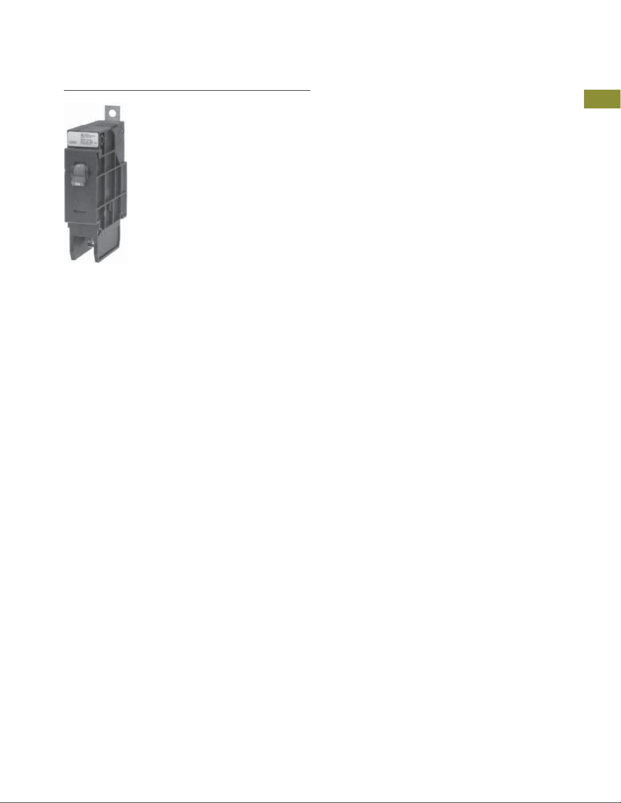
Miniature Circuit Breakers and Supplementary Protectors
GHBS and GHQRSP
Industrial Circuit Breakers
1.1
Solenoid Operator—Remote-Controlled Latching
for Type GHBS, GBHS and GHQRSP Breakers
Product Description
Eaton’s GHBS, GBHS and
GHQRSP circuit breakers
are bolt-on branch circuit
breakers designed for use
in 277/480 Vac panelboards.
In addition to providing
conventional branch circuit
protection, they include a
unique solenoid-operated
mechanism that provides
for efficient breaker pulse-on
and pulse-off operation
when used with a suitable
controller like Eaton’s
Pow-R-Command lighting
control system.
Features, Benefits
and Functions
●
Bolt-on line-side terminal
●
Cable-connected load-side
terminal
●
Status switch—remote
status and breaker status
available from internal
auxiliary switches
●
Bi-metal assembly for
thermal overload
protection
●
Fast-acting short-circuit
protection
●
Arc-runner and arc-chute
assembly for fast-acting arc
extinction
●
Three-position breaker
handle: OFF, TRIP (Center),
ON
Contents
Description Page
Quick Reference . . . . . . . . . . . . . . . . . . . . . . . . . . . . . V4-T1-2
QUICKLAG Plug-On Types HQP, QPHW, QHPX, QHPW V4-T1-5
QUICKLAG Plug-On Ground Fault and Equipment Protectors,
Types QPGFT, QPHGFT, QPGFEP, QPHGFEP . . . . .
Bolt-On Types BAB, QBHW, HBAX, HBAW . . . . . . . . V4-T1-11
Bolt-On Arc Fault Circuit Interrupter Types
QBAF, QBCAF. . . . . . . . . . . . . . . . . . . . . . . . . . . . . .
Bolt-On Ground Fault and Equipment Protectors,
Types QBGFT, QBHGFT, QBGFEP, QBHGFEP . . . . .
Cable-In/Cable-Out Types QC, QCD, QCHW,
QHCX, QHCW . . . . . . . . . . . . . . . . . . . . . . . . . . . . .
Cable-In/Cable-Out, 1/2-Inch Wide, Types QCR, QCF,
QCRH, QCFH . . . . . . . . . . . . . . . . . . . . . . . . . . . . . .
Cable-In/Cable-Out Ground Fault and Equipment Protectors,
Types QCGFT, QCHGFT, QCGFEP, QCHGFEP . . . . .
Solenoid-Operated, Remote-Controlled Latching
Types BABRP, BABRSP, BRRP and CLRP. . . . . . . . .
Solenoid Operator—Remote Controlled Latching for
Type GHBS, GBHS and GHQRSP Breakers
Product Selection. . . . . . . . . . . . . . . . . . . . . . . .
Technical Data and Specifications . . . . . . . . . . . V4-T1-35
Wiring Diagrams . . . . . . . . . . . . . . . . . . . . . . . . V4-T1-35
International Rated Types HQP, BA, QC, GFMB, GFXBC V4-T1-36
Special Application Breakers, Types HQP, BA, QC . . . V4-T1-39
●
Visual indication of the
remotely operated
contact’s position (open,
closed or trip)
●
Remote override handle
permits manual switching
when control power is lost
●
15 and 20A breakers SWD
(switching duty) rated.
●
15 and 20A breakers HID
rated for HID (High
intensity discharge) lighting
●
All models HACR rated
●
Series rated with various
Eaton main circuit breakers
V4-T1-8
V4-T1-14
V4-T1-16
V4-T1-19
V4-T1-23
V4-T1-27
V4-T1-30
V4-T1-34
1
1
1
1
1
1
1
1
1
1
1
1
1
1
1
1
1
1
1
1
1
1
1
1
1
Volume 4—Circuit Protection CA08100005E—April 2019 V4-T1-33
1
1
1
1
1

1.1
GHBS—Single-Pole
Product Selection
1
1
1
1
1
1
1
Miniature Circuit Breakers and Supplementary Protectors
Industrial Circuit Breakers
GHQ UL 489 Interrupting Ratings
Interrupting Capacity (Symmetrical Amperes)
Number
of Poles
1 15 65,000 65,000 14,000 14,000
1 20 65,000 65,000 14,000 14,000
1 30 65,000 65,000 14,000 14,000
2 15 65,000 65,000 14,000 14,000
2 20 65,000 65,000 14,000 14,000
2 30 65,000 65,000 14,000 14,000
Ampere
Rating
Vac (50/60 Hz)
1
120 120/240 277 480Y/277
Catalog Number
1
1
1
1
1
1
1
1
1
1
1
1
1
1
1
1
1
1
1
1
GHBS UL 489 Interrupting Ratings
Interrupting Capacity (Symmetrical Amperes)
Number
of Poles
1 15 65,000 — 14,000 GHBS1015D
2 15 — 65,000 14,000 GHBS2015D
GBHS CSA 22.2 Interrupting Ratings (Not UL Listed)
Number
of Poles
1 15 10,000 GBHS1015D
2 15 10,000 GBHS2015D
GHQRSP UL 489 and CSA 22.2 Interrupting Ratings
Number
of Poles
1 15 65,000 65,000 14,000 14,000
2 15 65,000 65,000 14,000 14,000
Notes
1
Continuous current rating at 40°C.
2
All UL listed circuit breakers are HID (high intensity discharge) rated.
Ampere
Rating
20 65,000 — 14,000 GHBS1020D
30 65,000 — 14,000 GHBS1030D
20 — 65,000 14,000 GHBS2020D
30 — 65,000 14,000 GHBS2030D
Interrupting Capacity (Symmetrical Amperes)
Ampere
Rating
20 10,000 GBHS1020D
20 10,000 GBHS2020D
Interrupting Capacity (Symmetrical Amperes)
Ampere
Rating
20 65,000 65,000 1 4,000 14,000
30 65,000 65,000 1 4,000 14,000
20 65,000 65,000 1 4,000 14,000
30 65,000 65,000 1 4,000 14,000
Vac (50/60 Hz)
1
Vac (50/60 Hz)
1
Vac (50/60 Hz)
1
120 120/240 277 480Y/277
Catalog Number 120 240 277/480
Catalog Number347/600
Catalog Number
GHQRSP1015
GHQRSP1020
GHQRSP1030
GHQRSP2015
GHQRSP2020
GHQRSP2030
2
1
1
1
V4-T1-34 Volume 4—Circuit Protection CA08100005E—April 2019

Miniature Circuit Breakers and Supplementary Protectors
Circuit Breaker
Solenoid
Solenoid
a
Common
28 Vac
AMP Inc.
Conductor
Plug
1
/2 Cycle
Maximum
28 Vac
Pulse Source
Circuit Breaker
Open/Closed
Status
Auxiliary
Industrial Circuit Breakers
1.1
Technical Data and Specifications
Solenoid Operating Data
●
Power requirements: 24
Vac/dc (20.4V minimum–
30V maximum)
●
Controlled signal: +AC/
DC 8 ms minimum with
zero cross, 300 ms
maximum
●
AC: 1.3 cycles minimum,
18 cycles or 300 ms
maximum
●
DC: 8 ms minimum,
300 ms maximum
●
Maximum duty cycle of
6 OPEN/CLOSE cycles
per minute
●
Current draw: open 1A,
close 3/4A
●
Blue wire: power input
(see power requirements)
●
Black wire: remote opening
Terminal Type
Circuit Breaker
Typ e
GHQRSP 15–20 Slotted Clamp #14–#4 AWG
Circuit Breaker
Amperes
●
Red wire: remote closing
●
Yellow wire: feedback
status from power input,
maximum 0.50A draw
Operation
Mechanism manually
operated by external handle
allowing ON, OFF and RESET
operation. Handle assumes a
center TRIP position after
performing protective
response.
Operating/Application Data
●
Ambient temperature:
0–40°C
●
Frequency: 48–62 Hz
●
Humidity: 0–95%
noncondensing
Screw
Head Type
Terminal
Type Range
Wiring Diagrams
Typical Single-Pole Circuit Breaker Schematic Diagram for
GHBS and GBHS Breakers
1
Typical Single-Pole Circuit Breaker Schematic Diagram for
GHQRSP Breakers
GHQRSP
Remote
Contact
Load
Breaker
Contact
Line
1
1
1
1
1
1
1
1
1
1
1
1
1
1
1
1
Yellow
Status
Red
On
Coil
Black
Off
Coil
Blue
Power
Input
1
1
1
Dimensions
Approximate Dimensions in Inches (mm)
Dimensions per Pole
Circuit Breaker Type Width Height
GHQRSP 1.00 (25.4) 4.63 (117.6) 2.81 (71.4)
Notes
1
Purchase separate AMP Inc. conductor plug #640426-3.
2
Excluding line terminal.
3
Excluding handle.
2
Length
3
1
1
1
1
1
1
1
1
1
1
1
Volume 4—Circuit Protection CA08100005E—April 2019 V4-T1-35

1.1
International Rated
Miniature Circuit Breakers and Supplementary Protectors
Industrial Circuit Breakers
1
1
1
1
1
1
1
1
1
1
1
1
1
International Rated Types HQP, BA, QC, GFMB, GFXBC
1
Product Description
1
QUICKLAG International Circuit
Breakers
1
●
Bolt-on Type BA
1
QUICKLAG International Ground
Fault Circuit Breakers
1
●
Plug-on Type GFMB
●
1
Cable-in/cable-out Type
GFXBC
1
1
Standards and Certifications
QUICKLAG International Circuit
Breakers
●
Built and test certified to
BS3871, Pt. 1
●
50/60 Hz, 40°C
QUICKLAG International Ground
Fault Circuit Breakers
●
Built and test certified to
BS3871, Pt. 1; BS3871,
Section 31-C; BS4293
●
50/60 Hz, 40°C; 30 mA
sensitivity
Contents
Description Page
Quick Reference. . . . . . . . . . . . . . . . . . . . . . . . . . . . . . V4-T1-2
QUICKLAG Plug-On Types HQP, QPHW, QHPX, QHPW V4-T1-5
QUICKLAG Plug-On Ground Fault and Equipment Protectors,
Types QPGFT, QPHGFT, QPGFEP, QPHGFEP . . . . .
Bolt-On Types BAB, QBHW, HBAX, HBAW . . . . . . . . V4-T1-11
Bolt-On Arc Fault Circuit Interrupter Types
QBAF, QBCAF . . . . . . . . . . . . . . . . . . . . . . . . . . . . . .
Bolt-On Ground Fault and Equipment Protectors,
Types QBGFT, QBHGFT, QBGFEP, QBHGFEP . . . . .
Cable-In/Cable-Out Types QC, QCD, QCHW,
QHCX, QHCW. . . . . . . . . . . . . . . . . . . . . . . . . . . . . .
Cable-In/Cable-Out, 1/2-Inch Wide, Types QCR, QCF,
QCRH, QCFH . . . . . . . . . . . . . . . . . . . . . . . . . . . . . .
Cable-In/Cable-Out Ground Fault and Equipment Protectors,
Types QCGFT, QCHGFT, QCGFEP, QCHGFEP . . . . .
Solenoid-Operated, Remote-Controlled Latching
Types BABRP, BABRSP, BRRP and CLRP. . . . . . . . .
Solenoid Operator—Remote Controlled Latching for
Type GHBS, GBHS and GHQRSP Breakers . . . . . . .
International Rated Types HQP, BA, QC, GFMB, GFXBC
Product Selection . . . . . . . . . . . . . . . . . . . . . . . .
Technical Data and Specifications . . . . . . . . . . . . V4-T1-38
Dimensions . . . . . . . . . . . . . . . . . . . . . . . . . . . . . V4-T1-38
Special Application Breakers, Types HQP, BA, QC . . . V4-T1-39
V4-T1-8
V4-T1-14
V4-T1-16
V4-T1-19
V4-T1-23
V4-T1-27
V4-T1-30
V4-T1-33
V4-T1-37
1
1
1
1
1
1
1
1
1
V4-T1-36 Volume 4—Circuit Protection CA08100005E—April 2019

Miniature Circuit Breakers and Supplementary Protectors
BAB
Industrial Circuit Breakers
1.1
Product Selection
Breaker Catalog Numbers
Continuous
Ampere Rating
at 40°C
3000A Interrupting Capacity (M3) Bolt-On Thermal-Magnetic Circuit Breakers
10 BAB1010E BAB2010E BAB3010E
15 BAB1015E BAB2015E BAB3015E
16 ———
20 BAB1020E BAB2020E BAB3020E
25 BAB1025E BAB2025E BAB3025E
30 BAB1030E BAB2030E BAB3030E
32 ———
40 BAB1040E BAB2040E BAB3040E
50 BAB1050E BAB2050E BAB3050E
60 BAB1060E BAB2060E BAB3060E
70 BAB1070E BAB2070E BAB3070E
90 — BAB2090E BAB3090E
100 — BAB2100E BAB3100E
6000A Interrupting Capacity (M6) Bolt-On Thermal-Magnetic Circuit Breakers
15 BAB1015HE BAB2015HE BAB3015HE
20 BAB1020HE BAB2020HE BAB3020HE
25 BAB1025HE BAB2025HE BAB3025HE
30 BAB1030HE BAB2030HE BAB3030HE
40 BAB1040HE BAB2040HE BAB3040HE
50 BAB1050HE BAB2050HE BAB3050HE
60 BAB1060HE BAB2060HE BAB3060HE
70 BAB1070HE BAB2070HE BAB3070HE
90 — BAB2090HE BAB3090HE
100 — BAB2100HE BAB3100HE
Single-Pole Two-Pole Three-Pole
240/415 Vac 240/415 Vac 240/415 Vac
Catalog Number Catalog Number Catalog Number
1
1
1
1
1
1
1
1
1
1
1
1
1
1
1
1
1
1
Breaker Catalog Numbers—Ground Fault Single-Pole 30 mA Sensitivity
Continuous
Ampere Rating
at 40°C
3000A Interrupting Capacity (M3) Plug-On Thermal-Magnetic Circuit Breakers
10 GFMB110B2
15 GFMB115B2
16 GFMB116B2
20 GFMB120B2
25 GFMB125B2
30 GFMB130B2
32 GFMB132B2
40 GFMB140B2
Note
For other 240/415V applications, please contact the Customer Support Center at 1-800-356-1243.
240/415 Vac
Catalog Number
Volume 4—Circuit Protection CA08100005E—April 2019 V4-T1-37
1
1
1
1
1
1
1
1
1
1
1
1

Miniature Circuit Breakers and Supplementary Protectors
1.1
Technical Data and Specifications
1
Interrupting Ratings
1
Ratin gs Suffix E Suffix HE
International Circuit Breakers
1
1
1
1
1
1
1
1
1
1
1
1
1
®
NEMA
120/240 Vac
BS3871 220/380,
240/415 Vac
International Ground Fault Circuit Breakers
BS3871 220/380,
240/415 Vac
Dimensions
Approximate Dimensions in Inches (mm)
Shipping Data
Miniature
Circuit Breaker
QUICKLAG Type B 1 24 9.00 (4.1) 12.50 x 7.50 x 5.00 (317.5 x 190.5 x 127.0)
QUICKLAG Ground Fault
Type P—All 1 20 11.00 (5.0) 12.50 x 6.50 x 5.00 (317.5 x 165.1 x 127.0)
Types B and C—All 1 20 11.00 (5.0) 12.50 x 7.00 x 5.50 (317.5 x 177.8 x 139.7)
Types P and B—All 2 5 5.00 (2.3) 12.50 x 6.00 x 4.50 (317.5 x 152.4 x 114.3)
Industrial Circuit Breakers
10,000 AIC 10,000 AIC
3000 AIC 6000 AIC
3000 AIC
Number
of Poles
2 12 9.00 (4.1) 12.50 x 7.50 x 5.00 (317.5 x 190.5 x 127.0)
3 8 9.00 (4.1) 12.50 x 7.50 x 5.00 (317.5 x 190.5 x 127.0)
Standard Carton
Quantity
Approximate Carton
Weight Lbs (kg)
Approximate
Standard Carton
1
1
1
1
1
1
1
1
1
1
1
1
1
1
1
V4-T1-38 Volume 4—Circuit Protection CA08100005E—April 2019

Miniature Circuit Breakers and Supplementary Protectors
QUICKLAG Type P Switching Neutral
Industrial Circuit Breakers
1.1
Special Application Breakers, Types HQP, BA, QC
Product Description
Breakers
●
Plug-on Type HQP:
10–30A, single- and
two-pole, 10 kAIC
●
Bolt-on Type BA: 10–30A,
single- and two-pole,
10 kAIC
●
Cable-in Type QC: 10–30A,
single- and two-pole,
10 kAIC
Switching neutral QUICKLAG
breakers available in singleand two-pole configurations,
plus neutral pole for
applications in accordance
with NEC
380.2. A single-pole device
takes two pole spaces, and a
two-pole device takes three
pole spaces.
®
514.5, 240.22 and
QUICKLAG HID (High Intensity
Discharge) Breakers
●
Plug-on Type HQP:
15–60A, single- and
two-pole, 10 kAIC
●
Bolt-on Type BA: 15–60A,
single- and two-pole,
10 k AIC
●
Cable-in Type QC: 15–60A,
single- and two-pole,
10 k AIC
Breakers designed
specifically for use with high
intensity discharge (HID)
lighting applications. (UL
listed as standard lighting
breakers.)
Contents
Description Page
Quick Reference . . . . . . . . . . . . . . . . . . . . . . . . . . . . . . V4-T1-2
QUICKLAG Plug-On Types HQP, QPHW, QHPX, QHPW V4-T1-5
QUICKLAG Plug-On Ground Fault and Equipment Protectors,
Types QPGFT, QPHGFT, QPGFEP, QPHGFEP . . . . . .
Bolt-On Types BAB, QBHW, HBAX, HBAW . . . . . . . . . V4-T1-11
Bolt-On Arc Fault Circuit Interrupter Types
QBAF, QBCAF. . . . . . . . . . . . . . . . . . . . . . . . . . . . . . .
Bolt-On Ground Fault and Equipment Protectors,
Types QBGFT, QBHGFT, QBGFEP, QBHGFEP . . . . . .
Cable-In/Cable-Out Types QC, QCD, QCHW,
QHCX, QHCW . . . . . . . . . . . . . . . . . . . . . . . . . . . . . .
Cable-In/Cable-Out, 1/2-Inch Wide, Types QCR, QCF,
QCRH, QCFH . . . . . . . . . . . . . . . . . . . . . . . . . . . . . . .
Cable-In/Cable-Out Ground Fault and Equipment Protectors,
Types QCGFT, QCHGFT, QCGFEP, QCHGFEP . . . . . .
Solenoid-Operated, Remote-Controlled Latching
Types BABRP, BABRSP, BRRP and CLRP. . . . . . . . . .
Solenoid Operator—Remote Controlled Latching for
Type GHBS, GBHS and GHQRSP Breakers. . . . . . . .
International Rated Types HQP, BA, QC, GFMB, GFXBC V4-T1-36
Special Application Breakers, Types HQP, BA, QC
Product Selection . . . . . . . . . . . . . . . . . . . . . . . .
Accessories . . . . . . . . . . . . . . . . . . . . . . . . . . . . V4-T1-42
Factory Modifications and Installed Terminals . . V4-T1-45
Technical Data and Specifications . . . . . . . . . . . . V4-T1-46
Dimensions . . . . . . . . . . . . . . . . . . . . . . . . . . . . . V4-T1-46
Standards and Certifications
●
Molded Case Switches—Nonautomatic QUICKLAG Molded
Case Switch
●
Plug-on Type HQP: 50,
60,100A, single-, two- and
three-pole
●
Bolt-on Type BA: 50,
60,100A, single-, two- and
three-pole
●
Cable-in Type QC: 50,
60,100A, single-, two- and
three-pole
All products UL and
CSA listed
V4-T1-8
V4-T1-14
V4-T1-16
V4-T1-19
V4-T1-23
V4-T1-27
V4-T1-30
V4-T1-33
V4-T1-40
1
1
1
1
1
1
1
1
1
1
1
1
1
1
1
1
1
1
1
1
1
1
1
1
1
Volume 4—Circuit Protection CA08100005E—April 2019 V4-T1-39
1
1
1
1
1

1.1
QUICKLAG Type P
Switching Neutral
1
1
1
1
1
1
1
1
1
1
1
1
1
1
1
1
1
1
1
1
1
1
1
1
1
1
1
1
1
1
Product Selection
Miniature Circuit Breakers and Supplementary Protectors
Industrial Circuit Breakers
Breaker Catalog Numbers
Continuous
Ampere Rating
at 40°C
QUICKLAG Type: HQP Switching Neutral Thermal-Magnetic Breakers
10 HQP2010B HQP3010B — —
15 HQP2015B HQP3015B — —
20 HQP2020B HQP3020B — —
25 HQP2025B HQP3025B — —
30 HQP2030B HQP3030B — —
QUICKLAG Type: BA Switching Neutral Thermal-Magnetic Breakers
10 BAB2010C BAB3010C — —
15 BAB2015C BAB3015C — —
20 BAB2020C BAB3020C — —
25 BAB2025C BAB3025C — —
30 BAB2030C BAB3030C — —
QUICKLAG Type: QC Switching Neutral Thermal-Magnetic Breakers
10 QC2010B QC3010B — —
15 QC2015B QC3015B — —
20 QC2020B QC3020B — —
25 QC2025B QC3025B — —
30 QC2030B QC3030B — —
QUICKLAG Type: HQP HID (High Intensity Discharge) Thermal-Magnetic Breakers
15 HQP1015D HQP2015D — —
20 HQP1020D HQP2020D — —
25 HQP1025D HQP2025D — —
30 HQP1030D HQP2030D — —
35 HQP1035D HQP2035D — —
40 HQP1040D HQP2040D — —
50 HQP1050D HQP2050D — —
60 HQP1060D HQP2060D — —
QUICKLAG Type: BA HID (High Intensity Discharge) Thermal-Magnetic Breakers
15 BAB1015D BAB2015D — —
20 BAB1020D BAB2020D — —
25 BAB1025D BAB2025D — —
30 BAB1030D BAB2030D — —
35 BAB1035D BAB2035D — —
40 BAB1040D BAB2040D — —
50 BAB1050D BAB2050D — —
60 BAB1060D BAB2060D — —
QUICKLAG Type: QC HID (High Intensity Discharge) Thermal-Magnetic Breakers
15 QC1015D QC2015D — —
20 QC1020D QC2020D — —
25 QC1025D QC2025D — —
30 QC1030D QC2030D — —
35 QC1035D QC2035D — —
40 QC1040D QC2040D — —
50 QC1050D QC2050D — —
60 QC1060D QC2060D — —
Single-Pole Two-Pole Two-Pole Three-Pole
120/240 Vac 120/240 Vac 240 Vac 240 Vac
Catalog Number Catalog Number Catalog Number Catalog Number
V4-T1-40 Volume 4—Circuit Protection CA08100005E—April 2019

Miniature Circuit Breakers and Supplementary Protectors
Industrial Circuit Breakers
1.1
Breaker Catalog Numbers, continued
Continuous
Ampere Rating
at 40°C
QUICKLAG Type: HQP Non-Automatic Switches
50 HQP1050N — HQP2050N HQP3050N
60 HQP1060N — HQP2060N HQP3060N
100 HQP1100N — HQP2100N HQP3100N
QUICKLAG Type: BA Non-Automatic Switches
50 BAB1050N — BAB2050N BAB3050N
60 BAB1060N — BAB2060N BAB3060N
100 BAB1100N — BAB2100N BAB3100N
QUICKLAG Type: QC Non-Automatic Switches
50 QC1050N — QC2050N QC3050N
60 QC1060N — QC2060N QC3060N
100 QC1100N — QC2100N QC3100N
QUICKLAG Type: QCD Non-Automatic Switches
60 — — QCD2060NA —
100 ————
Single-Pole Two-Pole Two-Pole Three-Pole
120/240 Vac 120/240 Vac 240 Vac 240 Vac
Catalog Number Catalog Number Catalog Number Catalog Number
1
1
1
1
1
1
1
1
1
1
1
1
1
1
1
1
1
1
1
1
1
1
1
1
1
1
1
1
Volume 4—Circuit Protection CA08100005E—April 2019 V4-T1-41
1
1

1.1
QL1NPL
QL23NPL
QL1PL
QL123PL
QC123PL
Miniature Circuit Breakers and Supplementary Protectors
Industrial Circuit Breakers
1
1
1
1
1
1
1
1
1
1
1
1
1
1
Accessories
1
Handle Locks: Non-Padlockable 2
Description Order in Multiples of Catalog Number
QUICKLAG Type P, B, C—single-pole 10 QL1NPL
QUICKLAG Type P, B, C—two- and three-pole 10 QL23NPL
Handle Locks: Padlockable
Description Order in Multiples of Catalog Number
QUICKLAG Type P, B, C—single-pole 10 QL1PL
2
1
1
1
1
1
1
1
1
1
1
1
1
1
1
1
QUICKLAG Type P, B and ground fault—single-, two- and three-pole 10 QL123PL
QUICKLAG Type C —single-, two- and three-pole 10 QC123PL
QUICKLAG Type P, B—single-, two- and three-pole (off only) 10 QL123PLOFF
QUICKLAG Type C—single-, two- and three-pole (off only) 10 QC123PLOFF
Notes
1
See Page V4-T1-26 for QCR and QCF accessories.
2
Can lock in ON or OFF position.
1
V4-T1-42 Volume 4—Circuit Protection CA08100005E—April 2019

Miniature Circuit Breakers and Supplementary Protectors
QCFCLIP
QC1FP
QC2FP
QC3FP
QCBCLIP
QC6BP
Industrial Circuit Breakers
1.1
Mounting Hardware
Description Order in Multiples of Catalog Number
QUICKLAG Type C face mounting clip 24 QCFCLIP
QUICKLAG Type C face mounting plate—single-pole 10 QC1FP
QUICKLAG Type C face mounting plate—two-pole 10 QC2FP
QUICKLAG Type C face mounting plate—three-pole 10 QC3FP
1
1
1
1
1
1
1
1
1
1
1
1
1
1
1
1
QUICKLAG Type C face mounting plate and lock-off (off only)—two-pole
QUICKLAG Type C face mounting plate and lock-off (off only)—three-pole 10 QC3FPLOFF
QUICKLAG Type C base mounting clamp 10 QCBCLIP
QUICKLAG Type mounting plate—six poles total 10 QC6BP
Note
1
Suitable for ground fault breakers.
1
10 QC2FPLOFF
1
1
1
1
1
1
1
1
1
1
1
1
1
1
Volume 4—Circuit Protection CA08100005E—April 2019 V4-T1-43

1.1
QCDJ4
QCDINADAPT
QCDRING
QCRSPACER
QL1HT
Miniature Circuit Breakers and Supplementary Protectors
Industrial Circuit Breakers
1
1
1
1
1
1
1
1
1
1
1
1
1
1
Mounting Hardware, continued
Description Order in Multiples of Catalog Number
QUICKLAG Type C base mounting plate—six poles total—heavy-duty screw-secured 10 QC6BPS
QUICKLAG Type C (QCD) 2-way jumper unit with cover 10 QCDJ2
QUICKLAG Type C (QCD) 4-way jumper unit with cover 10 QCDJ4
QUICKLAG Type C (QCD) 6-way jumper unit with cover 10 QCDJ6
QUICKLAG Type C (QCD) 2-way jumper unit, no cover 10 QCDJ2T
QUICKLAG Type C (QCD) 4-way jumper unit, no cover 10 QCDJ4T
QUICKLAG Type C (QCD) 6-way jumper unit, no cover 10 QCDJ6T
QUICKLAG Type QCD Finger protection attachment 10 QCDFP
QUICKLAG Type QCD 4-prong Quick Connect 10 QCDQUICK
QUICKLAG Type C DIN rail adapter 6 QCDINADAPT
QUICKLAG Type QCD ring lug attachment 10 QCDRING
1
1
1
1
1
1
1
1
1
1
1
1
1
1
1
1
Dummy Breakers
Description Order in Multiples of Catalog Number
QUICKLAG Type P 1 HQP1000
QUICKLAG Type B 1 BAB1000
QUICKLAG Type C 1 QC1000
QUICKLAG Type C clear choice breaker 4 QC30SAMPLE
Miscellaneous
Description Order in Multiples of Catalog Number
QUICKLAG Type C Spacer 1 QCRSPACER
Handle Tie
Description Order in Multiples of Catalog Number
QUICKLAG handle tie—single-pole 100 QL1HT
V4-T1-44 Volume 4—Circuit Protection CA08100005E—April 2019

Miniature Circuit Breakers and Supplementary Protectors
Industrial Circuit Breakers
1.1
Factory Modifications and Installed Terminals
Factory Modifications 1
Type of Modification Breaker Type Catalog Suffix
Shunt trip (requires one extra pole space on right side)
120, 208, 240 Vac
Draws 2.6A at 120V, draws 11A at 24 Vdc QUICKLAG Types P, B and C S
Shunt trip (requires one extra pole space on right side)
24, 48 Vac/dc
Draws 2.6A at 120V, draws 11A at 24 Vdc QUICKLAG Types P, B and C S1
Special calibration (50°C) (no UL) QUICKLAG Types P, B and C V
Shock testing QUICKLAG Types P, B and C L
Freeze testing QUICKLAG Types P, B and C Y
Moisture-fungus treatment QUICKLAG Types P, B, C and ground fault F
Marine duty QUICKLAG Types P, B, C H08
Naval duty QUICKLAG Types P, B, C H09
400 Hz calibration QUICKLAG Types P, B, C G
Specific DC ratings (breaker marked with a max. Vdc rating) QUICKLAG Types P, B, C Q thru Q9
Spare Terminal Hardware Screws (Lugs not Included)
Terminal Type Description Order in Multiples of Catalog Number
1 QUICKLAG terminal screw 10 QLLDTSA
2 QUICKLAG terminal screw 10 QLLDTSB
3 QUICKLAG terminal screw 10 QLLDTSC
5 QUICKLAG binding head terminal screw and clamp 10 QLBHTSE
6 and 7 QUICKLAG terminal screw 10 QLLNTSFG
Notes
1
Contact Eaton for factory modifications available for QCR and QCF breakers.
2
Q = 32 Vdc; Q1 = 32–40 Vdc; Q2 = 37.5 Vdc; Q3 = 45 Vdc; Q4 = 48 Vdc; Q5 = 50 Vdc; Q6 = 62.5 Vdc; Q7 = 75 Vdc (2P); Q8 = 80 Vdc (2P); Q9 = 125 Vdc (QCR 2P); Q10 = 62.5 Vdc (QCR 1P).
2
1
1
1
1
1
1
1
1
1
1
1
1
1
1
1
1
1
1
1
1
1
1
1
1
1
1
1
1
1
1
Volume 4—Circuit Protection CA08100005E—April 2019 V4-T1-45

Miniature Circuit Breakers and Supplementary Protectors
4-Prong Quick Connect
12 3
5
67 8
1
Steel Box Lug Steel Box Lug Steel Box Lug
Aluminum Box Lug Aluminum Box Lug
Steel Ring Type
9
QCD Terminal Assembly
10–60A
1.1
Technical Data and Specifications
1
Factory-Installed Breaker Terminals
1
Breaker
Typ e
1
QUICKLAG Type P
1
1
1
1
1
1
1
1
1
1
1
1
1
HQP, QPHW,
QHPX, QHPW
QUICKLAG ground fault
QPGFT, QPGFEP,
QPHGFT, QPHGFEP
QUICKLAG Type B
BAB, QBHW,
HBAX, HBAW
QUICKLAG ground fault
QBGFT, QBGFEP,
QBHGFEP, QBHGFT
QUICKLAG Type C
QC, QCHW,
QHCX, QHCW
QUICKLAG
QCR, QCF
QUICKLAG ground fault
QCGFT, QCGFEP,
QCHGFT, QCHGFEP
QUICKLAG
QCD
Industrial Circuit Breakers
Continuous
Ampere
Rating
10–30 Plug-on female clips that mate
35–50 2 Cu/Al 14–4 N/A 3
55–125 3 Cu/Al 8–1/0 N/A —
10–40 Plug-on female clips that mate
10–40 1 Cu/Al — N/A 3
10–30 1 Cu 14–8 N/A —
10–40 Extended tangs that bolt
35–50 2 (three-pole) Cu/Al 14–4 N/A 3
55–125 3 Cu/Al 8–1/0 N/A —
10–40 Extended tangs that bolt
10–40 1 Cu/Al 14–8 N/A N/A
10–30 1 Cu 14–8 N/A N/A
10–20 5 Cu/Al TBD 5 Cu/Al 14–10 6, 7 6, 7, 8
25–60 6 Cu/Al TBD 2 Cu/Al 14–4 5, 7 5, 6, 7, 8
70–100 7 Cu/Al TBD 3 Cu/Al 8–1/0 5 5, 7, 8
10–55 1 Cu/Al TBD 1 Cu/Al 14–4 N/A N/A
60 1 Cu TBD 1 Cu 14–4 N/A N/A
10–20 6 Cu/Al TBD 14–8 Cu/Al 14–4 6, 7 5
25–50 6 Cu/Al TBD 1 Cu/Al 14–4 5, 7 5
10–30 6 — — — — — — —
10–60 9 Cu/Al 14–4 9 Cu/Al 14–4 See Accessories
70–100 10 Cu 4–1/0 10 Cu 4–1/0 See Accessories
Standard Line Terminal Standard Load Terminal Optional Terminals
Ter mi na l
Typ e
with the bus stabs
with the bus stabs
directly to the bus
directly to the bus
Wire
Typ e
Wire
Range (AWG)
Terminal
Typ e
1 Cu/Al 14–4 N/A 3
1 (single-pole) Cu/Al 14–4 N/A 3
1 (single- and two-pole) Cu/Al 14–4 N/A 3
1 (single-pole) Cu/Al 14–4 N/A N/A
Wire
Wire
Ty pe
Range (AWG) Line Load
1
1
1
1
1
1
Dimensions
1
Approximate Dimensions in Inches (mm)
1
Shipping Data
1
Miniature
Circuit Breaker
1
1
1
1
1
Types B, P, C–all 1 24 9.00 (4.1) 12.50 x 7.50 x 5.00 (317.5 x 190.5 x 127.0)
QUICKLAG
QUICKLAG
Types B, P, C–all 2 12 9.00 (4.1) 12.50 x 7.50 x 5.00 (317.5 x 190.5 x 127.0)
Types B, P, C–all 3 8 9.00 (4.1) 12.50 x 7.50 x 5.00 (317.5 x 190.5 x 127.0)
QUICKLAG
QUICKLAG
ground fault Type P–all 1 20 11.00 (5.0) 12.50 x 6.50 x 5.00 (317.5 x 165.1 x 127.0)
Types B and C–all 1 20 11.00 (5.0) 12.50 x 7.00 x 5.50 (317.5 x 177.8 x 139.7)
Types P and B–all 2 5 5.00 (2.3) 12.50 x 6.00 x 4.50 (317.5 x 152.4 x 114.3)
Note
1
Clamp on line side only.
Number
of Poles
Standard
Carton
Quantity
Approximate
Carton Weight
Lbs (kg)
Approximate Standard
Carton
10
QCD Terminal Assembly
70–100A
V4-T1-46 Volume 4—Circuit Protection CA08100005E—April 2019

Miniature Circuit Breakers and Supplementary Protectors
FAZ-NA and FAZ-NA-L Circuit Breakers
UL 489 DIN Rail Miniature Circuit Breakers
1.2
FAZ-NA and FAZ-NA-L Circuit Breakers
Product Overview
Optimum product quality,
tested reliability and safety
stand for best protection of
personnel, installations and
plant. Eaton's FAZ-NA and
FAZ-NA-L DIN rail mountable
circuit breakers are designed
for use in branch service
applications.
Powerful Offering for Machine
and System Builders
FAZ-NA and FAZ-NA-L are
available with B, C and D
characteristics
®
with UL
No.5; UL 1077, CSA C22.2
No.235 and IEC 60947-2.
These devices are CE marked.
Application Description
Feeder and branch circuit
protection for:
●
●
●
●
●
●
●
●
●
●
●
489, CSA® C22.2
Convenience receptacle
circuits (internal/external)
Motor control circuits
Load circuits leaving the
equipment (external)
HACR internal/external
equipment (heating,
conditioning, refrigeration)
PLC I/O points
Computers
Power supplies
Control instrumentation
Relays
UPS
Power conditioners
Optimum and Efficient Protection for Every Application
Features
●
Complete range of UL 489
listed DIN rail mounted
miniature circuit breakers
up to 63A current rating
●
Two distinct UL 489 FAZ-NA
offerings available to
provide the best solution
for the application—
FAZ-NA at 277/480 Vac
and FAZ-NA-L at 240 Vac
●
Standard ratings of 10 kAIC
available at both 240 Vac
and 277/480 Vac
●
in accordance
air
Select amperages available
at 14 kAIC for both the
240 Vac and 277/480 Vac
offerings and 10 kAIC up to
125 Vdc per pole
●
Current limiting design
provides fast short-circuit
interruption that reduces
the let-through energy,
which can damage the
circuit
●
Suitable for branch circuit
device protection
●
Thermal-magnetic
overcurrent protection
●
Three levels of shortcircuit protection,
categorized by B, C
and D curves
●
Trip-free design—breaker
can not be defeated by
holding the handle in the
ON position
●
Captive screws cannot
be lost
Contents
Description Page
FAZ-NA and FAZ-NA-L Circuit Breakers
Catalog Number Selection . . . . . . . . . . . . . . . . V4-T1-48
Product Selection . . . . . . . . . . . . . . . . . . . . . . . V4-T1-49
Accessories . . . . . . . . . . . . . . . . . . . . . . . . . . . . V4-T1-62
Technical Data and Specifications . . . . . . . . . . . V4-T1-66
Dimensions . . . . . . . . . . . . . . . . . . . . . . . . . . . . V4-T1-72
●
SWD (switching duty)—
suitable for switching
fluorescent lighting loads
≤ 20A)
(I
n
●
Fulfill UL 489, CSA C22.2
No.5 and also IEC 60947-2
Standard
●
For use in applications for
which UL 1077 or CSA
C22.2 No.235 are also
allowed
●
Field-installable shunt trip
and auxiliary switch
subsequent mounting
●
Separate version for ringtongue connection (Type
FAZ-RT), terminal screws
can be removed (on
both sides)
●
Module width of only
17.7 mm (per pole)
●
Contact Position Indicator
(red/green)
●
Easy installation on DIN rail
●
Possibility for sealing the
toggle in ON or OFF
position
●
Single-, two-, three- and
four-pole configurations
Device Printing on Front and Side
Installation options
These branch circuit breakers
are available in two terminal
configurations: standard box
terminals that accept multiple
conductors and ring-tongue
terminals, ideally suited to
demanding requirements of
the semi-conductor industry.
All breakers mount on
standard 35 mm DIN rail.
Bus connectors and feeder
terminal facilitate mounting
and wiring of multiple
miniature circuit breaker
arrays in control panel
assemblies. These circuit
breakers can also be
reverse feed.
1
1
1
1
1
1
1
1
1
1
1
1
1
1
1
1
1
1
1
1
1
1
1
1
1
1
1
1
1
1
Volume 4—Circuit Protection CA08100005E—April 2019 V4-T1-47

1.2
Breaker Family
FAZ = FAZ UL
circuit breaker
Ampere Rating
2
0.5 = 0.5A
1 = 1A
1.5 = 1.5A
2 = 2A
3 = 3A
4 = 4A
5 = 5A
6 = 6A
7 = 7A
8 = 8A
10 =10A
13 = 13A
15 = 15A
16 = 16A
20 = 20A
25 = 25A
30 = 30A
32 = 32A
35 = 32A
40 = 40A
50 = 50A
63 = 63A
Trip
Characteristics
1
B = 3–5X I
n
C = 5–10X I
n
D = 10–20X I
n
Number of Poles
1 = Single-pole
2 = Two-pole
3 = Three-pole
4 = Four-pole
Single Package
3
SP = Single package for C and D curve
single-pole at 277 Vac only
Blank = Standard packaging
Terminal
NA = UL 489 branch circuit at 277/480 Vac with screw terminals
RT = UL 489 branch circuit at 277/480 Vac with ring-tongue terminals
DC = UL 489 branch circuit at 125 Vdc per pole
NA-L = UL 489 branch circuit at 240 Vac with screw terminals
RT-L = UL 489 branch circuit at 240 Vac with ring-tongue terminals
FAZ -C 6 / 1 -NA-SP
Standards and Certifications
1
FAZ-NA
1
FAZ-NA complies with
the latest national and
international standards.
1
●
1
1
1
1
1
1
1
1
UL 489
●
Standard for molded
case circuit breakers
(MCCB) for feeder and
branch circuit protection
●
Products meet the
requirements of the
National Electrical Code
®
)
(NEC
Miniature Circuit Breakers and Supplementary Protectors
UL 489 DIN Rail Miniature Circuit Breakers
●
CSA C22.2 No.5
●
Standard for molded
case circuit breakers
(MCCB) for feeder and
branch circuit protection
(corresponds closely to
UL 489 Standard)
●
Products meet the
requirements of the
Canadian Electrical Code
®
(CEC)
●
RoHS compliant
●
VDE compliant
●
ABS compliant
FAZ-NA-L
FAZ-NA-L 0.5–63A at 240 Vac
comply with the following
standards.
●
UL 489 listed
●
CSA C22.2 No. 5-02
●
IEC rated
●
RoHS compliant
●
CCC compliant
●
OVE compliant
●
EAC compliant
●
ABS compliant
●
VDE compliant
1
1
1
1
1
1
1
1
1
1
1
1
1
1
1
1
1
1
1
Catalog Number Selection
Notes
1
In = Rated current for instantaneous trip characteristics.
2
B curve starts at 1 ampere.
3
Single package only available for 277 Vac offering—not an option for 240 Vac line.
V4-T1-48 Volume 4—Circuit Protection CA08100005E—April 2019

Miniature Circuit Breakers and Supplementary Protectors
Single-Pole
Two-Pole
Three-Pole
Four-Pole
UL 489 DIN Rail Miniature Circuit Breakers
1.2
Product Selection
FAZ-NA B Curve 277/480 Vac Rated Offering
●
UL approved (UL 489) and CSA Certified (CSA C22.2 No.5-02)
as branch circuit breakers
●
Interrupting capacity: 10 kA UL/CSA; 15 kA IEC 60947-2
●
Current limiting device
●
UL file number E235139
FAZ-NA UL 489 Circuit Breakers at 277/480 Vac—10 kAIC, 14 kAIC B Curve (15–25A)
Single-Pole
Amps
B Curve (3–5X I
1
1.5
2
3
4
5
6
7
8
10
13
15
16
20
25
30
32
Note
1
Two-piece order. Quantities of two per box.
Catalog
Number
n
FAZ-B1/1-NA FAZ-B1/2-NA FAZ-B1/3-NA FAZ-B1/4-NA
FAZ-B1.5/1-NA FAZ-B1.5/2-NA FAZ-B1.5/3-NA FAZ-B1.5/4-NA
FAZ-B2/1-NA FAZ-B2/2-NA FAZ-B2/3-NA FAZ-B2/4-NA
FAZ-B3/1-NA FAZ-B3/2-NA FAZ-B3/3-NA FAZ-B3/4-NA
FAZ-B4/1-NA FAZ-B4/2-NA FAZ-B4/3-NA FAZ-B4/4-NA
FAZ-B5/1-NA FAZ-B5/2-NA FAZ-B5/3-NA FAZ-B5/4-NA
FAZ-B6/1-NA FAZ-B6/2-NA FAZ-B6/3-NA FAZ-B6/4-NA
FAZ-B7/1-NA FAZ-B7/2-NA FAZ-B7/3-NA FAZ-B7/4-NA
FAZ-B8/1-NA FAZ-B8/2-NA FAZ-B8/3-NA FAZ-B8/4-NA
FAZ-B10/1-NA FAZ-B10/2-NA FAZ-B10/3-NA FAZ-B10/4-NA
FAZ-B13/1-NA FAZ-B13/2-NA FAZ-B13/3-NA FAZ-B13/4-NA
FAZ-B15/1-NA FAZ-B15/2-NA FAZ-B15/3-NA FAZ-B15/4-NA
FAZ-B16/1-NA FAZ-B16/2-NA FAZ-B16/3-NA FAZ-B16/4-NA
FAZ-B20/1-NA FAZ-B20/2-NA FAZ-B20/3-NA FAZ-B20/4-NA
FAZ-B25/1-NA FAZ-B25/2-NA FAZ-B25/3-NA FAZ-B25/4-NA
FAZ-B30/1-NA FAZ-B30/2-NA FAZ-B30/3-NA FAZ-B30/4-NA
FAZ-B32/1-NA FAZ-B32/2-NA FAZ-B32/3-NA FAZ-B32/4-NA
1
Current Rating)
Two-Pole Three-Pole Four-Pole
Catalog
Number
7200
3600
1200
600
300
120
60
30
10
5
2
t [sec]
1
0.5
0.2
0.1
0.05
0.02
0.01
0.005
0.002
0.001
0.0005
Catalog
Number
1.13
1.45
Specied non-tripping
current
= 1.13 x IN for t > 1 h
I
NT
Specied tripping current
= 1.45 x IN for t < 1 h
I
T
1
2.55 IN:
t = 1–60 s (I
t = 1–120 s (I
Type B: 3 x IN: t > 0.1 s
Type B: 5 x IN: t < 0.1 s
< 32A)
N
N
> 32A)
1
1
1
1
1
1
1
1
1
2
3
B
1
1
1
1
I / I
1098765432
N
5040302015
1
1
1
Catalog
Number
1
1
1
1
1
1
1
1
1
1
1
1
1
1
1
1
Volume 4—Circuit Protection CA08100005E—April 2019 V4-T1-49

Miniature Circuit Breakers and Supplementary Protectors
0.0005
t [sec]
N
I / I
7200
3600
1200
600
300
120
60
30
10
5
2
1
0.5
0.2
0.1
0.05
0.02
0.005
0.01
0.002
0.001
5040302015
1098765432
1
1.13
1.45
1
1
B
2
3
Specied non-tripping
current
I
NT
= 1.13 x IN for t > 1 h
Specied tripping current
I
T
= 1.45 x IN for t < 1 h
2.55 IN:
t = 1–60 s (I
N
< 32A)
t = 1–120 s (I
N
> 32A)
Type B: 3 x IN: t > 0.1 s
Type B: 5 x IN: t < 0.1 s
Single-Pole
Two-Pole
Three-Pole
Four-Pole
1.2
FAZ-NA B Curve 277/480 Vac Rated Offering
1
●
UL approved (UL 489) and CSA Certified (CSA C22.2 No.5-02)
1
1
1
1
1
1
1
1
1
1
as branch circuit breakers
●
Interrupting capacity: 10 kA UL/CSA; 15 kA IEC 60947-2
●
Current limiting device
●
UL file number E235139
UL 489 DIN Rail Miniature Circuit Breakers
1
1
1
1
1
1
1
1
1
1
1
1
1
1
1
1
1
1
1
FAZ-RT UL 489 Circuit Breakers with Ring-Tongue Terminals at 277/480 Vac—10 kAIC,
14 kAIC B Curve (15–25A)
1
Two-Pole Three-Pole Four-Pole
Catalog
Number
Single-Pole
Amps
B Curve with Ring-Tongue Terminals (3–5X I
1
1.5
2
3
4
5
6
V4-T1-50 Volume 4—Circuit Protection CA08100005E—April 2019
7
8
10
13
15
16
20
25
30
32
Note
1
Two-piece order. Quantities of two per box.
Catalog
Number
FAZ-B1/1-RT FAZ-B1/2-RT FAZ-B1/3-RT FAZ-B1/4-RT
FAZ-B1.5/1-RT FAZ-B1.5/2-RT FAZ-B1.5/3-RT FAZ-B1.5/4-RT
FAZ-B2/1-RT FAZ-B2/2-RT FAZ-B2/3-RT FAZ-B2/4-RT
FAZ-B3/1-RT FAZ-B3/2-RT FAZ-B3/3-RT FAZ-B3/4-RT
FAZ-B4/1-RT FAZ-B4/2-RT FAZ-B4/3-RT FAZ-B4/4-RT
FAZ-B5/1-RT FAZ-B5/2-RT FAZ-B5/3-RT FAZ-B5/4-RT
FAZ-B6/1-RT FAZ-B6/2-RT FAZ-B6/3-RT FAZ-B6/4-RT
FAZ-B7/1-RT FAZ-B7/2-RT FAZ-B7/3-RT FAZ-B7/4-RT
FAZ-B8/1-RT FAZ-B8/2-RT FAZ-B8/3-RT FAZ-B8/4-RT
FAZ-B10/1-RT FAZ-B10/2-RT FAZ-B10/3-RT FAZ-B10/4-RT
FAZ-B13/1-RT FAZ-B13/2-RT FAZ-B13/3-RT FAZ-B13/4-RT
FAZ-B15/1-RT FAZ-B15/2-RT FAZ-B15/3-RT FAZ-B15/4-RT
FAZ-B16/1-RT FAZ-B16/2-RT FAZ-B16/3-RT FAZ-B16/4-RT
FAZ-B20/1-RT FAZ-B20/2-RT FAZ-B20/3-RT FAZ-B20/4-RT
FAZ-B25/1-RT FAZ-B25/2-RT FAZ-B25/3-RT FAZ-B25/4-RT
FAZ-B30/1-RT FAZ-B30/2-RT FAZ-B30/3-RT FAZ-B30/4-RT
FAZ-B32/1-RT FAZ-B32/2-RT FAZ-B32/3-RT FAZ-B32/4-RT
Current Rating)
n
Catalog
Number
Catalog
Number

Miniature Circuit Breakers and Supplementary Protectors
0.0005
t [sec]
N
I / I
7200
1.13
1.45
3600
1200
600
300
120
60
30
10
5
2
1
0.5
0.2
0.1
0.05
0.02
0.005
0.01
0.002
0.001
5040302015
1098765432
1
1
C
2
Specied non-tripping
current
I
NT
= 1.13 x IN for t > 1 h
Specied tripping current
I
T
= 1.45 x IN for t < 1 h
Type C: 5 x IN: t > 0.1 s
Type C: 10 x IN: t < 0.1 s
Single-Pole
Two-Pole
Three-Pole
Four-Pole
UL 489 DIN Rail Miniature Circuit Breakers
1.2
FAZ-NA C Curve 277/480 Vac Rated Offering
●
UL approved (UL 489) and CSA Certified (CSA C22.2 No.5-02)
as branch circuit breakers
●
Interrupting capacity: 10 kA UL/CSA; 15 kA IEC 60947-2
●
Current limiting device
●
UL file number E235139
FAZ-NA UL 489 Circuit Breakers at 277/480 Vac—10 kAIC, 14 kAIC C Curve (15–25A)
Amps
C Curve (5–10X I
0.5
1
1.5
2
3
4
5
6
7
8
10
13
15
16
20
25
30
32
Note
1
Option for single packaging on single-pole C and D curves only; add suffix SP when ordering.
Single-Pole
Catalog
Number
FAZ-C0.5/1-NA-SP FAZ-C0.5/2-NA FAZ-C0.5/3-NA FAZ-C0.5/4-NA
FAZ-C1/1-NA-SP FAZ-C1/2-NA FAZ-C1/3-NA FAZ-C1/4-NA
FAZ-C1.5/1-NA-SP FAZ-C1.5/2-NA FAZ-C1.5/3-NA FAZ-C1.5/4-NA
FAZ-C2/1-NA-SP FAZ-C2/2-NA FAZ-C2/3-NA FAZ-C2/4-NA
FAZ-C3/1-NA-SP FAZ-C3/2-NA FAZ-C3/3-NA FAZ-C3/4-NA
FAZ-C4/1-NA-SP FAZ-C4/2-NA FAZ-C4/3-NA FAZ-C4/4-NA
FAZ-C5/1-NA-SP FAZ-C5/2-NA FAZ-C5/3-NA FAZ-C5/4-NA
FAZ-C6/1-NA-SP FAZ-C6/2-NA FAZ-C6/3-NA FAZ-C6/4-NA
FAZ-C7/1-NA-SP FAZ-C7/2-NA FAZ-C7/3-NA FAZ-C7/4-NA
FAZ-C8/1-NA-SP FAZ-C8/2-NA FAZ-C8/3-NA FAZ-C8/4-NA
FAZ-C10/1-NA-SP FAZ-C10/2-NA FAZ-C10/3-NA FAZ-C10/4-NA
FAZ-C13/1-NA-SP FAZ-C13/2-NA FAZ-C13/3-NA FAZ-C13/4-NA
FAZ-C15/1-NA-SP FAZ-C15/2-NA FAZ-C15/3-NA FAZ-C15/4-NA
FAZ-C16/1-NA-SP FAZ-C16/2-NA FAZ-C16/3-NA FAZ-C16/4-NA
FAZ-C20/1-NA-SP FAZ-C20/2-NA FAZ-C20/3-NA FAZ-C20/4-NA
FAZ-C25/1-NA-SP FAZ-C25/2-NA FAZ-C25/3-NA FAZ-C25/4-NA
FAZ-C30/1-NA-SP FAZ-C30/2-NA FAZ-C30/3-NA FAZ-C30/4-NA
FAZ-C32/1-NA-SP FAZ-C32/2-NA FAZ-C32/3-NA FAZ-C32/4-NA
1
Current Rating)
n
Two-Pole Three-Pole Four-Pole
Catalog
Number
Volume 4—Circuit Protection CA08100005E—April 2019 V4-T1-51
Catalog
Number
Catalog
Number
1
1
1
1
1
1
1
1
1
1
1
1
1
1
1
1
1
1
1
1
1
1
1
1
1
1
1
1
1
1

Miniature Circuit Breakers and Supplementary Protectors
0.0005
t [sec]
N
I / I
7200
1.13
1.45
3600
1200
600
300
120
60
30
10
5
2
1
0.5
0.2
0.1
0.05
0.02
0.005
0.01
0.002
0.001
5040302015
1098765432
1
1
C
2
Specied non-tripping
current
I
NT
= 1.13 x IN for t > 1 h
Specied tripping current
I
T
= 1.45 x IN for t < 1 h
Type C: 5 x IN: t > 0.1 s
Type C: 10 x IN: t < 0.1 s
Single-Pole
Two-Pole
Three-Pole
Four-Pole
1.2
FAZ-NA C Curve 277/480 Vac Rated Offering
1
●
UL approved (UL 489) and CSA Certified (CSA C22.2 No.5-02)
1
1
1
1
1
1
1
1
1
1
as branch circuit breakers
●
Interrupting capacity: 10 kA UL/CSA; 15 kA IEC 60947-2
●
Current limiting device
●
UL file number E235139
UL 489 DIN Rail Miniature Circuit Breakers
1
1
1
1
1
1
1
1
1
1
1
1
1
1
1
1
1
1
1
FAZ-RT UL 489 Circuit Breakers with Ring-Tongue Terminals at 277/480 Vac—10 kAIC,
14 kAIC C Curve (15–25A)
Single-Pole
Amps
C Curve with Ring-Tongue Terminals (5–10X I
0.5
1
1.5
2
3
4
5
6
7
V4-T1-52 Volume 4—Circuit Protection CA08100005E—April 2019
8
10
13
15
16
20
25
30
32
Note
1
Option for single packaging on single-pole C and D curves only.
Catalog
Number
FAZ-C0.5/1-RT-SP FAZ-C0.5/2-RT FAZ-C0.5/3-RT FAZ-C0.5/4-RT
FAZ-C1/1-RT-SP FAZ-C1/2-RT FAZ-C1/3-RT FAZ-C1/4-RT
FAZ-C1.5/1-RT-SP FAZ-C1.5/2-RT FAZ-C1.5/3-RT FAZ-C1.5/4-RT
FAZ-C2/1-RT-SP FAZ-C2/2-RT FAZ-C2/3-RT FAZ-C2/4-RT
FAZ-C3/1-RT-SP FAZ-C3/2-RT FAZ-C3/3-RT FAZ-C3/4-RT
FAZ-C4/1-RT-SP FAZ-C4/2-RT FAZ-C4/3-RT FAZ-C4/4-RT
FAZ-C5/1-RT-SP FAZ-C5/2-RT FAZ-C5/3-RT FAZ-C5/4-RT
FAZ-C6/1-RT-SP FAZ-C6/2-RT FAZ-C6/3-RT FAZ-C6/4-RT
FAZ-C7/1-RT-SP FAZ-C7/2-RT FAZ-C7/3-RT FAZ-C7/4-RT
FAZ-C8/1-RT-SP FAZ-C8/2-RT FAZ-C8/3-RT FAZ-C8/4-RT
FAZ-C10/1-RT-SP FAZ-C10/2-RT FAZ-C10/3-RT FAZ-C10/4-RT
FAZ-C13/1-RT-SP FAZ-C13/2-RT FAZ-C13/3-RT FAZ-C13/4-RT
FAZ-C15/1-RT-SP FAZ-C15/2-RT FAZ-C15/3-RT FAZ-C15/4-RT
FAZ-C16/1-RT-SP FAZ-C16/2-RT FAZ-C16/3-RT FAZ-C16/4-RT
FAZ-C20/1-RT-SP FAZ-C20/2-RT FAZ-C20/3-RT FAZ-C20/4-RT
FAZ-C25/1-RT-SP FAZ-C25/2-RT FAZ-C25/3-RT FAZ-C25/4-RT
FAZ-C30/1-RT-SP FAZ-C30/2-RT FAZ-C30/3-RT FAZ-C30/4-RT
FAZ-C32/1-RT-SP FAZ-C32/2-RT FAZ-C32/3-RT FAZ-C32/4-RT
1
Two-Pole Three-Pole Four-Pole
Catalog
Number
Current Rating)
n
Catalog
Number
Catalog
Number

Miniature Circuit Breakers and Supplementary Protectors
0.0005
t [sec]
N
I / I
7200
3600
1200
600
300
120
60
30
10
5
2
1
0.5
0.2
0.1
0.05
0.02
0.005
0.01
0.002
0.001
5040302015
1098765432
1
1.13
1.45
D
1
1
2
3
Specied non-tripping
current
I
NT
= 1.13 x IN for t > 1 h
Specied tripping current
I
T
= 1.45 x IN for t < 1 h
2.55 IN:
t = 1–60 s (I
N
< 32A)
t = 1–120 s (I
N
> 32A)
Type D: 10 x IN: t > 0.1 s
Type D: 20 x IN: t < 0.1 s
Single-Pole
Two-Pole
Three-Pole
Four-Pole
UL 489 DIN Rail Miniature Circuit Breakers
1.2
FAZ-NA D Curve 277/480 Vac Rated Offering
●
UL approved (UL 489) and CSA Certified (CSA C22.2 No.5-02)
as branch circuit breakers
●
Interrupting capacity: 10 kA UL/CSA; 15 kA IEC 60947-2
●
Current limiting device
●
UL file number E235139
FAZ-NA UL 489 Circuit Breakers at 277/480 Vac—10 kAIC, 14 kAIC D Curve (13–20A)
Amps
D Curve (10–20X I
0.5
1
1.5
2
3
4
5
6
7
8
10
13
15
16
20
25
30
32
Note
1
Option for single packaging on single-pole C and D curves only.
Single-Pole
Catalog
Number
FAZ-D0.5/1-NA-SP FAZ-D0.5/2-NA FAZ-D0.5/3-NA FAZ-D0.5/4-NA
FAZ-D1/1-NA-SP FAZ-D1/2-NA FAZ-D1/3-NA FAZ-D1/4 -NA
FAZ-D1.5/1-NA-SP FAZ-D1.5/2-NA FAZ-D1.5/3-NA FAZ-D1.5/4-NA
FAZ-D2/1-NA-SP FAZ-D2/2-NA FAZ-D2/3-NA FAZ-D2/4 -NA
FAZ-D3/1-NA-SP FAZ-D3/2-NA FAZ-D3/3-NA FAZ-D3/4 -NA
FAZ-D4/1-NA-SP FAZ-D4/2-NA FAZ-D4/3-NA FAZ-D4/4 -NA
FAZ-D5/1-NA-SP FAZ-D5/2-NA FAZ-D5/3-NA FAZ-D5/4 -NA
FAZ-D6/1-NA-SP FAZ-D6/2-NA FAZ-D6/3-NA FAZ-D6/4 -NA
FAZ-D7/1-NA-SP FAZ-D7/2-NA FAZ-D7/3-NA FAZ-D7/4 -NA
FAZ-D8/1-NA-SP FAZ-D8/2-NA FAZ-D8/3-NA FAZ-D8/4 -NA
FAZ-D10/1-NA-SP FAZ-D10/2-NA FAZ-D10/3-NA FAZ-D10/4-NA
FAZ-D13/1-NA-SP FAZ-D13/2-NA FAZ-D13/3-NA FAZ-D13/4-NA
FAZ-D15/1-NA-SP FAZ-D15/2-NA FAZ-D15/3-NA FAZ-D15/4-NA
FAZ-D16/1-NA-SP FAZ-D16/2-NA FAZ-D16/3-NA FAZ-D16/4-NA
FAZ-D20/1-NA-SP FAZ-D20/2-NA FAZ-D20/3-NA FAZ-D20/4-NA
FAZ-D25/1-NA-SP FAZ-D25/2-NA FAZ-D25/3-NA FAZ-D25/4-NA
FAZ-D30/1-NA-SP FAZ-D30/2-NA FAZ-D30/3-NA FAZ-D30/4-NA
FAZ-D32/1-NA-SP FAZ-D32/2-NA FAZ-D32/3-NA FAZ-D32/4-NA
1
Current Rating)
n
Two-Pole Three-Pole Four-Pole
Catalog
Number
Volume 4—Circuit Protection CA08100005E—April 2019 V4-T1-53
Catalog
Number
Catalog
Number
1
1
1
1
1
1
1
1
1
1
1
1
1
1
1
1
1
1
1
1
1
1
1
1
1
1
1
1
1
1

Miniature Circuit Breakers and Supplementary Protectors
0.0005
t [sec]
N
I / I
7200
3600
1200
600
300
120
60
30
10
5
2
1
0.5
0.2
0.1
0.05
0.02
0.005
0.01
0.002
0.001
5040302015
1098765432
1
1.13
1.45
D
1
1
2
3
Specied non-tripping
current
I
NT
= 1.13 x IN for t > 1 h
Specied tripping current
I
T
= 1.45 x IN for t < 1 h
2.55 IN:
t = 1–60 s (I
N
< 32A)
t = 1–120 s (I
N
> 32A)
Type D: 10 x IN: t > 0.1 s
Type D: 20 x IN: t < 0.1 s
Single-Pole
Two-Pole
Three-Pole
Four-Pole
1.2
FAZ-NA D Curve 277/480 Vac Rated Offering
1
●
UL approved (UL 489) and CSA Certified (CSA C22.2 No.5-02)
1
1
1
1
1
1
1
1
1
1
as branch circuit breakers
●
Interrupting capacity: 10 kA UL/CSA; 15 kA IEC 60947-2
●
Current limiting device
●
UL file number E235139
UL 489 DIN Rail Miniature Circuit Breakers
1
1
1
1
1
1
1
1
1
1
1
1
1
1
1
1
1
1
1
FAZ-RT UL 489 Circuit Breakers with Ring-Tongue Terminals at 277/480 Vac—10 kAIC,
14 kAIC D Curve (13–20A)
1
Two-Pole Three-Pole Four-Pole
Catalog
Number
Single-Pole
Amps
D Curve with Ring-Tongue Terminals (10–20X I
0.5
1
1.5
2
3
4
5
6
7
V4-T1-54 Volume 4—Circuit Protection CA08100005E—April 2019
8
10
13
15
16
20
25
30
32
Note
1
Option for single packaging on single-pole C and D curves only.
Catalog
Number
FAZ-D0.5/1-RT-SP FAZ-D0.5/2-RT FAZ-D0.5/3-RT FAZ-D0.5/4-RT
FAZ-D1/1-RT-SP FAZ-D1/2-RT FAZ-D1/3-RT FAZ-D1/4-RT
FAZ-D1.5/1-RT-SP FAZ-D1.5/2-RT FAZ-D1.5/3-RT FAZ-D1.5/4-RT
FAZ-D2/1-RT-SP FAZ-D2/2-RT FAZ-D2/3-RT FAZ-D2/4-RT
FAZ-D3/1-RT-SP FAZ-D3/2-RT FAZ-D3/3-RT FAZ-D3/4-RT
FAZ-D4/1-RT-SP FAZ-D4/2-RT FAZ-D4/3-RT FAZ-D4/4-RT
FAZ-D5/1-RT-SP FAZ-D5/2-RT FAZ-D5/3-RT FAZ-D5/4-RT
FAZ-D6/1-RT-SP FAZ-D6/2-RT FAZ-D6/3-RT FAZ-D6/4-RT
FAZ-D7/1-RT-SP FAZ-D7/2-RT FAZ-D7/3-RT FAZ-D7/4-RT
FAZ-D8/1-RT-SP FAZ-D8/2-RT FAZ-D8/3-RT FAZ-D8/4-RT
FAZ-D10/1-RT-SP FAZ-D10/2-RT FAZ-D10/3-RT FAZ-D10/4-RT
FAZ-D13/1-RT-SP FAZ-D13/2-RT FAZ-D13/3-RT FAZ-D13/4-RT
FAZ-D15/1-RT-SP FAZ-D15/2-RT FAZ-D15/3-RT FAZ-D15/4-RT
FAZ-D16/1-RT-SP FAZ-D16/2-RT FAZ-D16/3-RT FAZ-D16/4-RT
FAZ-D20/1-RT-SP FAZ-D20/2-RT FAZ-D20/3-RT FAZ-D20/4-RT
FAZ-D25/1-RT-SP FAZ-D25/2-RT FAZ-D25/3-RT FAZ-D25/4-RT
FAZ-D30/1-RT-SP FAZ-D30/2-RT FAZ-D30/3-RT FAZ-D30/4-RT
FAZ-D32/1-RT-SP FAZ-D32/2-RT FAZ-D32/3-RT FAZ-D32/4-RT
Catalog
Number
Current Rating)
n
Catalog
Number

Miniature Circuit Breakers and Supplementary Protectors
Single-Pole
Two -P ol e
UL 489 DIN Rail Miniature Circuit Breakers
1.2
FAZ-NA-DC C Curve at 125 Vdc per Pole Offering
●
UL approved (UL 489) and CSA Certified (CSA C22.2 No.5-02)
as Branch Circuit Breakers
●
Interrupting capacity: 10 kA at 125 Vdc UL/CSA, 10 kA
at 250 Vdc
●
125 Vdc for one-pole, 250 Vdc for two-pole in series
●
Current limiting device
●
Polarity (+/–) sensitive and not for use on photovoltaic
string application
●
UL file number E235139
FAZ-NA-DC UL 489 Circuit Breakers—
10 kAIC at 125 Vdc Per Pole
Single-Pole
Amps
C Curve (5–10X I
2
3
4
5
6
7
8
10
13
15
16
20
25
30
32
35
40
Note
1
Catalog
Number
FAZ-C2/1-NA-DC-SP FAZ-C2/2-NA-DC
FAZ-C3/1-NA-DC-SP FAZ-C3/2-NA-DC
FAZ-C4/1-NA-DC-SP FAZ-C4/2-NA-DC
FAZ-C5/1-NA-DC-SP FAZ-C5/2-NA-DC
FAZ-C6/1-NA-DC-SP FAZ-C6/2-NA-DC
FAZ-C7/1-NA-DC-SP FAZ-C7/2-NA-DC
FAZ-C8/1-NA-DC-SP FAZ-C8/2-NA-DC
FAZ-C10/1-NA-DC-SP FAZ-C10/2-NA-DC
FAZ-C13/1-NA-DC-SP FAZ-C13/2-NA-DC
FAZ-C15/1-NA-DC-SP FAZ-C15/2-NA-DC
FAZ-C16/1-NA-DC-SP FAZ-C16/2-NA-DC
FAZ-C20/1-NA-DC-SP FAZ-C20/2-NA-DC
FAZ-C25/1-NA-DC-SP FAZ-C25/2-NA-DC
FAZ-C30/1-NA-DC-SP FAZ-C30/2-NA-DC
FAZ-C32/1-NA-DC-SP FAZ-C32/2-NA-DC
FAZ-C35/1-NA-DC-SP FAZ-C35/2-NA-DC
FAZ-C40/1-NA-DC-SP FAZ-C40/2-NA-DC
Option for single packaging on single-pole C curves only; add
suffix SP when ordering.
1
Current Rating)
n
Two-Pole
Catalog
Number
1
1
1
1
1
1
1
1
1
1
1
1
1
1
1
1
1
1
1
1
1
1
1
1
1
1
1
1
1
Volume 4—Circuit Protection CA08100005E—April 2019 V4-T1-55
1

1.2
Single-Pole
Two-Pole
Three-Pole
Four-Pole
Miniature Circuit Breakers and Supplementary Protectors
UL 489 DIN Rail Miniature Circuit Breakers
1
1
1
1
1
1
1
1
1
1
1
1
1
1
1
1
1
1
1
1
1
1
1
1
1
1
1
1
1
1
FAZ-NA-L UL 489 Circuit Breakers at 240 Vac—10 kAIC B Curve
●
UL approved (UL 489) and CSA Certified (CSA C22.2 No.5-02)
as branch circuit breakers
●
Interrupting capacity: 10 kA UL/CSA; 15 kA IEC 60947-2
●
48 Vdc for single-pole
●
Current limiting device
●
UL file number E235139
FAZ-NA-L UL 489 Circuit Breakers at 240 Vac—10 kAIC, 14 kAIC B Curve (15–25A)
Single-Pole
Amps
B Curve (3–5X I
1
1.5
2
3
4
5
6
7
8
10
13
15
16
20
25
30
32
2
35
2
40
50
63
Notes
1
Two-piece order. Quantities of two per box.
2
35A and 40A at 240 Vac were available prior to the creation of the FAZ-NA-L offering so the catalog numbers at these amperages exclude the “L” suffix.
Catalog
Number
n
FAZ-B1/1-NA-L FAZ-B1/2-NA-L FAZ-B1/3-NA-L FAZ-B1/4-NA-L
FAZ-B1.5/1-NA-L FAZ-B1.5/2-NA-L FAZ-B1.5/3-NA-L FAZ-B1.5/4-NA-L
FAZ-B2/1-NA-L FAZ-B2/2-NA-L FAZ-B2/3-NA-L FAZ-B2/4-NA-L
FAZ-B3/1-NA-L FAZ-B3/2-NA-L FAZ-B3/3-NA-L FAZ-B3/4-NA-L
FAZ-B4/1-NA-L FAZ-B4/2-NA-L FAZ-B4/3-NA-L FAZ-B4/4-NA-L
FAZ-B5/1-NA-L FAZ-B5/2-NA-L FAZ-B5/3-NA-L FAZ-B5/4-NA-L
FAZ-B6/1-NA-L FAZ-B6/2-NA-L FAZ-B6/3-NA-L FAZ-B6/4-NA-L
FAZ-B7/1-NA-L FAZ-B7/2-NA-L FAZ-B7/3-NA-L FAZ-B7/4-NA-L
FAZ-B8/1-NA-L FAZ-B8/2-NA-L FAZ-B8/3-NA-L FAZ-B8/4-NA-L
FAZ-B10/1-NA-L FAZ-B10/2-NA-L FAZ-B10/3-NA-L FAZ-B10/4-NA-L
FAZ-B13/1-NA-L FAZ-B13/2-NA-L FAZ-B13/3-NA-L FAZ-B13/4-NA-L
FAZ-B15/1-NA-L FAZ-B15/2-NA-L FAZ-B15/3-NA-L FAZ-B15/4-NA-L
FAZ-B16/1-NA-L FAZ-B16/2-NA-L FAZ-B16/3-NA-L FAZ-B16/4-NA-L
FAZ-B20/1-NA-L FAZ-B20/2-NA-L FAZ-B20/3-NA-L FAZ-B20/4-NA-L
FAZ-B25/1-NA-L FAZ-B25/2-NA-L FAZ-B25/3-NA-L FAZ-B25/4-NA-L
FAZ-B30/1-NA-L FAZ-B30/2-NA-L FAZ-B30/3-NA-L FAZ-B30/4-NA-L
FAZ-B32/1-NA-L FAZ-B32/2-NA-L FAZ-B32/3-NA-L FAZ-B32/4-NA-L
FAZ-B35/1-NA FAZ-B35/2-NA FAZ-B35/3-NA FAZ-B35/4-NA
FAZ-B40/1-NA FAZ-B40/2-NA FAZ-B40/3-NA FAZ-B40/4-NA
FAZ-B50/1-NA FAZ-B50/2-NA FAZ-B50/3-NA FAZ-B50/4-NA
FAZ-B63/1-NA FAZ-B63/2-NA FAZ-B63/3-NA FAZ-B63/4-NA
1
Current Rating)
Two-Pole Three-Pole Four-Pole
Catalog
Number
7200
3600
1200
600
300
120
60
30
10
5
2
t [sec]
1
0.5
0.2
0.1
0.05
0.02
0.01
0.005
0.002
0.001
0.0005
Catalog
Number
1.13
1.45
Specied non-tripping
current
= 1.13 x IN for t > 1 h
I
NT
Specied tripping current
= 1.45 x IN for t < 1 h
I
T
1
1
3
2
B
1
I / I
Catalog
Number
2.55 IN:
< 32A)
t = 1–60 s (I
N
N
> 32A)
5040302015
t = 1–120 s (I
Type B: 3 x IN: t > 0.1 s
Type B: 5 x IN: t < 0.1 s
1098765432
N
V4-T1-56 Volume 4—Circuit Protection CA08100005E—April 2019

Miniature Circuit Breakers and Supplementary Protectors
Single-Pole
Two-Pole
Three-Pole
Four-Pole
UL 489 DIN Rail Miniature Circuit Breakers
1.2
FAZ-NA-L UL 489 Circuit Breakers at 240 Vac—10 kAIC B Curve
●
UL approved (UL 489) and CSA Certified (CSA C22.2 No.5-02)
as branch circuit breakers
●
Interrupting capacity: 10 kA UL/CSA; 15 kA IEC 60947-2
●
48 Vdc for single-pole
●
Current limiting device
●
UL file number E235139
FAZ-RT-L UL 489 Circuit Breakers with Ring-Tongue Terminals at 240 Vac—10 kAIC,
14 kAIC B Curve (15–25A)
Single-Pole
Amps
B Curve with Ring-Tongue Terminals (3–5X I
1
1.5
2
3
4
5
6
7
8
10
13
15
16
20
25
30
32
2
35
2
40
50
63
Notes
1
Two-piece order. Quantities of two per box.
2
35A and 40A at 240 Vac were available prior to the creation of the FAZ-NA-L offering so the catalog numbers at these amperages exclude the “L” suffix.
Catalog
Number
FAZ-B1/1-RT-L FAZ-B1/2-RT-L FAZ-B1/3-RT-L FAZ-B1/4-RT-L
FAZ-B1.5/1-RT-L FAZ-B1.5/2-RT-L FAZ-B1.5/3-RT-L FAZ-B1.5/4-RT-L
FAZ-B2/1-RT-L FAZ-B2/2-RT-L FAZ-B2/3-RT-L FAZ-B2/4-RT-L
FAZ-B3/1-RT-L FAZ-B3/2-RT-L FAZ-B3/3-RT-L FAZ-B3/4-RT-L
FAZ-B4/1-RT-L FAZ-B4/2-RT-L FAZ-B4/3-RT-L FAZ-B4/4-RT-L
FAZ-B5/1-RT-L FAZ-B5/2-RT-L FAZ-B5/3-RT-L FAZ-B5/4-RT-L
FAZ-B6/1-RT-L FAZ-B6/2-RT-L FAZ-B6/3-RT-L FAZ-B6/4-RT-L
FAZ-B7/1-RT-L FAZ-B7/2-RT-L FAZ-B7/3-RT-L FAZ-B7/4-RT-L
FAZ-B8/1-RT-L FAZ-B8/2-RT-L FAZ-B8/3-RT-L FAZ-B8/4-RT-L
FAZ-B10/1-RT-L FAZ-B10/2-RT-L FAZ-B10/3-RT-L FAZ-B10/4-RT-L
FAZ-B13/1-RT-L FAZ-B13/2-RT-L FAZ-B13/3-RT-L FAZ-B13/4-RT-L
FAZ-B15/1-RT-L FAZ-B15/2-RT-L FAZ-B15/3-RT-L FAZ-B15/4-RT-L
FAZ-B16/1-RT-L FAZ-B16/2-RT-L FAZ-B16/3-RT-L FAZ-B16/4-RT-L
FAZ-B20/1-RT-L FAZ-B20/2-RT-L FAZ-B20/3-RT-L FAZ-B20/4-RT-L
FAZ-B25/1-RT-L FAZ-B25/2-RT-L FAZ-B25/3-RT-L FAZ-B25/4-RT-L
FAZ-B30/1-RT-L FAZ-B30/2-RT-L FAZ-B30/3-RT-L FAZ-B30/4-RT-L
FAZ-B32/1-RT-L FAZ-B32/2-RT-L FAZ-B32/3-RT-L FAZ-B32/4-RT-L
FAZ-B35/1-RT FAZ-B35/2-RT FAZ-B35/3-RT FAZ-B35/4-RT
FAZ-B40/1-RT FAZ-B40/2-RT FAZ-B40/3-RT FAZ-B40/4-RT
FAZ-B50/1-RT FAZ-B50/2-RT FAZ-B50/3-RT FAZ-B50/4-RT
FAZ-B63/1-RT FAZ-B63/2-RT FAZ-B63/3-RT FAZ-B63/4-RT
1
Two-Pole Three-Pole Four-Pole
Catalog
Number
n
Current Rating)
7200
3600
1200
600
300
120
60
30
10
5
2
t [sec]
1
0.5
0.2
0.1
0.05
0.02
0.01
0.005
0.002
0.001
0.0005
Catalog
Number
1.13
1.45
Specied non-tripping
current
= 1.13 x IN for t > 1 h
I
NT
Specied tripping current
= 1.45 x IN for t < 1 h
I
T
1
2.55 IN:
t = 1–60 s (I
t = 1–120 s (I
Type B: 3 x IN: t > 0.1 s
Type B: 5 x IN: t < 0.1 s
< 32A)
N
N
> 32A)
1
1
1
1
1
1
1
2
3
B
1
1
1
1
1
1
I / I
1098765432
N
5040302015
1
1
1
Catalog
Number
1
1
1
1
1
1
1
1
1
1
1
1
1
1
1
1
Volume 4—Circuit Protection CA08100005E—April 2019 V4-T1-57

Miniature Circuit Breakers and Supplementary Protectors
0.0005
t [sec]
N
I / I
7200
1.13
1.45
3600
1200
600
300
120
60
30
10
5
2
1
0.5
0.2
0.1
0.05
0.02
0.005
0.01
0.002
0.001
5040302015
1098765432
1
1
C
2
Specied non-tripping
current
I
NT
= 1.13 x IN for t > 1 h
Specied tripping current
I
T
= 1.45 x IN for t < 1 h
Type C: 5 x IN: t > 0.1 s
Type C: 10 x IN: t < 0.1 s
Single-Pole
Two-Pole
Three-Pole
Four-Pole
1.2
FAZ-NA-L UL 489 Circuit Breakers at 240 Vac—10 kAIC C Curve
1
●
UL approved (UL 489) and CSA Certified (CSA C22.2 No.5-02)
1
1
1
1
1
1
1
1
1
1
as branch circuit breakers
●
Interrupting capacity: 10 kA UL/CSA; 15 kA IEC 60947-2
●
48 Vdc for single-pole
●
Current limiting device
●
UL file number E235139
UL 489 DIN Rail Miniature Circuit Breakers
1
1
1
1
1
1
1
1
1
1
1
1
1
1
1
1
1
1
1
FAZ-NA-L UL 489 Circuit Breakers at 240 Vac—10 kAIC, 14 kAIC C Curve (15–25A)
Single-Pole
Amps
C Curve (5–10X I
0.5
1
1.5
2
3
4
5
6
7
8
10
13
V4-T1-58 Volume 4—Circuit Protection CA08100005E—April 2019
15
16
20
25
30
32
2
35
2
40
50
63
Notes
1
Two-piece order. Quantities of two per box.
2
35A and 40A at 240 Vac were available prior to the creation of the FAZ-NA-L offering so the catalog numbers at these amperages exclude the “L” suffix.
Catalog
Number
FAZ-C0.5/1-NA-L FAZ-C0.5/2-NA-L FAZ-C0.5/3-NA-L FAZ-C0.5/4-NA-L
FAZ-C1/1-NA-L FAZ-C1/2-NA-L FAZ-C1/3-NA-L FAZ-C1/4-NA-L
FAZ-C1.5/1-NA-L FAZ-C1.5/2-NA-L FAZ-C1.5/3-NA-L FAZ-C1.5/4-NA-L
FAZ-C2/1-NA-L FAZ-C2/2-NA-L FAZ-C2/3-NA-L FAZ-C2/4-NA-L
FAZ-C3/1-NA-L FAZ-C3/2-NA-L FAZ-C3/3-NA-L FAZ-C3/4-NA-L
FAZ-C4/1-NA-L FAZ-C4/2-NA-L FAZ-C4/3-NA-L FAZ-C4/4-NA-L
FAZ-C5/1-NA-L FAZ-C5/2-NA-L FAZ-C5/3-NA-L FAZ-C5/4-NA-L
FAZ-C6/1-NA-L FAZ-C6/2-NA-L FAZ-C6/3-NA-L FAZ-C6/4-NA-L
FAZ-C7/1-NA-L FAZ-C7/2-NA-L FAZ-C7/3-NA-L FAZ-C7/4-NA-L
FAZ-C8/1-NA-L FAZ-C8/2-NA-L FAZ-C8/3-NA-L FAZ-C8/4-NA-L
FAZ-C10/1-NA-L FAZ-C10/2-NA-L FAZ-C10/3-NA-L FAZ-C10/4-NA-L
FAZ-C13/1-NA-L FAZ-C13/2-NA-L FAZ-C13/3-NA-L FAZ-C13/4-NA-L
FAZ-C15/1-NA-L FAZ-C15/2-NA-L FAZ-C15/3-NA-L FAZ-C15/4-NA-L
FAZ-C16/1-NA-L FAZ-C16/2-NA-L FAZ-C16/3-NA-L FAZ-C16/4-NA-L
FAZ-C20/1-NA-L FAZ-C20/2-NA-L FAZ-C20/3-NA-L FAZ-C20/4-NA-L
FAZ-C25/1-NA-L FAZ-C25/2-NA-L FAZ-C25/3-NA-L FAZ-C25/4-NA-L
FAZ-C30/1-NA-L FAZ-C30/2-NA-L FAZ-C30/3-NA-L FAZ-C30/4-NA-L
FAZ-C32/1-NA-L FAZ-C32/2-NA-L FAZ-C32/3-NA-L FAZ-C32/4-NA-L
FAZ-C35/1-NA-SP FAZ-C35/2-NA FAZ-C35/3-NA FAZ-C35/4-NA
FAZ-C40/1-NA-SP FAZ-C40/2-NA FAZ-C40/3-NA FAZ-C40/4-NA
FAZ-C50/1-NA FAZ-C50/2-NA FAZ-C50/3-NA FAZ-C50/4-NA
FAZ-C63/1-NA FAZ-C63/2-NA FAZ-C63/3-NA FAZ-C63/4-NA
1
Current Rating)
n
Two-Pole Three-Pole Four-Pole
Catalog
Number
Catalog
Number
Catalog
Number

Miniature Circuit Breakers and Supplementary Protectors
0.0005
t [sec]
N
I / I
7200
1.13
1.45
3600
1200
600
300
120
60
30
10
5
2
1
0.5
0.2
0.1
0.05
0.02
0.005
0.01
0.002
0.001
5040302015
1098765432
1
1
C
2
Specied non-tripping
current
I
NT
= 1.13 x IN for t > 1 h
Specied tripping current
I
T
= 1.45 x IN for t < 1 h
Type C: 5 x IN: t > 0.1 s
Type C: 10 x IN: t < 0.1 s
Single-Pole
Two-Pole
Three-Pole
Four-Pole
UL 489 DIN Rail Miniature Circuit Breakers
1.2
FAZ-NA-L UL 489 Circuit Breakers at 240 Vac—10 kAIC C Curve
●
UL approved (UL 489) and CSA Certified (CSA C22.2 No.5-02)
as branch circuit breakers
●
Interrupting capacity: 10 kA UL/CSA; 15 kA IEC 60947-2
●
48 Vdc for single-pole
●
Current limiting device
●
UL file number E235139
FAZ-RT-L UL 489 Circuit Breakers with Ring-Tongue Terminals at 240 Vac—10 kAIC,
14 kAIC C Curve (15–25A)
Single-Pole
Catalog
Number
FAZ-C0.5/1-RT-L FAZ-C0.5/2-RT-L FAZ-C0.5/3-RT-L FAZ-C0.5/4-RT-L
FAZ-C1/1-RT-L FAZ-C1/2-RT-L FAZ-C1/3-RT-L FAZ-C1/4-RT-L
FAZ-C1.5/1-RT-L FAZ-C1.5/2-RT-L FAZ-C1.5/3-RT-L FAZ-C1.5/4-RT-L
FAZ-C2/1-RT-L FAZ-C2/2-RT-L FAZ-C2/3-RT-L FAZ-C2/4-RT-L
FAZ-C3/1-RT-L FAZ-C3/2-RT-L FAZ-C3/3-RT-L FAZ-C3/4-RT-L
FAZ-C4/1-RT-L FAZ-C4/2-RT-L FAZ-C4/3-RT-L FAZ-C4/4-RT-L
FAZ-C5/1-RT-L FAZ-C5/2-RT-L FAZ-C5/3-RT-L FAZ-C5/4-RT-L
FAZ-C6/1-RT-L FAZ-C6/2-RT-L FAZ-C6/3-RT-L FAZ-C6/4-RT-L
FAZ-C7/1-RT-L FAZ-C7/2-RT-L FAZ-C7/3-RT-L FAZ-C7/4-RT-L
FAZ-C8/1-RT-L FAZ-C8/2-RT-L FAZ-C8/3-RT-L FAZ-C8/4-RT-L
FAZ-C10/1-RT-L FAZ-C10/2-RT-L FAZ-C10/3-RT-L FAZ-C10/4-RT-L
FAZ-C13/1-RT-L FAZ-C13/2-RT-L FAZ-C13/3-RT-L FAZ-C13/4-RT-L
FAZ-C15/1-RT-L FAZ-C15/2-RT-L FAZ-C15/3-RT-L FAZ-C15/4-RT-L
FAZ-C16/1-RT-L FAZ-C16/2-RT-L FAZ-C16/3-RT-L FAZ-C16/4-RT-L
FAZ-C20/1-RT-L FAZ-C20/2-RT-L FAZ-C20/3-RT-L FAZ-C20/4-RT-L
FAZ-C25/1-RT-L FAZ-C25/2-RT-L FAZ-C25/3-RT-L FAZ-C25/4-RT-L
FAZ-C30/1-RT-L FAZ-C30/2-RT-L FAZ-C30/3-RT-L FAZ-C30/4-RT-L
FAZ-C32/1-RT-L FAZ-C32/2-RT-L FAZ-C32/3-RT-L FAZ-C32/4-RT-L
FAZ-C35/1-RT-SP FAZ-C35/2-RT FAZ-C35/3-RT FAZ-C35/4-RT
FAZ-C40/1-RT-SP FAZ-C40/2-RT FAZ-C40/3-RT FAZ-C40/4-RT
FAZ-C50/1-RT FAZ-C50/2-RT FAZ-C50/3-RT FAZ-C50/4-RT
FAZ-C63/1-RT FAZ-C63/2-RT FAZ-C63/3-RT FAZ-C63/4-RT
Amps
C Curve with Ring-Tongue Terminals (5–10X I
0.5
1
1.5
2
3
4
5
6
7
8
10
13
15
16
20
25
30
32
2
35
2
40
50
63
Notes
1
Two-piece order. Quantities of two per box.
2
35A and 40A at 240 Vac were available prior to the creation of the FAZ-NA-L offering so the catalog numbers at these amperages exclude the “L” suffix.
1
1
1
1
1
1
1
1
1
1
1
1
1
Two-Pole Three-Pole Four-Pole
Catalog
Number
Current Rating)
n
Catalog
Number
Catalog
Number
1
1
1
1
1
1
1
1
1
1
1
1
1
1
1
1
1
1
Volume 4—Circuit Protection CA08100005E—April 2019 V4-T1-59

Miniature Circuit Breakers and Supplementary Protectors
0.0005
t [sec]
N
I / I
7200
3600
1200
600
300
120
60
30
10
5
2
1
0.5
0.2
0.1
0.05
0.02
0.005
0.01
0.002
0.001
5040302015
1098765432
1
1.13
1.45
D
1
1
2
3
Specied non-tripping
current
I
NT
= 1.13 x IN for t > 1 h
Specied tripping current
I
T
= 1.45 x IN for t < 1 h
2.55 IN:
t = 1–60 s (I
N
< 32A)
t = 1–120 s (I
N
> 32A)
Type D: 10 x IN: t > 0.1 s
Type D: 20 x IN: t < 0.1 s
Single-Pole
Two-Pole
Three-Pole
Four-Pole
1.2
FAZ-NA-L UL 489 Circuit Breakers at 240 Vac—10 kAIC D Curve
1
●
UL approved (UL 489) and CSA Certified (CSA C22.2 No.5-02)
1
1
1
1
1
1
1
1
1
1
as branch circuit breakers
●
Interrupting capacity: 10 kA UL/CSA; 15 kA IEC 60947-2
●
48 Vdc for single-pole
●
Current limiting device
●
UL file number E235139
UL 489 DIN Rail Miniature Circuit Breakers
1
1
1
1
1
1
1
1
1
1
1
1
1
1
1
1
1
1
1
FAZ-NA-L UL 489 Circuit Breakers at 240 Vac—10 kAIC, 14 kAIC D Curve (13–20A)
Single-Pole
Amps
D Curve (10–20X I
0.5
1
1.5
2
3
4
5
6
7
8
10
13
V4-T1-60 Volume 4—Circuit Protection CA08100005E—April 2019
15
16
20
25
30
32
2
35
2
40
Notes
1
Two-piece order. Quantities of two per box.
2
35A and 40A at 240 Vac were available prior to the creation of the FAZ-NA-L offering so the catalog numbers at these amperages exclude the “L” suffix.
Catalog
Number
FAZ-D0.5/1-NA-L FAZ-D0.5/2-NA-L FAZ-D0.5/3-NA-L FAZ-D0.5/4-NA-L
FAZ-D1/1-NA-L FAZ-D1/2-NA-L FAZ-D1/3-NA-L FAZ-D1/4-NA-L
FAZ-D1.5/1-NA-L FAZ-D1.5/2-NA-L FAZ-D1.5/3-NA-L FAZ-D1.5/4-NA-L
FAZ-D2/1-NA-L FAZ-D2/2-NA-L FAZ-D2/3-NA-L FAZ-D2/4-NA-L
FAZ-D3/1-NA-L FAZ-D3/2-NA-L FAZ-D3/3-NA-L FAZ-D3/4-NA-L
FAZ-D4/1-NA-L FAZ-D4/2-NA-L FAZ-D4/3-NA-L FAZ-D4/4-NA-L
FAZ-D5/1-NA-L FAZ-D5/2-NA-L FAZ-D5/3-NA-L FAZ-D5/4-NA-L
FAZ-D6/1-NA-L FAZ-D6/2-NA-L FAZ-D6/3-NA-L FAZ-D6/4-NA-L
FAZ-D7/1-NA-L FAZ-D7/2-NA-L FAZ-D7/3-NA-L FAZ-D7/4-NA-L
FAZ-D8/1-NA-L FAZ-D8/2-NA-L FAZ-D8/3-NA-L FAZ-D8/4-NA-L
FAZ-D10/1-NA-L FAZ-D10/2-NA-L FAZ-D10/3-NA-L FAZ-D10/4-NA-L
FAZ-D13/1-NA-L FAZ-D13/2-NA-L FAZ-D13/3-NA-L FAZ-D13/4-NA-L
FAZ-D15/1-NA-L FAZ-D15/2-NA-L FAZ-D15/3-NA-L FAZ-D15/4-NA-L
FAZ-D16/1-NA-L FAZ-D16/2-NA-L FAZ-D16/3-NA-L FAZ-D16/4-NA-L
FAZ-D20/1-NA-L FAZ-D20/2-NA-L FAZ-D20/3-NA-L FAZ-D20/4-NA-L
FAZ-D25/1-NA-L FAZ-D25/2-NA-L FAZ-D25/3-NA-L FAZ-D25/4-NA-L
FAZ-D30/1-NA-L FAZ-D30/2-NA-L FAZ-D30/3-NA-L FAZ-D30/4-NA-L
FAZ-D32/1-NA-L FAZ-D32/2-NA-L FAZ-D32/3-NA-L FAZ-D32/4-NA-L
FAZ-D35/1-NA-SP FAZ-D35/2-NA FAZ-D35/3-NA FAZ-D35/4-NA
FAZ-D40/1-NA-SP FAZ-D40/2-NA FAZ-D40/3-NA FAZ-D40/4-NA
1
Current Rating)
n
Two-Pole Three-Pole Four-Pole
Catalog
Number
Catalog
Number
Catalog
Number

Miniature Circuit Breakers and Supplementary Protectors
0.0005
t [sec]
N
I / I
7200
3600
1200
600
300
120
60
30
10
5
2
1
0.5
0.2
0.1
0.05
0.02
0.005
0.01
0.002
0.001
5040302015
1098765432
1
1.13
1.45
D
1
1
2
3
Specied non-tripping
current
I
NT
= 1.13 x IN for t > 1 h
Specied tripping current
I
T
= 1.45 x IN for t < 1 h
2.55 IN:
t = 1–60 s (I
N
< 32A)
t = 1–120 s (I
N
> 32A)
Type D: 10 x IN: t > 0.1 s
Type D: 20 x IN: t < 0.1 s
Single-Pole
Two-Pole
Three-Pole
Four-Pole
UL 489 DIN Rail Miniature Circuit Breakers
1.2
FAZ-NA-L UL 489 Circuit Breakers at 240 Vac—10 kAIC D Curve
●
UL approved (UL 489) and CSA Certified (CSA C22.2 No.5-02)
as branch circuit breakers
●
Interrupting capacity: 10 kA UL/CSA; 15 kA IEC 60947-2
●
48 Vdc for single-pole
●
Current limiting device
●
UL file number E235139
FAZ-RT-L UL 489 Circuit Breakers with Ring-Tongue Terminals at 240 Vac—10 kAIC,
14 kAIC D Curve (13–20A)
Single-Pole
Catalog
Number
FAZ-D0.5/1-RT-L FAZ-D0.5/2-RT-L FAZ-D0.5/3-RT-L FAZ-D0.5/4-RT-L
FAZ-D1/1-RT-L FAZ-D1/2-RT-L FAZ-D1/3-RT-L FAZ-D1/4-RT-L
FAZ-D1.5/1-RT-L FAZ-D1.5/2-RT-L FAZ-D1.5/3-RT-L FAZ-D1.5/4-RT-L
FAZ-D2/1-RT-L FAZ-D2/2-RT-L FAZ-D2/3-RT-L FAZ-D2/4-RT-L
FAZ-D3/1-RT-L FAZ-D3/2-RT-L FAZ-D3/3-RT-L FAZ-D3/4-RT-L
FAZ-D4/1-RT-L FAZ-D4/2-RT-L FAZ-D4/3-RT-L FAZ-D4/4-RT-L
FAZ-D5/1-RT-L FAZ-D5/2-RT-L FAZ-D5/3-RT-L FAZ-D5/4-RT-L
FAZ-D6/1-RT-L FAZ-D6/2-RT-L FAZ-D6/3-RT-L FAZ-D6/4-RT-L
FAZ-D7/1-RT-L FAZ-D7/2-RT-L FAZ-D7/3-RT-L FAZ-D7/4-RT-L
FAZ-D8/1-RT-L FAZ-D8/2-RT-L FAZ-D8/3-RT-L FAZ-D8/4-RT-L
FAZ-D10/1-RT-L FAZ-D10/2-RT-L FAZ-D10/3-RT-L FAZ-D10/4-RT-L
FAZ-D13/1-RT-L FAZ-D13/2-RT-L FAZ-D13/3-RT-L FAZ-D13/4-RT-L
FAZ-D15/1-RT-L FAZ-D15/2-RT-L FAZ-D15/3-RT-L FAZ-D15/4-RT-L
FAZ-D16/1-RT-L FAZ-D16/2-RT-L FAZ-D16/3-RT-L FAZ-D16/4-RT-L
FAZ-D20/1-RT-L FAZ-D20/2-RT-L FAZ-D20/3-RT-L FAZ-D20/4-RT-L
FAZ-D25/1-RT-L FAZ-D25/2-RT-L FAZ-D25/3-RT-L FAZ-D25/4-RT-L
FAZ-D30/1-RT-L FAZ-D30/2-RT-L FAZ-D30/3-RT-L FAZ-D30/4-RT-L
FAZ-D32/1-RT-L FAZ-D32/2-RT-L FAZ-D32/3-RT-L FAZ-D32/4-RT-L
FAZ-D35/1-RT-SP FAZ-D35/2-RT FAZ-D35/3-RT FAZ-D35/4-RT
FAZ-D40/1-RT-SP FAZ-D40/2-RT FAZ-D40/3-RT FAZ-D40/4-RT
Amps
D Curve with Ring-Tongue Terminals (10–20X I
0.5
1
1.5
2
3
4
5
6
7
8
10
13
15
16
20
25
30
32
2
35
2
40
Notes
1
Two-piece order. Quantities of two per box.
2
35A and 40A at 240 Vac were available prior to the creation of the FAZ-NA-L offering so the catalog numbers at these amperages exclude the “L” suffix.
1
1
1
1
1
1
1
1
1
1
1
1
1
Two-Pole Three-Pole Four-Pole
Catalog
Number
Current Rating)
n
Catalog
Number
Catalog
Number
1
1
1
1
1
1
1
1
1
1
1
1
1
1
1
1
1
1
Volume 4—Circuit Protection CA08100005E—April 2019 V4-T1-61

Contact
Auxiliary Contact
Shunt Trip
Padlock Hasp
Lockoff Device
Busbar
Busbar Shroud
Bus Connector
Extension Terminal
1
1
1
1
1
1
1
1
1
1
1
1
1
1.2
Accessories
Miniature Circuit Breakers and Supplementary Protectors
UL 489 DIN Rail Miniature Circuit Breakers
FAZ-NA and FAZ-NA-L UL 489 Breakers
Description Catalog Number
Two-pole contact or auxiliary
contact/trip indicating contact
Auxiliary contact Z-IHK-NA
Shunt trip 110–415 Vac FAZ-XAA-NA110-415VAC
Shunt trip 12–110 Vac FAZ-XAA-NA12-110VAC
Z-NHK
1
FAZ-NA and FAZ-NA-L UL 489 Breakers,
continued
Description Catalog Number
Busbar—single-pole, 6 terminals
Busbar—single-pole, 12 terminals
Busbar—single-pole, 18 terminals
Busbar—two-pole, 6 terminals
Busbar—two-pole, 12 terminals
Busbar—two-pole, 18 terminals
Busbar—three-pole, 6 terminals
Busbar—three-pole, 12 terminals
Busbar—three-pole, 18 terminals
Three-pole busbar shroud ZV-BS-UL
Extension terminal—
2
(10–1/0 AWG)
35 mm
2345
2345
2345
2345
2345
2345
2345
2345
2345
Z-SV/UL-16/1P-1TE/6
Z-SV/UL-16/1P-1TE/12
Z-SV/UL-16/1P-1TE/18
Z-SV/UL-16/2P-2TE/6
Z-SV/UL-16/2P-2TE/12
Z-SV/UL-16/2P-2TE/18
Z-SV/UL-16/3P-3TE/6
Z-SV/UL-16/3P-3TE/12
Z-SV/UL-16/3P-3TE/18
Z-EK/35/UL
1
1
1
1
1
1
1
1
1
1
1
1
1
1
Padlock hasp Z-IS/SPE-1TE
UL lockoff device FAZPLOFF
Bus connector—conductors up to
2
50 mm
(~1/0 AWG)
Notes
1
Voltage of FAZ-NA circuit breaker is limited to 300V with this auxiliary contact installed.
2
Do not cut commoning link.
3
A maximum of three commoning links may be used in conjunction. Each breaker connected to
the commoning link must have the same number of poles for proper use.
4
Not for use with ring-tongue circuit breakers.
5
Bus may be center fed for high current capacity.
Z-EB/50/UL
1
1
1
V4-T1-62 Volume 4—Circuit Protection CA08100005E—April 2019
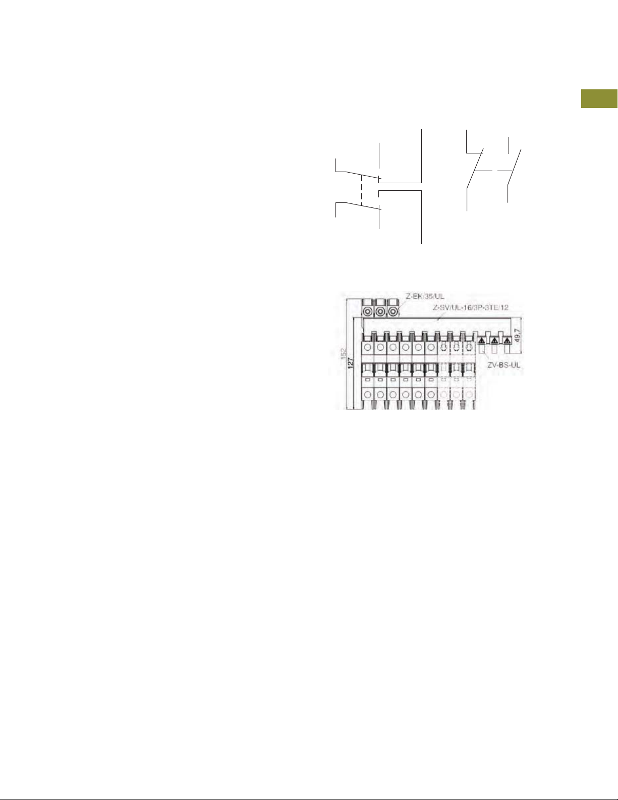
Miniature Circuit Breakers and Supplementary Protectors
UL 489 DIN Rail Miniature Circuit Breakers
1.2
Tripping Signal Switch Z-NHK, Z-IHK-NA
●
Design according to IEC/EN 60947-5-1, IEC/EN 62019
●
Field installable
●
The specified minimum voltages are per contact—take into
account particularly in case of series connection
●
Self-cleaning contacts
●
Contact material and design particularly suitable for extra
low voltage
●
Z-NHK: the function of one of the two change-over
contacts can be switched from “auxiliary switch” to
“tripping signal switch”
●
Tripping signal contact transmits message of electric tripping,
not mechanical switch-off
●
Test key for contact function “electrical tripping”
●
Z-IHK-NA: will allow for > 480Y/277 Vac rating
Connection Diagram
Z-NHK
4.14/4.12
4.12/4.14
4.11
1. 11
1. 14
1. 12
Busbar Connection Example
Z-IHK-NA
21
22
Same Polarity
1
1
13
1
1
1
14
1
1
1
1
1
1
1
1
1
1
1
1
1
1
1
1
1
1
1
1
1
1
1
Volume 4—Circuit Protection CA08100005E—April 2019 V4-T1-63
1
1

1.2
Z-NHK
Z-IHK-NA
Miniature Circuit Breakers and Supplementary Protectors
UL 489 DIN Rail Miniature Circuit Breakers
1
1
1
1
1
1
1
1
1
1
1
1
1
1
1
1
1
1
1
Contact and Auxiliary Contact
Description Z-NHK Z-IHK-NA
Electrical
Contact function 2CO 1NO + 1NC
Rated voltage 230V 250V
Frequency 50/60 Hz 50/60 Hz
Rated current 2A 6A
Rated thermal current I
Utilization category AC13
Rated operational current I
Utilization category AC15
Rated operational current I
Utilization category DC12
Rated operational current I
Rated insulation voltage U
Minimum operational voltage per contact U
Minimum operational current I
Rated peak withstand voltage U
Conditional short-circuit current I
Max. backup fuse, overload and short circuit 6A gL —
Mechanical
Tripping indicator “electrical tripping” Blue/white —
Frame size 45 mm 45 mm
Device height 80 mm 80 mm
Device width 8.8 mm (0.5MU) 8.8 mm (0.5MU)
Mounting Onto switching device —
Degree of protection, built-in IP40 IP40
Terminal protection Finger and hand touch safe
Terminals Lift terminals Lift terminals
Terminal capacity 20–14 AWG 0.5–2.5 mm
Terminal screws M3 (Posidrive Z0) M3 (Posidrive Z0)
Fastening torque of terminal screws 7 lb-in Max. 1.2 Nm
th
e
e
e
I
min
min
(1.2/50µ) 2.5 kV 4 kV
imp
with backup fuse 6A 1 kA 1 kA
k
2A 6A
3A/250 Vac 3A/250 Vac
2A/250 Vac 2A/250 Vac
0.5A/110 Vdc 0.5A/110 Vdc
250 Vac 250 Vac
5 Vdc 5 Vdc
10 mA DC 10 mA AC/DC
According to BGV A3, ÖVE-EN 6
0.25A/220 Vdc
Finger and hand touch safe
According to BGV A3, ÖVE-EN 6
2
1
1
1
1
1
1
1
1
1
1
1
V4-T1-64 Volume 4—Circuit Protection CA08100005E—April 2019

Miniature Circuit Breakers and Supplementary Protectors
Connection Diagram
1
2
Connection Diagrams
Single-Pole Busbar
UL 489 DIN Rail Miniature Circuit Breakers
1.2
Shunt trip release FAZ-XAA-NA
●
Remote release for subsequent mounting onto FAZ-NA/RT
●
Additional installation of standard auxiliary switch is possible
●
Position indicator red–green
Shunt Trip Release FAZ-XAA-NA
Description FAZ-XAA-NA12-110VAC FAZ-XAA-NA110-415VAC
Electrical
Can be
mounted onto
Operational
voltage range
Frequency 50/60 Hz 50/60 Hz
Mechanical
Frame size 45 mm 45 mm
Device height 105 mm 105 mm
Device width 17.5 mm 17.5 mm
Mounting Quick fastening with two lock-in positions on EN 50022
Degree of protection, built-in IP40 IP40
Terminal protection Finger and hand touch safe according to BGV A3, ÖVE-EN 6
Terminals Open mouthed/lift Open mouthed/lift
Terminal capacity
One and two wires
Busbar block UL 489 (pin)
●
Tested according to UL 489
●
Do not cut
●
Extension terminal 35 mm2 Z-EK/35/UL for copper conductors
●
Incoming terminal 50 mm2 Z-EB/50/UL
●
For covering of not used pins, use busbar tag shrouds ZV-BS-UL
Busbar Block UL 489 (Pin)
Three-Pole Busbar
Two-Pole Busbar
Description UL 489 IEC/EN 60947-2
Electrical
Rated operational voltage 480/277 Vac
Rated frequency 50/60 Hz —
Rated voltage 480 Vac 690 Vac
Overvoltage category — III
Rated impulse withstand voltage U
Rated current 80A at 40°C 80A at 30°C
Rated conditional short-circuit current AC with 350A gG — 15 kA
Short-circuit current 10 kA —
Mechanical
Busbar cross section — 16 mm
Flame class according to UL 94 V0 —
Pollution degree — 2
Comparative tracking index — CTI 600
Minimum clearance (internal/external) — > 9.5/25.4 mm
Minimum creepage distance (internal/external) — > 12.7/50.8 mm
Resistance to climatic conditions — According to
FAZ-NA / FAZ-NA-DC /
FAZ-RT
12–110 Vac
12–60 Vdc
18–10 AWG 18–10 AWG
96 Vdc
imp
—9.5 kV
FAZ-NA / FAZ-NA-DC /
FAZ-RT
110–415 Vac
110–230 Vdc
—
DIN/EN 60068
1
1
1
1
1
1
1
1
1
1
1
1
1
1
1
1
1
1
1
1
1
1
1
1
2
Cu
1
1
1
1
1
1
Volume 4—Circuit Protection CA08100005E—April 2019 V4-T1-65

1.2
Technical Data and Specifications
1
Trip Curve Chart
1
Eaton FAZ-NA and FAZ-NA-L
branch circuit breakers are
available with “B,” “C” and
1
“D” tripping characteristics.
B-curve devices are suitable
1
for applications where low
levels of inrush current
1
are expected.
C-curve devices are suitable
1
for applications where
medium levels of inrush
1
current are expected.
Applications include small
1
transformers, lighting, pilot
devices, control circuits and
coils. C-curve devices provide
1
a medium magnetic trip point.
1
1
Miniature Circuit Breakers and Supplementary Protectors
UL 489 DIN Rail Miniature Circuit Breakers
Tripping Characteristics
D-curve devices are suitable
for applications where high
levels of inrush current are
expected. The high magnetic
trip point prevents nuisance
tripping in high inductive
applications such as motors,
transformers and power
supplies.
Eaton FAZ-NA and FAZ-NA-L
devices are current limiting,
which means they interrupt
fault currents within one half
cycle of the fault. Current
limiting devices offer superior
protection by reducing peak
let-through current and
energy.
1
1
1
1
1
1
1
1
1
1
1
1
1
1
1
1
1
1
1
V4-T1-66 Volume 4—Circuit Protection CA08100005E—April 2019

Miniature Circuit Breakers and Supplementary Protectors
Two-Pole
Three-Pole
Connection Diagrams
Single-Pole
UL 489 DIN Rail Miniature Circuit Breakers
1.2
UL 489 Miniature Circuit Breakers Technical Data
Description FAZ-NA FAZ-NA-DC FAZ-NA-L
Electrical
Design according to UL 489, CSA C22.2 No.5, IEC 60947-2 UL 489, CSA C22.2 No.5, IEC 60947-2 UL 489, CSA C22.2 No.5, IEC 60947-2
Rated voltage Single-pole: 277 Vac
Rated current B: 1–32 A
Characteristic B, C, D C B, C, D
Current interrupting rating B curve—10 kA: 1–13 A, 30–32 A
Rated frequency 50/60 Hz 50/60 Hz 50/60 Hz
Endurance ≥ 20,000 operations ≥ 20,000 operations ≥ 20,000 operations
Line voltage connection Suitable for reverse feed Suitable for reverse feed Suitable for reverse feed
Mechanical
Frame size 45 mm 45 mm 45 mm
Device height 105 mm 105 mm 105 mm
Device width 17.7 mm per pole 17.7 mm per pole 17.7 mm per pole
Terminal protection Finger and hand touch safe according to
Mounting Quick fastening with two lock-in positions
Upper and lower terminals Open mouth/lift terminals Open mouth/lift terminals Open mouth/lift terminals
Terminal capacity One wire: AWG 18–6
Terminal fastening torque AWG 18–21: 21 lb-in
Mounting Independent of position Independent of position Independent of position
Calibration temperature
UL 489, CSA C22.2 No.5 40°C 40°C 40°C
IEC 60947-2 30°C 30°C 30°C
2-, 3- or 4-pole: 277/480 Vac
Single-pole: 48 Vdc per pole
2-pole in series: 96 Vdc
C & D: 0.5–32 A
C curve—10 kA: 0.5–13 A, 30–32 A
B & C curve—14 kA: 15–25 A
D curve—10 kA: 0.5–10 A, 25–32 A
D curve—14 kA: 13–20 A
BGV A3, OVE-EN 6
on IEC/EN 60715
Two wires: AWG 18–10
AWG 10–8: 25 lb-in
AWG 6: 36 lb-in
125 Vdc per pole
250 Vdc with 2-poles in connected series
— Single-pole: 48 Vdc per pole
C: 2–40 A B: 1–63 A
10 kA B curve—10 kA: 1–13 A, 30–32 A
Finger and hand touch safe according to
BGV A3, OVE-EN 6
Quick fastening with two lock-in positions
on IEC/EN 60715
One wire: AWG 18–6
Two wires: AWG 18–10
AWG 18–21: 21 lb-in
AWG 10–8: 25 lb-in
AWG 6: 36 lb-in
Single-pole: 240 Vac
2-, 3- or 4-pole: 240 Vac
2-pole in series: 96 Vdc
C: 0.5–63 A
D: 0.5–40 A
C curve—10 kA: 0.5–13 A, 30–32 A
B & C curve—14 kA: 15–25 A
D curve—10 kA: 0.5–10 A, 25–32 A
D curve—14 kA: 13–20 A
Finger and hand touch safe according to
BGV A3, OVE-EN 6
Quick fastening with two lock-in positions
on IEC/EN 60715
One wire: AWG 18–6
Two wires: AWG 18–10
AWG 18–21: 21 lb-in
AWG 10–8: 25 lb-in
AWG 6: 36 lb-in
1
1
1
1
1
1
1
1
1
1
1
1
1
1
1
1
1
1
1
1
1
1
1
1
1
1
1
1
1
1
Volume 4—Circuit Protection CA08100005E—April 2019 V4-T1-67

Miniature Circuit Breakers and Supplementary Protectors
1.2
Power Loss at ln
1
1
[A] P [W] P [W] P [W] P [W] P [W] P [W] P [W] P [W] P [W]
I
n
1
0.5
1.0
1
1.5
2.0
1
3.0
1
4.0
5.0
1
6.0
7.0
1
8.0
1
10.0
13.0
1
15.0
16.0
1
20.0
1
25.0
30.03.06.09.03.06.09.02.75.48.1
1
32.0 3.4 6.8 10.2 3.4 6.8 10.2 3.1 6.2 9.3
35.0 4.0 8.1 12.1 3.7 7.4 11.0 3.8 7.6 11.3
1
40.0 4.0 8.1 12.1 4.0 8.1 12.1 3.9 7.8 11.6
1
Characteristic B Characteristic C Characteristic D
Single-Pole Two-Pole Three-Pole Single-Pole Two-Pole Three-Pole Single-Pole Two-Pole Three-Pole
———
1.1 2.2 3.4
2.2 4.4 6.6
1.4 2.8 4.3
2.1 4.2 6.4
1.4 2.9 4.3
1.8 3.7 5.5
1.7 3.5 5.2
2.0 4.0 6.0
2.0 3.9 5.9
1.8 3.6 5.3
2.4 4.7 7.1
1.9 3.8 5.6
2.1 4.3 6.4
2.9 5.8 8.7
3.1 6.2 9.3
UL 489 DIN Rail Miniature Circuit Breakers
1.6 3.2 4.7 1.6 3.2 4.8
1.1 2.2 3.4 0.8 1.5 2.3
1.3 2.6 3.9 1.0 2.1 3.1
1.4 2.8 4.3 1.0 2.1 3.1
1.2 2.4 3.6 1.2 2.4 3.6
1.4 2.9 4.3 1.4 2.9 4.3
1.9 3.7 5.6 1.5 2.9 4.4
1.2 2.3 3.5 1.2 2.3 3.5
1.4 2.8 4.3 1.4 2.8 4.3
1.4 2.8 4.2 1.2 2.4 3.7
1.8 3.6 5.3 1.5 3.0 4.5
2.4 4.7 7.1 2.0 4.1 6.1
1.9 3.8 5.6 1.5 3.1 4.6
2.1 4.3 6.4 1.7 3.5 5.2
2.9 5.8 8.7 1.8 3.7 5.5
3.1 6.2 9.3 2.6 5.1 7.7
1
1
1
1
1
1
1
1
1
1
1
1
1
1
1
V4-T1-68 Volume 4—Circuit Protection CA08100005E—April 2019

Miniature Circuit Breakers and Supplementary Protectors
UL 489 DIN Rail Miniature Circuit Breakers
1.2
Let-Through Energy
Characteristic B (1–32A), 277V
Characteristic B (35–63A), 240V
1
1
1
1
1
1
1
1
1
1
1
1
1
1
Characteristic C (0.5–32A), 277V
1
1
Characteristic C (35–63A), 240V
1
1
1
1
1
1
1
1
1
1
1
1
Volume 4—Circuit Protection CA08100005E—April 2019 V4-T1-69
1
1

Miniature Circuit Breakers and Supplementary Protectors
1.2
Characteristic D (0.5–32A), 277V Characteristic D (35–63A), 240V
1
1
1
1
1
1
1
1
1
1
1
UL 489 DIN Rail Miniature Circuit Breakers
1
1
1
1
1
1
1
1
1
1
1
1
1
1
1
1
1
1
1
V4-T1-70 Volume 4—Circuit Protection CA08100005E—April 2019

Miniature Circuit Breakers and Supplementary Protectors
Ambient Temperature T [°C]
Maximum Load I
L
at ambient temperature T: IL (T) = IN KT(T)
Load Factor KT [I/I
N
]
Number of Circuit Breakers
Rated Diversity Factor
12345678
0.70
0.80
0.90
1. 00
UL 489 DIN Rail Miniature Circuit Breakers
1.2
Influence of Ambient Temperature T on Load Carrying Capacity
Device Market
Current Rating I
(A) at 40°C
0.50.60.50.50.50.50.50.50.5
1.01.11.11.11.01.01.00.90.9
1.51.71.61.61.61.51.41.41.4
2.02.22.22.12.12.01.91.91.8
3.03.33.23.23.13.02.92.92.8
4.04.44.34.24.24.03.83.83.7
5.05.55.45.35.25.04.84.74.6
6.06.66.56.46.26.05.85.65.5
7.07.77.67.47.37.06.76.66.4
8.08.88.68.58.38.07.77.57.4
10.0 11.0 10.8 10.6 10.4 10.0 9.6 9.4 9.2
13.0 14.3 14.0 13.8 13.5 13.0 12.5 12.5 12.0
15.0 16.5 16.2 15.9 15.6 15.0 14.4 14.1 13.8
16.0 17.6 17.3 17.0 16.6 16.0 15.4 15.0 14.7
20.0 22.0 21.6 21.2 20.8 20.0 19.2 18.8 18.4
25.0 27.5 27.0 26.5 26.0 25.0 24.0 23.3 23.0
30.0 33.0 32.4 31.8 31.2 30.0 28.8 28.2 27.6
32.0 35.2 34.6 33.9 33.3 32.0 30.7 30.1 29.4
40.0 44.0 43.2 42.4 41.6 40.0 38.4 37.6 36.8
(A) at Higher Ambient Temperature
I
n
n
15°C 20°C 25°C 30°C 40°C 50°C 55°C 60°C
Load Carrying Capacity of Adjoining Miniature
Circuit Breakers
1
1
1
1
1
1
1
1
1
1
1
1
1
1
1
1
1
1
1
1
1
1
1
1
1
1
1
1
1
Volume 4—Circuit Protection CA08100005E—April 2019 V4-T1-71
1

Miniature Circuit Breakers and Supplementary Protectors
H
Single-Pole Two-Pole Three-Pole
W1
W1
W2 W3
W1 W1
H H H
Four-Pole
W1
W1
W1
W4
Z-SV/UL-16/6
Z-SV/UL-18...12
ZV-BS-UL
1.2
Dimensions
1
Approximate Dimensions in Inches (mm)
Miniature Circuit Breakers
1
1
1
1
1
1
1
H W1W2W3W4
1
1
1
4.13
(105.0)
Accessories
0.70
(17.7)
UL 489 DIN Rail Miniature Circuit Breakers
1.39
(35.3)
2.09
(53.1)
2.79
(70.8)
Lockout Attachment— UL Lockoff Device—
Z-IS/SPE-1TE FAZPLOFF
MCB UL 489
1
1
1
1
1
1
Z-SV/UL-16.../18
1
1
1
1
1
1
Z-EK/35/UL
1
Description UL 489 IEC/EN 60947-2
U
e
1
f 50/60 Hz 50/60 Hz
U
1
imp
I
e
1
1
480 Vac/96 Vdc 240/415 Vac
—9.5 kV
80A at 40°C 80A at 30°C
10–1/0 AWG 60/75°C Cu 2.5–35 mm
0.56 in 14 mm
Z-EK/35/UL
Z-EB/50/UL
Description UL 489 IEC/EN 60947-2
U
e
f 50/60 Hz 50/60 Hz
U
imp
I
2
Cu
e
480 Vac/96 Vdc 240/415 Vac
—9.5 kV
115A at 40°C 160A at 30°C
#1–14 AWG 60/75°C Cu 1.5–50 mm
0.56 in 14 mm
2
Cu
1
1
V4-T1-72 Volume 4—Circuit Protection CA08100005E—April 2019

Miniature Circuit Breakers and Supplementary Protectors
Electronics
Internal Receptacle
UL 489
Breaker
UL 489
Branch
UL 1077
UL 1077
UL 1077
UL 489
Branch
UL 489
Branch
UL 489
Branch
External
Receptacle
External
Motor
M
M
External
Motor
Motor
Controller
Other
Sensitive
Devices
HACR
Example of UL 489 and UL 1077 Application
UL 489 DIN Rail Miniature Circuit Breakers
1.2
Application Guidelines
Example of UL 489 and UL 1077 Application
1
1
1
1
1
1
1
1
1
1
1
1
1
1
UL 489 circuit breakers
Used for branch circuit protection, internal/external receptacles, external motors and HACR equipment
(heating, air conditioning and refrigeration).
UL 1077 supplementary protectors
Used for overcurrent protection within appliances or electrical equipment, where branch circuit protection
is already provided or not required.
Note: UL 489 devices can be used in place of UL 1077; UL 1077 devices cannot be used in place of UL 489.
1
1
1
1
1
1
1
1
1
1
1
1
1
1
Volume 4—Circuit Protection CA08100005E—April 2019 V4-T1-73
1
1

1.3
FAZ Circuit Breakers
Miniature Circuit Breakers and Supplementary Protectors
UL 1077 DIN Rail Supplementary Protectors
1
1
1
1
1
1
Optimum and Efficient Protection for Every Application
1
1
1
1
1
FAZ Circuit Breakers
Product Overview
1
Optimum product quality,
tested reliability and safety
1
stand for best protection of
personnel, installations and
1
plant. Eaton’s FAZ DIN rail
mountable circuit breaker is
1
designed for use in control
panel applications.
1
Powerful offering for machine
and system builders
1
The FAZ is available with B,
C, D, K, S, and Z characteristics
1
in accordance with UL 1077,
CSA C22.2 No.235 and IEC
1
60947-2. These devices are
CE marked.
1
Application Description
●
1
1
1
Supplementary protection
●
Control circuits
●
Lighting
●
Business equipment
●
Appliances
Features
●
Complete range of UL
1077 recognized DIN
rail mounted miniature
circuit breakers up to
63A current rating
●
Standard ratings of 10 kAIC
up to 277/480 Vac
●
Current limiting design
provides fast short-circuit
interruption that reduces
the let-through energy,
which can damage
the circuit
●
Suitable for supplementary
protection
●
Thermal-magnetic
overcurrent protection
●
Six levels of short-circuit
protection, categorized
by B, C, D, K, S, and
Z curves
Contents
Description Page
FAZ Circuit Breakers. . . . . . . . . . . . . . . . . . . . . . . . V4-T1-74
Catalog Number Selection. . . . . . . . . . . . . . . . . . V4-T1-75
Standards and Certifications . . . . . . . . . . . . . . . . V4-T1-75
Product Selection . . . . . . . . . . . . . . . . . . . . . . . . V4-T1-76
Accessories . . . . . . . . . . . . . . . . . . . . . . . . . . . . . V4-T1-82
Technical Data and Specifications . . . . . . . . . . . . V4-T1-85
Dimensions . . . . . . . . . . . . . . . . . . . . . . . . . . . . . V4-T1-92
●
Trip-free design—breaker
can not be defeated by
holding the handle in the
ON position
●
Captive screws cannot
be lost
●
Fulfill UL 1077, CSA C22.2
No.235 and also IEC
60947-2 Standard
●
Field-installable shunt trip
and auxiliary switch
subsequent mounting
●
Module width of only
17.7 mm (per pole)
●
Contact position indicator
(red/green)
●
Easy installation on DIN rail
●
Possibility for sealing
the toggle in ON or
OFF position
1
1
1
1
1
1
1
V4-T1-74 Volume 4—Circuit Protection CA08100005E—April 2019
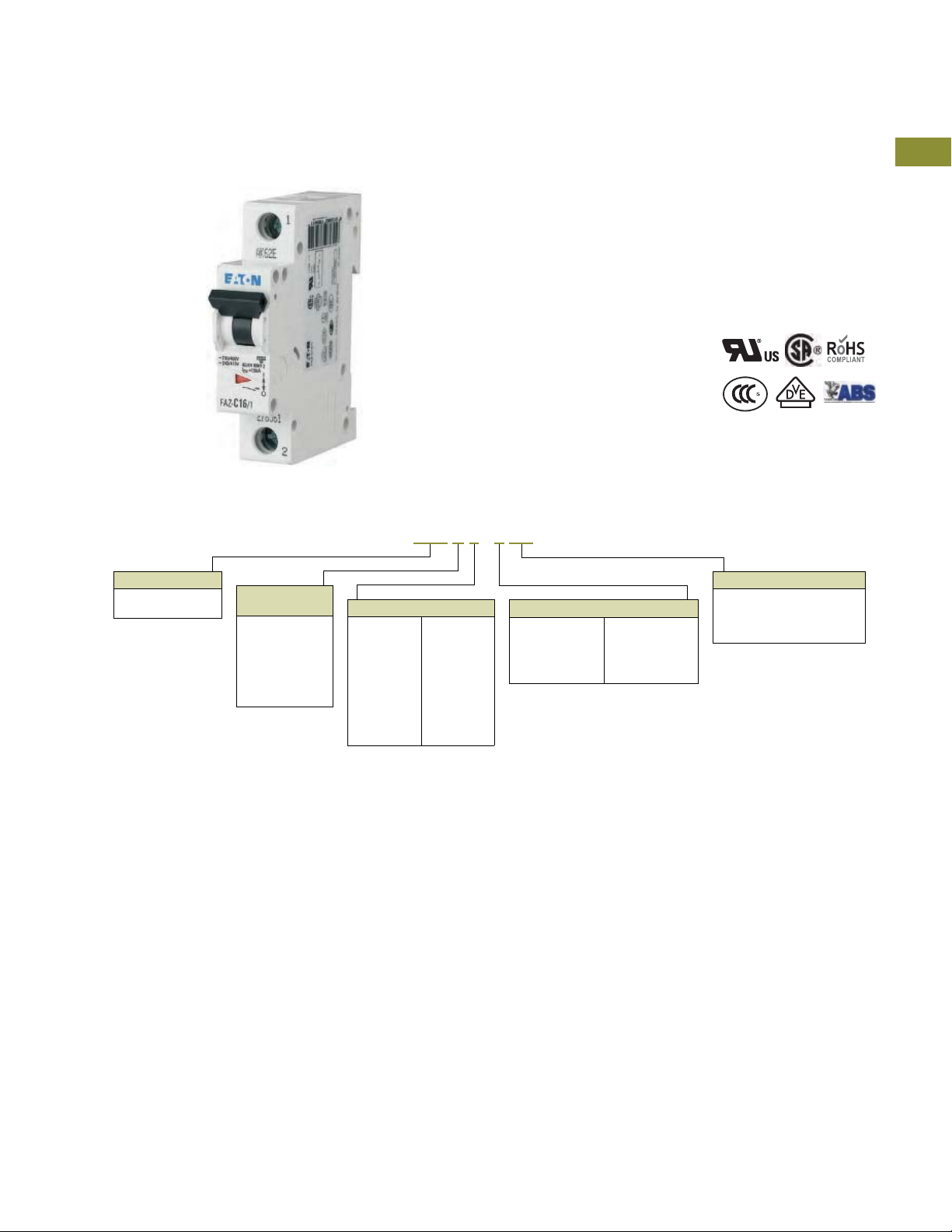
Miniature Circuit Breakers and Supplementary Protectors
Breakers install on
standard DIN rail
Available in one-, two-,
three-, four-pole, 1+N
and 3+N models
Color-coded indicator
provides breaker
status for easy
troubleshooting
Captive Posidrive
terminal screws with
finger a nd bac k-ofhand protection (IP20)
Trip -fr ee des ig n;
breaker cann ot be
defeated by holding
the handle in the
ON position
Breaker information
printed on the front of
the device for quick
identification
Breaker Family
FAZ = Supplementary
protector
Ampere Rating
0.5 =0.5A
1 =1A
2 =2A
3 =3A
4 =4A
5 =5A
6 =6A
7 =7A
8 =8A
10 =10A
13 = 13A
15 = 15A
16 = 16A
20 = 20A
25 = 25A
30 = 30A
32 = 32A
40 = 40A
50 = 50A
63 = 63A
Trip
Characteristics
1
B = 3–5X I
n
C = 5–10X I
n
D = 10–20X I
n
K = 8–12X I
n
S = 13–17X I
n
Z = 2–3X I
n
Number of Poles
1 = Single-pole
2 = Two-pole
3 = Three-pole
4 = Four-pole
1N = Single-pole +
neutral
3N = Three-pole +
neutral
Single Package
SP = Single packaging of single-
pole curve B, C and D for
select amperes only
Blank = Standard packaging
FAZ C 6 / 1 SP
UL 1077 DIN Rail Supplementary Protectors
1.3
Discover These Advanced Features
Catalog Number Selection
Standards and Certifications
FAZ complies with the latest
national and international
standards.
●
UL 1077, CSA C22.2
No. 235
●
Apply to supplementary
protectors intended for
use as overcurrent, or
overvoltage or
undervoltage protection
within an appliance or
other electrical
equipment where
branch circuit protection
is already provided, or is
not required
●
RoHS compliant
●
VDE compliant
●
Devices with B, C,
and D curves are
VDE compliant
●
CCC
●
Devices with B, C,
and D curves are
CCC compliant
●
ABS compliant
1
1
1
1
1
1
1
1
1
1
1
1
1
1
Note
1
In = Rated current for instantaneous trip characteristics.
Volume 4—Circuit Protection CA08100005E—April 2019 V4-T1-75
1
1
1
1
1
1
1
1
1
1
1
1
1
1
1
1

1.3
Single-Pole
Two -P ol e
Three-Pole
Four-Pole
Single-Pole + Neutral
Three-Pole + Neutral
Product Selection
1
FAZ B curve (3–5X In current rating)
●
1
●
1
●
●
1
●
Suitable for applications where protection against low-level
1
short-circuit faults in control wiring is desired. Instantaneous trip
is 3–5X continuous rating of device (I
1
wiring, business equipment, lighting, appliances and some
motors. Low magnetic trip point.
1
1
1
1
1
1
1
1
1
1
1
1
1
1
1
1
1
1
1
1
1
1
1
1
Miniature Circuit Breakers and Supplementary Protectors
UL 1077 DIN Rail Supplementary Protectors
Designed for resistive or slightly inductive loads
Response time of instantaneous trip: 3–5X In current rating
UL recognized and CSA Certified as supplementary protectors
For international and domestic use (conform to IEC 60947-2)
UL file number 177451
). Applications include PLC
n
B Curve (3–5X I
Designed for Resistive or Slightly
Inductive Loads
Single-Pole 2Two-Pole Three-Pole
Amperes
1 FAZ-B1/1-SP FAZ-B1/2 FAZ-B1/3
2 FAZ-B2/1-SP FAZ-B2/2 FAZ-B2/3
3 FAZ-B3/1-SP FAZ-B3/2 FAZ-B3/3
4 FAZ-B4/1-SP FAZ-B4/2 FAZ-B4/3
5 FAZ-B5/1-SP FAZ-B5/2 FAZ-B5/3
6 FAZ-B6/1-SP FAZ-B6/2 FAZ-B6/3
7 FAZ-B7/1-SP FAZ-B7/2 FAZ-B7/3
8 FAZ-B8/1-SP FAZ-B8/2 FAZ-B8/3
10 FAZ-B10/1-SP FAZ-B10/2 FAZ-B10/3
12 FAZ-B12/1-SP FAZ-B12/2 FAZ-B12/3
13 FAZ-B13/1-SP FAZ-B13/2 FAZ-B13/3
15 FAZ-B15/1-SP FAZ-B15/2 FAZ-B15/3
16 FAZ-B16/1-SP FAZ-B16/2 FAZ-B16/3
20 FAZ-B20/1-SP FAZ-B20/2 FAZ-B20/3
25 FAZ-B25/1-SP FAZ-B25/2 FAZ-B25/3
30 FAZ-B30/1-SP FAZ-B30/2 FAZ-B30/3
32 FAZ-B32/1-SP FAZ-B32/2 FAZ-B32/3
40 FAZ-B40/1-SP FAZ-B40/2 FAZ-B40/3
50 FAZ-B50/1-SP FAZ-B50/2 FAZ-B50/3
63 FAZ-B63/1-SP FAZ-B63/2 FAZ-B63/3
Notes
1
2
Catalog
Number
In North America, these switches are UL recognized and CSA Certified as supplementary protection devices. Per the intent of NEC (National Electrical Code), Article 240,
and CEC (Canadian Electrical Code), Part 1 C22.1, supplementary breakers cannot be used as a substitute for the branch circuit protective device. They can be used to
provide overcurrent protection within an appliance or other electrical equipment where branch circuit overcurrent protection is already provided, or is not required.
Option for single packaging on single-pole B, C and D curves only; add suffix SP when ordering.
Current Rating)—
n
1
Catalog
Number
Catalog
Number
7200
3600
1200
t [sec]
0.05
0.02
0.01
0.005
0.002
0.001
0.0005
1.13
1.45
Specied non-tripping
current
= 1.13 x IN for t > 1 h
I
600
300
120
60
30
10
5
2
1
0.5
0.2
0.1
1
NT
Specied tripping current
= 1.45 x IN for t < 1 h
I
T
1
1
2
B
3
I / I
B Curve (3–5X I
Designed for Resistive or Slightly
Inductive Loads, continued
Four-Pole
Amperes
1 FAZ-B1/4 FAZ-B1/1N FAZ-B1/3N
2 FAZ-B2/4 FAZ-B2/1N FAZ-B2/3N
3 FAZ-B3/4 FAZ-B3/1N FAZ-B3/3N
4 FAZ-B4/4 FAZ-B4/1N FAZ-B4/3N
5 FAZ-B5/4 FAZ-B5/1N FAZ-B5/3N
6 FAZ-B6/4 FAZ-B6/1N FAZ-B6/3N
7 FAZ-B7/4 FAZ-B7/1N FAZ-B7/3N
8 FAZ-B8/4 FAZ-B8/1N FAZ-B8/3N
10 FAZ-B10/4 FAZ-B10/1N FAZ-B10/3N
12 FAZ-B12/4 FAZ-B12/1N FAZ-B12/3N
13 FAZ-B13/4 FAZ-B13/1N FAZ-B13/3N
15 FAZ-B15/4 FAZ-B15/1N FAZ-B15/3N
16 FAZ-B16/4 FAZ-B16/1N FAZ-B16/3N
20 FAZ-B20/4 FAZ-B20/1N FAZ-B20/3N
25 FAZ-B25/4 FAZ-B25/1N FAZ-B25/3N
30 FAZ-B30/4 FAZ-B30/1N FAZ-B30/3N
32 FAZ-B32/4 FAZ-B32/1N FAZ-B32/3N
40 FAZ-B40/4 FAZ-B40/1N FAZ-B40/3N
50 FAZ-B50/4 FAZ-B50/1N FAZ-B50/3N
63 FAZ-B63/4 FAZ-B63/1N FAZ-B63/3N
Catalog
Number
2.55 IN:
t = 1–60 s (I
t = 1–120 s (I
Type B: 3 x IN: t > 0.1 s
Type B: 5 x IN: t < 0.1 s
1098765432
N
Current Rating)—
n
Single-Pole
+ Neutral
Catalog
Number
< 32A)
N
N
> 32A)
5040302015
1
Three-Pole
+ Neutral
Catalog
Number
V4-T1-76 Volume 4—Circuit Protection CA08100005E—April 2019
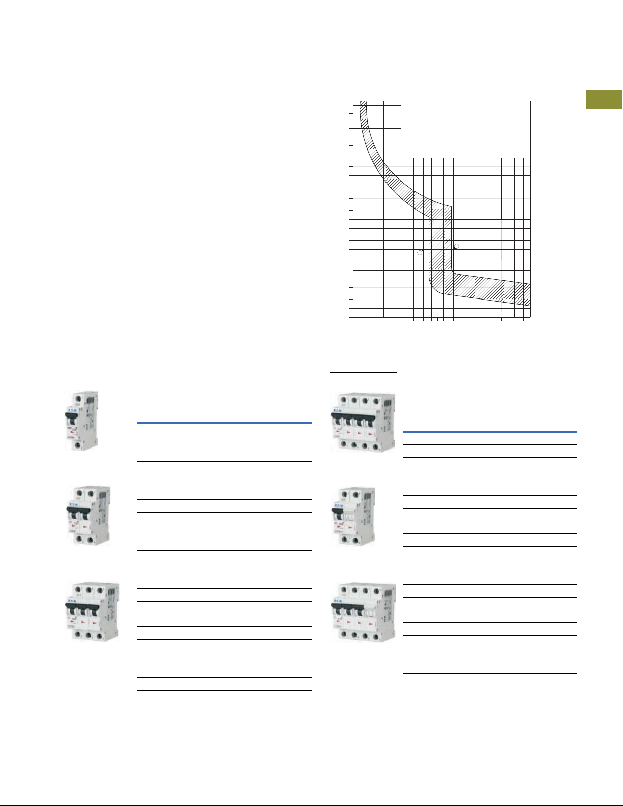
Miniature Circuit Breakers and Supplementary Protectors
Single-Pole
Two -P ol e
Three-Pole
Four-Pole
Single-Pole + Neutral
Three-Pole + Neutral
UL 1077 DIN Rail Supplementary Protectors
1.3
FAZ C curve (5–10X In current rating)
●
Designed for inductive loads
●
Response time of instantaneous trip: 5–10X In current rating
●
UL recognized and CSA Certified as supplementary protectors
●
For international and domestic use (conform to IEC 60947-2)
●
UL file number 177451
Suitable for applications where medium levels of inrush current
are expected. Instantaneous trip is 5–10X rating of device (I
Applications include small transformers, lighting, pilot devices,
).
n
control circuits and coils. Medium magnetic trip point.
C Curve (5–10X I
Designed Inductive Loads
Single-Pole
Amperes
0.5 FAZ-C0.5/1-SP FAZ-C0.5/2 FAZ-C0.5/3
1 FAZ-C1/1-SP FAZ-C1/2 FAZ-C1/3
1.6 FAZ-C1.6/1-SP FAZ-C1.6/2 FAZ-C1.6/3
2 FAZ-C2/1-SP FAZ-C2/2 FAZ-C2/3
3 FAZ-C3/1-SP FAZ-C3/2 FAZ-C3/3
4 FAZ-C4/1-SP FAZ-C4/2 FAZ-C4/3
5 FAZ-C5/1-SP FAZ-C5/2 FAZ-C5/3
6 FAZ-C6/1-SP FAZ-C6/2 FAZ-C6/3
7 FAZ-C7/1-SP FAZ-C7/2 FAZ-C7/3
8 FAZ-C8/1-SP FAZ-C8/2 FAZ-C8/3
10 FAZ-C10/1-SP FAZ-C10/2 FAZ-C10/3
13 FAZ-C13/1-SP FAZ-C13/2 FAZ-C13/3
15 FAZ-C15/1-SP FAZ-C15/2 FAZ-C15/3
16 FAZ-C16/1-SP FAZ-C16/2 FAZ-C16/3
20 FAZ-C20/1-SP FAZ-C20/2 FAZ-C20/3
25 FAZ-C25/1-SP FAZ-C25/2 FAZ-C25/3
30 FAZ-C30/1-SP FAZ-C30/2 FAZ-C30/3
32 FAZ-C32/1-SP FAZ-C32/2 FAZ-C32/3
40 FAZ-C40/1-SP FAZ-C40/2 FAZ-C40/3
50 FAZ-C50/1-SP FAZ-C50/2 FAZ-C50/3
63 FAZ-C63/1-SP FAZ-C63/2 FAZ-C63/3
Notes
1
2
Catalog
Number
In North America, these switches are UL recognized and CSA Certified as supplementary protection devices. Per the intent of NEC (National Electrical Code), Article 240,
and CEC (Canadian Electrical Code), Part 1 C22.1, supplementary breakers cannot be used as a substitute for the branch circuit protective device. They can be used to
provide overcurrent protection within an appliance or other electrical equipment where branch circuit overcurrent protection is already provided, or is not required.
Option for single packaging on single-pole B, C and D curves only; add suffix SP when ordering.
Current Rating)—
n
2
1
Two-Pole Three-Pole
Catalog
Number
Catalog
Number
7200
3600
1200
600
300
120
t [sec]
0.05
0.02
0.01
0.005
0.002
0.001
0.0005
1.13
1.45
Specied non-tripping
current
= 1.13 x IN for t > 1 h
I
NT
Specied tripping current
= 1.45 x IN for t < 1 h
I
T
60
30
10
5
2
1
0.5
0.2
0.1
1
C
2
Type C: 5 x IN: t > 0.1 s
Type C: 10 x IN: t < 0.1 s
1
1
1
1
1
1
1
1
1
1
1
I / I
1098765432
N
5040302015
1
1
1
C Curve (5–10X I
Designed Inductive Loads, continued
Four-Pole
Amperes
0.5 FAZ-C0.5/4 FAZ-C0.5/1N FAZ-C0.5/3N
1 FAZ-C1/4 FAZ-C1/1N FAZ-C1/3N
1.6 FAZ-C1.6/4 FAZ-C1.6/1N FAZ-C1.6/3N
2 FAZ-C2/4 FAZ-C2/1N FAZ-C2/3N
3 FAZ-C3/4 FAZ-C3/1N FAZ-C3/3N
4 FAZ-C4/4 FAZ-C4/1N FAZ-C4/3N
5 FAZ-C5/4 FAZ-C5/1N FAZ-C5/3N
6 FAZ-C6/4 FAZ-C6/1N FAZ-C6/3N
7 FAZ-C7/4 FAZ-C7/1N FAZ-C7/3N
8 FAZ-C8/4 FAZ-C8/1N FAZ-C8/3N
10 FAZ-C10/4 FAZ-C10/1N FAZ-C10/3N
13 FAZ-C13/4 FAZ-C13/1N FAZ-C13/3N
15 FAZ-C15/4 FAZ-C15/1N FAZ-C15/3N
16 FAZ-C16/4 FAZ-C16/1N FAZ-C16/3N
20 FAZ-C20/4 FAZ-C20/1N FAZ-C20/3N
25 FAZ-C25/4 FAZ-C25/1N FAZ-C25/3N
32 FAZ-C32/4 FAZ-C32/1N FAZ-C32/3N
40 FAZ-C40/4 FAZ-C40/1N FAZ-C40/3N
50 FAZ-C50/4 FAZ-C50/1N FAZ-C50/3N
63 FAZ-C63/4 FAZ-C63/1N FAZ-C63/3N
Catalog
Number
Current Rating)—
n
Single-Pole
+ Neutral
Catalog
Number
Three-Pole
+ Neutral
Catalog
Number
1
1
1
1
1
1
1
1
1
1
1
1
1
1
1
1
1
1
Volume 4—Circuit Protection CA08100005E—April 2019 V4-T1-77

1.3
Single-Pole
Two -P ol e
Three-Pole
Four-Pole
Single-Pole + Neutral
Three-Pole + Neutral
Miniature Circuit Breakers and Supplementary Protectors
UL 1077 DIN Rail Supplementary Protectors
FAZ D curve (10–20X In current rating)
1
●
●
1
●
●
1
●
1
Suitable for applications where high levels of inrush current are
expected. Instantaneous trip is 10–20X rating of device (I
high magnetic trip point prevents nuisance tripping in high
1
inductive applications such as motors, transformers and
power supplies.
1
1
1
1
1
1
1
1
1
1
1
1
1
1
1
1
1
1
1
1
1
1
1
1
1
Designed for highly inductive loads
Response time of instantaneous trip: 10–20X In current rating
UL recognized and CSA Certified as supplementary protectors
For international and domestic use (conform to IEC 60947-2)
UL file number 177451
). The
n
D Curve (10–20X I
Designed for Inductive Loads
Single-Pole
Amperes
0.5 FAZ-D0.5/1-SP FAZ-D0.5/2 FAZ-D0.5/3
1 FAZ-D1/1-SP FAZ-D1/2 FAZ-D1/3
2 FAZ-D2/1-SP FAZ-D2/2 FAZ-D2/3
3 FAZ-D3/1-SP FAZ-D3/2 FAZ-D3/3
4 FAZ-D4/1-SP FAZ-D4/2 FAZ-D4/3
5 FAZ-D5/1-SP FAZ-D5/2 FAZ-D5/3
6 FAZ-D6/1-SP FAZ-D6/2 FAZ-D6/3
7 FAZ-D7/1-SP FAZ-D7/2 FAZ-D7/3
8 FAZ-D8/1-SP FAZ-D8/2 FAZ-D8/3
10 FAZ-D10/1-SP FAZ-D10/2 FAZ-D10/3
13 FAZ-D13/1-SP FAZ-D13/2 FAZ-D13/3
15 FAZ-D15/1-SP FAZ-D15/2 FAZ-D15/3
16 FAZ-D16/1-SP FAZ-D16/2 FAZ-D16/3
20 FAZ-D20/1-SP FAZ-D20/2 FAZ-D20/3
25 FAZ-D25/1-SP FAZ-D25/2 FAZ-D25/3
30 FAZ-D30/1-SP FAZ-D30/2 FAZ-D30/3
32 FAZ-D32/1-SP FAZ-D32/2 FAZ-D32/3
40 FAZ-D40/1-SP FAZ-D40/2 FAZ-D40/3
50
63
Notes
1
2
3
Catalog
Number
3
FAZ-D50/1-SP FAZ-D50/2 FAZ-D50/3
3
FAZ-D63/1-SP FAZ-D63/2 FAZ-D63/3
In North America, these switches are UL recognized and CSA Certified as supplementary protection devices. Per the intent of NEC (National Electrical Code), Article 240,
and CEC (Canadian Electrical Code), Part 1 C22.1, supplementary breakers cannot be used as a substitute for the branch circuit protective device. They can be used to
provide overcurrent protection within an appliance or other electrical equipment where branch circuit overcurrent protection is already provided, or is not required.
Option for single packaging on single-pole B, C and D curves only; add suffix SP when ordering.
IEC 60947-2 only.
Current Rating)—
n
2
Two-Pole Three-Pole
Catalog
Number
1
Catalog
Number
7200
3600
1200
t [sec]
0.05
0.02
0.01
0.005
0.002
0.001
0.0005
1.13
1.45
2
1098765432
N
2.55 IN:
< 32A)
t = 1–60 s (I
N
> 32A)
t = 1–120 s (I
N
Type D: 10 x IN: t > 0.1 s
Type D: 20 x IN: t < 0.1 s
3
D
Current Rating)—
n
Single-Pole
+ Neutral
Catalog
Number
5040302015
Three-Pole
+ Neutral
Catalog
Number
1
Specied non-tripping
current
= 1.13 x IN for t > 1 h
I
NT
600
300
120
60
30
10
5
2
1
0.5
0.2
0.1
1
Specied tripping current
= 1.45 x IN for t < 1 h
I
T
1
1
I / I
D Curve (10–20X I
Designed for Inductive Loads, continued
Four-Pole
Amperes
0.5 FAZ-D0.5/4 FAZ-D0.5/1N FAZ-D0.5/3N
1 FAZ-D1/4 FAZ-D1/1N FAZ-D1/3N
2 FAZ-D2/4 FAZ-D2/1N FAZ-D2/3N
3 FAZ-D3/4 FAZ-D3/1N FAZ-D3/3N
4 FAZ-D4/4 FAZ-D4/1N FAZ-D4/3N
5 FAZ-D5/4 FAZ-D5/1N FAZ-D5/3N
6 FAZ-D6/4 FAZ-D6/1N FAZ-D6/3N
7 FAZ-D7/4 FAZ-D7/1N FAZ-D7/3N
8 FAZ-D8/4 FAZ-D8/1N FAZ-D8/3N
10 FAZ-D10/4 FAZ-D10/1N FAZ-D10/3N
13 FAZ-D13/4 FAZ-D13/1N FAZ-D13/3N
15 FAZ-D15/4 FAZ-D15/1N FAZ-D15/3N
16 FAZ-D16/4 FAZ-D16/1N FAZ-D16/3N
20 FAZ-D20/4 FAZ-D20/1N FAZ-D20/3N
25 FAZ-D25/4 FAZ-D25/1N FAZ-D25/3N
30 FAZ-D30/4 FAZ-D30/1N FAZ-D30/3N
32 FAZ-D32/4 FAZ-D32/1N FAZ-D32/3N
40 FAZ-D40/4 FAZ-D40/1N FAZ-D40/3N
50
63
Catalog
Number
c
FAZ-D50/4 FAZ-D50/1N FAZ-D50/3N
c
FAZ-D63/4 FAZ-D63/1N FAZ-D63/3N
V4-T1-78 Volume 4—Circuit Protection CA08100005E—April 2019

Miniature Circuit Breakers and Supplementary Protectors
Single-Pole
Two -P ol e
Three-Pole
Specied
non-tripping current
I
nt
= 1.05 u I
n
for t > 1 h
Specied
tripping current
It = 1.30 u I
n
for t < 1 h
U-rated Current
1 2 3 4 5 6 7 8 9 10 15 20 30 40 50
7200
3600
1200
600
300
120
60
30
10
5
2
1
0.5
0.2
0.1
0.05
0.02
0.01
0.005
0.002
0.001
0.0005
t (sec)
1. 13
1.45
K
Four-Pole
Single-Pole + Neutral
Three-Pole + Neutral
UL 1077 DIN Rail Supplementary Protectors
1.3
FAZ K curve (8–12X In current rating)
●
Designed for motors, transformers and upstream electronics
●
Response time of instantaneous trip: 8–12X In current rating
●
UL recognized and CSA Certified as supplementary protectors
●
For international and domestic use (conform to IEC 60947-2)
●
UL file number 177451
Suitable for applications where medium levels of inrush current
are expected. Instantaneous trip is 8–12X rating of device (I
Applications include small transformers, lighting, pilot devices,
).
n
control circuits and coils. Medium magnetic trip point.
K Curve (8–12X I
Designed for Inductive Loads
Amperes
0.5 FAZ-K0.5/1 FAZ-K0.5/2 FAZ-K0.5/3
1 FAZ-K1/1 FAZ-K1/2 FAZ-K1/3
1.6 FAZ-K1.6/1 FAZ-K1.6/2 FAZ-K1.6/3
2 FAZ-K2/1 FAZ-K2/2 FAZ-K2/3
3 FAZ-K3/1 FAZ-K3/2 FAZ-K3/3
4 FAZ-K4/1 FAZ-K4/2 FAZ-K4/3
6 FAZ-K6/1 FAZ-K6/2 FAZ-K6/3
8 FAZ-K8/1 FAZ-K8/2 FAZ-K8/3
10 FAZ-K10/1 FAZ-K10/2 FAZ-K10/3
13 FAZ-K13/1 FAZ-K13/2 FAZ-K13/3
16 FAZ-K16/1 FAZ-K16/2 FAZ-K16/3
20 FAZ-K20/1 FAZ-K20/2 FAZ-K20/3
25 FAZ-K25/1 FAZ-K25/2 FAZ-K25/3
32 FAZ-K32/1 FAZ-K32/2 FAZ-K32/3
40 FAZ-K40/1 FAZ-K40/2 FAZ-K40/3
50 FAZ-K50/1 FAZ-K50/2 FAZ-K50/3
63 FAZ-K63/1 FAZ-K63/2 FAZ-K63/3
Notes
1
2
3
Single-Pole
Catalog
Number
In North America, these switches are UL recognized and CSA Certified as supplementary protection devices. Per the intent of NEC (National Electrical Code), Article 240,
and CEC (Canadian Electrical Code), Part 1 C22.1, supplementary breakers cannot be used as a substitute for the branch circuit protective device. They can be used to
provide overcurrent protection within an appliance or other electrical equipment where branch circuit overcurrent protection is already provided, or is not required.
These breakers are available by special order and may result in additional delivery time.
Two-piece box order, quantities of 2.
Current Rating)—
n
3
Two-Pole Three-Pole
Catalog
Number
12
Catalog
Number
Volume 4—Circuit Protection CA08100005E—April 2019 V4-T1-79
K Curve (8–12X I
Designed for Inductive Loads, continued
Four-Pole
Amperes
0.5 FAZ-K0.5/4 FAZ-K0.5/1N FAZ-K0.5/3N
1 FAZ-K1/4 FAZ-K1/1N FAZ-K1/3N
1.6 FAZ-K1.6/4 FAZ-K1.6/1N FAZ-K1.6/3N
2 FAZ-K2/4 FAZ-K2/1N FAZ-K2/3N
3 FAZ-K3/4 FAZ-K3/1N FAZ-K3/3N
4 FAZ-K4/4 FAZ-K4/1N FAZ-K4/3N
6 FAZ-K6/4 FAZ-K6/1N FAZ-K6/3N
8 FAZ-K8/4 FAZ-K8/1N FAZ-K8/3N
10 FAZ-K10/4 FAZ-K10/1N FAZ-K10/3N
13 FAZ-K13/4 FAZ-K13/1N FAZ-K13/3N
16 FAZ-K16/4 FAZ-K16/1N FAZ-K16/3N
20 FAZ-K20/4 FAZ-K20/1N FAZ-K20/3N
25 FAZ-K25/4 FAZ-K25/1N FAZ-K25/3N
32 FAZ-K32/4 FAZ-K32/1N FAZ-K32/3N
40 FAZ-K40/4 FAZ-K40/1N FAZ-K40/3N
50 FAZ-K50/4 FAZ-K50/1N FAZ-K50/3N
63 FAZ-K63/4 FAZ-K63/1N FAZ-K63/3N
Catalog
Number
Current Rating)—
n
Single-Pole
3
+ Neutral
Catalog
Number
Three-Pole
+ Neutral
Catalog
Number
12
1
1
1
1
1
1
1
1
1
1
1
1
1
1
1
1
1
1
1
1
1
1
1
1
1
1
1
1
1
1

Miniature Circuit Breakers and Supplementary Protectors
Single-Pole
Two -P ol e
Specied
non-tripping current
I
nt
= 1.05 u I
n
for t > 1 h
Specied
tripping current
It = 1.30 u I
n
for t < 1 h
U-rated Current
1 2 3 4 5 6 7 8 9 10 15 20 30 40 50
7200
3600
1200
600
300
120
60
30
10
5
2
1
0.5
0.2
0.1
0.05
0.02
0.01
0.005
0.002
0.001
0.0005
t (sec)
1.05
1.30
S
1.3
FAZ S curve (13–17X In current rating)
1
●
Designed for control circuits with high inrush
●
1
1
1
1
1
1
1
1
1
1
Response time of instantaneous trip: 13–17X In current rating
●
UL recognized and CSA Certified as supplementary protectors
●
For international and domestic use (conform to IEC 60947-2)
●
UL file number 177451
Suitable for applications where high levels of inrush current are
expected. Instantaneous trip is 13–17X rating of device (I
high magnetic trip point prevents nuisance tripping in high
inductive applications such as motors, transformers and
power supplies.
UL 1077 DIN Rail Supplementary Protectors
). The
n
1
1
1
1
1
1
1
1
1
1
1
1
1
1
1
1
1
1
1
S Curve (13–17X I
Designed for Inductive Loads
Single-Pole
Amperes
1 FAZ-S1/1 FAZ-S1/2
2 FAZ-S2/1 FAZ-S2/2
3 FAZ-S3/1 FAZ-S3/2
4 FAZ-S4/1 FAZ-S4/2
6 FAZ-S6/1 FAZ-S6/2
10 FAZ-S10/1 FAZ-S10/2
16 FAZ-S16/1 FAZ-S16/2
20 FAZ-S20/1 FAZ-S20/2
25 FAZ-S25/1 FAZ-S25/2
32 FAZ-S32/1 FAZ-S32/2
40 FAZ-S40/1 FAZ-S40/2
Notes
V4-T1-80 Volume 4—Circuit Protection CA08100005E—April 2019
1
In North America, these switches are UL recognized and CSA
Certified as supplementary protection devices. Per the intent of
NEC (National Electrical Code), Article 240, and CEC (Canadian
Electrical Code), Part 1 C22.1, supplementary breakers cannot be
used as a substitute for the branch circuit protective device.
They can be used to provide overcurrent protection within an
appliance or other electrical equipment where branch circuit
overcurrent protection is already provided, or is not required.
2
These breakers are available by special order and may result in
additional delivery time.
3
Two-piece box order, quantities of 2.
Catalog
Number
Current Rating)—
n
3
12
Two - Po le
Catalog
Number

Miniature Circuit Breakers and Supplementary Protectors
Single-Pole
Two -P ol e
U-rated Current
1 2 3 4 5 6 7 8 9 10 15 20 30 40 50
7200
3600
1200
600
300
120
60
30
10
5
2
1
0.5
0.2
0.1
0.05
0.02
0.01
0.005
0.002
0.001
0.0005
t (sec)
1.05
1.30
Specied
non-tripping current
I
nt
= 1.05 u I
n
for t > 1 h
Specied
tripping current
It = 1.30 u I
n
for t < 1 h
Z
Four-Pole
Three-Pole
UL 1077 DIN Rail Supplementary Protectors
1.3
FAZ Z curve (2–3X In current rating)
●
Designed for protection of electronic devices
●
Response time of instantaneous trip: 2–3X In current rating
●
UL recognized and CSA Certified as supplementary protectors
●
For international and domestic use (conform to IEC 60947-2)
Suitable for applications where low levels of inrush current
are expected. Instantaneous trip is 2–3X rating of device (I
Applications include small transformers, lighting, pilot devices,
control circuits and coils. Medium magnetic trip point.
Z Curve (2–3X I
Designed for Inductive Loads
Single-Pole
Amperes
0.5 FAZ-Z0.5/1 FAZ-Z0.5/2
1 FAZ-Z1/1 FAZ-Z1/2
1.6 FAZ-Z1.6/1 FAZ-Z1.6/2
2 FAZ-Z2/1 FAZ-Z2/2
3 FAZ-Z3/1 FAZ-Z3/2
4 FAZ-Z4/1 FAZ-Z4/2
6 FAZ-Z6/1 FAZ-Z6/2
8 FAZ-Z8/1 FAZ-Z8/2
10 FAZ-Z10/1 FAZ-Z10/2
13 FAZ-Z13/1 FAZ-Z13/2
16 FAZ-Z16/1 FAZ-Z16/2
20 FAZ-Z20/1 FAZ-Z20/2
25 FAZ-Z25/1 FAZ-Z25/2
32 FAZ-Z32/1 FAZ-Z32/2
40 FAZ-Z40/1 FAZ-Z40/2
50 FAZ-Z50/1 FAZ-Z50/2
63 FAZ-Z63/1 FAZ-Z63/2
Notes
1
In North America, these switches are UL recognized and CSA Certified as supplementary protection devices. Per the intent of NEC (National Electrical Code), Article 240,
and CEC (Canadian Electrical Code), Part 1 C22.1, supplementary breakers cannot be used as a substitute for the branch circuit protective device. They can be used to
provide overcurrent protection within an appliance or other electrical equipment where branch circuit overcurrent protection is already provided, or is not required.
2
These breakers are available by special order and may result in additional delivery time.
3
Two-piece box order, quantities of 2.
Catalog
Number
Current Rating)—
n
3
12
Two - Po le
Catalog
Number
).
n
Volume 4—Circuit Protection CA08100005E—April 2019 V4-T1-81
Z Curve (2–3X I
Designed for Inductive Loads, continued
Amperes
0.5 FAZ-Z0.5/3 FAZ-Z0.5/4
1 FAZ-Z1/3 FAZ-Z1/4
1.6 FAZ-Z1.6/3 FAZ-Z1.6/4
2 FAZ-Z2/3 FAZ-Z2/4
3 FAZ-Z3/3 FAZ-Z3/4
4 FAZ-Z4/3 FAZ-Z4/4
6 FAZ-Z6/3 FAZ-Z6/4
8 FAZ-Z8/3 FAZ-Z8/4
10 FAZ-Z10/3 FAZ-Z10/4
13 FAZ-Z13/3 FAZ-Z13/4
16 FAZ-Z16/3 FAZ-Z16/4
20 FAZ-Z20/3 FAZ-Z20/4
25 FAZ-Z25/3 FAZ-Z25/4
32 FAZ-Z32/3 FAZ-Z32/4
40 FAZ-Z40/3 FAZ-Z40/4
50 FAZ-Z50/3 FAZ-Z50/4
63 FAZ-Z63/3 FAZ-Z63/4
Current Rating)—
n
Three-Pole Four-Pole
Catalog
Number
Catalog
Number
12
1
1
1
1
1
1
1
1
1
1
1
1
1
1
1
1
1
1
1
1
1
1
1
1
1
1
1
1
1
1

Miniature Circuit Breakers and Supplementary Protectors
C2
C1
AUX
TRIP
AUX AUX AUX
TRIP
FAZ FAZ FAZ
Circuit
Breaker
or
Circuit
Breaker
Shunt
Trip
or
Circuit
Breaker
UnderV
Trip
1.3
Accessories
1
FAZ Auxiliary Contacts and Voltage Trips
1
1
Standard Auxiliary Contacts
1
1
1
1
1
UL 1077 DIN Rail Supplementary Protectors
Circuit Diagram Description
■ 1NO/1NC
■ Installs on left side of FAZ or shunt trip
■ Max. one per FAZ (1077) device
■ Switches when FAZ is tripped
electrically or manually
14
12
■ 1 changeover contact
■ Installs on left side of FAZ or shunt trip
■ Max. one per FAZ (1077) device
■ Switches when FAZ is tripped
electrically or manually
Rated Operational
Voltage
230 Vac FAZ-XHIN11
230 Vac FAZ-XH INW1
Catalog
Number
1
Auxiliary/Trip Indicating Contact
1
1
1
1
1
1
1
Undervoltage Trip
1
1
1
1
1
Shunt Trip
1
1
1
11
Two-pole auxiliary mode
Trip indicating mode
D1
U
D2
■ Small selector screw changes mode
■ Two Form C (changeover) contacts
■ Installs on left side of FAZ or shunt trip
■ Auxiliary contacts switch when FAZ is
tripped electrically or manually
■ Trip indicating contact switches only
when FAZ is tripped electrically
■ Prevents FAZ from operating unless
voltage is present
■ Installs on left side of FAZ
■ Includes test button
■ Allows remote trip of FAZ
■ Installs on left side of FAZ
230 Vac FAZ-XAM002
115 Vac FAZ-XUA(115VAC)
230 Vac FAZ-XUA(230VAC)
400 Vac FAZ-XUA(400VAC)
12–110 Vac
12–60 Vdc
110–415 Vac
110–230 Vdc
FAZ-XAA-C-12-110VAC
FAZ-XAA-C-110415VAC
1
1
Allowable Combinations of Accessories
1
1
1
1
V4-T1-82 Volume 4—Circuit Protection CA08100005E—April 2019

Miniature Circuit Breakers and Supplementary Protectors
FAZ FAZ FAZ
FAZFAZ
UL 1077 DIN Rail Supplementary Protectors
1.3
Busbar System
Description Rated Operational Current
Without Auxiliary Contacts
For connecting FAZ supplementary protectors without auxiliary
contacts. May be fed from line or load side.
Auxiliary/Trip Indicating Contacts
For connecting FAZ supplementary protectors with auxiliary
contacts. May be fed from line or load side.
80A 1 57 BB-UL-18/1P-1M/57
100A 1 57 BB-UL-25/1P-1M/57
80A 1 37 BB-UL-18/1P-1,5M/37
Number of Poles
per Device
256BB-UL-18/2P-2M/56
357BB-UL-18/3P-3M/57
256BB-UL-25/2P-2M/56
357BB-UL-25/3P-3M/57
246BB-UL-18/2P+AS-2,5M/46
Number of
Terminals
Catalog
Number
1
1
1
1
1
1
1
1
1
1
1
1
1
1
1
1
Note
1
Bus may be center fed for high current capacity.
348BB-UL-18/3P+AS-3,5M/48
100A 1 37 BB-UL-25/1P-1,5M/37
246BB-UL-25/2P+AS-2,5M/46
348BB-UL-25/3P+AS-3,5M/48
1
1
1
1
1
1
1
1
1
1
1
1
1
1
Volume 4—Circuit Protection CA08100005E—April 2019 V4-T1-83
1

1.3
Incoming Terminal
Incoming Terminal
Busbar Terminal Cover
Padlock Hasp
Lockoff Device
Incoming Terminal
Fork Connector
Miniature Circuit Breakers and Supplementary Protectors
UL 1077 DIN Rail Supplementary Protectors
1
1
1
1
1
1
1
1
1
1
1
1
1
1
Pin Type Incoming Supply Terminals
Description
■ Accommodates conductors
from 6–35 mm
■ 4–5.5 Nm/35–50 lb-in
■ Two- and three-pole
Pin Type Incoming Supply Terminals—
Single-Phase Only
Description
■ Accommodates conductors
from 6–35 mm
■ 4–5.5 Nm/35–50 lb-in
Protective Accessories
Description
For covering
unused terminals
2
/#10–2 AWG
2
/#10–2 AWG
Catalog
Number
BB-UL-TEP/35
Catalog
Number
BB-UL-TEPA/35
Catalog
Number
BB-IP/5
Bus Incoming Supply Terminals
Description
2
■ 50 mm
■ #14–1 AWG
■ 75 Deg wire
■ 115 A/Y, 480V UL
■ 160 A/Y 690V IEC
Busbar End Cap
Description Poles
■ Install after cutting busbar
■ Protects end of busbar
Catalog
Number
BB-UL-TE/50
2 and 3 BB-EV-EC/3
1 BB-UL-EC/1
Catalog
Number
1
1
1
1
1
1
1
1
1
1
1
1
1
1
UL lockoff device FAZPLOFF
■ Prevents reactivation of the device
during maintenance
■ Holds one padlock
Z-IS/SPE-1TE
1
1
V4-T1-84 Volume 4—Circuit Protection CA08100005E—April 2019

Miniature Circuit Breakers and Supplementary Protectors
I/I
n
ZBCKS
D
1 2 3 4 5 6 7 8 9 10 15 20 30 40 50
7200
3600
1200
600
300
120
60
30
10
5
2
1
0.5
0.2
0.1
0.05
0.02
0.01
0.005
0.002
0.001
0.0005
t (sec)
1.05
1.30
1.1 3
1.45
UL 1077 DIN Rail Supplementary Protectors
1.3
Technical Data and Specifications
Trip Curves Chart
Eaton FAZ supplementary
protectors are available with
six different tripping
characteristics, including
Type B, C, D, K, S and Z.
Definitions for each trip curve
are contained on the ordering
pages and can be used to
determine the optimal
characteristic for your
application. For example,
low-level short-circuit faults in
control wiring, such as PLCs,
are best protected by devices
with Type B trip characteristics
(3–5X continuous rating of the
device (I
).
n
Even though not required by
NEC or CEC for supplementary
protectors, Eaton’s FAZ
devices are current limiting,
which means that they
interrupt fault currents
within one half cycle. Current
limiting devices offer superior
protection by reducing
peak let-through current
and energy.
Tripping Characteristics
Time-current characteristic acc. to UL 1077
Conventional
non-tripping current
= 1.13 IN: t > 1 h
I
nt
Conventional tripping
current
= 1.45 IN: t < 1 h
I
t
2.55 IN:
t = 1–60 s (I
t = 1–120 s (I
Type B: 3 IN: t > 0.1 s
Type B: 5 IN: t < 0.1 s
Type C: 5 IN: t > 0.1 s
Type C: 10 IN: t < 0.1 s
Type D: 10 IN: t > 0.1 s
Type D: 20 IN: t < 0.1 s
< 32A)
N
N
< 32A)
1
1
1
1
1
1
1
1
1
1
1
1
1
1
1
1
1
1
1
1
1
1
1
1
1
1
1
1
1
1
Volume 4—Circuit Protection CA08100005E—April 2019 V4-T1-85

Miniature Circuit Breakers and Supplementary Protectors
1.3
FAZ Miniature Circuit Breakers Technical Data
1
Description B Curve C Curve D Curve
Electrical
1
Approvals UR (UL 1077), CSA (CSA 22.2 No. 235), CE
Standards IEC/EN 60947-2
1
Short-circuit trip response 3–5 I
1
Supplementary Protectors—UL/CSA
Current range 1–63A 0.5–63A 0.5–40A
1
Maximum voltage ratings—UL/CSA
Single-pole, single-pole + neutral
1
Two-, three-pole, four-pole and
1
1
1
1
1
1
1
1
1
1
1
1
1
1
1
1
1
1
1
1
1
1
1
three-pole + neutral
Two poles in series
Thermal tripping characteristics
Single-pole
Multi-pole
Short-circuit ratings (at max. voltage)
Single-pole
Two-, three-pole
Single-pole
Two poles in series
Miniature Circuit Breaker—IEC
Current range 1–63A 0.5–63A 0.5–63A
Maximum voltage ratings—IEC 68898-1
Single-pole
Two-, three-pole
Maximum voltage ratings—IEC 60947-2
Single-pole
Two-, three-pole
Two poles in series
Thermal tripping characteristics
Single-pole
Multi-pole
Interrupt ratings (at max. voltage)
IEC 60947-2
IEC 60898
Operational switching capacity
Max. backup fuse [gL/gG]
Rated impulse withstand—U
Rated insulation voltage—U
Environmental/General
Selectivity class
Lifespan (operations)
Shock (IEC 68-2-22)
Operating temperature range
Shipment and short-term storage
Housing material
Mechanical
Standard front dimension
Device height
Terminal protection
Mounting width per pole
Mounting
Degree of protection
Terminals top and bottom
Supply connection
Terminal capacity [mm
Tor qu e
Imperial torque
Thickness of busbar material
Mounting position
2
UL 1077 DIN Rail Supplementary Protectors
n
277 Vac
48 Vdc
480Y/277 Vac
96 Vdc
@ 40°C
1.35 x I
n
@ 40°C
1.45 x I
n
10 kA (5 kA for 40–63A device)
10 kA (5 kA for 40–63A device)
10 kA @ 48 Vdc
10 kA @ 96 Vdc
230 Vac
230/400 Vac
240 Vac
48 Vdc
240/415 Vac
96 Vdc
> 1 hour @ 1.05 x I
< 1 hour @ 1.3 x I
15 kA
10 kA
7.5 kA
125A
imp
i
]
4000 Vac
440 Vac
3
> 10,000 (1 operation = ON/OFF)
10g–120 ms
–40 to +167°F (–40 to +75°C)
–40 to +185°F (–40 to +85°C)
Nylon
80 mm
Finger and back-of-hand proof to IEC 536
17.5 mm
IEC/EN 60715 top-hat rail
IP20
Twin-purpose terminals
Line or load side
1 x 25 (AWG 4–18)/2 x 10 (AWG 8–18)
2.4 Nm
21 lb-in (AWG 18–12), 25 lb-in
(AWG 10–8), 36 lb-in (AWG 6–4)
0.8–2 mm
As required
n
n
5–10 I
n
277 Vac
48 Vdc
480Y/277 Vac
96 Vdc
1.35 x I
@ 40°C
n
@ 40°C
1.45 x I
n
10 kA (5 kA for 40–63A device)
10 kA (5 kA for 40–63A device)
10 kA @ 48 Vdc
10 kA @ 96 Vdc
230 Vac
230/400 Vac
240 Vac
48 Vdc
240/415 Vac
96 Vdc
> 1 hour @ 1.05 x I
< 1 hour @ 1.3 x I
15 kA
10 kA
7.5 kA
125A
4000 Vac
440 Vac
3
> 10,000 (1 operation = ON/OFF)
10g–120 ms
–40 to +167°F (–40 to +75°C)
–40 to +185°F (–40 to +85°C)
Nylon
80 mm
Finger and back-of-hand proof to IEC 536
17.5 mm
IEC/EN 60715 top-hat rail
IP20
Twin-purpose terminals
Line or load side
1 x 25 (AWG 4–18)/2 x 10 (AWG 8–18)
2.4 Nm
21 lb-in (AWG 18–12), 25 lb-in
(AWG 10–8), 36 lb-in (AWG 6–4)
0.8–2 mm
As required
n
n
10–20 I
n
277 Vac
48 Vdc
480Y/277 Vac
96 Vdc
1.35 x I
@ 40°C
n
@ 40°C
1.45 x I
n
5 kA
5 kA
10 kA @ 48 Vdc
10 kA @ 96 Vdc
230 Vac
230/400 Vac
240 Vac
48 Vdc
240/415 Vac
96 Vdc
> 1 hour @ 1.05 x I
< 1 hour @ 1.3 x I
15 kA (10 kA for 50 and 63A)
10 kA (50 and 63A not available)
7.5 kA
125A
4000 Vac
440 Vac
3
> 10,000 (1 operation = ON/OFF)
10g–120 ms
–40 to +167°F (–40 to +75°C)
–40 to +185°F (–40 to +85°C)
Nylon
80 mm
Finger and back-of-hand proof to IEC 536
17.5 mm
IEC/EN 60715 top-hat rail
IP20
Twin-purpose terminals
Line or load side
1 x 25 (AWG 4–18)/2 x 10 (AWG 8–18)
2.4 Nm
21 lb-in (AWG 18–12), 25 lb-in
(AWG 10–8), 36 lb-in (AWG 6–4)
0.8–2 mm
As required
n
n
1
V4-T1-86 Volume 4—Circuit Protection CA08100005E—April 2019

Miniature Circuit Breakers and Supplementary Protectors
UL 1077 DIN Rail Supplementary Protectors
1.3
FAZ Miniature Circuit Breakers Technical Data, continued
Description K Curve S Curve Z Curve
Electrical
Approvals UR (UL 1077), CSA (CSA 22.2 No. 235), CE
Standards IEC/EN 60947-2, E177451, 204453
Short-circuit trip response 8–12 I
Supplementary Protectors—UL/CSA
Current range 0.5–63A 0.5–40A 1–63A
Maximum voltage ratings—UL/CSA
Single-pole, single-pole + neutral
Two-, three-, four-pole and
three-pole + neutral
Two poles in series
Thermal tripping characteristics
Single-pole
Multi-pole
Short-circuit ratings (at max. voltage)
Single-pole
Single-pole + neutral
Two-, three-, four-pole
Two poles in series
Miniature Circuit Breaker—IEC
Current range 0.5–63A 0.5–40A 1–63A
Maximum voltage ratings—IEC 60947-2
Single-pole, single-pole + neutral
Two-, three-, four-pole,
three-pole + neutral
Thermal tripping characteristics
Single-pole
Multi-pole
Interrupt ratings (at max. voltage)
IEC 60947-2
Operational switching capacity
Max. backup fuse [gL/gG]
Rated impulse withstand—U
Rated insulation voltage—U
Environmental/General
Selectivity class
Lifespan (operations)
Shock (IEC 68-2-22)
Operating temperature range
Shipment and short-term storage
Housing material
Mechanical
Standard front dimension
Device height
Terminal protection
Mounting width per pole
Mounting
Degree of protection
Terminals top and bottom
Supply connection
Terminal capacity [mm
Tor qu e
Imperial torque
Thickness of busbar material
Mounting position
imp
i
2
]
n
277 Vac
48 Vdc
480Y/277 Vac
96 Vdc
@ 40°C
1.35 x I
n
@ 40°C
1.45 x I
n
5 kA @ 277 Vac
5 kA @ 277 Vac
5 kA @ 480Y/277 Vac
—
240 Vac
240/415 Vac
> 1 Hour @ 1.05 x I
< 1 Hour @ 1.3 x I
15 kA
7.5 kA
125A
4000 Vac
440 Vac
3
> 10,000 (1 operation = ON/OFF)
10g–120 ms
–40 to +167°F (–40 to +75°C)
–40 to +185°F (–40 to +85°C)
Nylon
80 mm
Finger and back-of-hand proof to IEC 536
17.7 mm
IEC/EN 60715 top-hat rail
IP20
Twin-purpose terminals
Line or load side
1 x 25 (AWG 4–18) / 2 x 10 (AWG 8–18)
2.4 Nm
21 lb-in (AWG 18–12), 25 lb-in
(AWG 10–8), 36 lb-in (AWG 6–4)
0.8–2 mm
As required
n
n
13–17 I
n
277 Vac
48 Vdc
480Y/277 Vac
96 Vdc
1.35 x I
@ 40°C
n
@ 40°C
1.45 x I
n
5 kA @ 277 Vac
5 kA @ 277 Vac
5 kA @ 480Y/277 Vac
—
240 Vac
240/415 Vac
> 1 Hour @ 1.05 x I
< 1 Hour @ 1.3 x I
10 kA
7.5 kA
125A
4000 Vac
440 Vac
3
> 10,000 (1 operation = ON/OFF)
10g–120 ms
–40 to +167°F (–40 to +75°C)
–40 to +185°F (–40 to +85°C)
Nylon
80 mm
Finger and back-of-hand proof to IEC 536
17.7 mm
IEC/EN 60715 top-hat rail
IP20
Twin-purpose terminals
Line or load side
1 x 25 (AWG 4–18) / 2 x 10 (AWG 8–18)
2.4 Nm
21 lb-in (AWG 18–12), 25 lb-in
(AWG 10–8), 36 lb-in (AWG 6–4)
0.8–2 mm
As required
n
n
2–3 I
277 Vac
48 Vdc
480Y/277 Vac
96 Vdc
1.35 x I
1.45 x I
5 kA @ 277 Vac
5 kA @ 277 Vac
5 kA @ 480Y/277 Vac
—
240 Vac
240/415 Vac
> 1 Hour @ 1.05 x I
< 1 Hour @ 1.3 x I
10 kA
7.5 kA
125A
4000 Vac
440 Vac
3
> 10,000 (1 operation = ON/OFF)
10g–120 ms
–40 to +167°F (–40 to +75°C)
–40 to +185°F (–40 to +85°C)
Nylon
80 mm
Finger and back-of-hand proof to IEC 536
17.7 mm
IEC/EN 60715 top-hat rail
IP20
Twin-purpose terminals
Line or load side
1 x 25 (AWG 4–18) / 2 x 10 (AWG 8–18)
2.4 Nm
21 lb-in (AWG 18–12), 25 lb-in
(AWG 10–8), 36 lb-in (AWG 6–4)
0.8–2 mm
As required
n
n
n
@ 40°C
@ 40°C
1
1
1
1
1
1
1
1
1
1
1
1
1
1
n
n
1
1
1
1
1
1
1
1
1
1
1
1
1
Volume 4—Circuit Protection CA08100005E—April 2019 V4-T1-87
1
1
1

1.3
2 A
1 A
0.5 A
10 A
13 A
16 A
20 A
25 A
32 A
40 A
50 A
63 A
4 A
3 A
6 A
0.5
1.5 1512345678910
10
3
10
4
10
5
8
6
4
2
1.5
8
6
4
2
8
6
4
3
1.5
∫i2dt
[A2s]
I
cc rms
[kA]
10 A
13 A
16 A
20 A
25 A
32 A
40 A
6 A
0.5
1.5 1512345678910
10
3
10
4
10
5
8
6
4
2
1.5
8
6
4
2
8
6
4
1.5
∫i2dt
[A2s]
I
cc rms
[kA]
63 A
40 A
50 A
32 A
20 A
25 A
16 A
13 A
10 A
6 A
4 A
3 A
2 A
1 A
0.5 A
0.5
1.5 1512345678910
10
3
10
4
9
8
7
6
5
4
3
2
1.5
5
2
l
D
I
cc rms
[kA]
40 A
32 A
20 A
25 A
16 A
13 A
10 A
6 A
0.5
1.5 1512345678910
10
3
10
4
9
8
7
6
5
4
3
2
1.5
5
2
l
D
[A]
I
cc rms
[kA]
Miniature Circuit Breakers and Supplementary Protectors
UL 1077 DIN Rail Supplementary Protectors
Let-Through Energy I2t
1
Characteristic B and C
1
1
1
1
1
1
1
1
1
1
1
1
1
Let-Through Energy I
D
Characteristic B and C
1
1
Characteristic D
Characteristic D
1
1
1
1
1
1
1
1
1
1
1
1
1
1
V4-T1-88 Volume 4—Circuit Protection CA08100005E—April 2019

Miniature Circuit Breakers and Supplementary Protectors
63 A
40 A
50 A
32 A
20 A
25 A
16 A
13 A
10 A
6 A
4 A
3 A
2 A
1 A
1.6 A
0.5 A
0.5
1.512345678910
10
3
10
4
8
6
4
3
2
1.5
5
l
D
[A]
I
cc rms
[kA]
63 A
40 A
50 A
32 A
20 A
25 A
16 A
10 A
6 A
8 A
4 A
3 A
2 A
1 A
1.6 A
0.5 A
0.5
1.512345678910
10
3
10
4
8
6
4
3
2
1.5
5
l
D
[A]
I
cc rms
[kA]
40 A
32 A
20 A
25 A
16 A
10 A
6 A
4 A
3 A
2 A
1 A
0.5 1.512345678910
10
3
10
4
8
6
4
3
2
1.5
5
l
D
I
cc rms
[kA]
UL 1077 DIN Rail Supplementary Protectors
1.3
Let-Through Energy I2t
Characteristic K
Characteristic S
1
1
1
1
1
1
1
1
1
1
1
1
1
1
1
1
Characteristic Z
1
1
1
1
1
1
1
1
1
1
1
1
1
1
Volume 4—Circuit Protection CA08100005E—April 2019 V4-T1-89

Miniature Circuit Breakers and Supplementary Protectors
1.3
Influence of the Ambient Temperature on the Thermal Tripping Behavior
1
Corrected values of the rated current dependent on the ambient temperature
UL 1077 DIN Rail Supplementary Protectors
1
In (A)
0.16 0.20 0.20 0.19 0.19 0.18 0.17 0.17 0.16 0.16 0.15 0.15 0.15 0.14 0.14 0.14 0.14 0.13
1
0.25 0.32 0.31 0.30 0.29 0.28 0.27 0.26 0.25 0.25 0.24 0.24 0.23 0.23 0.22 0.22 0.21 0.21
1
0.50 0.64 0.62 0.60 0.58 0.56 0.54 0.52 0.50 0.49 0.48 0.47 0.46 0.45 0.44 0.43 0.42 0.41
0.75 0.96 0.93 0.90 0.87 0.84 0.81 0.78 0.75 0.74 0.73 0.71 0.69 0.68 0.66 0.65 0.64 0.62
1
1.00 1.30 1.20 1.20 1.20 1.10 1.10 1.00 1.00 0.99 0.97 0.95 0.93 0.90 0.89 0.87 0.85 0.83
1.50 1.90 1.90 1.80 1.70 1.70 1.60 1.60 1.50 1.50 1.50 1.40 1.40 1.40 1.30 1.30 1.30 1.20
1
1.60 2.00 2.00 1.90 1.90 1.80 1.70 1.70 1.60 1.60 1.50 1.50 1.50 1.40 1.40 1.40 1.40 1.30
2.00 2.60 2.50 2.40 2.30 2.20 2.20 2.10 2.00 2.00 1.90 1.90 1.90 1.80 1.80 1.70 1.70 1.70
1
2.50 3.20 3.10 3.00 2.90 2.80 2.70 2.60 2.50 2.50 2.40 2.40 2.30 2.30 2.20 2.20 2.10 2.10
3.00 3.80 3.70 3.60 3.50 3.40 3.30 3.10 3.00 3.00 2.90 2.80 2.80 2.70 2.70 2.60 2.50 2.50
1
3.50 4.50 4.40 4.20 4.10 3.90 3.80 3.70 3.50 3.40 3.40 3.30 3.20 3.20 3.10 3.00 3.00 2.90
4.00 5.10 5.00 4.80 4.70 4.50 4.30 4.20 4.00 3.90 3.90 3.80 3.70 3.60 3.50 3.50 3.40 3.30
1
5.00 6.40 6.20 6.00 5.80 5.60 5.40 5.20 5.00 4.90 4.80 4.70 4.60 4.50 4.40 4.30 4.20 4.10
6.00 7.70 7.50 7.20 7.00 6.70 6.50 6.30 6.00 5.90 5.80 5.70 5.60 5.40 5.30 5.20 5.10 5.00
1
7.00 9.00 8.70 8.40 8.20 7.80 7.60 7.40 7.00 6.90 6.80 6.70 6.50 6.30 6.20 6.10 6.00 5.80
8.00 10.20 9.90 9.60 9.30 9.00 8.70 8.40 8.00 7.90 7.70 7.60 7.40 7.20 7.10 6.90 6.80 6.60
1
10.00 13.00 12.00 12.00 12.00 11.00 11.00 10.00 10.00 9.90 9.70 9.50 9.30 9.00 8.90 8.70 8.50 8.30
12.00 15.00 15.00 14.00 14.00 13.00 13.00 13.00 12.00 12.00 12.00 11.00 11.00 11.00 11.00 10.00 10.00 10.00
1
13.00 17.00 16.00 16.00 15.00 15.00 14.00 14.00 13.00 13.00 13.00 12.00 12.00 12.00 12.00 11.00 11.00 11.00
15.00 19.00 19.00 18.00 17.00 17.00 16.00 16.00 15.00 15.00 15.00 14.00 14.00 14.00 13.00 13.00 13.00 12.00
1
16.00 20.00 20.00 19.00 19.00 18.00 17.00 17.00 16.00 16.00 15.00 15.00 15.00 14.00 14.00 14.00 14.00 13.00
20.00 26.00 25.00 24.00 23.00 22.00 22.00 21.00 20.00 20.00 19.00 19.00 19.00 18.00 18.00 17.00 17.00 17.00
1
25.00 32.00 31.00 30.00 29.00 28.00 27.00 26.00 25.00 25.00 24.00 24.00 23.00 23.00 22.00 22.00 21.00 21.00
1
32.00 41.00 40.00 38.00 37.00 36.00 35.00 33.00 32.00 32.00 31.00 30.00 30.00 29.00 28.00 28.00 27.00 26.00
35.00 45.00 43.00 41.00 41.00 38.00 38.00 36.00 35.00 35.00 34.00 33.00 32.00 32.00 32.00 30.00 29.00 29.00
1
40.00 51.00 50.00 48.00 47.00 45.00 43.00 42.00 40.00 39.00 39.00 38.00 37.00 36.00 35.00 35.00 34.00 33.00
50.00 64.00 62.00 60.00 58.00 56.00 54.00 52.00 50.00 49.00 48.00 47.00 46.00 45.00 44.00 43.00 42.00 41.00
1
63.00 81.00 78.00 76.00 73.00 71.00 68.00 66.00 63.00 62.00 61.00 60.00 58.00 57.00 56.00 55.00 53.00 52.00
Ambient Temperature T
–40°C –30°C –20°C –10°C 0°C 10°C 20°C 30°C 35°C 40°C 45°C 50°C 55°C 60°C 65°C 70°C 75°C
1
Influence of the Mains Frequency
Influence of the mains frequency on the tripping behavior I
1
of the instantaneous release
1
(f)IMA (50 Hz) [%] 91 100 101 106 115 134 141
I
1
MA
1
Load Carrying Capacity of Adjoining Miniature Circuit Breakers
1
1. 00
Mains Frequency f [Hz]
16 2/3 50 60 100 200 300 400
1
1
0.90
1
1
1
1
0.80
Rated Diversity Factor
0.70
12345678
Number of Circuit Breakers
1
MA
V4-T1-90 Volume 4—Circuit Protection CA08100005E—April 2019

Miniature Circuit Breakers and Supplementary Protectors
UL 1077 DIN Rail Supplementary Protectors
1.3
Accessories Technical Data
Description
Electrical
Contact function 1A + 1B
Rated operational voltage U
Voltage range — 12–110 Vac
Voltage range — 110–415 Vac
Closing threshold [x U
Tripping threshold [x U
Rated frequency ƒ 50/60 Hz 50/60 Hz 50/60 Hz
General use (UL/CSA)
AC—230/240 Vac
DC—110/120 Vdc
Pilot duty A600/Q600 — —
Conventional free air thermal current I
Rated operational current
AC-13 I
e
AC-15 I
e
DC-13 I
e
Rated insulation voltage U
Minimum operating voltage per contract U
Rated impulse withstand voltage (1.2/50) U
Rated conditional short-circuit current with 6A backup fuse I
Max. admissible backup fuse 4A gL — —
Mechanical
Standard front dimension 45 mm 45 mm 45 mm
Device height 80 mm 80 mm 80 mm
Mounting width 8.8 mm 17.6 mm 17.8 mm
Mounting On MCB IEC/EN 60715 top-hat rail IEC/EN 60715 top-hat rail
Degree of protection enclosed
Terminal protection Protection against
Terminals Lift terminals Twin-purpose terminals Twin-purpose terminals
Terminal capacity
Solid
Flexible
Tightening torque of terminal screws 0.8–1.0 Nm (7–9 lb-in) 2.4 Nm (21 lb-in) 0.8 Nm (7 lb-in)
n
]——0.8
n
]——0.5
n
th
i
min
imp
SC
FAZ-XH IN
FAZ-XAM002 FAZ-XAA-C FAZ-XUA
2 C/O
250 Vac — 115 Vac
2/2A
0.5/0.5A
4A — —
3A (250 Vac)
2A (250 Vac)
0.5A (110 Vdc)
250 Vac — —
5 Vdc — —
2.5 kV — —
1 kA — —
IP40 IP40 IP40
electric shock to IEC 536
2
0.5–2.5 mm
2
0.5–2.5 mm
—
—
12–60 Vdc
110–230 Vdc
—
—
—
—
—
Protection against
electric shock to IEC 536
2
1–2.5 mm
2
1–2.5 mm
—
—
230 Vac
400 Vac
—
—
—
—
—
—
—
Protection against
electric shock to IEC 536
2 x (1–2.5) mm
2 x (1–2.5) mm
2
2
1
1
1
1
1
1
1
1
1
1
1
1
1
1
1
1
1
1
1
1
1
1
1
Volume 4—Circuit Protection CA08100005E—April 2019 V4-T1-91
1
1
1
1
1
1
1

Miniature Circuit Breakers and Supplementary Protectors
2.79
(70.8)
1.77
(45.0)
0.74
(9.4)
2.36
(60.0)
1. 73
(44.0)
0.22
(5.5)
2.09
(53.1)
1.40
(35.4)
0.70
(17.8)
3.15
(80.0)
0.35
(8.8)
3.15
(80.0)
1.77
(45.0)
2.36
(60.0)
1. 73
(44.0)
0.22
(5.5)
0.35
(8.8)
3.15
(80.0)
1.77
(45.0)
2.36
(60.0)
1. 73
(44.0)
0.22
(5.5)
0.70
(17.8)
3.15
(80.0)
1.03
(26.2)
1.20
(30.5)
0.39
(10.0)
1.77
(45.0)
2.36
(60.0)
1. 73
(44.0)
0.22
(5.5)
0.70
(17.8)
3.15
(80.0)
1.77
(45.0)
2.36
(60.0)
1. 73
(44.0)
0.22
(5.5)
1.3
Dimensions
1
Approximate Dimensions in Inches (mm)
1
Miniature Circuit Breakers
FAZ
1
1
1
1
1
1
1
1
Auxiliary Contacts
1
FAZ-XHI11 and FAZ-XH1NW1 FAZ-XAM002
1
UL 1077 DIN Rail Supplementary Protectors
1
1
1
1
1
1
1
Shunt Releases Undervoltage Releases
FAZ -XAA FAZ- XUA
1
1
1
1
1
1
1
1
1
1
1
V4-T1-92 Volume 4—Circuit Protection CA08100005E—April 2019

Miniature Circuit Breakers and Supplementary Protectors
UL 1077 DIN Rail Supplementary Protectors
1.3
Approximate Dimensions in Inches (mm)
Busbar and Accessory Weights and Dimensions
Unit Weight (kg) Length Width Height
0.29 39.72 (1009.0) 0.59 (15.0) 0.59 (15.0) BB-UL-18/1P-1M/57
0.64 39.02 (991.0) 0.87 (22.0) 1.46 (37.0) BB-UL-18/2P-2M/56
0.83 39.72 (1009.0) 0.87 (22.0) 1.46 (37.0) BB-UL-18/3P-3M/57
0.26 38.78 (985.0) 0.59 (15.0) 0.59 (15.0) BB-UL-18/1P-1.5M/37
0.63 39.72 (1009.0) 0.87 (22.0) 1.46 (37.0) BB-UL-18/2P+AS-2.5M/46
0.79 38.66 (982.0) 0.87 (22.0) 1.46 (37.0) BB-UL-18/3P+AS-3.5M/48
0.36 39.72 (1009.0) 0.59 (15.0) 0.59 (15.0) BB-UL-25/1P-1M/57
0.79 39.02 (991.0) 0.87 (22.0) 1.46 (37.0) BB-UL-25/2P-2M/56
1.04 39.72 (1009.0) 0.87 (22.0) 1.46 (37.0) BB-UL-25/3P-3M/57
0.31 38.78 (985.0) 0.59 (15.0) 0.59 (15.0) BB-UL-25/1P-1.5M/37
0.73 39.72 (1009.0) 0.87 (22.0) 1.46 (37.0) BB-UL-25/2P+AS-2.5M/46
0.97 38.66 (982.0) 0.87 (22.0) 1.46 (37.0) BB-UL-25/3P+AS-3.5M/48
0.03 2.36 (60.0) 0.67 (17.0) 1.14 (29.0) BB-UL-TEP/35
0.03 1.42 (36.0) 0.67 (17.0) 1.14 (29.0) BB-UL-TEPA/35
0.03 1.57 (40.0) 0.71 (18.0) 1.18 (30.0) BB-UL-TE/50
0.003 3.35 (85.0) 0.47 (12.0) 0.94 (24.0) BB-IP/5
0.001 0.55 (14.0) 0.20 (5.0) 0.39 (10.0) BB-EV-EC/3
0.001 0.94 (24.0) 0.87 (22.0) 0.39 (10.0) BB-UL-EC/1
Catalog
Number
1
1
1
1
1
1
1
1
1
1
1
1
1
1
L W
L1 L2 L1 L2 L1 L2 L1 L2 L1 L2 L1 L2
1
1
1
H
1
1
1
1
1
1
1
1
1
1
1
Volume 4—Circuit Protection CA08100005E—April 2019 V4-T1-93
1
1

1.4
UL 1053 DIN Rail RCCB
Miniature Circuit Breakers and Supplementary Protectors
UL 1053 DIN Rail RCCB
1
1
1
1
1
1
1
1
1
1
1
UL 1053 DIN Rail RCCB 480/277 Vac
Product Overview
1
Optimum product quality,
tested reliability and safety
1
stand for best protection of
installations and plant.
1
Eaton’s UL 1053 Residual
Current Circuit Breaker
1
(RCCB) is designed for use in
residual current applications.
1
Application Description
●
1
1
1
1
Motor control circuits
●
HVAC internal/external
equipment
●
PLCs
●
HMIs
●
Equipment protection
●
European housing
1
1
1
Features
●
Wide range of compact
RCCB types serving as
fault-current and additional
protection according to
UL 1053 and IEC/EN 61008
standards, suitable for
worldwide use
●
Type A or Type G/A (with
delay) protection available
●
Comprehensive range of
accessories
●
Real contact position
indicator
●
Fault current tripping
indicator
●
Transparent designation
plate
●
Trip-free design—RCCB
can not be defeated by
holding the handle in the
ON position
●
Captive screws cannot
be lost
Contents
Description Page
UL 1053 DIN Rail RCCB 480/277 Vac
Product Selection . . . . . . . . . . . . . . . . . . . . . . . V4-T1-95
Accessories. . . . . . . . . . . . . . . . . . . . . . . . . . . . V4-T1-96
Technical Data and Specifications. . . . . . . . . . . V4-T1-97
Dimensions . . . . . . . . . . . . . . . . . . . . . . . . . . . . V4-T1-98
UL 1053 DIN Rail RCCB 208Y/120 Vac . . . . . . . . . . . . V4-T1-100
Standards and Certifications
●
UL 1053
●
IEC/EN 61008
●
CSA
●
ÖVE
●
CE Marked
1
1
1
1
1
1
1
V4-T1-94 Volume 4—Circuit Protection CA08100005E—April 2019

Miniature Circuit Breakers and Supplementary Protectors
Two - Po l e
Four-Pole
Two - Po l e
Four-Pole
UL 1053 DIN Rail RCCB
1.4
Product Selection
UL 1053 RCCB 480Y/277V Type A
Conditionally Surge Current–Proof 250A, Sensitive to Residual Pulsating DC, Type A
Two - Po le
Amperes
25 30 167113 FRCmM-25/2/003-A-NA
40 30 167114 FRCmM-40/2/003-A-NA
63 30 167115 FRCmM-63/2/003-A-NA
Conditionally Surge Current–Proof 250A, Sensitive to Residual Pulsating DC, Type A
Four-Pole
Amperes
25 30 167125 FRCmM-25/4/003-A-NA
40 30 167102 FRCmM-40/4/003-A-NA
63 30 167103 FRCmM-63/4/003-A-NA
GF Sensitivity
(mA)
300 167116 FRCmM-25/2/03-A-NA
300 167117 FRCmM-40/2/03-A-NA
300 167118 FRCmM-63/2/03-A-NA
GF Sensitivity
(mA)
300 167104 FRCmM-25/4/03-A-NA
300 167105 FRCmM-40/4/03-A-NA
300 167106 FRCmM-63/4/03-A-NA
Catalog
Number
Catalog
Number
1
1
Designation
Designation
1
1
1
1
1
1
1
1
1
1
1
1
1
1
UL 1053 RCCB 480Y/277V Type G/A
Type G/A has a 10 ms delay.
Surge Current–Proof 3 kA, Sensitive to Residual Pulsating DC, Type G/A (ÖVE E 8601)
Two - Po le
Amperes
25 30 167119 FRCmM-25/2/003-G/A-NA
40 30 167120 FRCmM-40/2/003-G/A-NA
63 30 167121 FRCmM-63/2/003-G/A-NA
Surge Current–Proof 3 kA, Sensitive to Residual Pulsating DC, Type G/A (ÖVE E 8601)
Four-Pole
Amperes
25 30 167107 FRCmM-25/4/003-G/A-NA
40 30 167108 FRCmM-40/4/003-G/A-NA
63 30 167109 FRCmM-63/4/003-G/A-NA
Note
1
Has no thermal element; must be paired with FAZ-NA or FAZ per application.
GF Sensitivity
(mA)
300 167122 FRCmM-25/2/03-G/A-NA
300 167123 FRCmM-40/2/03-G/A-NA
300 167124 FRCmM-63/2/03-G/A-NA
GF Sensitivity
(mA)
300 167110 FRCmM-25/4/03-G/A-NA
300 167111 FRCmM-40/4/03-G/A-NA
300 167112 FRCmM-63/4/03-G/A-NA
Catalog
Number
Catalog
Number
1
1
Designation
Designation
1
1
1
1
1
1
1
1
1
1
1
1
1
1
1
1
Volume 4—Circuit Protection CA08100005E—April 2019 V4-T1-95

1
Contact
Padlock Hasp
Lockoff Device
1
1
1
1
1
1.4
Accessories
Miniature Circuit Breakers and Supplementary Protectors
UL 1053 DIN Rail RCCB
UL 1053 DIN Rail RCCB 480/277 Vac
Description Catalog Number
Two-pole contact or auxiliary
contact / trip indicating contact
Z-NHK
1
Description Catalog Number
Padlock hasp Z-IS/SPE-1TE
1
1
1
1
1
1
1
1
1
1
1
1
1
1
UL lockoff device FAZPLOFF
Note
1
Voltage of FAZ-NA circuit breaker is limited to 300V with this auxiliary contact installed.
1
1
1
1
1
1
1
1
1
1
V4-T1-96 Volume 4—Circuit Protection CA08100005E—April 2019

Miniature Circuit Breakers and Supplementary Protectors
UL 1053 DIN Rail RCCB
1.4
Technical Data and Specifications
●
Residual current devices
●
Has no thermal protection; must be paired with FAZ-NA
or FAZ per application
●
Captive screw terminals
●
Universal tripping signal switch, also suitable for Z-A; can be
mounted subsequently
●
Auxiliary switch Z-HK can be mounted subsequently
●
Red-green contact position indicator
●
White-blue tripping indicator
●
Delayed types recommended for use with standard
fluorescent tubes with or without electronical ballast
(30mA-RCD: 30 units per phase conductor,
100mA-RCD: 90 units per phase conductor)
●
The device functions irrespective of the position of installation
●
Tripping is line voltage-independent. Consequently, the RCD is
suitable for “fault current/residual current protection” and
“additional protection” within the meaning of the applicable
installation rules
●
Reverse-feed permitted
●
The four-pole device can also be used for two-pole
connection. For this purpose, use terminals 5-6 and N-N
●
The test key “T” must be pressed every month. The system
operator must be informed of this obligation and responsibility
in a way that can be proven (self-adhesive RCD-label enclosed)
●
Pressing the test key “T” serves the only purpose of function
testing the residual current device (RCD). This test does not
make earthing resistance measurement (RE) or proper
checking of the earth conductor condition redundant, which
must be performed separately
●
Ty p e -A : Protects against special forms of residual pulsating
DC that have not been smoothed
●
Ty p e -G / A : Additionally protects against special forms of
residual pulsating DC that have not been smoothed
UL 1053 DIN Rail RCCB Technical Data
Description Specification
Electrical According to IEC/EN 61008
Design according to IEC/EN 61008
ÖVE E 8601
Current test marks as printed onto the device
Tripping Type G 10 ms delay
Rated voltage U
Rated tripping current I
Sensitivity AC and pulsating DC
Rated insulation voltage U
Rated impulse withstand voltage U
Rated short-circuit capacity I
Maximum backup fuse Overload protection Short-circuit protection
= 25–40A 25A gG/gL 63A gG/gL
I
n
I
= 63A 40A gG/gL 63A gG/gL
n
Rated breaking capacity I
Rated fault breaking capacity I
In = 25–40A 500A
= 63A 630A
I
n
Voltage range of test button Two-pole 184–250V~
Endurance Electrical >4000 operating cycles
Overvoltage category III
230/400V, 50 Hz
n
30, 300 mA
n
440V
4 kV
imp
10 kA
m
Four-pole 184–440V~
Mechanical >20,000 operating cycles
m
i
nc
bzw.
UL 1053 DIN Rail RCCB Technical Data, continued
Description Specification
Electrical According to UL 1053
Design according to UL 1053
Current test marks as printed onto the device
Tripping Type G 8 ms delay
Rated voltage U
Pickup current 22, 200 mA
Sensitivity AC and pulsating DC
Overvoltage tested 530V
Rated impulse withstand voltage U
Rated short-circuit capacity I
Maximum backup fuse Overload protection Short-circuit protection
In = 25–40A 25A gG/gL 63A gG/gL
= 63A 40A gG/gL 63A gG/gL
I
n
Rated breaking capacity I
Rated fault breaking capacity I
In = 25–40A 500A
= 63A 630A
I
n
Voltage range of test button Two-pole 184–305V~
Endurance Electrical >4000 operating cycles
Mechanical
Frame size 45.0 mm
Device height 80.0 mm
Device width 35 mm (2TE), 70 mm (4TE)
Device width Quick fastening with two
Degree of protection, built-in IP40
Degree of protection in moisture-proof
enclosure
Upper and lower terminals Lift terminals
Terminal protection Finger and hand touch
Terminal capacity 1.5–35 mm
Busbar material thickness 0.8–2 mm
Tripping temperature –25°C to +60°C
Resistance to climatic conditions According to IEC 61008
Humidity 5–95%
480Y/277V, 60 Hz
n
4 kV
imp
5 kA according to CSA
nc
or
m
m
Four-pole 184–528V~
Mechanical >20,000 operating cycles
lock-in positions on DIN
rail IEC/EN 60715
IP54
safe BGV A3, ÖVE-EN 6
2
single-wire
2
multi-wire
2 x 16 mm
1
1
1
1
1
1
1
1
1
1
1
1
1
1
1
1
1
1
1
1
1
1
1
1
1
1
1
1
1
1
Volume 4—Circuit Protection CA08100005E—April 2019 V4-T1-97

Miniature Circuit Breakers and Supplementary Protectors
Four-Pole
2.76
(70.0)
3.15
(80.0)
1.20
(30.5)
0.22
(5.5)
0.18
(4.5)
1.77
(45.0)
0.41
(10.5)
1.73
(44.0)
2.36
(60.0)
1.4
Connection Diagram Impact of Ambient Temperature on the Maximum
1
1
1
T
1
1
1
1
1
1
Correct Connection
1
1
1
N
2
N
Two-Pole Four-Pole
UL 1053 DIN Rail RCCB
15
3N
T
26
4N
Permanent Current Allowed (A)
16A 25A 40A 63A
Tripping
Temperature
40°C 16 16 25 25 40 40 63 63
45°C 14 14 21 22 37 37 59 59
50°C 11 11 18 19 33 34 55 55
55°C 9 9 14 16 30 31 50 50
60°C
Notes
1
Do not use.
Please make sure that these values are not exceeded and that any upstream overload protection
switches off in time.
Two -
Four-
Two -
Pole
Pole
1
———26 27 4545
Pole
FourPole
Two Pole
FourPole
Two Pole
FourPole
1
1
1
1
1
1
3+N
(230/400V) IEC
(277/480V) UL
Dimensions
Approximate Dimensions in Inches (mm)
UL 1053 DIN Rail RCCB
1
1
1
1
1
1
1
1
1
(184–254 Vac Phase-Phase) IEC
(184–277 Vac Phase-Phase) UL
Three-phase load without NThree-phase load without N
(400 Vac Phase-Phase) IEC
(480 Vac Phase-Phase) UL
1+N
(230V) IEC
(277V) UL
1
1
1
1
V4-T1-98 Volume 4—Circuit Protection CA08100005E—April 2019

Miniature Circuit Breakers and Supplementary Protectors
UL 1053 DIN Rail RCCB
1.4
Accessories Technical Data
Description Z-NHK
Electrical
Contact function 2CO
Rated voltage 230V
Frequency 50/60 Hz
Rated current 2A
Rated thermal current I
Utilization category AC13
Rated operational current I
Utilization category AC15
Rated operational current I
Utilization category DC12
Rated operational current I
Rated insulation voltage U
Minimum operational voltage per contact U
Minimum operational current I
Rated peak withstand voltage U
Conditional short-circuit current I
Maximum backup fuse, overload and short circuit 6A gL
Mechanical
Tripping indicator “electrical tripping” Blue/white
Frame size 45 mm
Device height 80 mm
Device width 8.8 mm (0.5MU)
Mounting Onto switching device
Degree of protection, built-in IP40
Terminal protection Finger and hand touch safe
Terminals Lift terminals
Terminal capacity 20–14 AWG
Terminal screws M3 (Posidrive Z0)
Fastening torque of terminal screws 7 lb-in maximum
2A
th
3A/250 Vac
e
2A/250 Vac
e
0.5A/110 Vdc
e
250 Vac
I
min
imp
with backup fuse 6A 1 kA
k
5 Vdc
min
(1.2/50) 2.5 kV
10 mA DC
According to BGV A3, ÖVE-EN 6
1
1
1
1
1
1
1
1
1
1
1
1
1
1
1
1
1
1
1
1
1
1
1
1
1
1
1
1
1
1
Volume 4—Circuit Protection CA08100005E—April 2019 V4-T1-99
 Loading...