

Page 1
34-292
IEC Contactors & Starters
Miniature Controls
March 2008
Product Family Overview
34
Contents
Description Page
Product Family Overview
Product Description. . . . . . . 34-292
Features . . . . . . . . . . . . . . . . 34-292
Standards and
Certifications . . . . . . . . . . . 34-292
Instructional Leaflets . . . . . . 34-292
Catalog Number
Selection . . . . . . . . . . . . . . 34-293
Contactors — Non-reversing and
Reversing
Product Selection . . . . . . . . 34-294
Accessories
Auxiliary Contacts Front
and Side Mounted . . . . . . 34-295
Overload Relays. . . . . . . . . . 34-295
ID Markers, Reversing
Connection Links and
Surge Suppressors . . . . . . 34-296
Note: For more information, see
CA03402001E.
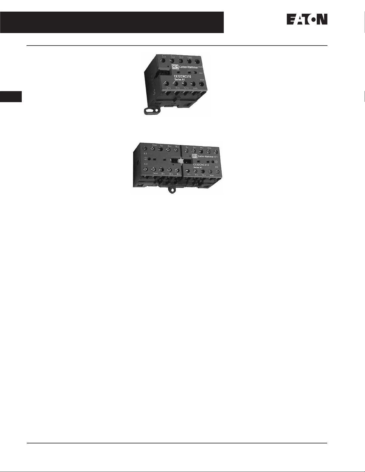
Mini Contactor with Screw
Pressure Plate Terminals
Catalog Number CE12BNC310B
Mini Contactor Reversing Pair with
Screw Pressure Plate Terminals
Catalog Number CE52CNC310H
Product Description
Eaton offers a complete line of CutlerHammer
that includes mini contactors (mechanically interlocked and non-reversing),
overload relays and snap-on accessories. A wide range of applications are
possible, including small electrical
motors fractional to 5 hp (480V AC).
Because of its compact size, the line is
best suited to be applied in light duty
loads such as hoisting, packaging,
material handling, heating, lighting
and automation systems.
®
Miniature Control Products
Overload Relays
(Bimetallic Type — C312)
■ 11 Settings — to cover .10 to 12.0
Amps
■ Phase loss compensated
■ Ambient temperature
compensated
■ Class 10 — Bimetallic type O.L.
■ Stop and test buttons included
■ 1NO-1NC auxiliary contacts
included as standard
Accessories
■ Side and front mounted auxiliary
contacts
■ Identification clips
■ Surge suppressors
■ Reversing connection links
Standards and Certifications
Meet or exceed the North American
and International standards:
■ UL
■ CSA
❑ Mini Contactors and Surge
Suppressors
UL File No. E19224, Category
NLDX and NLDX2; CSA File No.
LR353, Class 3211-07
❑ Accessories
UL File No. E19223, Category
NKCR and NKCR2; CSA File No.
LR353, Class 3211-07
❑ Overload Relays
UL File No. E19223, Category
NKCR and NKCR2; CSA File No.
LR353, Class 3211-03
■ IEC, VDE, CE and most other
International standards
Features
Mini Contactors
■ Available in three different
terminal configurations:
❑ Screw Pressure Plate
❑ Quick Connect
❑ Solder Pin
■ Mechanically interlocked or
non-reversing
■ Panel or DIN rail mounting (35 mm)
■ Fingerproof protection
■ Low noise operation
■ AC or DC operation possible
For more information visit: www.eaton.com CA08102001E
Instructional Leaflets
49097 Minicontactors, Overloads and
Accessories
Page 2
IEC Contactors & Starters
Miniature Controls
March 2008
Catalog Number Selection
Catalog Number Selection
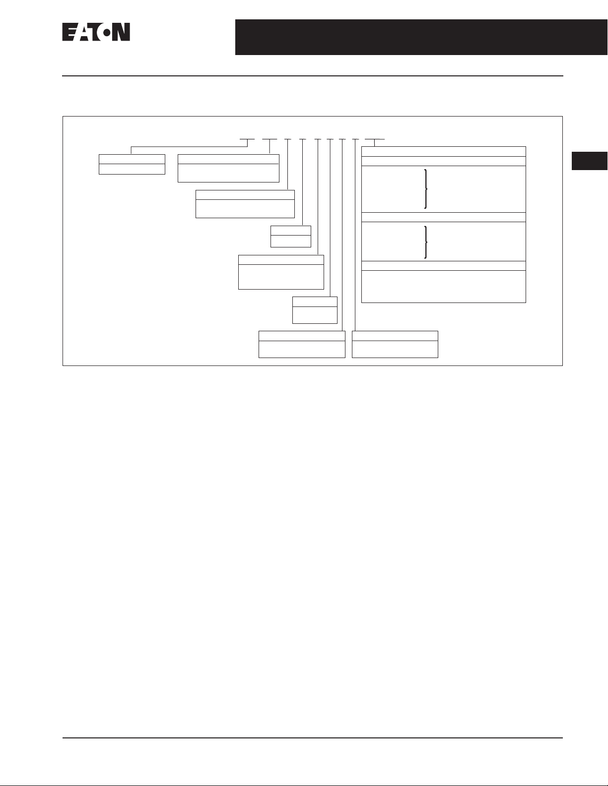
Table 34-360. IEC Miniature Controls Catalog Numbering System
C E 1 2 B N C 3 1 0 W 1
34-293
Designation
IEC Contactor
CE -
NOTE: No renewal parts (coils, contact kits)
available for the Mini Control line.
12 52 -
Typ e
Non-reversing
Mechanically Interlocked
4 kW (3 hp @460V AC)
B -
5.5 kW (5 hp @460V AC)
C -
Power
Enclosure
N -
Connections
Quick Connects
B -
Screw Pressure Plate
C -
Solder Pin
P -
No. of NO Aux. Contacts
None
0 -
One
1 -
Open
No. of Poles
3 Poles
3 -
4 Poles
4 -
Coil Designations
AC Coil Voltage (Frequency 40 – 450 Hz)
24V
T -
48V
W -
110 – 127V
A -
220 – 240V
B -
227V
H -
380 – 415V
L -
12V
R1 -
24V
T1 -
48V
W1 -
110 – 125V
A1 -
220 – 240V
B1 -
DC — Low Power Consumption Coils
24V (1.4 Watts)
T2 -
17 – 32V (2.4 Watts)
V2 -
24V (1.7 Watts with Surge Suppressor)
T3 -
17 – 32V (2.8 Watts with Surge Suppressor)
V3 -
No. of NC Aux. Contacts
None
0 -
One
1 -
3.5 VA
DC Coil Voltage
3.5 Watts
34
CA08102001E For more information visit: www.eaton.com
Page 3
34-294
34
IEC Contactors & Starters
Miniature Controls
March 2008
Contactors — Non-reversing and Reversing
Product Selection
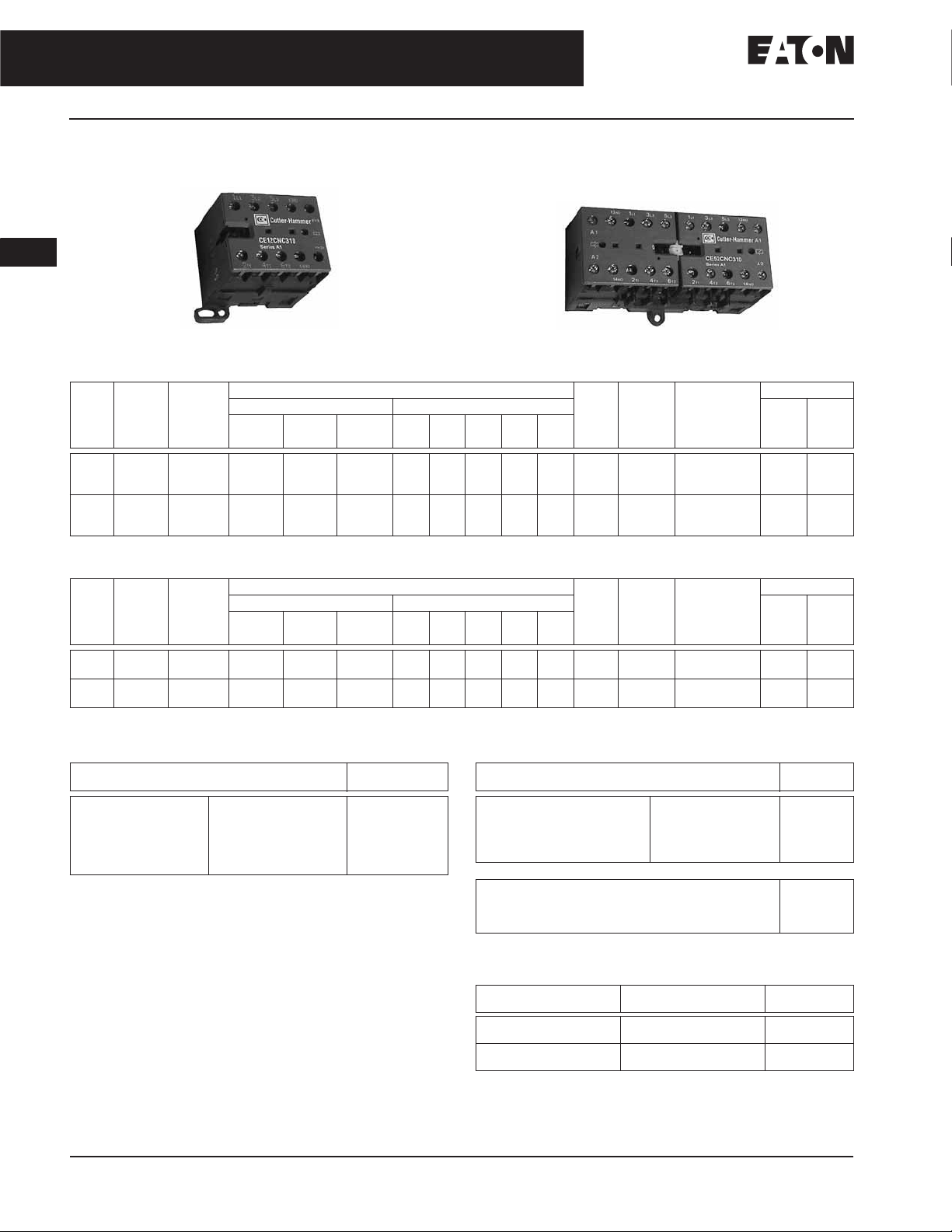
Non-reversing/Reversing Contactors with Screw Pressure Terminals
Screw Pressure Plate Terminals —
Non-reversing Contactor
Table 34-361. Non-reversing Contactor — Screw Pressure Plate Terminals
Max.
IEC 947
AC-3
AC-1
Amp
Thermal
Rating
Current
(400V)
(400V)
9
16
9
16
9
16
12
20
12
20
12
20
Quick Connect and Solder Pin Terminals are available. Insert a “B” into the seventh digit for Quick Connect or “P” for Solder Pin Terminal.
kW
Rating
AC-3
400/440V
4
4
4
5.5
5.5
5.5
Maximum UL Horsepower No. of
1-Phase Horsepower Ratings 3-Phase Horsepower Ratings AC
110/
120V
1/2
1/2
1/2
3/4
3/4
3/4
220/
240V
1
1
1
1-1/2
1-1/2
1-1/2
480/
600V
None
None
None
2
2
2
110/
120V
1
1
1
1
1
1
Table 34-362. Reversing Contactor — Screw Pressure Plate Terminals
Max.
IEC 947
AC-3
AC-1
Amp
Thermal
Rating
Current
(400V)
(400V)
9
16
9
16
12
20
12
20
Screw pressure plate terminal contactors are supplied standard with reversing connection links included. Quick Connect and Solder Pin Terminals are
available. Insert a “B” into the seventh digit for Quick Connect or “P” for Solder Pin Terminal.
kW
Rating
AC-3
400/440V
4
4
5.5
5.5
Maximum UL Horsepower No. of
1-Phase Horsepower Ratings 3-Phase Horsepower Ratings AC
110/
120V
1/2
1/2
3/4
3/4
220/
240V
1
1
1-1/2
1-1/222
480/
600V
None
None111122333333
110/
120V
11223355553
Table 34-363. AC Coil Selection Table
Coil Voltage Frequency
40 – 450 Hz
24
48
110 – 127
220 – 240
277
380 – 415
AC coils have an integrated protective circuit-rectifier bridge and
varistor included.
3.5 VA
3.5 VA
3.5 VA
3.5 VA
3.5 VA
3.5 VA
Suffix
Code
T
W
A
B
H
L
200/
220/
240V
2
2
2
3
3
3
220/
240V
440/
480V
3
3
3
5
5
5
440/
480V
208V
1
1
1
2
2
2
200/
208V
Table 34-364. DC Coil Selection Table
Coil Voltage Suffix
12
24
48
110 – 125
220 – 240
DC Low Power Consumption Coils: Non-reversing Mini Contactors
24 (1.4 Watts)
17 – 32 (2.4 Watts)
24 (1.7 Watts with Surge Suppressor)
17 – 32 (2.8 Watts with Surge Suppressor)
Auxiliary contacts can not be used with Low Power Consumption DC
Coils Suffix designations: T2, V2, T3 and V3.
Screw Pressure Plate Terminals —
Reversing Contactor
550/
600V
3
3
3
5
5
5
550/
600V
Power
Poles
3
3
4
3
3
4
Power
Poles
3
Aux.
Contacts
1NO
1NC
None
1NO
1NC
None
Aux.
Contacts
1NO
1NC
1NO
1NC
Catalog
Number
CE12BNC310_
CE12BNC301_
CE12BNC400_
CE12CNC310_
CE12CNC301_
CE12CNC400_
Catalog
Number
CE52BNC310_
CE52BNC301_
CE52CNC310_
CE52CNC301_
3.5 Watts
3.5 Watts
3.5 Watts
3.5 Watts
3.5 Watts
Price U.S. $
CoilDCCoil
Price U.S. $
CoilDCCoil
Code
R1
T1
W1
A1
B1
T2
V2
T3
V3
Table 34-365. Price Adder for Low Wattage DC Coils
Devices Suffix Designations Adder
4 kW T2 & V2
T3 & V3
5 kW T2 & V2
T3 & V3
U.S. $
Discount Symbol . . . . . . . . . . . . . . . . . . . . . . . . 1CD7
For more information visit: www.eaton.com CA08102001E
Page 4

March 2008
IEC Contactors & Starters
MMPs & Manual and Combination Motor Controllers
34-341
Types AM/AE317/357, AE318/358, AE319/359 Freedom IEC Combination Motor Controllers
Product Selection
AM317 — Miniature Freedom IEC
Open Non-reversing Combination
For use as CMCs in Group Installation
or UL 508 Type F applications.
When Ordering Specify —
■ Select required assembled motor
controller by Catalog Number from
Table 34-443 and replace underscore
(_) in the Catalog Number with the
proper Magnetic Coil Code Suffix
Letter from Table 34-444.
■ All Non-reversing and Reversing
motor controllers are selected based
on the overload current range
required for a given motor. This current range is determined from the
motor Full Load Ampere rating and
Motor Service Factor usually found
on the motor nameplate.
■ For motors with service factors less
than 1.15, multiply the motor FLA by
.92 to select the appropriate motor
controller. Example: For a motor
having FLA of 6.4A and a service
factor of 1.0 (6.4A x .92 = 5.88A)
select Catalog Number
AM317TNS3_.
■ For motors with service factor of
1.15 or greater, use motor nameplate Full Load Amperes to select
the appropriate motor controller.
Example: For motor having FLA of
6.4A and service factor of 1.15,
select Catalog Number
AM317UNS3_.
Instructional Leaflets
See Page 34-340 for Listing.
Motor Controller
Table 34-443. Freedom IEC Open Non-reversing Combination Motor Controllers (A307 Manual Motor Protector + C320WC25 Wiring Connector Link +
CE12 IEC Miniature Contactor)
FLA
Adjustment
Range
0.11 – 0.16
0.14 – 0.20
0.18 – 0.25
0.22 – 0.32
0.28 – 0.40
0.35 – 0.50
0.45 – 0.63
0.55 – 0.8
0.7 – 1.0
0.9 – 1.25
1.1 – 1.6
1.4 – 2.0
1.8 – 2.5
2.2 – 3.2
2.8 – 4.0
3.5 – 5.0
4.5 – 6.3
5.5 – 8.0
7.0 – 10.0
Select motor controller by motor Full Load Amperes. Horsepower ratings are for reference only.
Underscore (_) indicates Magnetic Coil Suffix required. See Table 34-444 below.
DIN rail mounting. No mounting plate included.
Single-Phase
hp Ratings
115V 230V 200V 230V 460V 575V AC Coil DC Coil
—
—
—
—
—
—
—
—
—
—
—
—
—
1/10
1/8
1/6
1/4
1/3
1/2
—
—
—
—
—
—
—
—
—
—
1
1-1/2
1/10
1/8
1/6
1/4
1/3
1/2
3/4
Three-Phase
hp Ratings
—
—
—
—
—
—
—
—
—
—
1
1-1/2
2
3
1/4
1/3
1/2
3/4
3/4
—
—
—
—
—
—
—
—
—
1
1
1-1/2
2
3
1/4
1/3
1/2
1/2
3/4
—
—
—
—
—
—
—
1/4
1/2
3/4
3/4
1
1-1/2
1-1/2
2
3
5
5
7-1/2
—
—
—
—
—
—
10
1/4
1/2
1/2
3/4
1
1-1/2
1-1/2
2
3
3
5
5
Manual
Motor
Protector
A307AN
A307BN
A307CN
A307DN
A307EN
A307FN
A307GN
A307HN
A307JN
A307KN
A307LN
A307MN
A307NN
A307PN
A307RN
A307SN
A307TN
A307UN
A307VN
IEC Non-reversing
Contactor
CE12BNC310_
CE12BNC310_
CE12BNC310_
CE12BNC310_
CE12BNC310_
CE12BNC310_
CE12BNC310_
CE12BNC310_
CE12BNC310_
CE12BNC310_
CE12BNC310_
CE12BNC310_
CE12BNC310_
CE12BNC310_
CE12BNC310_
CE12BNC310_
CE12CNC310_
CE12CNC310_
CE12CNC310_
Catalog
Number
AM317ANS3_
AM317BNS3_
AM317CNS3_
AM317DNS3_
AM317ENS3_
AM317FNS3_
AM317GNS3_
AM317HNS3_
AM317JNS3_
AM317KNS3_
AM317LNS3_
AM317MNS3_
AM317NNS3_
AM317PNS3_
AM317RNS3_
AM317SNS3_
AM317TNS3_
AM317UNS3_
AM317VNS3_
Price
U.S. $
34
Table 34-444. AC and DC Coil Suffixes
Coil Volts and Hertz Code Suffix
AC Coils
120/60 or 110/50
240/60 or 220/50
480/60 or 440/50
600/60 or 550/50
208/60
277/60
380 – 415/50
24/60, 24/50
DC Coils
120V DC
12V DC
24V DC
48V DC
A
B
C
D
E
H
L
T
A1
R1
T1
W1
Notes —
■ Each Combination Motor Controller
Includes: (1) C320FMC11 Front
Mount Auxiliary Contact 1NO/1NC.
■ For information on the usage of
Line Side Adapters, see Table 34457, Page 34-347.
Note: For more information on Manual
Motor Protectors and Wiring Connector
Links refer to Pages 34-334 – 34-339. For
Freedom Contactors refer to Pages 34-297 –
34-325.
CA08102001E For more information visit: www.eaton.com
Accessories . . . . . . . . . . . . . . . . . . . . . Page 34-347
Dimensions. . . . . . . . . . . . . . . . . . . . . . Page 34-348
Discount Symbol . . . . . . . . . . . . . . . . . 1CD7
Page 5

34-342
IEC Contactors & Starters
MMPs & Manual and Combination Motor Controllers
March 2008
Types AM/AE317/357, AE318/358, AE319/359 Freedom IEC Combination Motor Controllers
34
AM357 — Miniature Freedom
IEC Open Reversing
Combination Motor Controller
For use as CMCs in Group Installation
or UL 508 Type F applications.
When Ordering Specify —
■ Select required assembled motor
controller by Catalog Number from
Table 34-445 and replace underscore
(_) in the Catalog Number with the
proper Magnetic Coil Code Suffix
Letter from Table 34-446.
■ All Non-reversing and Reversing
motor controllers are selected based
on the overload current range
required for a given motor. This current range is determined from the
motor Full Load Ampere rating and
Motor Service Factor usually found
on the motor nameplate.
■ For motors with service factors less
than 1.15, multiply the motor FLA by
.92 to select the appropriate motor
controller. Example: For a motor
having FLA of 6.4A and a service
factor of 1.0 (6.4A x .92 = 5.88A)
select Catalog Number
AM357TNS3_.
■ For motors with service factor of
1.15 or greater, use motor nameplate Full Load Amperes to select
the appropriate motor controller.
Example: For motor having FLA of
6.4A and service factor of 1.15,
select Catalog Number
AM357UNS3_.
Instructional Leaflets
See Page 34-340 for Listing.
Table 34-445. Freedom IEC Open Reversing Combination Motor Controllers (A307 Manual Motor Protector + C320WC25 Wiring Connector Link +
CE52 IEC Miniature Reversing Contactor)
FLA
Adjustment
Range
0.11 – 0.16
0.14 – 0.20
0.18 – 0.25
0.22 – 0.32
0.28 – 0.40
0.35 – 0.50
0.45 – 0.63
0.55 – 0.8
0.7 – 1.0
0.9 – 1.25
1.1 – 1.6
1.4 – 2.0
1.8 – 2.5
2.2 – 3.2
2.8 – 4.0
3.5 – 5.0
4.5 – 6.3
5.5 – 8.0
7.0 – 10.0
Select motor controller by motor Full Load Amperes. Horsepower ratings are for reference only.
Underscore (_) indicates Magnetic Coil Suffix required. See Table 34-446 below.
DIN rail mounting. No mounting plate included.
Single-Phase
hp Ratings
115V 230V 200V 230V 460V 575V AC Coil DC Coil
—
—
—
—
—
—
—
—
—
—
—
—
—
1/10
1/8
1/6
1/4
1/3
1/2
—
—
—
—
—
—
—
—
—
—
1
1-1/2
1/10
1/8
1/6
1/4
1/3
1/2
3/4
Three-Phase
hp Ratings
—
—
—
—
—
—
—
—
—
—
1
1-1/2
2
3
1/4
1/3
1/2
3/4
3/4
—
—
—
—
—
—
—
—
—
1
1
1-1/2
2
3
1/4
1/3
1/2
1/2
3/4
—
—
—
—
—
—
—
1/4
1/2
3/4
3/4
1
1-1/2
1-1/2
2
3
5
5
7-1/2
—
—
—
—
—
—
10
1/4
1/2
1/2
3/4
1
1-1/2
1-1/2
2
3
3
5
5
Manual
Motor
Protector
A307AN
A307BN
A307CN
A307DN
A307EN
A307FN
A307GN
A307HN
A307JN
A307KN
A307LN
A307MN
A307NN
A307PN
A307RN
A307SN
A307TN
A307UN
A307VN
IEC Reversing
Contactor
CE52BNC310_
CE52BNC310_
CE52BNC310_
CE52BNC310_
CE52BNC310_
CE52BNC310_
CE52BNC310_
CE52BNC310_
CE52BNC310_
CE52BNC310_
CE52BNC310_
CE52BNC310_
CE52BNC310_
CE52BNC310_
CE52BNC310_
CE52BNC310_
CE52CNC310_
CE52CNC310_
CE52CNC310_
Catalog
Number
AM357ANS3_
AM357BNS3_
AM357CNS3_
AM357DNS3_
AM357ENS3_
AM357FNS3_
AM357GNS3_
AM357HNS3_
AM357JNS3_
AM357KNS3_
AM357LNS3_
AM357MNS3_
AM357NNS3_
AM357PNS3_
AM357RNS3_
AM357SNS3_
AM357TNS3_
AM357UNS3_
AM357VNS3_
Price
U.S. $
Table 34-446. AC and DC Coil Suffixes
Coil Volts and Hertz Code Suffix
AC Coils
120/60 or 110/50
240/60 or 220/50
480/60 or 440/50
600/60 or 550/50
208/60
277/60
380 – 415/50
24/60, 24/50
DC Coils
120V DC
12V DC
24V DC
48V DC
A
B
C
D
E
H
L
T
A1
R1
T1
W1
Notes —
■ Each Combination Motor Controller
Includes: (1) C320FMC11 Front
Mount Auxiliary Contact 1NO/1NC.
■ For information on the usage of
Line Side Adapters, see Table 34457, Page 34-347.
Note: For more information on Manual
Motor Protectors and Wiring Connector
Links refer to Pages 34-334 – 34-339. For
Freedom Contactors refer to Pages 34-297 –
34-325.
Accessories . . . . . . . . . . . . . . . . . . . . . Page 34-347
Dimensions . . . . . . . . . . . . . . . . . . . . . . Page 34-348
Discount Symbol . . . . . . . . . . . . . . . . . 1CD7
For more information visit: www.eaton.com CA08102001E
Page 6

March 2008
IEC Contactors & Starters
MMPs & Manual and Combination Motor Controllers
34-343
Types AM/AE317/357, AE318/358, AE319/359 Freedom IEC Combination Motor Controllers
AE317 Freedom IEC Open Non-reversing
Combination Motor Controller
For use as CMCs in Group Installation
or UL 508 Type F applications.
When Ordering Specify —
■ Select required assembled motor
controller by Catalog Number from
Table 34-447 and replace underscore
(_) in the Catalog Number with the
proper Magnetic Coil Code Suffix
Letter from Table 34-448.
■ All Non-reversing and Reversing
motor controllers are selected based
on the overload current range
required for a given motor. This current range is determined from the
motor Full Load Ampere rating and
Motor Service Factor usually found
on the motor nameplate.
■ For motors with service factors less
than 1.15, multiply the motor FLA by
.92 to select the appropriate motor
controller. Example: For a motor
having FLA of 6.4A and a service
factor of 1.0 (6.4A x .92 = 5.88A)
select Catalog Number
AE317TNS3_.
■ For motors with service factor of
1.15 or greater, use motor nameplate Full Load Amperes to select
the appropriate motor controller.
Example: For motor having FLA of
6.4A and service factor of 1.15,
select Catalog Number
AE317UNS3_.
Instructional Leaflets
See Page 34-340 for Listing.
Table 34-447. Freedom IEC Open Non-reversing Combination Motor Controllers (A307 Manual Motor Protector + C320WC45 Wiring Connector Link +
CE15 IEC 45 mm Contactor)
FLA
Adjustment
Range
0.11 – 0.16
0.14 – 0.20
0.18 – 0.25
0.22 – 0.32
0.28 – 0.40
0.35 – 0.50
0.45 – 0.63
0.55 – 0.8
0.7 – 1.0
0.9 – 1.25
1.1 – 1.6
1.4 – 2.0
1.8 – 2.5
2.2 – 3.2
2.8 – 4.0
3.5 – 5.0
4.5 – 6.3
5.5 – 8.0
7.0 – 10.0
9.0 – 12.5
11.0 – 16.0
14.0 – 20.0
17.0 – 22.0
Select motor controller by motor Full Load Amperes. Horsepower ratings are for reference only.
Underscore (_) indicates Magnetic Coil Suffix required. See Table 34-448 below.
DIN rail mounting. No mounting plate included.
Single-Phase
hp Ratings
115V 230V 200V 230V 460V 575V AC Coil DC Coil
—
—
—
—
—
—
—
—
—
—
—
—
—
1
1-1/2
2
1/10
1/8
1/6
1/4
1/3
1/2
1/2
—
—
—
—
—
—
—
—
—
—
1
1-1/2
2
3
3
3
1/10
1/8
1/6
1/4
1/3
1/2
3/4
Three-Phase
hp Ratings
—
—
—
—
—
—
—
—
—
—
1
1-1/2
2
3
3
5
5
7-1/2
1/4
1/3
1/2
3/4
3/4
—
—
—
—
—
—
—
—
—
1
1
1-1/2
2
3
3
5
7-1/2
7-1/2
1/4
1/3
1/2
1/2
3/4
—
—
—
—
—
—
—
1
1-1/2
1-1/2
2
3
5
5
7-1/2
7-1/2
10
15
15
1/4
1/2
3/4
3/4
—
—
—
—
—
—
10
10
15
20
20
1/4
1/2
1/2
3/4
1
1-1/2
1-1/2
2
3
3
5
5
Manual
Motor
Protector
A307AN
A307BN
A307CN
A307DN
A307EN
A307FN
A307GN
A307HN
A307JN
A307KN
A307LN
A307MN
A307NN
A307PN
A307RN
A307SN
A307TN
A307UN
A307VN
A307WN
A307XN
A307YN
A307ZN
IEC Non-reversing
Contactor
CE15ANSC3_B
CE15ANSC3_B
CE15ANSC3_B
CE15ANSC3_B
CE15ANSC3_B
CE15ANSC3_B
CE15ANSC3_B
CE15ANSC3_B
CE15ANSC3_B
CE15ANSC3_B
CE15ANSC3_B
CE15ANSC3_B
CE15ANSC3_B
CE15ANSC3_B
CE15ANSC3_B
CE15ANSC3_B
CE15BNSC3_B
CE15BNSC3_B
CE15CNSC3_B
CE15CNSC3_B
CE15DNSC3_B
CE15ENSC3_B
CE15FNSC3_B
Catalog
Number
AE317ANS3_
AE317BNS3_
AE317CNS3_
AE317DNS3_
AE317ENS3_
AE317FNS3_
AE317GNS3_
AE317HNS3_
AE317JNS3_
AE317KNS3_
AE317LNS3_
AE317MNS3_
AE317NNS3_
AE317PNS3_
AE317RNS3_
AE317SNS3_
AE317TNS3_
AE317UNS3_
AE317VNS3_
AE317WNS3_
AE317XNS3_
AE317YNS3_
AE317ZNS3_
Price
U.S. $
34
Table 34-448. AC and DC Coil Suffixes
Coil Volts and Hertz Code Suffix
AC Coils
120/60 or 110/50
240/60 or 220/50
480/60 or 440/50
600/60 or 550/50
208/60
277/60
380 – 415/50
24/60, 24/50
DC Coils
120V DC
12V DC
24V DC
48V DC
A
B
C
D
E
H
L
T
A1
R1
T1
W1
Notes —
■ Each Combination Motor Controller
Includes: (1) C320FMC11 Front
Mount Auxiliary Contact 1NO/1NC.
❑ The auxiliary contact is desig-
nated by the S in the following
Catalog Number example:
AE317ANS3A.
■ The CE15***C* signifies a black
base, A1 & A2 coil terminals at the
bottom and black printing on the
label.
■ For information on the usage of
Line Side Adapters, see Table 34457, Page 34-347.
CA08102001E For more information visit: www.eaton.com
Note: For more information on Manual
Motor Protectors and Wiring Connector
Links refer to Pages 34-334 – 34-339. For
Freedom Contactors refer to Pages 34-297 –
34-325.
Accessories . . . . . . . . . . . . . . . . . . . . . Page 34-347
Dimensions. . . . . . . . . . . . . . . . . . . . . . Page 34-348
Discount Symbol . . . . . . . . . . . . . . . . . 1CD7
Page 7

34-344
IEC Contactors & Starters
MMPs & Manual and Combination Motor Controllers
March 2008
Types AM/AE317/357, AE318/358, AE319/359 Freedom IEC Combination Motor Controllers
34
AE357 — Freedom IEC Open Reversing
Combination Motor Controller
For use as CMCs in Group Installation
or UL 508 Type F applications.
When Ordering Specify —
■ Select required assembled motor
controller by Catalog Number from
Table 34-449 and replace underscore
(_) in the Catalog Number with the
proper Magnetic Coil Code Suffix
Letter from Table 34-450.
■ All Non-reversing and Reversing
motor controllers are selected based
on the overload current range
required for a given motor. This current range is determined from the
motor Full Load Ampere rating and
Motor Service Factor usually found
on the motor nameplate.
■ For motors with service factors less
than 1.15, multiply the motor FLA by
.92 to select the appropriate motor
controller. Example: For a motor
having FLA of 6.4A and a service
factor of 1.0 (6.4A x .92 = 5.88A)
select Catalog Number
AE357TNS3_.
■ For motors with service factor of
1.15 or greater, use motor nameplate Full Load Amperes to select
the appropriate motor controller.
Example: For motor having FLA of
6.4A and service factor of 1.15,
select Catalog Number
AE357UNS3_.
Instructional Leaflets
See Page 34-340 for Listing.
Table 34-449. Freedom IEC Open Reversing Combination Motor Controllers (A307 Manual Motor Protector + CE55 IEC 45 mm Reversing Contactor)
FLA
Adjustment
Range
0.11 – 0.16
0.14 – 0.20
0.18 – 0.25
0.22 – 0.32
0.28 – 0.40
0.35 – 0.50
0.45 – 0.63
0.55 – 0.8
0.7 – 1.0
0.9 – 1.25
1.1 – 1.6
1.4 – 2.0
1.8 – 2.5
2.2 – 3.2
2.8 – 4.0
3.5 – 5.0
4.5 – 6.3
5.5 – 8.0
7.0 – 10.0
9.0 – 12.5
11.0 – 16.0
14.0 – 20.0
17.0 – 22.0
Select motor controller by motor Full Load Amperes. Horsepower ratings are for reference only.
Underscore (_) indicates Magnetic Coil Suffix required. See Table 34-450 below.
Mounting plate included.
Add -DIN Modification Code for DIN Rail mounting of contactors with MMP and Wiring Connector Link.
Single-Phase
hp Ratings
115V 230V 200V 230V 460V 575V AC Coil DC Coil
—
—
—
—
—
—
—
—
—
—
—
—
—
1
1-1/2
2
1/10
1/8
1/6
1/4
1/3
1/2
1/2
—
—
—
—
—
—
—
—
—
—
1
1-1/2
2
3
3
3
1/10
1/8
1/6
1/4
1/3
1/2
3/4
Three-Phase
hp Ratings
—
—
—
—
—
—
—
—
—
—
1
1-1/2
2
3
3
5
5
7-1/2
1/4
1/3
1/2
3/4
3/4
—
—
—
—
—
—
—
—
—
1
1
1-1/2
2
3
3
5
7-1/2
7-1/2
1/4
1/3
1/2
1/2
3/4
—
—
—
—
—
—
—
10
15
15
1/4
1/2
3/4
3/4
1
1-1/2
1-1/2
2
3
5
5
7-1/2
7-1/2
—
—
—
—
—
—
10
10
15
20
20
1/4
1/2
1/2
3/4
1
1-1/2
1-1/2
2
3
3
5
5
Manual
Motor
Protector
A307AN
A307BN
A307CN
A307DN
A307EN
A307FN
A307GN
A307HN
A307JN
A307KN
A307LN
A307MN
A307NN
A307PN
A307RN
A307SN
A307TN
A307UN
A307VN
A307WN
A307XN
A307YN
A307ZN
IEC Reversing
Contactor
CE55ANSC3_B
CE55ANSC3_B
CE55ANSC3_B
CE55ANSC3_B
CE55ANSC3_B
CE55ANSC3_B
CE55ANSC3_B
CE55ANSC3_B
CE55ANSC3_B
CE55ANSC3_B
CE55ANSC3_B
CE55ANSC3_B
CE55ANSC3_B
CE55ANSC3_B
CE55ANSC3_B
CE55ANSC3_B
CE55BNSC3_B
CE55BNSC3_B
CE55CNSC3_B
CE55CNSC3_B
CE55DNSC3_B
CE55ENSC3_B
CE55FNSC3_B
Catalog
Number
AE357ANS3_
AE357BNS3_
AE357CNS3_
AE357DNS3_
AE357ENS3_
AE357FNS3_
AE357GNS3_
AE357HNS3_
AE357JNS3_
AE357KNS3_
AE357LNS3_
AE357MNS3_
AE357NNS3_
AE357PNS3_
AE357RNS3_
AE357SNS3_
AE357TNS3_
AE357UNS3_
AE357VNS3_
AE357WNS3_
AE357XNS3_
AE357YNS3_
AE357ZNS3_
Price
U.S. $
Table 34-450. AC and DC Coil Suffixes
Coil Volts and Hertz Code Suffix
AC Coils
120/60 or 110/50
240/60 or 220/50
480/60 or 440/50
600/60 or 550/50
208/60
277/60
380 – 415/50
24/60, 24/50
DC Coils
120V DC
12V DC
24V DC
48V DC
A
B
C
D
E
H
L
T
A1
R1
T1
W1
Notes —
■ Each Combination Motor Controller
Includes: (1) C320FMC11 Front
Mount Auxiliary Contact 1NO/1NC.
❑ The auxiliary contact is desig-
Note: For more information on Manual
Motor Protectors and Wiring Connector
Links refer to Pages 34-334 – 34-339. For
Freedom Contactors refer to Pages 34-297 –
34-325.
nated by the S in the following
Catalog Number example:
AE357ANS3A.
■ The CE55***C* signifies a black
base, A1 & A2 coil terminals at the
bottom and black printing on the
label.
■ For information on the usage of
Line Side Adapters, see Table 34457, Page 34-347.
Accessories . . . . . . . . . . . . . . . . . . . . . Page 34-347
Dimensions . . . . . . . . . . . . . . . . . . . . . . Page 34-348
Discount Symbol . . . . . . . . . . . . . . . . . 1CD7
For more information visit: www.eaton.com CA08102001E
Page 8

March 2008
IEC Contactors & Starters
MMPs & Manual and Combination Motor Controllers
34-345
Types AM/AE317/357, AE318/358, AE319/359 Freedom IEC Combination Motor Controllers
AE318 & AE358 — Freedom IEC Open
Non-reversing and IEC Open Reversing
Combination Motor Controllers
For use as CMCs in Group Installation
or UL 508 Type F applications.
When Ordering Specify —
■ Select required assembled motor
controller by Catalog Number from
Table 34-451 or Table 34-452 and
replace underscore (_) in the Catalog Number with the proper Magnetic Coil Code Suffix Letter from
Table 34-453.
■ All Non-reversing and Reversing
motor controllers are selected based
on the overload current range
required for a given motor. This current range is determined from the
motor Full Load Ampere rating and
■ For motors with service factors less
than 1.15, multiply the motor FLA by
.92 to select the appropriate motor
controller. Example: For a motor
having FLA of 45A and a service factor of 1.0 (45A x .92 = 41.40A) select
Catalog Number AE318SNS3_.
■ For motors with service factor of
1.15 or greater, use motor nameplate Full Load Amperes to select
the appropriate motor controller.
Example: For motor having FLA of
45A and service factor of 1.15, select
Catalog Number AE318TNS3_.
Instructional Leaflets
See Page 34-340 for Listing.
Motor Service Factor usually found
on the motor nameplate.
Table 34-451. Freedom IEC Open Non-reversing Combination Motor Controllers (A308 Manual Motor Protector + C320WC65 Wiring Connector Link +
CE15 IEC 65 mm Contactor)
FLA
Adjustment
Range
11 – 16
14 – 20
18 – 25
22 – 32
28 – 40
36 – 45
40 – 50
Select motor controller by motor Full Load Amperes. Horsepower ratings are for reference only.
Underscore (_) indicates Magnetic Coil Suffix required. See Table 34-453 below.
Mounting plate included.
Single-Phase
hp Ratings
115V 230V 200V 230V 460V 575V AC Coil DC Coil
1
1-1/2
2
2
3
3
3
10
3
3
5
5
7-1/2
7-1/2
Three-Phase
hp Ratings
5
5
7-1/2
10
10
10
15
15
10
15
15
15
5
7-1/2
Manual
Motor
Protector
10
15
20
25
30
30
40
15
20
25
30
40
40
50
A308LN
A308MN
A308NN
A308PN
A308RN
A308SN
A308TN
IEC Non-reversing
Contactor
CE15GNSC3_B
CE15GNSC3_B
CE15GNSC3_B
CE15HNSC3_B
CE15JNSC3_B
CE15JNSC3_B
CE15JNSC3_B
Catalog
Number
AE318LNS3_
AE318MNS3_
AE318NNS3_
AE318PNS3_
AE318RNS3_
AE318SNS3_
AE318TNS3_
Price
U.S. $
34
Table 34-452. Freedom IEC Open Reversing Combination Motor Controllers (A308 Manual Motor Protector + CE55 IEC 65 mm Reversing Contactor)
FLA
Adjustment
Range
11 – 16
14 – 20
18 – 25
22 – 32
28 – 40
36 – 45
40 – 50
Select motor controller by motor Full Load Amperes. Horsepower ratings are for reference only.
Underscore (_) indicates Magnetic Coil Suffix required. See Table 34-453 below.
Mounting plate included.
Single-Phase
hp Ratings
115V 230V 200V 230V 460V 575V AC Coil DC Coil
1
1-1/2
2
2
3
3
3
10
Table 34-453. AC and DC Coil Suffixes
Coil Volts and Hertz Code Suffix
AC Coils
120/60 or 110/50
240/60 or 220/50
480/60 or 440/50
600/60 or 550/50
208/60
277/60
380 – 415/50
24/60, 24/50
DC Coils
120V DC
12V DC
24V DC
48V DC
3
3
5
5
7-1/2
7-1/2
A
B
C
D
E
H
L
T
A1
R1
T1
W1
Three-Phase
hp Ratings
5
5
7-1/2
10
10
10
15
15
10
15
15
15
5
7-1/2
10
15
20
25
30
30
40
15
20
25
30
40
40
50
Notes —
■ Each Combination Motor Controller
Includes: (1) C320FMC11 Front
Mount Auxiliary Contact 1NO/1NC.
❑ The auxiliary contact is desig-
nated by the S in the following
Catalog Number example:
AE318RNS3A or AE358RNS3A.
■ The CE15/55***C* signifies a black
base, A1 & A2 coil terminals at the
bottom and black printing on the
label.
Manual
Motor
Protector
A308LN
A308MN
A308NN
A308PN
A308RN
A308SN
A308TN
IEC Reversing
Contactor
CE55GNSC3_B
CE55GNSC3_B
CE55GNSC3_B
CE55HNSC3_B
CE55JNSC3_B
CE55JNSC3_B
CE55JNSC3_B
Catalog
Number
AE358LNS3_
AE358MNS3_
AE358NNS3_
AE358PNS3_
AE358RNS3_
AE358SNS3_
AE358TNS3_
■ Modified 65 mm CE15/55 Contactors
Price
U.S. $
only with coil terminals at bottom
will not allow the use of top
mounted accessories.
Note: For more information on Manual
Motor Protectors and Wiring Connector
Links refer to Pages 34-334 – 34-339. For
Freedom Contactors refer to Pages 34-297 –
34-325.
Accessories . . . . . . . . . . . . . . Page 34-347
Dimensions. . . . . . . . . . . . . . . Pages 34-349, 34-350
Discount Symbol . . . . . . . . . . 1CD7
CA08102001E For more information visit: www.eaton.com
Page 9

34-346
34
IEC Contactors & Starters
MMPs & Manual and Combination Motor Controllers
Types AM/AE317/357, AE318/358, AE319/359 Freedom IEC Combination Motor Controllers
For use as CMCs in Group Installation
or UL 508 Type F applications.
When Ordering Specify —
■ Select required assembled motor
controller by Catalog Number from
Table 34-454 or Table 34-455 and
replace underscore (_) in the Catalog Number with the proper Magnetic Coil Code Suffix Letter from
Table 34-456.
■ All Non-reversing and Reversing
motor controllers are selected based
on the overload current range
required for a given motor. This current range is determined from the
AE319 & AE359 — Freedom IEC Open
Non-reversing and IEC Open Reversing
Combination Motor Controllers
motor Full Load Ampere rating and
Motor Service Factor usually found
on the motor nameplate.
Table 34-454. Freedom IEC Open Non-reversing Combination Motor Controllers (C320LSA2, A309 Manual Motor Protector + CE15 IEC 90 mm
Contactor)
FLA
Adjustment
Range
28 – 40
36 – 50
45 – 63
57 – 75
70 – 90
80 – 100
Select motor controller by motor Full Load Amperes. Horsepower ratings are for reference only.
Underscore (_) indicates Magnetic Coil Suffix required. See Table 34-456 below.
Mounting plate included.
Single-Phase
hp Ratings
115V 230V 200V 230V 460V 575V AC Coil DC Coil
3
3
10
5
15
7-1/2
10
10
15
20
20
7-1/2
Three-Phase
hp Ratings
15
15
20
25
30
30
15
20
25
25
30
30
30
40
50
60
75
75
100
100
Manual
Motor
Protector
40
A309RN
50
A309SN
60
A309TN
75
A309UN
A309VN
A309WN
IEC Non-reversing
Contactor
CE15LNC3
CE15LNC3
CE15LNC3
CE15LNC3
CE15MNC3
CE15NNC3
■ For motors with service factors less
than 1.15, multiply the motor FLA by
.92 to select the appropriate motor
controller. Example: For a motor
having FLA of 45A and a service factor of 1.0 (45A x .92 = 41.40A) select
Catalog Number AE319SNS3_.
■ For motors with service factor of
1.15 or greater, use motor nameplate Full Load Amperes to select
the appropriate motor controller.
Example: For motor having FLA of
45A and service factor of 1.15, select
Catalog Number AE319TNS3_.
Instructional Leaflets
See Page 34-340 for Listing.
Catalog
Number
AE319RNS3_
AE319SNS3_
AE319TNS3_
AE319UNS3_
AE319VNS3_
AE319WNS3_
Price
U.S. $
March 2008
Table 34-455. Freedom IEC Open Reversing Combination Motor Controllers (C320LSA2, A309 Manual Motor Protector + CE55 IEC 90 mm Reversing
Contactor)
FLA
Adjustment
Range
28 – 40
36 – 50
45 – 63
57 – 75
70 – 90
80 – 100
Select motor controller by motor Full Load Amperes. Horsepower ratings are for reference only.
Underscore (_) indicates Magnetic Coil Suffix required. See Table 34-456 below.
Mounting plate included.
Single-Phase
hp Ratings
115V 230V 200V 230V 460V 575V AC Coil DC Coil
3
3
10
5
15
7-1/2
10
10
15
20
20
Table 34-456. AC and DC Coil Suffixes
Coil Volts and Hertz Code Suffix
AC Coils
120/60 or 110/50
240/60 or 220/50
480/60 or 440/50
600/60 or 550/50
208/60
277/60
380 – 415/50
24/60, 24/50
DC Coils
120V DC
12V DC
24V DC
48V DC
7-1/2
A
B
C
D
E
H
L
T
A1
R1
T1
W1
Three-Phase
hp Ratings
15
15
20
25
30
30
15
20
25
25
30
30
30
40
50
60
75
75
100
100
Notes —
■ Each Combination Motor Controller
Includes: (1) C320FMC11 Front
Mount Auxiliary Contact 1NO/1NC
and (1) C320LSA2 Line Side Adapter.
❑ The auxiliary contact is desig-
nated by the S in the following
Catalog Number example:
AE319SNS3A or AE359SNS3A.
■ The CE15/55***C* signifies a black
base, A1 & A2 coil terminals at the
bottom and black printing on the
label.
Manual
Motor
Protector
40
A309RN
50
A309SN
60
A309TN
75
A309UN
A309VN
A309WN
IEC Reversing
Contactor
CE55LNC3
CE55LNC3
CE55LNC3
CE55LNC3
CE55MNC3
CE55NNC3
Catalog
Number
AE359RNS3_
AE359SNS3_
AE359TNS3_
AE359UNS3_
AE359VNS3_
AE359WNS3_
Price
U.S. $
Note: For more information on Manual
Motor Protectors and Wiring Connector
Links refer to Pages 34-334 – 34-339. For
Freedom Contactors refer to Pages 34-297 –
34-325.
Accessories . . . . . . . . . . . . . Page 34-347
Dimensions . . . . . . . . . . . . . . Pages 34-349, 34-350
Discount Symbol . . . . . . . . . 1CD7
For more information visit: www.eaton.com CA08102001E
 Loading...