

Page 1
HMi Operator Interface
User Manual
January 2007
MN04802014E For more information visit: www.EatonElectrical.com
Page 2

Page 3

Important Notice – Please Read
The product discussed in this literature is subject to terms and conditions outlined in Eaton Electrical Inc.
selling policies. The sole source governing the rights and remedies of any purchaser of this equipment is
the relevant Eaton Electrical Inc. selling policy.
NO WARRANTIES, EXPRESS OR IMPLIED, INCLUDING WARRANTIES OF FITNESS FOR A PARTICULAR
PURPOSE OR MERCHANTABILITY, OR WARRANTIES ARISING FROM COURSE OF DEALING OR USAGE OF
TRADE, ARE MADE REGARDING THE INFORMATION, RECOMMENDATIONS AND DESCRIPTIONS
CONTAINED HEREIN. In no event will Eaton Electrical Inc. be responsible to the purchaser or user in
contract, in tort (including negligence), strict liability or otherwise for any special, indirect, incidental or
consequential damage or loss whatsoever, including but not limited to damage or loss of use of
equipment, plant or power system, cost of capital, loss of power, additional expenses in the use of existing
power facilities, or claims against the purchaser or user by its customers resulting from the use of the
information, recommendations and descriptions contained herein.
The information contained in this manual is subject to change without notice.
Cover Photo: HMi Operator Interface
MN04802014E For more information visit: www.EatonElectrical.com i
Page 4

Table of Contents
LIST OF FIGURES . . . . . . . . . . . . . . . . . . . . . . . . . . . . . . . . . . . . . . . . . . . . . . vii
LIST OF TABLES . . . . . . . . . . . . . . . . . . . . . . . . . . . . . . . . . . . . . . . . . . . . . . . xi
CHAPTER 1 — INTRODUCTION
HMi Series Human Machine Interface . . . . . . . . . . . . . . . . . . . . . . . . . . . . . . . . . 1-1
Features . . . . . . . . . . . . . . . . . . . . . . . . . . . . . . . . . . . . . . . . . . . . . . . . . . . . . . . . . . 1-1
Recommended System Requirements . . . . . . . . . . . . . . . . . . . . . . . . . . . . . . . . . 1-2
CHAPTER 2 — CREATING AND EDITING SCREENS
HMisoft Setup . . . . . . . . . . . . . . . . . . . . . . . . . . . . . . . . . . . . . . . . . . . . . . . . . . . . . 2-1
Getting Started . . . . . . . . . . . . . . . . . . . . . . . . . . . . . . . . . . . . . . . . . . . . . . . . . . . . 2-1
Menu Bar and Toolbar (File) . . . . . . . . . . . . . . . . . . . . . . . . . . . . . . . . . . . . . . . . . . 2-5
Menu Bar and Toolbar (Edit) . . . . . . . . . . . . . . . . . . . . . . . . . . . . . . . . . . . . . . . . . 2-7
Menu Bar and Toolbar (View) . . . . . . . . . . . . . . . . . . . . . . . . . . . . . . . . . . . . . . . . 2-12
Menu Bar and Toolbar (Element) . . . . . . . . . . . . . . . . . . . . . . . . . . . . . . . . . . . . . . 2-19
Menu Bar and Toolbar (Screen) . . . . . . . . . . . . . . . . . . . . . . . . . . . . . . . . . . . . . . . 2-22
Menu Bar and Toolbar (Tools) . . . . . . . . . . . . . . . . . . . . . . . . . . . . . . . . . . . . . . . . 2-25
Menu Bar and Toolbar (Options) . . . . . . . . . . . . . . . . . . . . . . . . . . . . . . . . . . . . . . 2-28
How to Use Multi-Language Function. . . . . . . . . . . . . . . . . . . . . . . . . . . . . . . . . . 2-46
How to Use Print Function . . . . . . . . . . . . . . . . . . . . . . . . . . . . . . . . . . . . . . . . . . . 2-56
How to Use Hard Copy Function . . . . . . . . . . . . . . . . . . . . . . . . . . . . . . . . . . . . . . 2-61
Menu Bar and Toolbar (Window). . . . . . . . . . . . . . . . . . . . . . . . . . . . . . . . . . . . . . 2-67
CHAPTER 3 — ELEMENT FUNCTION
How to Select an Element . . . . . . . . . . . . . . . . . . . . . . . . . . . . . . . . . . . . . . . . . . . 3-1
Property Window Attributes. . . . . . . . . . . . . . . . . . . . . . . . . . . . . . . . . . . . . . . . . . 3-3
General Buttons . . . . . . . . . . . . . . . . . . . . . . . . . . . . . . . . . . . . . . . . . . . . . . . . . . . 3-4
Multistate Buttons. . . . . . . . . . . . . . . . . . . . . . . . . . . . . . . . . . . . . . . . . . . . . . . . . . 3-6
Set Value Button . . . . . . . . . . . . . . . . . . . . . . . . . . . . . . . . . . . . . . . . . . . . . . . . . . . 3-7
Set Constant Button . . . . . . . . . . . . . . . . . . . . . . . . . . . . . . . . . . . . . . . . . . . . . . . . 3-8
Increment / Decrement . . . . . . . . . . . . . . . . . . . . . . . . . . . . . . . . . . . . . . . . . . . . . . 3-9
Goto Screen / Previous Page (Previous View) Buttons . . . . . . . . . . . . . . . . . . . . 3-10
System Function Button . . . . . . . . . . . . . . . . . . . . . . . . . . . . . . . . . . . . . . . . . . . . . 3-11
Meter Element . . . . . . . . . . . . . . . . . . . . . . . . . . . . . . . . . . . . . . . . . . . . . . . . . . . . . 3-13
Bar Element . . . . . . . . . . . . . . . . . . . . . . . . . . . . . . . . . . . . . . . . . . . . . . . . . . . . . . . 3-14
Pipe Element . . . . . . . . . . . . . . . . . . . . . . . . . . . . . . . . . . . . . . . . . . . . . . . . . . . . . . 3-17
Pie Element . . . . . . . . . . . . . . . . . . . . . . . . . . . . . . . . . . . . . . . . . . . . . . . . . . . . . . . 3-20
Indicator . . . . . . . . . . . . . . . . . . . . . . . . . . . . . . . . . . . . . . . . . . . . . . . . . . . . . . . . . . 3-21
Data Display. . . . . . . . . . . . . . . . . . . . . . . . . . . . . . . . . . . . . . . . . . . . . . . . . . . . . . . 3-23
Numeric Display . . . . . . . . . . . . . . . . . . . . . . . . . . . . . . . . . . . . . . . . . . . . . . . . . . . 3-24
Character Display . . . . . . . . . . . . . . . . . . . . . . . . . . . . . . . . . . . . . . . . . . . . . . . . . . 3-25
Date Display. . . . . . . . . . . . . . . . . . . . . . . . . . . . . . . . . . . . . . . . . . . . . . . . . . . . . . . 3-25
Time Display . . . . . . . . . . . . . . . . . . . . . . . . . . . . . . . . . . . . . . . . . . . . . . . . . . . . . . 3-25
Day-of-Week Display. . . . . . . . . . . . . . . . . . . . . . . . . . . . . . . . . . . . . . . . . . . . . . . . 3-25
Prestored Message . . . . . . . . . . . . . . . . . . . . . . . . . . . . . . . . . . . . . . . . . . . . . . . . . 3-26
Moving Sign . . . . . . . . . . . . . . . . . . . . . . . . . . . . . . . . . . . . . . . . . . . . . . . . . . . . . . 3-26
Graph Display . . . . . . . . . . . . . . . . . . . . . . . . . . . . . . . . . . . . . . . . . . . . . . . . . . . . . 3-27
Static Graphic . . . . . . . . . . . . . . . . . . . . . . . . . . . . . . . . . . . . . . . . . . . . . . . . . . . . . 3-27
Animated Graphic . . . . . . . . . . . . . . . . . . . . . . . . . . . . . . . . . . . . . . . . . . . . . . . . . . 3-29
ii For more information visit: www.EatonElectrical.com MN04802014E
Page 5

Dynamic Line . . . . . . . . . . . . . . . . . . . . . . . . . . . . . . . . . . . . . . . . . . . . . . . . . . . . . . 3-30
Dynamic Rectangle . . . . . . . . . . . . . . . . . . . . . . . . . . . . . . . . . . . . . . . . . . . . . . . . . 3-31
Dynamic Ellipse . . . . . . . . . . . . . . . . . . . . . . . . . . . . . . . . . . . . . . . . . . . . . . . . . . . . 3-32
Input Element . . . . . . . . . . . . . . . . . . . . . . . . . . . . . . . . . . . . . . . . . . . . . . . . . . . . . . 3-33
Numeric Entry. . . . . . . . . . . . . . . . . . . . . . . . . . . . . . . . . . . . . . . . . . . . . . . . . . . . . . 3-34
Character Entry. . . . . . . . . . . . . . . . . . . . . . . . . . . . . . . . . . . . . . . . . . . . . . . . . . . . . 3-36
Curve Element . . . . . . . . . . . . . . . . . . . . . . . . . . . . . . . . . . . . . . . . . . . . . . . . . . . . . 3-36
Trend Graph . . . . . . . . . . . . . . . . . . . . . . . . . . . . . . . . . . . . . . . . . . . . . . . . . . . . . . . 3-37
X-Y Chart. . . . . . . . . . . . . . . . . . . . . . . . . . . . . . . . . . . . . . . . . . . . . . . . . . . . . . . . . . 3-39
Sampling Element . . . . . . . . . . . . . . . . . . . . . . . . . . . . . . . . . . . . . . . . . . . . . . . . . . 3-41
Historical Trend Graph. . . . . . . . . . . . . . . . . . . . . . . . . . . . . . . . . . . . . . . . . . . . . . . 3-44
Historical Data Table . . . . . . . . . . . . . . . . . . . . . . . . . . . . . . . . . . . . . . . . . . . . . . . . 3-47
Historical Event Table. . . . . . . . . . . . . . . . . . . . . . . . . . . . . . . . . . . . . . . . . . . . . . . . 3-49
Alarm Element . . . . . . . . . . . . . . . . . . . . . . . . . . . . . . . . . . . . . . . . . . . . . . . . . . . . . 3-50
Alarm History Table . . . . . . . . . . . . . . . . . . . . . . . . . . . . . . . . . . . . . . . . . . . . . . . . . 3-51
Active Alarm List . . . . . . . . . . . . . . . . . . . . . . . . . . . . . . . . . . . . . . . . . . . . . . . . . . . 3-51
Alarm Frequency Table . . . . . . . . . . . . . . . . . . . . . . . . . . . . . . . . . . . . . . . . . . . . . . 3-52
Alarm Moving Sign . . . . . . . . . . . . . . . . . . . . . . . . . . . . . . . . . . . . . . . . . . . . . . . . . 3-52
Graphic Element. . . . . . . . . . . . . . . . . . . . . . . . . . . . . . . . . . . . . . . . . . . . . . . . . . . . 3-53
Line . . . . . . . . . . . . . . . . . . . . . . . . . . . . . . . . . . . . . . . . . . . . . . . . . . . . . . . . . . . . . . 3-53
Rectangle . . . . . . . . . . . . . . . . . . . . . . . . . . . . . . . . . . . . . . . . . . . . . . . . . . . . . . . . . 3-53
Circle . . . . . . . . . . . . . . . . . . . . . . . . . . . . . . . . . . . . . . . . . . . . . . . . . . . . . . . . . . . . . 3-54
Polygon . . . . . . . . . . . . . . . . . . . . . . . . . . . . . . . . . . . . . . . . . . . . . . . . . . . . . . . . . . . 3-55
Arc . . . . . . . . . . . . . . . . . . . . . . . . . . . . . . . . . . . . . . . . . . . . . . . . . . . . . . . . . . . . . . . 3-56
Text . . . . . . . . . . . . . . . . . . . . . . . . . . . . . . . . . . . . . . . . . . . . . . . . . . . . . . . . . . . . . . 3-57
Scale . . . . . . . . . . . . . . . . . . . . . . . . . . . . . . . . . . . . . . . . . . . . . . . . . . . . . . . . . . . . . 3-58
Table . . . . . . . . . . . . . . . . . . . . . . . . . . . . . . . . . . . . . . . . . . . . . . . . . . . . . . . . . . . . . 3-60
Keypad Element . . . . . . . . . . . . . . . . . . . . . . . . . . . . . . . . . . . . . . . . . . . . . . . . . . . . 3-61
CHAPTER 4 — MACRO FUNCTION
Macro Types . . . . . . . . . . . . . . . . . . . . . . . . . . . . . . . . . . . . . . . . . . . . . . . . . . . . . . . 4-2
Macro Editing . . . . . . . . . . . . . . . . . . . . . . . . . . . . . . . . . . . . . . . . . . . . . . . . . . . . . . 4-3
Edit. . . . . . . . . . . . . . . . . . . . . . . . . . . . . . . . . . . . . . . . . . . . . . . . . . . . . . . . . . . . . . . 4-4
Command . . . . . . . . . . . . . . . . . . . . . . . . . . . . . . . . . . . . . . . . . . . . . . . . . . . . . . . . . 4-5
Keypad Entry . . . . . . . . . . . . . . . . . . . . . . . . . . . . . . . . . . . . . . . . . . . . . . . . . . . . . . 4-5
Macro Operation . . . . . . . . . . . . . . . . . . . . . . . . . . . . . . . . . . . . . . . . . . . . . . . . . . . 4-6
Definition. . . . . . . . . . . . . . . . . . . . . . . . . . . . . . . . . . . . . . . . . . . . . . . . . . . . . . . . . . 4-6
Arithmetic Operation . . . . . . . . . . . . . . . . . . . . . . . . . . . . . . . . . . . . . . . . . . . . . . . . 4-6
+, FADD . . . . . . . . . . . . . . . . . . . . . . . . . . . . . . . . . . . . . . . . . . . . . . . . . . . . . . . . . . . 4-7
-, FSUB . . . . . . . . . . . . . . . . . . . . . . . . . . . . . . . . . . . . . . . . . . . . . . . . . . . . . . . . . . . 4-8
*, FMUL . . . . . . . . . . . . . . . . . . . . . . . . . . . . . . . . . . . . . . . . . . . . . . . . . . . . . . . . . . . 4-9
/, FDIV . . . . . . . . . . . . . . . . . . . . . . . . . . . . . . . . . . . . . . . . . . . . . . . . . . . . . . . . . . . . 4-10
Get Remainder . . . . . . . . . . . . . . . . . . . . . . . . . . . . . . . . . . . . . . . . . . . . . . . . . . . . . 4-11
ADDSUMW . . . . . . . . . . . . . . . . . . . . . . . . . . . . . . . . . . . . . . . . . . . . . . . . . . . . . . . . 4-12
Logical Operation . . . . . . . . . . . . . . . . . . . . . . . . . . . . . . . . . . . . . . . . . . . . . . . . . . . 4-12
| Operand . . . . . . . . . . . . . . . . . . . . . . . . . . . . . . . . . . . . . . . . . . . . . . . . . . . . . . . . . 4-13
&& Operand . . . . . . . . . . . . . . . . . . . . . . . . . . . . . . . . . . . . . . . . . . . . . . . . . . . . . . . 4-13
^ Operand . . . . . . . . . . . . . . . . . . . . . . . . . . . . . . . . . . . . . . . . . . . . . . . . . . . . . . . . . 4-14
<< Operand . . . . . . . . . . . . . . . . . . . . . . . . . . . . . . . . . . . . . . . . . . . . . . . . . . . . . . . . 4-15
>> Operand . . . . . . . . . . . . . . . . . . . . . . . . . . . . . . . . . . . . . . . . . . . . . . . . . . . . . . . . 4-15
Data Transfer . . . . . . . . . . . . . . . . . . . . . . . . . . . . . . . . . . . . . . . . . . . . . . . . . . . . . . 4-15
BMOV . . . . . . . . . . . . . . . . . . . . . . . . . . . . . . . . . . . . . . . . . . . . . . . . . . . . . . . . . . . . 4-16
MN04802014E For more information visit: www.EatonElectrical.com iii
Page 6

FILL. . . . . . . . . . . . . . . . . . . . . . . . . . . . . . . . . . . . . . . . . . . . . . . . . . . . . . . . . . . . . . 4-16
CHR. . . . . . . . . . . . . . . . . . . . . . . . . . . . . . . . . . . . . . . . . . . . . . . . . . . . . . . . . . . . . . 4-17
Transfer Floating Point Data. . . . . . . . . . . . . . . . . . . . . . . . . . . . . . . . . . . . . . . . . . 4-17
Data Conversion . . . . . . . . . . . . . . . . . . . . . . . . . . . . . . . . . . . . . . . . . . . . . . . . . . . 4-17
BCD. . . . . . . . . . . . . . . . . . . . . . . . . . . . . . . . . . . . . . . . . . . . . . . . . . . . . . . . . . . . . . 4-18
BIN . . . . . . . . . . . . . . . . . . . . . . . . . . . . . . . . . . . . . . . . . . . . . . . . . . . . . . . . . . . . . . 4-18
B2W . . . . . . . . . . . . . . . . . . . . . . . . . . . . . . . . . . . . . . . . . . . . . . . . . . . . . . . . . . . . . 4-19
W2B . . . . . . . . . . . . . . . . . . . . . . . . . . . . . . . . . . . . . . . . . . . . . . . . . . . . . . . . . . . . . 4-19
SWAP . . . . . . . . . . . . . . . . . . . . . . . . . . . . . . . . . . . . . . . . . . . . . . . . . . . . . . . . . . . . 4-19
MAX . . . . . . . . . . . . . . . . . . . . . . . . . . . . . . . . . . . . . . . . . . . . . . . . . . . . . . . . . . . . . 4-20
MIN. . . . . . . . . . . . . . . . . . . . . . . . . . . . . . . . . . . . . . . . . . . . . . . . . . . . . . . . . . . . . . 4-20
A2H. . . . . . . . . . . . . . . . . . . . . . . . . . . . . . . . . . . . . . . . . . . . . . . . . . . . . . . . . . . . . . 4-20
H2A. . . . . . . . . . . . . . . . . . . . . . . . . . . . . . . . . . . . . . . . . . . . . . . . . . . . . . . . . . . . . . 4-21
FCNV . . . . . . . . . . . . . . . . . . . . . . . . . . . . . . . . . . . . . . . . . . . . . . . . . . . . . . . . . . . . 4-21
ICNV . . . . . . . . . . . . . . . . . . . . . . . . . . . . . . . . . . . . . . . . . . . . . . . . . . . . . . . . . . . . . 4-21
Comparison . . . . . . . . . . . . . . . . . . . . . . . . . . . . . . . . . . . . . . . . . . . . . . . . . . . . . . . 4-22
GOTO . . . . . . . . . . . . . . . . . . . . . . . . . . . . . . . . . . . . . . . . . . . . . . . . . . . . . . . . . . . . 4-24
CALL..RET . . . . . . . . . . . . . . . . . . . . . . . . . . . . . . . . . . . . . . . . . . . . . . . . . . . . . . . . 4-25
FOR…NEXT . . . . . . . . . . . . . . . . . . . . . . . . . . . . . . . . . . . . . . . . . . . . . . . . . . . . . . . 4-26
END . . . . . . . . . . . . . . . . . . . . . . . . . . . . . . . . . . . . . . . . . . . . . . . . . . . . . . . . . . . . . 4-26
Bit Setting . . . . . . . . . . . . . . . . . . . . . . . . . . . . . . . . . . . . . . . . . . . . . . . . . . . . . . . . 4-27
SETB. . . . . . . . . . . . . . . . . . . . . . . . . . . . . . . . . . . . . . . . . . . . . . . . . . . . . . . . . . . . . 4-27
CLRB. . . . . . . . . . . . . . . . . . . . . . . . . . . . . . . . . . . . . . . . . . . . . . . . . . . . . . . . . . . . . 4-27
INVB . . . . . . . . . . . . . . . . . . . . . . . . . . . . . . . . . . . . . . . . . . . . . . . . . . . . . . . . . . . . . 4-28
GETB . . . . . . . . . . . . . . . . . . . . . . . . . . . . . . . . . . . . . . . . . . . . . . . . . . . . . . . . . . . . 4-28
Communication. . . . . . . . . . . . . . . . . . . . . . . . . . . . . . . . . . . . . . . . . . . . . . . . . . . . 4-29
INITCOM . . . . . . . . . . . . . . . . . . . . . . . . . . . . . . . . . . . . . . . . . . . . . . . . . . . . . . . . . 4-29
ADDSUM . . . . . . . . . . . . . . . . . . . . . . . . . . . . . . . . . . . . . . . . . . . . . . . . . . . . . . . . . 4-31
XORSUM . . . . . . . . . . . . . . . . . . . . . . . . . . . . . . . . . . . . . . . . . . . . . . . . . . . . . . . . . 4-32
PUTCHARS . . . . . . . . . . . . . . . . . . . . . . . . . . . . . . . . . . . . . . . . . . . . . . . . . . . . . . . 4-32
GETCHARS . . . . . . . . . . . . . . . . . . . . . . . . . . . . . . . . . . . . . . . . . . . . . . . . . . . . . . . 4-33
SELECTCOM . . . . . . . . . . . . . . . . . . . . . . . . . . . . . . . . . . . . . . . . . . . . . . . . . . . . . . 4-33
CLEARCOMBUFFER . . . . . . . . . . . . . . . . . . . . . . . . . . . . . . . . . . . . . . . . . . . . . . . . 4-34
CHRCHKSUM. . . . . . . . . . . . . . . . . . . . . . . . . . . . . . . . . . . . . . . . . . . . . . . . . . . . . . 4-35
Others . . . . . . . . . . . . . . . . . . . . . . . . . . . . . . . . . . . . . . . . . . . . . . . . . . . . . . . . . . . 4-37
TIMETICK . . . . . . . . . . . . . . . . . . . . . . . . . . . . . . . . . . . . . . . . . . . . . . . . . . . . . . . . . 4-37
GETLASTERROR . . . . . . . . . . . . . . . . . . . . . . . . . . . . . . . . . . . . . . . . . . . . . . . . . . . 4-38
COMMENT. . . . . . . . . . . . . . . . . . . . . . . . . . . . . . . . . . . . . . . . . . . . . . . . . . . . . . . . 4-38
Delay . . . . . . . . . . . . . . . . . . . . . . . . . . . . . . . . . . . . . . . . . . . . . . . . . . . . . . . . . . . . 4-39
GETSYSTEMTIME . . . . . . . . . . . . . . . . . . . . . . . . . . . . . . . . . . . . . . . . . . . . . . . . . . 4-39
SETSYSTEMTIME . . . . . . . . . . . . . . . . . . . . . . . . . . . . . . . . . . . . . . . . . . . . . . . . . . 4-40
GETHISTORY . . . . . . . . . . . . . . . . . . . . . . . . . . . . . . . . . . . . . . . . . . . . . . . . . . . . . . 4-40
Error Messages . . . . . . . . . . . . . . . . . . . . . . . . . . . . . . . . . . . . . . . . . . . . . . . . . . . . 4-41
Error Messages When Editing . . . . . . . . . . . . . . . . . . . . . . . . . . . . . . . . . . . . . . . . 4-41
HMi Macro Error Messages . . . . . . . . . . . . . . . . . . . . . . . . . . . . . . . . . . . . . . . . . . 4-42
HMi Communication Error Messages. . . . . . . . . . . . . . . . . . . . . . . . . . . . . . . . . . 4-42
CHAPTER 5 — CONTROL BLOCK AND STATUS BLOCK
Control Block Designations . . . . . . . . . . . . . . . . . . . . . . . . . . . . . . . . . . . . . . . . . . 5-2
Screen Number Register . . . . . . . . . . . . . . . . . . . . . . . . . . . . . . . . . . . . . . . . . . . . 5-2
Control Flag Register . . . . . . . . . . . . . . . . . . . . . . . . . . . . . . . . . . . . . . . . . . . . . . . 5-2
Chart Control Register . . . . . . . . . . . . . . . . . . . . . . . . . . . . . . . . . . . . . . . . . . . . . . 5-4
iv For more information visit: www.EatonElectrical.com MN04802014E
Page 7

January 2007
HMi Operator Interface
Sampling History Buffer Register . . . . . . . . . . . . . . . . . . . . . . . . . . . . . . . . . . . . . . 5-5
Clearing History Buffer Register . . . . . . . . . . . . . . . . . . . . . . . . . . . . . . . . . . . . . . . 5-6
Recipe Control Register . . . . . . . . . . . . . . . . . . . . . . . . . . . . . . . . . . . . . . . . . . . . . . 5-7
Recipe Designation Register . . . . . . . . . . . . . . . . . . . . . . . . . . . . . . . . . . . . . . . . . . 5-8
System Control Flags. . . . . . . . . . . . . . . . . . . . . . . . . . . . . . . . . . . . . . . . . . . . . . . . 5-8
Status Block . . . . . . . . . . . . . . . . . . . . . . . . . . . . . . . . . . . . . . . . . . . . . . . . . . . . . . . 5-10
Status Block Designations . . . . . . . . . . . . . . . . . . . . . . . . . . . . . . . . . . . . . . . . . . . . 5-10
General Control Status Register . . . . . . . . . . . . . . . . . . . . . . . . . . . . . . . . . . . . . . . 5-10
Screen Number Register . . . . . . . . . . . . . . . . . . . . . . . . . . . . . . . . . . . . . . . . . . . . . 5-11
Chart Status Register . . . . . . . . . . . . . . . . . . . . . . . . . . . . . . . . . . . . . . . . . . . . . . . . 5-11
Sampling History Buffer Status Register . . . . . . . . . . . . . . . . . . . . . . . . . . . . . . . . 5-12
Cleaning History Buffer Status Register . . . . . . . . . . . . . . . . . . . . . . . . . . . . . . . . . 5-12
Recipe Status Register . . . . . . . . . . . . . . . . . . . . . . . . . . . . . . . . . . . . . . . . . . . . . . . 5-13
Recipe Number Status Register . . . . . . . . . . . . . . . . . . . . . . . . . . . . . . . . . . . . . . . 5-13
General Control Status Register . . . . . . . . . . . . . . . . . . . . . . . . . . . . . . . . . . . . . . . 5-14
CHAPTER 6 — INTERNAL MEMORY
Internal Register (R/W): $. . . . . . . . . . . . . . . . . . . . . . . . . . . . . . . . . . . . . . . . . . . . . 6-1
Non-Volatile Internal Register (R/W): $M . . . . . . . . . . . . . . . . . . . . . . . . . . . . . . . . 6-1
Indirect Address Register (R/W): *$ . . . . . . . . . . . . . . . . . . . . . . . . . . . . . . . . . . . . 6-1
Recipe Number Register (R/W): RCPNO. . . . . . . . . . . . . . . . . . . . . . . . . . . . . . . . . 6-2
Recipe Register (R/W): RCP . . . . . . . . . . . . . . . . . . . . . . . . . . . . . . . . . . . . . . . . . . . 6-2
Group Address Access: . . . . . . . . . . . . . . . . . . . . . . . . . . . . . . . . . . . . . . . . . . . . . . 6-2
Absolute Address Access: . . . . . . . . . . . . . . . . . . . . . . . . . . . . . . . . . . . . . . . . . . . . 6-2
APPENDIX A — SPECIFICATIONS
Dimensions and Communication Ports . . . . . . . . . . . . . . . . . . . . . . . . . . . . . . . . . A-2
HMI04xx . . . . . . . . . . . . . . . . . . . . . . . . . . . . . . . . . . . . . . . . . . . . . . . . . . . . . . . . . . A-2
HMI06xx . . . . . . . . . . . . . . . . . . . . . . . . . . . . . . . . . . . . . . . . . . . . . . . . . . . . . . . . . . A-4
HMI08CE . . . . . . . . . . . . . . . . . . . . . . . . . . . . . . . . . . . . . . . . . . . . . . . . . . . . . . . . . . A-6
HMI10CE . . . . . . . . . . . . . . . . . . . . . . . . . . . . . . . . . . . . . . . . . . . . . . . . . . . . . . . . . . A-8
APPENDIX B — COMMUNICATION
Pin Definition of Serial Communication. . . . . . . . . . . . . . . . . . . . . . . . . . . . . . . . . B-1
HMI04 COM1 and COM3 . . . . . . . . . . . . . . . . . . . . . . . . . . . . . . . . . . . . . . . . . . . . . B-1
HMI04 COM2. . . . . . . . . . . . . . . . . . . . . . . . . . . . . . . . . . . . . . . . . . . . . . . . . . . . . . . B-1
HMI06, HMI08 and HMI10 COM1 . . . . . . . . . . . . . . . . . . . . . . . . . . . . . . . . . . . . . . B-1
HMI06, HMI08 and HMI10 COM2 and COM3 . . . . . . . . . . . . . . . . . . . . . . . . . . . . . B-2
Cable for Download . . . . . . . . . . . . . . . . . . . . . . . . . . . . . . . . . . . . . . . . . . . . . . . . . B-3
Communication Settings and Connections between HMi and
Connectable Controllers . . . . . . . . . . . . . . . . . . . . . . . . . . . . . . . . . . . . . . . . . . . . . B-4
Eaton ELC . . . . . . . . . . . . . . . . . . . . . . . . . . . . . . . . . . . . . . . . . . . . . . . . . . . . . . . . . B-6
Allen-Bradley MicroLogix PLC . . . . . . . . . . . . . . . . . . . . . . . . . . . . . . . . . . . . . . . . B-8
Allen-Bradley SLC5 PLC. . . . . . . . . . . . . . . . . . . . . . . . . . . . . . . . . . . . . . . . . . . . . . B-11
Danfoss VLT 2800 (FC Protocol) . . . . . . . . . . . . . . . . . . . . . . . . . . . . . . . . . . . . . . . B-14
Delta (Servo/AC Drive/PLC/Temperature) Controller (DELTA) and Drive. . . . . . . B-17
Facon FB Series PLC . . . . . . . . . . . . . . . . . . . . . . . . . . . . . . . . . . . . . . . . . . . . . . . . B-21
Festo PLC . . . . . . . . . . . . . . . . . . . . . . . . . . . . . . . . . . . . . . . . . . . . . . . . . . . . . . . . . B-23
GE Fanuc 90 Series SNP PLC . . . . . . . . . . . . . . . . . . . . . . . . . . . . . . . . . . . . . . . . . B-24
HUST CNC Controller. . . . . . . . . . . . . . . . . . . . . . . . . . . . . . . . . . . . . . . . . . . . . . . . B-26
Jetter Nano Series PLC . . . . . . . . . . . . . . . . . . . . . . . . . . . . . . . . . . . . . . . . . . . . . . B-27
Jetter JC Series PLC. . . . . . . . . . . . . . . . . . . . . . . . . . . . . . . . . . . . . . . . . . . . . . . . . B-29
MN04802014E
For more information visit: www.EatonElectrical.com
v
Page 8

HMi Operator Interface
January 2007
Keyence KV/KZ Series. . . . . . . . . . . . . . . . . . . . . . . . . . . . . . . . . . . . . . . . . . . . . . . B-30
Koyo SU/DL Series . . . . . . . . . . . . . . . . . . . . . . . . . . . . . . . . . . . . . . . . . . . . . . . . . B-32
Koyo K-Sequence . . . . . . . . . . . . . . . . . . . . . . . . . . . . . . . . . . . . . . . . . . . . . . . . . . B-33
Lenze LECOM-A/B Protocol . . . . . . . . . . . . . . . . . . . . . . . . . . . . . . . . . . . . . . . . . . B-35
LG Master K120S/200S . . . . . . . . . . . . . . . . . . . . . . . . . . . . . . . . . . . . . . . . . . . . . . B-39
LG Glofa GM6 CNET . . . . . . . . . . . . . . . . . . . . . . . . . . . . . . . . . . . . . . . . . . . . . . . . B-40
LG Master-K CNET . . . . . . . . . . . . . . . . . . . . . . . . . . . . . . . . . . . . . . . . . . . . . . . . . B-42
LIYAN Electric Ex. . . . . . . . . . . . . . . . . . . . . . . . . . . . . . . . . . . . . . . . . . . . . . . . . . . B-44
M2i Master. . . . . . . . . . . . . . . . . . . . . . . . . . . . . . . . . . . . . . . . . . . . . . . . . . . . . . . . B-45
M2i Slave . . . . . . . . . . . . . . . . . . . . . . . . . . . . . . . . . . . . . . . . . . . . . . . . . . . . . . . . . B-46
Matsushita FP PLC . . . . . . . . . . . . . . . . . . . . . . . . . . . . . . . . . . . . . . . . . . . . . . . . . B-47
Mirle FAMA SC . . . . . . . . . . . . . . . . . . . . . . . . . . . . . . . . . . . . . . . . . . . . . . . . . . . . B-49
Mitsubishi FX/FX2N PLC. . . . . . . . . . . . . . . . . . . . . . . . . . . . . . . . . . . . . . . . . . . . . B-50
Mitsubishi A Series AJ71UC24 Communication Module . . . . . . . . . . . . . . . . . . B-52
Mitsubishi A2A/A2AS/A2USH A1SH/A3N/A2ASH (CPU-S1) CPU Port . . . . . . . . B-54
Mitsubishi Q Series CPU Port. . . . . . . . . . . . . . . . . . . . . . . . . . . . . . . . . . . . . . . . . B-57
MKS CT150 . . . . . . . . . . . . . . . . . . . . . . . . . . . . . . . . . . . . . . . . . . . . . . . . . . . . . . . B-59
Modbus (Master) — 984 RTU / ASCII mode . . . . . . . . . . . . . . . . . . . . . . . . . . . . . B-60
Modbus Hexadecimal Address (Master) — RTU / ASCII mode. . . . . . . . . . . . . . B-61
Modbus nW (Master) — RTU / ASCII Mode . . . . . . . . . . . . . . . . . . . . . . . . . . . . . B-62
Modbus (Slave) — 984 RTU / ASCII mode . . . . . . . . . . . . . . . . . . . . . . . . . . . . . . B-63
Modicon TSX Micro (Uni-Telway) . . . . . . . . . . . . . . . . . . . . . . . . . . . . . . . . . . . . . B-66
Modicon TWIDO . . . . . . . . . . . . . . . . . . . . . . . . . . . . . . . . . . . . . . . . . . . . . . . . . . . B-67
NIKKI DENSO NCS-FI/FS Series. . . . . . . . . . . . . . . . . . . . . . . . . . . . . . . . . . . . . . . B-68
Omron C Series PLC . . . . . . . . . . . . . . . . . . . . . . . . . . . . . . . . . . . . . . . . . . . . . . . . B-70
Omron CJ1/CS1 Series PLC . . . . . . . . . . . . . . . . . . . . . . . . . . . . . . . . . . . . . . . . . . B-71
Siemens S7 200 PLC . . . . . . . . . . . . . . . . . . . . . . . . . . . . . . . . . . . . . . . . . . . . . . . . B-73
Siemens S7 300 PLC (with PC Adapter) . . . . . . . . . . . . . . . . . . . . . . . . . . . . . . . . B-75
Siemens S7 300 PLC (without PC Adapter) . . . . . . . . . . . . . . . . . . . . . . . . . . . . . B-78
Taian TP02 PLC . . . . . . . . . . . . . . . . . . . . . . . . . . . . . . . . . . . . . . . . . . . . . . . . . . . . B-80
Vigor M Series. . . . . . . . . . . . . . . . . . . . . . . . . . . . . . . . . . . . . . . . . . . . . . . . . . . . . B-82
Yokogawa ACE PLC . . . . . . . . . . . . . . . . . . . . . . . . . . . . . . . . . . . . . . . . . . . . . . . . . B-84
vi
For more information visit: www.EatonElectrical.com
MN04802014E
Page 9

List of Figures
Figure 2-1: Starting HMi from the Windows Taskbar . . . . . . . . . . . . . . . . . . . . . . . . . . . . . . . 2-1
Figure 2-2: Creating a New Application . . . . . . . . . . . . . . . . . . . . . . . . . . . . . . . . . . . . . . . . . . 2-1
Figure 2-3: New Application Screen of HMi . . . . . . . . . . . . . . . . . . . . . . . . . . . . . . . . . . . . . . 2-2
Figure 2-4: Menu Bar . . . . . . . . . . . . . . . . . . . . . . . . . . . . . . . . . . . . . . . . . . . . . . . . . . . . . . . . . 2-3
Figure 2-5: Standard Toolbar . . . . . . . . . . . . . . . . . . . . . . . . . . . . . . . . . . . . . . . . . . . . . . . . . .2-3
Figure 2-6: Zoom Toolbar . . . . . . . . . . . . . . . . . . . . . . . . . . . . . . . . . . . . . . . . . . . . . . . . . . . . . 2-3
Figure 2-7: Text Format Toolbar . . . . . . . . . . . . . . . . . . . . . . . . . . . . . . . . . . . . . . . . . . . . . . . . 2-3
Figure 2-8: Bitmap Toolbar . . . . . . . . . . . . . . . . . . . . . . . . . . . . . . . . . . . . . . . . . . . . . . . . . . . . 2-3
Figure 2-9: Element Toolbar . . . . . . . . . . . . . . . . . . . . . . . . . . . . . . . . . . . . . . . . . . . . . . . . . . .2-3
Figure 2-10: Build Toolbar . . . . . . . . . . . . . . . . . . . . . . . . . . . . . . . . . . . . . . . . . . . . . . . . . . . . . 2-3
Figure 2-11: Layout Toolbar . . . . . . . . . . . . . . . . . . . . . . . . . . . . . . . . . . . . . . . . . . . . . . . . . . .2-3
Figure 2-12: Property Table . . . . . . . . . . . . . . . . . . . . . . . . . . . . . . . . . . . . . . . . . . . . . . . . . . . . 2-4
Figure 2-13: Editing Screen Preview . . . . . . . . . . . . . . . . . . . . . . . . . . . . . . . . . . . . . . . . . . . . . 2-4
Figure 2-14: Output Window . . . . . . . . . . . . . . . . . . . . . . . . . . . . . . . . . . . . . . . . . . . . . . . . . . . 2-5
Figure 2-15: File Menu Toolbar . . . . . . . . . . . . . . . . . . . . . . . . . . . . . . . . . . . . . . . . . . . . . . . . . 2-5
Figure 2-16: Edit Menu Toolbar. . . . . . . . . . . . . . . . . . . . . . . . . . . . . . . . . . . . . . . . . . . . . . . . . 2-7
Figure 2-17: Find Options . . . . . . . . . . . . . . . . . . . . . . . . . . . . . . . . . . . . . . . . . . . . . . . . . . . . . 2-8
Figure 2-18: View Menu Toolbar . . . . . . . . . . . . . . . . . . . . . . . . . . . . . . . . . . . . . . . . . . . . . . . 2-12
Figure 2-19: Element Menu Toolbar . . . . . . . . . . . . . . . . . . . . . . . . . . . . . . . . . . . . . . . . . . . . 2-19
Figure 2-20: Screen Menu Toolbar . . . . . . . . . . . . . . . . . . . . . . . . . . . . . . . . . . . . . . . . . . . . . 2-22
Figure 2-21: Tools Menu . . . . . . . . . . . . . . . . . . . . . . . . . . . . . . . . . . . . . . . . . . . . . . . . . . . . .2-25
Figure 2-22: Creating a Button Element . . . . . . . . . . . . . . . . . . . . . . . . . . . . . . . . . . . . . . . . . 2-25
Figure 2-23: Compiling Errors During Compiling Process . . . . . . . . . . . . . . . . . . . . . . . . . . 2-26
Figure 2-24: Options Menu . . . . . . . . . . . . . . . . . . . . . . . . . . . . . . . . . . . . . . . . . . . . . . . . . . . 2-28
Figure 2-25: Input Starting Address Dialog Box . . . . . . . . . . . . . . . . . . . . . . . . . . . . . . . . . . 2-30
Figure 2-26: Length Input Error Message. . . . . . . . . . . . . . . . . . . . . . . . . . . . . . . . . . . . . . . . 2-30
Figure 2-27: Group Input Error Message . . . . . . . . . . . . . . . . . . . . . . . . . . . . . . . . . . . . . . . . 2-31
Figure 2-28: Input Error Message . . . . . . . . . . . . . . . . . . . . . . . . . . . . . . . . . . . . . . . . . . . . . . 2-31
Figure 2-29: Clear Recipe Setup . . . . . . . . . . . . . . . . . . . . . . . . . . . . . . . . . . . . . . . . . . . . . . . 2-33
Figure 2-30: Error and Warning Message Dialog Box . . . . . . . . . . . . . . . . . . . . . . . . . . . . . . 2-33
Figure 2-31: Print Tab in Configuration Option . . . . . . . . . . . . . . . . . . . . . . . . . . . . . . . . . . . 2-41
Figure 2-32: Create New Application Screen . . . . . . . . . . . . . . . . . . . . . . . . . . . . . . . . . . . . . 2-46
Figure 2-33: Configuration Settings Screen . . . . . . . . . . . . . . . . . . . . . . . . . . . . . . . . . . . . . . 2-46
Figure 2-34: Multi-Language Configuration . . . . . . . . . . . . . . . . . . . . . . . . . . . . . . . . . . . . . . 2-47
Figure 2-35: Set Alarm in Different Languages . . . . . . . . . . . . . . . . . . . . . . . . . . . . . . . . . . . 2-47
Figure 2-36: Input Macro Command. . . . . . . . . . . . . . . . . . . . . . . . . . . . . . . . . . . . . . . . . . . . 2-48
Figure 2-37: Set “Before Execute Macro . . . . . . . . . . . . . . . . . . . . . . . . . . . . . . . . . . . . . . . . 2-49
Figure 2-38: Select Printer . . . . . . . . . . . . . . . . . . . . . . . . . . . . . . . . . . . . . . . . . . . . . . . . . . . . 2-56
Figure 2-39: Print Configuration Setup . . . . . . . . . . . . . . . . . . . . . . . . . . . . . . . . . . . . . . . . . . 2-56
Figure 2-40: Screen Properties Screen . . . . . . . . . . . . . . . . . . . . . . . . . . . . . . . . . . . . . . . . . . 2-57
Figure 2-41: Historical Trend Graph and X-Y Chart. . . . . . . . . . . . . . . . . . . . . . . . . . . . . . . . 2-58
Figure 2-42: Print Successive Data Function Enabled . . . . . . . . . . . . . . . . . . . . . . . . . . . . . . 2-58
Figure 2-43: Screen Print Setup . . . . . . . . . . . . . . . . . . . . . . . . . . . . . . . . . . . . . . . . . . . . . . . 2-59
Figure 2-44: Report List Selection . . . . . . . . . . . . . . . . . . . . . . . . . . . . . . . . . . . . . . . . . . . . . . 2-59
Figure 2-45: Select Print Device . . . . . . . . . . . . . . . . . . . . . . . . . . . . . . . . . . . . . . . . . . . . . . . 2-60
Figure 2-46: Set the Hard Copy Region . . . . . . . . . . . . . . . . . . . . . . . . . . . . . . . . . . . . . . . . . 2-61
Figure 3-1: Shortcut Menu Display . . . . . . . . . . . . . . . . . . . . . . . . . . . . . . . . . . . . . . . . . . . . . . 3-1
Figure 3-2: Selecting an Element Command from the Menu Bar . . . . . . . . . . . . . . . . . . . . . 3-2
Figure 3-3: Selecting an Element Icon from the Toolbar . . . . . . . . . . . . . . . . . . . . . . . . . . . . 3-2
MN04802014E For more information visit: www.EatonElectrical.com vii
Page 10

HMi Operator Interface
List of Figures, Continued
Figure 3-4: Example of Historical Trend Graph Element . . . . . . . . . . . . . . . . . . . . . . . . . . . 3-46
Figure 3-5: Example of Historical Data Table Element . . . . . . . . . . . . . . . . . . . . . . . . . . . . 3-48
Figure 3-6: Historical Event Table . . . . . . . . . . . . . . . . . . . . . . . . . . . . . . . . . . . . . . . . . . . . . 3-50
Figure 4-1: Sub-Macro Screen . . . . . . . . . . . . . . . . . . . . . . . . . . . . . . . . . . . . . . . . . . . . . . . . . 4-1
Figure 4-2: Sub-Macros . . . . . . . . . . . . . . . . . . . . . . . . . . . . . . . . . . . . . . . . . . . . . . . . . . . . . . 4-1
Figure 4-3: Start Editing Macro . . . . . . . . . . . . . . . . . . . . . . . . . . . . . . . . . . . . . . . . . . . . . . . . 4-3
Figure 4-4: Toolbar . . . . . . . . . . . . . . . . . . . . . . . . . . . . . . . . . . . . . . . . . . . . . . . . . . . . . . . . . . 4-3
Figure 4-5: Macro Command Editing Window . . . . . . . . . . . . . . . . . . . . . . . . . . . . . . . . . . . . 4-4
Figure 4-6: Call a Sub-Macro Program . . . . . . . . . . . . . . . . . . . . . . . . . . . . . . . . . . . . . . . . . 4-25
Figure 4-7: INITCOM . . . . . . . . . . . . . . . . . . . . . . . . . . . . . . . . . . . . . . . . . . . . . . . . . . . . . . . . 4-29
Figure 4-8: Variable2 Settings in INITCOM (Communication Protocol) . . . . . . . . . . . . . . . 4-30
Figure 4-9: COM Port . . . . . . . . . . . . . . . . . . . . . . . . . . . . . . . . . . . . . . . . . . . . . . . . . . . . . . . 4-30
Figure 4-10: Communication Interface . . . . . . . . . . . . . . . . . . . . . . . . . . . . . . . . . . . . . . . . . 4-30
Figure 4-11: Data Bit . . . . . . . . . . . . . . . . . . . . . . . . . . . . . . . . . . . . . . . . . . . . . . . . . . . . . . . . 4-30
Figure 4-12: Parity Bit . . . . . . . . . . . . . . . . . . . . . . . . . . . . . . . . . . . . . . . . . . . . . . . . . . . . . . . 4-30
Figure 4-13: Stop Bit . . . . . . . . . . . . . . . . . . . . . . . . . . . . . . . . . . . . . . . . . . . . . . . . . . . . . . . . 4-30
Figure 4-14: Baud Rate . . . . . . . . . . . . . . . . . . . . . . . . . . . . . . . . . . . . . . . . . . . . . . . . . . . . . . 4-30
Figure 4-15: Flow Control . . . . . . . . . . . . . . . . . . . . . . . . . . . . . . . . . . . . . . . . . . . . . . . . . . . . 4-31
Figure 4-16: ADDSUM . . . . . . . . . . . . . . . . . . . . . . . . . . . . . . . . . . . . . . . . . . . . . . . . . . . . . . 4-31
Figure 4-17: XORSUM . . . . . . . . . . . . . . . . . . . . . . . . . . . . . . . . . . . . . . . . . . . . . . . . . . . . . . 4-32
Figure 4-18: PUTCHARS . . . . . . . . . . . . . . . . . . . . . . . . . . . . . . . . . . . . . . . . . . . . . . . . . . . . . 4-32
Figure 4-19: GETCHARS . . . . . . . . . . . . . . . . . . . . . . . . . . . . . . . . . . . . . . . . . . . . . . . . . . . . . 4-33
Figure 4-20: SELECTCOM. . . . . . . . . . . . . . . . . . . . . . . . . . . . . . . . . . . . . . . . . . . . . . . . . . . . 4-33
Figure 4-21: CLEARCOMBUFFER . . . . . . . . . . . . . . . . . . . . . . . . . . . . . . . . . . . . . . . . . . . . . . 4-34
Figure 4-22: CHRCHKSUM . . . . . . . . . . . . . . . . . . . . . . . . . . . . . . . . . . . . . . . . . . . . . . . . . . . 4-35
Figure 4-23: Initial Macro . . . . . . . . . . . . . . . . . . . . . . . . . . . . . . . . . . . . . . . . . . . . . . . . . . . . 4-36
Figure 4-24: Communication to ELC Sub-Macro . . . . . . . . . . . . . . . . . . . . . . . . . . . . . . . . . 4-36
Figure 4-25: TIMETICK . . . . . . . . . . . . . . . . . . . . . . . . . . . . . . . . . . . . . . . . . . . . . . . . . . . . . . 4-37
Figure 4-26: GETLASTERROR . . . . . . . . . . . . . . . . . . . . . . . . . . . . . . . . . . . . . . . . . . . . . . . . 4-38
Figure 4-27: COMMENT . . . . . . . . . . . . . . . . . . . . . . . . . . . . . . . . . . . . . . . . . . . . . . . . . . . . . 4-38
Figure 4-28: Delay . . . . . . . . . . . . . . . . . . . . . . . . . . . . . . . . . . . . . . . . . . . . . . . . . . . . . . . . . . 4-39
Figure 4-29: Example of an HMi Communication Error Message . . . . . . . . . . . . . . . . . . . 4-42
Figure 5-1: Standard Tab . . . . . . . . . . . . . . . . . . . . . . . . . . . . . . . . . . . . . . . . . . . . . . . . . . . . . 5-1
Figure 5-2: Curve Detail . . . . . . . . . . . . . . . . . . . . . . . . . . . . . . . . . . . . . . . . . . . . . . . . . . . . . . 5-4
Figure 5-3: History Setup . . . . . . . . . . . . . . . . . . . . . . . . . . . . . . . . . . . . . . . . . . . . . . . . . . . . . 5-5
Figure 5-4: Recipe Setup . . . . . . . . . . . . . . . . . . . . . . . . . . . . . . . . . . . . . . . . . . . . . . . . . . . . . 5-7
Figure 5-5: System Control Flags . . . . . . . . . . . . . . . . . . . . . . . . . . . . . . . . . . . . . . . . . . . . . . 5-8
Figure A-1: HMI04xx Communication Ports . . . . . . . . . . . . . . . . . . . . . . . . . . . . . . . . . . . . . . A-2
Figure A-2: HMI04xx Cutout Dimensions . . . . . . . . . . . . . . . . . . . . . . . . . . . . . . . . . . . . . . . . A-3
Figure A-3: HMI06xx Communication Ports . . . . . . . . . . . . . . . . . . . . . . . . . . . . . . . . . . . . . . A-4
Figure A-4: HMI06xx Cutout Dimensions . . . . . . . . . . . . . . . . . . . . . . . . . . . . . . . . . . . . . . . . A-5
Figure A-5: HMI08CE Communication Ports. . . . . . . . . . . . . . . . . . . . . . . . . . . . . . . . . . . . . . A-6
Figure A-6: HMI08CE Cutout Dimensions . . . . . . . . . . . . . . . . . . . . . . . . . . . . . . . . . . . . . . . . A-7
Figure A-7: HMI10CE Dimensions . . . . . . . . . . . . . . . . . . . . . . . . . . . . . . . . . . . . . . . . . . . . . . A-8
Figure A-8: HMI10CE Cutout Dimensions . . . . . . . . . . . . . . . . . . . . . . . . . . . . . . . . . . . . . . . . A-9
Figure B-1: 9-Pin D-SUB Male . . . . . . . . . . . . . . . . . . . . . . . . . . . . . . . . . . . . . . . . . . . . . . . . . B-3
Figure B-2: RS232 Connection Pinout . . . . . . . . . . . . . . . . . . . . . . . . . . . . . . . . . . . . . . . . . . . B-3
Figure B-3: D-SUB 9-Pin to HMi series (Male) to D-SUB 9-pin to PC (Female) . . . . . . . . . . B-3
Figure B-4: RS-232 to PC — Grounding and Shielding . . . . . . . . . . . . . . . . . . . . . . . . . . . . . B-3
January 2007
viii
For more information visit: www.EatonElectrical.com
MN04802014E
Page 11

HMi Operator Interface
List of Figures, Continued
Figure B-5: USB Type B to USB Type A . . . . . . . . . . . . . . . . . . . . . . . . . . . . . . . . . . . . . . . . . B-4
Figure B-6: USB to PC . . . . . . . . . . . . . . . . . . . . . . . . . . . . . . . . . . . . . . . . . . . . . . . . . . . . . . . . B-4
Figure B-7: 9-Pin D-SUB Male Connector . . . . . . . . . . . . . . . . . . . . . . . . . . . . . . . . . . . . . . . . B-4
Figure B-8: Eaton MVX9000 Drive RS-485 Connection . . . . . . . . . . . . . . . . . . . . . . . . . . . . . B-7
Figure B-9: Delta Servo RS-232 Connection . . . . . . . . . . . . . . . . . . . . . . . . . . . . . . . . . . . . . . B-8
Figure B-10: Allen-Bradley MicroLogix PLC Connections . . . . . . . . . . . . . . . . . . . . . . . . . . B-10
Figure B-11: Allen-Bradley SLC5 PLC Connector Pinouts . . . . . . . . . . . . . . . . . . . . . . . . . . B-13
Figure B-12: Danfoss VLT 2800 (FC Protocol) Connector Pinouts. . . . . . . . . . . . . . . . . . . . B-15
Figure B-13: Reading a Parameter Communication Address . . . . . . . . . . . . . . . . . . . . . . . B-19
Figure B-14: Reading a Parameter Communication Address . . . . . . . . . . . . . . . . . . . . . . . B-19
Figure B-15: Delta Servo RS-232 Connection . . . . . . . . . . . . . . . . . . . . . . . . . . . . . . . . . . . . B-19
Figure B-16: Delta RS-422 Connection . . . . . . . . . . . . . . . . . . . . . . . . . . . . . . . . . . . . . . . . . B-20
Figure B-17: Delta Servo Controller RS-232 Connection . . . . . . . . . . . . . . . . . . . . . . . . . . . B-20
Figure B-18: Delta Servo Controller RS-485 Connection . . . . . . . . . . . . . . . . . . . . . . . . . . . B-20
Figure B-19: Facon FB Series PLC RS-232 Connections . . . . . . . . . . . . . . . . . . . . . . . . . . . B-21
Figure B-20: Facon FBs Series Port 1 . . . . . . . . . . . . . . . . . . . . . . . . . . . . . . . . . . . . . . . . . . B-22
Figure B-21: Facon FBs Series Port 0 . . . . . . . . . . . . . . . . . . . . . . . . . . . . . . . . . . . . . . . . . . B-22
Figure B-22: GE Fanuc 90 Series SNP PLC Connector Pinouts . . . . . . . . . . . . . . . . . . . . . . B-25
Figure B-23: HUST CNC Controller Connector Pinouts . . . . . . . . . . . . . . . . . . . . . . . . . . . . B-26
Figure B-24: Jetter Nano Series PLC Connector Pinout. . . . . . . . . . . . . . . . . . . . . . . . . . . . B-28
Figure B-25: Jetter JC Series PLC Connector Pinout . . . . . . . . . . . . . . . . . . . . . . . . . . . . . . B-29
Figure B-26: KV Series RS-232 Connections . . . . . . . . . . . . . . . . . . . . . . . . . . . . . . . . . . . . . B-31
Figure B-27: KZ Series RS-232 Connections . . . . . . . . . . . . . . . . . . . . . . . . . . . . . . . . . . . . . B-31
Figure B-28: Koyo SU/DL Series Connector Pinouts . . . . . . . . . . . . . . . . . . . . . . . . . . . . . . B-32
Figure B-29: Koyo K-Sequence Port 0 Communication Cable - RJ-11 . . . . . . . . . . . . . . . . B-34
Figure B-30: Koyo K-Sequence Port 0 Communication Cable - RS-232 . . . . . . . . . . . . . . . B-34
Figure B-31: Koyo K-Sequence Port 1 Communication Cable - RS-485 . . . . . . . . . . . . . . . B-34
Figure B-32: Lenze LECOM-A/B Protocol RS-232 Connections . . . . . . . . . . . . . . . . . . . . . . B-38
Figure B-33: Lenze LECOM-A/B Protocol RS-485 Connections . . . . . . . . . . . . . . . . . . . . . . B-38
Figure B-34: G Master K120S/200S RS-232 Connector Pinouts . . . . . . . . . . . . . . . . . . . . . B-39
Figure B-35: LG Glofa GM6 CNET RS-232 Connector Pinouts . . . . . . . . . . . . . . . . . . . . . . B-40
Figure B-36: LG Glofa GM6 CNET RS-422 Connections . . . . . . . . . . . . . . . . . . . . . . . . . . . B-41
Figure B-37: LG Master-K CNET Contacts RS-422 Connections . . . . . . . . . . . . . . . . . . . . . B-43
Figure B-38: LG Master-K CNET Contacts RS-232 Connector Pinouts . . . . . . . . . . . . . . . . B-43
Figure B-39: LIYAN Electric EX RS-232 Connector Pinout. . . . . . . . . . . . . . . . . . . . . . . . . . B-44
Figure B-40: M2i Communication Address and HMi Internal Registers. . . . . . . . . . . . . . . B-46
Figure B-41: Matsushita FP PLC RS-232 FP0 Connector Pinout . . . . . . . . . . . . . . . . . . . . . B-48
Figure B-42: Matsushita FP PLC RS-232 FP1 Connector Pinout . . . . . . . . . . . . . . . . . . . . . B-48
Figure B-43: Mirle FAMA SC RS-232 Connector Pinout. . . . . . . . . . . . . . . . . . . . . . . . . . . . B-49
Figure B-44: Mitsubishi FX/FX2N PLC RS-422 Mini DIN Male Connector Pinout . . . . . . . B-51
Figure B-45: Mitsubishi FX/FX2N PLC RS-422 D-SUB Connector Pinout. . . . . . . . . . . . . . B-51
Figure B-46: Mitsubishi A Series AJ71UC24 RS-422 Connector Pinout. . . . . . . . . . . . . . . B-53
Figure B-47: Mitsubishi A2A/A2AS/A2USH A1SH/A3N/A2ASH (CPU-S1)
CPU Port RS-422 Connector Pinout. . . . . . . . . . . . . . . . . . . . . . . . . . . . . . . . . . . . . . . . . . . . B-56
Figure B-48: Mitsubishi Q Series CPU Port Registers RS-232 Connector Pinout . . . . . . . B-58
Figure B-49: MKS CT150 RS-232 Connector Pinout. . . . . . . . . . . . . . . . . . . . . . . . . . . . . . . B-59
Figure B-50: Modbus (Slave) — 984 RTU / ASCII Mode Modbus Address . . . . . . . . . . . . B-63
Figure B-51: Modicon TSX Micro (Uni-Telway) RS-485 Connector Pinout . . . . . . . . . . . . B-66
Figure B-52: NIKKI DENSO NCS-FI/FS Series RS-422 Connector Pinout . . . . . . . . . . . . . . B-69
January 2007
ix
For more information visit: www.EatonElectrical.com
MN04802014E
Page 12

HMi Operator Interface
List of Figures, Continued
Figure B-53: 1:1 Omron C Series PLC Host Link via RS-232C Converter . . . . . . . . . . . . . . B-70
Figure B-54: Omron CJ1/CS1 Series PLC CJ1M CPU Module. . . . . . . . . . . . . . . . . . . . . . . B-72
Figure B-55: Siemens S7 200 PLC via RS-232 / PPI Multi-Master Cable. . . . . . . . . . . . . . . B-74
Figure B-56: Siemens S7 200 PLC via PLC Program Port (RS-485). . . . . . . . . . . . . . . . . . . B-74
Figure B-57: Network Communication Structure . . . . . . . . . . . . . . . . . . . . . . . . . . . . . . . . . B-75
Figure B-58: Siemens S7 300 PLC (with PC Adapter) RS-232 Connector Pinout . . . . . . . . B-77
Figure B-59: Siemens S7 300 PLC (without PC Adapter) RS-485
Connector Pinout via PLC MPI Port . . . . . . . . . . . . . . . . . . . . . . . . . . . . . . . . . . . . . . . . . . . . B-79
Figure B-60: Taian TP02 PLC RS-422 Connector Pinout . . . . . . . . . . . . . . . . . . . . . . . . . . . B-81
Figure B-61: Taian TP02 PLC RS-485 Connection. . . . . . . . . . . . . . . . . . . . . . . . . . . . . . . . . B-81
Figure B-62: Vigor M Series RS-232 Programmer Port . . . . . . . . . . . . . . . . . . . . . . . . . . . . B-83
Figure B-63: Vigor M Series RS-232 Com Port . . . . . . . . . . . . . . . . . . . . . . . . . . . . . . . . . . . B-83
Figure B-64: Yokogawa ACE PLC RS-232 Connector Pinout . . . . . . . . . . . . . . . . . . . . . . . . B-85
January 2007
x
For more information visit: www.EatonElectrical.com
MN04802014E
Page 13

January 2007
List of Tables
Table 2-1: File Menu . . . . . . . . . . . . . . . . . . . . . . . . . . . . . . . . . . . . . . . . . . . . . . . . . . . . . . . . 2-5
Table 2-2: Edit Menu. . . . . . . . . . . . . . . . . . . . . . . . . . . . . . . . . . . . . . . . . . . . . . . . . . . . . . . . 2-7
Table 2-3: View Menu . . . . . . . . . . . . . . . . . . . . . . . . . . . . . . . . . . . . . . . . . . . . . . . . . . . . . . . 2-12
Table 2-4: Element Menu . . . . . . . . . . . . . . . . . . . . . . . . . . . . . . . . . . . . . . . . . . . . . . . . . . . . 2-19
Table 2-5: Screen Menu . . . . . . . . . . . . . . . . . . . . . . . . . . . . . . . . . . . . . . . . . . . . . . . . . . . . . 2-22
Table 2-6: Tools Menu . . . . . . . . . . . . . . . . . . . . . . . . . . . . . . . . . . . . . . . . . . . . . . . . . . . . . . 2-25
Table 2-7: Options Menu . . . . . . . . . . . . . . . . . . . . . . . . . . . . . . . . . . . . . . . . . . . . . . . . . . . . 2-28
Table 2-8: Configuration Options . . . . . . . . . . . . . . . . . . . . . . . . . . . . . . . . . . . . . . . . . . . . . 2-35
Table 2-9: Other Tab in Configuration Option . . . . . . . . . . . . . . . . . . . . . . . . . . . . . . . . . . . 2-43
Table 2-10: Alarm Setup. . . . . . . . . . . . . . . . . . . . . . . . . . . . . . . . . . . . . . . . . . . . . . . . . . . . . 2-50
Table 2-11: History . . . . . . . . . . . . . . . . . . . . . . . . . . . . . . . . . . . . . . . . . . . . . . . . . . . . . . . . . 2-53
Table 2-12: Tag Table . . . . . . . . . . . . . . . . . . . . . . . . . . . . . . . . . . . . . . . . . . . . . . . . . . . . . . . 2-54
Table 2-13: Picture Bank Browse . . . . . . . . . . . . . . . . . . . . . . . . . . . . . . . . . . . . . . . . . . . . . . 2-62
Table 2-14: Text Bank . . . . . . . . . . . . . . . . . . . . . . . . . . . . . . . . . . . . . . . . . . . . . . . . . . . . . . . 2-64
Table 2-15: Environment Dialog . . . . . . . . . . . . . . . . . . . . . . . . . . . . . . . . . . . . . . . . . . . . . . 2-65
Table 2-16: Menu Bar and Toolbar (Window). . . . . . . . . . . . . . . . . . . . . . . . . . . . . . . . . . . . 2-67
Table 3-1: Button Elements . . . . . . . . . . . . . . . . . . . . . . . . . . . . . . . . . . . . . . . . . . . . . . . . . . 3-3
Table 3-2: Property Description of General Buttons . . . . . . . . . . . . . . . . . . . . . . . . . . . . . . 3-4
Table 3-3: Property Description of Multistate Buttons. . . . . . . . . . . . . . . . . . . . . . . . . . . . . 3-6
Table 3-4: Property Description of Set Value Buttons . . . . . . . . . . . . . . . . . . . . . . . . . . . . . 3-7
Table 3-5: Property Description of Set Constant Buttons . . . . . . . . . . . . . . . . . . . . . . . . . . 3-8
Table 3-6: Property Description of Increment / Decrement Buttons. . . . . . . . . . . . . . . . . . 3-9
Table 3-7: Property Description of Goto Screen / Previous Page
(Previous View) Buttons. . . . . . . . . . . . . . . . . . . . . . . . . . . . . . . . . . . . . . . . . . . . . . . . . . . . . 3-10
Table 3-8: System Function Buttons . . . . . . . . . . . . . . . . . . . . . . . . . . . . . . . . . . . . . . . . . . . 3-11
Table 3-9: Property Description of System Function Buttons . . . . . . . . . . . . . . . . . . . . . . . 3-11
Table 3-10: Property Description of Meter Element . . . . . . . . . . . . . . . . . . . . . . . . . . . . . . . 3-13
Table 3-11: Property Description of Normal Bar Element . . . . . . . . . . . . . . . . . . . . . . . . . . 3-14
Table 3-12: Property Description of Deviation Bar Element . . . . . . . . . . . . . . . . . . . . . . . . 3-16
Table 3-13: Property Description of Pipe (1) / Pipe (2) Element . . . . . . . . . . . . . . . . . . . . . 3-17
Table 3-14: Property Description of Pipe (3) Element . . . . . . . . . . . . . . . . . . . . . . . . . . . . . 3-18
Table 3-15: Property Description of Pipe (4) Element . . . . . . . . . . . . . . . . . . . . . . . . . . . . . 3-18
Table 3-16: Property Description of Pipe (5) Element . . . . . . . . . . . . . . . . . . . . . . . . . . . . . 3-19
Table 3-17: Property Description of Pipe (6) / Pipe (7) Element . . . . . . . . . . . . . . . . . . . . . 3-19
Table 3-18: Property Description of Pie Element . . . . . . . . . . . . . . . . . . . . . . . . . . . . . . . . . 3-20
Table 3-19: Property Description of Multistate Indicator Element . . . . . . . . . . . . . . . . . . . 3-21
Table 3-20: Property Description of Range Indicator Element . . . . . . . . . . . . . . . . . . . . . . 3-21
Table 3-21: Property Description of Simple Indicator Element. . . . . . . . . . . . . . . . . . . . . . 3-23
Table 3-22: Function of Data Display Elements . . . . . . . . . . . . . . . . . . . . . . . . . . . . . . . . . . 3-23
Table 3-23: Property Description of Numeric Display Element. . . . . . . . . . . . . . . . . . . . . . 3-24
Table 3-24: Property Description of Character Display Element. . . . . . . . . . . . . . . . . . . . . 3-25
Table 3-25: Property Description of Data Display Element . . . . . . . . . . . . . . . . . . . . . . . . . 3-25
Table 3-26: Property Description of Time Display Element. . . . . . . . . . . . . . . . . . . . . . . . . 3-25
Table 3-27: Property Description of Day-of-Week Display Element . . . . . . . . . . . . . . . . . . 3-25
Table 3-28: Property Description of Prestored Message Element . . . . . . . . . . . . . . . . . . . 3-26
Table 3-29: Property Description of Moving Sign Element . . . . . . . . . . . . . . . . . . . . . . . . . 3-26
Table 3-30: Function of Graph Display Elements. . . . . . . . . . . . . . . . . . . . . . . . . . . . . . . . . 3-27
Table 3-31: Property Description of Static Graphic Element. . . . . . . . . . . . . . . . . . . . . . . . 3-27
Table 3-32: Property Description of Animated Graphic Element . . . . . . . . . . . . . . . . . . . . 3-29
HMi Operator Interface
MN04802014E
For more information visit: www.EatonElectrical.com
xi
Page 14

HMi Operator Interface
List of Tables, Continued
Table 3-33: Property Description of Dynamic Line Element . . . . . . . . . . . . . . . . . . . . . . . 3-30
Table 3-34: Property Description of Dynamic Rectangle Element. . . . . . . . . . . . . . . . . . . 3-31
Table 3-35: Property Description of Dynamic Ellipse Element . . . . . . . . . . . . . . . . . . . . . 3-32
Table 3-36: Function of Input Elements . . . . . . . . . . . . . . . . . . . . . . . . . . . . . . . . . . . . . . . . 3-33
Table 3-37: Property Description of Numeric Entry Element. . . . . . . . . . . . . . . . . . . . . . . 3-34
Table 3-38: Property Description of Character Entry Element . . . . . . . . . . . . . . . . . . . . . . 3-36
Table 3-39: Function of Curve Elements . . . . . . . . . . . . . . . . . . . . . . . . . . . . . . . . . . . . . . . 3-36
Table 3-40: Property Description of Trend Graph Element . . . . . . . . . . . . . . . . . . . . . . . . 3-37
Table 3-41: Property Description of X-Y Chart Element . . . . . . . . . . . . . . . . . . . . . . . . . . . 3-39
Table 3-42: History Setup Dialog Box . . . . . . . . . . . . . . . . . . . . . . . . . . . . . . . . . . . . . . . . . 3-41
Table 3-43: Property Description of Historical Trend Graph Element . . . . . . . . . . . . . . . . 3-44
Table 3-44: Property Description of Historical Data Table Element. . . . . . . . . . . . . . . . . . 3-47
Table 3-45: Property Description of Historical Event Table Element. . . . . . . . . . . . . . . . . 3-49
Table 3-46: Example of Historical Event Table Element. . . . . . . . . . . . . . . . . . . . . . . . . . . 3-49
Table 3-47: Function of Alarm Elements . . . . . . . . . . . . . . . . . . . . . . . . . . . . . . . . . . . . . . . 3-50
Table 3-48: Property Description of Alarm History Table Element . . . . . . . . . . . . . . . . . . 3-51
Table 3-49: Property Description of Active Alarm List Element . . . . . . . . . . . . . . . . . . . . 3-51
Table 3-50: Property Description of Alarm Frequency Table Element . . . . . . . . . . . . . . . 3-52
Table 3-51: Property Description of Alarm Moving Sign Element . . . . . . . . . . . . . . . . . . 3-52
Table 3-52: Property Description of Line Graphic Element . . . . . . . . . . . . . . . . . . . . . . . . 3-53
Table 3-53: Property Description of Rectangle Graphic Element . . . . . . . . . . . . . . . . . . . 3-53
Table 3-54: Property Description of Circle Graphic Element . . . . . . . . . . . . . . . . . . . . . . . 3-54
Table 3-55: Property Description of Polygon Graphic Element . . . . . . . . . . . . . . . . . . . . . 3-55
Table 3-56: Property Description of Arc Graphic Element . . . . . . . . . . . . . . . . . . . . . . . . . 3-56
Table 3-57: Property Description of Text Graphic Element . . . . . . . . . . . . . . . . . . . . . . . . 3-57
Table 3-58: Property Description of Scale Graphic Element . . . . . . . . . . . . . . . . . . . . . . . 3-58
Table 3-59: Property Description of Table Graphic Element . . . . . . . . . . . . . . . . . . . . . . . 3-60
Table 3-60: Property Description of Keypad Element. . . . . . . . . . . . . . . . . . . . . . . . . . . . . 3-61
Table 3-61: Property Description of Keypad Element. . . . . . . . . . . . . . . . . . . . . . . . . . . . . 3-64
Table 4-1: Macro Command Table . . . . . . . . . . . . . . . . . . . . . . . . . . . . . . . . . . . . . . . . . . . . 4-2
Table 4-2: Macro Definition . . . . . . . . . . . . . . . . . . . . . . . . . . . . . . . . . . . . . . . . . . . . . . . . . 4-6
Table 4-3: Arithmetic Command . . . . . . . . . . . . . . . . . . . . . . . . . . . . . . . . . . . . . . . . . . . . . 4-6
Table 4-4: Logical Operation Command . . . . . . . . . . . . . . . . . . . . . . . . . . . . . . . . . . . . . . . 4-12
Table 4-5: Data Transfer Command . . . . . . . . . . . . . . . . . . . . . . . . . . . . . . . . . . . . . . . . . . . 4-15
Table 4-6: Data Conversion Command . . . . . . . . . . . . . . . . . . . . . . . . . . . . . . . . . . . . . . . . 4-17
Table 4-7: Comparison Command . . . . . . . . . . . . . . . . . . . . . . . . . . . . . . . . . . . . . . . . . . . . 4-22
Table 4-8: Bit Setting Command . . . . . . . . . . . . . . . . . . . . . . . . . . . . . . . . . . . . . . . . . . . . . 4-27
Table 4-9: Communication Command. . . . . . . . . . . . . . . . . . . . . . . . . . . . . . . . . . . . . . . . . 4-29
Table 5-1: Control Block Designations . . . . . . . . . . . . . . . . . . . . . . . . . . . . . . . . . . . . . . . . 5-2
Table 5-2: Designating Screen Number Register (SNIR) - Word 0 . . . . . . . . . . . . . . . . . . 5-2
Table 5-3: Control Flag Register (CFR) - Word 1 . . . . . . . . . . . . . . . . . . . . . . . . . . . . . . . . . 5-2
Table 5-4: Chart Control Register (CUCR) - Word 2 . . . . . . . . . . . . . . . . . . . . . . . . . . . . . . 5-4
Table 5-5: Register for Sampling History Buffer (HBSR) - Control Word 3 . . . . . . . . . . . 5-5
Table 5-6: Register for Clearing History Buffer (HBCR) - Control Word 4 . . . . . . . . . . . . 5-6
Table 5-7: Recipe Control Register (RECR) - Control Word 5 . . . . . . . . . . . . . . . . . . . . . . 5-7
Table 5-8: Register for Designating Recipe Group Number (RBIR) - Control Word 6 . . . 5-8
Table 5-9: Internal Memory for Recipe Control . . . . . . . . . . . . . . . . . . . . . . . . . . . . . . . . . 5-8
Table 5-10: System Control Flag Register (SCFR) - Control Word 7 . . . . . . . . . . . . . . . . . 5-9
Table 5-11: Status Block Registers . . . . . . . . . . . . . . . . . . . . . . . . . . . . . . . . . . . . . . . . . . . . 5-10
January 2007
xii
For more information visit: www.EatonElectrical.com
MN04802014E
Page 15

HMi Operator Interface
List of Tables, Continued
Table 5-12: Status Register for General Control (GCSR) - Status Word 0. . . . . . . . . . . . . 5-10
Table 5-13: Status Register for Screen Number (SNSR) - Status Word 1 . . . . . . . . . . . . . 5-11
Table 5-14: Status Register of Curve Control (CCSR) - Status Word 2 . . . . . . . . . . . . . . . 5-11
Table 5-15: Status Register for Sampling History Buffer (HSSR) - Status Word 3 . . . . . . 5-12
Table 5-16: Status Register for Clearing History Buffer (HCSR) - Status Word 4 . . . . . . . 5-12
Table 5-17: Recipe Status Register (RESR) - Status Word 5. . . . . . . . . . . . . . . . . . . . . . . . 5-13
Table 5-18: Status Register for Recipe Number (RBSR) - Status Word 6 . . . . . . . . . . . . . 5-13
Table 5-19: Status Register 2 for General Control (GCSR2) - Status Word 7 . . . . . . . . . . 5-14
Table A-1: Model Specifications . . . . . . . . . . . . . . . . . . . . . . . . . . . . . . . . . . . . . . . . . . . . . A-1
Table A-2: COM1 and COM3 Ports. . . . . . . . . . . . . . . . . . . . . . . . . . . . . . . . . . . . . . . . . . . . A-2
Table A-3: COM2 Port . . . . . . . . . . . . . . . . . . . . . . . . . . . . . . . . . . . . . . . . . . . . . . . . . . . . . . A-3
Table A-4: COM2 and COM3 Ports. . . . . . . . . . . . . . . . . . . . . . . . . . . . . . . . . . . . . . . . . . . . A-4
Table A-5: COM1 Port . . . . . . . . . . . . . . . . . . . . . . . . . . . . . . . . . . . . . . . . . . . . . . . . . . . . . . A-5
Table A-6: COM2 and COM3 Ports. . . . . . . . . . . . . . . . . . . . . . . . . . . . . . . . . . . . . . . . . . . . A-6
Table A-7: COM1 Port . . . . . . . . . . . . . . . . . . . . . . . . . . . . . . . . . . . . . . . . . . . . . . . . . . . . . . A-7
Table A-8: COM2 and COM3 Ports. . . . . . . . . . . . . . . . . . . . . . . . . . . . . . . . . . . . . . . . . . . . A-8
Table A-9: COM1 Port . . . . . . . . . . . . . . . . . . . . . . . . . . . . . . . . . . . . . . . . . . . . . . . . . . . . . . A-9
Table B-1: HMI04 COM1 and COM3 Pinout. . . . . . . . . . . . . . . . . . . . . . . . . . . . . . . . . . . . . B-1
Table B-2: HMI04 COM2 Pinout . . . . . . . . . . . . . . . . . . . . . . . . . . . . . . . . . . . . . . . . . . . . . . B-1
Table B-3: HMI06, HMI08 and HMI10 COM1 Pinout . . . . . . . . . . . . . . . . . . . . . . . . . . . . . . B-1
Table B-4: HMI06, HMI08 and HMI10 COM2 and COM3 Pinout . . . . . . . . . . . . . . . . . . . . B-2
Table B-5: Communication Settings and Connections. . . . . . . . . . . . . . . . . . . . . . . . . . . . B-4
Table B-6: Eaton ELC Registers . . . . . . . . . . . . . . . . . . . . . . . . . . . . . . . . . . . . . . . . . . . . . . B-6
Table B-7: Eaton ELC Contacts . . . . . . . . . . . . . . . . . . . . . . . . . . . . . . . . . . . . . . . . . . . . . . . B-6
Table B-8: Allen-Bradley MicroLogix PLC Registers. . . . . . . . . . . . . . . . . . . . . . . . . . . . . . B-8
Table B-9: Allen-Bradley MicroLogix PLC Contacts . . . . . . . . . . . . . . . . . . . . . . . . . . . . . . B-9
Table B-10: Allen-Bradley SLC5 PLC Registers . . . . . . . . . . . . . . . . . . . . . . . . . . . . . . . . . . B-11
Table B-11: Allen-Bradley SLC5 PLC Contacts. . . . . . . . . . . . . . . . . . . . . . . . . . . . . . . . . . . B-12
Table B-12: Danfoss VLT 2800 (FC Protocol) Registers . . . . . . . . . . . . . . . . . . . . . . . . . . . B-14
Table B-13: Danfoss VLT 2800 (FC Protocol) Contacts . . . . . . . . . . . . . . . . . . . . . . . . . . . . B-14
Table B-14: Delta (Servo/AC Drive/PLC/Temperature) Controller Registers . . . . . . . . . . . B-17
Table B-15: Delta (Servo/AC Drive/PLC/Temperature) Controller Contacts . . . . . . . . . . . B-18
Table B-16: Facon FB Series PLC Registers . . . . . . . . . . . . . . . . . . . . . . . . . . . . . . . . . . . . . B-21
Table B-17: Facon FB Series PLC Contacts . . . . . . . . . . . . . . . . . . . . . . . . . . . . . . . . . . . . . B-21
Table B-18: Festo PLC Registers . . . . . . . . . . . . . . . . . . . . . . . . . . . . . . . . . . . . . . . . . . . . . . B-23
Table B-19: Festo PLC Contacts . . . . . . . . . . . . . . . . . . . . . . . . . . . . . . . . . . . . . . . . . . . . . . B-23
Table B-20: GE Fanuc 90 Series SNP PLC Registers . . . . . . . . . . . . . . . . . . . . . . . . . . . . . . B-24
Table B-21: GE Fanuc 90 Series SNP PLC Contacts . . . . . . . . . . . . . . . . . . . . . . . . . . . . . . B-24
Table B-22: HUST CNC Controller Registers . . . . . . . . . . . . . . . . . . . . . . . . . . . . . . . . . . . . B-26
Table B-23: HUST CNC Controller Contacts . . . . . . . . . . . . . . . . . . . . . . . . . . . . . . . . . . . . B-26
Table B-24: Jetter Nano Series PLC Contacts . . . . . . . . . . . . . . . . . . . . . . . . . . . . . . . . . . . B-28
Table B-25: Jetter JC Series PLC Registers . . . . . . . . . . . . . . . . . . . . . . . . . . . . . . . . . . . . . B-29
Table B-26: Jetter JC Series PLC Contacts . . . . . . . . . . . . . . . . . . . . . . . . . . . . . . . . . . . . . B-29
Table B-27: Keyence KV/KZ Series Registers . . . . . . . . . . . . . . . . . . . . . . . . . . . . . . . . . . . B-30
Table B-28: Keyence KV/KZ Series Contacts . . . . . . . . . . . . . . . . . . . . . . . . . . . . . . . . . . . . B-30
Table B-29: Koyo SU/DL Series Registers . . . . . . . . . . . . . . . . . . . . . . . . . . . . . . . . . . . . . . B-32
Table B-30: Koyo SU/DL Series Contacts . . . . . . . . . . . . . . . . . . . . . . . . . . . . . . . . . . . . . . B-32
Table B-31: Koyo K-Sequence Registers . . . . . . . . . . . . . . . . . . . . . . . . . . . . . . . . . . . . . . . B-33
Table B-32: Koyo K-Sequence Contacts . . . . . . . . . . . . . . . . . . . . . . . . . . . . . . . . . . . . . . . B-33
January 2007
xiii
For more information visit: www.EatonElectrical.com
MN04802014E
Page 16

HMi Operator Interface
List of Tables, Continued
Table B-33: The corresponding registers of CCM2 and K-Sequence . . . . . . . . . . . . . . . . B-34
Table B-34: Lenze LECOM-A/B Protocol Read/Write Address . . . . . . . . . . . . . . . . . . . . . . B-35
Table B-35: Lenze LECOM-A/B Protocol Contacts . . . . . . . . . . . . . . . . . . . . . . . . . . . . . . . B-36
Table B-36: LG Master K120S/200S Registers. . . . . . . . . . . . . . . . . . . . . . . . . . . . . . . . . . . B-39
Table B-37: LG Master K120S/200S Contacts . . . . . . . . . . . . . . . . . . . . . . . . . . . . . . . . . . . B-39
Table B-38: LG Glofa GM6 CNET Registers. . . . . . . . . . . . . . . . . . . . . . . . . . . . . . . . . . . . . B-40
Table B-39: LG Glofa GM6 CNET Contacts . . . . . . . . . . . . . . . . . . . . . . . . . . . . . . . . . . . . . B-40
Table B-40: LG Master-K CNET Registers . . . . . . . . . . . . . . . . . . . . . . . . . . . . . . . . . . . . . . B-42
Table B-41: LG Master-K CNET Contacts . . . . . . . . . . . . . . . . . . . . . . . . . . . . . . . . . . . . . . . B-42
Table B-42: LIYAN Electric EX Registers . . . . . . . . . . . . . . . . . . . . . . . . . . . . . . . . . . . . . . . B-44
Table B-43: LIYAN Electric EX Contacts. . . . . . . . . . . . . . . . . . . . . . . . . . . . . . . . . . . . . . . . B-44
Table B-44: M2i Master Registers . . . . . . . . . . . . . . . . . . . . . . . . . . . . . . . . . . . . . . . . . . . . B-45
Table B-45: Contacts . . . . . . . . . . . . . . . . . . . . . . . . . . . . . . . . . . . . . . . . . . . . . . . . . . . . . . . B-45
Table B-46: M2i Slave Registers. . . . . . . . . . . . . . . . . . . . . . . . . . . . . . . . . . . . . . . . . . . . . . B-46
Table B-47: M2i Slave Contacts . . . . . . . . . . . . . . . . . . . . . . . . . . . . . . . . . . . . . . . . . . . . . . B-46
Table B-48: Matsushita FP PLC Registers . . . . . . . . . . . . . . . . . . . . . . . . . . . . . . . . . . . . . . B-47
Table B-49: Matsushita FP PLC Contacts. . . . . . . . . . . . . . . . . . . . . . . . . . . . . . . . . . . . . . . B-47
Table B-50: Mirle FAMA SC Registers . . . . . . . . . . . . . . . . . . . . . . . . . . . . . . . . . . . . . . . . . B-49
Table B-51: Mirle FAMA SC Contacts . . . . . . . . . . . . . . . . . . . . . . . . . . . . . . . . . . . . . . . . . B-49
Table B-52: Mitsubishi FX/FX2N PLC Registers . . . . . . . . . . . . . . . . . . . . . . . . . . . . . . . . . B-50
Table B-53: Mitsubishi FX/FX2N PLC Contacts . . . . . . . . . . . . . . . . . . . . . . . . . . . . . . . . . . B-50
Table B-54: Mitsubishi A Series AJ71UC24 Registers . . . . . . . . . . . . . . . . . . . . . . . . . . . . B-52
Table B-55: Mitsubishi A Series AJ71UC24 Contacts. . . . . . . . . . . . . . . . . . . . . . . . . . . . . B-52
Table B-56: Mitsubishi A2A/A2AS/A2USH A1SH/A3N/A2ASH (CPU-S1)
CPU Port Registers . . . . . . . . . . . . . . . . . . . . . . . . . . . . . . . . . . . . . . . . . . . . . . . . . . . . . . . . B-55
Table B-57: Mitsubishi A2A/A2AS/A2USH A1SH/A3N/A2ASH (CPU-S1)
CPU Port Contacts. . . . . . . . . . . . . . . . . . . . . . . . . . . . . . . . . . . . . . . . . . . . . . . . . . . . . . . . . B-55
Table B-58: Mitsubishi Q Series CPU Port Registers . . . . . . . . . . . . . . . . . . . . . . . . . . . . . B-57
Table B-59: Mitsubishi Q Series CPU Port Registers Contacts . . . . . . . . . . . . . . . . . . . . . B-58
Table B-60: MKS CT150 Registers . . . . . . . . . . . . . . . . . . . . . . . . . . . . . . . . . . . . . . . . . . . . B-59
Table B-61: MKS CT150 Contacts. . . . . . . . . . . . . . . . . . . . . . . . . . . . . . . . . . . . . . . . . . . . . B-59
Table B-62: Modbus (Master) — 984 RTU / ASCII mode Registers . . . . . . . . . . . . . . . . . . B-60
Table B-63: Modbus (Master) — 984 RTU / ASCII mode Contacts . . . . . . . . . . . . . . . . . . B-60
Table B-64: Modbus Hexadecimal Address (Master) — RTU / ASCII Mode Registers . . B-61
Table B-65: Modbus Hexadecimal Address (Master) — RTU / ASCII Mode Contacts . . . B-61
Table B-66: Modbus nW (Master) — RTU / ASCII Mode Registers . . . . . . . . . . . . . . . . . . B-62
Table B-67: Modbus nW (Master) — RTU / ASCII Mode Contacts . . . . . . . . . . . . . . . . . . B-62
Table B-68: Modbus (Slave) — 984 RTU / ASCII Mode Registers . . . . . . . . . . . . . . . . . . . B-63
Table B-69: Contacts . . . . . . . . . . . . . . . . . . . . . . . . . . . . . . . . . . . . . . . . . . . . . . . . . . . . . . . B-63
Table B-70: Inter Memory Cross-Reference Table . . . . . . . . . . . . . . . . . . . . . . . . . . . . . . . B-64
Table B-71: Modicon TSX Micro (Uni-Telway) Registers . . . . . . . . . . . . . . . . . . . . . . . . . . B-66
Table B-72: Modicon TSX Micro (Uni-Telway) Contacts . . . . . . . . . . . . . . . . . . . . . . . . . . B-66
Table B-73: NIKKI DENSO NCS-FI/FS Series Registers . . . . . . . . . . . . . . . . . . . . . . . . . . . B-68
Table B-74: NIKKI DENSO NCS-FI/FS Series Contacts . . . . . . . . . . . . . . . . . . . . . . . . . . . . B-69
Table B-75: Omron C Series PLC Registers . . . . . . . . . . . . . . . . . . . . . . . . . . . . . . . . . . . . . B-70
Table B-76: Omron C Series PLC Contacts . . . . . . . . . . . . . . . . . . . . . . . . . . . . . . . . . . . . . B-70
Table B-77: Omron CJ1/CS1 Series PLC Registers . . . . . . . . . . . . . . . . . . . . . . . . . . . . . . . B-71
Table B-78: Omron CJ1/CS1 Series PLC Contacts . . . . . . . . . . . . . . . . . . . . . . . . . . . . . . . B-72
Table B-79: Siemens S7 200 PLC Register . . . . . . . . . . . . . . . . . . . . . . . . . . . . . . . . . . . . . B-73
January 2007
xiv
For more information visit: www.EatonElectrical.com
MN04802014E
Page 17

HMi Operator Interface
List of Tables, Continued
Table B-80: Siemens S7 200 PLC Contacts . . . . . . . . . . . . . . . . . . . . . . . . . . . . . . . . . . . . . B-73
Table B-81: Siemens S7 300 PLC (with PC Adapter) Register . . . . . . . . . . . . . . . . . . . . . . B-76
Table B-82: Siemens S7 300 PLC (with PC Adapter) Contacts. . . . . . . . . . . . . . . . . . . . . . B-76
Table B-83: Siemens S7 300 PLC (without PC Adapter) Register . . . . . . . . . . . . . . . . . . . B-78
Table B-84: Siemens S7 300 PLC (without PC Adapter) Contacts . . . . . . . . . . . . . . . . . . . B-79
Table B-85: Taian TP02 PLC Registers . . . . . . . . . . . . . . . . . . . . . . . . . . . . . . . . . . . . . . . . . B-80
Table B-86: Taian TP02 PLC Contacts . . . . . . . . . . . . . . . . . . . . . . . . . . . . . . . . . . . . . . . . . B-80
Table B-87: Vigor M Series Registers . . . . . . . . . . . . . . . . . . . . . . . . . . . . . . . . . . . . . . . . . B-82
Table B-88: Vigor M Series Contacts . . . . . . . . . . . . . . . . . . . . . . . . . . . . . . . . . . . . . . . . . . B-82
Table B-89: Yokogawa ACE PLC Registers . . . . . . . . . . . . . . . . . . . . . . . . . . . . . . . . . . . . . B-84
Table B-90: Yokogawa ACE PLC Contacts . . . . . . . . . . . . . . . . . . . . . . . . . . . . . . . . . . . . . . B-85
January 2007
xv
For more information visit: www.EatonElectrical.com
MN04802014E
Page 18

HMi Operator Interface
January 2007
xvi
For more information visit: www.EatonElectrical.com
MN04802014E
Page 19

HMi Operator Interface
January 2007
Chapter 1 — Introduction
HMi Series Human Machine Interface
HMi is manufactured by adopting high-speed hardware to provide a powerful and programmable
interface. HMisoft software is a user-friendly program editor of HMi for Windows. Refer to the following
section for an introduction to its features and functions. If you have any suggestions or comments on
HMisoft software, please do not hesitate to contact us. We look forward to serving your needs and are
willing to offer our best support and service to you.
Features
●
PLC Serial Drivers Support
HMi supports more than 20 brands of PLC, including Rockwell, Omron, Siemens, Mitsubishi, etc. All of
the newly supported PLC communication protocols can be found on our website
(http://www.EatonElectrical.com) for upgrades to meet your requirements. (All other trademarks in this
manual are property of their respective companies.)
●
Windows Fonts Support
Simplified Chinese, traditional Chinese and English are supported. HMisoft software also provides all
fonts used by Windows®.
●
Quick Execution and Communication Macro
HMisoft handles complicated calculations by executing macros. Additionally, users can create a custom
protocol via the COM port.
●
Rapid USB Upload/Download
HMisoft shortens the upload/download time by using USB Ver1.1.
●
Recipes
HMi provides a useful recipe editor that is similar to Microsoft Excel. Multiple recipes can be edited
simultaneously (size limit is 64K). If you need to download multiple recipes simultaneously, HMi can
swap internal memory. After you finish editing the recipes, you can download the recipes individually.
●
Support Multiple PLCs Connections
Connect to multiple controllers using the HMi’s three communications ports.
If a PC is connected to an HMi, then the HMi on-line simulation feature allows users to develop and
debug software on a PC connected to HMi before downloading to HMi.
●
Off-line Simulation
The HMi off-line simulation feature allows users to develop and debug software on a stand-alone PC
before downloading to HMi.
●
Multiple Security Protection
HMi provides passwords to protect the designer’s intellectual property rights and also for users to set
user priority for important components. Only the users whose priority is higher than the component can
use the component.
●
USB Host Port (USB Host) Equipped
HMi has a built-in USB Host interface for the connection to USB disk, card reader and printer with a USB
socket. You can save data, copy a program, print the screen immediately and increase the data storage
space.
MN04802014E
For more information visit: www.EatonElectrical.com
1-1
Page 20

HMi Operator Interface
January 2007
●
Multi-language Support
Eight available languages can be selected and used without installing a multi-lingual operating system.
It is easy for the users to switch the desired language via HMi or the external controller. Furthermore,
Unicode editing is supported, therefore, it is convenient for the user to create and edit more quickly.
Recommended System Requirements
●
Intel® Pentium III, 500MHz or greater
●
256MB RAM
●
Windows® 2000 & Windows® XP
●
100 MB free hard disk space
●
RS232 port
●
USB connection
1-2
For more information visit: www.EatonElectrical.com
MN04802014E
Page 21
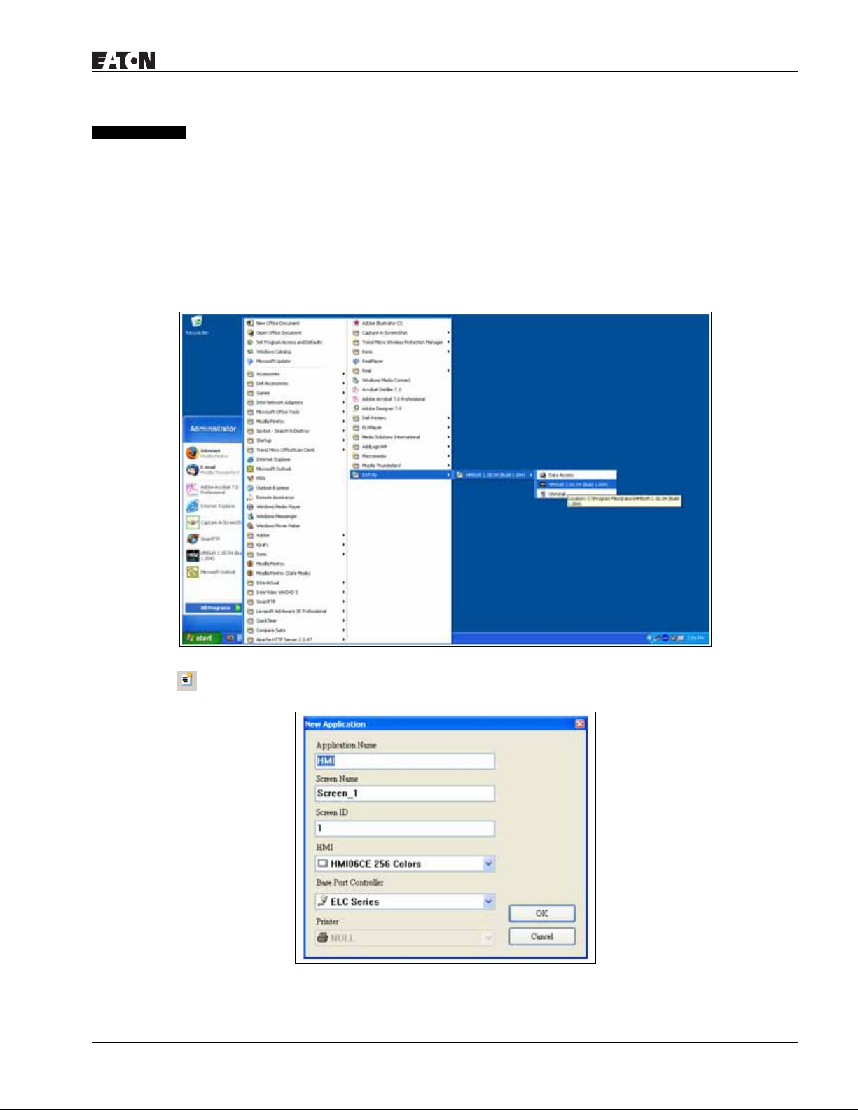
HMi Operator Interface
January 2007
Chapter 2 — Creating and Editing Screens
HMisoft Setup
This chapter introduces the general functions of the HMisoft screen editor. Detailed information for each
function is discussed in following chapters.
Getting Started
After setup, you can start HMi from Windows taskbar, click Start > Programs > Eaton > HMisoft (Figure 2-
1).
Figure 2-1: Starting HMi from the Windows Taskbar
After clicking or selecting File > New, to create a new application, the new application box is displayed in
Figure 2-2.
Figure 2-2: Creating a New Application
MN04802014E
For more information visit: www.EatonElectrical.com
2-1
Page 22
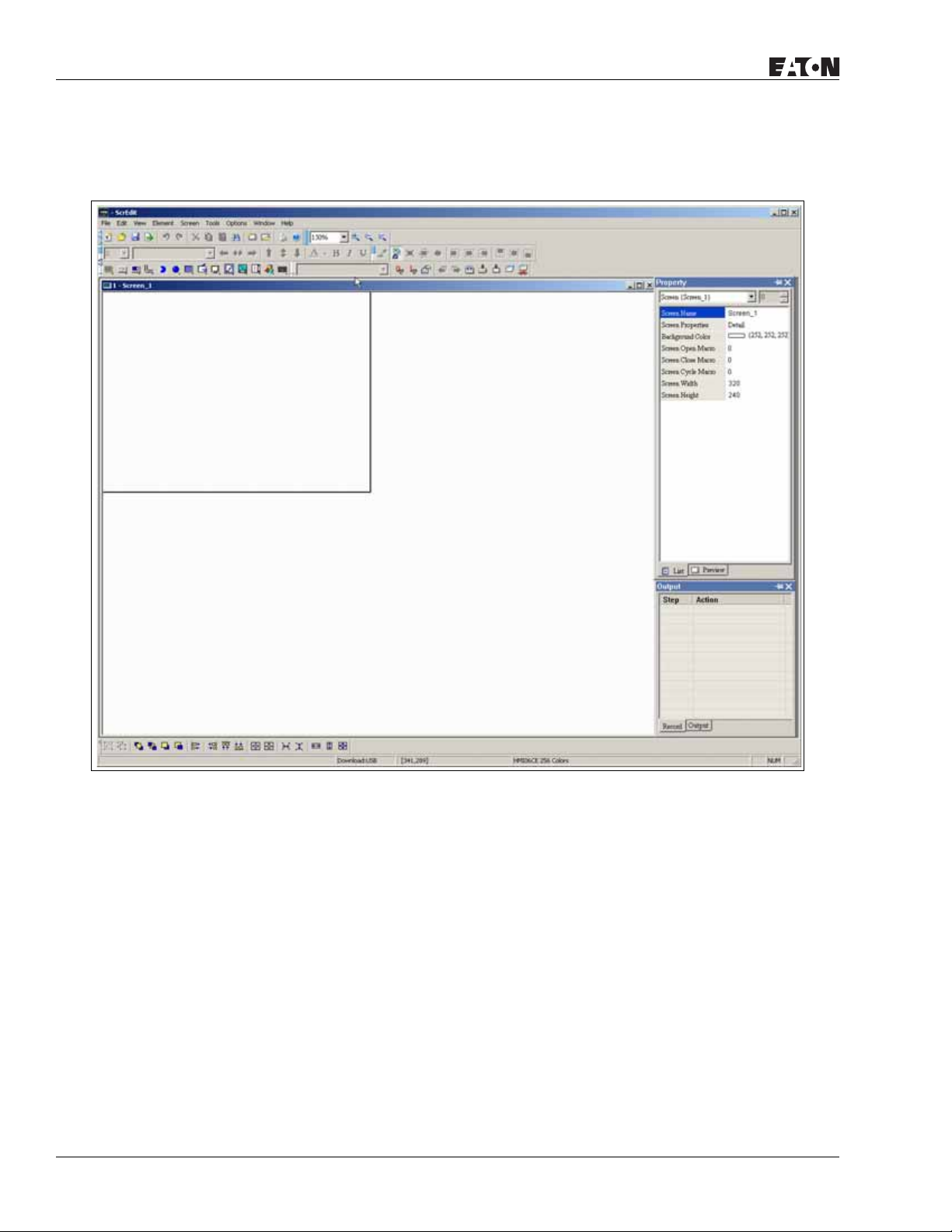
HMi Operator Interface
January 2007
Enter the Application Name, Screen Name, Screen ID and select connected HMi, controller or printer. Click
OK. A new application screen is opened in HMi (Figure 2-3).
2-2
Figure 2-3: New Application Screen of HMi
For more information visit: www.EatonElectrical.com
MN04802014E
Page 23
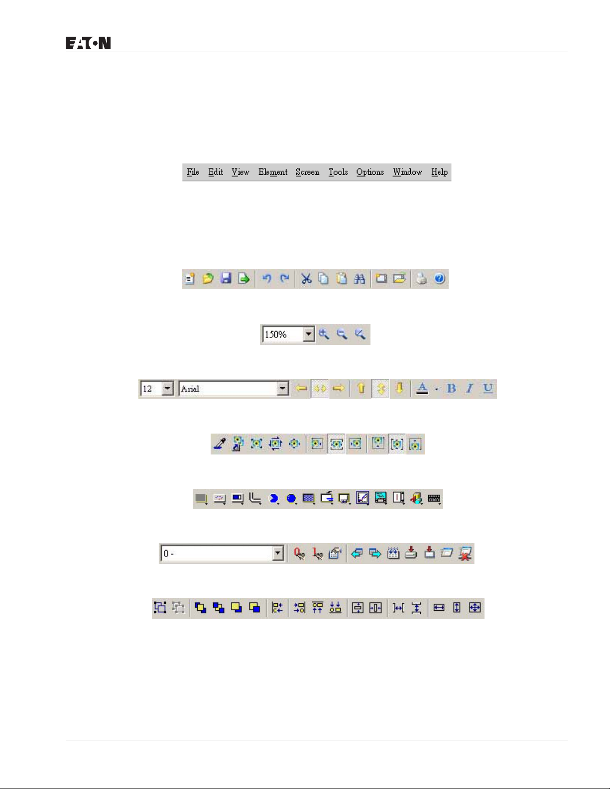
HMi Operator Interface
January 2007
There are five parts in the following HMi application window:
● Menu Bar
There are nine functions for selection: File, Edit, View, Element, Screen, Tools, Options, Window and
Help.
Figure 2-4: Menu Bar
●
Toolbar
The standard toolbar (Figure 2-5) is similar to the toolbar in Windows. For example, you can move the
Toolbar to the left side of the screen. Also, you can arrange the toolbar position by how you use it. The
following tool sets are on the toolbar in HMi.
Figure 2-5: Standard Toolbar
Figure 2-6: Zoom Toolbar
Figure 2-7: Text Format Toolbar
Figure 2-8: Bitmap Toolbar
Figure 2-9: Element Toolbar
Figure 2-10: Build Toolbar
Figure 2-11: Layout Toolbar
MN04802014E
For more information visit: www.EatonElectrical.com
2-3
Page 24
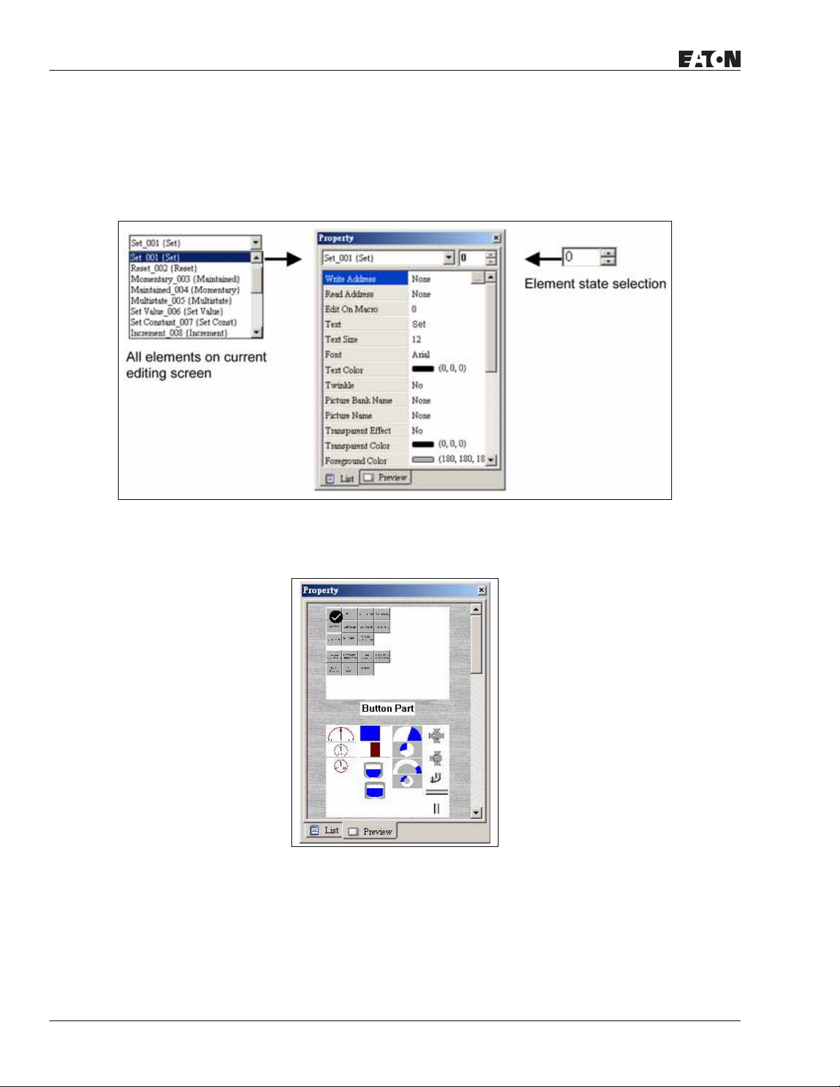
HMi Operator Interface
January 2007
● Property Table
The property table displays the property settings for each element placed on the screen. Right click on
the screen to display all elements or click on Element on the menu bar to choose and place an element
onto the screen. With the element highlighted, its properties will be displayed in the Property Table
(Figure 2-12), ready for editing. Chapter 3 details how to use each of the elements in your design.
Figure 2-12: Property Table
Figure 2-13 shows the preview tab of the Property Table. This tab shoes each screen, allowing you to
switch between them by double clicking on one.
Figure 2-13: Editing Screen Preview
2-4
For more information visit: www.EatonElectrical.com
MN04802014E
Page 25
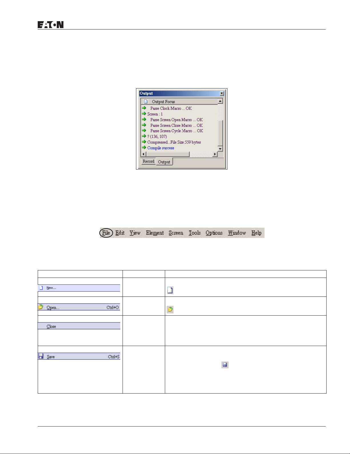
HMi Operator Interface
January 2007
● Output Window
The Output Window displays all the editing actions and output messages as your design is compiled. As
HMi is compiling, program errors are automatically detected and an error message is displayed in the
Output Window. To get to the error element window, click on the error message.
Figure 2-14: Output Window
Menu Bar and Toolbar (File)
HMi provides a convenient pull-down menu for the users to create, edit and manage elements, pictures,
graphs, macro programs, recipes and displays. The pull-down menu options of the Menu bar are described
as follows:
Figure 2-15: File Menu Toolbar
Table 2-1: File Menu
Icon Subject Description
New Open the current application by selecting File > New, or clicking
, or pressing Ctrl + N.
Open Open the current application by selecting File > Open, or clicking
, or pressing Ctrl + O.
Close Close the application by selecting File > Close.
If the application file exists, the Saving dialog box opens to
prompt you to save the file. If the application is new, you are
prompted to save the file with the file extension .dop.
Save Save the current application with the file extension .dop by
selecting
MN04802014E
File > Save, or clicking , or pressing Ctrl + S.
If the application is new, you are prompted to save the file with
the file extension .dop. If the application already exists, HMi will
automatically save the application without displaying a dialog
box.
For more information visit: www.EatonElectrical.com
2-5
Page 26

HMi Operator Interface
Table 2-1: File Menu (continued)
Icon Subject Description
Save As Save the current application to another file name by selecting File
Make SMC
Screen Data
Open SMC
Screen Data
Upload To upload screen data, select File > Upload. The password dialog
Upload Recipe To upload a recipe, select File > Upload Recipe. The password
> Save As. The Save As dialog box is displayed for you to enter
the new file name.
Before using this command, compile the data on the editing
screen. If you do not compile first, HMi cannot create the screen
data and an error message is displayed.
To create the screen data, select File > Make SMC Screen Data to
copy the compiled application to the SMC card. If the SMC card is
inserted in the HMi, HMi starts up by reading the data on the
SMC card.
You can view and edit the screen data that is stored on the SMC
card by using the SMC Screen Data function. To open the screen
data file, select File > Open SMC Screen Data, or pressing Ctrl + I.
A dialog box is displayed and you select the file you want to open.
box is displayed. You must enter a password to access the Save
as Dialog box. Enter the name of the application to start the
upload. When the progress goes to 100%, the upload is complete.
To monitor the progress of the upload, access the progress box.
To stop the upload, click the Stop button.
dialog box is displayed. You must enter a password to access the
HMi. Enter the name of the recipe to start the upload. When the
progress goes to 100%, the upload is complete.
January 2007
To monitor the progress of the upload, access the progress box.
To stop the upload, click the Stop button.
Update
Firmware
Password
Protect
Use this option to upgrade
HMi.
HMi firmware or to add a function to
To enable or disable the password protect option for an
application or recipe, select File > Password Protect. If the current
application or recipe is password protected, a symbol appears in
front of the Password Protect command on the pull-down. You
must enter a password before the .dop file can be opened.
To set a password, select Option > Workstation Setup.
Print To print the current screen, select File > Print,
or click the , or press Ctrl + P.
Print Preview To preview the screen print before sending the image to the
printer, select File > Print Preview.
Print Setup To choose the printer and paper options, select File > Print Setup.
Exit To close all open editing files, select File > Exit.
If the file is has been changed and not saved, the Saving dialog
box is displayed.
To cancel the exit from HMi, click the Cancel button.
2-6
For more information visit: www.EatonElectrical.com
MN04802014E
Page 27
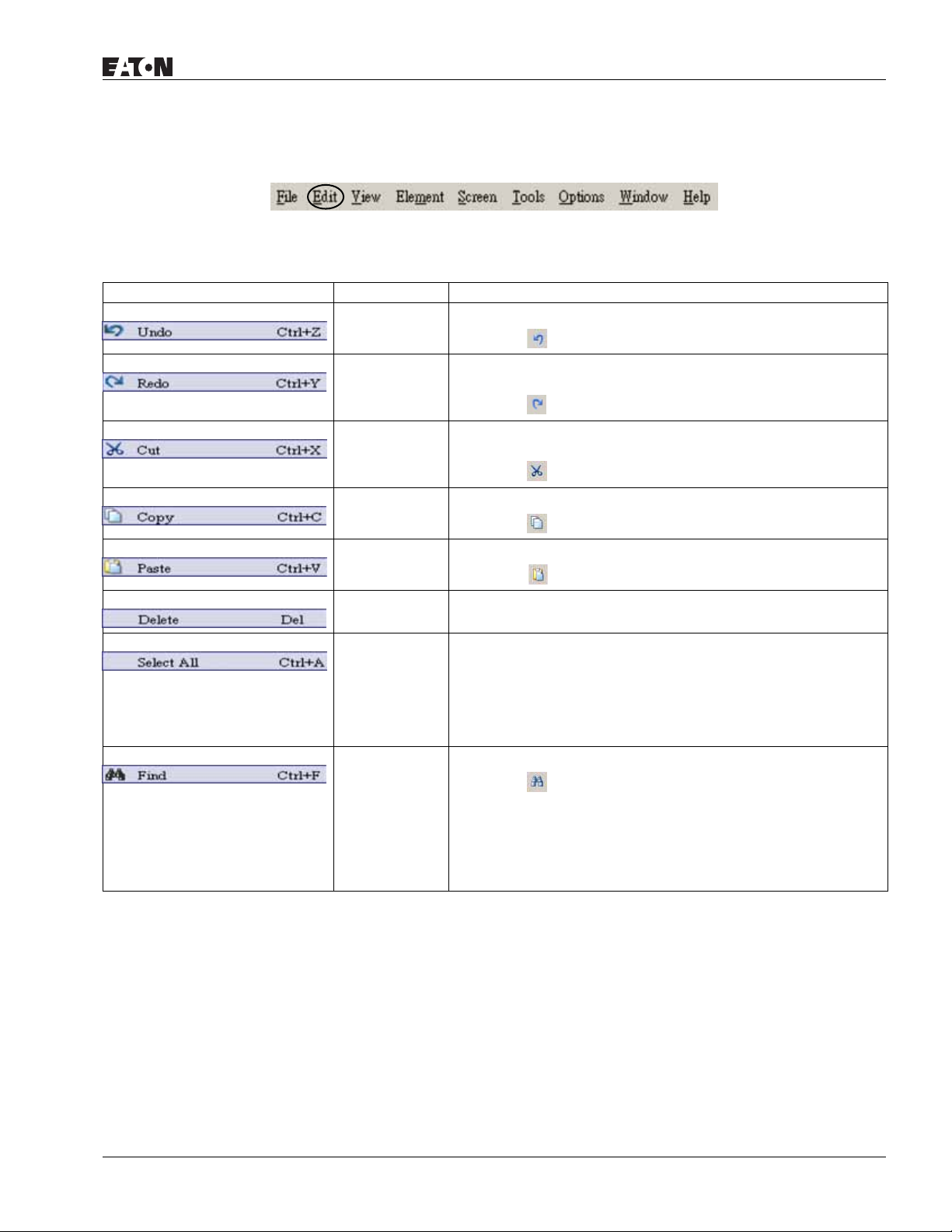
January 2007
Menu Bar and Toolbar (Edit)
Figure 2-16: Edit Menu Toolbar
Table 2-2: Edit Menu
Icon Subject Description
Undo To undo the last action, select Edit < Undo,
or click the , or press Ctrl + Z.
Redo If you have selected the Undo command by mistake and what to
recapture the last action, select Edit > Redo,
or click the , or press Ctrl + Y.
Cut To delete a selected element and save it to the clipboard, select
Edit > Cut,
HMi Operator Interface
or click the
, or press Ctrl + X.
Copy To copy a selected element to the clipboard, select Edit > Copy,
or click the , or press Ctrl + C.
Paste To paste an element from the clipboard, select Edit > Paste,
or click the
, or press Ctrl + V.
Delete To delete a selected element, select Edit > Delete, or press the Del
key.
Select All To select all elements to remove everything, select Edit > Select
All, or press Ctrl + A.
When you use Select All, the element in the upper left corner will
be filled with a blue and white border as a base element.
Additional elements will be filled with a white and black border.
The base element is used to align or resize.
Find Content To find content that matches the find criteria, select Edit > Find,
or click the , or press Ctrl + F.
You can find element text, read address, write address or memory
address on the current screen or all screens. Once the content is
located, the found content is displayed in the output window. To
go to actual location of the found content, click in the output
window and HMi moves to the location of the found content.
MN04802014E
For more information visit: www.EatonElectrical.com
2-7
Page 28
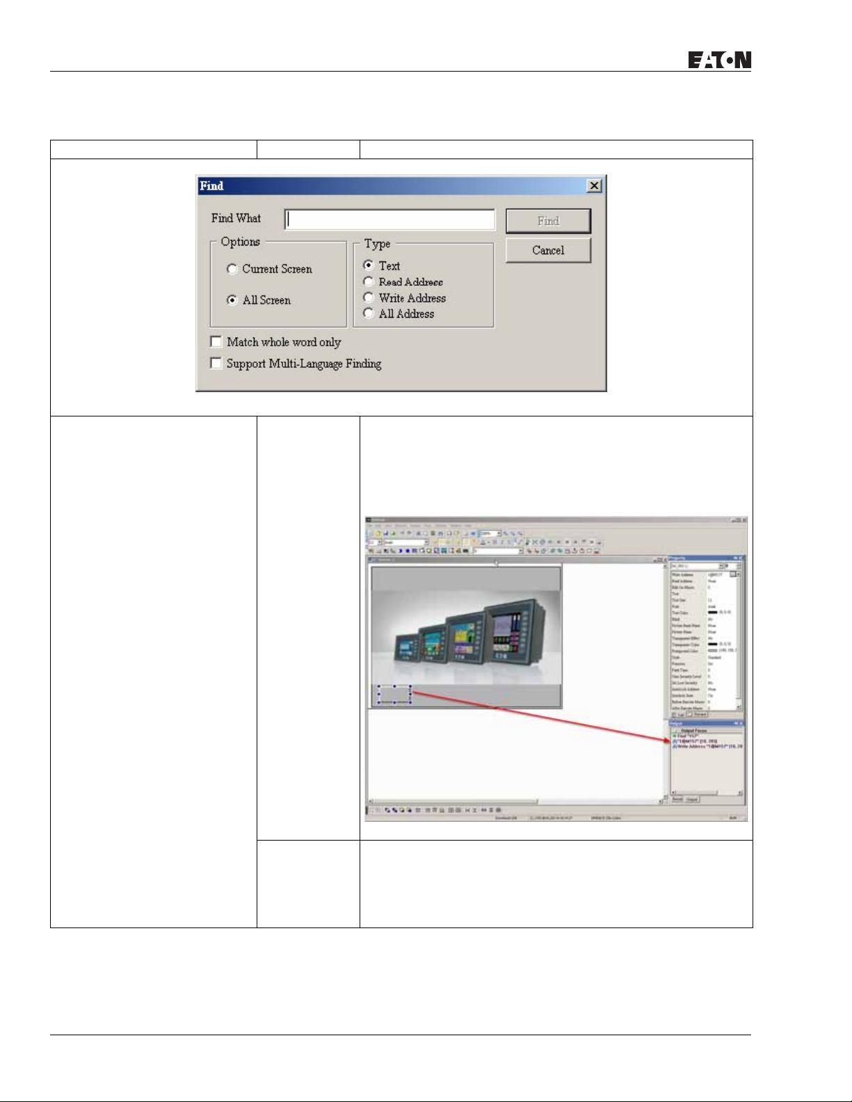
HMi Operator Interface
January 2007
Table 2-2: Edit Menu (continued)
Icon Subject Description
Find What Enter the word or phrase that you want to find.
Options Current Screen If you select the Current Screen button, HMi only searches the
current screen for the data entered into the Find What field.
The Output Window display all matching words or phrases. If you
double-click the word or phrase, HMi automatically takes you to
the file where the word or phrase resides. See Figure 2-17.
Figure 2-17: Find Options
All Screen If you select the All Screen button, HMi searches all the screens
for the data into the Find What field.
2-8
The Output Window display all matching words or phrases. If you
double-click the word or phrase, HMi automatically takes you to
the file where the word or phrase resides.
For more information visit: www.EatonElectrical.com
MN04802014E
Page 29
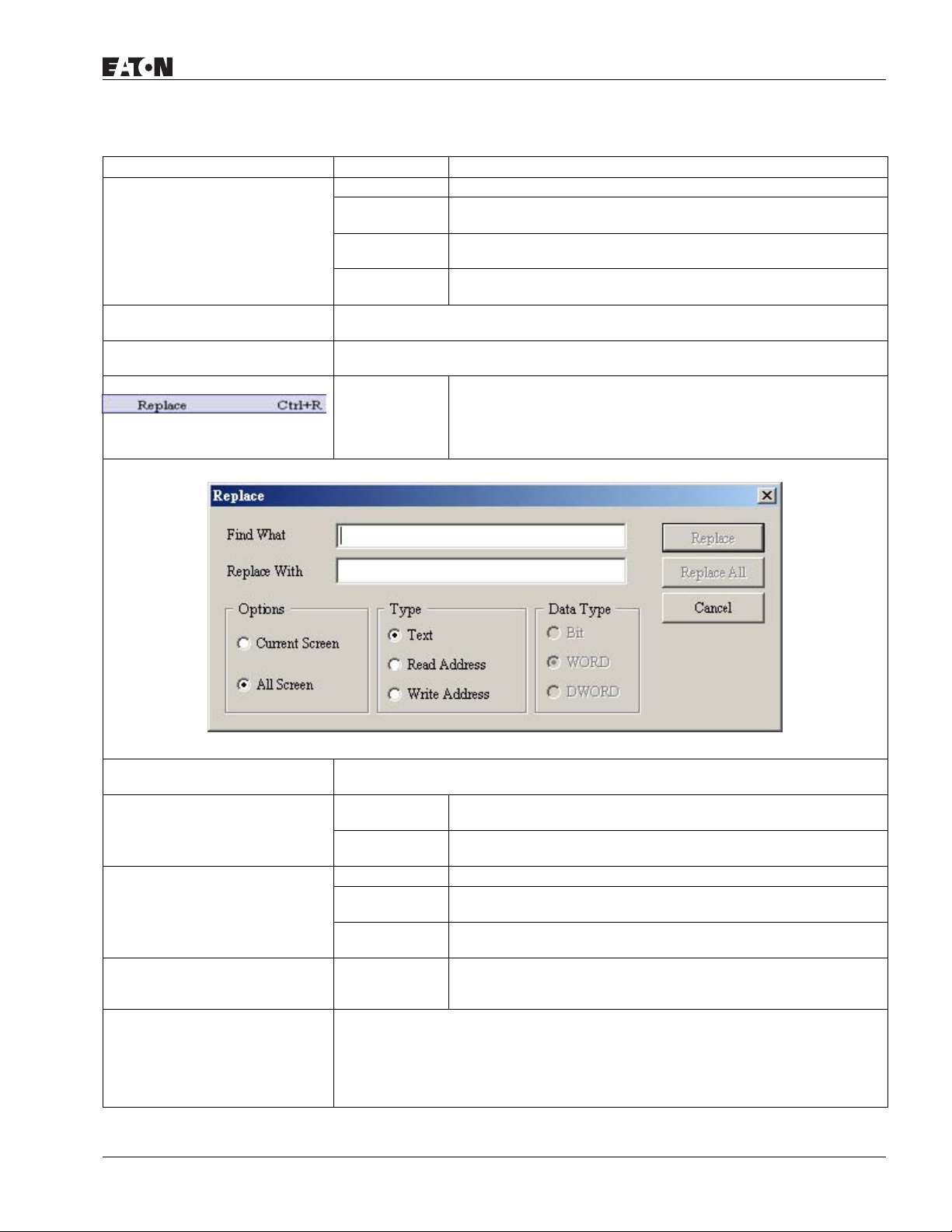
HMi Operator Interface
January 2007
Table 2-2: Edit Menu (continued)
Icon Subject Description
Type Text To specify the data type as Text, click the Text button.
Read Address To specify the data type as Read Address, click the Read Address
button.
Write Address To specify the data type as Write Address, click the Write Address
button.
All Address To specify the search to look for all data types, click the All
Address button.
Match whole word only To specify that the search look for an exact match to the data entered into the Find
Support Multi-Language Finding To specify that the search look at all multi-language words to match the data
What field, click the Match Whole Word Only box.
entered into the Find What field, click the Support Multi-Language Finding box.
Replace To replace the content that matches the replace criteria, select Edit
> Replace or press Ctrl + R.
You can replace element text, read address, write address or
memory address on the current screen or all screens.
Find What Enter the word or phrase that you want to replace.
Replace With Enter the word or phrase that you want to substitute for the word or phrase entered
in the Find What field.
Options Current Screen If you select the Current Screen button, HMi only searches the
current screen for the data that is to be replaced.
All Screen If you select the All Screen button, HMi searches all the screens
for the data that is to be replaced.
Type Text To specify the data type as Text, click the Text button.
Read Address To specify the data type as Read Address, click the Read Address
button.
Write Address To specify the data type as Write Address, click the Write Address
button.
Data Type Word
DWord
If the Read Address button or Write Address button are selected,
you need to select if the replacing content is Bit, Word, or Double
Word.
Replace
Replace All
If you are only replacing a single instance of the data and you have specified your
selections on the Replace Dialog box, click the Replace button.
If you want to replace all instances of the specified data automatically, click the
Replace All button.
MN04802014E
For more information visit: www.EatonElectrical.com
2-9
Page 30
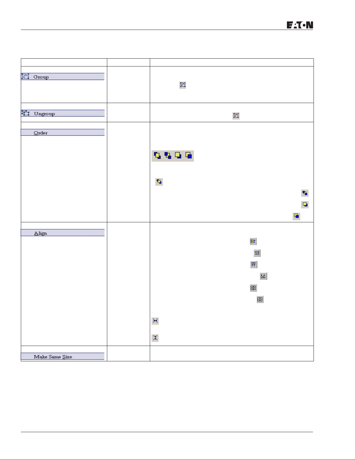
HMi Operator Interface
Table 2-2: Edit Menu (continued)
Icon Subject Description
Group To group two or more elements as a single unit, select Edit >
Group
or click the .
The new grouped unit can be moved, but the element size cannot
be changed.
Ungroup To ungroup an element that has been previously grouped,
January 2007
select Edit> Ungroup or click the
.
Order To arrange the stacking order of selected elements, select Edit >
Order, or select one of the specific order icons from the toolbar.
To bring a selected element to the top of the stack, click the
.
To send a selected element to the bottom of the stack, click the
.
To move the selected element forward one position, click the .
To move the selected element forward one position, click the .
To move the selected element back one position, click the .
Align To align an element, select Edit > Align, or click one of the Align
icons on the toolbar.
To move an element to the left, click the .
To move an element to the right, click the .
To move an element to the top, click the .
To move an element to the bottom, click the .
2-10
To center an element vertically, click the .
To center an element horizontally, click the .
To space selected elements evenly across the window, click the
.
To space selected elements evenly from top to bottom, click the
.
Make Same
Size
For more information visit: www.EatonElectrical.com
To have a second or additional elements be the same size as the
first element, select Edit > Make Same Size.
MN04802014E
Page 31

January 2007
Table 2-2: Edit Menu (continued)
Icon Subject Description
Text Process To set and change text direction and import text into HMi, select
Edit > Text Process or click the Text Process icons on the toolbar.
If the Text Process command is enabled, the is displayed next
to the Text Process command.
If you are importing text, you can elect to use the Text Bank Edit
Font. If you check the box next to the Text Bank Edit Font, the
imported text is displayed in the font of the Text Bank.
For the settings of the Text Bank, select Option > Text Bank.
Duplicate To copy one or more elements at the same time, select Edit >
Duplicate.
After you have selected this command, the Duplicate dialog box is
displayed.
HMi Operator Interface
MN04802014E
You enter the number of columns and rows to get the total copy
numbers. The minimum entry number must be more than 2 as
the original element is included in the total copy number.
If you want to copy only the rows, uncheck the box next to
columns. If you want to copy only the columns, uncheck the box
to rows.
To set the spacing between every element, set the pixel count in
the Spacing field.
To place the copied element by ascending or descending address,
click the Ascending Address or Descending Address button. The
unit of the address can be Word or Bit.
To place the element the copied element by the horizontal (Xdirection) or vertical (Y-direction) direction, click the X-Direction or
Y-Direction button.
For more information visit: www.EatonElectrical.com
2-11
Page 32

HMi Operator Interface
Menu Bar and Toolbar (View)
Table 2-3: View Menu
Icon Function Description
Standard Toolbar
New Create a new application
Open Open an old application
Save Save current edited application
Export Export an application to BMP format
January 2007
Figure 2-18: View Menu Toolbar
Undo Undo an action (some actions cannot be undone)
Redo Redo an action
Cut Cut selected elements
Copy Copy selected elements
Paste Paste the element that you copy or cut
Find Content Find specific text, write address or read address
New Screen Create a new screen
Open Screen Open an old screen
Print Print current application
Help Screen editor version
2-12
For more information visit: www.EatonElectrical.com
MN04802014E
Page 33

January 2007
Table 2-3: View Menu (continued)
Icon Function Description
Status Toolbar The Status Toolbar is enabled by default and can be found at the very bottom of the
screen. To disable, click View and then click on Status Toolbar to uncheck it.
Text Toolbar
Font Size Display and change text size
Font Select font
Aligns Left Align text to left
HMi Operator Interface
Center
The space at the right/left sides of text will be the same
Horizontal
Aligns Right Align text to right
Aligns Top Align text to top
Center Vertical The space at the top/bottom sides of text will be the same
Aligns Bottom Align text to bottom
Text Color Change text color
Bold Text bold
Italic Text Italic
Underline Add line under text
MN04802014E
For more information visit: www.EatonElectrical.com
2-13
Page 34

HMi Operator Interface
Table 2-3: View Menu (continued)
Icon Function Description
Bitmap Toolbar
January 2007
Select
Transparent
Use the suction tool to remove the color of the picture and determine the transparent
color of the picture.
Color
Change Mode
for Process All
If this function is enabled (this icon is pressed), not only the current picture with the
current state but also all pictures with all states are stretched, resized or aligned.
State Picture
Picture Stretch
Stretch the selected picture to the whole range of the element.
All
Picture Stretch
Scale the picture relative to original picture size.
Ration 1: 1
Picture Actual Resize the selected picture to the actual picture size.
Picture Align
Align the selected picture to left.
Left
Picture Align
The space on the right/left sides of the selected picture are the same.
Horizontal
Center
Picture Align
Align the selected element to right.
Right
Picture Align
Align the selected element to top.
To p
Picture Align
The space at the top and bottom of the selected element are the same.
Vertical Cen t e r
Picture Align
Align the selected element to bottom.
Bottom
Element Toolbar See Table 2-4 on page 19 for detailed description of all element toolbar items.
Layout (Build) Toolbar
Current Element State Text on selected element
View State
Switch and view current state OFF/1
OFF/1
View State
Switch and view current state ON/1
ON/1
Display All
Display all read/write addresses of all elements
Read/Write
Address
2-14
For more information visit: www.EatonElectrical.com
MN04802014E
Page 35

January 2007
Table 2-3: View Menu (continued)
Previous
windows
Next windows Select the next windows
Compile Compile current element
HMi Operator Interface
Select previous windows
Download
Screen Recipe
Download
Screen Data
On-line
Simulation
Off-line
Simulation
Layout Toolbar
Group Group the selected elements
Ungroup Ungroup the selected elements
Bring to Top Move the selected element to the front of all other elements
Send to
Bottom
Bring Forward Move the selected element forward one position
Send
Backward
Align Left Align the selected elements to left
Download screen data and recipe
Download screen data
Test editing file on PC side and connected to PLC
Test editing file on PC side and not connected to PLC
Move the selected element behind all other elements
Move the selected element behind one position
MN04802014E
Align Right Align the selected elements to right
Align Top Align the selected elements to top
Align Bottom Align the selected elements to bottom
Center
Set the element to be the vertical position of the work place
Vertically
Center
Set the element to be the horizontal position of the work place
Horizontally
Space Evenly
Make all the elements align in a consistent width
For Across
Space Evenly
Make all the elements align in a consistent height
For Down
Make Same
Make the selected elements to be the same width
Width
For more information visit: www.EatonElectrical.com
2-15
Page 36

HMi Operator Interface
Table 2-3: View Menu (continued)
Make Same
Height
Make Same
Size
Zoom Toolbar
Zoom level Sets zoom level, including 25%, 50%, 75%, 100%, 150%, 200% and 300%
Zoom in Increases the magnification level, including 150%, 200% and 300%.
Zoom out Decreases the magnification level, including 25%, 50% and 75%.
Actual Size Changes element size to actual size (100%).
Property Toolbar
Property Table Element property table. Refer to Chapter 3 for a detailed description.
Output Table When the compile function is enabled, all editing actions and output messages are
January 2007
Make the selected elements to be the same height
Make the selected elements to be the same size
displayed. Use this information to trace errors.
2-16
Output Window
Output Window During Editing
Output Result
For more information visit: www.EatonElectrical.com
Error Output
MN04802014E
Page 37

January 2007
Table 2-3: View Menu (continued)
Icon Function Description
Zoom In Zoom in to get a close look at the elements on HMi work place.
Zoom Out Zoom out to see more of the elements on HMi work place.
HMi Operator Interface
Actual Size
Return to actual size (100%). This size is relative to the screen size of HMi.
No matter zoom in or zoom out command, the zoom level could be 20%, 50%, 75%,
100%, 150%, 200%
or 300%. You can also zoom in or out by clicking or or selecting the Zoom
level.
Full Screen Full screen provides maximum view to edit in HMi. Full screen view hides all toolbars
and docking windows other than the HMi work place itself.
I/O Screen I/O screen provides maximum view to edit in HMi similar to Full screen. The difference
is that the I/O Screen shows the read and write addresses of the element and also
shows the referenced macro command.
Grid Setup Grid Setup is a function that can help you to align and position the element easily and
precisely. You can set the distance (spacing) between the grid dots.
Show Grid: Show the grid dots on the screen.
Snap to Grid: Make the elements snap to the grid so that the elements can cross
between the grid lines when you move them.
MN04802014E
Cross
Reference
Ta bl e
When creating and editing various kinds of elements, often the same address is reused. To avoid this situation, HMi provides the cross reference table function for your
convenience and quick reference. You can view the read/write addresses of the
selected element and see its relationship or connection with the addresses of other
elements, macro commands or the system control area. The first row of the cross
reference table displays the referred element that you selected. The following rows
display the elements which have the same write address. You can double-click a
specific row and HMi switches to the corresponding screen of the referred address.
For more information visit: www.EatonElectrical.com
2-17
Page 38

HMi Operator Interface
Table 2-3: View Menu (continued)
Icon Function Description
Element Part
List
When the Element Part List function is enabled, HMi sorts out and classifies all the
elements on the current screen. You can click the tab to switch to the classification that
you want to view. The related addresses and corresponding properties are listed in
each classification (Name, Describe, Write / Read address, Trigger address, Trigger
type, Interlock and Level) in each tab. You can double-click the column to let HMi select
the element automatically and allow you to edit the detailed property of the selected
element in the property table.
January 2007
2-18
For more information visit: www.EatonElectrical.com
MN04802014E
Page 39

January 2007
Menu Bar and Toolbar (Element)
Table 2-4: Element Menu
Icon Subject Description
Element Menu Toolbar
Button
HMi Operator Interface
Figure 2-19: Element Menu Toolbar
Meter
Bar
Pipe
Pie
MN04802014E
For more information visit: www.EatonElectrical.com
2-19
Page 40

HMi Operator Interface
Table 2-4: Element Menu (continued)
Icon Subject Description
Indicator
Data Display
Graph Display
January 2007
Input
Curve
Sampling
Alarm
Graphic
2-20
For more information visit: www.EatonElectrical.com
MN04802014E
Page 41

January 2007
Table 2-4: Element Menu (continued)
Icon Subject Description
Keypad
HMi Operator Interface
MN04802014E
For more information visit: www.EatonElectrical.com
2-21
Page 42

HMi Operator Interface
Menu Bar and Toolbar (Screen)
Table 2-5: Screen Menu
Icon Subject Description
Screen In Screen options, HMi provides some screen editing functions.
Create a new screen. Select Screen > New Screen or
New Screen
click , or press Shift + N to open a new editing screen. The new screen can be
named and numbered by you.
January 2007
Figure 2-20: Screen Menu Toolbar
Open Screen Open an old screen. Select Screen > Open Screen or click , or press Shift + O.
When choosing Open Screen, you can preview each screen in the Open Screen dialog
box.
Screen
Management
When Screen Management function is enabled, you can duplicate, paste and cut the
screen using the mouse, just like Microsoft Windows Explorer. In the Screen
Management dialog box, right-click to select the Edit Save Screen function. For the
setting of screen saver, click Options > Configuration > Other.
Cut Screen Select Screen > Cut Screen or press Shift + T to cut the whole screen to the clipboard.
Note: You cannot undo the action of Cut Screen. It is the same as Delete Screen. The
cut screen is lost but it can be pasted from the clipboard to recover.
Copy Screen Select Screen > Copy Screen or press Shift + C to copy the whole screen.
Paste Screen To paste the whole screen, select Screen > Paste Screen or press Shift + P. The screen
settings are the same as the original screen, except for the new screen name.
2-22
Delete Screen Select Screen > Delete Screen or press Shift + D to delete the current screen or
element.
Note: After executing Delete Screen, you cannot undo the action.
Export To export an application to BMP format, select Screen > Export or click , or press
Shift + E.
For more information visit: www.EatonElectrical.com
MN04802014E
Page 43

January 2007
Table 2-5: Screen Menu (continued)
Icon Subject Description
Import You can import a picture to be the ground of the editing screen. Notice that the ground
of the editing screen is different than the base screen. The nature of imported picture
differs greatly from that of base screen. The imported picture cannot exist in HMi as an
element. However, the base screen can be regarded as an element and then exist in
the editing screen after compile operation is completed. The file types of available
imported picture can be BMP, JPG and GIF, etc. To import, select Screen > Import or
press Shift + I.
HMi Operator Interface
Clear Import
Data
Screen Open
Macro
Screen Close
Macro
To free up disk space, clear the imported data that you no longer want to use. Select
Screen > Clear Import Data.
When the Screen Open Macro function is selected, the Macro is executed as the screen
is closed. (Refer to Chapter 4 for the usage and editing methods of the function.)
When the Screen Close Macro function is selected, the Macro is executed
automatically once the screen is closed. Refer to Chapter 4 for the usage and editing
methods of the function.
Screen Cycle
Macro
When Screen Cycle Macro function is selected, the Macro is executed periodically after
the screen is opened. (The macro is executed periodically by the cycle time setting).
Refer to Chapter 4 for the usage and editing methods of the function.
Screen
Properties
You can view and choose the properties of the current editing screen by selecting
Screen > Screen Properties or choosing Screen Properties from docking windows.
Screen Number The screen number range is 1–65535. Each screen number must be unique.
Screen
Application
Regarded as general view screen. The element created by the users can be
downloaded to HMi after compile operation and display on HMi LCD display. The
input type element, such as Button, Input and Keypad can be pressed on the HMi
display and used to execute print function.
MN04802014E
For more information visit: www.EatonElectrical.com
2-23
Page 44

HMi Operator Interface
Table 2-5: Screen Menu (continued)
Icon Subject Description
Sub-screen
Setting
Screen Width Set the width of sub-screen and the unit is Pixel.
Screen Height Set the height of sub-screen and the unit is Pixel.
Sub-screen
Position
The check box next to “This screen is a sub-screen” can be checked only when General
View Screen option is selected. Therefore, before setting sub-screen function, ensure
the General View Screen option is selected.
Select “Center on display” to show the sub-screen inn the center position of HMi
display.
January 2007
To position the sub-screen to another position on the HMi display, input the coordinate
value directly (X and Y axis) or click to drag the sub-screen to the desired position.
Title Bar When the check box next to “Use Title Bar” is checked, the title bar is displayed when
opening the sub-screen.
Macro Cycle
Delay
Fast Refresh
Rate
Sets Macro Cycle Delay time every time this screen is executed. The range of the
macro cycle delay time is between 100 ms to 5 s.
There are three levels of the Fast Refresh Rate: High, Medium and Low. Use this
function to make elements display immediately when switching screens. Only four
elements can be renewed in each screen.
2-24
For more information visit: www.EatonElectrical.com
MN04802014E
Page 45

HMi Operator Interface
January 2007
Menu Bar and Toolbar (Tools)
Figure 2-21: Tools Menu
Table 2-6: Tools Menu
Icon Subject Description
Compile To compile the editing screen, select Tools > Compile or click or press Ctrl + F7. If
this application is a new application, HMi reminds you to save before compiling. If this
application has been saved or it is an old application, it will compile without a prompt.
During compiling, all of the compiling messages, including any errors, will be written
to an output field. An object file is produced if there were are no errors during the
compile process.
Debug Compiling Error during Compiling Process
1. Create a new application.
2. Create two editing screens.
3. Create a button element on these two screens respectively and do not change the element default property as shown
in Figure 2-22.
MN04802014E
Figure 2-22: Creating a Button Element
For more information visit: www.EatonElectrical.com
2-25
Page 46

HMi Operator Interface
January 2007
Table 2-6: Tools Menu (continued)
Icon Subject Description
Debug Compiling Error During Compiling Process (continued)
4. When pressing icon to execute compile operation, the error message dialog box pops up to warn you of any
compile error. In Figure 2-23, two errors occurred and they are all displayed in the output window.
Figure 2-23: Compiling Errors During Compiling Process
5. Once an error occurs, the corresponding message displays in output window. You can click the error message and
HMi switches to the error element window automatically.
Download
To download screen data and the recipe to HMi, select Tools > Download Screen &
Screen &
Recipe
Recipe or click or press Ctrl + F8. If PC cannot connect to HMi, the error messages
are displayed. To set the download interface, select Options > Configuration or select
Options > Environment. The download interface can be USB or RS-232.
Download
Screen
2-26
To download screen data to HMi, select To ol s > D o w n lo a d S cr e en or click or press
Ctrl + F9.
For more information visit: www.EatonElectrical.com
MN04802014E
Page 47

January 2007
Table 2-6: Tools Menu (continued)
Icon Subject Description
HMi Operator Interface
Download
Recipe
On Line
Simulation
Off-Line
Simulation
Get Firmware
Information
Downloads the recipe to HMi. Select Tools > Download Recipe to download only the
recipe data. The file extension name of a recipe file is .rcp.
To run the online simulation, select Tools > On Line Simulation or click or press
Ctrl + F4.
To run the online simulation, your PC should be connected to the PLC via the PC
communication port (COM1 or COM2).
To test the editing screen, the read/write addresses and the Macro to see if they are
correct, you can run an off-line simulation. To run the off line simulation, select Tools >
Off Line Simulation or click or press Ctrl + F5.
Connects to the HMi over the USB connection and provides the current firmware
version.
MN04802014E
For more information visit: www.EatonElectrical.com
2-27
Page 48

HMi Operator Interface
Menu Bar and Toolbar (Options)
Table 2-7: Options Menu
Icon Subject Description
Configuration To access the configuration options, select Options > Configuration. This dialog box is
divided into five tabs: Standard, Communication, Print, Default and Other. These tabs
are covered in detail in Table 2-8 on page 35.
Alarm Setup To set the alarm, select Options > Alarm Setup. The alarm setup should set with the
alarm function in element settings. HMi executes the alarm function automatically if
both settings are set. When the specified conditions are matched (if condition occurs in
specific address, ON enabled or OFF enabled), HMi displays an Alarm Setup warning
dialog box automatically. In this dialog box, Delete, Modify, Import, Export and Close
are options. For more information for the settings of Alarm Setup, refer to Chapter 3.
January 2007
Figure 2-24: Options Menu
History Setup History Setup should be used with sampling elements. Refer to Chapter 3 for more
detailed information.
Recipe Setup The Recipe function provides the controller a convenient parameter input method. You
can transmit the designated parameter to the controller by using HMi recipe after
finishing editing recipe. The recipe can be set and modified through the recipe dialog
box and can be saved and used independently without the application, allowing
recipes to be used for all brands of models. Before using a recipe, you should enable
the recipe function first by selecting Tools > Recipe. After the recipe function is
enabled, the Recipe Setup dialog box pops up and you can start to edit the recipe.
2-28
For more information visit: www.EatonElectrical.com
MN04802014E
Page 49

January 2007
Table 2-7: Options Menu (continued)
Icon Subject Description
Recipe Setup
HMi Operator Interface
Enable Recipe
When the check box next to “Enable Recipe” is checked, the recipe function is enabled.
If the users do not enable this function, the users cannot do this function even if the
users have downloaded recipe data.
MN04802014E
For more information visit: www.EatonElectrical.com
2-29
Page 50

HMi Operator Interface
Table 2-7: Options Menu (continued)
Icon Subject Description
Address
The users can input the starting address of recipe data here. It can accept the address
in PLC input
format and internal memory format. The users also can click to get the address
input dialog box shown in Figure 2-25 to input the starting address.
January 2007
Length
Figure 2-25: Input Starting Address Dialog Box
Use the length field to set the recipe length. The unit is word and it should be set to
more than 0. Otherwise, the following dialog box (Figure 2-26) displays.
Figure 2-26: Length Input Error Message
2-30
For more information visit: www.EatonElectrical.com
MN04802014E
Page 51

January 2007
Table 2-7: Options Menu (continued)
Icon Subject Description
Group
Use the group field to set the group number of recipe. The group number should be
set to more than 0. Otherwise, the following dialog box (Figure 2-27) displays on the
screen.
Input
After setting length and group number of recipe, the users can click the
button to edit the recipe data. The memory size for a recipe is limited. When the Hold
Data Place is selected as SRAM, the memory size for recipe is 64K. It indicates that the
total recipe size should be less than 64K. (Length x groups should be less than 64 X
1024) If one of them is 0 or exceeds the limit, you will see a warning message (Figure
2-28) displayed on the screen.
HMi Operator Interface
Figure 2-27: Group Input Error Message
Figure 2-28: Input Error Message
Some HMi, such as (HMI08CE) (HMI10CE) support USB host function. It
indicates that these models have a built-in USB host interface and the users
can input more recipe data via this interface. However, there is still a limit for
the input value of recipe length and groups. When Hold Data Place is selected
as USB disk, the length x groups should be less than 410241024 (4Mb). You
can change the selection of Hold Data Place by selecting Options >
Configuration > Standard. Refer to Table 2-8 on page 35.
MN04802014E
For more information visit: www.EatonElectrical.com
2-31
Page 52

HMi Operator Interface
Table 2-7: Options Menu (continued)
Icon Subject Description
Input
January 2007
Open
Save
Reset
To load recipe data, click . The loaded recipe data does not contain the starting
address of recipe data. Therefore, regardless of which PLC brand connecting to HMi,
they all can use the same recipe file. It also can open Windows Excel CSV files.
To save the editing recipe data as a file, click When saving the recipe file, the starting
address will not be saved. This lets you use the same recipe file in the different PLC
brand. You can save the recipe file as Windows Excel CSV file.
When you click , all related recipe settings and input recipe data are deleted.
2-32
For more information visit: www.EatonElectrical.com
MN04802014E
Page 53

January 2007
Table 2-7: Options Menu (continued)
Icon Subject Description
Clear All input recipe is cleared to 0 (zero) when clear function is selected. Refer to Figure 2-
29.
Print Prints all recipe data on the current screen.
OK
After inputting the recipe data, the users can click to save the recipe data for
transmitting or modifying. At the same time, HMi checks the validity of all input recipe
data. If there is invalid input recipe data value, the OK function is not executed
successfully. For example, in Figure 2-30, HMi found an error and a warning message
dialog box displays on the screen as no input address was entered.
HMi Operator Interface
Figure 2-29: Clear Recipe Setup
MN04802014E
Cancel
Figure 2-30: Error and Warning Message Dialog Box
To exit the Recipe Setup dialog box without saving, click .
For more information visit: www.EatonElectrical.com
2-33
Page 54

HMi Operator Interface
Table 2-7: Options Menu (continued)
Icon Subject Description
Tag Table Use the tag table to replace the specific address with the user-defined words or
characters. For example, if the users want to replace the PLC address 1@Y0 with the
word “OS”, define it in Tag Table option.
January 2007
Screen
Print Setup
Screen Saver
Provides more efficient print layout management function. Refer to the example below
on next page.
Drag and drop screens to screen saver setup.
Setup
Picture Bank Use this option to import various pictures to enrich the screens selection. Select
Options > Picture Bank to execute this function.
Text Bank Input common or frequently used text and terms into the Text Bank. You can select the
text from the Text Bank to enter it on the element.
Submacro Use this option to edit a sub-macro that is to be called by another Macro. For the
Macro function, refer to Chapter 4 for more details.
Initial Macro Use this option to edit initial macro. The initial macro is executed automatically after
the power is applied to HMi (power on). For the Macro function, refer to Chapter 4 for
more details.
2-34
Background
Macro
Use this option to edit the background macro. For the Macro function, refer to Chapter
4 for more details.
Clock Macro Use this option to edit clock macro. After HMi is turned on and starting the initial
setup, the clock macro is be executed automatically by clock setting time. For the
Macro function, refer to Chapter 4 for more details.
Environment Use this option to complete the environment settings of Screen Editor.
For more information visit: www.EatonElectrical.com
MN04802014E
Page 55

January 2007
Table 2-8: Configuration Options
Standard Tab in Configuration Option
HMi Operator Interface
Application Name (Standard) Enter the name of the file for the
application.
HMi (Standard) Selects the HMi series type for different functions and requirements.
Base Port Controller
(Standard)
Retained Data Location
(Standard)
Sets the connecting external controller: the software provides various controllers
sorted by manufacturers for you to select.
The backup memory data can be saved in SRAM, SMC and USB Disk only. You can
select one of them from the Hold Data Place drop-down list. However, USB Disk
selection is only available in some HMi models. If HMI06BE, HMI06GE and HMI06CE
are chosen, the backup memory data only can be saved in SRAM and SMC.
MN04802014E
For more information visit: www.EatonElectrical.com
2-35
Page 56

HMi Operator Interface
January 2007
Table 2-8: Configuration Options (continued)
Standard Tab in Configuration Option (continued)
Password (Security) Use this option to set the highest priority password. There are 8 levels for the
Starting Level (Security) Use to set start-up priority. The highest level is 7 and the lowest level is 0.
Enable USB Updating Check (Customer supplied)
Insufficient Password Level
Prompt
Address (Control Block) Use to set the starting address of system control block.
Size (Control Block) The length of control block will be different depending on different function. (For
Auto Reset Flags If the Auto Reset Flag box is checked, the register in the control block is cleared to 0
Address (Status Block) Use to set the starting address of system status block. The length is constant 6 words.
Optimize Type Optimize - Dynamic When switching the screen, optimize all
Upload / Download You can select USB or PC communication port (i.e. RS-232) to upload and download.
Startup Delay Time Use to set delay time for waiting the startup of external controller (i.e. PLC). The range
Clock Macro Delay Time Use to set interval time when executing clock macro. The range is 100 – 65535 ms.
password. This password option is also the password protection for the file
(application).
(Customer supplied)
example, the length should be at least 8 Words when using multi-language function.)
For more detailed information of system control block, refer to Chapter 5.
Notice that the when the control block size is set to 0, the control block function is
disabled.
when any operation is finished in the control block.
Each word indicates the different status value of HMi system. Refer to Chapter 4 for
important parameters of system status area. For more detailed information of system
status block, refer to Chapter 5.
elements that read addresses on the
screen.
When this function is selected, all
elements that read addresses on the
screen will display incorrect values for a
short time. The display value will become
normal after optimization is completed.
Optimize - Static Optimize all elements that read addresses
on the screen during compile operation.
is between 0 – 255 seconds.
2-36
For more information visit: www.EatonElectrical.com
MN04802014E
Page 57

January 2007
Table 2-8: Configuration Options (continued)
Communication Tab in Configuration Option
HMi Operator Interface
MN04802014E
For more information visit: www.EatonElectrical.com
2-37
Page 58

HMi Operator Interface
Table 2-8: Configuration Options (continued)
Add / Delete Controller
Connection
Add Press Add button to determine the connecting device name and
Delete Use to delete the existed connecting controller (one application
Modify Modify the connecting controller or change the controller name.
January 2007
the controller:
Use to set the connecting PLC. Available connecting PLC will be
different depending on HMi type. HMi can support up to three
different controllers simultaneously.
needs to connect at least one controller).
2-38
For more information visit: www.EatonElectrical.com
MN04802014E
Page 59

HMi Operator Interface
January 2007
Table 2-8: Configuration Options (continued)
Communication Tab in Configuration Option (continued)
Controller Settings COM Port Use to set the COM port that communicates with HMi (COM1 or
Password Passwords are necessary for some connecting controllers before
Comm. Delay Time Use to set delay time for waiting the startup of external controller
Timeout Use to set communication time out time when communicating
Retry Count HMi will try to send a communication command to the external
Optimize Use this option to enable optimization function. If optimization
Size Limit This function is available only when “Optimize – Static” on the
When “Communication Interrupt times then cancel connected” is checked, HMi stops
communicating with the external controllers after the communication interrupt time is
reached. The purpose of this function is to avoid the communication error dialog box
will always show on the HMi screen when the communication error occurs after HMi
has retried. The range is between 1 – 255 times.
HMi Station It is used to set HMi station number. The range is within 0 – 255.
PLC Station It is used to set PLC station number. If PLC does not set station
Interface It is used to set communication interface. The default setting is
Data Bits There are two options 7 Bits and 8 Bits.
Stop Bits There are two options 1 Bits and 2 Bits.
Baud Rate Communication baud rate. There are 4800, 9600, 19200, 38400,
Parity There are three options: None, Odd and Even.
COM2). COM3 port only supported in some types of HMi.
communication.
(i.e. PLC). The range is between 0 – 255 ms.
with the external controller. The range is between 100 – 65535
ms.
controller repeatedly if the external controller does not respond
during communication. This option is used to set the number of
retry count times. A communication error dialog box will not
appear unless the number of retry count times is reached. The
range is between 0 – 255 times.
function is enabled, all read addresses of all related elements
will be optimized.
Standard tab is selected. It is used to avoid screen updating. The
speed may slow down when reading too long continuous
address.
number, it will use this default setting. The range is between 0 –
255.
RS232. There are three options RS232, RS422 and RS485.
57600 and 115200 these options. The users can enter the setting
value directly also but the maximum. setting value can not
exceed 187500.
MN04802014E
For more information visit: www.EatonElectrical.com
2-39
Page 60

HMi Operator Interface
Table 2-8: Configuration Options (continued)
Print Tab in Configuration Option
January 2007
2-40
For more information visit: www.EatonElectrical.com
MN04802014E
Page 61

HMi Operator Interface
January 2007
Table 2-8: Configuration Options (continued)
Apply Print Screen 1. Regarded as the print screen. The printer can print the created element after the
compile operation. This option is only available in HMi and only can be enabled after
the printer is set. For the setting of the printer, select Option > Configuration > Print
(Figure 2-31).
2. When the Apply Print Screen function is selected, the editing range is scaled to the
actual paper size. You can only print the elements within the range of the paper size.
When you select this option, all history data or sampling records of the editing
elements can be printed out. This option is usually used for print typesetting.
You can find printer setting by selecting Option > Configuration > Print. See
Figure 2-31.
Figure 2-31: Print Tab in Configuration Option
Standard Printer Use this option to set the connecting printer. The users can use
the drop-down list to specify the printer. The printers in the list
are sorted by manufacturer and the users can find the printer
easily.
Paper The users can use the Paper drop-down list to select the paper
size. The only predefined paper sizes in the list are A4 and Letter.
Quality Only 72 DPI option is provided.
Margin The users can determine the blank space (margins). Users can specify the top, bottom,
left and right margins and the unit is mm.
Interface Interface is used to set the printer interface. The users can specify the communication
port of the printer. There are Parallel Port and two USB options.
Auto Next Page When the “Auto Next Page” option is selected, the printer will print the next page
automatically. If the checkbox next to “Auto Next Page” is not checked, the printer will
print continuously without breaking for different pages.
Direction Direction is used to set printing orientation. There are two options: Vertical (Portrait)
and Horizontal (Landscape).
MN04802014E
For more information visit: www.EatonElectrical.com
2-41
Page 62

HMi Operator Interface
Table 2-8: Configuration Options (continued)
Default Tab in Configuration Option
January 2007
System Default Value Start up Screen Use this option to set the first display screen when HMi is
powered on and started up.
Default Format Sets the default value format when creating elements.
Default Screen
Background
System Error
Display Time
When a new editing screen is created, the users can use this
option to set the default screen background color.
Use this option to set the display time of system error message
dialog box. The range is 0 – 5 seconds.
Note that if the setting value is set to 0, the system error
message dialog box will not display on HMi screen.
System Key Use
Mode
It is used to set the system key action when the users press the
key. There are three options: Disable, Check Password and
Unchecked Password.
Element Default Value Element Font Size It is used to specify the default element font size when creating
an element.
Element Font Name It is used to specify the default element font name when creating
an element.
Element Font Color It is used to specify the default element font color when creating
an element.
Blink Time It is used to specify the default element blink rate when creating
an element.
Scroll Size (if
(Customer will enter text here)
element has Scroll
Size)
2-42
For more information visit: www.EatonElectrical.com
MN04802014E
Page 63

January 2007
Table 2-9: Other Tab in Configuration Option
Other Tab in Configuration Option
HMi Operator Interface
MN04802014E
For more information visit: www.EatonElectrical.com
2-43
Page 64

HMi Operator Interface
January 2007
Table 2-9: Other Tab in Configuration Option (continued)
Other Tab in Configuration Option (continued)
Save Screen Enable Save Screen This option should be selected when the users want to use Edit Save
Read Controller Address 1. The users can use this option to enable the screen saver. When
Screen function in Screen Management option. If this option is not
selected, even though the users have chosen the Edit Save Screen
function, the screen saver will not be started.
the setting value is 0, it indicates that the screen saver function is
disabled. If the setting value is a non-zero value, it indicates that the
screen saver function is enabled. When the users touch the HMi
screen, the screen saver function is ineffective.
2. If this option is not selected, the screen saver will be enabled
automatically when the Screen Saver Time set in HMi is reached. If
the screen saver function is enabled, the users can touch the HMi
screen to disable it.
Interval Time At Two Save
Screen
Ending of Save Screen
Mode
Use this option to set the interval time between two screen savers.
The range is between 1 – 255 seconds.
1. Return Original: Return to the original screen at that time when
the screen saver is enabled.
2. Indicate Screen: Specify the screen that will show after the screen
saver program ends.
2-44
For more information visit: www.EatonElectrical.com
MN04802014E
Page 65

January 2007
Table 2-9: Other Tab in Configuration Option (continued)
Other Tab in Configuration Option (continued)
Multi-Language New Press the New button to add a language option.
As shown as the figure above, the users have to enter the language
name and setting value. The setting value will be referred by the
system when setting multi-language. The range of the setting value
is within 0 – 255.
The users can press the button to change the flag color on the
language name tab.
Enable/Disable Delta HMi allows the users to edit multi-language screen, however
the users can use this option to determine which languages are
supported (enabled) or not supported (disabled) when downloading
data to HMi.
Remove Remove the existing language. HMi requires at least one language
for an application.
Modify Modify the existing language name and setting value.
Enable Edit Multi-
Language User Interface
Use this option to enable multi-language user interface. You can
view the multi-language display in the property table. The editing
interface is displayed in the figure below:
HMi Operator Interface
MN04802014E
For more information visit: www.EatonElectrical.com
2-45
Page 66

HMi Operator Interface
January 2007
How to Use Multi-Language Function
Example:
Create a Screen that has English, Traditional Chinese and Simplified Chinese. To switch the language
selection within the screen:
1. Create a new application.
Select HMi model “HMI06CE”.
Figure 2-32: Create New Application Screen
2. Create two button elements on the screen: “Set” and “Increment”
3. Control Block (Options > Configuration) Settings
Set the address as $200 and set the size as 8.
2-46
Figure 2-33: Configuration Settings Screen
For more information visit: www.EatonElectrical.com
MN04802014E
Page 67

HMi Operator Interface
燈
January 2007
4. Multi-Language Settings
Add English (Eng), Traditional Chinese (Trad) and Simplified Chinese (Simp). The setting values are 0, 1 and 2
for each language respectively.
Figure 2-34: Multi-Language Configuration
5. Set the display text of “Set” button element in different languages.
Figure 2-35: Set Alarm in Different Languages
●
Double click the English tab and enter “ ” in English.
● Double click the Traditional Chinese tab and enter “ ” in Traditional Chinese.
● Double click the Simplified Chinese and enter “ ” in Simplified Chinese.
Alarm
警示燈
警示
MN04802014E
For more information visit: www.EatonElectrical.com
2-47
Page 68

HMi Operator Interface
January 2007
6. In property setting of “Increment” button element, set the write address as the internal memory $207.
Figure 2-36: Input Macro Command
7. Set the setting value of “Before Execute Macro”. The users can enter the Macro command as
$207=$207%3.
2-48
For more information visit: www.EatonElectrical.com
MN04802014E
Page 69

January 2007
HMi Operator Interface
Figure 2-37: Set “Before Execute Macro“
8. Select the Compile command and execute Off Line Simulation. The text of the “Set” button is changed
to a different language by pressing the “Increment” button element.
MN04802014E
For more information visit: www.EatonElectrical.com
2-49
Page 70

HMi Operator Interface
Table 2-10: Alarm Setup
Alarm Setup Dialog Box
January 2007
Alarm Setting Address of
Alarm Block
Scan Time
(second)
Number of
Records in
History
Non-volatile Using this option saves data in SRAM when the power is turned off. The battery
Use this option to set the alarm starting address. It provides 512 alarms, 32
Words.
Sets how long it takes for the HMi to scan one time. The unit is seconds.
Use this option to retain a specific number of records. When the number of
records exceeds this setting value, HMi deletes the first record and insert the
new record into the last address. For example, if the setting value is set to 100
and the number of records in history exceeds 100, the first record is deleted
and the second record will become to the third record, the third record will
become to the forth record…and the 100th record will become to 99th record.
The new record (101st record) becomes the 100th record.
of the SRAM provides power when the power is turned off. (In some HMi
models, the users can save data in USB disk or SMC card when the power is
turned off and the capacity for saving alarm data depends on the capacity of
the USB disk or SMC card.)
2-50
For more information visit: www.EatonElectrical.com
MN04802014E
Page 71

January 2007
Table 2-10: Alarm Setup (continued)
Alarm Setup Dialog Box
HMi Operator Interface
Alarm Property
Setup
The users can double click a row of the alarm message contents table to edit
the alarm property.
There are 3 language tabs in Alarm Setup dialog box as multi-language
function is also supported here. Click the tab to edit the alarm message
contents according to your requirements.
The following Alarm Property Setup dialog box will display after double
clicking the row.
MN04802014E
Message Display message when an alarm occurs.
Color Display message color when an alarm occurs.
Tri gg er
Mode
Use this option to determine if the Bit is On or Off when an alarm
occurs.
Screen Display screen when an alarm occurs.
Delete Delete the alarm message contents.
Modify Modify the alarm message contents. You also can double click the mouse to
perform this function.
Import Import the Alarm Describe File into the alarm message contents table.
Export Export the alarm message contents from HMi and convert them to be Alarm
Describe.
For more information visit: www.EatonElectrical.com
2-51
Page 72

HMi Operator Interface
Table 2-10: Alarm Setup (continued)
Alarm Setup Dialog Box
January 2007
Alarm Moving
Sign
Enable It is used to enable the alarm moving sign.
Position It is used to determine the display position of alarm moving sign. It can be Top
or Bottom.
Direction Left Alarm message will move from right to left (Move to left).
Right Alarm message will move from left to right (Move to right).
Up Alarm message will move from bottom to top (Move to Up).
Down Alarm message will move from top to bottom (Move to Down).
Moving points Set the moving points every time for the alarm moving sign. The unit is Pixel
and the range is between 1 – 50 points.
Interval (ms) Set the interval time every time for the alarm moving sign. The unit is ms and
the range is between 50 – 3000 ms.
Background
Set the background color of the alarm moving sign.
Color
2-52
For more information visit: www.EatonElectrical.com
MN04802014E
Page 73

January 2007
Table 2-11: History
History Setup Dialog Box
HMi Operator Interface
Append Pressing Append button can add a history data. A
maximum of 12 history data can be added. After the
Append button is pressed, the following Buffer
Properties dialog box is displayed.
Read Address Set the starting address for sampling the history data.
Data Length
(Word)
Set the length of the Word the users want to sample. The range is between 1 – 13
continuous words. It indicates that a maximum of 13 continuous words can be
sampled.
Cycle (ms) Set the sampling cycle time for reading the address (how long it takes to read the
address one time). If the Trigger option is PLC, this option will be unavailable. The
range of the sampling cycle time
is 0 – 86400000 ms.
MN04802014E
For more information visit: www.EatonElectrical.com
2-53
Page 74

HMi Operator Interface
Table 2-11: History (continued)
History Setup Dialog Box
Sample Number This option is used with the Auto Stop option. If the Auto Stop option is selected,
January 2007
HMi stops recording the data after the numbers of records have reached the setting
value of Sample Number option. If the Auto Stop option is not selected, when
record number of data exceeds the setting value of Sample Number option, it will
delete the first record and insert the new record into the last address. For example,
if the setting value is set to 100 and the number of records in history exceeds 100,
the first record will be deleted and the second record will become the third record,
the third record will become the forth record…and the 100th record will become the
99th record. Therefore, the new record (101st record) will become the 100th record.
Stamp Time and
Date
Use this option to determine if the time and date are also recorded during sampling
operation.
Auto Stop Use this option to determine if HMi stops recording when the maximum number of
record data is reached.
Non-Volatile Using this option can enable to save sampling data in SRAM when the power is
turned off. The battery of SRAM provides power when the power is turned off. (In
some HMi models, the users can save data in USB Disk or SMC card when the
power is turned off and the capacity for saving history data depends on the capacity
of USB Disk or SMC card.)
Trigger There are two options: Timer and PLC.
OK / Cancel Press OK button to save the data and exit. Press Cancel to exit without saving data.
Delete Pressing Delete button will delete the history data.
Modify Pressing Modify button can modify the history data.
Table 2-12: Tag Table
Ta g Tab l e D i al og B o x
Open Opens a Tag File and import it into HMi.
2-54
For more information visit: www.EatonElectrical.com
MN04802014E
Page 75

HMi Operator Interface
January 2007
Table 2-12: Tag Table (continued)
Ta g Tab l e D i al og B o x
Save Save the settings or changes made in Tag Table dialog box as a Tag File.
Add Select the Tag type first: Internal Memory or Base Port (if the users has three or above communication
ports, the users will see Link2, Link3 …and vice versa). Press Add button to add and define Tag data.
Delete The users can use the mouse to select one row of the Tag table, and then press Delete button to delete it.
OK Press OK button to save the settings and exit.
Cancel Press Cancel to exit without saving.
MN04802014E
For more information visit: www.EatonElectrical.com
2-55
Page 76

HMi Operator Interface
January 2007
How to Use Print Function
1. Select Printer: Select File > New to get into the New Application tab and choose the printer using the
Printer drop-down list in New Application tab, or select Options > Configuration > Print to choose a
printer.
Figure 2-38: Select Printer
2. Configuring Print Setup: Select Options > Configuration > Print to open the Print tab. Use the Print tab
to configure the settings of printer, paper, quality and margin, etc.
2-56
Figure 2-39: Print Configuration Setup
For more information visit: www.EatonElectrical.com
MN04802014E
Page 77

HMi Operator Interface
January 2007
Create a Printed Report
1. Create a new screen by selecting Screen > New Screen) and set it as Apply Print Screen in Screen
Properties tab (Screen > Screen Properties).
Figure 2-40: Screen Properties Screen
MN04802014E
For more information visit: www.EatonElectrical.com
2-57
Page 78

HMi Operator Interface
January 2007
2. Create the element that you want to print. For example, if you want to print a Historical Trend Graph
and a X-Y Chart, you can create a Historical Trend Graph (Element > Sampling > Historical Trend Graph)
and a X-Y Chart (Element > Curve > X-Y Chart) first and then set their properties in the Property table.
The Property table provides the element property setting for each element. For information about each
element property settings, refer to Chapter 3.
Figure 2-41: Historical Trend Graph and X-Y Chart
3. Choose “Yes” or “No” using the “Print Successive Data” drop-down list to determine whether the Print
Successive Data function is selected or not. When “Yes” is selected, it indicates that Print Successive
Data function is enabled, and all the sampling records and data for the element will be printed.
2-58
Figure 2-42: Print Successive Data Function Enabled
For more information visit: www.EatonElectrical.com
MN04802014E
Page 79

HMi Operator Interface
January 2007
Print Screen Layout and Output
1. Select Options > Print Typesetting. Drag the mouse to decide which screen needs to be typeset and
printed. The screens on the left are all created screens and the screens on the right are the selected
screens. If a “General View Screen” is dragged to the right, it will become “Apply Print Screen” (Screen
Properties) automatically.
Figure 2-43: Screen Print Setup
2. Right click the mouse or use the function key to create a “Report List” button on a “General View
Screen”. Use this “Report List” button to enable the print function.
Figure 2-44: Report List Selection
MN04802014E
For more information visit: www.EatonElectrical.com
2-59
Page 80

HMi Operator Interface
January 2007
3. Set the properties of the “Report List” option. The Report Device can be SMC, USB disk or Printer. If you
select SMC or USB disk, the data will not print out, but the data will be sent to the SMC or USB.
Figure 2-45: Select Print Device
2-60
For more information visit: www.EatonElectrical.com
MN04802014E
Page 81

HMi Operator Interface
January 2007
How to Use Hard Copy Function
The Hard Copy function is available only when the screen is a “General View Screen”. If HMi detects the
“Print Typesetting” function is already set for the editing screen, the “Hard Copy” function will be
ineffective.
1. Set the Hard Copy Region in Screen Properties tab.
2. Enable the Print function.
Figure 2-46: Set the Hard Copy Region
MN04802014E
For more information visit: www.EatonElectrical.com
2-61
Page 82

HMi Operator Interface
Table 2-13: Picture Bank Browse
Picture Bank Browse Dialog Box
January 2007
Click the Picture Bank option to browse all
pictures saved in Picture Bank. When one
picture is selected, you can see the picture
in the preview window. Double leftclicking the mouse on the selected picture
will display the picture in an actual size
view.
New Picture Bank
Create a new picture bank. After clicking , the New Picture Bank dialog box is
displayed on the screen.
Open Picture Bank Open a picture bank file (*.pib file).
Uninstall Picture Bank Uninstall the selected picture bank. The uninstalled picture bank will be moved to
Recycle Bin.
Save Save the modified picture into the picture bank.
2-62
For more information visit: www.EatonElectrical.com
MN04802014E
Page 83

HMi Operator Interface
January 2007
Table 2-13: Picture Bank Browse (continued)
Picture Bank Browse Dialog Box
Import Picture Import pictures into the
designated picture
bank.
The formats of the
pictures in the picture
bank can be BMP, JPG,
GIF (static) and ICON
pictures. When
selecting this function,
the dialog box shown
will be displayed. The
users can then convert
the picture color in
advance to speed the
compile time or choose
“No changed” option to
retain the original color.
Export Export pictures in BMP format from the picture bank.
Delete Delete pictures in the picture bank.
Inverse Inverse the picture color - negative effect
Grayscale Convert the color picture to 256 color
grayscale.
Horizontal Mirror Horizontal mirror effect
Vertical Mi rror Vert i c al mirr o r effec t
MN04802014E
For more information visit: www.EatonElectrical.com
2-63
Page 84

HMi Operator Interface
Table 2-13: Picture Bank Browse (continued)
Picture Bank Browse Dialog Box
Shortcut Menu The users can right-click the mouse to display a shortcut menu shown on the
figure below. This shortcut menu shows a list of commands relevant to the
picture bank option. This allows the users to manage the pictures in the picture
bank more quickly and efficiently.
Table 2-14: Text Bank
January 2007
Text Bank Dialog Box
Append Press the Append button to add the text into the Text Bank. The multi-language editing is supported in
the Text Bank option. You can input the text or terms in different language and save them in the Text
Bank. The multi-language font can also be set at the same time.
Delete Press Delete button to remove the input text or terms in Text Bank.
Open Press the Open button to open and import the text or terms into Text Bank.
Save Press the Save button to save and export the text file.
Close Close and exit the text bank dialog box.
2-64
For more information visit: www.EatonElectrical.com
MN04802014E
Page 85

January 2007
Table 2-15: Environment Dialog
Environment Dialog Box
HMi Operator Interface
System Path Sets the location where HMi saves the system files, including some system reference data and
dynamic link library (*.dll) files. To avoid a system error and failure to find the file, we recommend
the users not change this setting if it is not necessary. (This option is disabled by default.)
Output Path Sets the location where HMi saves the output file after compile operation. Some functions, such
as on-line simulation, off-line simulation, file download and upload all refer to the files in this
location.
Options Toolbars/Windows Sets the option to display or not display toolbars or docking windows.
Language Choose English, Traditional Chinese or Simplified Chinese from the
Language drop-down list.
Upload/Download Determines the communication interface for upload and download. It
can be USB or PC COM Port.
Auto Saving… Time
Interval
Auto Open for Next
HMi automatically saves the file every specified number of minutes. The
unit is M (minute) and the setting range is between 0M – 120M.
HMi automatically opens the specified file every time you start HMi.
Execute Application
MN04802014E
For more information visit: www.EatonElectrical.com
2-65
Page 86

HMi Operator Interface
Table 2-15: Environment Dialog (continued)
Environment Dialog Box (continued)
Center Drawing Area When this option is selected, the editing screen will be placed in the
January 2007
center position.
Include Picture Data
For Uploading
If this option is selected, all pictures are also uploaded when the HMi
upload function is enabled. All uploaded pictures are saved in a file
named as “_L
OCALTEMP01.PIB”. The “Picture Bank Name” and the “Picture
Name” (set in Property docking window) of the editing elements will
refer to and link to this file. If HMi ends the editing abnormally, the file
name will be named as “_LocalTemp02.pib,” _LocalTemp03.pib …”, and
vice versa when uploading is executed the next time. The last two
numbers at the end of the file name will increase progressively.
Auto Convert Input
Address To Tag Name
For example, if you want to replace PLC address 1@Y0 with the word
“OS”, define it in Tag Table option in advance. When this option is
selected, HMi will automatically convert input address 1@Y0 to the
word “OS”.
Driver Reinstall HMi USB Drive: Press it to reinstall the HMi USB driver
Uninstall HMi USB Drive: Press it to uninstall the HMi USB driver
OK Press OK button to save the modified settings and exit the Environment dialog box.
Cancel Press Cancel button to exit the Environment dialog box without saving.
2-66
For more information visit: www.EatonElectrical.com
MN04802014E
Page 87

January 2007
Menu Bar and Toolbar (Window)
HMi Operator Interface
Table 2-16: Menu Bar and Toolbar (Window)
Icon Subject Description
Close Window Hide the current window, NOT exit the current window. Execute this function by
selecting Window > Close Window. To display the hidden window, select Screen >
Open Screen to open an old screen.
Close All
Windows
Hide all windows, NOT exit all windows. Execute this function by selecting Window >
Close All Windows. To display the hidden window, select Screen > Open Screen to
open old screens.
Next Window Switch the current window to the next window. If the current window is the last
window, the current window will not be changed even if this function is executed.
Previous
Window
Switch the current window to the previous window. If the current window is the first
window, the current window will not be changed even if this function is executed.
MN04802014E
Cascade Display all editing windows so they overlap. The title bar of each window is visible but
only the top window is fully visible. Execute this function by selecting Window >
Cascade.
For more information visit: www.EatonElectrical.com
2-67
Page 88

HMi Operator Interface
Table 2-16: Menu Bar and Toolbar (Window) (continued)
Icon Subject Description
Title Horizontal Display all editing windows from top to bottom. Execute this function by selecting
Window > Title Horizontal. The opened windows are displayed horizontally.
Title Vertical Display all editing windows from left to right. Execute this function by selecting
Window > Title Vertical. The opened windows are displayed vertically.
Help
About
HMisoft Display the version information of HMisoft.
January 2007
2-68
For more information visit: www.EatonElectrical.com
MN04802014E
Page 89

HMi Operator Interface
January 2007
Chapter 3 — Element Function
This chapter explains how to select an element and the special functions of each element in HMi.
How to Select an Element
Choose one of the following methods to select an element when editing the screens:
●
Right-click in the work place to display the shortcut menu (Figure 3-1), and then select the desired
element.
●
Select the Element command from menu bar (Figure 3-2).
●
Select the Element icon from the toolbar (Figure 3-3).
MN04802014E
Figure 3-1: Shortcut Menu Display
For more information visit: www.EatonElectrical.com
3-1
Page 90

HMi Operator Interface
January 2007
Figure 3-2: Selecting an Element Command from the Menu Bar
Figure 3-3: Selecting an Element Icon from the Toolbar
After selecting an element, drag it onto the work place to create a new element. To do this, click the starting
point on the screen. While holding down the mouse button, move the mouse diagonally to the ending point
of the element, then release the mouse button. The element will appear on the screen.
3-2
For more information visit: www.EatonElectrical.com
MN04802014E
Page 91

HMi Operator Interface
January 2007
Property Window Attributes
The following properties may be common to many of the objects in this chapter and are discussed here
instead of individually.
Button Elements
Table 3-1: Button Elements
Button
Type Macro Read Write Function
Set ON Yes Yes Press this button to set the address (Bit) to ON. The address setting remains
Reset OFF Yes Yes Press this button to set the address (Bit) to OFF. The setting address setting
Momentary ON
Maintained ON
Multistate No Yes Yes There are from 1 to 256 user-defined multistates available. A user can set the
Set Value No No Yes Press this button, to launch the “Numeric keypad” dialog box, and then you
Set Constant No No Yes Press this button to cause HMi to write the specific value into the address
Increment No Yes Yes Press this button to cause HMi to add up the values contained within the
Decrement No Yes Yes Press this button to cause HMi to subtract the constant value setting from the
Goto Screen No No No Press this button to switch to the screen that you designated.
Previous
Page
OFF
OFF
No No No Press this button to return to the previous screen.
Yes Yes Press this button to set the address (Bit) to ON and to execute the ON Macro at
Yes Yes Press this button to set the address (Bit) to ON. The address setting remains
ON even if you release the button or press it again. If there is an ON Macro, it
will be executed simultaneously.
remains OFF even if you release the button or press it again. If there is an OFF
Macro, it will be executed simultaneously.
the same time. The address setting remains ON when the button is released
and OFF when the button is pressed again. If you execute the OFF Macro
simultaneously, it remains OFF when the button is released.
OFF when the button is released. If there is an ON / OFF Macro, it executes
simultaneously.
execution sequence to the “next state” or the “previous state.” If a user sets
the next state, that state becomes state 2. If a user sets to the previous state,
then state 2 becomes state 1.
can enter the value setting directly. After you enter the value setting and press
ENTER key, HMi transmits the input value to the address setting.
setting.
address setting and the constant value setting, and stores/sends the results
back to the address setting.
value contained within the address setting, and stores/sends the results back
to the address setting.
MN04802014E
For more information visit: www.EatonElectrical.com
3-3
Page 92

HMi Operator Interface
January 2007
General Buttons
Press one of the general buttons to transmit an ON/OFF signal to the PLC. The four general buttons are: Set
button, Reset button, Momentary button and Maintained button. Refer to Tabl e 3 - 2 for the property
descriptions of the general buttons.
Table 3-2: Property Description of General Buttons
Property Description of General Buttons
Write
Address
Read
Address
Press the button next to the Write Address or Read Address to enter the Input dialog box, and then
select Write Address or Read Address.
Edit On/Off
Macro
The link type can be ether iBase Port or Internal Memory. If you connect to multi-connections, the new
connections are added into the Link drop-down menu by completing the following steps.
1. Select the Link option and Device Type
2. Enter the correct address.
3. Press the Enter key.
The corresponding numeric value will be recorded on the element that you selected.
Device types are described as follows:
$ Internal Register
(SDRAM)
$M Non-volatile Internal
Register (SRAM)
*$ Indirect Address
Register (SDRAM)
Edit On and Off Macro is available. For the Macro function, refer to Chapter 4 for more details.
RCP Receipt register
RCPNO Receipt Number Register
Other Other device names
supported by other
brands PLC. Refer to the
user manual of the PLC.
3-4
For more information visit: www.EatonElectrical.com
MN04802014E
Page 93

January 2007
Table 3-2: Property Description of General Buttons (continued)
Property Description of General Buttons (continued)
Te xt
Tex t Si ze
Font
Tex t Co lo r
User can select any of the available Windows® fonts. Press the button next to the Font tab to display
the Font Detail Setting dialog box.
In the Font Detail Setting dialog box, select the Font Name, Font Size and Ratio. The font can be any
Windows® font, the font size determines the height and the ratio determines the width. You may also
view the text format in the Preview window. If the multi-language function is used, the user can see the
different language tabs and can edit the different language font settings in the Font Detail Setting dialog
box.
HMi Operator Interface
Blink Select Yes to cause the element to blink while in this state.
Picture Bank
Name
Select the Picture Bank Name to see the picture banks available. After selecting a picture bank, double
click to select a picture.
Picture
Name
For information on creating a new or modifying an existing picture bank, see Table 2-13 on page 62.
Transparent
Effect
Transparent
Color
Use the eyedropper tool to determine the color that will appear transparent in the picture. The color
selected will be removed from the element and be changed to the foreground color. The effect on the
element before and after this action happens is shown in the figures below.
If the color selected has a greater color depth (65536 colors vs. 256) than the HMi screen allows, an error
will occur. You can select colors from the drop-down list to specify a transparent color, but there may be
chromatic aberration. An example of chromatic aberration is selecting a black color from the drop down
list, only to see that the black in the picture does not become transparent. In this case, the black in the
picture is a shade different than the black color selected.
The effect before this action is executed: The effect after this action is executed
Foreground
Standard Raised Round Invisible
Color
Style
You can specify the button style and foreground color as shown in the figures above by using this
option.
Function You can modify the element characteristic directly without recreating a new element. The element
characteristics that can be modified directly using this option are: Set button, Reset button, Momentary
button and Maintained button.
MN04802014E
For more information visit: www.EatonElectrical.com
3-5
Page 94

HMi Operator Interface
January 2007
Table 3-2: Property Description of General Buttons (continued)
Property Description of General Buttons (continued)
Push Time
(second)
Data Length Bit Multistate button can have two states.
Line Color Used to set the display color of the dynamic line element.
Line Size The unit is in Pixels and the range is between 1and 8.
Use this option to set the active time of the button. When this option is set, the button will be active after
pressing the button longer than the setting time indicated. The range set is between 0 – 10 seconds.
Word Multistate button can have 256 states.
LSB Multistate button can have 16 states.
Multistate Buttons
Table 3-3: Property Description of Multistate Buttons
Property Description of Multistate Buttons
The number state will vary by unit. In Word, the number state may be from 1 to 256; in LSB, the number state is 16;
with a Bit, the number state is 2. The unit of the read/write address will vary by the value unit. If the value unit is Word
or LSB, the unit of the read/write address will be the Word equivalent. If the value data type is Bit, the unit of read/write
address will be Bit. After obtaining the data from the read address, it will increase or decrease gradually according to
the next state or previous state and will write the new value to the write address. The change state of this button
depends on the read address. If you need to add or delete the total numbers state, edit the values in only element
property table.
Add/Remove
State
Sequence Switches the multistate sequence (previous state/next state).
Sets the number state of multistate buttons. One to 256 states can be set if the unit is Word, 16 states
can be set if the unit is LSB, and 2 states can be set if the unit is Bit.
3-6
For more information visit: www.EatonElectrical.com
MN04802014E
Page 95

HMi Operator Interface
January 2007
Set Value Button
Table 3-4: Property Description of Set Value Buttons
Property Description of Set Value Buttons
Press this button to launch a system built-in numeric keypad (TEN-KEY) that you can use to input the setting value
directly. Press the ENTER key to send the input setting value to the corresponding PLC register. The maximum and
minimum input setting values are all user-defined. You can also specify the mode to trigger the designated PLC
address before or after writing the setting value.
Tri gg er
Trig g e r M od e
Detail Range
Setup
Turns ON the designated PLC address before or after writing the setting value. Note: this function can be
used only to trigger PLC address to turn ON. If the PLC address needs to be triggered again, you must
reset the address to OFF.
Data Length There are 16-bit Word and 32-bit Double Word options.
Data Format Provides different kinds of data format for different data lengths:
Word Double Word
1. BCD
2. Signed BCD
3. Signed Decimal
4. Unsigned Decimal
5. Hex
6. Binary
1. BC D
2. Signed BCD
3. Signed Decimal
4. Unsigned Decimal
5. Hex
6. Binary
7. F l o a t i n g
Minimum Sets the minimum and maximum input setting values to determine the range of input
Maximum
setting value.
Integral Digits Determine the digit number of integer and decimal fraction. The digit number is not a
Fractional
real digit number value. It is only the display format. The digit number will be a real
decimal number only when the data format is selected as Floating.
Press OK when you have input the minimum and maximum value, and then HMi will examine the value
by referring to the selected data length, data format, and integral and fractional digits.
MN04802014E
For more information visit: www.EatonElectrical.com
3-7
Page 96

HMi Operator Interface
January 2007
Set Constant Button
Table 3-5: Property Description of Set Constant Buttons
Property Description of Set Constant Buttons
Press this button to send the specified constant value to the corresponding PLC register. It has the same function as Set
Value button. The users can also specify the trigger mode to trigger the designated PLC address before or after writing
the setting value.
Tri gg er
Trig g e r M od e
Detail Range
Setup
Turns ON the designated PLC address before or after writing the value setting. Note: This function can
only trigger PLC address to be ON. If the PLC address needs to be triggered again, you must reset the
address to OFF.
Data Length There are 16-bit Word and 32-bit Double Word options.
Data Format Provides the following data formats:
Word/Double Word
1. BCD
2. Signed BCD
3. Signed Decimal
4. Unsigned Decimal
5. Hex
Value Press OK when you have entered the constant value, and then HMi will examine the
value by referring to the selected data length and data format tables.
3-8
For more information visit: www.EatonElectrical.com
MN04802014E
Page 97

HMi Operator Interface
January 2007
Increment / Decrement
Table 3-6: Property Description of Increment / Decrement Buttons
Property Description of Increment / Decrement Buttons
Press this button, and the HMi reads the value from PLC and adds or subtracts the set constant values. HMi then
writes the result into the corresponding PLC register. If the addition or subtraction result exceeds the limit (minimum
and maximum) set in the HMi, the HMi will save the limit value (minimum and maximum) into the corresponding PLC
address. IMPORTANT: If the register value is 3 and the minimum value is 100 (default), and the operator presses the
button, the new register value will be 100.
Detail Range
Setup
Data Length There are 16-bit Word and 32-bit Double Word options.
Data Format Provides the following data formats:
Word/Double Word
1. BCD
2. Signed BCD
3. Signed Decimal
4. Unsigned Decimal
5. Hex
Jog Step Used to set increasing and decreasing value every time the Increment and Decrement
buttons are pressed.
Limit Used to set the limit of increment and decrement values. Press the OK button, and HMi
will examine the increment and decrement values entered and limit the value, if
necessary, by referring to the selected data length and data format.
MN04802014E
For more information visit: www.EatonElectrical.com
3-9
Page 98

HMi Operator Interface
January 2007
Goto Screen / Previous Page (Previous View) Buttons
Table 3-7: Property Description of Goto Screen / Previous Page (Previous View) Buttons
Property Description of Goto Screen / Previous Page (Previous View) Buttons
Select one of the following to switch screens:
●
Press the Goto button to go the screen specified.
●
Press the Previous Page button to return to the previous screen.
●
Press the Previous View button to return to the previous view (comparable to the Back button in Windows® Explorer).
The above screens illustrate the operation of Previous page button. In screen 1, if you press Goto 2 button, the HMi will
switch to screen 2. If you press Goto 3 button on screen 2, the HMi will switch to screen 3. Then, if you press the
Previous Page button on screen 3, the HMi will return to screen 2. If you press the Previous Page button on screen 2,
the HMi will switch to screen 1. (Note: If the function of the button created on screen 2 Previous View rather than
Previous Page, when you press the Previous View button on screen 2, HMi will switch to screen 3, not screen 1. This is
the difference between Previous Page and Previous View.)
Detail The Detail dialog box pops up only when the Goto Screen button function is selected.
Close SubScreen
User’s security
level will be set
Select the Close Sub-Screens button to indicate that the Goto Screen button is valid
only in Sub-Screen. Select this button to close the current (active) sub-screen.
Select the next button to set the current user’s security level to Low Security. Doing so
can prevent user errors.
to Low Security
after changing
screen.
Goto Screen In the Open Screen dialog box, you can select the desired screen from left side and the preview screen
will display on the right side. After selecting the screen desired and pressing OK button, the HMi will
records the designated screen in the Goto button element.
3-10
For more information visit: www.EatonElectrical.com
MN04802014E
Page 99

HMi Operator Interface
January 2007
System Function Button
Table 3-8: System Function Buttons
Button Type Macro Read Write Function
System Date
Time
Password
Tab le S e tup
Enter
Password
Contrast
Brightness
Low Security No No No Sets the password to the lowest security level (Level is 0).
System
Menu
Report List No No No Outputs screen data to a specific device and is usually used with the print
For property descriptions of system function buttons, refer to Table 3-9:
Table 3-9: Property Description of System Function Buttons
Property Description of System Function Buttons
Function You can modify element characteristics directly without having to recreate a new element.
No No No Sets HMi system time and date (year-month-day, hours:minutes:seconds).
No No No Sets HMi password security level.
No No No Provides HMi password function.
No No No Adjusts HMi contrast and brightness.
No No No Changes screen to System Menu view.
function.
These elements include:
System Date
and Time
Sets the HMi system date and time. Press SYS button on the HMi panel to
enter the HMi system setting screen and edit the date and time as shown
in the figure below.
MN04802014E
Password Table
Setup
For more information visit: www.EatonElectrical.com
Determines the security access level that can change users passwords.
After downloading screen data to the HMi, if the user’s security level is
lower than the Security Level setting in the property dialog box, the
Password Table will not be opened and only the Password Keypad dialog
box will display. The user’s security must be higher than the setting level to
open the Password Table. When opened, users can only view or change
passwords with security levels lower than the user’s. Users cannot change
or view those passwords with higher security settings.
3-11
Page 100

HMi Operator Interface
January 2007
Table 3-9: Property Description of System Function Buttons (continued)
Property Description of System Function Buttons (continued)
Function (continued) Enter Password Provides an HMi password input interface and sets the security level for
the password entered. The higher the security level the user enters, the
higher security level the user has.
Contrast
Brightness
Allows you to adjust the HMi LCD contrast and brightness settings as
shown in the following pop-up window. Press the Set for default Contrast
button to set the default settings.
Low Security Sets the user security level to the lowest (Level 0). This option forces the
user security level to the lowest level to ensure that control system
parameters cannot to be modified when the user exits the different
screens. Also helps avoid the misoperation that may cause system error.
(This function is also provided for in the Goto screen button.)
System Menu Returns the HMi to the System Menu screen. Users can return to the
operation screen by activating the Run function to startup the HMi again.
Report List This button has many functions. It can be used flexibly depending on the
properties of the Report List option (Refer to Table 2-9 in Chapter 2 and the
following description of Report Devices).
Report Device Available with the Report List button only. Select to set this option in the property table.
3-12
The Report Device window is shown above. The Report Device can be SMC, USB Disk, or
Printer. Note that the USB Disk and Printer are provided in the HMi only.
SMC Outputs history records and alarm data to a SMC card.
USB Disk Outputs history records and alarm data to a USB disk.
For more information visit: www.EatonElectrical.com
MN04802014E
 Loading...