

Page 1
I.L. 15569C
Installation Instructions for Vari-Depth Handle Mechanism on
GC/GHC/GD and GMCP Circuit Breakers
WARNING
TO PREVENT ELECTRICAL SHOCK, DISCONNECT
FROM POWER SOURCE BEFORE INSTALLING OR
SERVICING. INSTALL IN SUITABLE ENCLOSURE.
KEEP FREE FROM CONT AMINANTS. TURN OFF AND
LOCK-OFF ALL POWER SOURCES. FAILURE TO DO
SO CAN RESULT IN DEATH, SEVERE PERSONAL
INJURY, OR SUBSTANTIAL PROPERTY DAMAGE.
G-FRAME VARI-DEPTH HANDLE MECHANISM
Complete
Cat. #
HRGCV11L Black HRGSL HRGCV1 NEMA 1 GC/GHC/GD
HRGCV31L Yellow HRGSL HRGCV1 NEMA 1 GC/GHC/GD
HRGCV14L Black HRGSL HRGCV1 NEMA 3R/12/4 GC/GHC/GD
HRGCV34L Yellow HRGSL HRGCV1 NEMA 3R/12/4 GC/GHC/GD
HRGMV11L Black HRGSL HRGMV1 NEMA 1 GMCP
HRGMV31L Yellow HRGSL HRGMV1 NEMA 1 GMCP
HRGMV14L Black HRGSL HRGMV1 NEMA 3R/12/4 GMCP
HRGMV34L Yellow HRGSL HRGMV1 NEMA 3R/12/4 GMCP
➀ Black Handle NEMA 1 Cat # HRG11
Consisting of: For Use With:
Handle➀ Shaft Operator Enclosure Breaker
Black Handle NEMA 3R/12/4 Cat # HRG14
Yellow Handle NEMA 1 Cat # HRG31
Yellow Handle NEMA 3R/12/4 Cat # HRG34
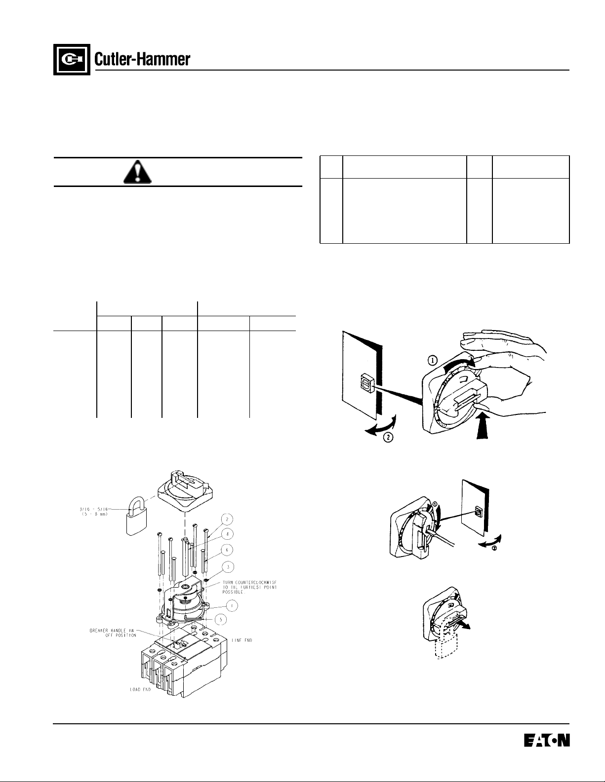
ITEM DESCRIPTION BACK
1 SHAFT SUPPORT ASSEMBLY 1 1
2 PAN HEAD SCREW 6-32 X 3.25 LG ➁ 40
3 LOCK WASHER #6 4 0
4 SHAFT 1 1
5 ALLEN WRENCH 1 1
6 HI-LO SCREW 6-19 X 1.75 LG ➂ 04
➀ For DIN Rail or Snap-In Base Plate Application, carefully remove the exist-
ing cover screws from the circuit breaker without breaking the catalog warranty nameplate and replace with Item 6.
➁ Do not exceed a torque of 2.0 lb.-in.
➂ Do not exceed a torque of 4.0 lb.-in.
DINRAIL OR SNAP-IN
PAN
BASE PLATE ➀
HANDLE FEATURES
Handle Off - Open or Close Enclosure
Effective November 1997
Handle On - Open or Close Enclosure
Lock Handle Off With Enclosure Door Interlock
➀
➁
Page 2
Page 2
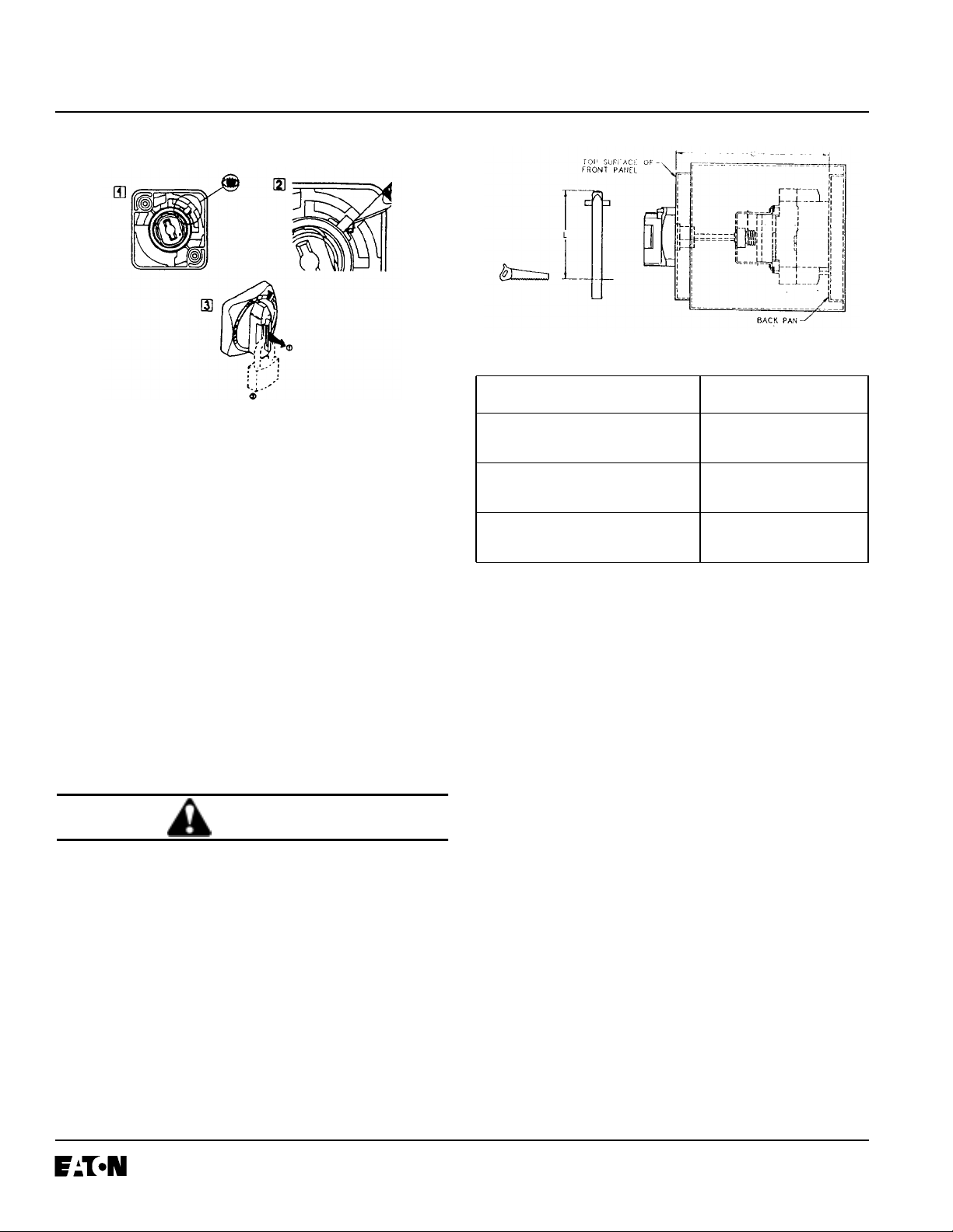
Lock Handle On With Enclosure Door Interlock
I.L. 15569C
2. Cut shaft to length.
BREAKER MOUNTING LENGTH OF SHAFT
INSTALLATION INSTRUCTIONS
1. Place circuit breaker in off position. Position the shaft
support assembly in the Off position by turning the
mechanism counterclockwise until at a solid stop.
Place the mechanism onto the circuit breaker such
that the slot on the slider on the mechanism mates
into the breaker handle. Mount the breaker and
mechanism per the customer's application using the
necessary hardware (as shown in the chart on page
1). Evenly tighten the screws to the giv en torques (as
shown below chart on page 1).
NOTE: Before mounting the shaft support assembly
and breaker to the back pan, see installation instruction item 4 to be certain to acquire minimum front
panel dimensions for door clearance.
If mounting the breaker directly to the back of the
pan, see the figure on page 1 for mounting hole
dimensions.
CAUTION
BE CERTAIN TO CORRECTLY ASSEMBLE SHAFT
SUPPORT TO THE CIRCUIT BREAKER. FAILURE TO
DO THIS WILL CAUSE IMPROPER OPERATION AND
BREAKAGE OF PANS.
DO NOT EXCEED TORQUE LIMITS ON SCREWS.
HIGHER TORQUES COULD CAUSE CRACKING ON
THE SHAFT SUPPORT ASSEMBLY AND IMPROPER
OPERATION.
SCREW INTO BACK PAN L = C -106
L = C - 4 3/16 IN.
DIN RAIL L = C -119 MM
L = C - 4 11/16 IN.
SNAP-IN BASE PLATE L = C -108 MM
L = C - 4 1/4 IN.
Note: Dimension C is the measurement from the back
pan to the top surface of the front panel.
3. Place the shaft into the shaft support assembly as
shown on page 1 and tighten the set screw on the
collar.
4. Measure the distance from the hinge to the center of
the shaft. Measure the distance perpendicular to the
last measurement from the center of the shaft to one
of the sides of the enclosure. With the front panel
door open, mark the inside panel door with these
measurements and drill a 5/16 Dia. hole. Carefully
close the panel door and check to see if the hole is
center to shaft. From inspection of the 5/16 dia. hole,
drill a 3/8 Dia. (35mm) hole.
MM
Effective November 1997
Page 3

I.L. 15569C
Page 3
5. After drilling, close the door of the front panel and
place the full size cutout template on the front panel.
Center the template over the shaft and align the top
edge of the template so that it is parallel with the line
end of the breaker . Mark the handle screw holes and
drill (2) 7/32 Dia. (5.5mm) holes as indicated on the
template.
6. Apply the mounting screws to door and handle.
7. With main power Off, check the mechanism opera-
tion in the On, Off, and reset positions.
Effective November 1997
Page 4

Page 4
I.L. 15569C
Cutler-Hammer
Pittsburgh, Pennsylania U.S.A.
Style No. 8698C43H04 Effective November 1997
Printed in U.S.A./CCI
 Loading...