

Page 1
Installation Instructions
Instrucciones de montaje
Notice d’installation
Montageanweisung
Istruzioni per il montaggio
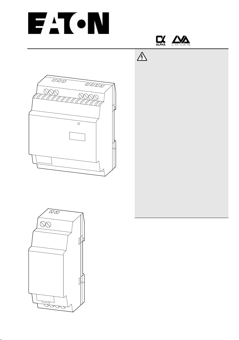
EZ200-POW
EZ400-POW
Power
Electric current! Danger to life!
Only skilled or instructed persons may carry
out the following operations.
The power supply units are mounting devices.
The national regulations/specifications must be
observed for the installation of the devices.
¡Corriente eléctrica! ¡Peligro de muerte!
El trabajo a continuación descrito debe ser realizado
por personas cualificadas y advertidas. Las fuentes de
alimentación son aparatos de montaje. Para la
instalación de los aparatos han de tenerse en cuenta
las normativas/especificaciones a nivel local.
Tension électrique dangereuse !
Seules les personnes qualifiées et averties doivent
exécuter les travaux ci-après. Les blocs d’alimentation
sont des appareils faisant partie intégrante d’une
installation. Veuillez respecter les normes de mise en
œuvre spécifiques aux différents pays.
Lebensgefahr durch elektrischen Strom!
Nur Elektrofachkräfte und elektrotechnisch
unterwiesene Personen dürfen die im Folgenden
beschriebenen Arbeiten ausführen.
Die Stromversorgungsgeräte sind Einbaugeräte.
Beachten Sie für die Installation der Geräte die
länderspezifischen Vorschriften.
Tensione elettrica: Pericolo di morte!
Solo persone abilitate e qualificate possono eseguire
le operazioni di seguito riportate. Gli alimentatori
sono unità per montaggio interno. Per l’installazione
degli apparecchi è necessario rispettare le normative
specifiche di ciascun paese.
IL05013008E 1/8
Page 2
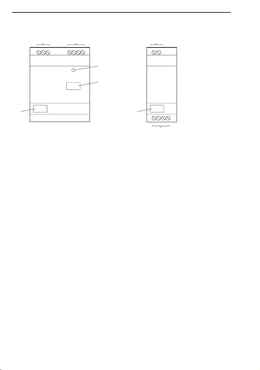
Front view – Vista de frente – Face avant – Frontansicht – Vista frontale
EZ400-POW EZ200-POW
a
b
a
d
c
c
a Main voltage supply 85 to 264 V~
b Output voltage U
U
= 12 V H EZ200-POW
e2
c Device label
d Status display Power-LED
On continuous light: Mains voltage and 24 V H present
Off: No mains voltage
a Alimentación de tensión de la red 85 a 264 V~
b Tensión de salida U
U
= 12 V H EZ200-POW
e2
c Placa indicadora
d LED Alimentación pantalla de estado
Luz continua conectada:
existe tensión de red y 24 V H
Off: no existe tensión de red
a Alimentation réseau 85 à 264 V~
b Tension de sortie U
U
= 12 V H EZ200-POW
e2
c Identification d’appareils
d Affichage d’état Power-LED
Allumée en permanence :
Présence tension réseau et 24 V H
Eteinte : Absence tension de réseau
= 24 V H /
e
Error on output
= 24 V H /
e
error en al salida
= 24 V H /
e
Défaut sur sortie
c
b
a Netzspannungsversorgung 85 bis 264 V~
b Ausgangsspannung U
U
= 12 V H EZ200-POW
e2
c Gerätekennzeichnung
d Statusanzeige Power-LED
An-Dauerlicht: Netzspannung und 24 V H vorhanden
Aus: keine Netzspannung
Fehler am Ausgang
a Alimentazione 85 a 264 V~
b Tensione di uscita U
U
= 12 V H EZ200-POW
e2
c Siglatura apparecchio
d Visualizzazione di stato LED Power
ON acceso: tensione di rete e 24 V H disponibili
Off: manca tensione
errore sull’uscita
= 24 V H /
e
= 24 V H /
e
IL05013008E
2/8
Page 3
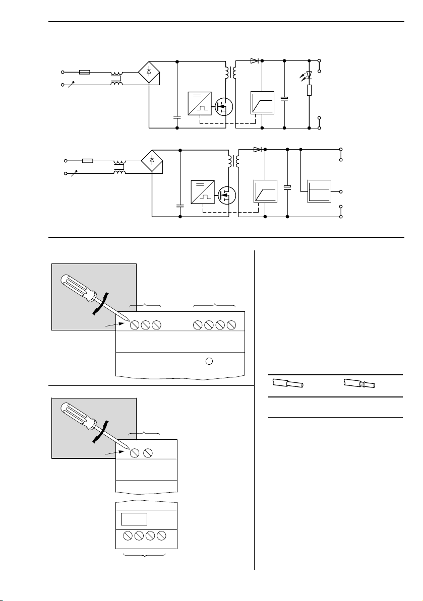
Blockdiagram – Diagrama de bloques – Schéma de principe – Prinzipschaltbild –
Schema di principio
EZ400-POW
L1
Power
+24 V
N
U
0 V
EZ200-POW
+24 V
L1
N
U U
+12 V
0 V
q SELV A VDE 0100 T 410; IEC 60364-4-41; HD 384.4.41; DIN EN 60950; IEC/CEI 950
U
e
Connections – Conexiones – Raccordements – Anschlüsse – Collegamenti
EZ400-POW
5 – 7 lb-in
IL05013008E
0.5 – 0.7 Nm
EZ200-POW
5 – 7 lb-in
0.5 – 0.7 Nm
3.5 mm
3.5 mm
a
LN
N +24V+24V0V 0V
b
AC115...240 V DC Output
a
L
N
AC115...240 V
DC
Output
+24V+12V0V 0V
b
0.2 – 4 mm
2
AWG 12 – AWG 22
0.2 – 2.5 mm
2
AWG 12 – AWG 22
3/8
Page 4

Standard connection – Conexión estándar – Raccordement standard –
Standardanschluss – Collegamento standard
EZ400-POW EZ200-POW
L
N
L+
a
L–
L
N
a
L
N +24 V 0 V
a Cable protective device/fuse: 115/230 V
Isolation acc. VDE 0100, EN 50178
a Aparato/fusible protector de cable: 115/230 V
Aislamento de acuerdo con VDE 0100, EN 50178
a Organe de protection : 115/230 V
Isolation du réseau selon VDE 0100, EN 50178
a Leitungsschutzorgan/Sicherung: 115/230 V
Freischaltung nach VDE 0100, EN 50178
a Organo di protezione/fusibile: 115/230 V
Chiusura su carico nullo secondo VDE 0100, EN 50178
Ensure cable protection and correct cross-sections!
¡Se debe tener en cuenta la protección de cables y las secciones!
Respecter la protection des lignes ainsi que les sections raccordables !
Leitungsschutz und Querschnitte beachten!
Rispettare la sezione e la protezione del cavo!
L
+24 V+12 V 0 V 0 V
L01+
L02+
L–
N
IL05013008E
4/8
Page 5

Fitting – Montaje – Montaggio – Montage – Montaje
on 35 mm top-hat rail
sobre guía semétrica de 35 mm
sur profilé-support 35 mm
auf 35-mm-Hutschiene
su guida DIN 35 mm
1
2
on mounting plate
sobre placa de montaje
sur plaque de montage
auf Montageplatte
su piastra di montaggio
EZB4-101-GF1
CLICK !
IL05013008E
EZ400-POW EZ200-POW
5/8
Page 6

Mounting position – Posición de montaje – Position de montage – Einbaulage –
Posizione di montaggio
with top-hat rail (horizontal and vertical)
sobre carril (horizontal y vertical)
sur profilé chapeau (horizontale et verticale)
mit Hutschiene (waagerecht und senkrecht)
su guida DIN (orizzontale e verticale)
30
1.18“
30
1.18“
30
1.18“
30
1.18“
IL05013008E
HAZARDOUS LOCATION – CSA (Canadian Standards Association) Certification
This equipment is suitable for use in CLASS I, DIVISION 2, GROUPS A, B, C AND D
WARNING: “EXPLOSION HAZARD – DO NOT DISCONNECT WHILE CIRCUIT IS LIVE UNLESS AREA IS KNOWN
TO BE NON-HAZARDOUS“
EMPLACEMENTS DANGEREUX – Certification CSA (Canadian Standards Association)
Cet équipement est acceptable pour utilisation dans les EMPLACEMENTS DANGEREUX DE CLASSE I, DIVISION 2,
GROUPES A, B, C ET D
AVERTISSEMENT : « RISQUE D’EXPLOSION. NE PAS DÉBRANCHER TANT QUE LE CIRCUIT EST SOUS TENSION,
A MOINS QU’IL NE S’AGISSE D’UN EMPLACEMENT NON DANGEREUX »
6/8
Page 7

EZ400-POW
24 V H
I
100 %
100 %
50 %
EZ200-POW
24 V H
I
100 %
100 %
50 %
IL05013008E
U
b Overload
c Short-circuit
a Normal operation
t
=Retry time
e
t
=Pause time
t
etp
p
a Modo operativo normal
b Sobrecarga
c Cortocircuito
t
= Tiempo de arranque
e
t
= Tiempo de parada
a
b
c
p
a Fonctionnement normal
b Surcharge
c Court-circuit
t
= Temps de démarrage
e
t
= Temps de pause
p
U
a Normalbetrieb
b Überlast
c Kurzschluss
t
=Anlaufzeit
t
etp
e
t
=Pausenzeit
p
a Funzionamento normale
b Sovraccarico
c Cortocircuito
t
= Tempo di lavoro
a
b
c
e
t
= Tempo di pausa
p
12 V H
I
100 %
U
100 %
a
b
c
7/8
Page 8

Dimensions – Dimensiones – Abmessungen – Dimensioni
45 1.77“
4.5 0.177“
47.5
1.87“
56.5 2.22“
EZ400-POW EZ200-POW
10.75
0.423“
35.75
M4
1.41“
50
71.5
1.97“
8/8
Eaton Electrical
1000 Cherrington Parkway
Moon Township, PA 15108
United States
tel. 1-800-525-2000
www.EatonElectrical.com
2.81“
3.54“
90
4.02“
102
4.33“
110
7.5 0.295“
90 3.54“
110 4.33“
102 4.02“
M4
7.5 0.295“
35.5 1.398“
© 2004 by Eaton Corporation
All Right Reserved
Printed in the Federal Republic of Germany (Dec 2004)
Form No. IL05013008E
12275160/DE13 (Eb)
IL05013008E
 Loading...