

Page 1
a
r
s
A
s
E
e
s
s
E
Applic
Diffe
PLC
tion Note
ence
P070002
betw
N
en ELC serie
Effective Ap
and
ril 2014
LC2 series
Page 2
Application Note AP070002EN Differences between ELC series and ELC2 series PLCs
Effective April 2014
Application Summary
The differences between ELC-PB and ELC2-PB; ELC-PC/PH and ELC2-PC; and ELC-PV and ELC2-PV.
Products and Revisions
Vendor Product Applicable Revision Tested Revision
Eaton ELC-PA/PB/PC/PH/PV
Eaton ELC2-PA/PB/PC/PE/PV
Supporting Documentation
Manual Name Reference Number
Operation Manual ELC MN05003006E
Programming Manual ELC MN05003003E
Introduction:
ELC2 is the newer version PLC in Eaton ELC series. There are some hardware differences between ELC
and ELC2 PLCs. This application note shows these differences in I/O terminals, wiring, memory maps
and other technical specifications. Other changes and differences between the ELC and ELC2 are
summarized below:
The ELC2 models are 32-bit CPUs vs the ELCs that are 16-bit CPUs so they are faster and more
powerful
The ELC-PC12NNAR has been obsoleted and there is no ELC2 replacement for this CPU
The ELC-PA10AADR and ELC-PA10AADT will remain as being available as 16-bit controllers be-
cause of their 37mm width
The ELC2-PA20 is a new addition which is 70mm wide and consisting of the ELC2-PA20AADR,
ELC2-PA20AADP and ELC2-PA20AADT
All of the ELC2-PC controllers include high-speed 100kHz inputs as standard
The ELC-PH will be replaced by an ELC2-PC model as there is no need to have separate high-
speed input models
The ELC2-PE is a new CPU model (37mm wide) with on-board Ethernet communications consisting
of the ELC2-PE12NNDR and ELC2-PE12NNDT
New PNP transistor output models for the ELC2-PB and ELC2-PV are available consisting of the
ELC2-PB12NNDP (12 vs 14 I/O - 8I/6O) and ELC2-PV28NNDP
Page 3
●
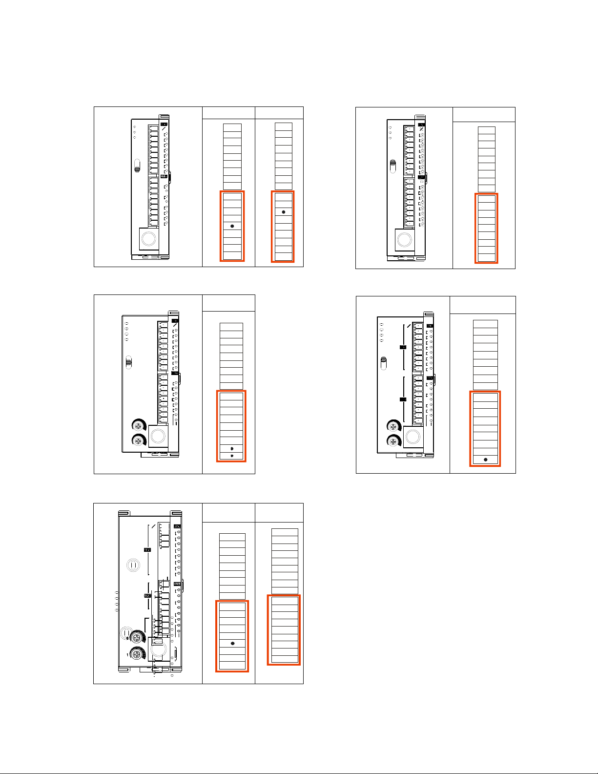
1. The difference in output terminals between ELC and ELC2 models.
ELC2-PB ELC-PB
R T
POWER
RUN
ERROR
RUN
STOP
ELC2-PB14NNDR
s
s
X0
0
X1
1
X2
2
X3
3
X4
4
X5
5
X6
6
X7
7
C0
Y0
0
Y1
Y2
1
●
C1
2
Y3
3
Y4
4
Y5
5
S/ S
X0
X1
X2
X3
X4
X5
X6
X7
C0
Y0
Y1
Y2
C1
Y3
Y4
Y5
S/ S
X0
X1
X2
X3
X4
X5
X6
X7
UP
ZP
Y0
Y1
Y2
Y3
Y4
Y5
POWER
RUN
ERROR
RUN
STOP
ELC-PB14NNDR
ELC-PC ELC-PH
R/T
POWER
BAT.LOW
RUN
STOP
0
1
RUN
ERROR
ELC-PC12NNDR
s
s
X0
X1
X2
X3
X4
X5
X6
X7
C0
Y0
C1
Y1
C2
Y2
Y3
RS-232
RS-485
S/S
X0
X1
X2
X3
X4
X5
X6
X7
C0
Y0
C1
Y1
C2
Y2
Y3
POWER
RUN
ERROR
BAT.LOW
RUN
STOP
ELC-PH12NNDT
0
1
ELC2-PC
R T
POWER
s
s
RUN
X0
X1
X2
X3
X4
X5
X6
X7
C0
Y0
Y1
Y2
Y3
SG
COM1
X0
X1
X2
X3
X4
X5
X6
X7
Y0
Y1
Y2
Y3
COM3
COM2
S/S
X0
X1
X2
X3
X4
X5
X6
X7
C0
Y0
Y1
Y2
Y3
SG
COM3+
COM3-
ERROR
COM1
RUN
STO
COM3+
COM3-
S/S
X0
X1
X2
X3
X4
X5
X6
X7
Y0
Y1
Y2
Y3
UP
ZP
SG
COM3+
COM3-
R/T
S/S
X0
X1
X2
X3
X4
X5
X6
X7
C0
Y0
C1
Y1
C2
Y2
Y3
Y4
Y5
T
s
s
s
s
X0
X0
X0
X1
X1
X1
X2
X2
X2
X3
X3
X3
X4
X4
X4
X5
X5
X5
X10
X10
X10
X11
X11
X11
C0
C0
Y0
Y0
Y0
C1
C1
Y1
Y1
Y1
C2
C2
Y10
Y10
Y10
C3
C3
Y11
Y11
Y11
●
●
RS-232
RS-485
S/S
X0
X1
X2
X3
X4
X5
X6
X7
C0
Y0
C1
Y1
C2
Y10
C3
Y11
Page 4

2. The difference in output wiring between ELC and ELC2 models.
Relay Transistor
ELC-PB
ELC2-PB
ELC-PC
ELC-PH
Relay Transistor
ELC2-PC
Page 5

3. The difference in specification between ELC-PB and ELC2-PB.
Module name ELC-PB ELC2-PB
CPU type 16-bit 32-bit
Program size 3972 steps 7920 steps
D device size 600 words (latched 192) 5000 words (latched 2100)
LD execution time 3.8 us 0.76 us
High-speed input 10KHz x 4 points 10KHz x 8 points
High-speed output 10KHz x 2 points (Y0, Y1) 10KHz x 4 points (Y0~Y3)
Total bandwidth 40KHz (X0~X3, Y0, Y1) None
DHSCS/DHSCR 4 comparators 6 comparators
External interrupt 4 points (rising edge) 8 points (rising / falling edge)
New major functions added to ELC2-PB:
PLSY, PWM, PLSR can be selected to output Y2 and Y3. DDRVI, DDRVA, and DZRN are
supported.
COM1 can be used in a master mode, and it can receive a GPS protocol (device mode).
Page 6

4. The difference in specification between ELC-PC/PH and ELC2-PC.
Module name ELC-PC/PH ELC2-PC
CPU type 16-bit 32-bit
Program size 7920 steps 15872 steps
D device size 5000 words (latched 3800) 10000 words (latched 2100)
File register 1600 5000
Battery Yes None
LD execution time 3.8 us 0.76us
High-speed input 10KHz x 6, 100KHz x 2 points 10KHz x 6, 100KHz x 2 points
High-speed output 10KHz x 2, 100KHz x 1 point 10KHz x 2, 100KHz x 2 points
Total bandwidth
40KHz (X0~X5, Y0, Y1), 130KHz
(X10,X11, Y10, Y11)
None
RS485 port 1 2
Left side interface None Support
External interrupt 6 points (rising edge) 8 points (rising / falling edge)
New major functions added to ELC2-PC:
COM1 and COM3 can be used in a master mode, and COM1 can receive a GPS protocol (de-
vice mode).
New solar tracking instruction: DSPA
After 24V power is OFF, the RTC can still keep track of time for 7 days without a battery.
One 2-axis synchronized positioning control (linear and arc interpolation).
The frequency with which an A/B phase output is produced can be up to 50 KHz.
Page 7

5. The difference in specification between ELC-PV and ELC2-PV.
Module name ELC-PV ELC2-PV
CPU type 16-bit 32-bit
Program size 15872 steps 30000 steps
D device size 10000 words 12000 words
File register 10000 words 50000 words
API execution time slower 4 times faster than ELC
6. There are many new instructions for ELC2 series:
Basic instructions can be used to manipulate the bits in a word device, e.g. BLD D0 K7 (LD
D0.7)
Basic instructions can be used with index devices, e.g. LD X0E1
Floating-point comparison input instruction: FLD>, FLD>=, FLD< ……
Page 8

7. The ELC vs ELC2 memory maps.
The ELC2 memory map is different from the ELC memory map – except the ELC2-PV, which is
the same as the ELC-PV; the differences are listed below:
Non Latched Area Latched Area
Device
ELC-PB ELC2-PB ELC-PB ELC2-PB
S None S128~S911 S0~S127
M M0~M511
D D0~D407
M0~M511,
M768~M999
M2000~M2047
D0~D407,
D600~D999,
D3920~D4999
M512~M767
D408~D599
S0~S127,
S912~S1023
M512~M767,
M2048~M4095
D408~D599
D2000~D3919
Non Latched Area Latched Area
Device
ELC-PB ELC2-PB ELC-PB ELC2-PB
100
T
(ms)
C
(Bit)
T0~T63
T64~T126 T200~T245 None None
10
T127 T127, T246~T249 None None
1
C0~C111
16
None C200~C223 C235~C255 C224~C255
32
T0~T126
T128~T199
T250~T255
C0~C111
C128~C199
None None
C112~C127 C112~C127
Non Latched Area Latched Area
Device
ELC-PA/PC/PH ELC2-PA/PC ELC-PA/PC/PH ELC2-PA/PC
S S0~S511 S128~S911 S512~S1023
M M0~M511
D D0~D199
100
T
(ms)
T0~T199,
T250~T255
T200~T245 T200~T245 None None
10
M0~M511,
M768~M999
M2000~M2047
D0~D407,
D600~D999,
D3920~D9999
T0~T126
T128~T199
T250~T255
M512~M999
M2000~M4095
D200~D999
D2000~D4999
None None
S0~S127,
S912~S1023
M512~M767,
M2048~M4095
D408~D599
D2000~D3919
T246~T249 T127, T246~T249 None None
1
C0~C95
C
(Bit)
16
C200~C215 C200~C223 C216~C255 C224~C255
32
C0~C111
C128~C199
C96~C199 C112~C127
Page 9

8. Introduction of the ELC2-PA20 module.
8.1 I/O configuration of a terminal block
R T(NPN) P(PNP)
ELC2-PA20AADR
POWER
RUN
ERROR
USB
RS-232
RS-485
0
1
2
3
4
5 5
6
7
V0
+
I0
+
VI0
V1
+
I1
+
VI1
V2
+
I2
+
0
VI2
1
V3
2
+
3
I3
+
VI3
4
FE
VO0
IO0
VO1
IO1
AG
X0
X1
X2
X3
X4
X5
X6
X7
C0
Y0
Y1
Y2
C1
Y3
Y4
Y5
V0+
I0+
VI0V1+
I1+
VI1V2+
I2+
VI2-
V3+
I3+
VI3-
FE
VO0
VO1
IO1
AG
S/S
X0
X1
X2
X3
X4
X5
X6
X7
C0
Y0
Y1
Y2
C1IO0
Y3
Y4
Y5
V0+
S/S
I0+
X0
VI0-
X1
V1+
X2
I1+
X3
VI1-
X4
V2+
X5
I2+
X6
VI2-
X7
V3+
UP
I3+
ZP
VI3-
Y0
FE
Y1
Y2
VO0
Y3IO0
VO1
Y4
IO1
Y5
AG
8.2 Major specification
Module name
(4DI + 2DO + 2AI + 2AO)
ELC-PA10
CPU type 16-bit 32-bit
Program size 7920 steps 15872 steps
V0+
S/S
I0+
X0
VI0-
X1
V1+
X2
I1+
X3
VI1-
X4
V2+
X5
I2+
X6
VI2-
X7
V3+
UP
I3+
ZP
VI3-
Y0
FE
Y1
Y2
VO0
Y3IO0
VO1
Y4
IO1
Y5
AG
ELC2-PA20
(8DI + 6DO + 4AI + 2AO)
D device size 5000 words (latched 3800) 10000 words (latched 2100)
File register 1600 5000
Battery Yes None
LD executing time 3.8 us 0.76us
High-speed input 10KHz x 2, 20KHz x 2 points 10KHz x 6, 100KHz x 2 points
High-speed output 10KHz x 2 point 10KHz x 2, 100KHz x 2 points
Total bandwidth 40KHz (X0~X3, Y0, Y1), None
USB port None Support
Left side interface None Support
External interrupt 6 points (rising edge) 8 points (rising / falling edge)
8.3 ELC2-PA’s memory map, function and instructions are same as ELC2-PC’s.
After 24V power is OFF, the RTC can still keep track of time for 7 days without a battery.
One 2-axis synchronized positioning control (linear and arc interpolation).
Page 10

o
3
n
t
A
s
p
p
C
T
o
c
o
c
t
e
P
A
e
v
A
8
A
w
R
/
e
a
a
e
Additi
In the US
or 1-877-
Locatio
United S
Canada
Europe
ll other
nal Hel
or Canada:
26-2273.
ates
upporting d
lease conta
ontact
echnical Res
cumentation
t the Techni
urce Center a
is located on
al Resource
1-877-ETN-C
the Eaton w
Center at 1-
RE or 1-877-
b site at ww
77-ETN-CA
326-2273.
.eaton.com
E
plc
Eaton
1000 Eaton Boule
Cleveland, OH 44
Eaton.com
© 2014 Eaton
All Rights Reserv
Printed in USA
Publication No. A
April 2014
ard
122 US
d
070002EN
Eaton is a regist
of Eaton Corpor
All other tradem
of their respectiv
red trademark
tion.
rks are property
owners
 Loading...