

Page 1
Manual
easyE4
04/19 MN050009 EN
Page 2

Imprint
All brand
owners.
Original Operating Instructions
is the German-language edition of this document
Publication date
04/19 MN050009 EN 2.0 Edition, Build 008
Copyright
© 2018 by Eaton Industries GmbH, 53105 Bonn
Author: Electrical Sector, Business Unit MOC
Editor:
Eaton Industries GmbH, Hein-Moeller-Straße 7-11, D-53115 Bonn
All rights, including those of translation, reserved.
No part of this manual may be reproduced, stored in a retrieval system, or transmitted in any
form or by any means, whether electronic, mechanical, photocopying, micro-filming,
recording, or otherwise, without the prior written permission of Eaton Industries GmbH, Bonn.
and
product
names
are
trademarks or registered trademarks of their respective
Subject to alteration.
Page 3

DANGER!
Dangerous ElectricalVoltage!
Before starting with the installation
l Installationrequires qualified electrician
l Disconnectthe power supply of the device.
l Secure against retriggering
l Verify isolationfrom thesupply
l Groundandshort-circuit
l Cover or enclose any
neighboringlive parts.
l Follow the engineering instructions (IL) of the device
concerned.
l Only suitably qualified personnel inaccordance with
EN 50110-1/-2 (VDE 0105 part 100) may work on this
device/system.
l Beforeinstallationandbeforetouchingthe device
ensure that you are freeof electrostatic charge.
l Thefunctional earth (FE) must be connected tothe
protective earth (PE) or to theequipotential bonding.
Thesystem installer is responsiblefor implementing
this connection.
l Connectingcables andsignallines should be
installed so that inductive or capacitive interference
does not impair the automation functions.
l Installautomation devices and relatedoperatingele-
ments in sucha way thatthey are wellprotected
against unintentionaloperation.
l Suitablesafety hardware and software measures
shouldbe implemented for the I/O interfaceso that a
lineor wire breakageon the signal sidedoes not result in undefinedstates in the automation devices.
l Deviations of the mains voltage from the nominal
value must not exceed the tolerancelimits given in
the specifications, otherwise this may result in malfunctionandhazardous states.
l Emergency-Stop devices complying with IEC/EN
60204-1 must be effective inall operatingmodes of
the automation devices. Unlatching the emergency
stop devices must notresult inan automatic restart.
l Built-in devices for enclosures or cabinets must only
be run and operated in an installed state; desktop
devices andportable devices only whenthe housing
is closed.
l Measures shouldbe taken toensure the proper
restartingof programs interruptedafter a voltage dip
or outage. This should not result indangerous operating states even for a short time. If necessary, emergency stop devices should be implemented.
l Wherever faults in the automation system may
cause damage topersons or property, externalmeasures must be implemented toensure asafe operating statein the event ofa fault or malfunction (for
example,by means of separate limit switches, mechanicalinterlocks, etc.).
I
Page 4

Page 5

Table of Contents
easyE4 Manual 1
Imprint 2
Beforestarting withthe installation 3
Table of Contents 1
0.1 About this manual 13
0.1.1 List of revisions 13
0.1.2 Target group 14
0.1.3 Legal disclaimer 15
0.1.4 Short designations 16
0.1.5 Writingconventions 17
0.1.5.1 Warning labels 17
0.1.5.2 Documents with additional information 18
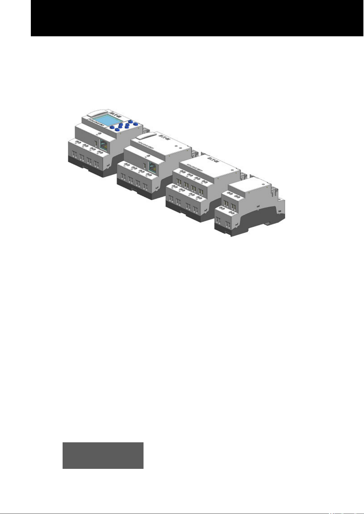
1. easyE4 control relays description 19
1.1 Use as intended 19
1.2 Function 19
1.2.1 Features 20
1.3 Device models - versions and part nos. 22
1.3.1 Basic features 22
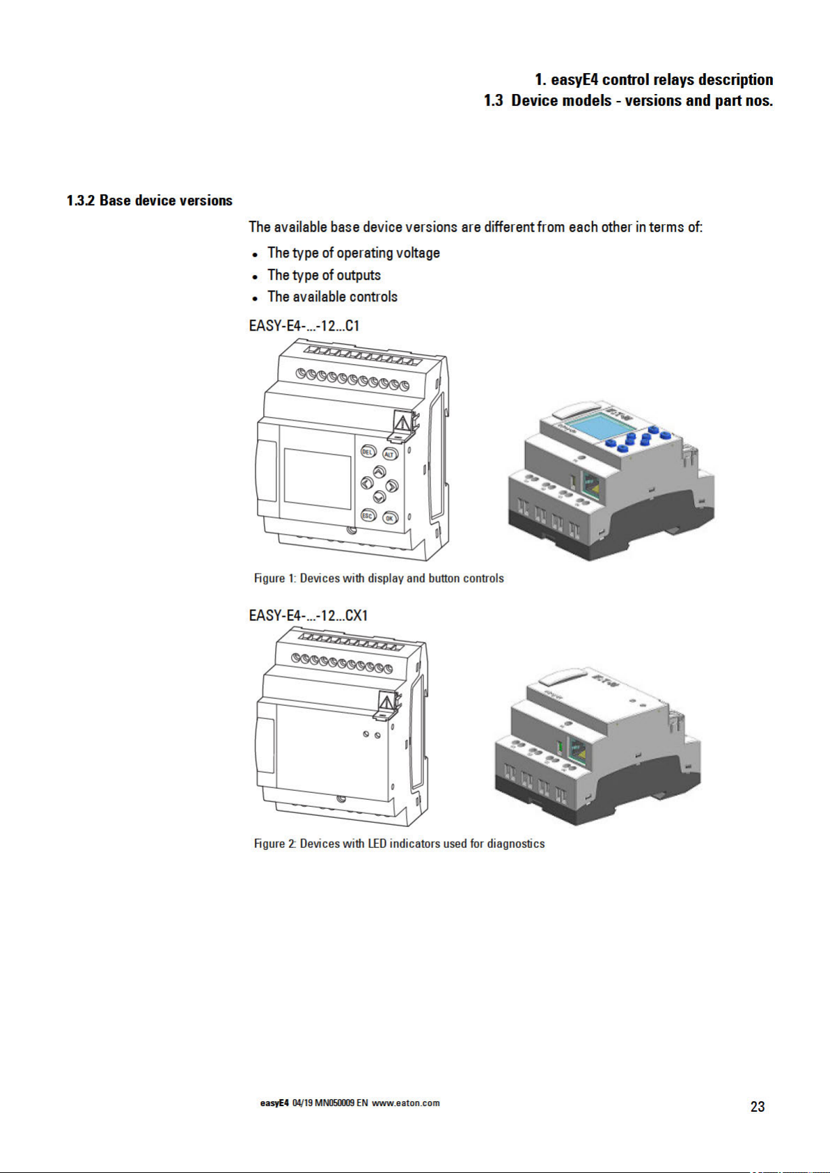
1.3.2 Base device versions 23
1.3.3 I/O expansion versions EASY-E4-...-...E1 24
1.3.3.1 Overview of available easyE4 devices 25
1.4 Accessory devices 27
1.5 What the different parts of the part number mean 27
1.6 Nameplate 28
1.7 Support 28
1.8 Overview of devices 29
1.9 Programmingsoftware easySoft 7 31
1.10 Safety regulations 32
1.10.1 Basics 32
1.10.2 Mandatory requirements, personnelrequirements 32
1.10.2.1 Occupational safety 32
easyE4 04/19 MN050009 EN
1
Page 6

1.10.2.2 Personnel qualifications 32
1.10.2.3 Device documentation 33
1.10.2.4 Installation, maintenance, anddisposal 33
1.10.2.5 Prerequisites for proper operation 34
1.10.3 Device-specifichazards 35
1.11 Engineering 38
1.11.0.1 Lengthof input cables 38
1.11.0.2 Analog signals 39
1.11.0.3 Notes onconnecting EASY-E4-AC-... devices 40
2. Installation 43
2.1 Prerequisites for the locationof use 44
2.1.1 Installationposition 44
2.1.1.1 Temperatures 44
2.1.1.2 Aeration and de-aeration 45
2.2 Unpacking and checking the equipmentsupplied 46
2.3 Mounting 47
2.3.1 Mounting easyE4 controlrelays 47
2.3.1.1 Installationon mountingrail 50
2.3.1.2 Screw mounting 52
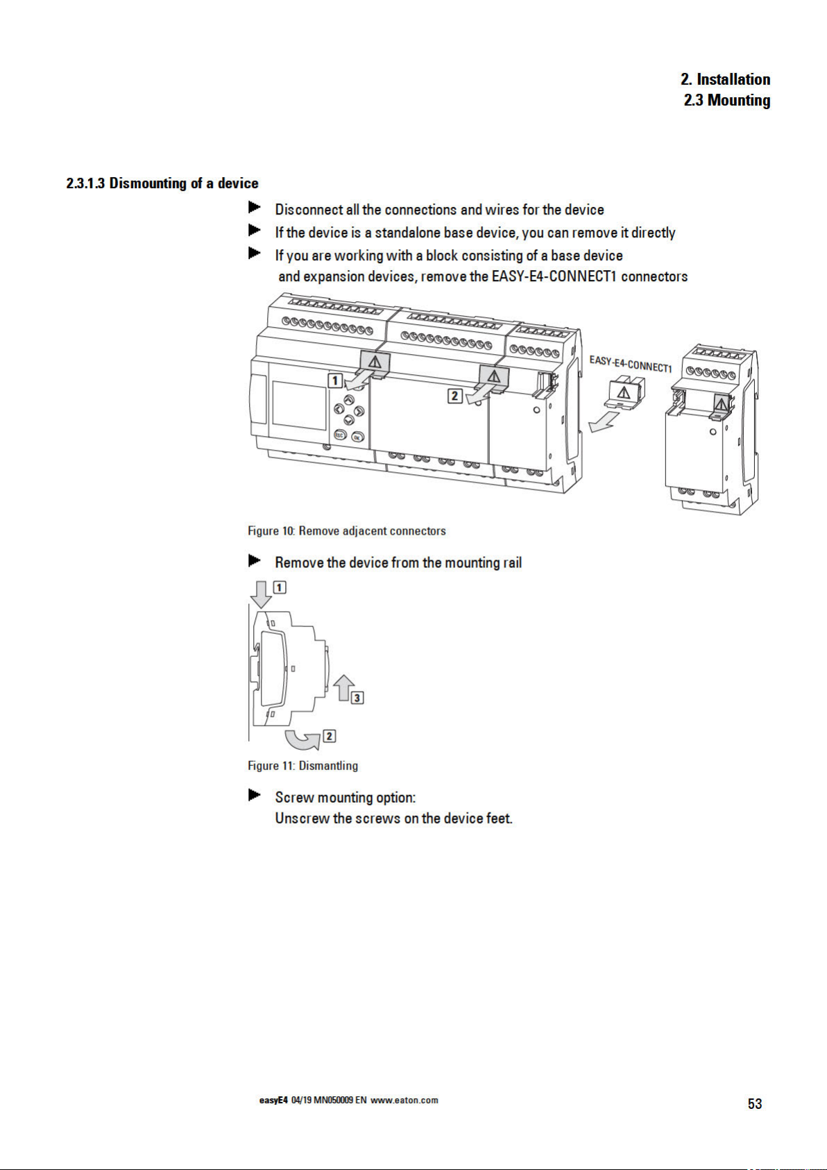
2.3.1.3 Dismounting of a device 53
2.4 Connectionterminals 54
2.4.1 Cable cross-sections 54
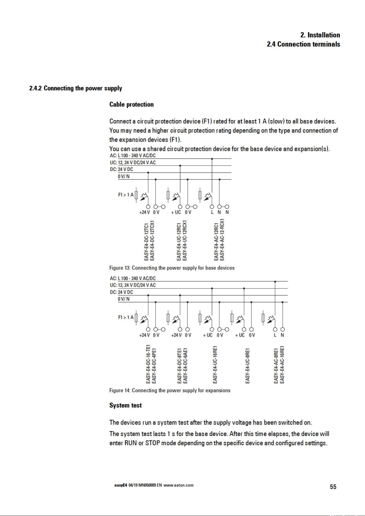
2.4.2 Connectingthe power supply 55
2.4.2.1 Specialnotes on connecting EASY-E4-AC-... devices 56
2.4.3 Connectdigital inputs 57
2.4.3.1 Connectdigital counter inputs 59
2.4.4 Connectinganalog inputs 60
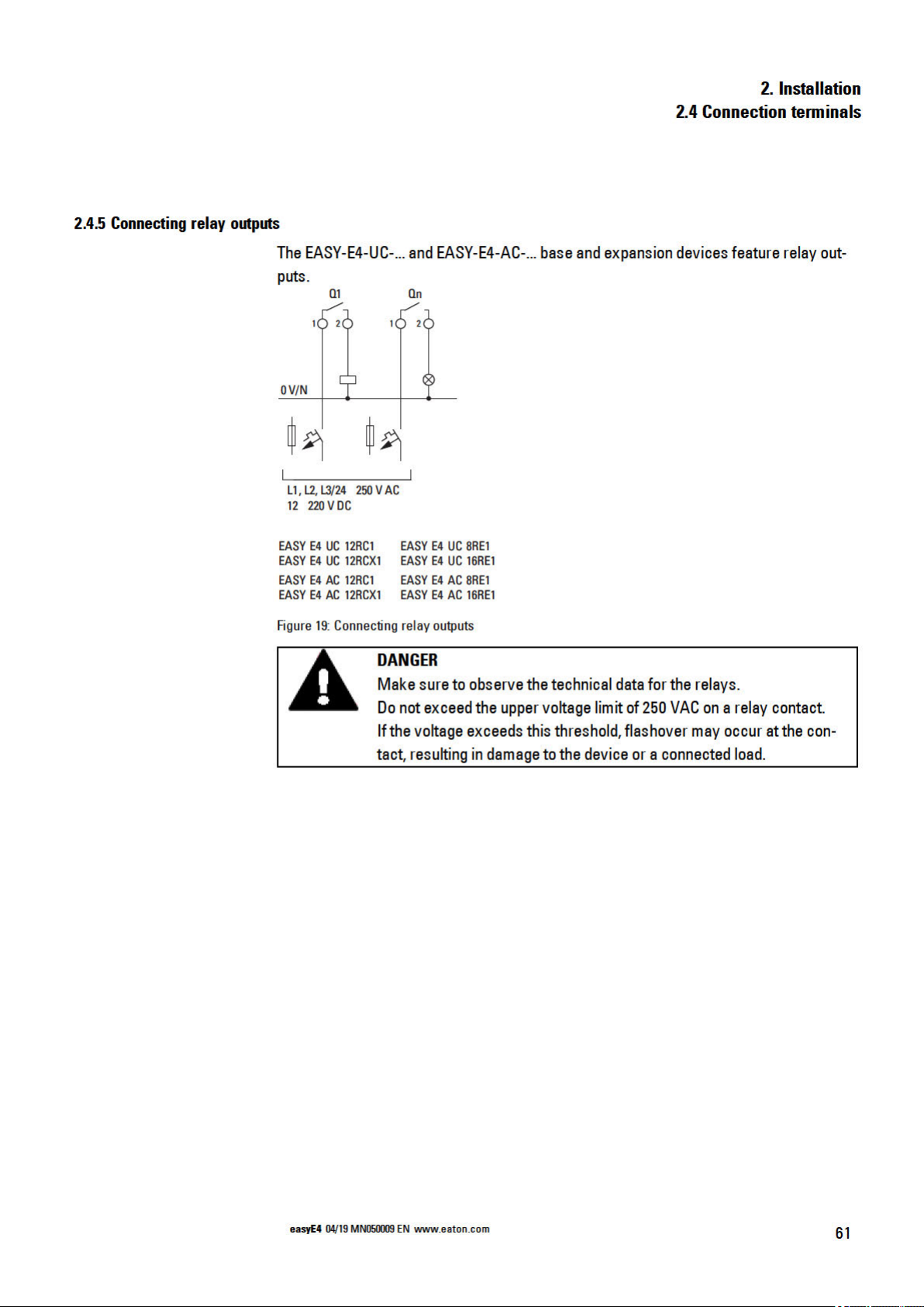
2.4.5 Connectingrelay outputs 61
2.4.6 Connectingtransistor outputs 62
2.4.6.1 Transistor output behavior in the event of a short circuit/overload64
2.4.6.2 Connectingoutputs in parallel 64
2.4.7 Analog I/O expansion device 65
2.4.8 Analog input expansion with temperature measuring 67
2
easyE4 04/19 MN050009 EN
Page 7

2.4.9 Terminal configurations for individual devices 70
2.5 Externalconnections 72
2.5.1 Externalconnectionlayouts 72
2.5.2 Memory card 73
2.5.3 Ethernet 75
2.5.3.1 Connectingthe Ethernet cable 76
2.6 Programmingsoftware license 77
2.6.1 System requirements 78
2.6.2 Licensing 78
2.6.2.1 Getting alicense key 79
2.6.3 Adding alicense key later on 80
2.6.4 Software updates andhardwarechanges 81
2.6.5 Installationinstructions 82
3. Commissioning 87
3.1 Initial commissioning 87
3.2 Daily operation 87
3.3 Switch on 88
3.3.1 Startupbehavior of easyE4 control relays with LED indicators 88
3.3.2 Startupbehavior of easyE4 control relays with a display and
keypad 90
3.3.2.1 Changing the menu language 91
3.3.3 Startupbehavior of base devices with connected expansion
devices 93
3.3.4 Status display on easyE4 controlrelays with display andkeypad 94
3.3.5 Commissioning the Ethernet network 96
3.3.5.1 Network operation 96
3.3.6 Remoteoperation 97
3.4 Overview of switch-onbehavior 98
4. Operation 101
4.1 Base device withdisplay and buttons 101
4.1.1 LCD Display 101
4.1.1.1 Display color backlight 102
4.1.2 Keyboard 102
easyE4 04/19 MN050009 EN
3
Page 8

4.1.3 Selecting menus andentering values 103
4.1.4 Cursor display 104
4.1.5 Enteringof values 104
4.2 Operatingmodes of the easyE4 105
4.2.1 RUN mode 105
4.2.2 STOP mode 105
4.3 Operationof themenu selection and value entry 107
4.3.1 How to navigate the device menus 107
4.3.2 Operatingprinciplein the circuit diagram and function block
editor 107
4.3.3 Selecting adevicemenu 108
4.4 Overview of themenus onthe device 109
4.4.1 Mainmenu 109
4.4.2 STOP RUN operating modemenu 109
4.4.3 MenuParameter 110
4.4.4 Set clock menu 111
4.4.5 MenuCard 112
4.4.6 MenuInformation 113
4.4.7 System options menu 114
4.4.8 Program menu 116
4.5 Your first EDP program 118
4.5.1 Draw a wiring diagram 120
4.5.2 Testingthe circuit diagram 123
4.5.3 Control options in RUN mode 124
4.5.4 Delete Program 126
4.6 Transfer program tothe easyE4 device 127
4.6.1 Transfer with a microSD memory card 127
4.6.2 Establish Ethernetconnection 132
5. Programming on the device 135
5.1 Program 135
5.2 Circuit diagram display 136
5.3 Circuit diagram elements 138
5.3.1 Function blocks 138
5.3.2 Relays 138
4
easyE4 04/19 MN050009 EN
Page 9

5.3.3 Contacts 139
5.3.4 Coils 140
5.3.5 Markers andanalog operands 145
5.4 Working with contacts andcoils 147
5.4.1 Enteringand modifying contacts 148
5.4.2 Changing an N/O contact to anN/C contact 149
5.4.3 Enteringand modifying coils 150
5.4.4 Deletingcontacts and coils 151
5.4.5 Creating and modifyingconnections 152
5.4.6 Deletingconnections 153
5.4.7 Adding arung 153
5.4.8 Deletinga rung 153
5.4.9 Got toa rung 154
5.4.10 Savingthe circuit diagram 154
5.4.11 Exitingthe circuitdiagram without saving 155
5.4.12 Searching for contacts and coils 155
5.4.13 Switching with the Cursor Buttons 156
5.4.14 Checking the circuit diagram 157
5.4.15 Jumps 158
5.4.16 WiringNET operands inthe circuit diagram 160
5.5 Transferring programs from and toa memory card 164
5.5.1 Configurationon base devices with a display 165
5.5.1.1 PROGRAM submenu 166
5.6 Working with function blocks 168
5.6.1 Adding functionblocks to the circuit diagram for thefirst time 168
5.6.2 Function block list 170
5.6.3 Configuring parameters inthe functionblock editor 171
5.6.4 PARAMETERS menu 174
5.6.5 Deletingfunction blocks 174
5.7 Organizing marker ranges 177
6. Function blocks 180
6.1 Manufacturer functionblocks 182
6.1.1 Timer modules 182
easyE4 04/19 MN050009 EN
5
Page 10

6.1.1.1 HW - 7-day time switch(Hour Week) 182
6.1.1.2 HY - Year time switch (Hora Year) 192
6.1.1.3 OT - Operating hours counter 202
6.1.1.4 RC - Real-time clock 206
6.1.1.5 T - Timingrelay 210
6.1.1.6 YT - Year time switch (Year Table) 225
6.1.1.7 WT - Weekly timer (WeekTable) 232
6.1.1.8 AC - Astronomic clock 236
6.1.2 Counter Function Blocks 245
6.1.2.1 C - Counter relay 245
6.1.2.2 CF - Frequency counter 251
6.1.2.3 CH - High-speedcounter 257
6.1.2.4 CI - Incremental Counter 263
6.1.3 Arithmeticandanalog function blocks 270
6.1.3.1 A - Analogvalue comparator 270
6.1.3.2 AR - Arithmetic 277
6.1.3.3 AV - Average 282
6.1.3.4 CP –Comparator 291
6.1.3.5 LS - Value scaling 295
6.1.3.6 MM - Min-/Max function 300
6.1.3.7 PM - Performance map 303
6.1.3.8 PW - Pulse widthmodulation 309
6.1.4 Open-loopandclosed-loopfunctionblocks 315
6.1.4.1 DC - PID controller 315
6.1.4.2 FT - PT1-Signalsmoothing filter 323
6.1.4.3 PO - Pulse output 329
6.1.4.4 TC - Three step controller 342
6.1.4.5 VC - Valuelimitation 347
6.1.5 Data and register function blocks 351
6.1.5.1 BC - Block compare 351
6.1.5.2 BT - Block transfer 358
6.1.5.3 DB - Datafunctionblock 364
6.1.5.4 MX - Data multiplexer 369
6.1.5.5 RE - Reciperecords 373
6
easyE4 04/19 MN050009 EN
Page 11

6.1.5.6 SR - Shift register 378
6.1.5.7 TB - Table function 386
6.1.6 NET Function blocks 391
6.1.6.1 GT - Get values from NET 391
6.1.6.2 PT - Put values to NET 395
6.1.6.3 SC - Synchronizingclock via NET 399
6.1.7 Other functionblocks 403
6.1.7.1 AL - Alarm function block 403
6.1.7.2 BV - Boolean operation 407
6.1.7.3 D - Text display 411
6.1.7.4 D - Text display editor 421
6.1.7.5 DL - Data logger 438
6.1.7.6 JC - Conditional jump 449
6.1.7.7 LB - Jump label 454
6.1.7.8 MR - MasterReset 456
6.1.7.9 NC - Numerical converter 460
6.1.7.10 ST - Set cycletime 466
6.2 interrupt functionblocks 469
6.2.1 IC - Counter-controlled interrupt 469
6.2.1.1 General 469
6.2.1.2 Operatingprinciple 470
6.2.1.3 Thefunctionblock and its parameters 471
6.2.1.4 Other 474
6.2.2 IE - Edge-controlled interrupt 482
6.2.2.1 General 482
6.2.2.2 Operatingprinciple 483
6.2.2.3 Thefunctionblock and its parameters 484
6.2.2.4 Other 486
6.2.3 IT - Time-controlled interrupt function block 488
6.2.3.1 General 488
6.2.3.2 Operatingprinciple 488
6.2.3.3 Thefunctionblock and its parameters 490
6.2.3.4 Other 492
6.3 UF - User functionblock 496
easyE4 04/19 MN050009 EN
7
Page 12

6.3.1 General 496
6.3.1.1 General information on user functionblocks 497
6.3.2 Creating a user function block 497
6.3.3 Configuring a user function block 499
6.3.4 Programminga user function block 503
6.3.4.1 Programmingview tabs 504
6.3.5 Callinga user function block inthe main program 504
6.3.5.1 User functionblocks in anST mainprogram 508
6.3.6 Savinga user function block 509
6.3.7 Exporting auser functionblock 511
6.3.7.1 Plausibility check 512
6.3.8 Importinga user functionblock 513
6.3.9 Replacing a user function block 514
6.3.10 Deletinga user function block 514
6.3.11 Comparing user function blocks 515
6.3.12 Printing a user function block 517
6.4 Timingandcounter relay example 518
7. System settings 523
7.1 System options - Base device withdisplay and buttons 524
7.2 Display 525
7.3 Device ID 525
7.4 Splash screen 526
7.5 NET 527
7.6 Ethernet 528
7.7 Update 529
7.8 Switch languages 530
7.8.1 Selecting amenu language on abase device witha display 530
7.8.2 Setting the menu language inthe easySoft 7 530
7.9 Setting the startup behavior 531
7.9.1 Enabling /disabling the RUN START option 531
7.9.1.1 Configurationon abase devicewith a display 531
7.9.2 Enabling /disabling the CARD START option 532
7.9.2.1 Configurationon abase devicewith a display 532
8
easyE4 04/19 MN050009 EN
Page 13

7.9.2.2 Configuring the easySoft 7 533
7.10 Debounce 534
7.10.1 Configuring input debouncingon abase device with adisplay 534
7.10.2 Configuring input debouncingin easySoft 7 534
7.11 Download comments 535
7.12 P buttons 536
7.12.1 Configuring the P buttons ona base device with adisplay 536
7.12.2 Configuring the P buttons in easySoft 7 536
7.13 Define program name 537
7.14 Retention function 538
7.14.1 Retention inthe easySoft 7 539
7.15 Security – password protection 541
7.15.1 Configuring the password ona base device witha display 541
7.15.1.1 What happens if you forgetyour password or enter the wrong
password? 543
7.15.2 Configuring the password ineasySoft 7 544
7.16 Configuring the memory cardand device ID 546
7.17 Time and Date setting 547
7.17.1 Time and date on a base device witha display 547
7.17.2 Setting time and date in theeasySoft 7 550
8. microSD memory card 553
8.1 Automatic booting from the card 553
8.1.1 Preparingthe card in the PCfor booting witheasySoft 7 554
8.1.1.1 Transfer program 555
8.1.1.2 Setting aprogram as the starting program 557
8.1.2 Preparingthe card in the easyE4 device for booting with
easySoft 7 558
8.1.2.1 Transfer program 560
8.1.2.2 Setting aprogram as the starting program 561
8.1.3 Preparingthe card for booting on the easyE4 device itself 562
8.2 Reset –resettingthe deviceto factory settings 564
8.3 Loading the new operating system - from OS version 1.10 565
8.3.1 Firmware update Basisgerät 566
8.3.2 Firmware update expansiondevice 568
easyE4 04/19 MN050009 EN
9
Page 14

8.3.2.1 An expansionis updated from the base device withdisplay 569
8.4 Loading the new operating system - up toOS version 1.00 570
8.5 microSD Ejectingthe memory card 572
8.6 Setting asplash screen for theEASY-E4-...-12...C1 display 573
9. easyE4 Inside 575
9.1 Program execution 575
9.2 Transfering an existingcircuit diagram 578
9.3 Device information 579
9.4 NET network 580
9.5 Operatingstates easyE4 583
9.6 Device easyE4 time responses 584
9.6.1 Time behavior of the inputs and outputs 584
9.6.2 Base device timing 585
9.6.2.1 Delay time for operationwith DC power supply 585
9.6.2.2 Delay time for operationwith AC power supply 587
9.6.3 Timingcharacteristics of expansiondevices 589
9.6.3.1 Delay time for ACexpansiondevices 589
10. Operating system diagnostic messages 591
10.1 Transistor outputs (overload /short-circuit) 593
10.2 Diagnostics buffer 593
10.3 LED status messages on the device 594
11. Connection to other devices 595
11.1 Functions offline 596
11.1.1 Circuit diagram window incommunication view 602
11.1.2 Status display on 604
11.1.3 Wiringtest 605
11.1.4 Groupdiagnostic alarms 605
11.2 Establishingan Ethernet connection 606
11.3 Setting up a NET 613
11.3.1 Access on theNET 615
11.3.2 Communication via NET 615
10
11.3.3 NET settings 617
11.4 Modbus TCP 621
easyE4 04/19 MN050009 EN
Page 15

11.4.1 General 621
11.4.2 Programmingcommunicationwith Modbus TCP 622
11.4.2.1 ReadCoils 0x01: 623
11.4.2.2 ReadDiscrete Inputs 0x02: 624
11.4.2.3 ReadHolding Registers 0x03: 624
11.4.2.4 ReadInput Registers 0x04: 625
11.4.2.5 Write Single Registers 0x06: 626
11.4.2.6 Write MultipleRegisters 0x10: 627
11.4.3 Modbus TCPerror handling 629
11.4.4 Modbus map 633
11.5 Setting up a web server 636
11.5.1 Configuring the web server function ineasySoft 7 638
11.6 Web client 642
11.7 E-mail function 659
12. Faults 669
12.1 Messages from the operatingsystem 670
12.2 Possible situations when creating programs 671
12.3 Event 672
12.4 Functionality of the NETfaulty 673
13. Maintenance 675
13.1 Cleaning and maintenance 675
13.2 Repairs 675
13.3 Storage,transport and disposal 676
13.3.1 Storage and transport 676
13.3.2 Disposal 677
Appendix 679
A.1 Dimensionand weight specifications 680
A.2 Approvals and declarations 683
A.3 Technicaldata 684
A.3.1 Data sheets 684
A.3.1.1 Base devices 684
A.3.1.2 Expansions 684
A.3.1.3 Accessory devices 684
easyE4 04/19 MN050009 EN
11
Page 16

A.4 Further reading 688
A.5 SampleProjects 690
A.5.1 Applicationexample easyE4_Running_Light_EDP.e70 690
Alphabetical index 693
List of Figures 704
Glossary 715
12
easyE4 04/19 MN050009 EN
Page 17

0.1 About this manual
0.1 About this manual
This manualcontains all the information youwill need in order to use the easyE4 safely
andeffectively.
TheManual easyE4 manualis considered an integral part ofthe devices and must
always be readily availablein the device's close proximity so that users have access
to it.
As an integratedpart, the easySoft 7 Help groups together the relevant sections in the
easySoft 7.
This Manual describes all of thedevices' lifecyclestages: transportation,installation,
commissioning, operation,maintenance, storage, and disposal.
It assumes you have electrical engineering knowledgeand skills.
Make sure to always use thelatest documentationfor your device.
Manual easyE4
MN050009_EN
0.1.1 List of revisions
Thelatest versionof this documentation,as well as additional references, is available
for download on the Internet.
http://www.eaton.eu/doc
Please send any comments, recommendations, or suggestions regarding this document to: AfterSalesEGBonn@eaton.com
Thefollowing significant amendments have been introduced since previous issues:
Publication date Page Keyword New Modification Deleted
11/2018 New edition ✓
11/2018 V1.1 A3
1/2019 V1.2 ff Corrections
2/2019 Added models EASY-E4-
4/2019 Webserver, E-Mail function,
A5
24
Real-time clock characteristic curve
Sample program
article no. MEMORY-SUD-A1
AC-... and EASY-E4-DC-4PE1;
added AC, AV, PM, and RE
function blocks
time response, micro SD card
✓
✓
✓
easyE4 04/19 MN050009 EN
13
Page 18
Page 19

0.1.3 Legal disclaimer
0.1 About this manual
All the information in this manual has been prepared tothe best of our knowledgeand in
accordancewith thestate of the art. However, this does notexcludethe possibility of
therebeing errors or inaccuracies. We assume noliability for thecorrectness andcompleteness of this information. Inparticular, this informationdoes not guarantee any particular properties.
Do not use the easyE4 before reading and understanding this manual.
It is assumed that the user of this manual is thoroughly familiar with the information
found in the manuals for incorporatingthe controlrelay into automation processes.
Hazards posed by the controlrelay cannot beruledout if thesafety instructions arenot
observed –especially if thecontrol relay is installedand commissioned by inadequately
qualified personnel or if it is usedimproperly. Eaton assumes no liability for any damages resultingfrom cases suchas these.
Theuse of sample programs andof theeasySoft 7 programming softwareis subject to
the following instructions andrules ofuse:
1. The program examples provided were createdto the best of our knowledgeand
belief andin accordance withthe currentstate-of-the-art. The program
examples provided were created to thebest of our knowledgeandbelief and in
accordancewith thecurrentstate-of-the-art. However, errors cannot betotally
excluded,andthe example programs do not cover allfunctionblocks and applications thatare available for thecontrol relays.
2. Electrical engineering skills and know-how are required in order tobe ableto program and commission controlrelays. An incorrectly wiredor incorrectly configured control relay will pose aproperty damagerisk and aninjury hazard when
active components such as motors and pressure cylinders are being driven.
3. When using the providedsample programs andgenerating aprogram with
SWDeasySoft 7, the user has the soleresponsibility to observe the following:
l All relevant rules andpractices for preparing circuit diagrams for the circuit
relays as specifiedin the latest documents for these relays.
l All occupational health and safety andaccident preventiondirectives, stand-
ards, and regulations applicable tothe commissioning,circuit diagram creation for, and use of the control relays for your plannedapplication, in
particular those imposedbyemployers' liability insurance associations
(Berufsgenossenschaften).
l Acknowledgedrule of technology andstate ofscience.
l All other general due diligence regarding the prevention of damages tolife
andphysical conditionof persons as well as materialdamage.
easyE4 04/19 MN050009 EN
15
Page 20

0.1 About this manual
0.1.4 Short designations
4. The manufacturer cannot accept any liability for any damages thatare caused
by customers not usingthe program examples provided in accordancewith the
conditions of use specifiedhere under points 1 to 3.
Thefollowing general terms are used throughout this manual:
Short designation Explanation
easyE4 Entire series, used to refer to all the devices in the product family
EASY-E4-... Used to refer to the devices in the series
EASY-E4-...-12...CX1 Base devices from the product family with diagnostic LEDs
EASY-E4-...-12...C1 Base devices from the product family with an LCD display and a keypad
Expansions
EASY-E4-...-...E1
All input and output expansions as devices in the product family
For the exact designationfor your easyE4, please refer tothe inscription on
the device.
16
easyE4 04/19 MN050009 EN
Page 21

Page 22
Page 23
Page 24

1. easyE4 control relays description
1.2 Function
1.2.1 Features
l Logic gates
l Time and counter functions
l Time switchfunctions
l Arithmeticfunctions
l PID controllers
l Control relays with 16-character x 6-line LCD display (128 x 96 pixels) and keypad
available.
l Function expansions canbe implemented withinsertable microSD cards
l Integratedoperatingsystem, canbe loaded
l Built-in Ethernet interface
l Requires little space; can be usedin an upright positionas well
l Device construction for mounting rails
l Programminglanguages: Ladder diagram (LD), Function Block Diagram (FBD),
Structured Text (ST),and easy Device Programming (EDP) on device and in
easySoft 7
easyE4 base devices combinethe functions of a controlrelay and an input device inone
singleunit
TheEthernet port makes it possible to integratethe base device into a network.
This allows thedesignof systems using high-speed controllers with decentralized intel-
ligence.
There is ladder diagram languageversion called easy Device Programming (EDP) that
you can use to put together acircuit diagram on the device.
In the case ofdevices witha display, you can enter the program as a circuitdiagram directly on the deviceby using the corresponding buttons. Youcanalso program it on your
computer with the easySoft 7 programming software program (this optioncan also be
used for base devices without a display).
For example,you can:
l ConnectN/O and N/C contacts inseries andin parallel
l Connectoutput relays and markers.
l Define outputs as coils, impulse relays, rising
or falling edge-triggered relays or as latching relays.
l ...
Youcan use the function blocks to run arithmeticfunctions, comparevalues, count up,
count down, etc. All thefunctionblocks available are provided in a list
20
→ Section"Functionblocks", page 180
If you wish towire a easyE4 device via your PC, i.e. create a circuit diagram, use the
easySoft 7
easyE4 04/19 MN050009 EN
Page 25

1. easyE4 control relays description
→ Section"Programming softwareeasySoft 7", page 31.
1.2 Function
easyE4 04/19 MN050009 EN
21
Page 26

Page 27
Page 28

Page 29

1.3.3.1 Overview of available easyE4 devices
Make sure to take advantage of theEATON onlinecatalog. Enter "easy" intothe search
box and the catalog will take youdirectly to the correspondingproduct groupin the
Automation,Controlandvisualizationsection.
http://www.eaton.eu/ecat
easyE4 control relays
l Featuring screw terminals and areal-time clock (RTC)
l Canbe expanded withI/O expansions from theeasyE4 series
l Canbe networked using the correspondingEthernet port
1. easyE4 control relays description
1.3 Device models - versions and part nos.
Article no. and type
197211 - EASY-E4-UC-12RC1
197212 - EASY-E4-UC-12RCX1
197213 - EASY-E4-DC-12TC1
197214 - EASY-E4-DC-12TCX1
197215 - EASY-E4-AC-12RC1
97216 - EASY-E4-AC-12RCX1
Description
Base device with display;
12/24 VDC, 24 VAC;
digital inputs: 8, of which 4 can be used as analog inputs;
digital outputs: 4 relay outputs
Base device with diagnostic LED;
12/24 VDC, 24 VAC;
digital inputs: 8, of which 4 can be used as analog inputs;
digital outputs: 4 relay outputs
Base device with display;
24 VDC;
digital inputs: 8, of which 4 can be used as analog inputs;
digital outputs: 4 transistor outputs
Base device with diagnostic LED;
24 VDC;
digital inputs: 8, of which 4 can be used as analog inputs;
digital outputs: 4 transistor outputs
Base device with display;
100 – 240 VAC, 100 – 240 VDC;
digital inputs: 8; digital outputs: 4 relay outputs
Base device with diagnostic LED;
100 – 240 VAC, 100 – 240 VDC;
digital inputs: 8; digital outputs: 4 relay outputs
easyE4 04/19 MN050009 EN
25
Page 30

1. easyE4 control relays description
1.3 Device models - versions and part nos.
I/O expansion for easyE4 control relays
l Featuring screw terminals
l Canbe networked using the correspondingEthernet port
Article no. and type
197217 - EASY-E4-UC-8RE1
197218 - EASY-E4-UC-16RE1
197219 - EASY-E4-DC-8TE1
197220 - EASY-E4-DC-16TE1
197221 - EASY-E4-AC-8RE1
197222 - EASY-E4-AC-16RE1
197223 - EASY-E4-DC-6AE1
197224 - EASY-E4-DC-4PE1
Description
12/24 V DC, 24 V AC,
digital inputs: 4,
digital output: 4 relays
12/24 V DC, 24 V AC,
digital inputs: 8,
digital output: 8 relays
24 V DC,
digital inputs: 4,
digital output: 4 transistors
24 V DC,
digital inputs: 8,
digital output: 8 transistors
100 - 240 V AC, 100 - 240 V DC, digital inputs: 4,
digital output: 4 relays,
100 - 240 V AC, 100 - 240 V DC, digital inputs: 8,
digital output: 8 relays
24 V DC,
analog inputs: 4,
analog outputs: 2
with temperature measuring
Pt100, Pt1000 or Ni1000
24 VDC;
analog inputs: 4;
outputs: None
26
easyE4 04/19 MN050009 EN
Page 31

1.4 Accessory devices
1. easyE4 control relays description
1.4 Accessory devices
In additionto I/O expansions, thereare additional accessories available for easyE4
base devices.
NOTICE
Only use original accessories.
Order accessories throughyour supplier or throughthe EATON
onlinecatalog
www.eaton.eu/ecat
Example:
Article no. and type Description
191087 - MEMORY-SDU-A1 microSD
2 GB memory card with adapter, I Grade, without an operating system
197226 - EASYSOFT-SWLIC Programming software license easySoft 7
061360 - ZB4-101-GF1 ZB4-101-GF1 Device foot for screw mounting
197225 - EASY-E4-CONNECT1 EASY-E4-CONNECT1 spare parts package
Consists of three (3) connectors and three (3) end covers for the easyE4 series
between the control relay and input/output expansions
1.5 What the different parts of the part number mean
Thepart number includes information that specifies the version and model of thespecific device beingused.
ThePart number can be foundat the front of theeasyE4.
Table 2: Part number for screw terminal devices
easy-E4 - .C - .. ... - x1(P)
Power
rating
Type of
supply
voltage
Number
of inputs/outputs
Type of output
R-Relay
T-Transistor
A-Analog
P-Temperature
E-Expansion
CX-Base device with LED diagnostics
C-Base device with display
and buttons
1-Version
P-Model with push-in terminals instead of screw terminals
easyE4 04/19 MN050009 EN
27
Page 32

1. easyE4 control relays description
1.6 Nameplate
1.6 Nameplate
Thedevicecan be identifiedby checking the nameplate on its side.
This nameplate includes thefollowing information:
l Manufacturer
l Version
l Operational voltage
l Heat dissipationinformation
l Type approval and certification marks andinformation
l Information relevant toUL listing
In additionto thedevice's part number and MAC address, theQR code in the front also
contains additional information:
l Serial number
l Production Date
1.7 Support
To get fast and effective support, make sure to always
provideCustomer Servicewith thefollowing information:
l Part number
l Information from the QR code
l Ambientconditions at the locationof use
l Fuse or other protective element used to protectthe device
l Supply voltage conditions
l If applicable, easySoft 7 build No., version
28
easyE4 04/19 MN050009 EN
Page 33

Page 34

Page 35

1.9 Programming software easySoft 7
easyE4 control relays are designed tobe programmed with the easySoft 7 programming software program. This program was developedspecifically for this series
of devices, andmakes it possible toquickly, conveniently, and easily integrateavailable
functions intoa circuit diagram anduse theresult as a controlprogram.
Theprogram is available free ofcharge. However, you willneeda software license in
order to beableto use all of its functions.
easySoft 7 can also beused to:
l Test your circuit diagram by simulating the power flow (offline test).
l Transfer your circuit diagram to aconnected and operational easyE4 base device.
l Monitor the power flow andview operand states after transferring the circuit dia-
gram (online test)
l Print out your circuit diagram so thatyou candocument it indetail
1. easyE4 control relays description
1.9 Programming software easySoft 7
In addition, theprogram makes it possiblefor you to use apassword toprotect your projects and,accordingly, your know-how.
TheeasySoft 7 Helpis an integral part of easySoft 7 andis designed tohelp you use the
programming software.
Tutorials
For helpfulvideos that explain how to use specific functions, please visit theproduct
page at http://www.eaton.eu/easy.
Application examples
Support has provided anumber of applications that areavailable for download as ZIP
files from the Software DownloadCenter.
Download Center - Software
http://www.eaton.eu/software/Anwendungsbeispiele/easy/Deutsch
http://www.eaton.eu/software/Application Samples/easy/English
These examples come with a task description,the circuit diagram, and the easySoft 7
project (in the EDP and LD programming languages as of this writing).
easyE4 04/19 MN050009 EN
31
Page 36

Page 37

Page 38

1. easyE4 control relays description
1.10 Safety regulations
1.10.2.5 Prerequisites for proper operation
In order for thedeviceto beableto meetthe contractually stipulated terms, thefollowingmust be observed:
l Only qualifiedpersonnel should be allowedto work with thedevice.
l Thepersonnel workingwith thedevicemust have readandunderstood all doc-
uments for the device and must follow all the instructions inthem.
l Therequired ambient conditions must be met.
l Maintenance work must be carriedout correctly.
We assume noliability for damages, consequential damages, and/or accidents caused
by thefollowing:
l Failureto follow any applicableoccupational health and safety rules, standards,
and/or regulations
l Device failures or function disturbances
l Improper use and/or handling
l Not following the instructions or observing the information in the documentation for
the device
l Alterations, changes, and repairs to thedevice
Make sure to readthe → "Legaldisclaimer", page 15.
34
easyE4 04/19 MN050009 EN
Page 39

Page 40

Page 41

Page 42

1. easyE4 control relays description
1.11 Engineering
1.11 Engineering
TheeasyE4 series makes it possible to combine multiplevoltagevariants. Each easyE4
base devicecan be wiredwith up to 11 EASY-E4-...-...E1 expansions withdifferent
power supplies.
1.11.0.1 Length of input cables
Severe interference can cause asignal 1 on theinputs withouta proper signal being
applied. Observe therefore the following maximum cablelengths:
Base device inputs I1–I6
l 40 m for AC supply voltages; 100 m for DC supply voltages
Base device inputs I7–I8
l 100 m for AC supply voltages; 100 m for DC supply voltages
Expansion device inputs
l 40 m for AC supply voltages; 100 m for DC supply voltages
In addition, thefollowingapplies to base devices andexpansion devices:
With longer cables, connect a diode (e.g.1N4007) with aminimum reverse voltage of1
kV anda let-through current of 1 A in series to the device inputs. Ensure that the diode
is pointing tothe input; otherwise the device will not be able to detect the 1 state.
38
easyE4 04/19 MN050009 EN
Page 43

Page 44

Page 45

1. easyE4 control relays description
1.11 Engineering
Input signal voltagerange
l Off signal: 0 to 40 V.
l On signal:79 to 264 V
Input current
l I1 to I8: 0.5 mA/0.25 mA at 230 V/115 V.
In addition, thefollowingapplies to AC expansiondevices:
With longer cables, connect a diode (e.g.1N4007) with aminimum reverse voltage of1
kV anda let-through current of 1 A in series to the device inputs. Ensure that the diode
is pointing tothe input; otherwise the device will not be able to detect the 1 state.
easyE4 04/19 MN050009 EN
41
Page 46

1. easyE4 control relays description
1.11 Engineering
42
easyE4 04/19 MN050009 EN
Page 47

Page 48

Page 49

Page 50

2. Installation
2.2 Unpacking and checking the equipment supplied
2.2 Unpacking and checking the equipment supplied
Check the easyE4's packaging for transit damage.
Carefully remove the packaging in order toavoid damaging the device.
Check the packagecontents for visibletransit damage.
Use the information in Installation instructions to make surethat the contents are
complete.
Keepthe original packagingso that youwill beableto use it in the
futureif you needto transport or ship the device.
Make sure to also keepthe documents enclosedwith thedevice
and/or togive them to the end customer.
Thepackage for theeasyE4 series comes with:
Table 3: Std. packeasyE4 control relays
Unit Description
1 x EASY-E4-...-12...C1 or
EASY-E4-...-12...CX1
1 x Installation instructions IL050020ZU
Unit Description
1 x EASY-E4-...-...E1
1 x Bus connector plug EASY-E4-CONNECT1
1 x Installation instructions IL050021ZU
TheeasyE4 is sturdily built, but the components inside it are sensitive toexcessively
strong vibrations and/or mechanicalshock.
Accordingly, make sure toprotect the easyE4 from mechanicalloads that exceed the
scopeof theunit's intended use.
Thedeviceshouldonly betransportedin its originalpackagingafter being packedproperly.
Missing parts or damage
If you notice anything wrong, please contact your distributor or
Eaton Service +49 (0) 180 5 223822 (de,en)
46
easyE4 04/19 MN050009 EN
Page 51

Page 52

Page 53

Page 54

Page 55

2. Installation
2.3 Mounting
Mounting the first expansion (optional)
1. Position the expansiondeviceagainst themounting rail's upper lip inan inclined
position tothe right of thebase device.
2. Slide the expansion until it is restingflush against the base device.
3. Lightly push the device down and against the mountingrail until it snaps into
place over themounting rail's lower lip.
4. Remove the endcover from thebase deviceand store it ina safe place.
5. Connect thebase deviceto theexpansion using the connector.
Mounting additional expansions (optional)
1. Position the expansiondeviceagainst themounting rail's upper lip inan inclined
position tothe right of theprevious expansion.
2. Slide the expansion until it is restingflush against the previous expansion.
3. Lightly push the device down and against the mountingrail until it snaps into
place over themounting rail's lower lip.
4. Connect theexpansions to eachother usingthe connector.
5. Repeatfor alladditional expansions –up to11 EASY-E4-...-...E1
Finishing up the process
1. Take thebase device's endcover and install it on the right sideof the last expansion.
There willbe the following electricalisolation at the localexpansionconnection
between the base device and the expansiondevice:
l Basic isolation 400 V AC (+10 %).
l Safeisolation 240 V AC (+10 %).
Basic device and expansionunitcan be provided with differentpower supplies.
easyE4 04/19 MN050009 EN
51
Page 56

Page 57
Page 58

Page 59
Page 60

Page 61

Page 62

2. Installation
2.4 Connection terminals
Table 4: AC phase assignment
EASY-E4-AC-...
EASY-E4-AC-...
-12RC1, -12RCX1
16RE1
-8RE1
L N I1-I8 I1-I4 I5 - I 8
L1
L1 L1 L1
N
L1 L1 L1 L2
L1 L1 L1 L3
L2
L2 L2 L2
L2 L2 L2 L1
N
L2 L2 L2 L3
L3
L3 L3 L3
N
L3 L3 L3 L1
L3 L3 L3 L2
58
easyE4 04/19 MN050009 EN
Page 63

Page 64

Page 65
Page 66

Page 67

Page 68

Page 69

Page 70

Page 71

Page 72

2. Installation
2.4 Connection terminals
Project view
Figure 27: "Expansion parameter" tab
Thetemperature sensor connections determinewhich inputs willbe used. Upto four different RTD sensors of type Pt100, Pt1000, or Ni1000 with anindividual temperature
rangecan beconnected to eachEASY-E4-DC-4PE1 expansiondevice.
Inputs that do not have a sensor connectedto them will be"undefined."
By default, all inputs will beundefined andaccordingly will be switched off.
Thetemperature ranges for theEASY-E4-DC-4PE1 dependon the selectedsensor.
Temperature
range
1 Pt1000 / Pt100 -100 … +200 (-148 - +392°F)
2 Pt1000 / Pt100 -100 … +400 (-148 - +752°F)
3 Pt1000 / Pt100 -100 … +800 (-148 - +1472°F)
1 Ni1000 -50 … +100 ( -58..+212°F)
2 Ni1000 -50 … +250 ( -58..+482°F)
Sensor style
Temperature
°C
Values will be represented as a signed decimal with the following resolution (withthe
specifics dependingon the selectedformat):
Look
Sensor
style
Temperature
value
in °C
Indicated value at selected representation
Degrees Celsius °C Degrees Fahrenheit °F
Nonlinear
value
1/10 1 1/10 1
Pt100,
Pt1000
Pt100,
Pt1000
Pt100,
Pt1000
Ni1000 -50 up to +100 -500 up to
Ni1000 -50 up to +250 -500 up to
-100 up to +200 -1000 up to
2000
-100 up to +400 -1000 up to
4000
-100 up to +800 -1000 up to
8000
1000
2500
-100 up to
+200
-100 up to
+400
-100 up to
+800
-50 up to +100 -580 up to
-50 up to +250 -580 up to
-1480 up to
+3920
-1480 up to
+7520
-1480 up to
+14720
+2120
+4820
-148 up to
+392
-148 up to
+752
-148 to +1472 0 – 4095
-148 up to
+212
-148 up to
+482
0 - 4095
0 – 4095
0 – 4095
0 – 4095
68
easyE4 04/19 MN050009 EN
Page 73

2. Installation
2.4 Connection terminals
Theselected scalingand update settings will apply toall the temperature inputs in the
corresponding module.
Thescalingandthe unit (Celsius, Fahrenheit) can be selectedfor inputs T1 throughT4. If
no scaling is specified, the corresponding raw value willbe given witha 12-bit resolution(dimensionless, 0 – 4095).
Readingscaling: The scaling
Update - Sampling time for all inputs being used:
l 250 ms (no averaging)
l 1 s (averaging over 4 measuring cycles)
l 2.5 s (averagingover 10 measuring cycles)
l 10 s (averaging over 40 measuringcycles)
As soon as the device is switched on, the temperature willbe measured and transmitted by all active sensors. However, thereading will not beaveraged untilafter the
set samplingtime.
Theexpansionmodulefeatures a DIAG output for function monitoring and diagnostic
purposes. This means that each temperature input can be individually mappedto an
operandwithin arangeof ID25 to ID96.
Designation Event
DIAG General diagnostic indicating that a diagnostic event is present
DIAG 1 Configured measuring range exceeded at at least one temperature input, or connection cable dis-
continuity
DIAG 2 Configured measuring range fallen below at at least one temperature input, or a short-circuit has
occurred
T1 <Mapped operand>
T2 <Mapped operand>
T3 <Mapped operand>
T4 <Mapped operand>
Thetemperature module will write tothe easyE4 base device's diagnostic buffer.
easyE4 04/19 MN050009 EN
69
Page 74

2. Installation
2.4 Connection terminals
2.4.9 Terminal configurations for individual devices
Base devices
EASY-E4-UC-12RC1, EASY-E4-UC-12RCX1
Power Supply +UC 0V 0V
Input I1 I2 I3 I4 I5 I6 I7 I8
Output Q1/1 Q1/2 Q2/1 Q2/2 Q3/1 Q3/2 Q4/1 Q4/2
EASY-E4-DC-12TC1, EASY-E4-DC-12TCX1
Power Supply +24V 0V 0V
Input I1 I2 I3 I4 I5 I6 I7 I8
Output power supply +24VQ +24VQ 0V 0V
Output Q1 Q2 Q3 Q4
EASY-E4-AC-12RC1, EASY-E4-AC-12RCX1
Power Supply L N N
Input I1 I2 I3 I4 I5 I6 I7 I8
Output Q1/1 Q1/2 Q2/1 Q2/2 Q3/1 Q3/2 Q4/1 Q4/2
Expansions
UC input expansions with relay outputs
EASY-E4-UC-16RE1
Power Supply +UC 0V 0V
Input I1 I2 I3 I4 I5 I6 I7 I8
Output Q1/1 Q1/2 Q2/1 Q2/2 Q3/1 Q3/2 Q4/1 Q4/2
Output Q5/1 Q5/2 Q6/1 Q6/2 Q7/1 Q7/2 Q8/1 Q8/2
EASY-E4-UC-8RE1
Power Supply +UC 0V
Input I1 I2 I3 I4
Output Q1/1 Q1/2 Q2/1 Q2/2
Output Q3/1 Q3/2 Q4/1 Q4/2
DC input expansions with transistor outputs
EASY-E4-DC-8TE1
Power Supply +24V 0V
Input I1 I2 I3 I4
Output Q1 Q2 Q3 Q4
70
EASY-E4-DC-16TE1
Power Supply +24V 0V 0V
Input I1 I2 I3 I4 I5 I6 I7 I8
Output Q1 Q2 Q3 Q4 Q5 Q6 Q7 Q8
easyE4 04/19 MN050009 EN
Page 75

AC input expansions with relay outputs
EASY-E4-AC-8RE1
Power Supply L N
Input I1 I2 I3 I4
Output Q1/1 Q1/2 Q2/1 Q2/2
Output Q5/1 Q5/2 Q6/1 Q6/2
EASY-E4-AC-16RE1
Power Supply L N
Input I1 I2 I3 I4 I5 I6 I7 I8
Output Q1/1 Q1/2 Q2/1 Q2/2 Q3/1 Q3/2 Q4/1 Q4/2
Output Q5/1 Q5/2 Q6/1 Q6/2 Q7/1 Q7/2 Q8/1 Q8/2
Analog input expansion
EASY-E4-DC-6AE1
Power Supply +24V 0V
Input IA1 GND IA2 GND
Input IA3 GND IA4 GND
Output QA1 GND QA2 GND
2. Installation
2.4 Connection terminals
Analog input expansion with temperature measuring
EASY-E4-DC-4PE1
Power Supply +24V 0V 0V
Input IA1-1 IA1-2 IA1-3
Input IA2-4 IA2-5 IA2-6
Input IA3-7 IA3-8 IA3-9 IA4-10 IA4-11 IA4-12
easyE4 04/19 MN050009 EN
71
Page 76

Page 77

Page 78

Page 79

2.5.3 Ethernet
2. Installation
2.5 External connections
Every easyE4 base device features an Ethernet port.
This Ethernet port is aCat 5 port.
Make sure to use compatiblestandard RJ45 Ethernet cables only.
TheEthernet port on the base device serves as a communication interface.
TheEthernet controllers support transfer rates of 10Mbit/s and 100Mbit/s.
Figure 32: RJ-45 socket, 8-pole
If you integratethe EASY-E4-...into an Ethernet network, you
will needto connect the functional earth to thecorresponding
terminal.
To commission the communications between the EASY-E4-... controlrelay and the
deviceto which the Ethernet cable is connected, follow the description for theconnected device.
easyE4 04/19 MN050009 EN
75
Page 80

Page 81

2.6 Programming software license
Theprogrammingsoftware (version 7 and higher) is available for download.
Please note that easyE4 devices can only beprogrammed with easySoft 7.
TheeasySoft 7 programming software program is available for free. However, you will
need tobuy a softwarelicense inorder to beable touse allof the software's functions.
Onceyou purchase asoftware license, you willreceive a license product certificate
thatyou canthenuse to request a license key online.This license key can be usedto
unlock all ofthe software's functions.
Installationrequirements
2. Installation
2.6 Programming software license
Youcan order an easySoft 7 programming software license throughyour
supplier or throughthe EATONonlinecatalogEASYSOFT-SWLIC, article
no.197226.
http://www.eaton.eu/ecat
l An easySoft 7 version
l A PC that meets allsystem requirements and for whichthe person installing the
software has administrator privileges
l A 24-digit license key
If a validkey is not entered duringinstallation, the softwarewill
be installedin demo mode.
This means thatthe softwarewill befully installed, but withthe
following limitations:
l Youwill not beableto loadany programs onto a connected
device(no online function)
l There willnot be any cardmanager functions availablefor
the microSD memory card
However, you will still be able to simulateprograms.
Youcan always add alicense key later on.
easyE4 04/19 MN050009 EN
77
Page 82

2. Installation
2.6 Programming software license
2.6.1 System requirements
Hardware Software
l Recommendedminimum resolution of
1280 x 1024 pixels
l Min.250 MB of free space on the hard
drive
2.6.2 Licensing
Whenyou purchase an EASYSOFT-SWLIC (order No. 197226), you will be purchasing a
license product certificatefor easySoft 7.
This license product certificate will include a 36-digit certificate number
thatyou canuse to request a24-digit license key online.
One of thefollowing operatingsystems:
l Windows 7 (32 + 64 Bit) >=SP1,
l Windows 8/8.1 (32 + 64 Bit) or
l Windows 10 (32 + 64 Bit)
Duringthe installationprocess, you will beasked for the 24-digitlicense
key for your easySoft 7. If you do not enter alicense key, theprogram will
be installedin demo mode.
Youcan add alicense key at a later point if necessary.
78
Figure 35: License product certificate
easyE4 04/19 MN050009 EN
Page 83

2.6.2.1 Getting a license key
2. Installation
2.6 Programming software license
To get a license key with your license product certificate,follow the instructions at:
http://www.eaton-automation.com/license
Figure 36: Input screen for the license product certificate No.
Onceyou enter the36-digit certificate number from your license product certificate, a
dialogbox will appear. For your own security, enter the owner information into this dialogbox.
Onceyou enter all your information,a 24-digit license key will be sentto thee-mail
address you provided.
Thee-mail willcontainthe following information:
l License type:SW-EASYSOFT
l License product certificatenumber:7-digit number for your certificate
l License key: Automatically generated24-digitcode
l Information regarding the owner's registration
The24-digitlicense key is requested duringthe installationprocess.
easyE4 04/19 MN050009 EN
79
Page 84

2. Installation
2.6 Programming software license
2.6.3 Adding a license key later on
If you installed the demo versionof easySoft 7, youcanadd a valid license key later on
in order to unlock the full version.
Go toeasySoft 7 the? menu and click on License.
A dialogbox for entering the license key will appear.
Figure 37: License dialog box
Now enter the24-digit license key
thatyou received by e-mail.
80
easyE4 04/19 MN050009 EN
Page 85

2.6.4 Software updates and hardware changes
Onceyou have licensed the programming software,you candownload the latest
easySoft 7 version from the EatonDownloadCenter - Software and installit – the
license information willremain.
If you changehardware,use your license key and redeem it again.
easySoft 7 can check whether there are any updates for the version installed. This
requires for the PCto have anactive Internet connection.
Menu?
2. Installation
2.6 Programming software license
Figure 38: Options in ? menu
easyE4 04/19 MN050009 EN
81
Page 86

2. Installation
2.6 Programming software license
2.6.5 Installation instructions
Beforestarting withthe installation, close all open applications.
To install easySoft 7, you will need to have local admin privileges for your system.
Download
Download the full version of the easySoft 7 program from the Software Download
Center.
Select the "Software" category, thenthe easySoft 7 software, thenthe product version, and finally your language.
Click on the product version you want in order todownload it.
Download Center - Software
http://www.eaton.eu/software
Save the installationpackage file on your PC.
Installation
Duringthe installationprocess, you will beasked for the 24-digit
license key for your easySoft 7. Ifyou donot enter alicense key,
the program willbe installed indemo mode.
Youcan add alicense key later onif necessary.
Follow the on screen instructions of the installationpackage.
Figure 39: Step 1
82
easyE4 04/19 MN050009 EN
Page 87

2.6 Programming software license
Figure 40: Step 2 License agreement
Youcan also print out theterms of use in their entirety.
2. Installation
Figure 41: Step 3 License key
To install the full version of the software,enter your 24-digitlicense key here.
If a validlicense key is notentered duringinstallation, the softwarewill be
installed in demo mode.
Youcan add alicense key later on– please refer to→ Section"Addinga
license key later on", page 80.
Figure 42: Step 4 Destination folder
Shows thepath where theprogram files willbe stored.
easyE4 04/19 MN050009 EN
83
Page 88

2. Installation
2.6 Programming software license
Youcan click on Browse...to set adifferent storage locationwhere you want the
easySoft 7 programming softwareprogram to beinstalled.
Figure 43: Step 4.1 Changing the destination folder
Figure 44: Step 4.2 Creating your own destination folder
Figure 45: Step 6 Starting the installation
A confirmation prompt willappear.
Theinstallationwill start as soon as you confirm this prompt.
84
easyE4 04/19 MN050009 EN
Page 89

Figure 46: Step 7 Progress display
2. Installation
2.6 Programming software license
Figure 47: Step 8 Finishing
TheeasySoft 7 icon willbe added toyour Desktop duringthe installation process.
Click on the easySoft 7 icon toopeneasySoft 7.
or
Figure 48: easySoft 7 icon depending on the screen resolution
easyE4 04/19 MN050009 EN
85
Page 90

2. Installation
2.6 Programming software license
86
easyE4 04/19 MN050009 EN
Page 91

Page 92

3. Commissioning
3.3 Switch on
3.3 Switch on
Beforeswitching the device on, check the power supplies, inputs, outputs, and any
expansion devices and Ethernet connections tomake sure thatthey are properly connected.
3.3.1 Startup behavior of easyE4 control relays with LED indicators
If there is no program, the control relay will start in STOP mode.
These devices without a display and controls feature 2 LEDs that indicate the stateof
the Ethernet port and the devicestatus.
If there is an executable program on the easyE4 controlrelays, the device will start in
RUN mode.
In additionto having avalid program on the control relay,
please make sure that there are noperipheral faults that will
lead toSTOP mode.
Device models without a display feature LED indicators inthe front:
l 1. POW/RUN
l 2. ETHERNET (base devices only)
Figure 49: LED indicators on EASY-E4-...-12...CX1
LED POW/RUN base device
ThePOW/RUN LED indicates thestate ofthe POWpower supply as well as the STOP
or RUN state.
Off Malfunction or no supply voltage
Green, continuous light Supply voltage OK, RUN mode
Green,
Flashing, 1 Hz
Green,
Flashing, 4 Hz
Supply voltage OK, STOP mode
Fault at one of the expansions,
between the easyE4 device and the EASY-E4-CONNECT1 connector
88
easyE4 04/19 MN050009 EN
Page 93

3. Commissioning
3.3 Switch on
LED ETHERNET/NET (base device only)
Off No Ethernet cable connected; supply voltage off
The port is not enabled; the easyE4 device does not have an IP address
Yellow, continuous light Ethernet cable connected
Green, continuous light There is an IP address, but the NET has not been configured
Red, continuous light Ethernet conflict or error, e.g.: duplicate IP address, address collision
Green, flashing,
2 flashes, pause, etc.
Green, flashing,
1 flash, pause, etc.
LED POW/RUN status expansion unit
Off Malfunction or no supply voltage
Green, continuous light Supply voltage OK, address assigned, expansion bus working correctly
Green,
Flashing, 1 Hz
Green,
Flashing, 3 Hz
Green,
Flashing, 10 Hz
Green,
Flashing, 0.5 Hz
NET data flow working; one or more NET stations missing
NET data flow working; all NET stations working
Supply voltage OK, no data exchange with base device
Supply voltage OK, no data exchange with base device,
diagnostic bit will be set, device not working
Device waiting for firmware update
Firmware update active
easyE4 04/19 MN050009 EN
89
Page 94

3. Commissioning
3.3 Switch on
3.3.2 Startup behavior of easyE4 control relays with a display and keypad
If there is no program, the control relay will start in STOP mode.
All the information on the display willbe shown in English if the device is configured
with its factory settings.
If there is an executable program on the easyE4 controlrelays, the device will start in
RUN mode.
In additionto having avalid program on the control relay,
please make sure that there are noperipheral faults that will
lead toSTOP mode.
easyE4 base device with integrated display
l If there is no splash screenon the memory card
after beingswitched on, the easyE4 base device willshow
the Eatonlogoandthen the status display. This status display provides information on the device's status.
l If there is a splash screen on the memory card
after beingswitched on, the easyE4 device willshow the
splash screen and thenthe status display. This status display provides information on the device's status.
If there is no executable program on the easyE4 controlrelays, the device will start in
STOP mode.
All the information on the display willbe shown in English if the device is configured
with its factory settings. Once the device is ready for operation, the status display will
appear.
Figure 50: Example of status display on display
90
easyE4 04/19 MN050009 EN
Page 95

Page 96

Page 97

Page 98

3. Commissioning
3.3 Switch on
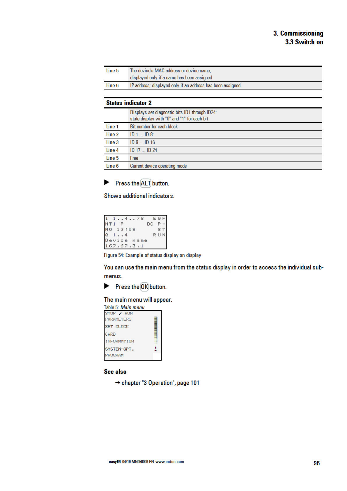
3.3.4 Status display on easyE4 control relays with display and keypad
After beingswitched on, the easyE4 base device willstart with thestatus display after
the boot logo.
Thestatus display has six lines, with eachone containing 16 characters.
Press the Altbutton toswitch betweendisplays.
Thefirst time you press ALT, the time will be replaced by the date.
Pressing the ALT buttonagain will switch to display 2
Row Status indicator 1 Status indicator 2
1
2
3
4
5
6
Figure 53: Start displays for easyE4 base device in English
Status indicator 1
Line 1 The Ethernet status for the base device without LED indicators will be shown for diagnostic purposes
I........ Inputs; the number will be shown during activity (1, 2, 3,..,8)
EOF The Ethernet port is not enabled;
no Ethernet cable connected; supply voltage off
The port is not enabled; the easyE4 device does not have an IP address
ECN Ethernet cable connected
EOK There is an Ethernet IP address, but the NET has not been configured
ENW NET data flow working; all NET stations working
ENM NET data flow working; one or more NET stations missing
EER Ethernet conflict or error, e.g.: duplicate IP address, address collision
Line 2 Settings in current program
RE Retention active
I Debounce active
NT NET stations with NET ID (1 this case)
DC Used to display the type of power used by the base device (AC or DC)
P P Buttons inactive (-) or active (+)
Line 3 Current device setting
WD Weekday
hh:mm Device time
1xALT DD-MM-YYY Displays the device date with the configured format
ST Configured startup behavior for the device;
nothing displayed – automatic starting is possible
94
Line 4
q Outputs; the number will be shown during activity (1, 2, 3, etc.)
RUN/STOP Current device operating mode
easyE4 04/19 MN050009 EN
Page 99
Page 100

 Loading...