

Page 1
VKP80 II
USER MANUAL
OEM
Command Reference: DOMC-0011e
Page 2

All rights reserved. Total or partial reproduction of this manual in whatever form, whether by printed or
electronic means, is forbidden. While guaranteeing that the information contained in it has been carefully
checked, CUSTOM ENGINEERING SPA and other entities utilized in the realization of this manual bear no
responsibility for how the manual is used.
Information regarding any errors found in it or suggestions on how it could be improved are appreciated.
Since products are subject to continuous check and improvement, CUSTOM ENGINEERING SPA reserves
the right to make changes in information contained in this manual without prior notifi cation.
Copyright © 2007 CUSTOM ENGINEERING S.p.a. – Italy
CUSTOM ENGINEERING SPA
Str. Berettine 2 - 43010 Fontevivo (PARMA) - Italy
Tel.: +39 0521-680111 - Fax: +39 0521-610701
http: www.custom.it
Customer Service Department:
Email: [email protected]
Page 3
PRINTER COMPONENTS
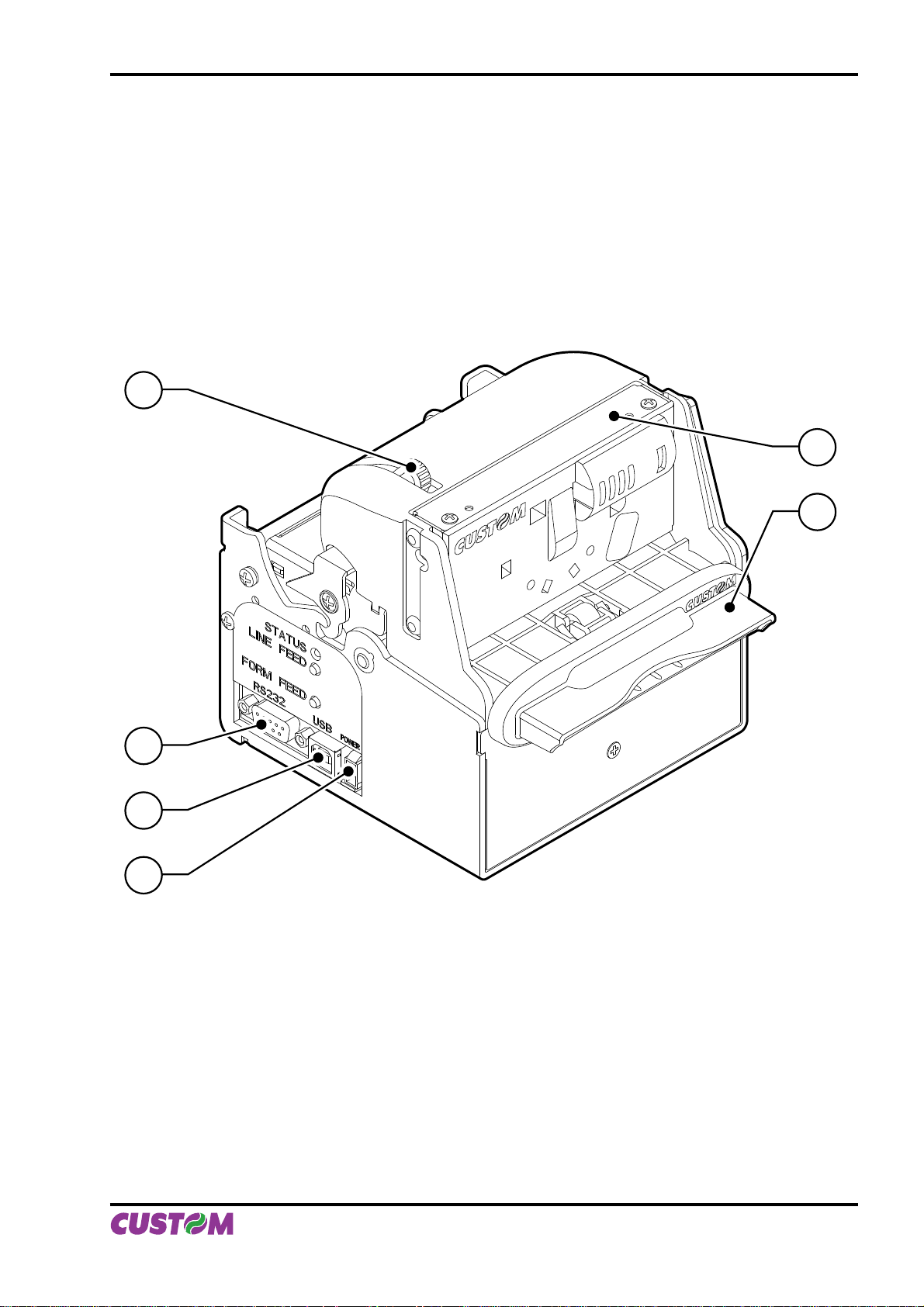
A. VKP80II - Front external view
1 - Opening lever
2 - Serial connector RS232
3 - USB connector
4 - Power supply connector
5 - Output paper mouth
6 - Cutter
1
6
5
2
3
4
User Manual VKP80II
Page 4
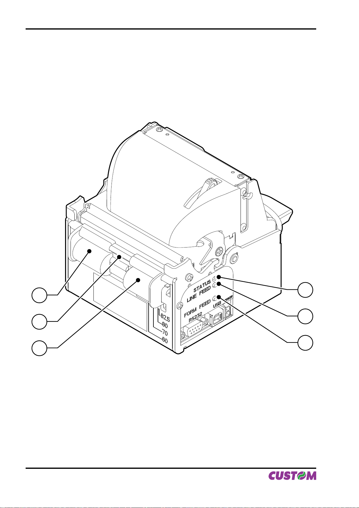
B. VKP80II – Rear external view
1 - Left paper mouth cursor
2 - Paper input
3 - Right paper mouth cursor
4 - Form Feed key
5 - Line Feed key
6 - Status led
1
2
3
6
5
4
VKP80II User Manual
Page 5

TABLE OF CONTENTS
INTRODUCTION
MANUAL CONTENTS ...................................................................................................................................... 1
EXPLANATORY NOTES USED IN THIS MANUAL .........................................................................................1
GENERAL SAFETY INFORMATION ................................................................................................................1
UNPACKING THE PRINTER ........................................................................................................................... 2
PRINTER FEATURES ......................................................................................................................................3
PRINTER DESCRIPTION ................................................................................................................................3
1. INSTALLATION AND USE
1.1 CONNECTIONS ......................................................................................................................................1-1
1.1.1 Power Supply ..................................................................................................................................1-1
1.2 SELF-TEST .............................................................................................................................................1-2
1.3 CONFIGURATION ...................................................................................................................................1-4
1.4 HEXADECIMAL DUMP ...........................................................................................................................1-4
1.5 MAINTENANCE ......................................................................................................................................1-5
1.5.1 Changing the paper roll ...................................................................................................................1-5
1.5.2 Ticket specifi cations ........................................................................................................................1-6
1.5.3 Adjusting paper width ......................................................................................................................1-6
1.5.4 Periodic cleaning .............................................................................................................................1-7
1.5.5 Notes for installation and use of printer with retracting .................................................................1-10
1.5.6 Notes for installation and lower fastening of printer ......................................................................1-11
2. INTERFACES
2.1 SERIAL INTERFACE ..............................................................................................................................2-1
2.2 USB INTERFACE ....................................................................................................................................2-3
3. TECHNICAL SPECIFICATIONS
3.1 TECHNICAL SPECIFICATIONS ..............................................................................................................3-1
3.2 DIMENSIONS ..........................................................................................................................................3-3
4. CHARACTER SETS
4.1 CHARACTER SETS ................................................................................................................................4-1
APPENDIX A - ACCESSORIES AND SPARE P ARTS
A.1 ACCESSORIES ..................................................................................................................................... A-1
A.1.1 Power Supply ................................................................................................................................. A-1
A.1.2 CD Full driver ................................................................................................................................ A-2
A.1.3 Adjustable paper holder support ................................................................................................... A-2
A.2 SUPPLIES.............................................................................................................................................. A-8
A.3 NOTES FOR TECHNICAL ASSISTANCE .............................................................................................. A-9
A.3.1 Replacing fuse ............................................................................................................................... A-9
User Manual VKP80II i
Page 6

TABLE OF CONTENTS
APPENDIX B - ALIGNMENT MANAGEMENT
B.1 TICKET ALIGNMENT ............................................................................................................................. B-1
B.1.1 Ticket alignment ............................................................................................................................. B-1
B.1.2 Enabling, calibrating and setting of parameters. ........................................................................... B-1
B.2 COMMANDS .......................................................................................................................................... B-3
B.2.1 Ticket Alignment. ............................................................................................................................ B-3
B.2.2 Setting the alignment distance. ...................................................................................................... B-3
B.2.3 Examples. ...................................................................................................................................... B-3
B.3 CHARACTERISTICS OF THE PAPER. ................................................................................................. B-6
B.3.1 Dimensions and position of the notch. ........................................................................................... B-6
B.3.2 Position of sensors ......................................................................................................................... B-8
B.3.3 Dimension of tickets ....................................................................................................................... B-9
B.4 METHODS OF USAGE ........................................................................................................................ B-10
B.4.1 Command sequences ................................................................................................................ B-10
B.4.1.1 Alignment at the cut .................................................................................................................. B-10
B.4.1.2 Alignment at printing ..................................................................................................................B-11
ii VKP80II User Manual
Page 7
INTRODUCTION
MANUAL CONTENTS
In addition to the Introduction which includes a description of the explanatory notes used in the manual, general
safety information, how to unpack the printer and a brief description of the printer including its basic features,
this manual is organized as follows:
Chapter 1: Contains the information required for correct printer installation and its proper use
Chapter 2: Contains information on interface specifi cations
Chapter 3: Contains Technical Specifi cations of the printer
Chapter 4: Contains the character sets (fonts) used by the printer
EXPLANATORY NOTES USED IN THIS MANUAL
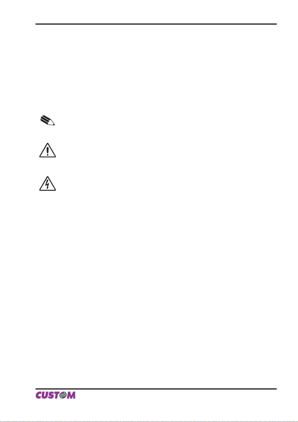
N.B.
Gives important information or suggestions relative to the use of the printer.
WARNING
Information marked with this symbol must be carefully followed to guard against damaging the
printer.
DANGER
Information marked with this symbol must be carefully followed to guard against operator injury
or damage.
GENERAL SAFETY INFORMATION
• Read and keep the instructions which follow.
• Follow all warnings and instructions indicated on the printer.
• Before cleaning the printer, disconnect the power supply.
• Clean the printer with a damp cloth. Do not use liquid or spray products.
• Do not operate the printer near water.
• Do not use the printer on unstable surfaces that might cause it to fall and be seriously damaged.
• During the integration of the printer, we strongly warn to keep an adeguate paper loop outlet underneath
the presenter, in order to allow the receipt being properly printed out.
• Only use the printer on hard surfaces and in environments that guarantee proper ventilation.
• Make sure the printer is placed in such a way as to avoid damage to its wiring.
• Use the type of electrical power supply indicated on the printer label. If in doubt, contact your retailer.
• Do not block the ventilation openings.
• Do not introduce foreign objects of any kind into the printer as this could cause a short circuit or damage
parts that could jeopardize printer functioning.
• Do not spill liquids onto the printer.
• Do not carry out technical operations on the printer, with the exception of the scheduled maintenance
procedures specifi cally indicated in the user manual.
• Disconnect the printer from the electricity supply and have it repaired by a specialized technician when:
A. The feed connector has been damaged.
B. Liquid has seeped inside the printer.
C. The printer has been exposed to rain or water.
D. The printer is not functioning normally despite the fact that all instructions in the users ma
nual have been followed.
E. The printer has been dropped and its outer casing damaged.
F. Printer performance is poor.
G. The printer is not functioning.
User Manual VKP80II 1
Page 8
INTRODUCTION
UNPACKING THE PRINTER
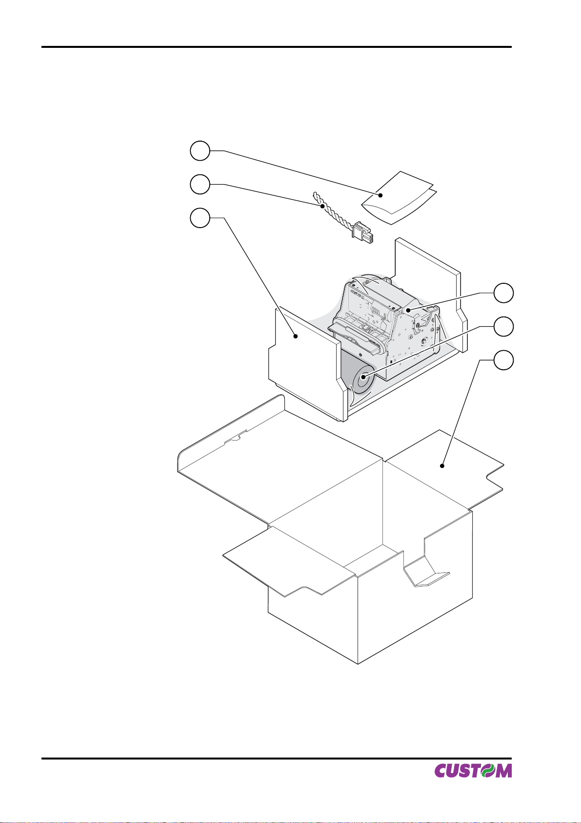
Remove the printer from its carton being careful not to damage the packing material so that it may be reused if the printer is to be transported in the future.
Make sure that all the components illustrated below are present and that there are no signs of damage. If
there are, contact Customer Service.
1
Installation instructions1.
Electrical supply cable2.
Foam packing shell3.
Box4.
Paper roll5.
Printer6.
2
3
6
5
4
Open the printer packaging•
Remove the paper roll•
Remove the manual (or CD-Rom)•
Remove the cable of power supply•
Take out the foam packing shell•
Take out the printer and remove it from its plastic covering.•
Keep the box, trays and packing materials in the event the printer must be transported/shipped in the •
future.
2 VKP80II User Manual
(Fig.1)
Page 9
INTRODUCTION
PRINTER FEATURES
VKP80II is the latest generation of ATMs, Kiosks and Ticket Printers with high printing speed 220mm/sec and
a very small footprint; it’s equipped with a 204 dpi (8 dots/mm) thermal printing mechanism.
In addition to normal printing functions, the printer offers a wide array of special features:
High speed printing:•
High Quality 80 mm/sec
Normal 180 mm/sec
High speed 220 mm/sec
Easy paper changing (automatic paper loading).•
Paper width 60/76/80/82.5mm, adjustable by the user.•
Bar code UPC-A. UPC-E, EAN13, EAN8, CODE39, ITF, CODABAR, CODE93, CODE128 and CODE32.•
3 standard and international character set fonts.•
Defi nition of function macros for automatic operation re-call.•
Graphic mode printing.•
Print density (-50% to +100%).•
Serial interfaces RS232: (from 1200 to 115200 bps)•
Interfaces: RS232-USB•
High reliability autocutter.•
Illuminated paper mouth.•
Paper pre-tensioner system for high capability paper roll.•
Double function ticket presentation: “ejecting” and “retracting”.•
Sensors: paper end, ticket present, black mark, head temperature, opening of printing unit (near paper •
end on roll support is optional).
PRINTER DESCRIPTION
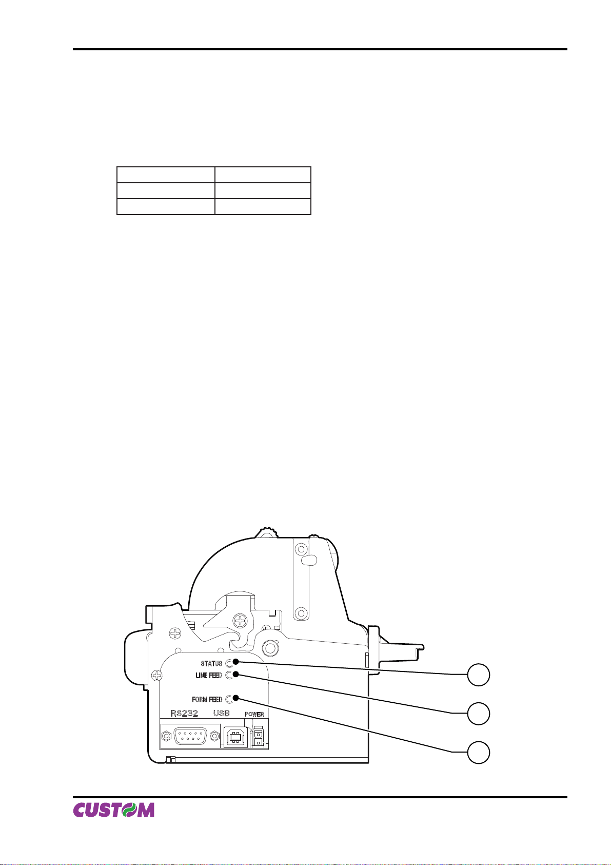
The printer (fi g.2) is comprised of a metal frame, printing mechanism, a cutter and an ejector.
Located on the keypad are the following keys: FORM FEED (1), LINE FEED (2) and status LED (3).
3
2
(Fig.2)
1
User Manual VKP80II 3
Page 10
INTRODUCTION
• LINE FEED key: When the LINE FEED key is pressed, the printer advances the paper so that the paper
may be inserted in the printing mechanism. During power-up, if the LINE FEED key
is held down, the printer enters the SETUP routine.
• FORM FEED key: When the FORM FEED key is pressed, the printer advances the paper by a pre-set
length. During power-up, if the FORM FEED key is held down, the printer will perform
the FONT TEST routine.
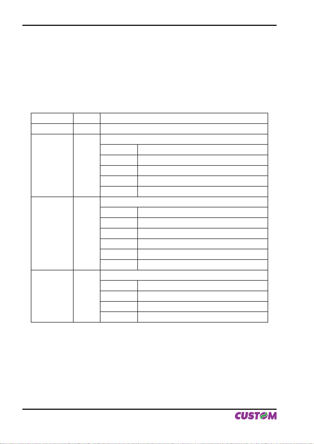
• STATUS LED: displays printer hardware status. In case of malfunction, the colour and fl ash frequency
changing as follows:
STATUS LED COLOR DESCRIPTION
Turned on Green Printer on: no error
Communication status
Nr. Flashings Description
Flashing Green
Flashing Yellow
Flashing Red
1 Receive data
2 Reception errors (parity, frame error, overrun error)
3 Misinterpret command
4 Command reception time out
Recovering error
Nr. Flashings Description
2 Heading over temperature
3 Paper end
4 Paper jam
5 Power supply voltage incorrect
6 Cover opened
Unrecovering error
Nr. Flashings Description
3 RAM error
4 EEPROM error
4 VKP80II User Manual
5 Cutter error
(Tab.1)
Page 11
1. INSTALLATION AND USE
1.1 CONNECTIONS
1.1.1 Power Supply
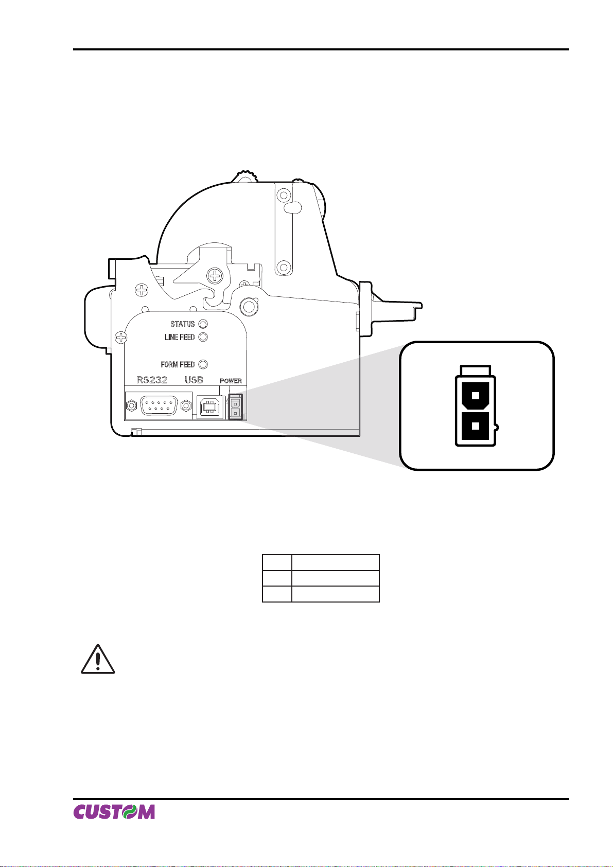
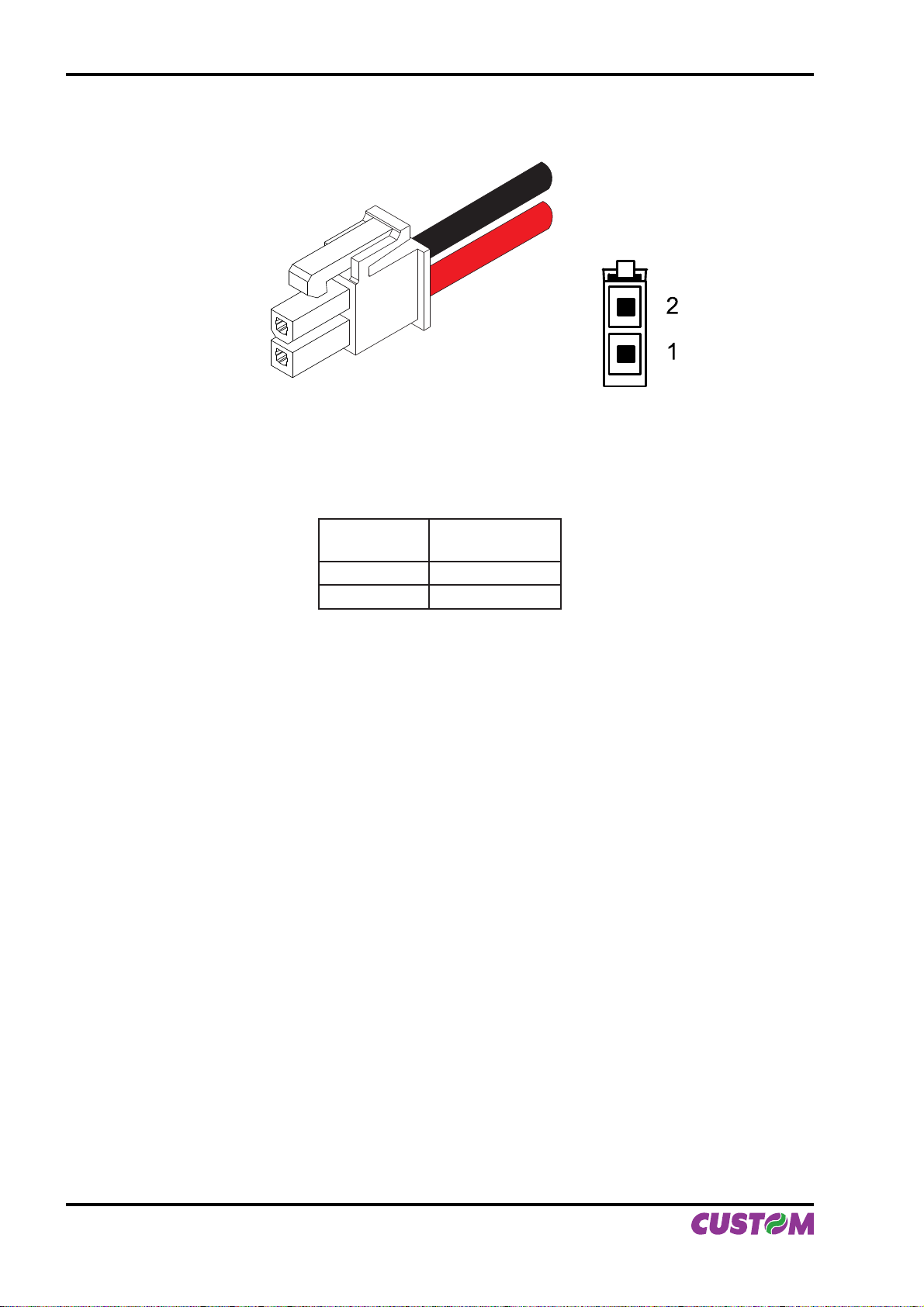
The printer is equipped with a 2 pin male molex connector series 5569 (Vertical), for the power supply (see
Fig. 1.1). The connector pin confi guration is as follows :
(Fig.1.1)
Model no. type: Header : 90° Molex series 5569 (no. 39-30-1020)
Housing: Molex series 5557 (no. 39-01-3022)
PIN SIGNAL
1 +24 V
2 GND
WARNING:
Respect power supply polarity.
(Tab.1.1)
2
1
User Manual VKP80II 1-1
Page 12
1. INSTALLATION AND USE
This picture shows the power supply cable included in the printer packaging :
(Fig.1.2)
MOLEX FEMALE
CONNETTOR 2 PIN
The connector pin confi guration of this cable is as follows:
Female
connector
Pin 1 RED
Pin 2 BLACK
Note : The red cable is for +24 Vdc.
The black cable is for signal ground.
1.2 SELF-TEST
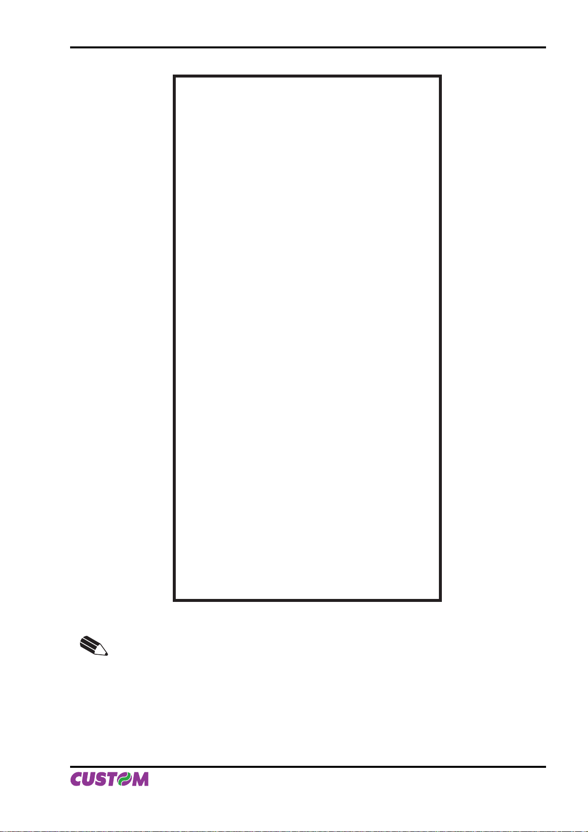
Printer operating status is indicated in the confi guration print-out in which, next to the name of the compo-
nents displayed (see fi gure 1.3), the following information is given:
Cable color
OPPOSITE VIEW SIDE
OF CABLE INSERTION
(Tab.1.2)
Under INTERFACE is given the interface present (RS232).•
Under PROGRAM MEMORY TEST, DYNAMIC RAM TEST, EEPROM TEST and CUTTER TEST, the •
message OK appears if functioning and NOT OK if faulty.
Under HEAD VOLTAGE is given the voltage of the head.•
Under HEAD TEMPERATURE is given the temperature of the head. •
Under PAPER PRINTED is given the number of centimetres of paper printed. •
Under CUT COUNTER is given the number of cuts made. •
Under RETRACT COUNTER is given the number of retract made. •
Under POWER ON COUNTER is given the number of power-ups made.•
1-2 VKP80II User Manual
Page 13
1. INSTALLATION AND USE
PRINTER SETUP
INTERFACE...................................RS232
PROGRAM MEMORY TEST..........OK
DYNAMIC RAM TEST....................OK
EEPROM TEST..............................OK
CUTTER TEST...............................OK
HEAD VOLTAGE [V] = 23,37
HEAD TEMPERA TURE [°C] = 25
PAPER PRINTED [cm] = 40
CUT COUNTER = 1
RETRAC COUNTER = 0
POWER ON COUNTER = 4
RS232 Baud Rate .....................: 19200 bps
RS232 Data Length...................: 8 bits/chr
RS232 Parity.............................: None
RS232 Handshaking .................: Xon/Xoff
Busy Condition ..........................: RcFull
USB Address Number
USB Status Monitor
Autofeed....................................: CR Disabled
Print Mode.................................: Normal
Chars / inch ...............................: A=15 B=20 cpi
Speed / Quality..........................: Normal
Paper Retracting .......................: Disabled
Notch Alignment ........................: Disabled
Notch Threshold
Notch Distance [mm]
Current ......................................: Normal
Print Density..............................: 0%
(1)
............: 0
(2)
...............: Disabled
(3)
.....................: 2.0V
(3)
..............: 00
[FF] key to enter setup
[LF] key to skip setup
(Fig.1.3)
NOTE:
(1)
This parameter is displayed if the printer has an USB interface; it’s used to identify
univocally the USB printer by a numerical address code, if on the PC are connected
two printers that are the same models for example two VKP80-UE.
(2)
This parameter is displayed if the printer has an USB interface. The Status Monitor
is an additional printing driver component that allows the printer status monitoring. It
must be enabled only if it was installed the Status Monitor specifi c driver.
(3)
If the “Notch Alignment” parameter is “Disabled” this parameter doesn’t appear in the
“Printer Setup” ticket.
User Manual VKP80II 1-3
Page 14

1. INSTALLATION AND USE
1.3 CONFIGURATION
This printer permits the confi guration of default parameters. The printer’s confi gurable parameters are:
D
RS232 Baud Rate: 115200, 57600, 38400, 19200
RS232 Data length: 7, 8
RS232 Parity: None
RS232 Handshaking: XON/XOFF
Busy condition: RxFullD , OffLine/RxFull
USB Address Number: 0
USB Status Monitor: Disabled
Autofeed: CR disabled
Print mode: Normal
D
bits/char.
D
, Even, Odd.
D
, 1, 2, 3, 4, 5, 6, 7, 8, 9.
D
, CR enabled.
D
, Reverse.
D
, Hardware.
D
, Enabled.
(4)
.
Characters per inch: A=11 B=15 cpi, A=15 B=20 cpi
Speed/Quality: High Quality, Normal
Paper retract
(5)
: Disabled
Notch Alignment: Disabled
D
, Enabled.
D
, Enabled.
Notch Threshold: 0.5, 1.0, 1.5, 2.0
Notch Distance [mm]
Current: Low, High, Normal
(6)
: From 00
D
.
D
, High Speed.
D
, 2.5, 3.0, 3.5, 4.0, 4.5.
D
to 32 mm.
Print density: -50%, -37%, -25%, -12%, 0%
, 9600, 4800, 2400,1200.
D,
A=20 B=15 cpi.
D
, +12%, +25%, +37%, +50%.
Please note: the parameters marked with the symbol D represent the default values.
(4)
NOTE:
This parameter is valid only wth serial interface; using this parameter, it is possible to select
whether the Busy signal is activated when the printer is both in Off Line status and the buffer
is full, or only if the reception buffer is full.
(5)
If, at power-up, paper is present on the ejector and if this parameter has been activated, the
printer will retract the paper. Otherwise, if the parameter is deactivated, the printer will eject
the paper.
(6)
During the setup phase it’s possible to set the notch distance using a values range from 0 to
39 mm. The maximum distance accepted is 32 mm, so even if values from 33 to 39 mm are
inserted, the distance remains 32 mm.
The settings made are stored in EEPROM (nonvolatile memory).
During power-up, if the LINE FEED key is held down, the printer enters the autotest routine and prints out the
setup report. The printer will remain in standby in Hexadecimal dump mode (see section 1.5) until another
key is pressed or characters are received through the printer communication port. When the FORM FEED
key is pressed, the printer enters parameter confi guration. When the LINE FEED key is pressed, the printer
exits setup and terminates the Hexadecimal dump function. When the receive buffer is full, if handshaking is
set to XON/XOFF, the printer sends the XOFF ($13) on the serial port. When the receive buffer has cleared
once again, if handshaking is set to XON/XOFF, the printer sends the XON ($11) on the serial port.
1.4 Hexadecimal dump
This function is used to display the characters received from the communications port; the printer prints out
both the hexadecimal code received as well as the corresponding ASCII code.
Once the autotest routine has fi nished, the printer enters Hexadecimal Dump mode. The printer remains in
standby until a key is pressed or characters are received from the communications port; for every 24 characters received it prints hexadecimal values and ASCII codes (if the characters appear underlined, it means the
receive buffer is full). Shown below is an example of a Hexadecimal Dump :
HEXADECIMAL DUMP ASCII DUMP
0x000000 48 65 78 61 64 65 63 69 6D 61 6C 20 64 75 6D 70 20 66 75 6E 63 74 69 6F Hexadecimal dump functio
0x000018 6E 20 30 31 32 33 34 35 36 37 38 39 20 61 62 63 64 65 66 67 68 69 6A 6B n 0123456789 abcdefghijk
0x000030 6C 6D 6E 6F 70 71 72 73 74 75 76 77 78 79 7A 2E lmnopqrstuvwxyz.
1-4 VKP80II User Manual
Page 15
1. INSTALLATION AND USE
1.5 MAINTENANCE
1.5.1 Changing the paper roll
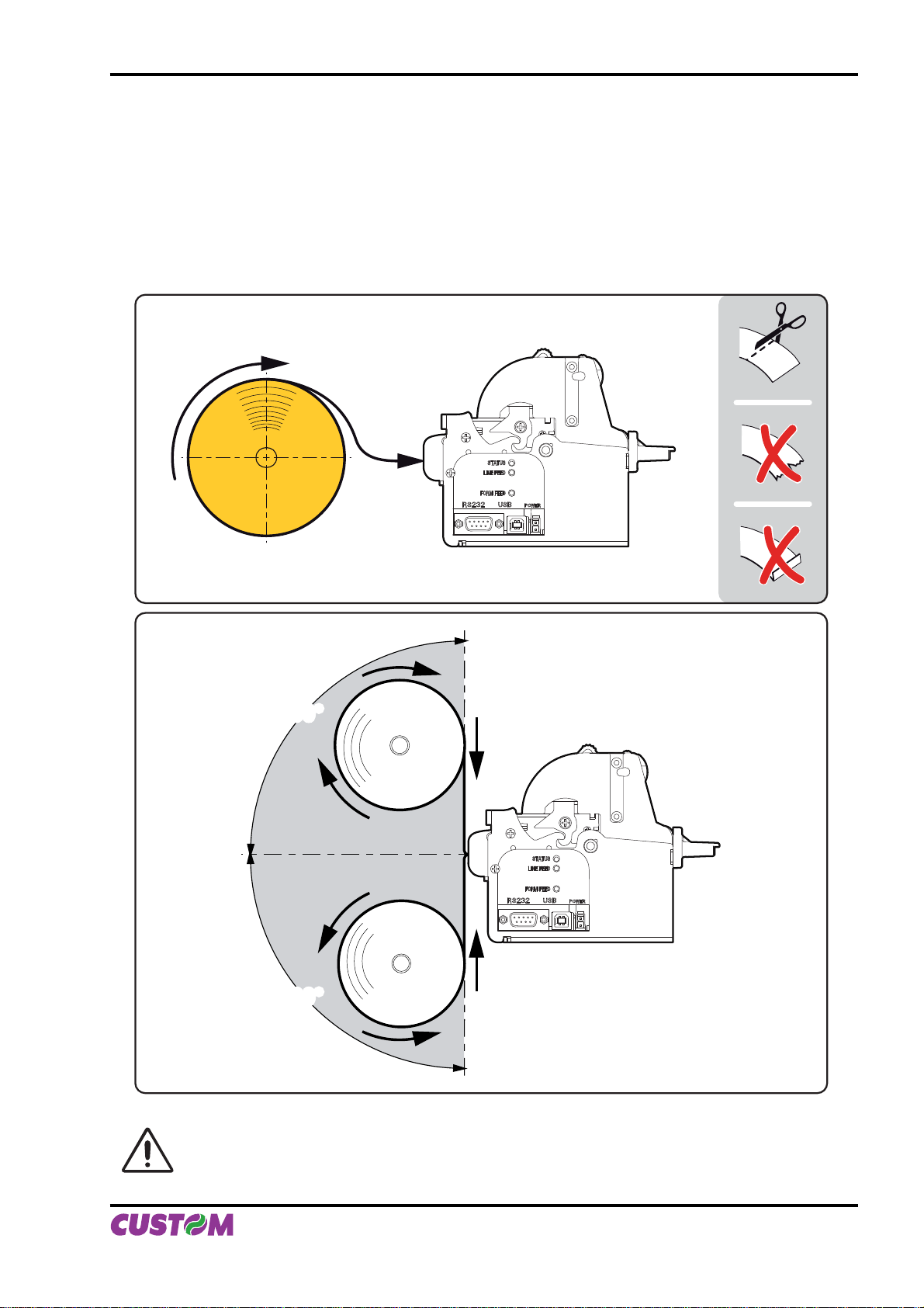
To change the roll of paper, proceed as follows:
Position the paper roll so that it unrolls in the direction shown in fi g.1.4.1.
Insert the paper into the paper infeed opening and wait for it to load automatically (see fi g.1.4).2.
Fig.1.6 gives alignment specifi cations for correct paper loading if no roll holder support is present.
(Fig.1.4)
90°90°
OK
OK
90°
90°
(Fig.1.5)
WARNING
Before inserting the paper, make sure the cut is straight (see fi g.1.4).
User Manual VKP80II 1-5
Page 16
1. INSTALLATION AND USE
1.5.2 Ticket specifi cations
Paper with alignment notches may be used; referred to Appendix B on this manual to see the ticket specifi ca-
tions and management of notch alignment.
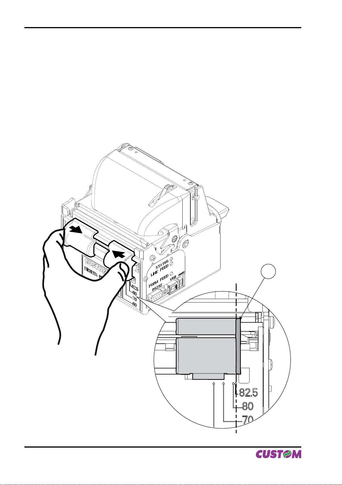
1.5.3 Adjusting paper width
Paper width may be adjusted from 60mm to 82.5mm using the right (Dx) and Left (Sx) slides located at the
paper infeed opening.
Move the right and left slides to adjust the paper width (see fi g.1.6).
Below the right slide there are four point of reference for paper width (60, 70, 80 and 82.5mm).
Move the slides to align the internal side of the fi n (A) with the point of reference.
(Fig.1.6)
A
1-6 VKP80II User Manual
Page 17
1. INSTALLATION AND USE
1.5.4 Periodic cleaning
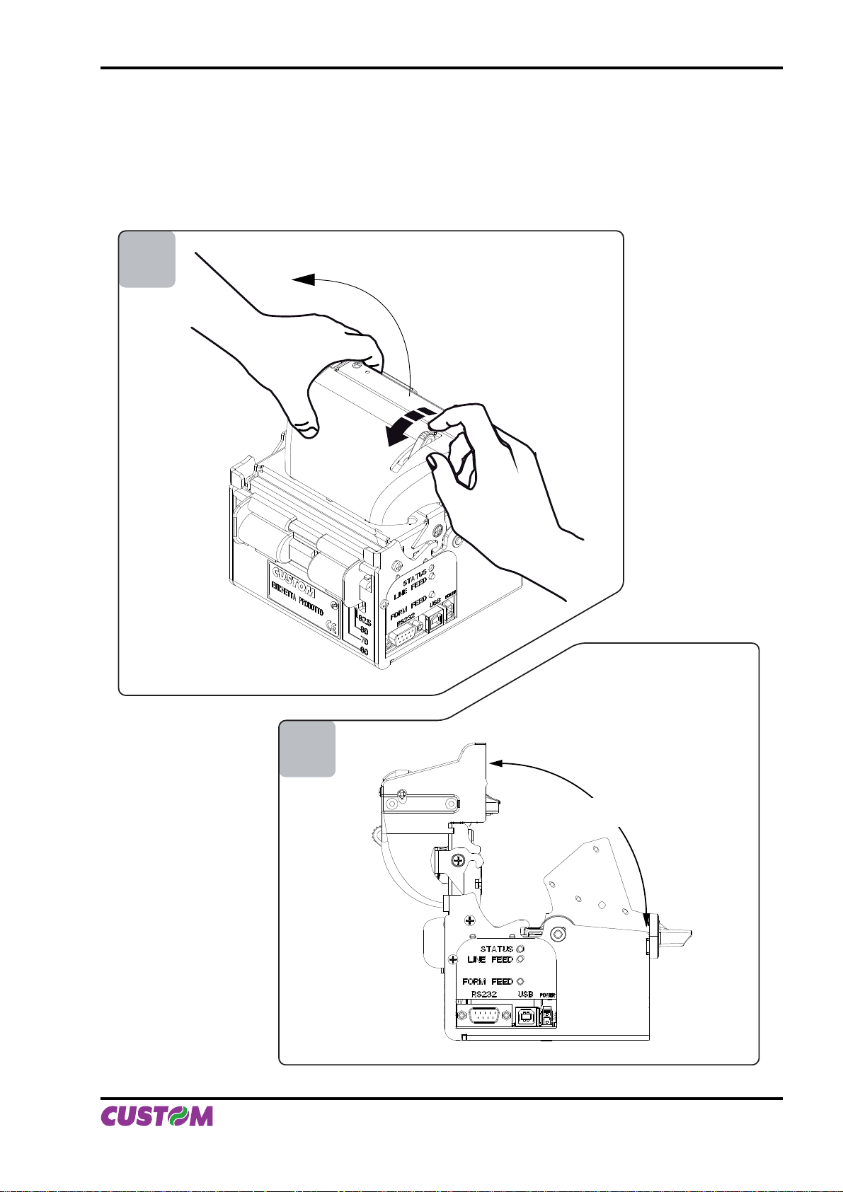
The printer inside needs a periodic cleaning. Check the inside of the printer
While pushing the opening lever down, lift the head/cutter unit (see fi g.1.7 and fi g.1.8) until it locks into posi-
tion.
1
(Fig.1.7)
2
90° max
(Fig.1.8)
User Manual VKP80II 1-7
Page 18
1. INSTALLATION AND USE
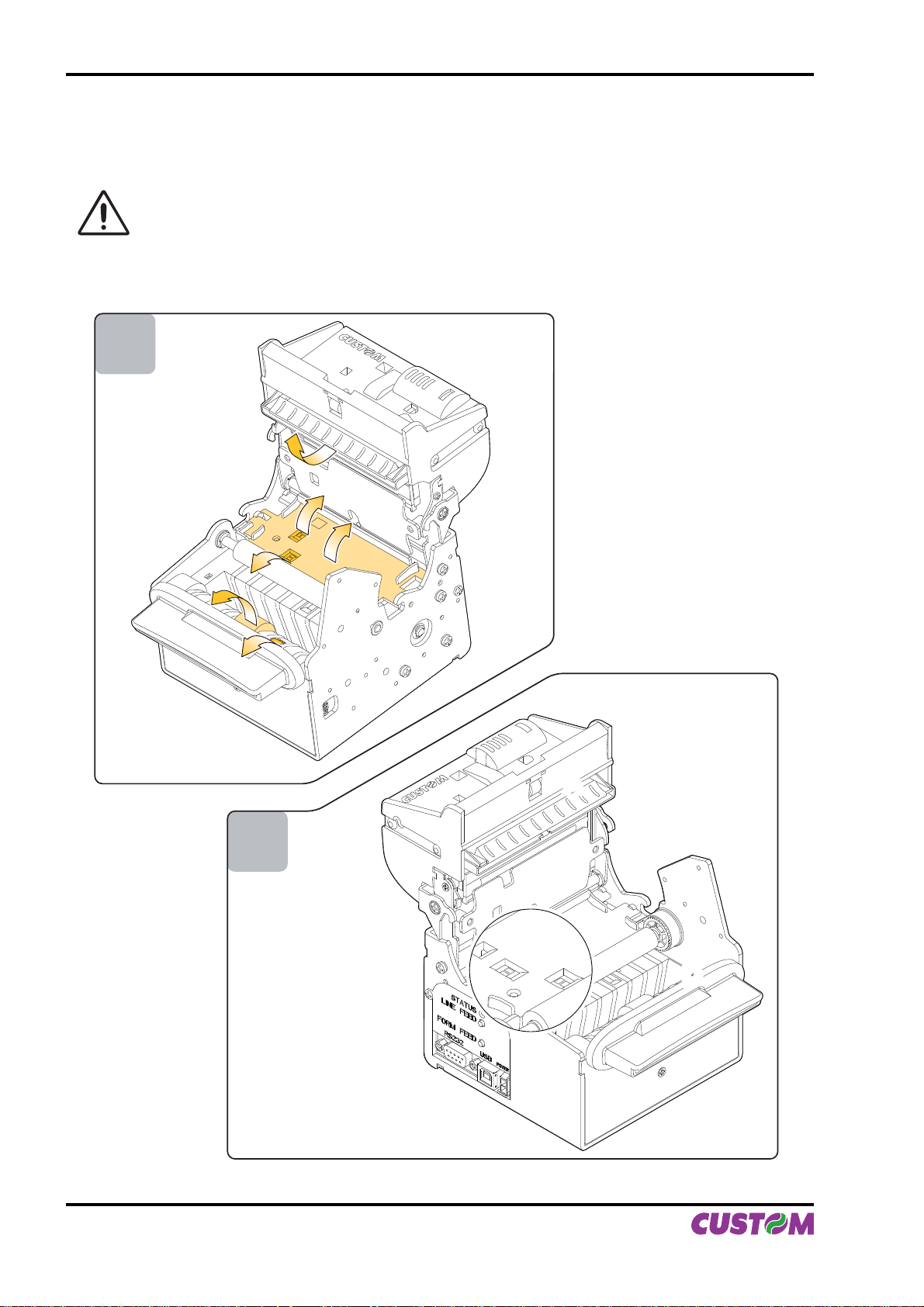
Check that there are no scraps of paper at the points indicated in fi g.1.9 on the paper infeed and outfeed
openings, on the cutter opening or the ejector roller. If there are, remove the scraps before proceeding with
any other operation.
WARNING
Periodically remove accumulated paper dust from the upper plastic slide (A) and the area
around the paper outfeed sensor (D). Clean carefully the paper sensor (B) and the notch sensor
(C). To clean, do not use harsh chemical solvents; the use of a soft, alcohol-moistened cloth and
pneumatics air is recommended (see fi g.1.10)
3
(Fig.1.9)
4
(Fig.1.10)
B
B
AA
C
C
D
D
1-8 VKP80II User Manual
Page 19
1. INSTALLATION AND USE
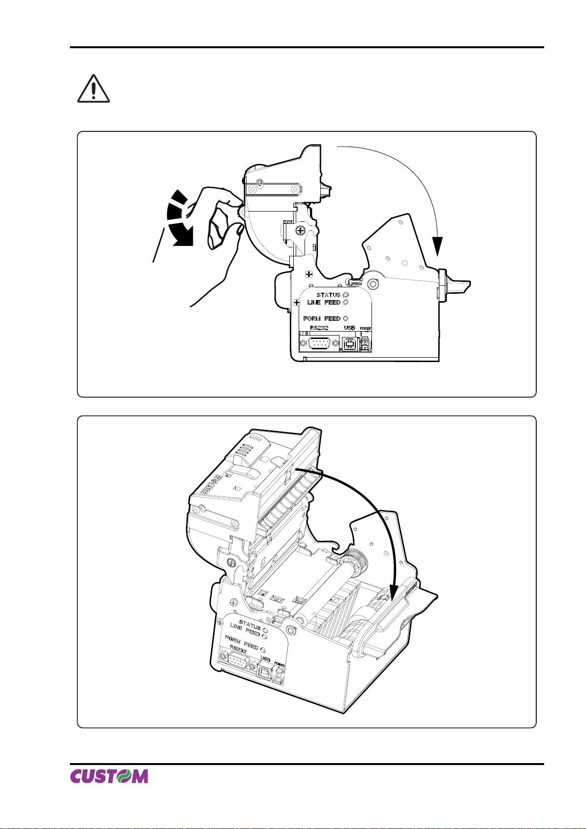
WARNING
To close the head/cutter unit:
1) push the opening lever down (see fi g.1.11);
2) lower the head/ cutter unit and press hard in the position shown in fi g.1.12.
(Fig.1.11)
(Fig.1.12)
User Manual VKP80II 1-9
Page 20
1. INSTALLATION AND USE
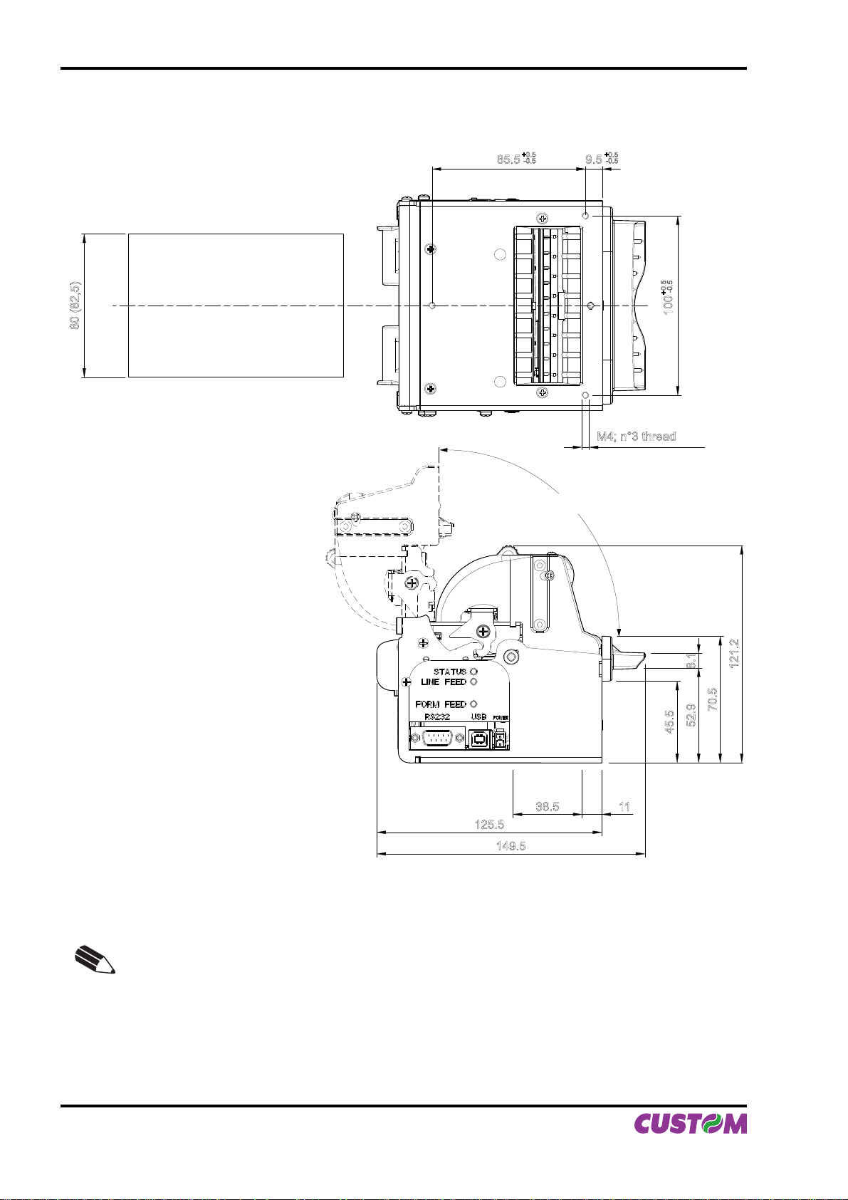
1.5.5 Notes for installation and use of printer with retracting
80 (82,5)
85.5
+0.5
-0.5
90° max
+0.5
-0.5
9.5
M4; n°3 thread
+0.5
-0.5
100
70.5
52.9 8.1
45.5
38.5 11
125.5
149.5
(Fig.1.13)
N.B.: “Ejector outfeed”: When assembling the printer on the machine, be sure to leave adequate space for the paper loop below. If this is not done, the ticket could crease at the cutting
area, causing the ticket to jam in the paper outfeed opening.
121.2
1-10 VKP80II User Manual
Page 21
1. INSTALLATION AND USE
In the following table are reported the length recommended for the tickets using of the retracting function:
TICKET LENGTH TICKET PRESENTATION (MAX)
70 mm 10 mm
80 mm 10mm ÷ 30mm
80mm ÷ 220mm 10mm ÷ 30mm
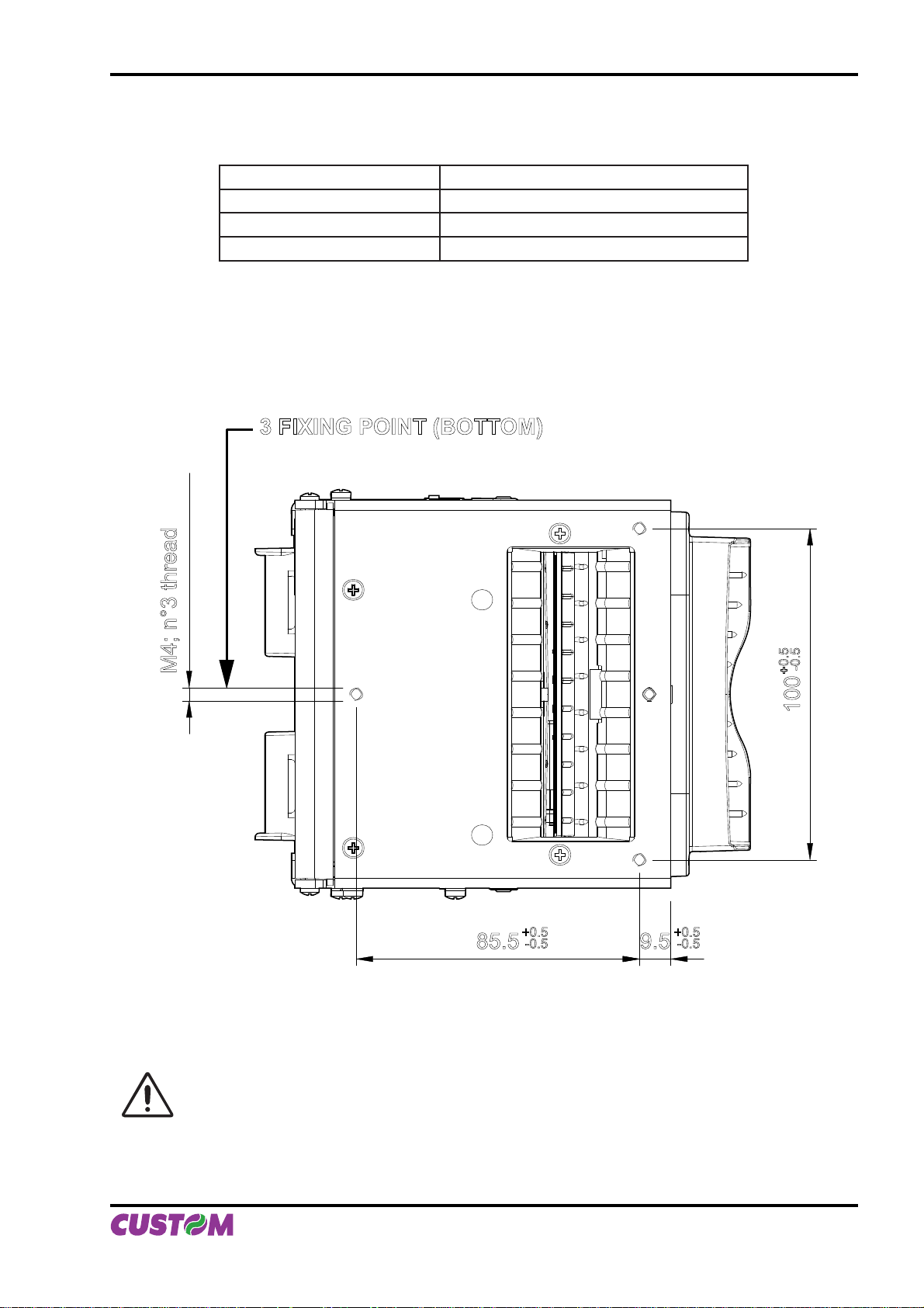
1.5.6 Notes for installation and lower fastening of printer
3 FIXING POINT (BOTTOM)
M4; n°3 thread
+0.5
85.5
ATTENTION
It’s very important to consider the screws length to not damage the internal sensor board near
the lower fi xing holes (see fi g. 1.15).
-0.5
9.5
+0.5
-0.5
+0.5
(Fig.1.14)
-0.5
100
User Manual VKP80II 1-11
Page 22
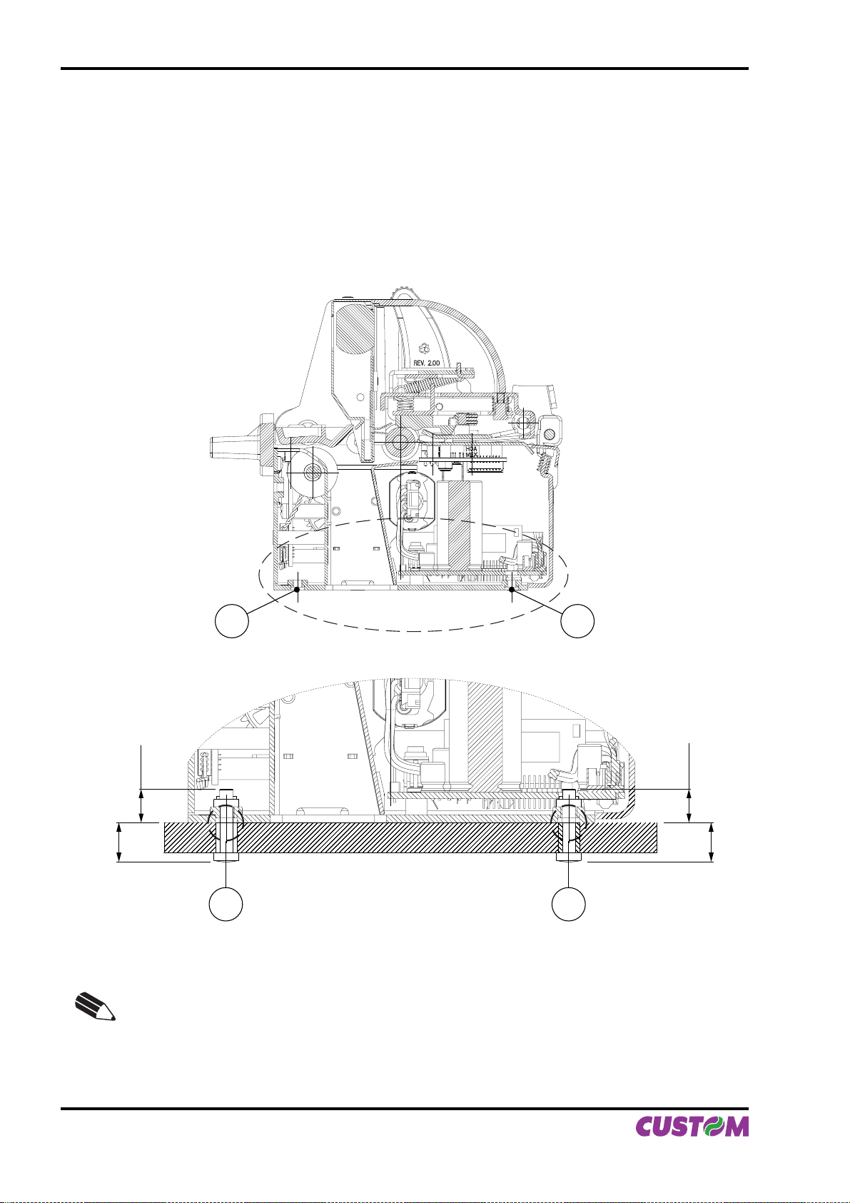
1. INSTALLATION AND USE
On the basis of panel thickness calculate the screws length as follows :
Lv ≤ Pn + Sp
where
Lv : indicates screw length
Pn : 8 mm
Sp : panel thickness
For example if panel thickness is 10mm ( Sp = 10mm ) the max screw length will be 18mm.
1
8 mm
Sp
2
1 2
(Fig.1.15)
N.B.: The reference (1) indicates the screws that must located in the two external holes in front
of the printer; the reference (2) indicates the screw that must located in the center hole of the
rear side of the printer.
8 mm
Sp
1-12 VKP80II User Manual
Page 23
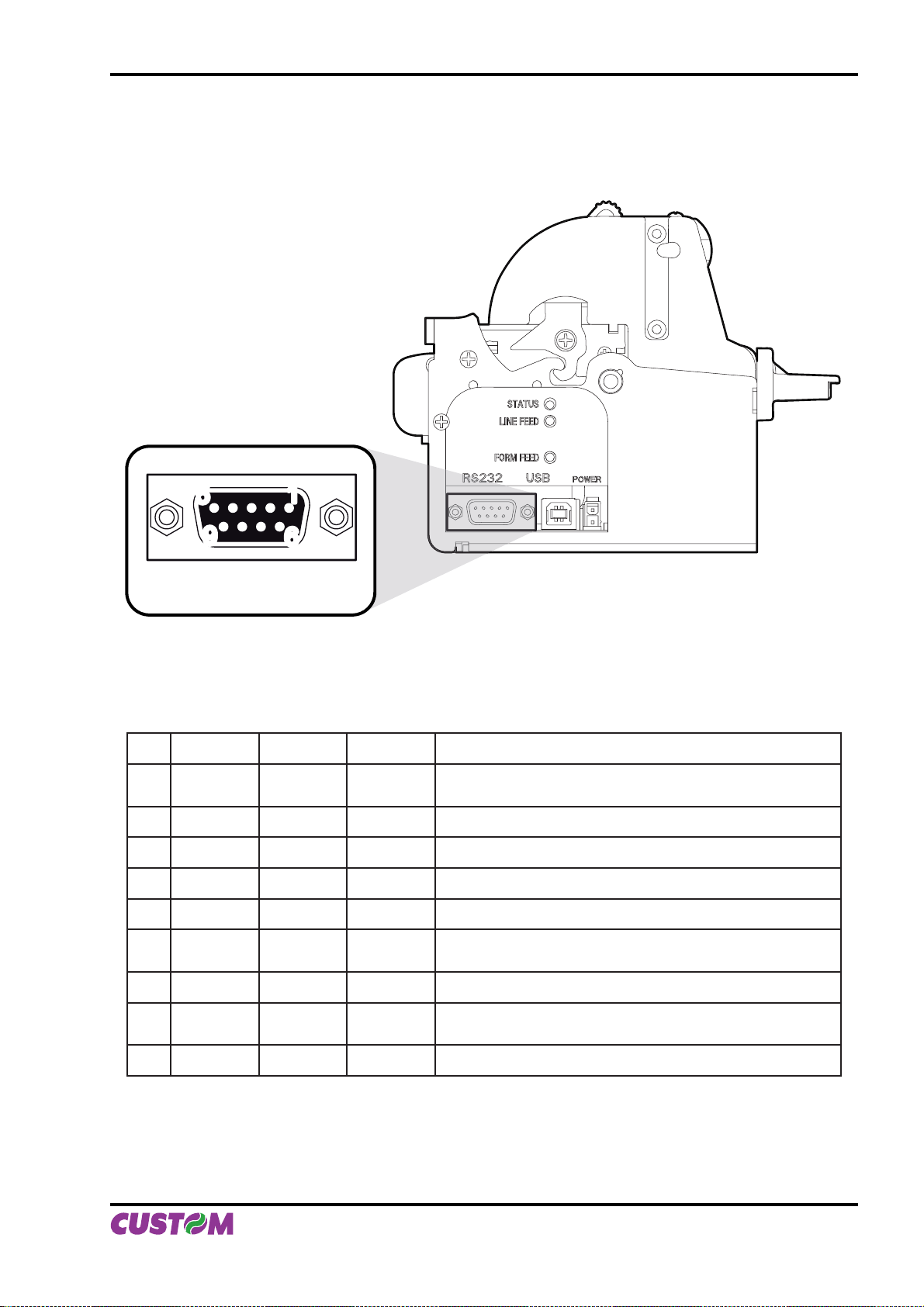
2.1 SERIAL INTERFACE
The printer has an RS232 interface with 9-pin female connector.
2. INTERFACES
5
9
1
6
RS232
Refer to the table below for the connector pin signals:
PIN SIGNAL IN/OUT HOST DESCRIPTION
1 DCD OUT DCD
2 TXD OUT RXD Transmit data. Serial output (from the host)
3 RXD IN TXD Receive data. Serial data input (to the host)
4 N.C. - N.C. Not connected
5 GND - GND Signal Ground
6 DTR OUT DSR
Printer on and operational (active with RS232 level high)
Printer on (active with RS232 level high)
Individuation Data Carrier.
Ready to send.
(Fig.2.1)
(Tab.2.1)
7 N.C. - N.C. Not connected
8 RTS OUT CTS
9 N.C. - N.C. Not connected
Ready to receive data (active with RS232 level high)
Ready to send.
User Manual VKP80II 2-1
Page 24
2. INTERFACES
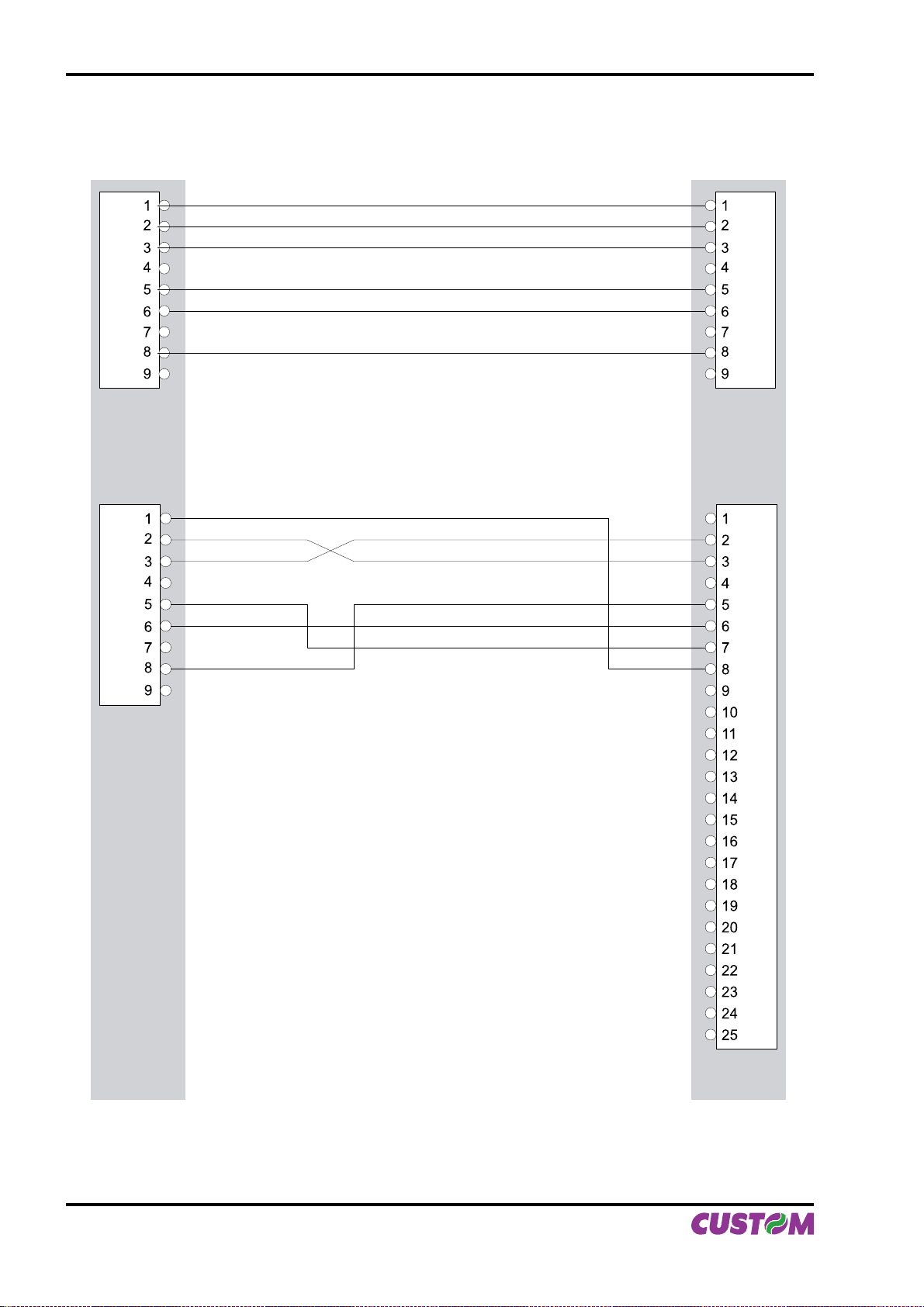
The diagrams below illustrate a sample connection between the printer and PC using a 25- or 9-pin female
connector.
(Fig.2.2)
VKP80II PC
2-2 VKP80II User Manual
Page 25
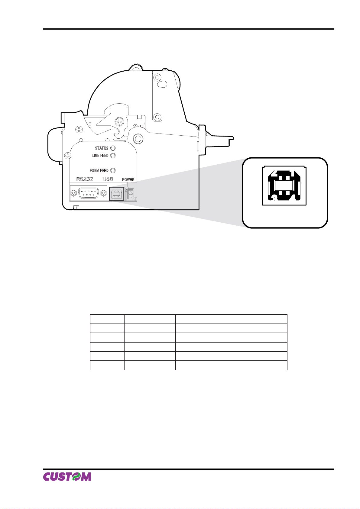
2.2 USB INTERFACE
2. INTERFACES
1122
4433
(Fig.2.3)
Printers with USB serial interface conform to USB 1.1 standards and have the following specifi cations:
Communication speed 12 Mbit/sec•
“Receptacle series B” - type connector.•
Refer to the table below for the connector pin signals and connection to a device:
PIN SIGNAL DESCRIPTION
1 VBUS N.C.
2 D- Data -
3 D+ Data +
4 GND Ground signal
Shell Shield Cable shield
USB type B
(Tab.2.2)
User Manual VKP80II 2-3
Page 26

2. INTERFACES
Blank page
2-4 VKP80II User Manual
Page 27
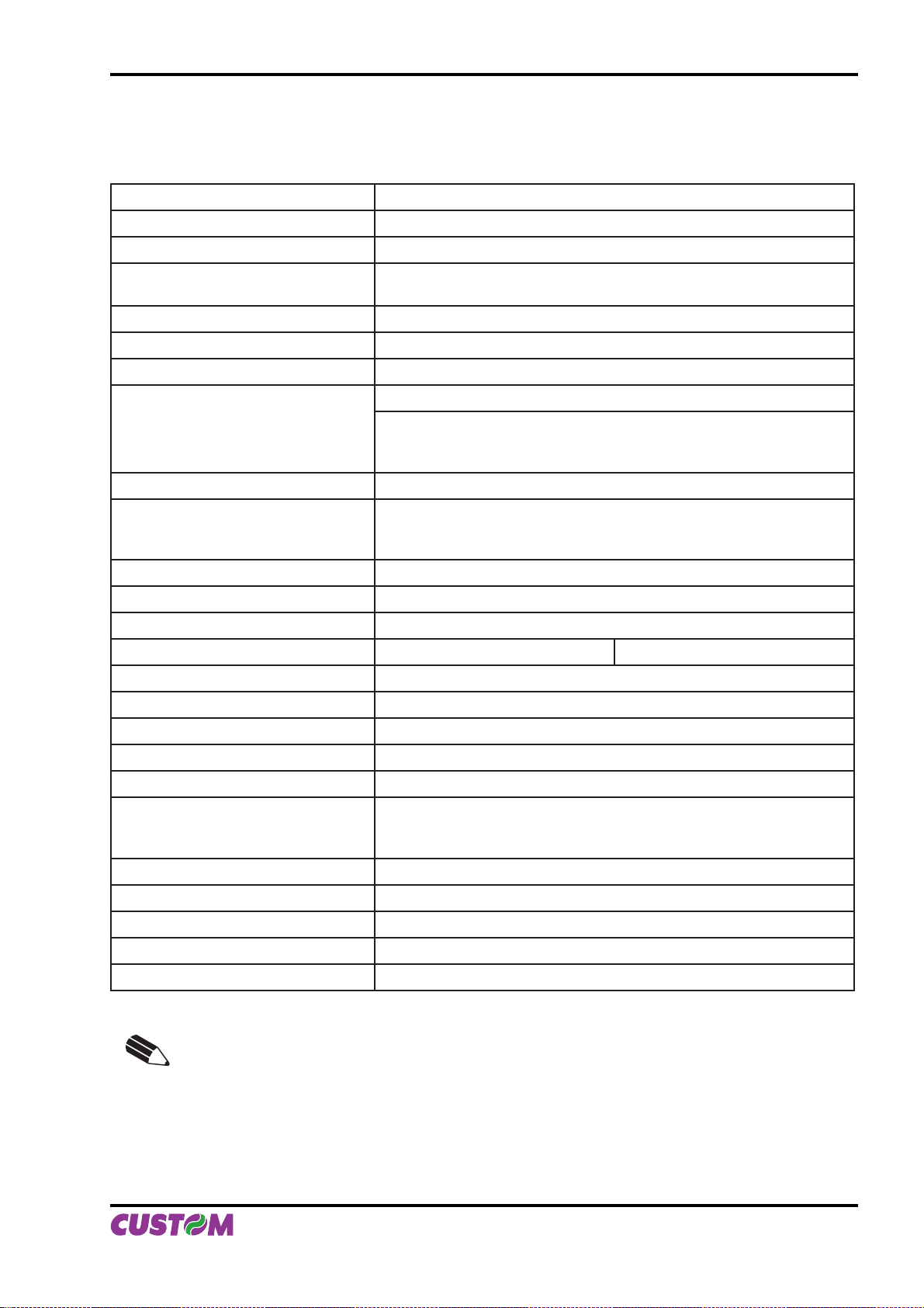
3. TECHNICAL SPECIFICATIONS
3.1 TECHNICAL SPECIFICATIONS
Table 3.1 gives the main technical specifi cations for the 204 dpi printer model.
(Tab.3.1)
Print method Thermal, fi xed head (8 dot/mm)
Resolution 204 DPI (8 dot/mm)
Paper specifi cations
Type of paper Thermal rolls
Heat-sensitive side on outside of roll
Recommended types of paper from 55 g/m2 to 110
Width from 60
Internal roll core diameter 25mm
max Ø180 mm
External roll diameter
OPTIONAL
Upper attachment
OPTIONAL
OPTIONAL
Lower attachment
Core type Cardboard or plastic
Sensors Head temperature, black mark, paper presence, ticket presence on
output, opening of printing unit, (near paper end on roll support is
Printing mode Straight, 90°, 180°, 270°
(1)
g/m2 (KANZAN)
(2)
to 82,5 mm
(3) (4)
Rear attachment
optional)
max Ø170 mm
max Ø180 mm
max Ø180 mm
(5)
(5)
(5)
Printing format Height / Width from 1 to 8, bold, reverse, underlined, italic
Character fonts PC437, PC850, PC860, PC863, PC865, PC858.
Available interfaces RS232 USB
Baud rate From 1200 to 115200 bps
Receive buffer 16 Kbytes
Flash memory 384 Kbytes
Graphics memory 2 logos of 608 x 862 dots (for 80/82,5mm paper width)
Printing Driver Windows
Length [mm] =
Dimensions
(5)
Height [mm] =
Width [mm] =
Weight
(5)
TM
95, 98, ME, NT4, 2K, XP, Linux
115
115
115
2117 gr.
Printing speed
High quality 90 mm/sec
Normal 120 mm/sec
High speed 140 mm/sec
NOTE:
(1)
For paper from 90 to 110 g/m2 enable the dispenser continuous mode:
$1D $65 n [m]
(2)
For ticket width = 60 mm do not exceed a max length of 250 mm.
(3)
Referred to model without paper holder support.
(4)
It’s better to use an external shock absorber for rolls with a diameter higher than or
equal to 100 mm.
(5)
Referred to model without paper holder support.
User Manual VKP80II 3-1
Page 28
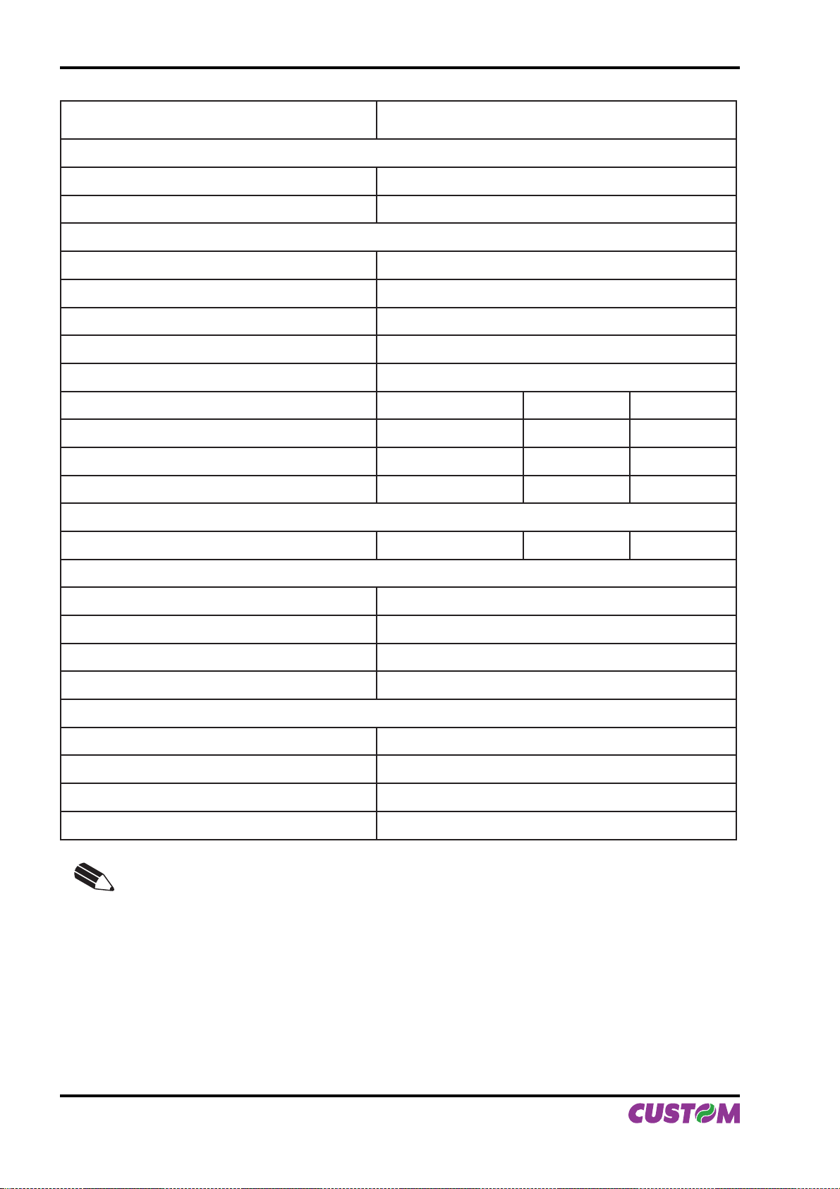
3. TECHNICAL SPECIFICATIONS
Power supply 24 Vdc ± 10%
(optional external power supply)
Absorption (current setting = Normal)
Stand-by 0,1 A
Medium (50% dot ON) 2,2 A
Environmental conditions
Operating temperature 0°C - 50°C
Relative humidity 10% - 80% w/o condensation
Storage temperature / Humidity -20°C - 70°C / 10% - 90%
OPTIONS Roll holder support
Emulation ESC/POS
Character density 11 cpi 15 cpi 20 cpi
Number of columns 88 123 160
Chars / sec 1760 2460 3200
TM
Lines / sec 20 20 20
Characters
Normal 2,25x3 1,625 x 3 1,25 x 3
Retracting function
Ticket length Ticket presentation
70 mm 10 mm
80 mm 10 mm - 30 mm
80 mm - 220 mm 10 mm - 30 mm
Ejecting function
Ticket length Ticket presentation
70 mm 10 mm
> 80 mm 10 mm - 30 mm
(6)
10 mm - 30 mm
NOTE:
350 mm
(6)
Maximum length recommended to guarantee the printer effi ciency.
3-2 VKP80II User Manual
Page 29
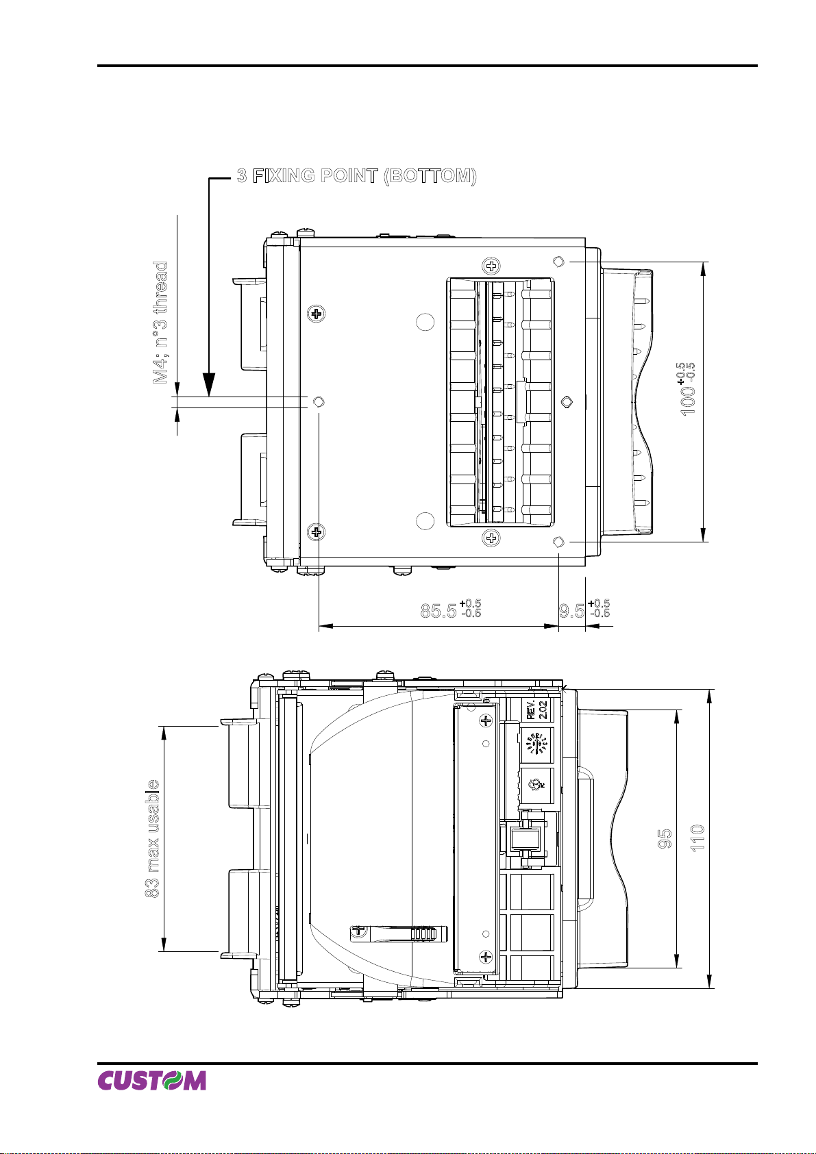
3.2 DIMENSIONS
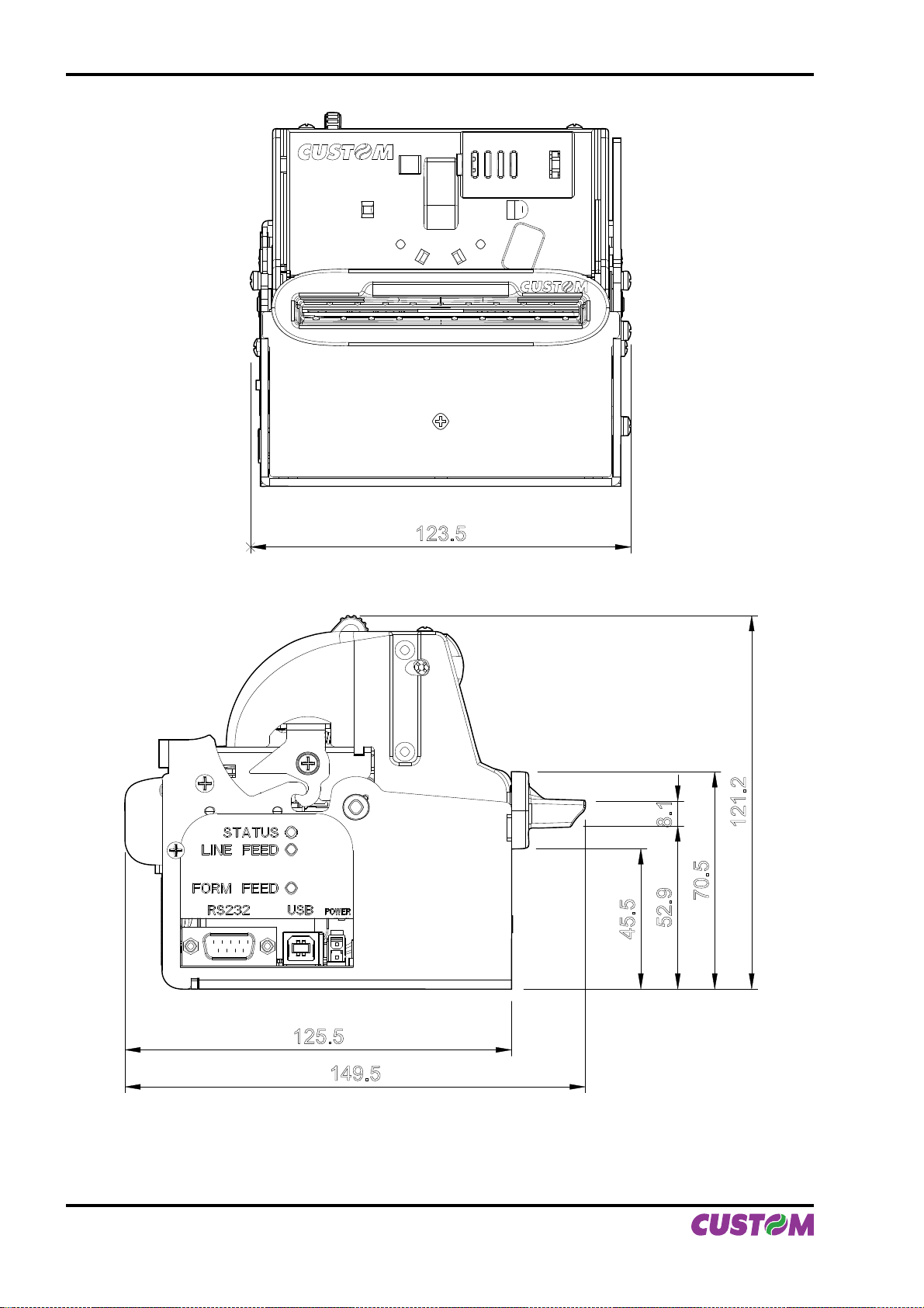
In the following fi gures shows the dimensions of the printer.
3 FIXING POINT (BOTTOM)
Bottom view
(Fig. 3.1)
3. TECHNICAL SPECIFICATIONS
Top view
(Fig. 3.2)
M4; n°3 thread
85.5
+0.5
-0.5
9.5
+0.5
-0.5
-0.5
+0.5
100
83 max usable
95
110
User Manual VKP80II 3-3
Page 30
3. TECHNICAL SPECIFICATIONS
Front view
(Fig. 3.3)
Left side view (SX)
(Fig. 3.4)
123.5
45.5
121.2
70.5
52.9 8.1
3-4 VKP80II User Manual
125.5
149.5
Page 31
4. CHARACTER SETS
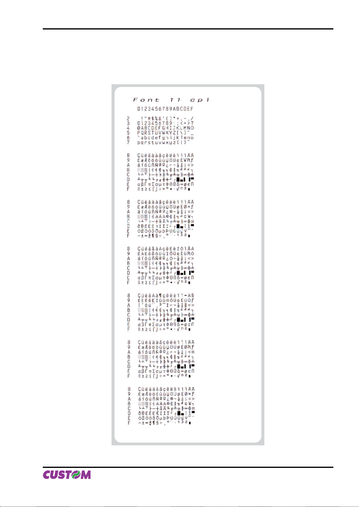
4.1 CHARACTER SETS
The printer has 3 fonts of varying width (11, 15 and 20 cpi) which may be accessed through programming
(section 1.2) or control characters. Each of these fonts offers the following code tables: PC437, PC850,
PC860, PC863, PC865, PC858. Shown below in fi gures 4.1 are examples of the 11 cpi character set.
PC437
(Usa, Standard, Europe)
PC850
(Multilingual)
PC860
(Portuguese)
PC863
(Canadian, French)
PC865
(Nordic)
PC858
(Euro symbol)
To print the Euro (€) symbol, the command sequence is: $1B, $74, $13, $D5.
(Fig.4.1)
User Manual VKP80II 4-1
Page 32

4. CHARACTER SETS
Blank page
4-2 VKP80II User Manual
Page 33
APPENDIX A - ACCESSORIES AND SPARE P ARTS
A.1 ACCESSORIES
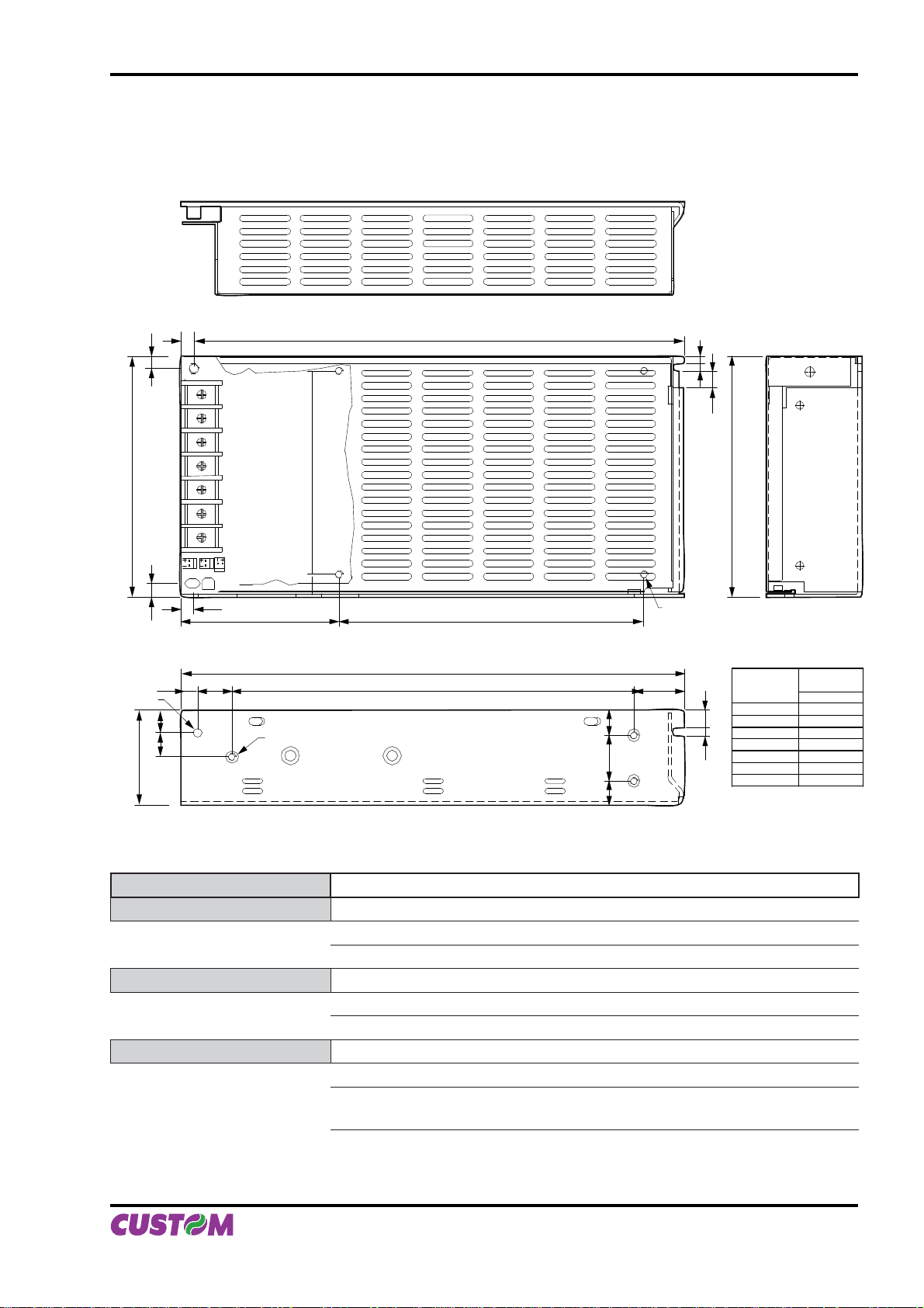
A.1.1 Power Supply
The fi gure below illustrates the power supply provided by Custom to be used for printer operation.
(Fig.A.1)
95.0
3.4 HOLE
38
5
5.5
FG
+V
+V
6.5
9.0
9.5
-V
-V
5
CN1
L
N
9.0
4.5
62.0
13.5
3 - M3 - P 0.5
193.0
198.0
158.0
120.0
10.0
18.0
10
4 - M3 - P 0.5
20.0
3
3
6.5
95.0
RANGE
< 8
7.03.5
8 25
25 80
80 250
250 800
800 2600
ANGULAR
Note : Dimensioni in mm
TOLERANCE
B
0.1
0.15
0.25
0.4
0.8
1.5
0.3°
PPSPS-100-24V Switching power supply 24V 100W
Input specifi cation Input voltage 85V ÷ 264V
Current 0A ÷ 4.5A
Input frequency 47Hz ÷ 63Hz
Output specifi cation Output voltage 24V
Output current 0A ÷ 4,5A
Effi ciency 80%
Environmental condition Operating temperature 0°C ÷ 70°C
Humidity 20% ÷ 85% Rh (w/o condensation)
Storage temperature / Humidity -10°C ÷ 75°C/
10% ÷ 95% (w/o condensation)
Protection devices: Shortcircuit, overload and overvoltage.
User Manual VKP80II A-1
(Tab.A.1)
Page 34
APPENDIX A - ACCESSORIES AND SPARE P ARTS
A.1.2 CD Full driver
DOCD-VKP80II
CD-ROM Full driver for VKP80II
FULL DRV
A.1.3 Adjustable paper holder support
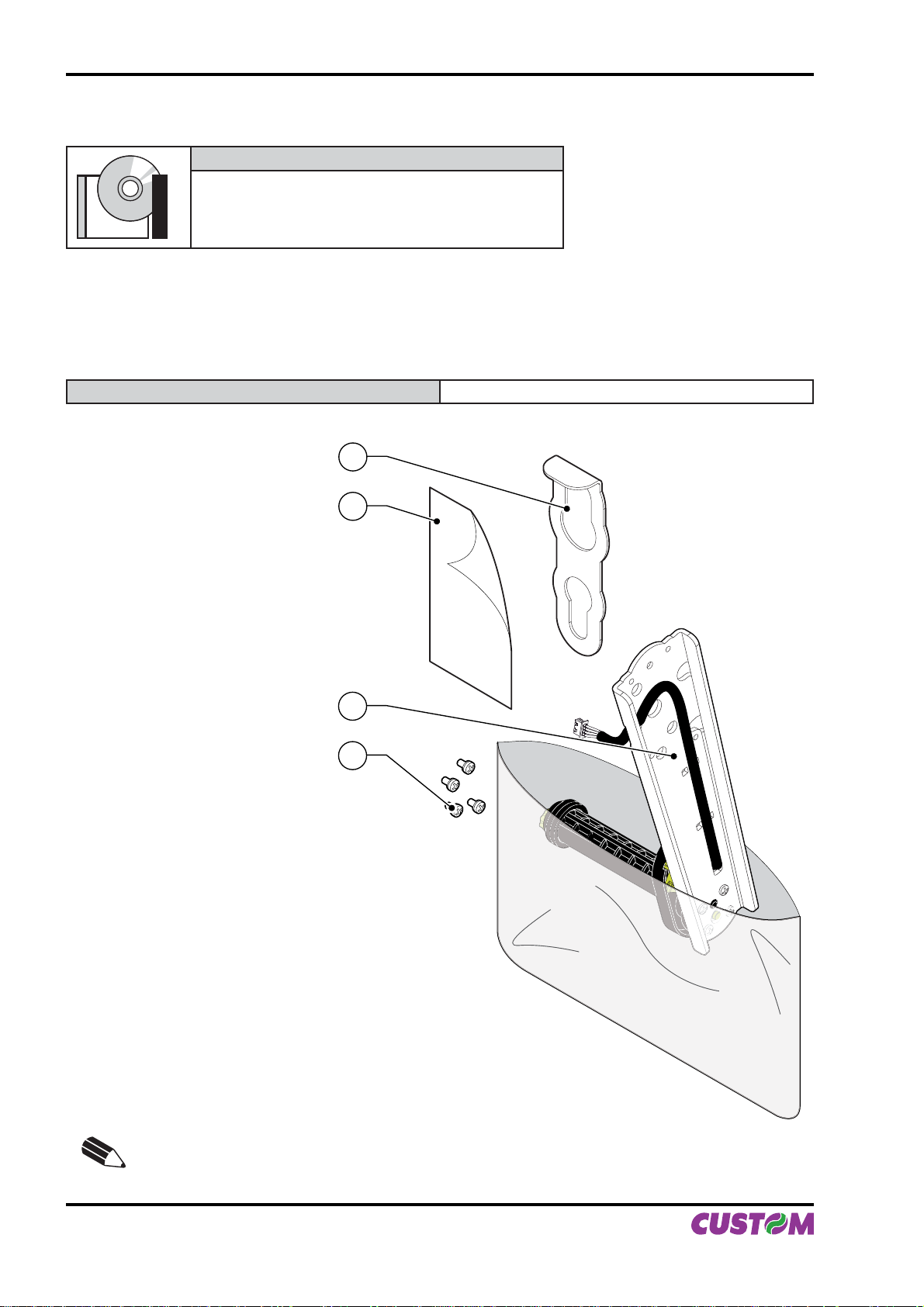
An adjustable paper holder support kit (see fi g. A.2) is available for the printer to make it possible to use
larger-width rolls of paper (130mm max.).
PCXSP-VKP80II Paper roll holder kit with sensor for VKP80II
The kit includes (see fi g. A.2) :
1 Tie for roll blocking
2 Instruction sheet
3 Paper holder support assembled
complete of:
- Near paper end sensor
- paper width regulating system
4 N°4 fastening screws
1
2
(Fig.A.2)
3
4
N.B.: Mounting the paper holder support using the instruction sheet enclosed with the kit.
A-2 VKP80II User Manual
Page 35
APPENDIX A - ACCESSORIES AND SPARE P ARTS
Assembly instructions
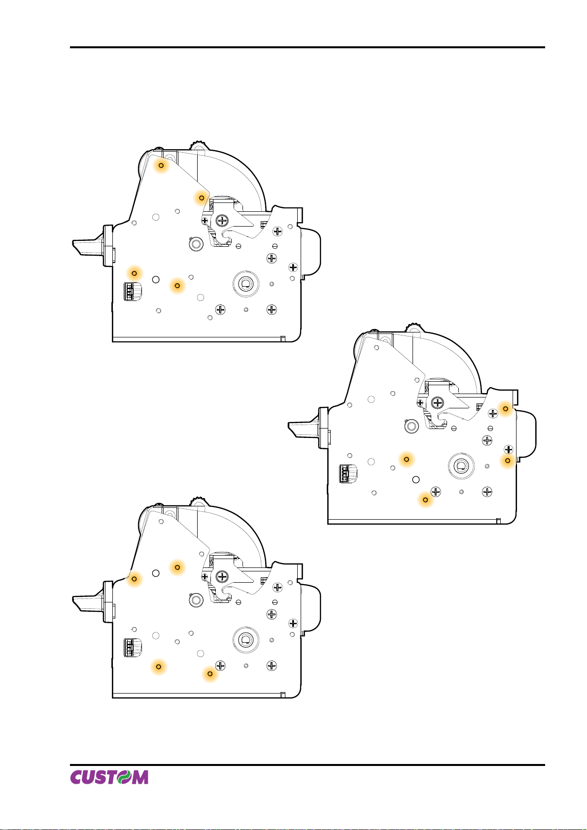
The position of the roll holder support is not fi xed and its rear, lower and upper position may be adjusted. The
support is attached to the printer frame at four points, as shown in fi gure A.3.
(Fig.A.3)
UPPER ATTACHMENT
REAR ATTACHMENT
LOWER ATTACHMENT
User Manual VKP80II A-3
Page 36
APPENDIX A - ACCESSORIES AND SPARE P ARTS
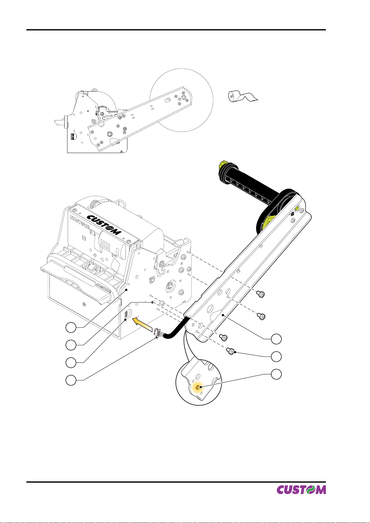
Rear attachment
(Fig.A.4)
Ø MAX = 180mm
1
2
3
4
Put the paper holder support near the printer body. Insert the point of reference (2) (paper holder sup-1.
port) into the hole (7) (printer body) (see fi g. A.5).
Attach the paper holder support (4) to the printer body (1) using four M4x8 screws (5) supplied with the 2.
kit (see fi g. A.5).
Insert the near paper end sensor connector (3) of the paper holder support into the connector of the sen-3.
sor card located on the printer (6) (see fi g. A.5).
(Fig.A.5)
7
6
5
A-4 VKP80II User Manual
Page 37
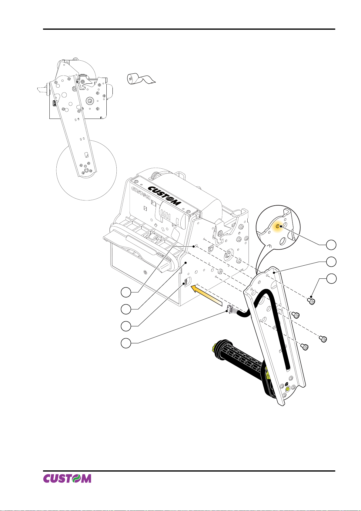
Lower attachment
APPENDIX A - ACCESSORIES AND SPARE P ARTS
Ø MAX = 180mm
(Fig.A.6)
(Fig.A.7)
1
2
3
4
Have the near paper end sensor connector (3) pass through the slit on the paper holder suport.1.
Insert the near paper end sensor connector (3) of the paper holder support into the connector of the sen-2.
sor card located on the printer (6).
Put the paper holder support near the printer body. Insert the point of reference (2) (paper holder sup-3.
port) into the hole (7) (printer body) (see fi g. A.7).
Attach the paper holder support (4) to the printer body (1) using four M4x8 screws (5) supplied with the 4.
kit (see fi g. A.7).
7
6
5
User Manual VKP80II A-5
Page 38
APPENDIX A - ACCESSORIES AND SPARE P ARTS
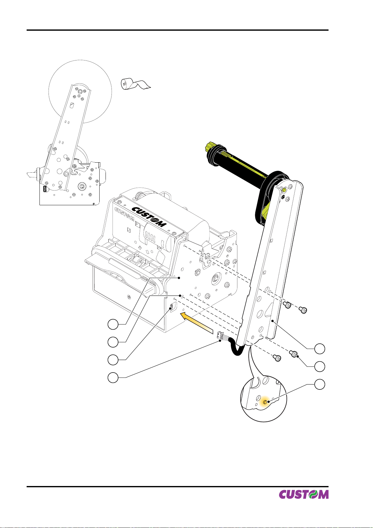
Upper attachment
Ø MAX = 170mm
(Fig.A.8)
(Fig.A.9)
1
2
3
4
Put the paper holder support near the printer body. Insert the point of reference (2) (paper holder sup-1.
port) into the hole (7) (printer body) (see fi g. A.9).
Attach the paper holder support (4) to the printer body (1) using four M4x8 screws (5) supplied with the 2.
kit (see fi g. A.9).
Insert the near paper end sensor connector (3) of the paper holder support into the connector of the sen-3.
sor card located on the printer (6) (see fi g. A.9).
7
6
5
A-6 VKP80II User Manual
Page 39
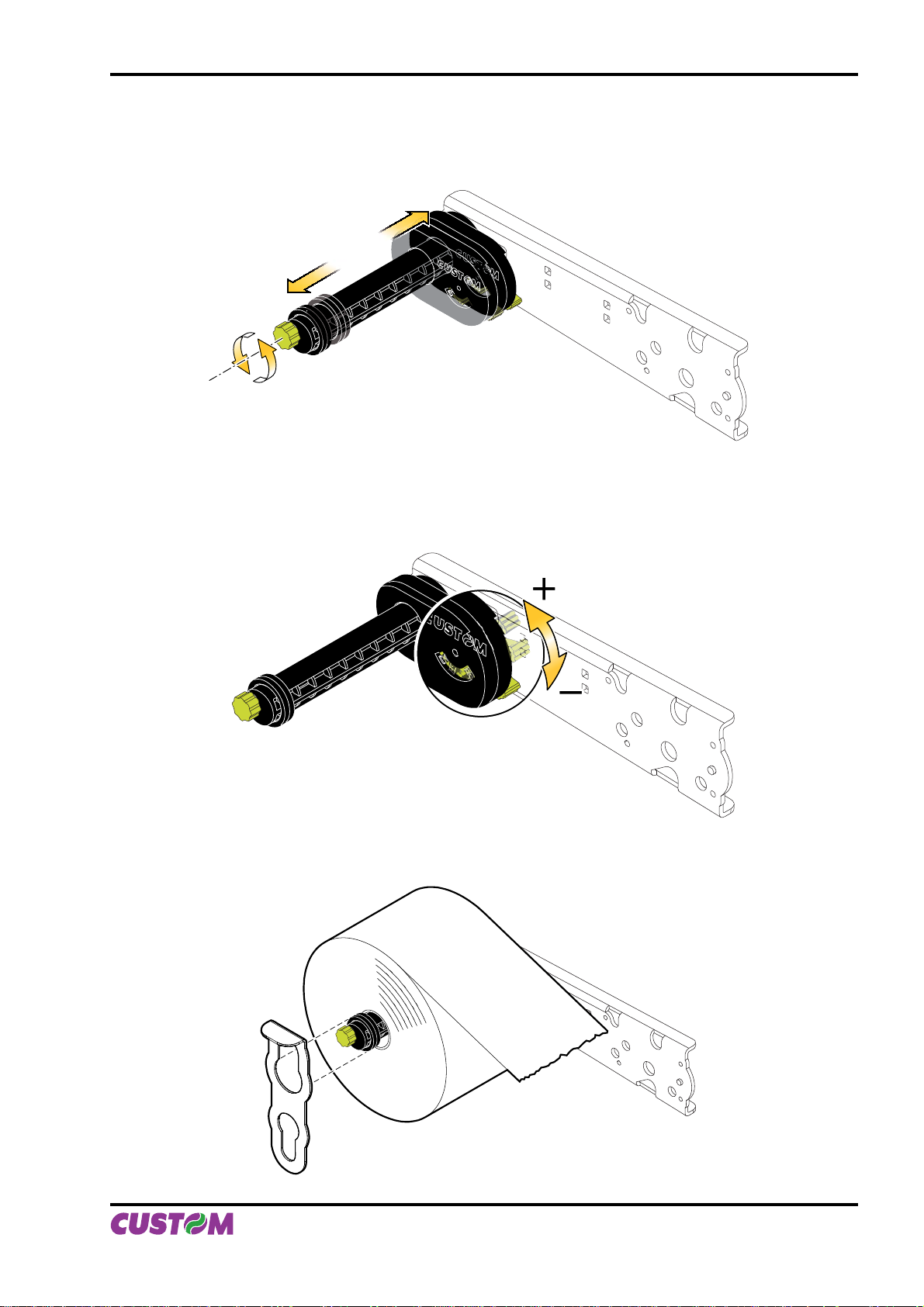
APPENDIX A - ACCESSORIES AND SPARE P ARTS
Paper width adjustment with roll holder support
Paper width may be set from 60mm to 82.5mm max. Rotate the knob to adjust the width of the housing for
paper roll (see fi g. A.10).
(Fig.A.10)
Near paper end adjustment
Rotate the lever to adjust the sensor position for nearly paper end. Move the lever up to in-crease the reserve of paper, move the lever down to decrease the reserve of paper (see fi g. A.11).
(Fig.A.11)
“Tie” for roll blocking
Insert the “tie” as shown in fi gure A.12 to avoid the paper roll come out accidentally from the pin.
(Fig.A.12)
User Manual VKP80II A-7
Page 40
APPENDIX A - ACCESSORIES AND SPARE P ARTS
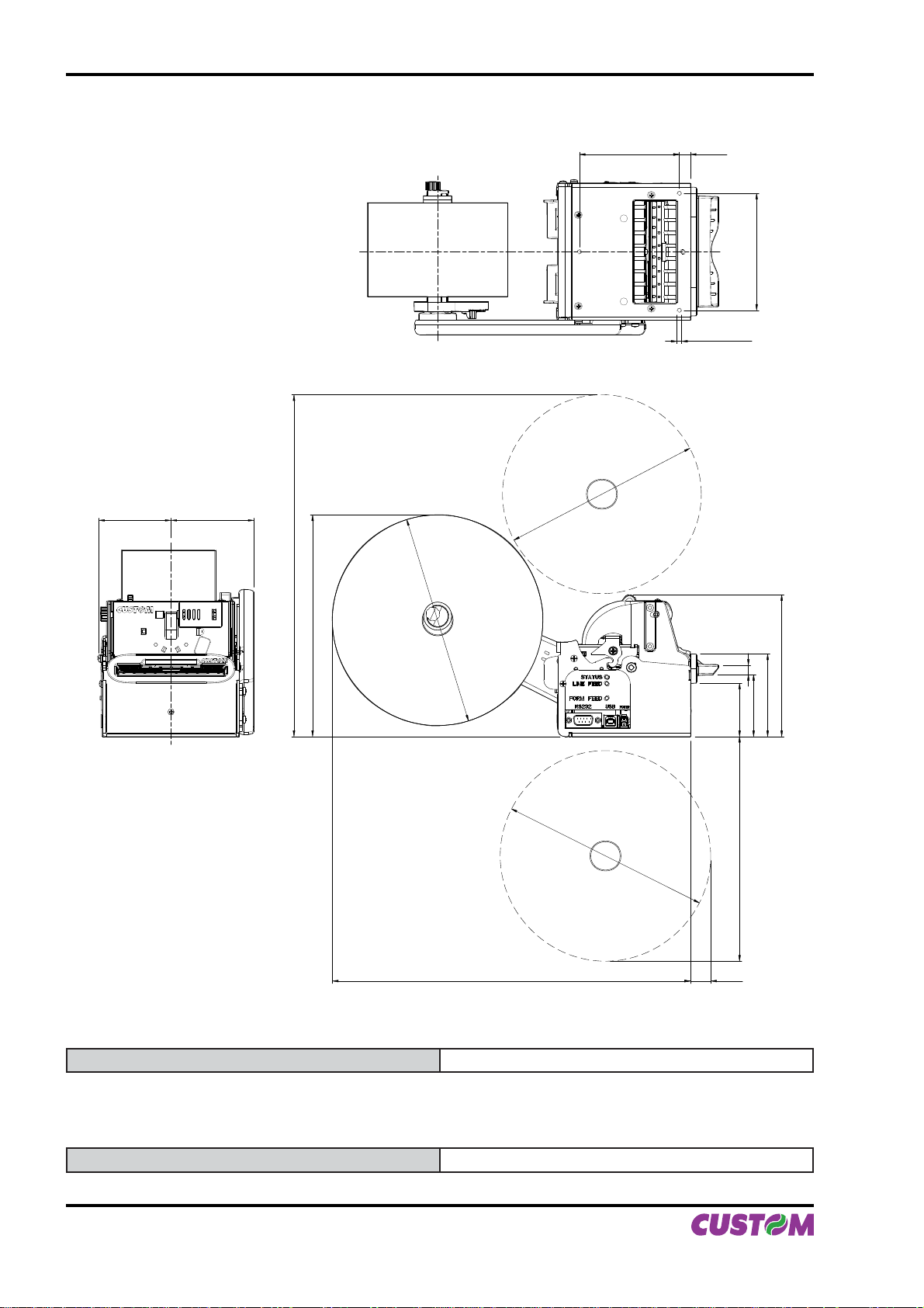
Printer dimensions with roll holder support
(Fig.A.13)
+0.5
85.5
-0.5
Ø170
7161.8
292.1
Ø180
+0.3
9.5
-0.3
M4; no. 3 holes
100
189.4
8.1
45.5
Ø180
306.2 17.3
192
A.2 SUPPLIES
RCT80X48-25MM-RS 80mm thermal paper roll back side pre-printed
52.9
121.2
70.5
Paper roll with paper holder support
RCT80X130-25MM Thermal paper roll 80mm
A-8 VKP80II User Manual
Page 41
APPENDIX A - ACCESSORIES AND SPARE P ARTS
A.3 NOTES FOR TECHNICAL ASSISTANCE
ATTENTION: The operations here described are exclusively aimed to the personnel handling
the technical assistance of the printer.
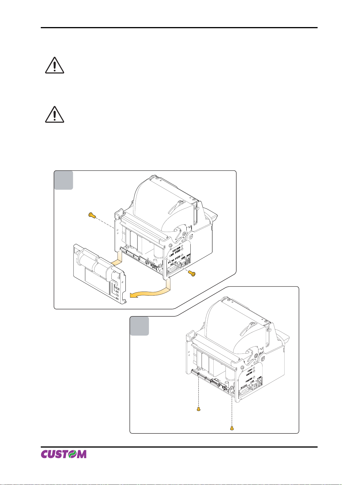
A.3.1 Replacing fuse
ATTENTION: Before replacing the fuse, it’s important to check up that the supply cable of the
printer is out.
The fuse is on the control board of the printer, near the supply connector (fi g. A.18), proceed as follows :
Unscrew the two fi xing screw for the back closing. Move back closing down and then remove as shown •
in fi g. A. 14.
Unscrew the two screws that fi xing control board to the chassis as shown in fi g. A.15.•
1
(Fig.A.14)
2
(Fig.A.15)
User Manual VKP80II A-9
Page 42
APPENDIX A - ACCESSORIES AND SPARE P ARTS
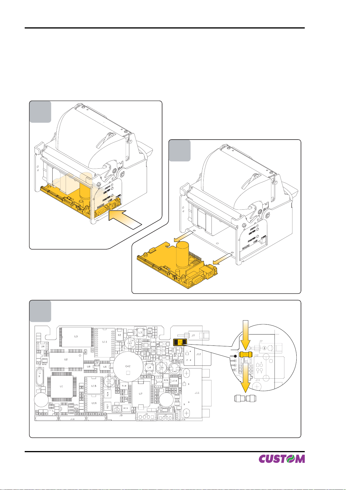
Make a note with the connectors position and then disconnect the connectors on the control board.•
Unlock the control board position pushing in the direction indicated by the arrow as shown in fi g. A.16.•
Extract the control board from its seating in the direction indicated by the arrow as shown in fi g. A.17.•
The fuse is on the control board of the printer, near the supply connector (fi g A.18). Unsolder the fuse at his •
end, paying attention to not heat excessively the closed components, to not take any risk to damage it.
Replace the fuse with a new one with same specifi cations (4A, 125V) and place it again in its seating.•
Reassemble the printer.•
3
4
(Fig.A.16)
5
(Fig.A.17)
(Fig.A.18)
A-10 VKP80II User Manual
Page 43

APPENDIX B - ALIGNMENT MANAGEMENT
B.1 TICKET ALIGNMENT
B.1.1 Ticket alignment
Paper with an alignment notch can be used in order to handle tickets with pre-printed fi elds and a fi xed
length.
To guarantee the alignment it is necessary that the “Notch Alignment” parameter is enabled from the key
setup (see setting confi guration parameters), that the alignment sensor is calibrated and that the parameters
are set.
The calibration of the sensor occurs automatically within the printer setup.
B.1.2 Enabling, calibrating and setting of parameters.
The notch sensor is a refl ection sensor that emits a band of light and detects the quantity of light refl ected to
it.
The presence of the notch is therefore detected by the amount of light that returns to the sensor, taking into
account that the light is refl ected by the white paper and absorbed by the black.
Calibration of the sensor occurs automatically and consists in adjusting the quantity of light emitted to adapt
it to the degree of whiteness of the paper used.
To start self-calibration, the “Notch Alignment” parameter will have to be enabled from the printer setup (see
setting confi guration parameters):
Notch Alignment : Enabled
The printer will perform some paper FEEDS, at the end of which it will print the value settings, for example:
Autosetting Notch : OK
Threshold White : 1.9V [39%]
The “Autosetting Notch” parameter indicates the operating condition of the self-calibration process; OK will
appear if it has been successful, but if it has failed the words NOT OK will appear.
In this case the default parameters concerning the “Threshold White” parameter will be set.
The “Threshold White” parameter indicates the power-up level of the sensor emitting side; its value ranges
from 0V to 5V with the corresponding value appearing as a percentage (from 0% to 100%).
Another parameter that needs to be set is the threshold:
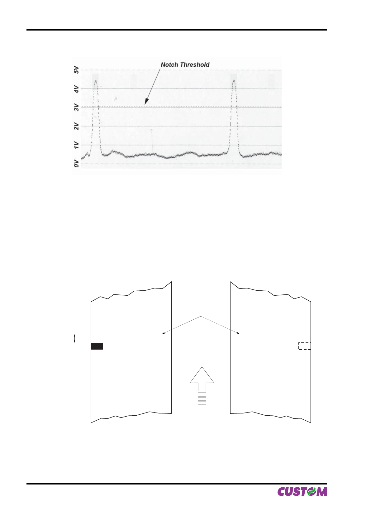
Notch Threshold.. : 3.0V
It is used to detect the presence of the notch: if the voltage value read by the sensor exceeds the threshold
value set the notch is identifi ed, otherwise the white paper is considered.
In order to better identify the optimum threshold for the paper being used, a paper characterisation function is
also available in setup.
Characterize Paper. :Yes
By activating this parameter the outgoing voltage of the sensor will be presented in a graphic form as shown
in fi gure B.1 below:
User Manual VKP80II B-1
Page 44
APPENDIX B - ALIGNMENT MANAGEMENT
PAPER CHARACTERIZATION
(Fig.B.1)
The graphic shows the references in Volts (from 0 to 5V) and the threshold value previously set. It is clear
that by adjusting the threshold value it is possible to fi nd the best position that takes into account the signal
peak and the small oscillations around zero.
The ALIGNMENT POINT is defi ned as the position inside the ticket that is the desired alignment point.
The ALIGNMENT POINT can be defi ned over the notch or near this one; for this reason, the fi nal param-
eters to be set in setup are:
Notch Dist. [mm x 10] . : 1
Notch Dist. [mm x 1] . : 5
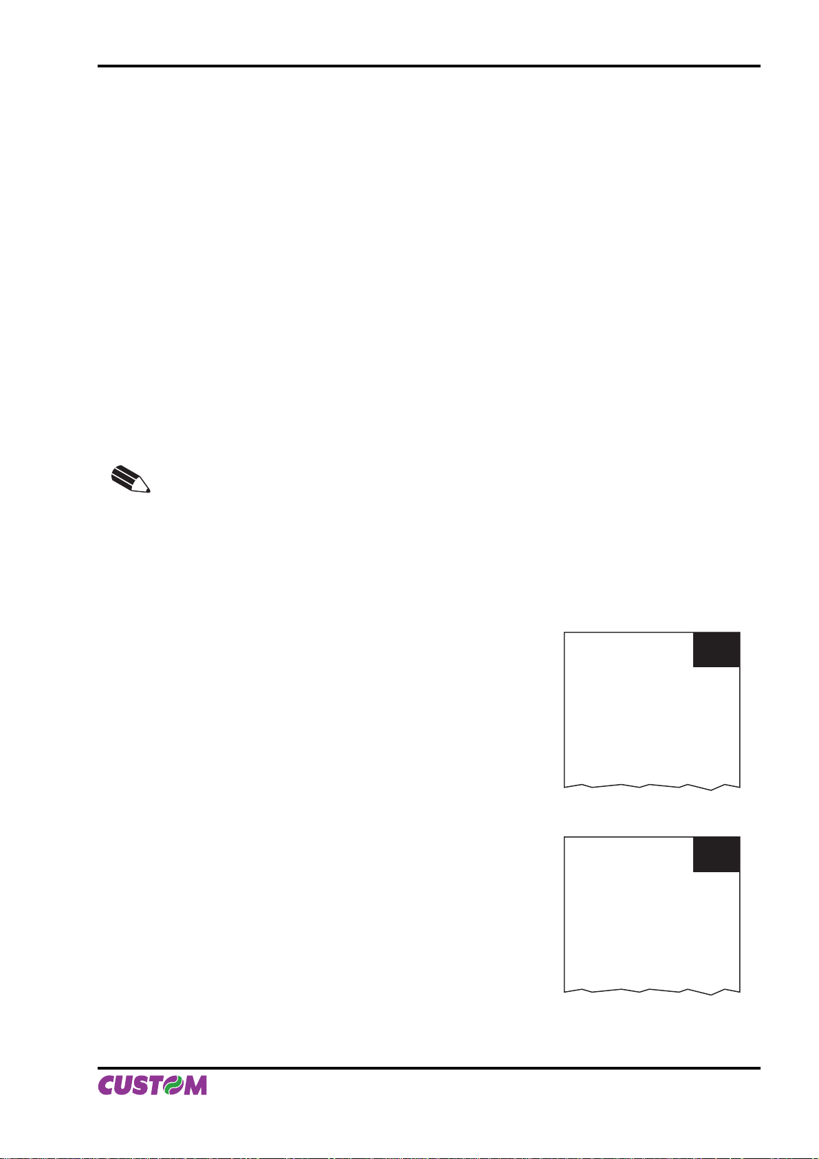
These parameters defi ne the “Notch Distance” that represents the distance from the notch to alignent; in the
above example the notch distance is 15 mm.
(Fig.B.2)
Alignment
point
Notch
Distance
NON HEAT
SENSITIVE Side
HEAT
SENSITIVE Side
Direction of
paper feed
Figure B2 shows how the “Notch Distance” parameter represents the distance that exists between the notch
and the desired alignment point. This parameter can have a minimum value of 0mm (in this case the alignments occur in proximity of the beginning of the notch) and a maximum of 32 mm. In reality the maximum
distance corresponds to the mechanical distance between the notch sensor and the head, and it is for this
reason that higher values are not permitted, and negative values are not envisaged.
B-2 VKP80II User Manual
Page 45
APPENDIX B - ALIGNMENT MANAGEMENT
B.2 COMMANDS
B.2.1 Ticket Alignment.
Two alignment commands are available: $1D $F6 and $1D $F8.
The command $1D $F6 performs an alignment to the print head: the paper is fed through until the print head
is at the fi rst available alignment point.
The command $1D $F8 on the other hand refers to the cutter: the paper is fed through until the cutter is at
the set alignment point, so that a subsequent cut will occur precisely at the alignment point.
Further explanations can be found in command documentation.
B.2.2 Setting the alignment distance.
The “Notch Distance” parameter can be changed via the printer setup or by using the command $1D $E7 nH
nL. For further information refer to the command itself.
B.2.3 Examples.
N.B.: To a better comprehension, in the following fi gures, the Notch is indicated on the same
side of the printing text.
Example 1.
To print a ticket’s sequence witch the cut is made over the notch it’s necessary set the notch distance to zero
as follows (this setting have effect after the ticket already in the printer):
{Set Notch Distance}
$1D,$E7,$00,$00,
{Print text}
‘TICKET 1’,$0A,’FIRST LINE’,$0A,’SECOND LINE’,$0A
{Cut alignment}
$1D, $F8,
{Cut}
ESC,’i’,
...
{Print text}
‘TICKET 1’,$0A,’FIRST LINE’,$0A,’SECOND LINE’,$0A
{Cut alignment}
$1D,$F8,
{Cut}
ESC,’i’,
...
TICKET N
FIRST LINE
SECOND LINE
TICKET (N+1)
FIRST LINE
SECOND LINE
(Fig.B.3)
User Manual VKP80II B-3
Page 46
APPENDIX B - ALIGNMENT MANAGEMENT
Example 2
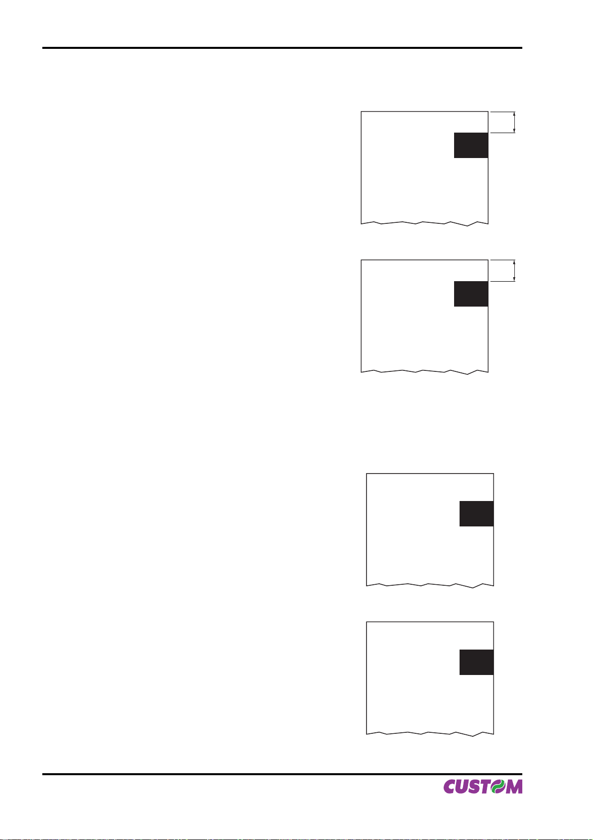
To cut 10 mm before the notch the command sequence is (this setting have effect after the ticket already in
the printer):
$1D, $E7, $00, $0A,
{Print text}
‘TICKET 1’,$0A,’FIRST LINE’,$0A,’SECOND LINE’,$0A
{Cut alignment}
$1D, $F8,
{Cut}
ESC,’i’,
...
TICKET N
FIRST LINE
SECOND LINE
10
10
{Print text}
‘TICKET 1’,$0A,’FIRST LINE’,$0A,’SECOND LINE’,$0A
{Cut alignment}
$1D,$F8,
{Cut}
ESC,’i’,
...
Example 3.
To print over the notch the command sequence is (this setting have effect after the ticket already in the
printer):
{Set Notch Distance}
$1D,$E7,$00,$00,
{Print text}
‘TICKET 1’,$0A,’FIRST LINE’,$0A,’SECOND LINE’,$0A
{Cut}
ESC,’i’
...
TICKET (N+1)
FIRST LINE
SECOND LINE
(Fig.B.4)
TICKET N
FIRST LINE
SECOND LINE
{Set Notch Distance}
$1D,$E7,$00,$00,
{Print text}
‘TICKET 1’,$0A,’FIRST LINE’,$0A,’SECOND LINE’,$0A
{Cut}
ESC,’i’,
...
B-4 VKP80II User Manual
TICKET (N+1)
FIRST LINE
SECOND LINE
(Fig.B.5)
Page 47
APPENDIX B - ALIGNMENT MANAGEMENT
Example 4.
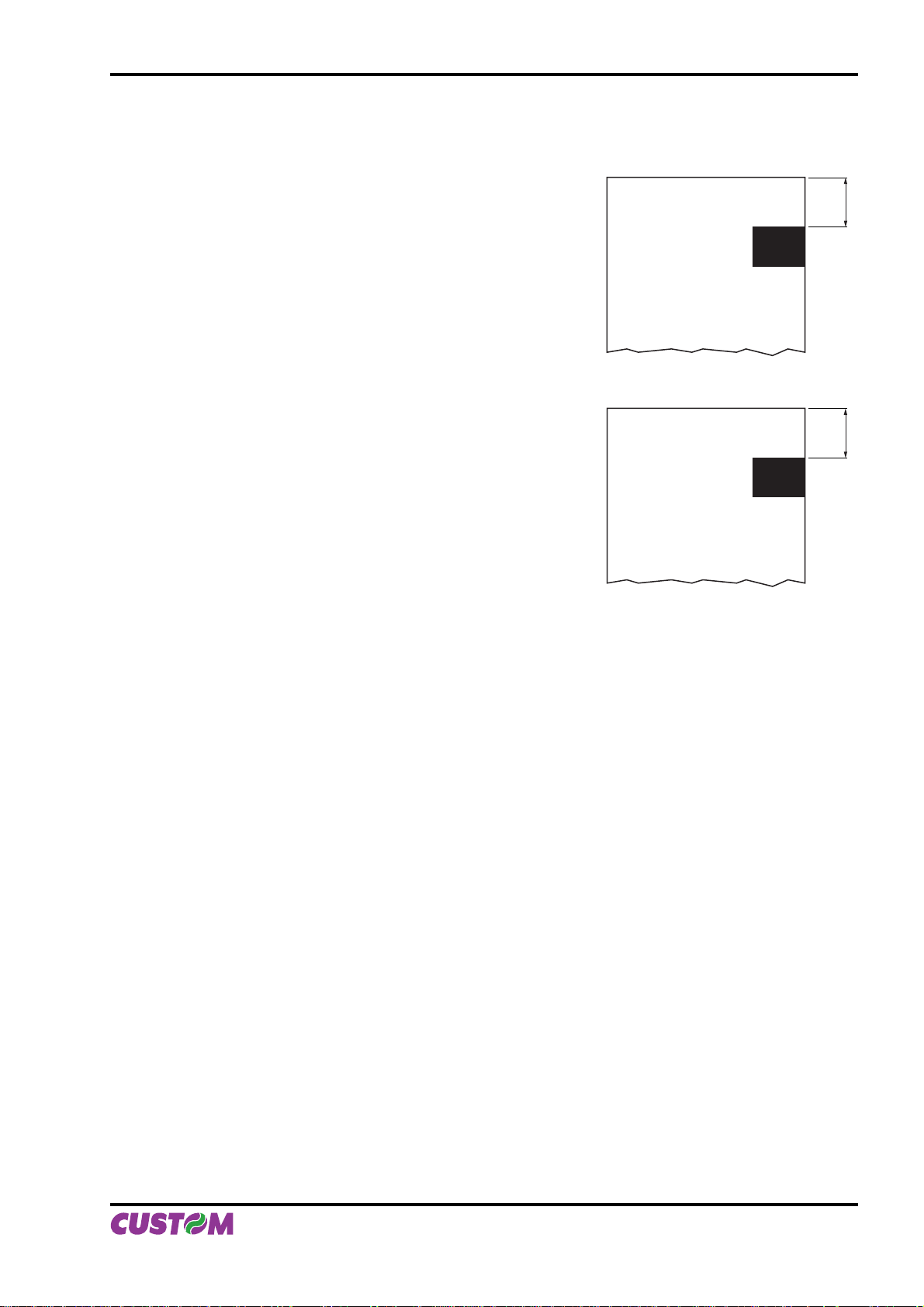
To print 15 mm before the notch the command sequence is (this setting have effect after the ticket already in
the printer):
TICKET N
{Set Notch Distance}
$1D,$E7,$00,$00,
{Print text}
‘TICKET 1’,$0A,’FIRST LINE’,$0A,’SECOND LINE’,$0A
{Cut alignment}
$1D, $F8,
{Cut}
ESC,’i’,
...
FIRST LINE
SECOND LINE
15
{Print text}
‘TICKET 1’,$0A,’FIRST LINE’,$0A,’SECOND LINE’,$0A
{Cut alignment}
$1D,$F8,
{Cut}
ESC,’i’,
TICKET (N+1)
FIRST LINE
SECOND LINE
(Fig.B.6)
15
User Manual VKP80II B-5
Page 48
APPENDIX B - ALIGNMENT MANAGEMENT
B.3 CHARACTERISTICS OF THE PAPER.
B.3.1 Dimensions and position of the notch.
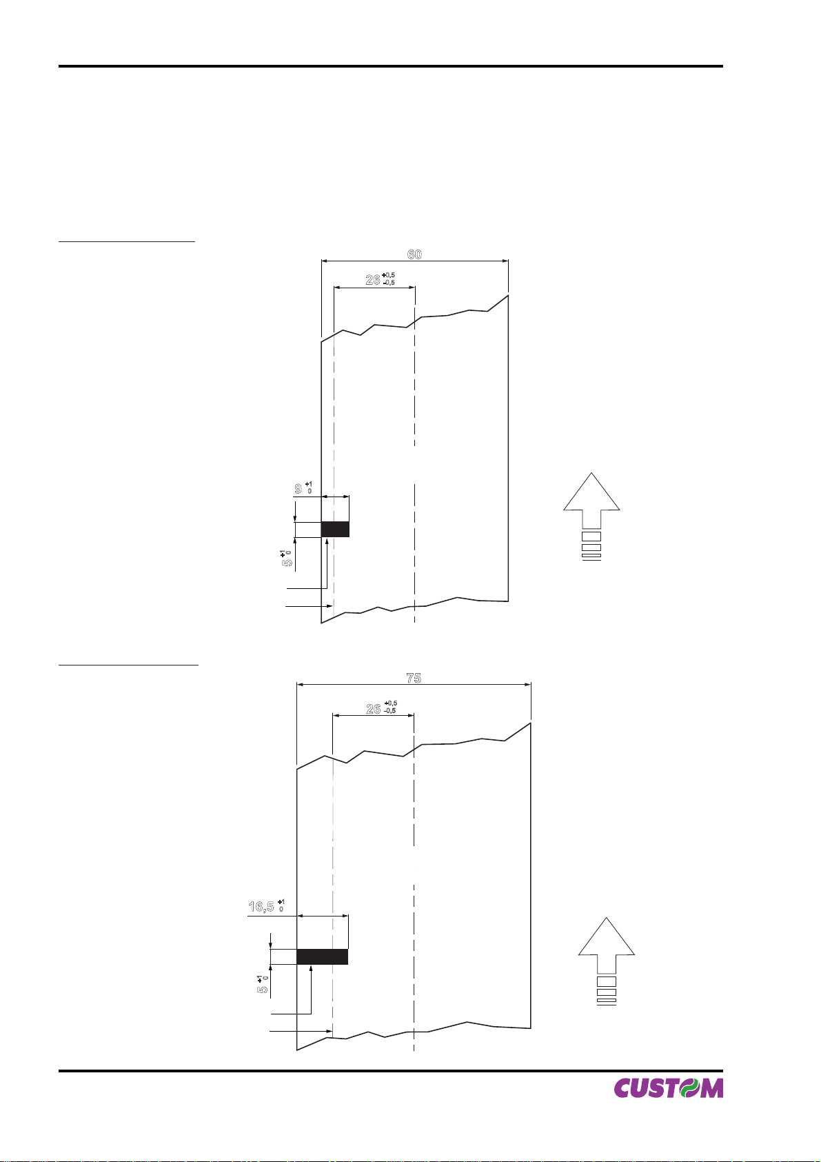
The notch must be positioned on the non-heat sensitive side of the paper as shown in fi gures B.7, B.8, B.9
and B.10, showing some fac-similes of paper with alignment notch depending on the width of the paper
used.
Notch on 60mm paper
60
+0,5
26
-0,5
Notch sensor axis
Notch on 75 mm paper
Black notch
NON HEAT
+1
0
9
0
+1
5
SENSITIVE Side
75
+0,5
-0,5
26
Direction
of paper
feed
(Fig.B.7)
16,5
Black notch
Notch sensor axis
B-6 VKP80II User Manual
NON HEAT
SENSITIVE Side
+1
0
0
+1
5
Direction
of paper
feed
(Fig.B.8)
Page 49
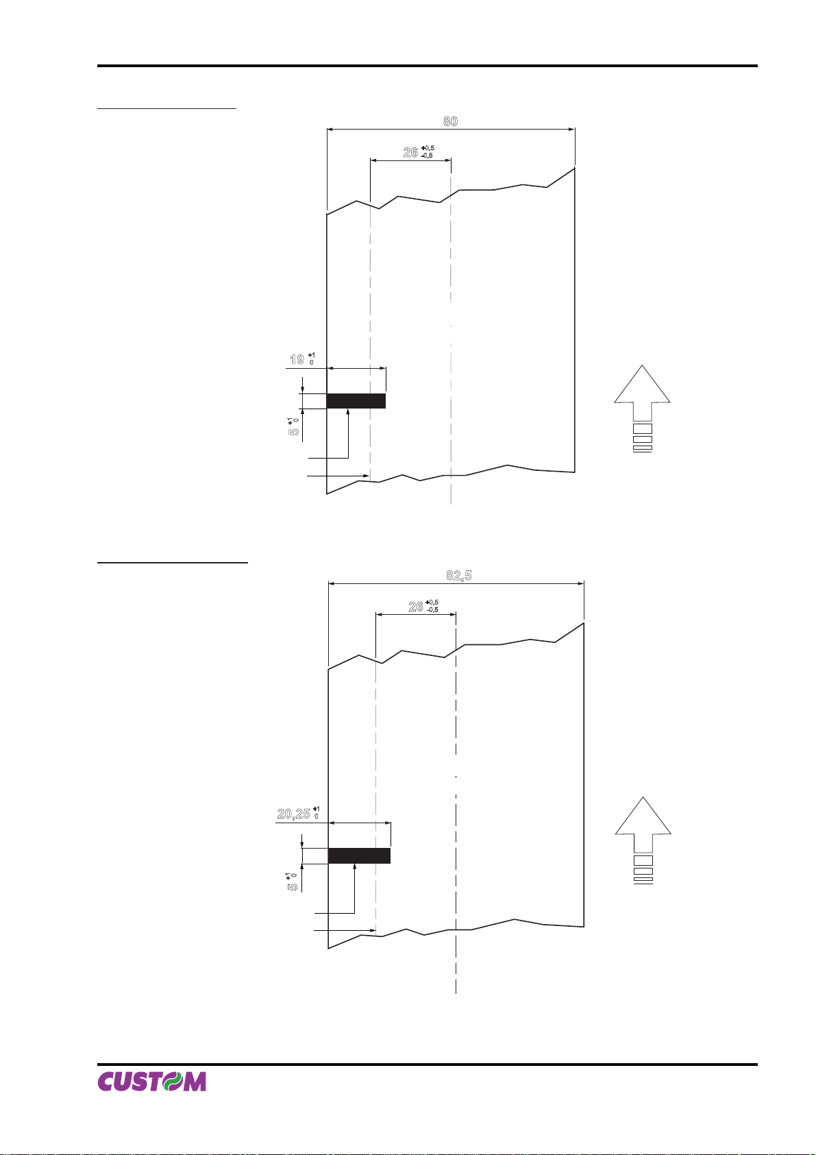
Notch on 80 mm paper
19
+1
APPENDIX B - ALIGNMENT MANAGEMENT
80
+0,5
26
-0,5
NON HEAT
SENSITIVE Side
+1
0
0
5
Black notch
Notch sensor axis
Notch on 82,5 mm paper
20,25
Direction
of paper
(Fig.B.9)
feed
82,5
+0,5
26
-0,5
NON HEAT
SENSITIVE Side
+1
0
0
+1
5
Black notch
Notch sensor axis
Direction
of paper
feed
(Fig.B.10)
User Manual VKP80II B-7
Page 50
APPENDIX B - ALIGNMENT MANAGEMENT
B.3.2 Position of sensors
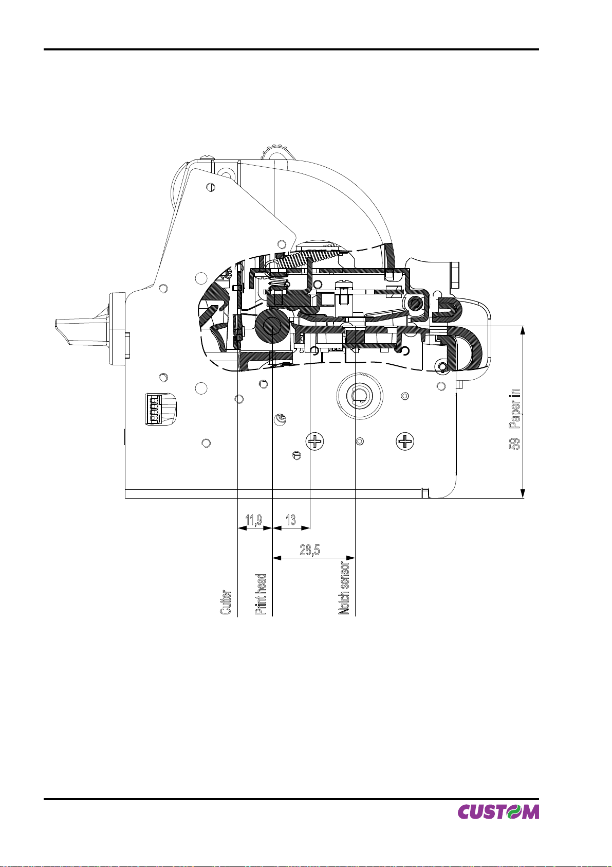
Figure B.11 shows a section of the printer and the distances between the head, the cutter and the notch sensor.
(Fig.B.11)
11,9
13
28,5
Cutter
Figure B.11 clearly shows why the alignment distance (Notch Distance) cannot exceed the notch sensorhead distance. The moment that the notch sensor detects a notch, the head is already mechanically positioned 32 mm upstream of the of the notch in order therefore for it to align itself with this notch, as a reference the paper can only be fed forward, and so reduce the distance already there.
Print head
Notch sensor
59 Paper in
B-8 VKP80II User Manual
Page 51
APPENDIX B - ALIGNMENT MANAGEMENT
B.3.3 Dimension of tickets
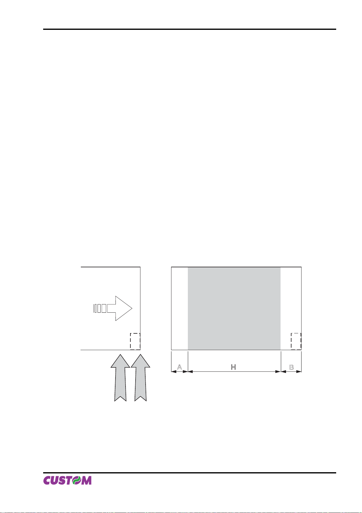
It is very important to well calibrate the height of the printer area, according to the distance between the two
edges of the notch.
In order not to miss a notch (a ticket must therefore contain only one notch) the following equation must be
used:
INTER-NOTCH DISTANCE>PRINTED AREA HEIGHT + NON-PRINTABLE AREA
where
INTER-NOTCH DISTANCE = the distance between two notch edges
NON-PRINTABLE AREA = cutter-head distance
The picture in fi gure B.12 shows a sequence of printed tickets aligning each one at the cut. It can be noted
that increasing the printed area will result in superimposing what is to be printed at the subsequent notch.
The size of the print area can be enlarged until it renders the alignment feed void, but not beyond. It is very
important never to forget about the non-printable area that corresponds to the cutter-head distance and is the
result of every cut.
LEGEND:
A = Alignment feed
H = Printing area height
B = Non printable area (CUTTER - PRINT HEAD)
PAPER IN
THE PRINTER
Direction of paper
A
TICKET
PRODUCED
Printing area
H
B
CUTTER
PRINT HEAD
(Fig.B.12)
User Manual VKP80II B-9
Page 52
APPENDIX B - ALIGNMENT MANAGEMENT
B.4 METHODS OF USAGE
B.4.1 Command sequences
It is possible, when printing sequences of tickets, to primarily identify two different methods of operation that
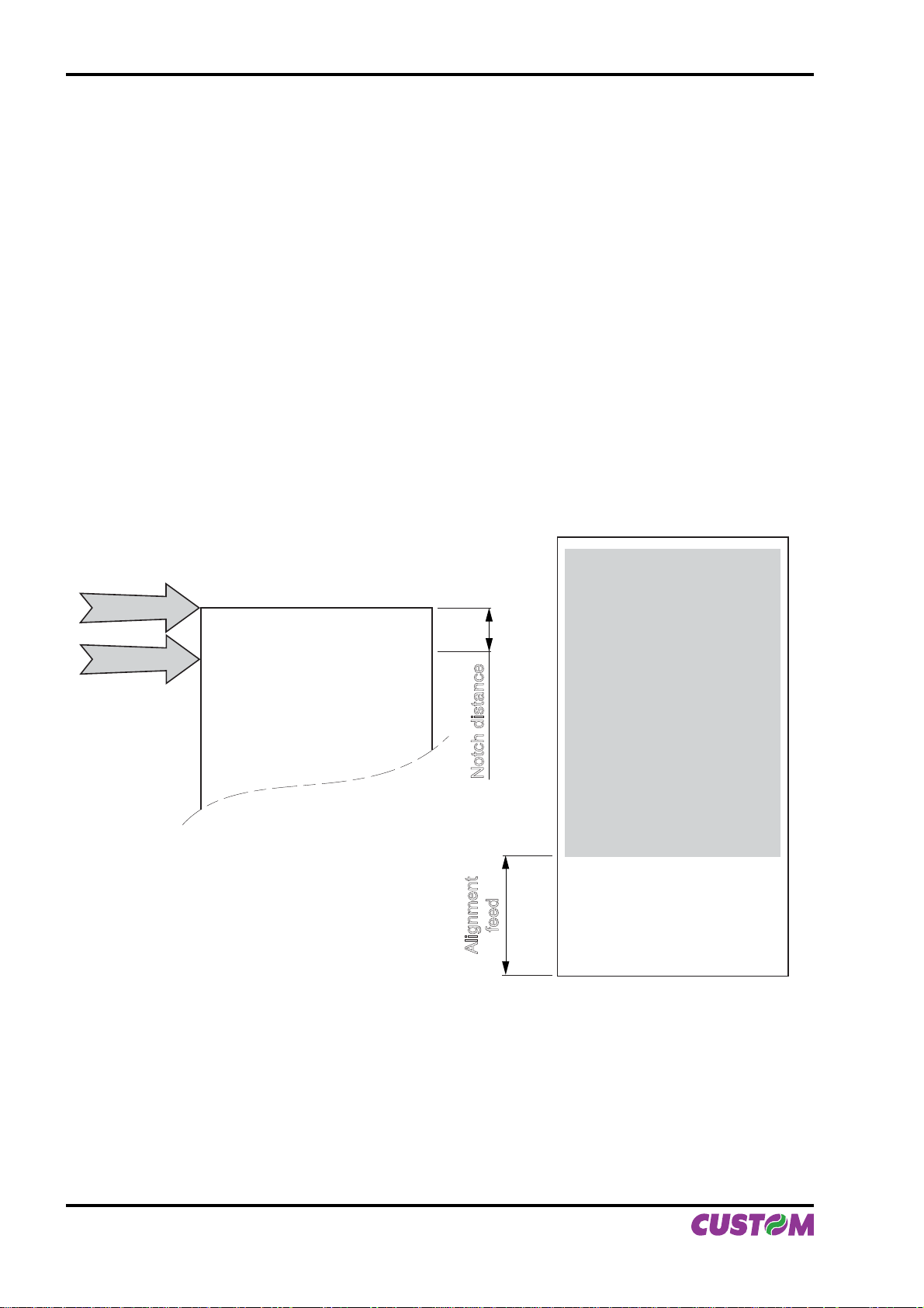
involve the alignment: ticket aligned at the cut and ticket aligned at printing.
Another very important aspect to bear in mind is the condition from which printing commences. In fi gure
B.12, that shows a ticket aligned at the cut, it can be seen how every time a ticket printing begins this originates from an alignment at the cut, and therefore the distance between the start of the print area and the
alignment line is equal to the head-cutter distance. The same situation applies to an alignment at printing.
B.4.1.1 Alignment at the cut
The sequence of commands to be entered when wanting to align a ticket at the cut is as follows:
1. Ticket general setting; formatting of characters, print density, margins etc.
2. Print ticket: Printing of text, logos or any other graphics.
3. Alignment at the cut command: $1D $F8
4. Cut command
The result is shown in fi gure B.13.
CUTTER
PRINT HEAD
(Fig.B.13)
PAPER IN
THE PRINTER
Printed area
Notch distance
feed
Alignment
It is possible to see how the start of the ticket print area is not aligned, but the print starts in the rest position
that the head took up at the moment the previous ticket was cut. At the end of the print area the printer has
fed the paper through to align itself and perform the cut at the desired position.
B-10 VKP80II User Manual
Page 53
APPENDIX B - ALIGNMENT MANAGEMENT
B.4.1.2 Alignment at printing
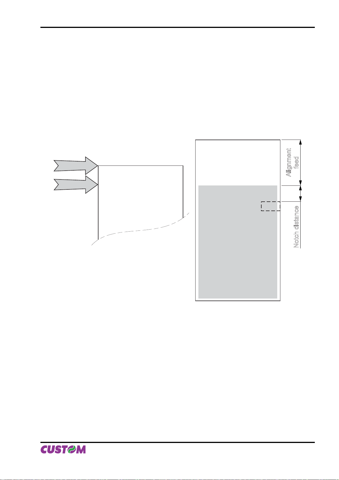
Alignment at printing requires the following sequence of commands:
1. Ticket general setting; formatting of characters, print density, margins etc.
2. Print alignment commands: $1D $F6
3. Print ticket: Printing of text, logos or any other graphics.
4. Cut commands
The result is shown in fi gure B.14.
Unlike the previous case, the alignment feed takes place before the start of printing, so as to align the print
area in the position required.
CUTTER
PRINT HEAD
(Fig.B.14)
feed
Alignment
PAPER IN
THE PRINTER
Printed area
Notch distance
User Manual VKP80II B-11
Page 54

APPENDIX B - ALIGNMENT MANAGEMENT
Blank page
B-12 VKP80II User Manual
Page 55

Page 56

Part Number : DOME-VKP80II Rev. 1.35
CUSTOM ENGINEERING SPA
World Headquarters
Via Berettine, 2 - 43010 Fontevivo, Parma ITALY
Tel. +39 0521 680111 - Fax +39 0521 610701
[email protected] - www.custom.biz
All rigths reserved
www.custom.biz
 Loading...