

Page 1
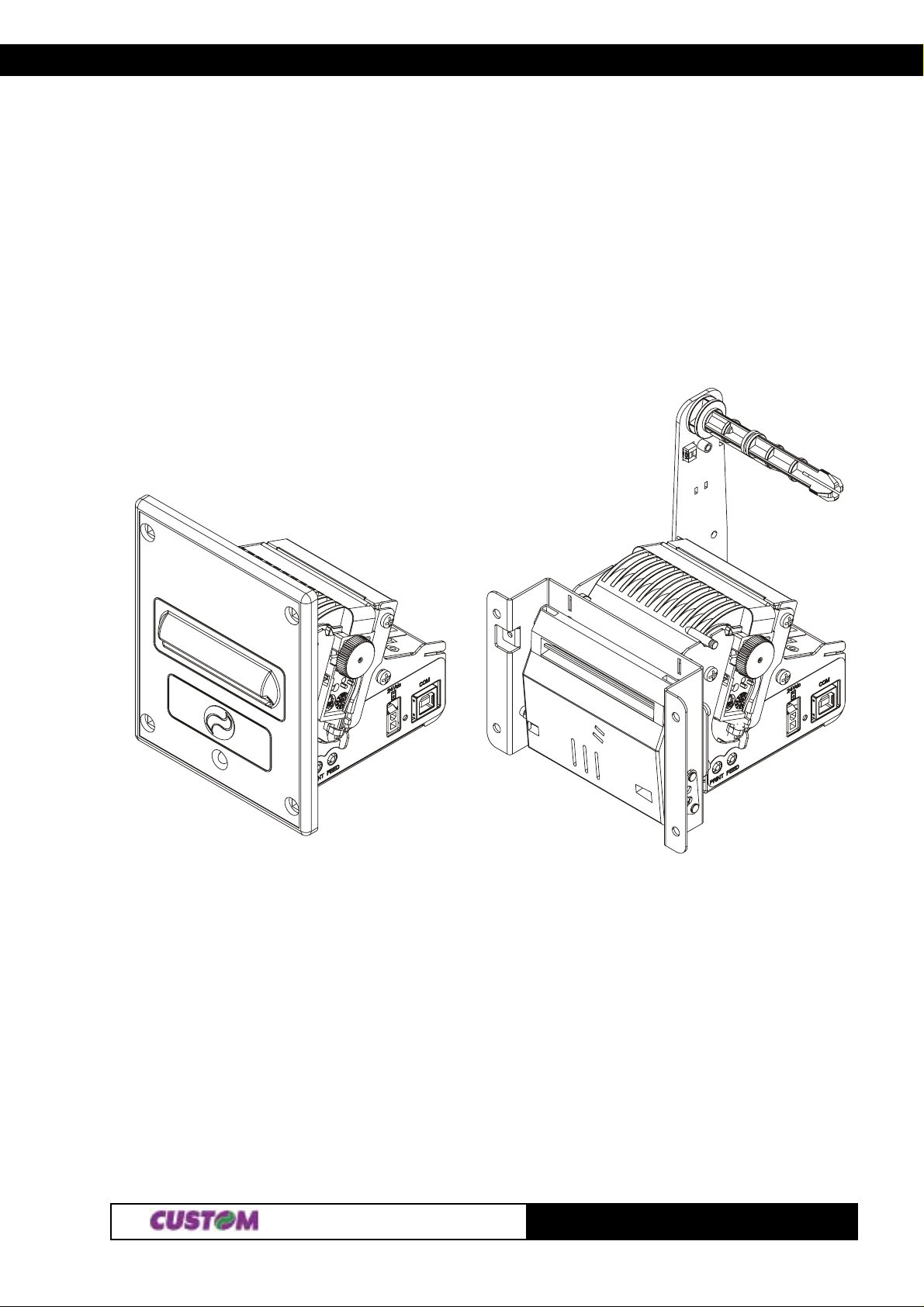
TICKET PRINTER
TG1260 series
TG2460 series
60 mm
User Manual
www .custom.it
TG1260/2460
Page 2

All rights reserved. T ot al or even partial reproduction of this manual in any form, whether on paper or electronically ,
is strictly forbidden. While CUSTOM ENGINEERING SP A guarantees that the information cont ained in this manual
has been carefully checked and verified, CUSTOM ENGINEERING SP A and other resources utilized in its creation
assume no responsibility for situations arising from its use.
Feedback regarding any errors in the manual’s content or suggestions on how it could be improved would be
greatly appreciated. Since its products are subject to continuous checking and improvement, CUSTOM
ENGINEERING SP A reserves the right to modify the information cont ained in this manual without prior notice.
COD. DOME - TG2460 VERS. 1.30
Copyright 2004 CUST OM ENGINEERING SP A – It aly
CUSTOM ENGINEERING SP A
Str . Berettine 2 - 43010 Fontevivo (P ARMA) - Italy
Phone : +39 0521-68011 1 - Fax : +39 0521-610701
http: www.custom.biz
T o cont act our Technical Support :
Email : [email protected]
TG1260/2460
Page 3
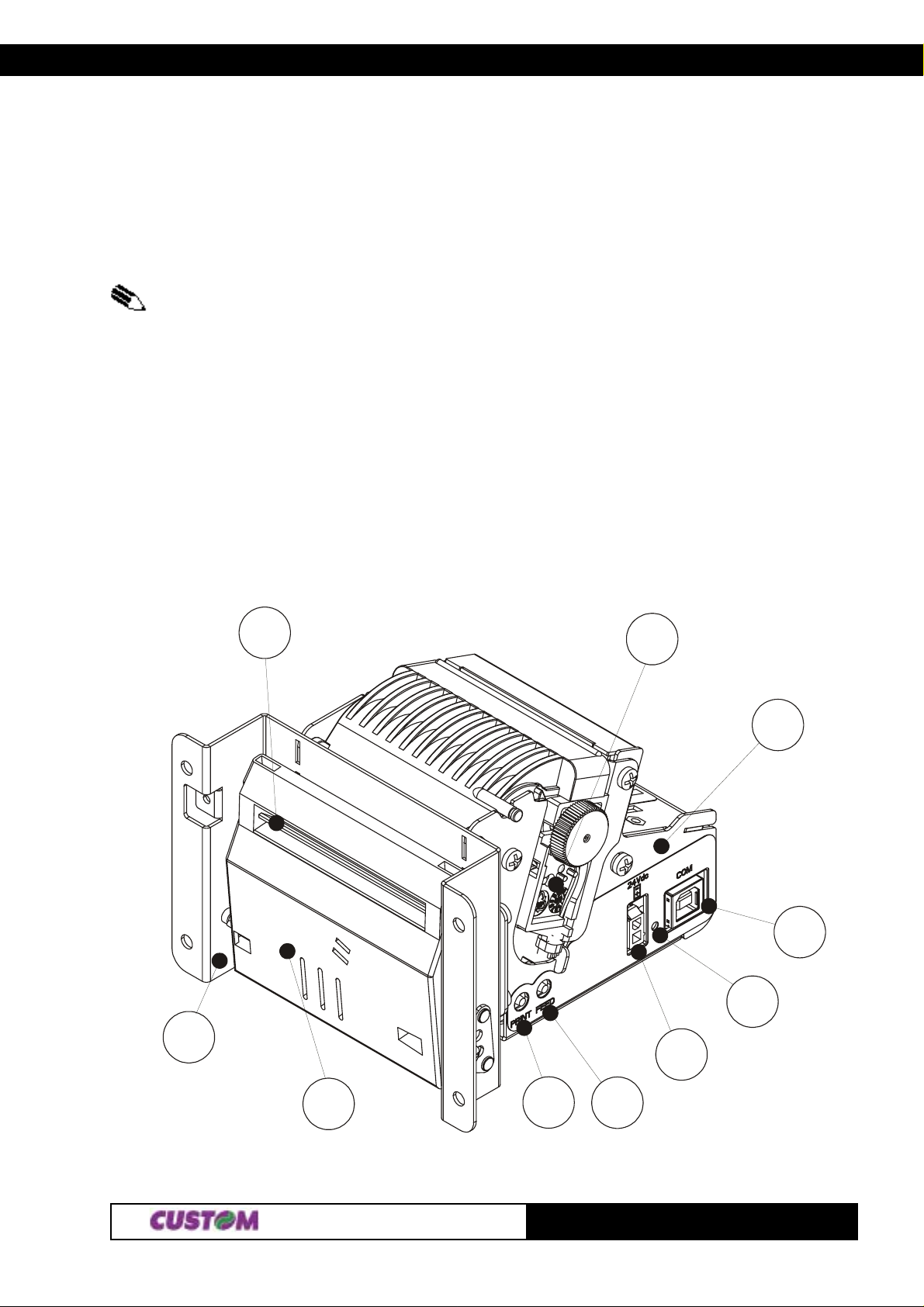
PRINTER COMPONENTS
The figures showed list printer parts with USB interface but the remarks are good for the RS232 interface
printers too (apart from the connector).
A. TG1260/TG2460-x-A
(1)
The x suffix indicates the following models :
-TG1260/TG2460-U-A: USB interface, metal front panel and autocutter model.
-TG1260/TG2460-S-A: RS232 serial interface, metal front panel and autocutter model.
‘1- Printing mechanism
2- Autocutter
3- “Print” key
4- “Feed” key
5- Power supply connector
6- USB interface connector
7- Printer frame
8- Autocutter support plate
9- Paper output
10 - Status led
9
(1)
External view
1
8
2
3
7
6
10
5
4
TG1260/2460
Page 4
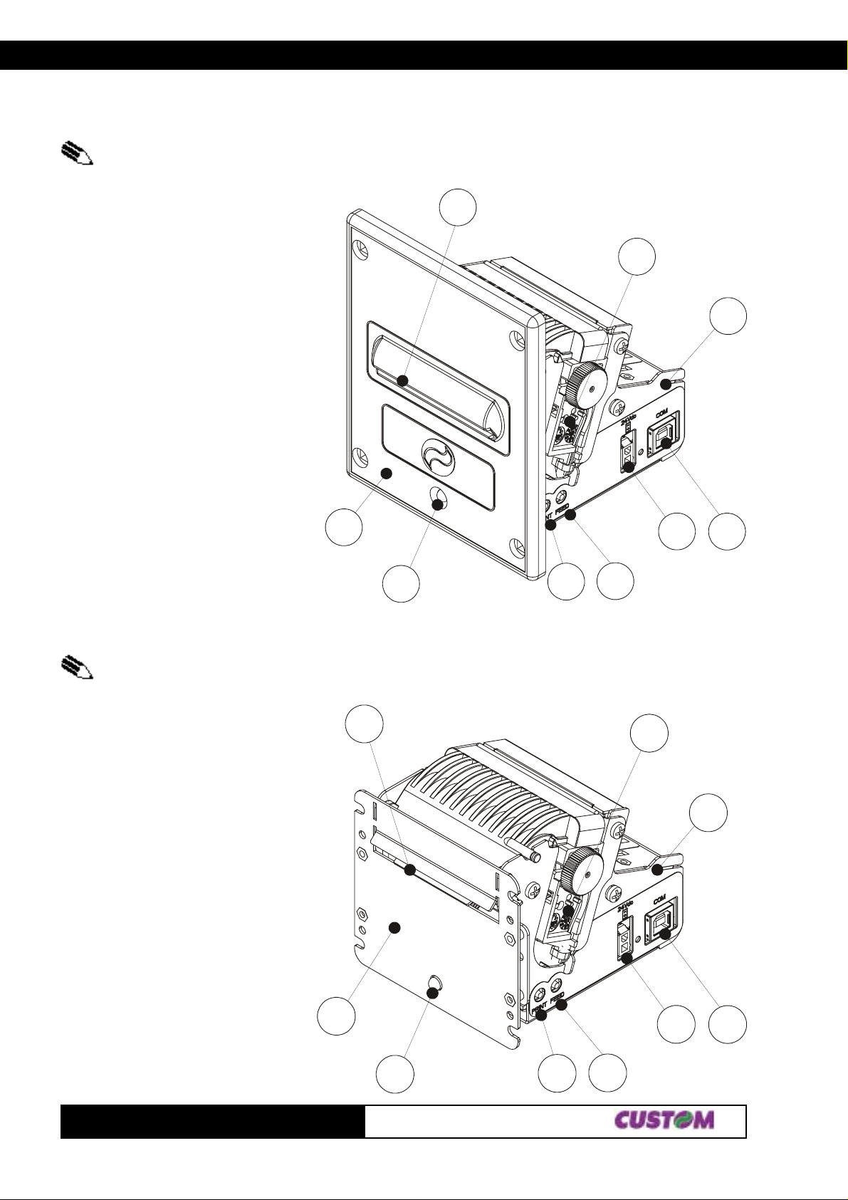
B. TG1260/TG2460-x-P
(2)
The x suffix indicates the following models :
- TG1260/TG2460-U-P: USB interface and plastic front panel.
- TG1260/TG2460-S-P: RS232 serial interface and plastic front panel.
(2)
external view
1- Printing mechanism
2- “Print” key
3- “Feed” key
4- Power supply connector
5- USB interface connector
6- Printer frame
7- Plastic front panel
8- Paper output
9- Status Led
C. TG1260/TG2460-x-M
(3)
external view
7
9
8
2
3
1
4
6
5
(3)
The x suffix indicates the following models :
- TG1260/TG2460-U-M: USB interface and metal front panel without autocutter model.
- TG1260/TG2460-S-M: RS232 serial interface and metal front panel without autocutter model.
1- Printing mechanism
2- “Print” key
3- “Feed” key
4- Power supply connector
5- USB interface connector
6- Printer frame
7- Metal front panel
8- Paper output
9- Status Led
7
8
1
4
6
5
TG1260/2460
9
2
3
Page 5
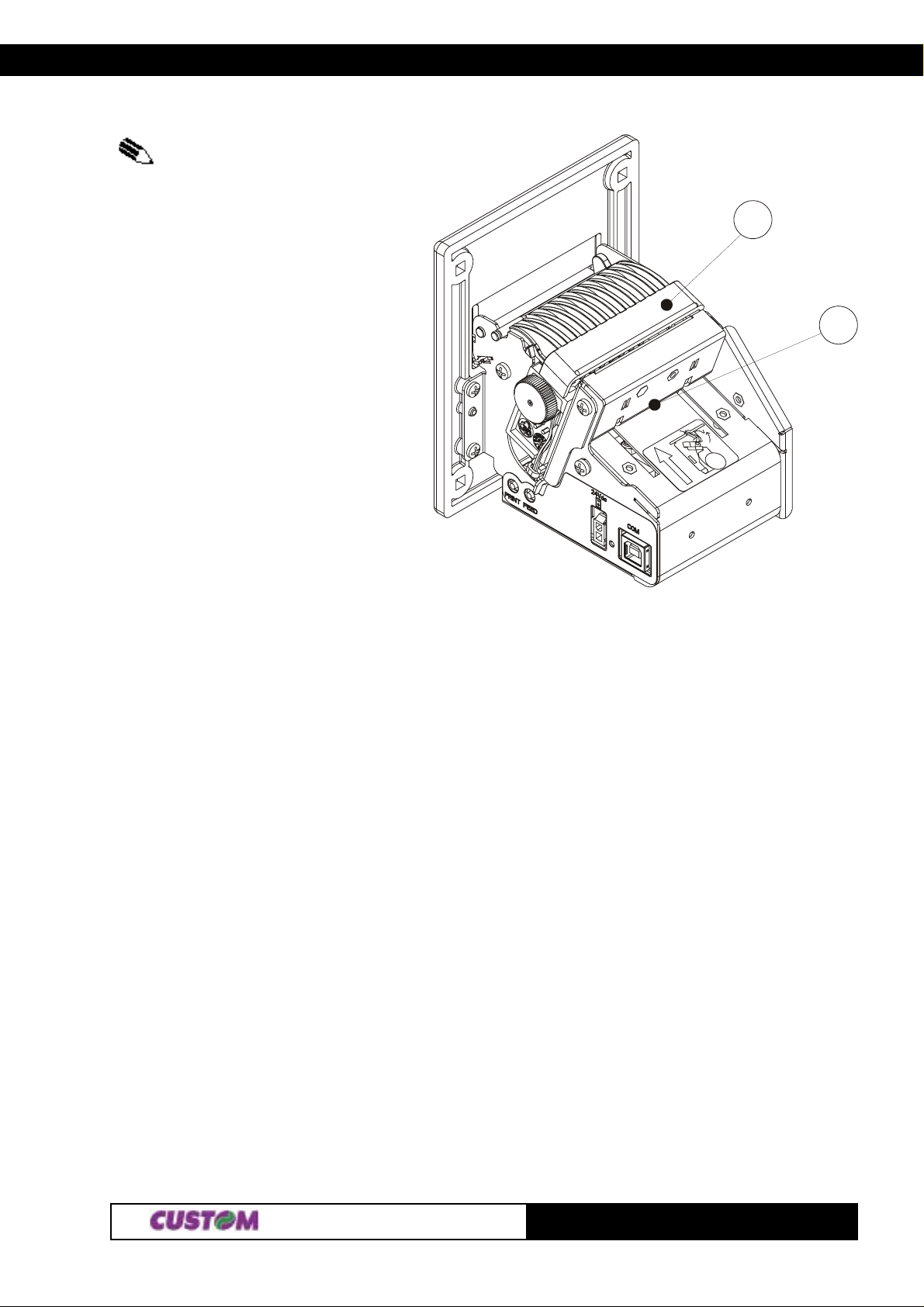
D. Back view
(4)
The back view is the same for all models available.
(4)
1- Paper input
2- Inspection cover for paper outlet
2
1
TG1260/2460
Page 6

Blank page
TG1260/2460
Page 7

TABLE OF CONTENTS
INTRODUCTION
MANUAL ORGANIZA TION ............................................................................................................................... 1
SYMBOLS USED IN THE MANUAL................................................................................................................. 1
GENERAL SAFETY INFORMA TION ................................................................................................................ 1
UNPACKING THE PRINTER ............................................................................................................................ 2
PRINTER DESCRIPTION ................................................................................................................................. 2
MAIN APPLICATIONS ...................................................................................................................................... 2
1. INST ALLA TION AND OPERA TION
1.1 CONNECTIONS ..................................................................................................................................... 1-1
1.1.1 Power supply TG1260 .................................................................................................................... 1-1
1.1.2 Power supply TG2460 .................................................................................................................... 1-1
1.1.3 USB connector ............................................................................................................................... 1-2
1.1.3 RS232 serial connector .................................................................................................................. 1-2
1.1.5 Connection printer-PC .................................................................................................................... 1-3
1.2 SETUP ................................................................................................................................................... 1-3
1.3 AUTOTEST............................................................................................................................................. 1-4
1.4 MAINTENANCE....................................................................................................................................... 1-5
1.4.1 Changing the paper roll ................................................................................................................... 1-5
1.4.2 Notes for installation and using the printer in the upside down position ........................................... 1-6
2. PRINTER FUNCTIONS
2.1 CONTROL CHARACTERS ...................................................................................................................... 2-1
2.1.1 ESC/POS Emulation ...................................................................................................................... 2-1
2.1.2 CUSTOM Emulation......................................................................................................................2-29
2.1.3 CBM iDP560RS Emulation............................................................................................................2-49
3. TECHNICAL SPECIFICA TIONS
3.1 TECHNICAL SPECIFICA TIONS ............................................................................................................... 3-1
3.2 DIMENSIONS.......................................................................................................................................... 3-3
3.2.1 TG2460-U-A .................................................................................................................................... 3-3
3.2.2 TG2460-U-N .................................................................................................................................... 3-3
3.2.3 TG2460-U-M.................................................................................................................................... 3-4
4. CHARACTER SET
4.1 CHARACTER SET .................................................................................................................................. 4-1
APPENDIX A - ACCESSORIES AND SPARE PARTS
A.1 ACCESSORIES...................................................................................................................................... A-1
A.1.1 Power supply.................................................................................................................................. A-1
A.1.1.1 Power supply for TG2460 ............................................................................................................ A-1
A.1.1.2 Power supply for TG1260 ............................................................................................................ A-2
A.1.2 Adjust able paper holder support kit .................................................................................................A-3
A.1.3 Paper dispenser unit..................................................................................................................... A-12
A.2 SPARE PARTS..................................................................................................................................... A-13
i
TG2460
Page 8

TABLE OF CONTENTS
Blank page
TG2460
ii
Page 9
INTRODUCTION
MANUAL ORGANIZA TION
In addition to the Introduction which contains information regarding the symbols used in the manual, general
safety information, instructions for unpacking the printer and a brief description and main characteristics of the
machine, this manual is divided into the following chapters:
Chapter 1: Contains the information required for correct printer installation and use
Chapter 2: Contains a description of printer controls
Chapter 3: Contains printer technical data
Chapter 4: Contains the character sets (fonts) used by the printer
Appendix: Contains the printer accessories and spare parts description
SYMBOLS USED IN THE MANUAL
NOTE
Gives important information or suggestions for printer use.
WARNING
Information indicated by this symbol must be followed carefully to avoid damaging the printer.
DANGER
Information indicated by this symbol must be followed carefully to avoid damage or operator injury .
GENERAL SAFETY INFORMA TIONS
• Read and retain the instructions which follow .
• Before cleaning the printer, be sure to pull out the electrical cable.
• Use a damp cloth to clean the printer. Do not use liquid or spray product s.
• Do not operate the printer near water.
• When positioning the printer, make sure its cables will not be damaged.
• Use the type of electrical power supply indicated on the printer label. If uncertain, contact your dealer .
• Do not insert objects inside the printer as this could cause short-circuiting or damage components that
could jeopardize printer functioning.
• Do not spill liquids onto the machine.
• Do not carry out repairs on the machine yourself, except for the normal maintenance operations given in
the user manual.
• Unplug the printer from the electrical mains and call a specialized repairman if any of the following
conditions should arise:
A. the power supply connector is damaged
B. liquid has spilled into the printer
C. the printer has been exposed to rain or water
D. the printer is not functioning normally despite the fact that all instructions given in the user
manual have been followed
E. the printer has been dropped and the cover is damaged
F. printer performance is noticeably reduced
G . the printer is not working
1
TG2460
Page 10
INTRODUCTION
UNP ACKING THE PRINTER
Remove the printer from the carton, taking care not to damage the packing materials which should be retained
for future shipping/moving.
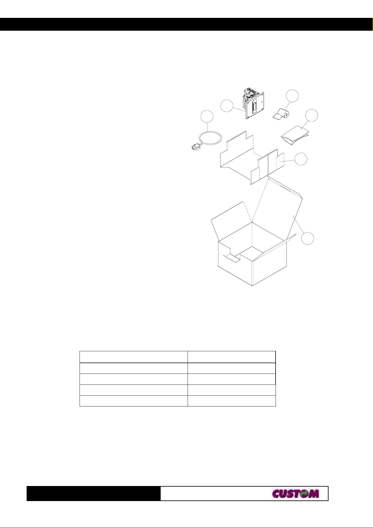
Make sure all components listed below are present and not damaged. If any part is missing and/or damaged,
contact customer service.
1. Box
2. Foam packing shell
3. Print
4. Paper roll
5. Manual (or CD-rom)
6. Electrical supply cable
3
6
4
5
2
PRINTER DESCRIPTION
Ultra compact thermal printer (only 9cm deep)
for dispensing 60 mm tickets width, easy to
install (4 fastening holes and ticket presentation
to user incorporated). Thanks to the exclusive
anti-paper-jam system, the ticket will always
be promptly dispensed to the user. Thanks to an
innovative type of paper roll holding bracket,
it is possible to accommodate up to 80 mm external
diameter paper rolls, adapt the printer to the mechanical
space requirements necessitated by the application
(3 positions: upper, lower and rear) and manage the
near paper end signal. It is equipped with a 204 dpi thermal
print mechanism; it has the serial RS232 interface and the
USB interface and it’s also available a version equipped with
fireproof plastic or metal front panel, with or without autocutter .
• When the “PRINT” key is pressed during printer power up, it prints the graphic test.
• When the “FEED” key is pressed during printer power up, it prints the font test.
• When both the “PRINT” and the “FEED” keys are pressed during printer power up, it prints the SETUP report.
Pressing the “PRINT” key it’s possible to change the parameters value and to print the parameter current
value; pressing the “FEED” key it’s possible to pass to the next parameter till the end of the SETUP.
• The green Status LED displays a printer hardware error status and the winnings. The check is carried out“on
line”, i.e. in the event of a malfunctioning, the LED will starts flashing as follows:
1
(Fig. 1)
DELSUTATSNOITPIRCSED
FFOsyawlAFFOretnirP
NOsyawlAstluafon–NOretnirP
)doirepgnolarofno(gnihsalfwolSdesiarrevocgnitliT
)doireptrohsarofno(gnihsalfwolSegasseMtuOrepaP
MAIN APPLICATIONS
This printer is the ideal solution for :
• kiosks (internet, public offices, bookings, bank transactions); • instant lotteries;
• self-service; • instruments;
• ticket dispensing (public/private transport, automatic payments); • gaming machines;
• parking lots; • vending machines;
• queue management systems.
TG2460
2
Page 11
1. INSTALLATION AND OPERATION
1.1 CONNECTIONS
(Fig.1.1)
1.1.1 Power supply (1260)
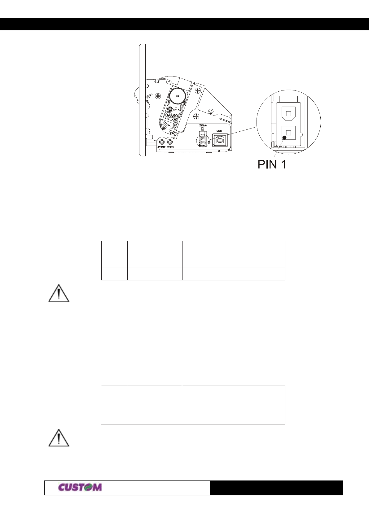
Every printer available is equipped with a 2 pin male molex connector serie 5569, for the power supply . The
signals on the pins of the feed connector are as follows:
Model no. type : Header : 90° Molex serie 5569 (no. 39-30-1020)
Housing: Molex serie 5557 (no. 39-01-3022)
NIPLANGISNOITPIRCSED
1
2
WARNING:
Be sure to observe the correct polarity for the power supply .
1.1.2 Power supply (2460)
Every printer available is equipped with a 2 pin male molex connector serie 5569, for the power supply . The
signals on the pins of the feed connector are as follows:
Model no. type : Header : 90° Molex serie 5569 (no. 39-30-1020)
Housing: Molex serie 5557 (no. 39-01-3022)
NIPLANGISNOITPIRCSED
1
V 21+REWOP
V42+REWOP
DNGDNUORGLANGIS
(Tab.1.1)
(Tab.1.2)
2
WARNING:
Be sure to observe the correct polarity for the power supply .
DNGDNUORGLANGIS
11-
TG1260/2460
Page 12
1. INSTALLATION AND OPERATION
1.1.3 USB connector
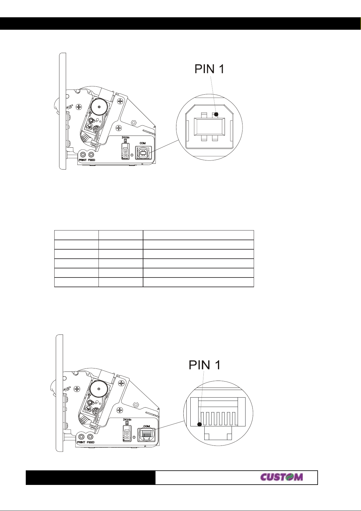
The printer with USB interface complies to USB 1.1 specifications that is:
• Communication speed equal to 12 Mbit/sec.
• Type of connector “Receptacle series B”.
(Fig.1.2)
The signals on the pins of the USB connector are as follows:
NIPLANGISNOITPIRCSED
1SUBV.C.N
2-D-ataD
3+D+ataD
4DNGlangisdnuorG
LLEHSDLEIHSgnidleihselbaC
(Tab.1.3)
1.1.4 RS232 serial connector
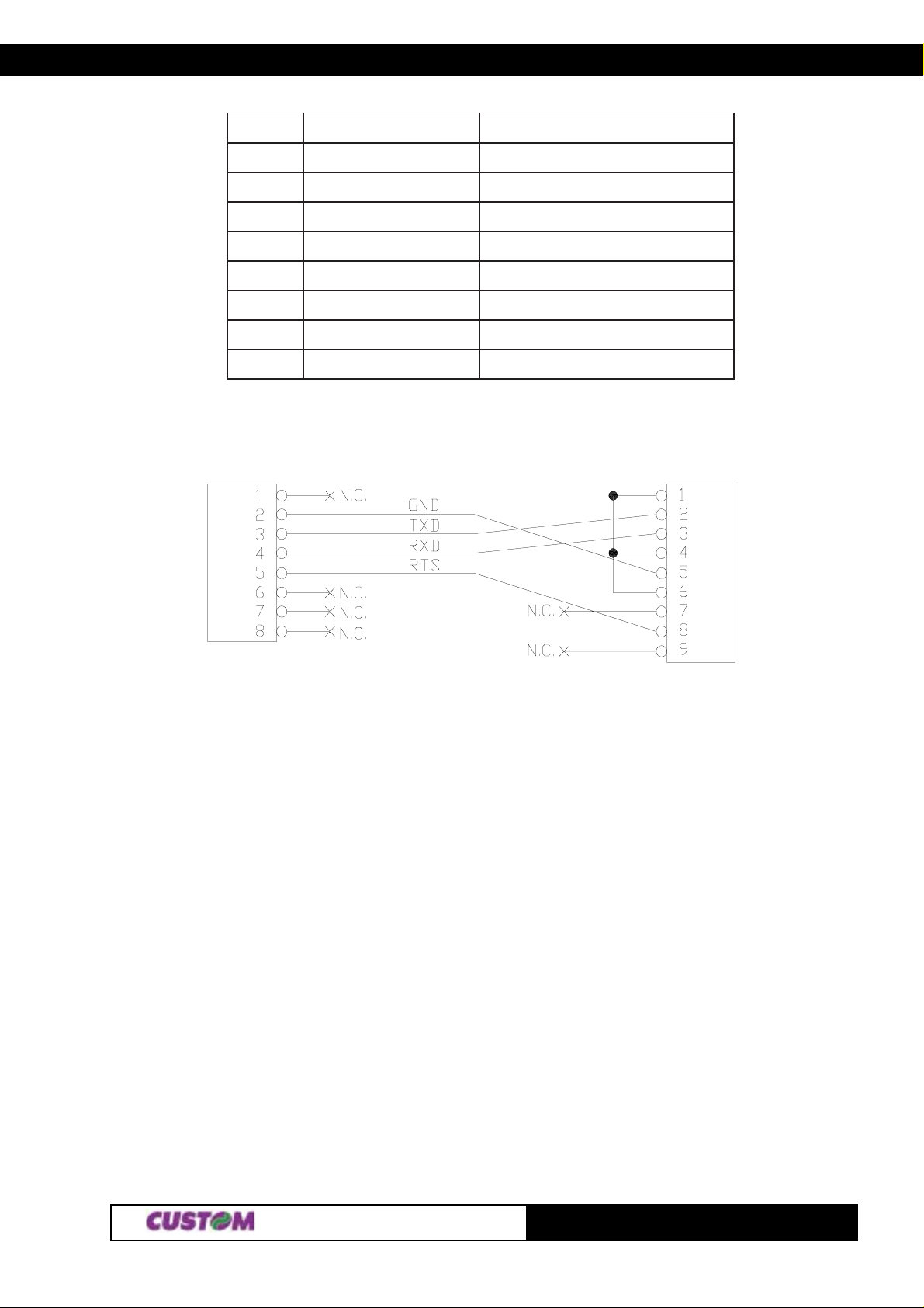
The printer with serial RS232 interface is equipped with RJ45 connector. In the following t able are described
the signals on the RS232 connector pins:
(Fig.1.3)
TG1260/2460
21-
Page 13
1. INSTALLATION AND OPERATION
NIPLANGISNOITPIRCSED
1 .C.NdetcennoCtoN
2 DNGlangisdnuorG
3 DXTnoissimsnartataD
4 DXRnoitpecerataD
5 STRdnesotydaeR
6 .C.NdetcennoCtoN
7 .C.NdetcennoCtoN
8 .C.NdetcennoCtoN
(Tab.1.4)
1.1.5 Connection Printer-PC
The diagrams below show a sample connection between printer and Personal Computer using a 8 pin male
RJ45 connector by printer side and a 9 pin female connector by a PC side.
(Fig.1.4)
Printer side PC side
1.2 SETUP
The printer enables the configuration of the printer default parameters (see fig. 1.4) pressing both the “PRINT”
and the “FEED” keys during the printer power up. The parameters affected during configuration are:
• Printer emulation: ESC/POSTM D, CUSTOM DPT24, CUSTOM DPT42 o CBM iDP560RS.
• Baud Rate: 115200, 57600, 38400, 19200D, 9600, 4800, 2400, 1200.
• Data Lenght: 7, 8D bits/chr.
• Parity: NoneD, even or odd.
• Handshaking: XON/XOFFD or Hardware.
• Autofeed: CR disabledD o CR enabled.
• USB Address
• USB Monitor
(2)
: 0D, 1, 2, 3, 4, 5, 6, 7, 8, 9.
(2)
: DisabledD or enabled.
• Panel key: EnabledD or Disabled.
• Print mode: NormalD o Reverse.
• Font type:
“ESC/POS“ emulation:
Chars / line: A=32 / B=42 col.D or A=42 / B=56 col.
“DPT24” emulation:
Font type : Font AD or Font B.
“DPT42” emulation:
Font type : Font AD or Font B.
“CBM iDP560RS“ emulation:
Font dimensions: 1 1x24D 40 col. or 18x24 24 col.
31-
TG1260/2460
Page 14
1. INSTALLATION AND OPERATION
• Speed/Quality: NormalD, Low.
• Offline
• Print density: NormalD, Dark, Very Dark, Light, V ery Light.
Notes: The parameters indicates with a D symbol are the default values.
(1)
(2)
The settings made are saved on the EEPROM (non volatile memory).
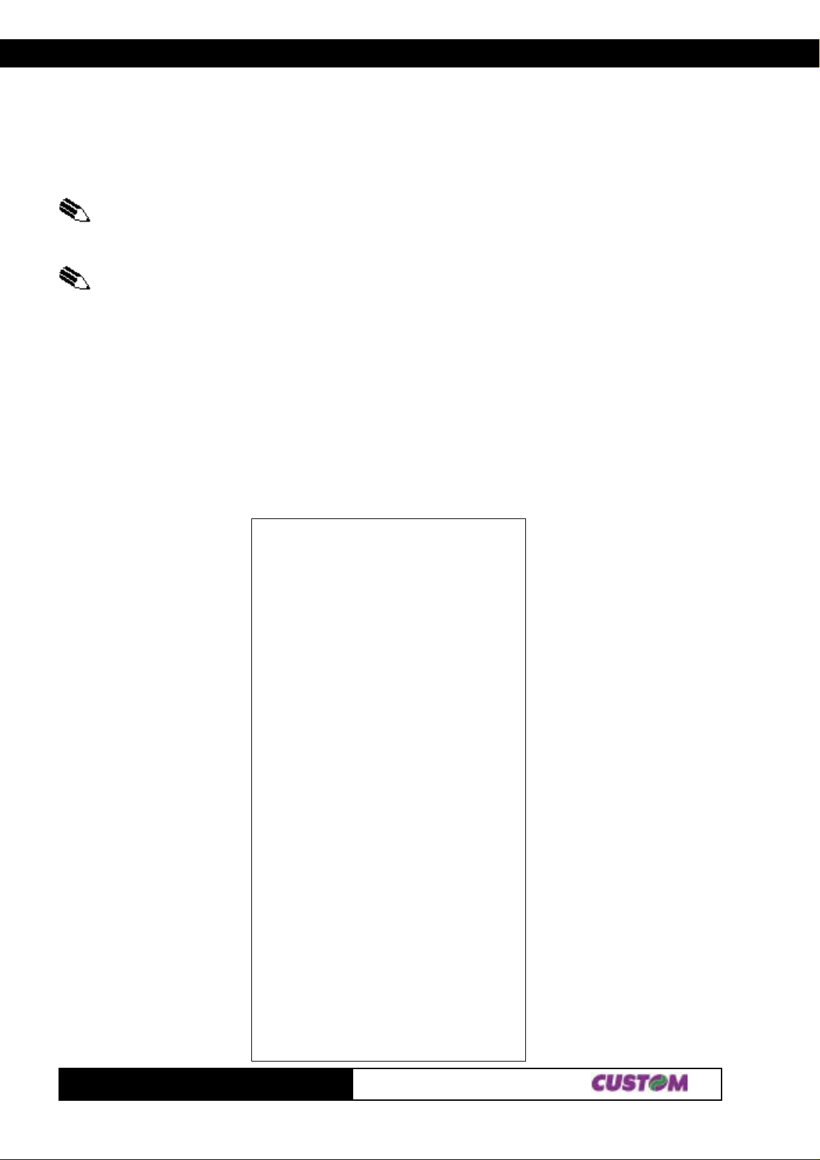
During the setup routine the printer prints out the setup report and will remain in standby until another key is
pressed or characters are received through the printer communication port. Af ter this, each time the “PRINT”
key is pressed, the parameter is modified and its current value is printed. Once the required value has been
obtained, press the “FEED” key to proceed to the next parameter , and so on. Once all the p arameters have
been run through, the printing of a message signals the end of the setting procedure.
1.3 AUTOTEST
T o run the autotest, press the “FEED” key while switching on the printer. During the running of the autotest, the
character fonts and logos stored inside the printer are printed.
(1)
: DisabledD, Enabled.
NOTE: Using this parameter , it is possible to select whether the Busy signal is activated
when the printer is both in Off Line status and the buffer is full, or only if the reception
buffer is full.
NOTE: These parameters are shown only for the USB interface models.
* PRINTER SETUP *
PROGRAM MEMORY..................OK
PRINTER BUFFER......................OK
CUTTER......................................OK
HEAD VOL T AGE............ [V] = 24,00
HEAD TEMPERATURE [°C ] = 32,5
Printer Emul. : ESC/POS (TM)
Baud Rate : 9600 bps
Data length : 8 bits/chr
Parity : None
Handshaking : Xon/Xoff
Autofeed : CR disabled
USB Address : 0
USB Monitor : Disabled
Panel key : Enabled
Print Mode : Normal
Chars / line : A=32/B=42 col
Speed/Quality : Normal
Offline : Disabled
Print Density : Normal
(Fig.1.5)
TG1260/2460
[PRINT] key to enter setup
[FEED] key to skip setup
41-
Page 15
1. INSTALLATION AND OPERATION
1.4 MAINTENANCE
1.4.1 Changing the paper roll
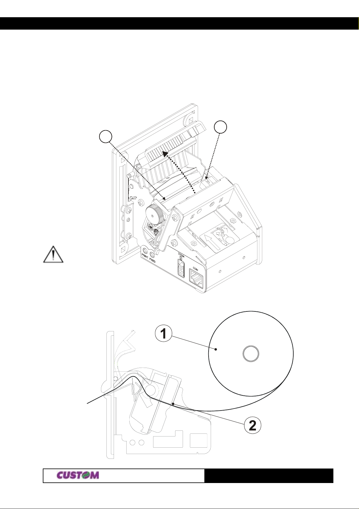
Every time you change the paper, referred to fig.1.5, need to check as follows :
• Lift the wicket relative to paper roll compartment, and check that there are no scraps of paper at the area
indicated with a) letter near the printing head. If there are, remove the scraps before proceeding with any other
operation.
b
a
(Fig.1.6)
WARNING: Periodically remove accumulated paper dust from the drag paper roll and the area
around the paper outfeed sensor (see fig. 1.5 in the he points indicated with b letter).
(Fig.1.7)
51-
TG1260/2460
Page 16
1. INSTALLATION AND OPERATION
To clean, do not use harsh chemical solvents; the use of a soft, alcohol-moistened
cloth is recommended.
T o change the paper roll in the printer , proceed as follows:
1) Position the paper roll (1), so that it rotates in the direction shown in fig.1.6;
2) Insert the end of the paper roll in the print mechanism (2)and wait until the roll loads automatically;
3) Remove the ticket from the mouth paper output;
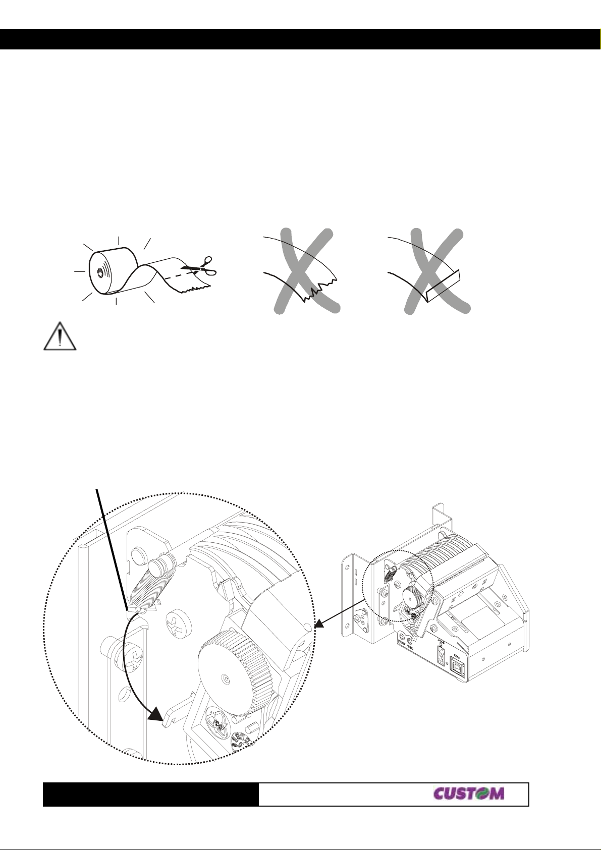
WARNING
Before inserting the paper , ensure that it is cut evenly .
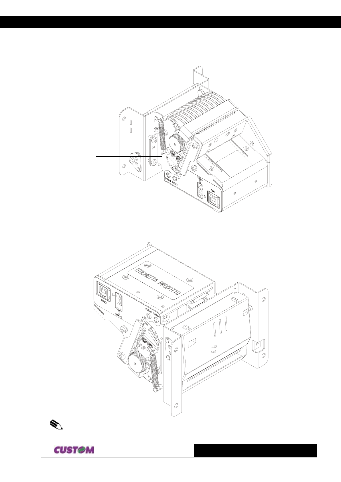
1.4.2 Notes for installation and using the printer in the upside down position
T o inst all the printer in the upside down position proceed as follows :
Release the spring
from this side
(Fig.1.8)
(Fig.1.9)
TG1260/2460
61-
Page 17
1. INSTALLATION AND OPERATION
1) Release the spring as indicated in fig. 1.8 and placed it in the new position as indicated in fig. 1.9;
(Fig.1.10)
Hook the spring
in this position
2) The printer is ready to be installed in the upside down position.
(Fig.1.11)
(3)
NOTE: The operations described are valid for all models.
71-
TG1260/2460
Page 18
2. PRINTER FUNCTIONS
2.1 CONTROL CHARACTERS
2.1.1 ESC/POS Emulation
The following table lists all the commands for the management of the ESC/POS™ Emulation. The commands
can be transmitted to the printer at any moment, but they will only be carried out when the commands
previously sent have been executed. There are no commands with priority status; all the commands are
carried out when the circular buffer is feed to do so.
(Tab.2.1)
.moCXEH.moCIICSAnoitpircseD
80$SBretcarahcenofokcabgnivoM
90$THsbatlatnoziroH
A0$FLdeefenildnatnirP
D0$RCdeefenildn
n40$01$nTOEELDnoissimsnartsutatsemit-laeR
81$NACatadtnirplecnaC
n02$B1$nPSCSEgnicapsedis-thgirretcarahc
n12$B1$n!CSEedomtnirpteS
HnLn42$B1$HnLn$CSEnoitisopetulosbateS
kd...1dHnLnmA2$B1$kd...1dHnLnm*CSEedomegami
nD2$B1$n-CSEffo/noedomenilrednunruT
03$B1$0CSEgnicapsenilhcni-8/1tceleS
23$B1$2CSEgnicapsenilhcni-6/1tc
n33$B1$n3CSEstinumuminimgnisugnicapsenilteS
n43$B1$n4CSEedomtpircsteser/teS
nD3$B1$n=CSEecivedtceleS
$@CSEretnirpezilaitinI
$nGCSEedomekirts-elbuodtceleS
$nVCSE°09ybdetatoredomtnirpteS
04$B1
00kn...1n44$B1$LUNkn...1nDCSEnoitisopbatlatnozirohteS
n54$B1$nECSEedomdlobtceleS
n74$B1
nA4$B1$nJCSErepapdeefdnatnirP
n25$B1$nRCSEtesretcarahclanoitanretnitceleS
n65$B1
HnLnC5$B1$HnLn\CSEnoitisoptnirpevitalerteS
n16$B1$naCSEnoitacifitsujtceleS
36$B1$n5cCSEsyeklenapelbasid/elbanE
n53$
n46$B1$ndCSEsenilnrepapdeefdnatnirP
96$B1$iCSEtuclatoT
n47$B1$ntCSEelbatedoc
67$B1$vCSEsutatsretnirptimsnarT
87$B1$xCSEedomytilauq/deepstceleS
nB7$B1$n{CSEgnitnirpretcarah
LyHyLxHxnAF$B1$LyHyLxHxn·CSEknabcihpargtnirP
HnLnFF$B1$HnLn}{CSEhsalfniyromemdnaogol
43$0C$C1$4}{SFkcabgnivomrepapcitamotuadnatuclatoT
n12$D1$n!SGezisretcarahctceleS
A3$D1$:SGnoitinifedor
COMMAND T ABLE
atnirP
teS
tibteS
eleS
retcarahctceleS
cnwod-edispulecnac/teS
evieceR
camfodne/gnitratsteS
2-1
TG1260/2460
Page 19
2. PRINTER FUNCTIONS
.moCXEH.moCIICSAnoitpircseD
n24$D1$nBSGffo/nognitnirpesreverkcalb/etihwnruT
mn03$34$D1$mn0CSGedomtnirpretnuoc
rnHbLbHaLa13$34$D1$rnHbLbHaLa1CSG)A(edomtnuoctceleS
HnLn23$34$D1$HnLn2CSGretnuoctceleS
4$D1$
n84$D1$nHSGsretcarahcIRHfonoitisopgnitnirptcel
n94$D1$nISGDIretnirptimsnarT
HnLnC4$D1$HnLnLSGnigramtfelteS
yx05$D1$yxPSGstinunoitomlacitrevdnalatnozirohte
HnLn75$D1$HnLnWSGhtdiwaeragnitnirpteS
mtrE5$D1$mtr^SGorcametucexE
36$D1$cSGretnuoctnirP
n66$D1$nfSGsretcarahcIR
n86$D1$nhSGedocrabfothgiehtceleS
00mB6$D1$LUNmkSGedocrabtnirP
n27$D1$nrSGsutatstimsnarT
n77$D1$nw
nE7$D1$n~SGtpircsbus/tpircsrepusteS
nC7$D1$n|SGytisnedgnitn
B3$bsB3$asB3$3
B3$csB3$rsB3$ns
;cs
SG edocrab)fo)noitacifingam(ezislatnozirohtceleS
;rs;ns;bs;as;CSG
tceleS
eS
S
irpteS
)B(edomtnuoctceleS
HroftnoftceleS
NOTE: in “Note” column where the model is not specified, the command is valid for all models.
The following pages provide a more detailed description of each command.
80$
[Name] Moving back of one character
[Format] ASCII BS
Hex 08
Decimal 8
[Description] Moves print position to previous character.
[Notes] This command can put two characters at the same position.
[Default]
[Reference]
[Example]
90$
[Name] Horizontal tabs
[Format] ASCII HT
Hex 09
Decimal 9
[Description] Moves the print position to the next horizontal tab position.
[Notes] • This command is ignored if the next horizontal tab position has not been set.
• If the next horizontal tab is outside the print area, the printer will print the entire
contents of the print buffer , then proceed with the processing of the horizont al t abs from
the beginning of the following line.
• The horizontal tabs are set through the command $1B $44.
TG1260/2460
2-2
Page 20

2. PRINTER FUNCTIONS
[Default]
[Reference] $1B $44
[Example]
A0$
[Name] Print and line feed
[Format] ASCII LF
Hex 0A
Decimal 10
[Description] Prints the data in the buffer and feeds one line, based on the current line spacing.
[Notes] • This command sets the print position at the beginning of the line.
[Default]
[Reference] $1B $32, $1B $33
[Example]
D0$
[Name] Print and line feed
[Format] ASCII CR
Hex 0D
Decimal 13
[Description] When autofeed is $0D enabled, this command functions in the same way as $0A,
otherwise it is ignored.
[Notes] • This command sets the print position at the beginning of the line.
[Default] See autofeed parameter on Setup.
[Reference] $0A
[Example]
n40$01$
[Name] Transmission of status in real time
[Format] ASCII DLE EOT n
Hex 10 04 n
Decimal 16 4 n
[Range] 1 ≤ n ≤ 4, n =17, 20 ≤ n ≤ 21
[Description] Transmits in real time the selected status of the printer specified by n according to the
following parameters:
n = 1 transmit printer status
n = 2 transmit off-line status
n = 3 transmit error status
n = 4 transmit paper roll sensor status
n = 17 transmit paper status
n = 20 transmit Full Status
n = 21 transmit printer ID ($6D )
[Notes] • This command is executed even when the reception buffer is full.
The status is transmitted whenever the data sequence $10 $04 n is received.
[Default]
[Reference]
[Example]
n=1: Printer status
2-3
TG1260/2460
Page 21
2. PRINTER FUNCTIONS
tiBnO/ffOxeHlamiceDnuFnoitc
0
1- - - DEVRESER..
2- - - DEVRESER.
3
4
5
6- - - DEVRESER.
7- - - DEVR
n=2: Off-line status
-- - DEVRESER.
ffO000 .enil-nO
nO808 .enil-ffO
-- - DEVRESER.
-- - DEVRESER.
ESER.
tiB
0
1- - - .DEVRESER
2
3
4- - - .DEVRESER
5
6
7- - - .DEVRESER
nO/ffOxeHlamiceDnuFnoitc
-- - .DEVRESER
ffO000 .)majrepapon(nwoddaehtnirP
nO404 .)majrepap(pudaehtnirP
ffO000 .
nO808 .nottubDEEFybdefgniebsirepaP
ffO000 .potsdnerepapoN
nO0223.dnerepapo
ffO000 rorreoN
nO0446rorrE
n=3: Error status
tiB
0
1
2
3
4
5
6
7
nO/ffOxeHlamiceDnuFnoitc
-- - .DEVRESER
-- - .DEVRESER
-- - .DEVRESER
ffO000 *.rorrerettucotuaoN
nO808 *.rorrerettucotuA
-- - ..DEV
ffO000 .rorreelbisreverrioN
nO0223.rorreelbisreverrI
ffO000 .rorreelbarevocer-otuaoN
nO0464 .rorreelbarevocer-otu
-- - .DEVRESER
nottubDEEFybdefgniebtonsirepaP
teudspotsgnitnirP
RESER
A
TG1260/2460
2-4
Page 22
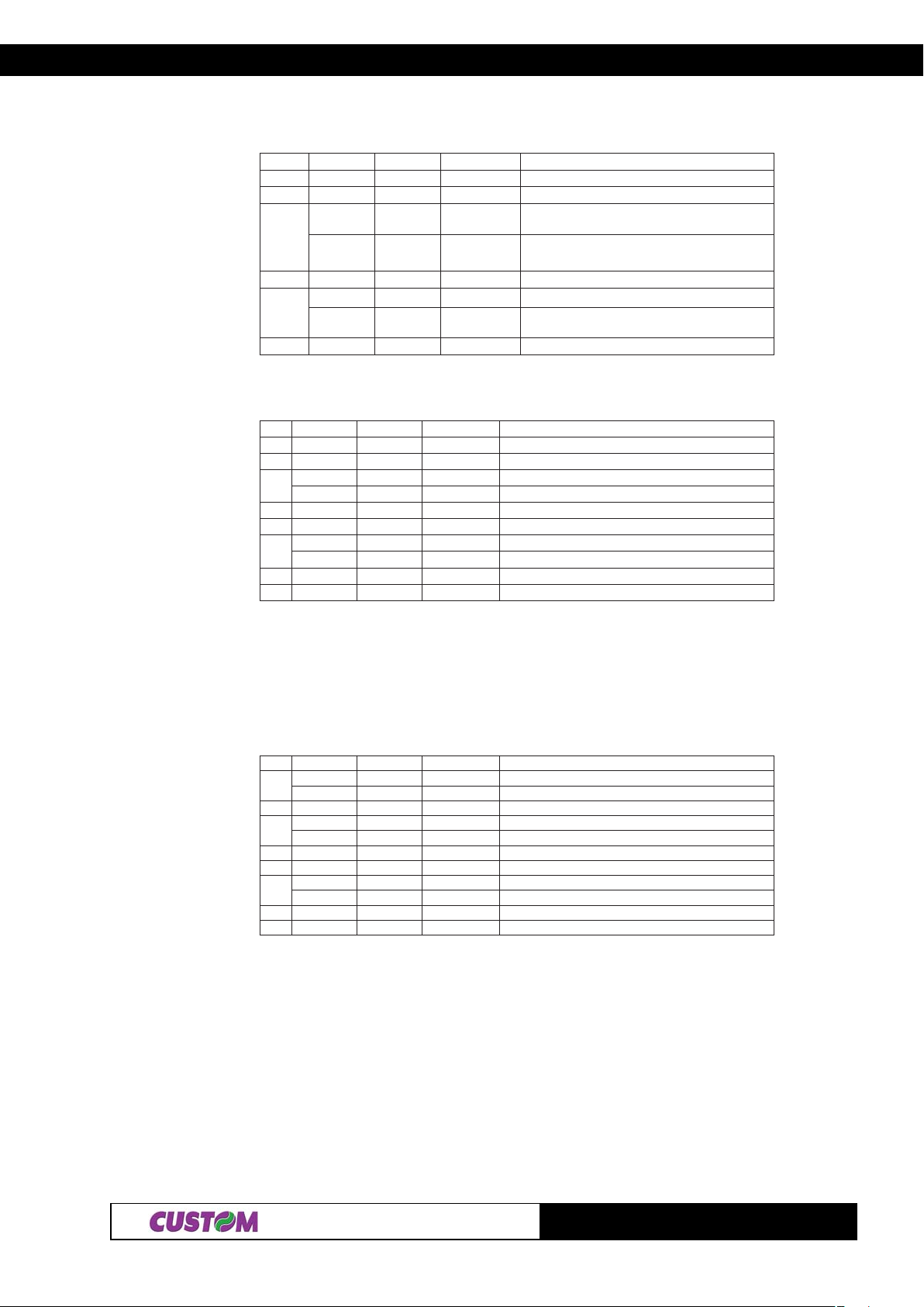
2. PRINTER FUNCTIONS
n=4: Paper roll sensor status
tiBnO/ffOxeHlamiceDnuFnoitc
0- - - DEVRESER
1- - - DEVRESER
ffO000
3,2
4- - - DEVRESER
6,5
7- - - DEVRESER
n=17: Paper status
tiBnO/ffOxeHlamiceDnoitcnuF
0- - - DEVRESER
1- - - DEVRESER
2
3- - - DEVRESER
4- - - DEVRESER
5
6- - - .DEVRESER
7- - - DEVRESER
nO0C 21
ffO000 .rosnesdnerepapehtybdetcetedsirepaP
nO0669
ffO00 0 .gninnurtonrotoM
nO408 .gninnurrotoM
ffO000 .nirepaP
nO0223.dnerepaP
.rosnes
.dne
nerepaP
.rosnes
esdnerepaPrepapraenro
dnerepapraenehtybdetcetedsirepaP
tneserptonrosn
dnerepapehtybdetcetedsid
n=20: Full Status ( 6 bytes)
1° Byte = $10 (DLE)
2° Byte = $0F
3° Byte = Paper Status
tiBnO/ffOxeHlamiceDnoitcnuF
0
1- - - .DEVRESER
2
3- - - .DEVRESER
4- - - .DEVRESER
5
6- - - .DEVRESER
7- - - .DEVRESER
ffO000 .nirepaP
nO101 .dnerepaP
ffO00 0 .nirepaP
nO404 .dnerepapraeN
f
fO000 eerfrosnestuotekciT
nO0223ysubrosnestuotekciT
2-5
TG1260/2460
Page 23
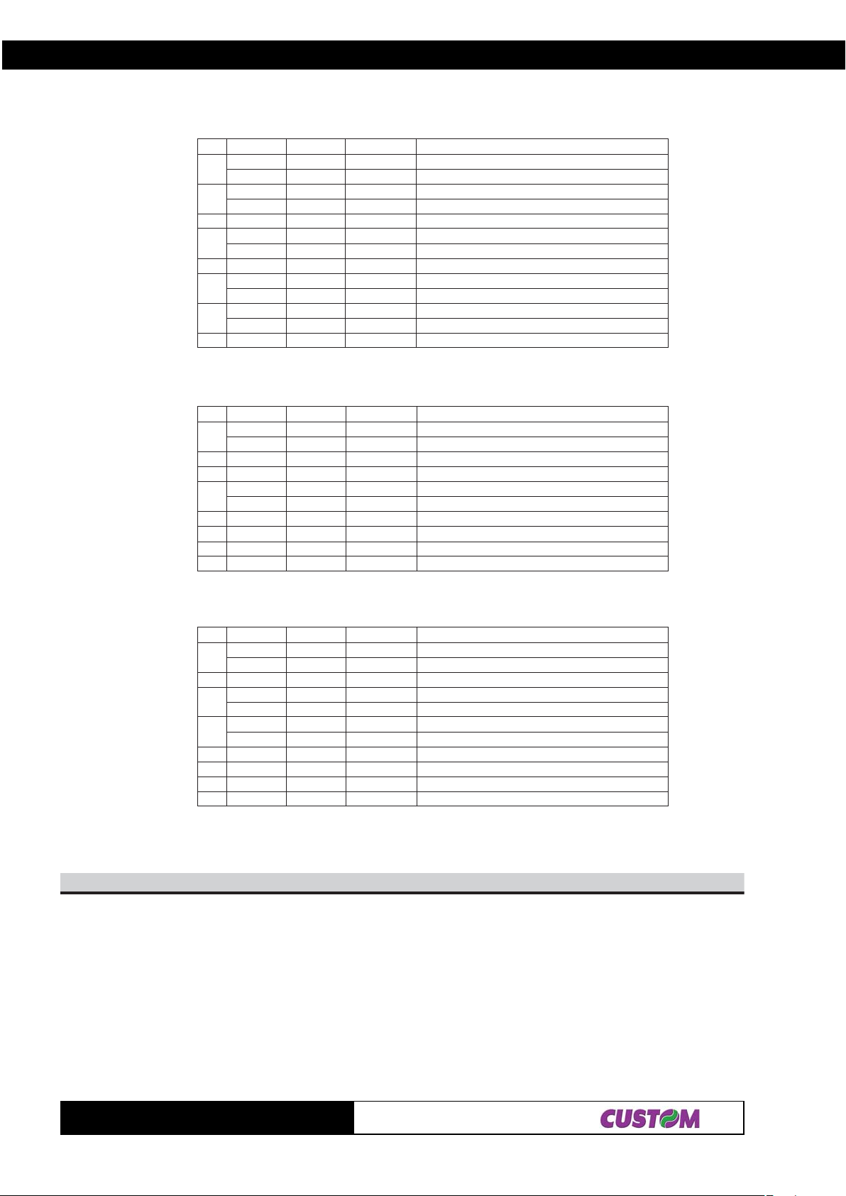
4° Byte = User Status
2. PRINTER FUNCTIONS
tiB
0
1
2- - -R DEVRESE
3
4
5
6
7- - -R DEVRESE
nO/ffOxeHlamiceDnoitcnuF
ffO000 .nwoddaehtnirP
nO101 .pudaehtnirP
ffO000 nwodrevoC.
nO202 .purevoC
ffO000 )nurrepap(g
nO808 )llitsdnatsrepap(gninnurtonrotoM
-- -RDEVRESE
ffO000 desserptonyekDEEF
nO0223desserpyekDEEF
ffO000 desser
nO0446desserpyekTNIRP
5° Byte = Recoverable Error Status
tiB
0
1- - -R DEVRESE
2- - -R DEVRESE
3
4
5
6- - -R DEVRESE
7- - -R DEVRESE
nO/ffOxeHlamiceDnoitcnuF
ffO000 .lamronerutarepmetdaehtnirP
nO101 .detaehrevodaehtnirP
ffO000 egnarn
nO808 egnarfotuoegatlovylppusrewoP
-- -RDEVRESE
-- -RDEVRESE
ninnurrotoM
ptonyekTNIRP
iegatlovylppusrewoP
6° Byte = Unrecoverable Error Status
tiB
0
1
2
3
4
5
6
7
nO/ffOxeHlamiceDnoitcnuF
ffO000 *rorrerettucotuaoN
nO101 *rorrerettucotuA
-- -RDEVRESE
ffO000 rorreMARoN
nO404 rorreMAR
ffO000 r
nO808 rorreMORPEE
-- -RDEVRESE
-- -RDEVRESE
-- -RDEVRESE
-- -RDEVRESE
orreMORPEEoN
Note(*): Only printer mudel with cutter
81$
[Name] Cancel print data buffer.
[Format] ASCII CAN
Hex 18
Decimal 24
[Description] Deletes all the print data in the current print buffer .
[Notes] This command sets the print position at the beginning of the line.
[Default]
[Reference]
[Example]
TG1260/2460
2-6
Page 24
2. PRINTER FUNCTIONS
n02$B1$
[Name] Set character right-side spacing
[Format] ASCII ESC SP n
Hex 1B 20 n
Decimal 27 32 n
[Range] 0 ≤ n ≤ 255
[Description] Sets spacing to right of character at [ n x horizontal or vertical motion units].
[Notes] • The spacing to the right of the character for double width mode is double that used for
normal mode. When the characters are enlarged, the spacing to the right of the
character is m (2 or 4) times the normal value.
• The horizontal and vertical motion units are specified by the command $1D $50.
Changing the horizontal or vertical motion does not affect the current right side spacing.
• The command $1D $50 can change the horizontal (and vertical) motion unit. However,
the value cannot be less than the minimum horizontal spacing amount.
• In standard mode, the horizontal motion unit is used.
• The maximum right side spacing is 255/200 inches.
[Default] n = 0
[Reference] $1D $50
[Example]
n12$B1$
[Name] Select print modes.
[Format] ASCII ESC ! n
Hex 1B 21 n
Decimal 27 33 n
[Range] 0 ≤ n ≤ 255
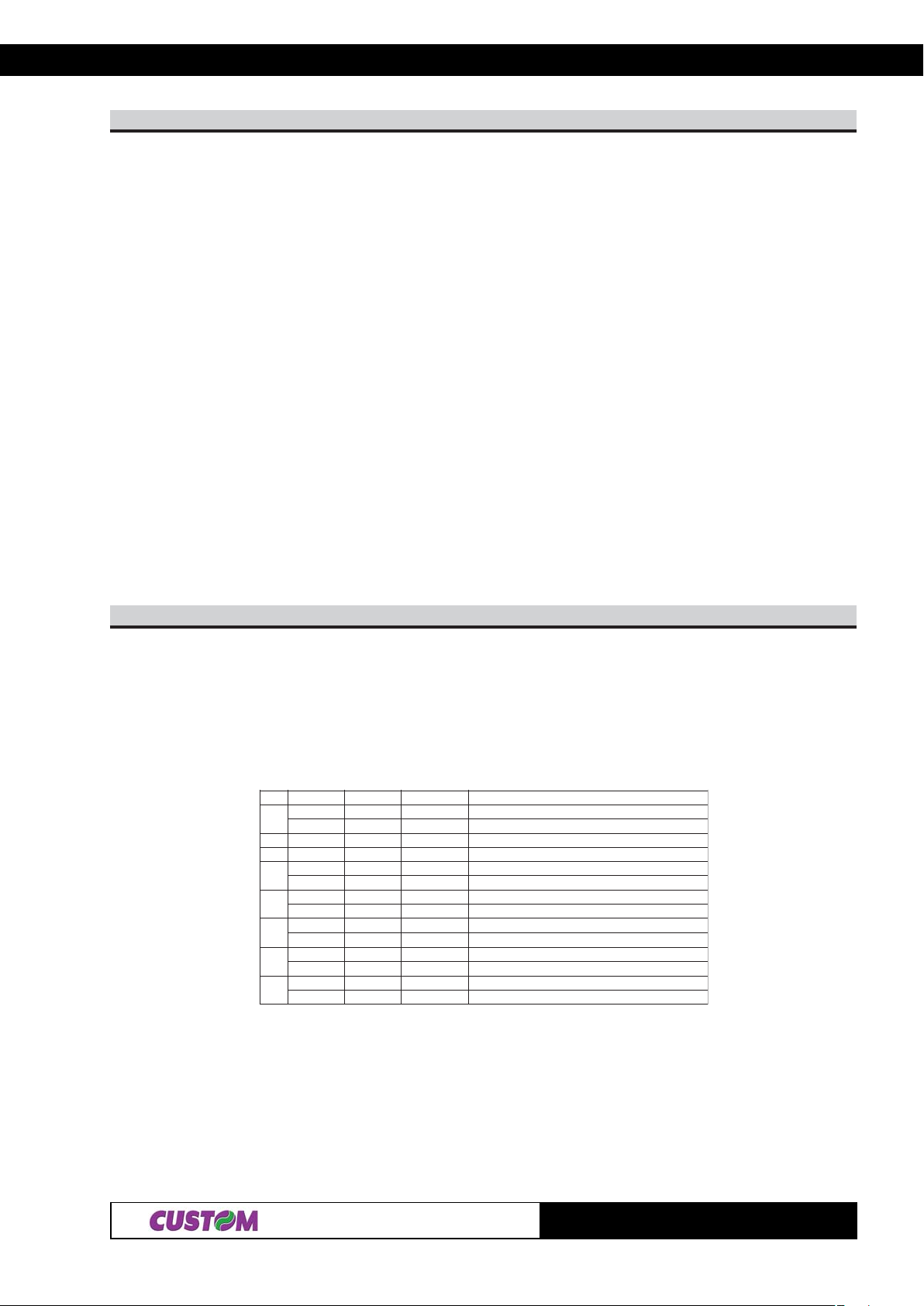
[Description] Selects the print mode using n (see following tables):
tiBnO/ffOxeHlamiceDnuFnoitc
0ffO000 .detcelesAtnofretcarahC
nO101 .detcelesBtnofretcarahC
1- - - .DEVRESER
2- - - .DEVRESER
3ffO000 .detcel
nO808 .detcelesedomdloB
4ffO000 .detcelestonedomthgiehelbuoD
nO0161.detcelesedomthgiehelbuoD
5ffO000 .detcel
nO0223.detcelesedomhtdiwelbuoD
6ffO000 .detcelestonedomtpircS
nO0446etcelesedomtpircSd.
7ffO000 .detce
nO08821.detcelesedomenilrednU
estonedomdloB
estonedomhtdiwelbuoD
lestonedomenilrednU
[Notes] • The printer can underline all the characters, but it cannot underline the space set by
commands $09, $1B $24, $1B $5C and 90° clockwise rotated characters.
• When the characters on the same line are enlarged to different heights, they are either
aligned at the baseline or topline (see $1D $7E).
• This command resets the left and right margin at the default value (see $1D $4C,
$1D $57).
• The command $1B $45 can also turn on/off bold mode. However, the setting of the
last received command is effective.
2-7
TG1260/2460
Page 25

2. PRINTER FUNCTIONS
• The command $1B $2D can also turn on/off underline mode. However, the setting of the
last received command is effective
• The command $1B $34 can also turn on/off script mode. However, the setting of the
last received command is effective.
• The command $1D $21 can select the character size. However,the setting of the last
received command is effective.
[Default] n = 0
[Reference] $1B $45, $1B $2D, $1B $34, $1D $21
[Example]
HnLn42$B1$
[Name] Set absolute print position
[Format] ASCII ESC $ nL nH
Hex 1B 24 nL nH
Decimal 27 36 nL nH
[Range] 0 ≤ nL ≤ 255
0 ≤ nH ≤ 255
[Description] Sets the distance from the beginning of the line to the position in which the subsequent
characters are to be printed.
The distance from the beginning of the line to the print position is [(nL + nH × 256) × (vertical or horizontal
motion unit)] inches.
[Notes] • Settings outside the specified printable area are ignored.
• The vertical and horizontal motion units are specified by $1D $50.
• The command $1D $50 can change the horizontal (and vertical) motion unit. However,
the value cannot be less than the minimum horizontal movement amount.
• In standard mode the horizontal motion unit (x) is used.
• If the setting is outside the printing area width, set absolute print position, but left or
right margin is set at default value.
[Default]
[Reference] $1B $5C, $1D $50
[Example]
kd...1dHnLnmA2$B1$
[Name] Select bit image mode.
[Format] ASCII ESC * m nL nH d1...dk
Hex 1B 2A m nL nH d1...dk
Decimal 27 42 m nL nH d1...dk
[Range] m = 0, 1, 32, 33
0 ≤ nL ≤ 255
0 ≤ nH ≤ 1
0 ≤ d ≤ 255
[Description] Selects a bit image-mode using m for the number of dots specified by nL and nH, as follows:
medoM
0ytisnedelgnisstod8876001652xHn+Ln
1ytisnedelbu
23ytisnedelgnisstod42420020013x)652xHn+Ln(
33ytisnedelbuodstod42420020023x)652xHn+Ln(
odstod8876002652xHn+Ln
stod°NIPDIPD)k(atad°N
TG1260/2460
noitceridlacitreV)1*(noitceridlatnoziroH
2-8
Page 26
2. PRINTER FUNCTIONS
[Notes] • The commands nL and nH indicate the number of horizontal dots in the graphic image.
The nL and nH indicate the number of dots of the bit image in the horizontal direction.
The number of dots is calculated by nL + nH × 256
• If the bit image data exceeds the number of dots to be printed on a line, the excess
data is ignored.
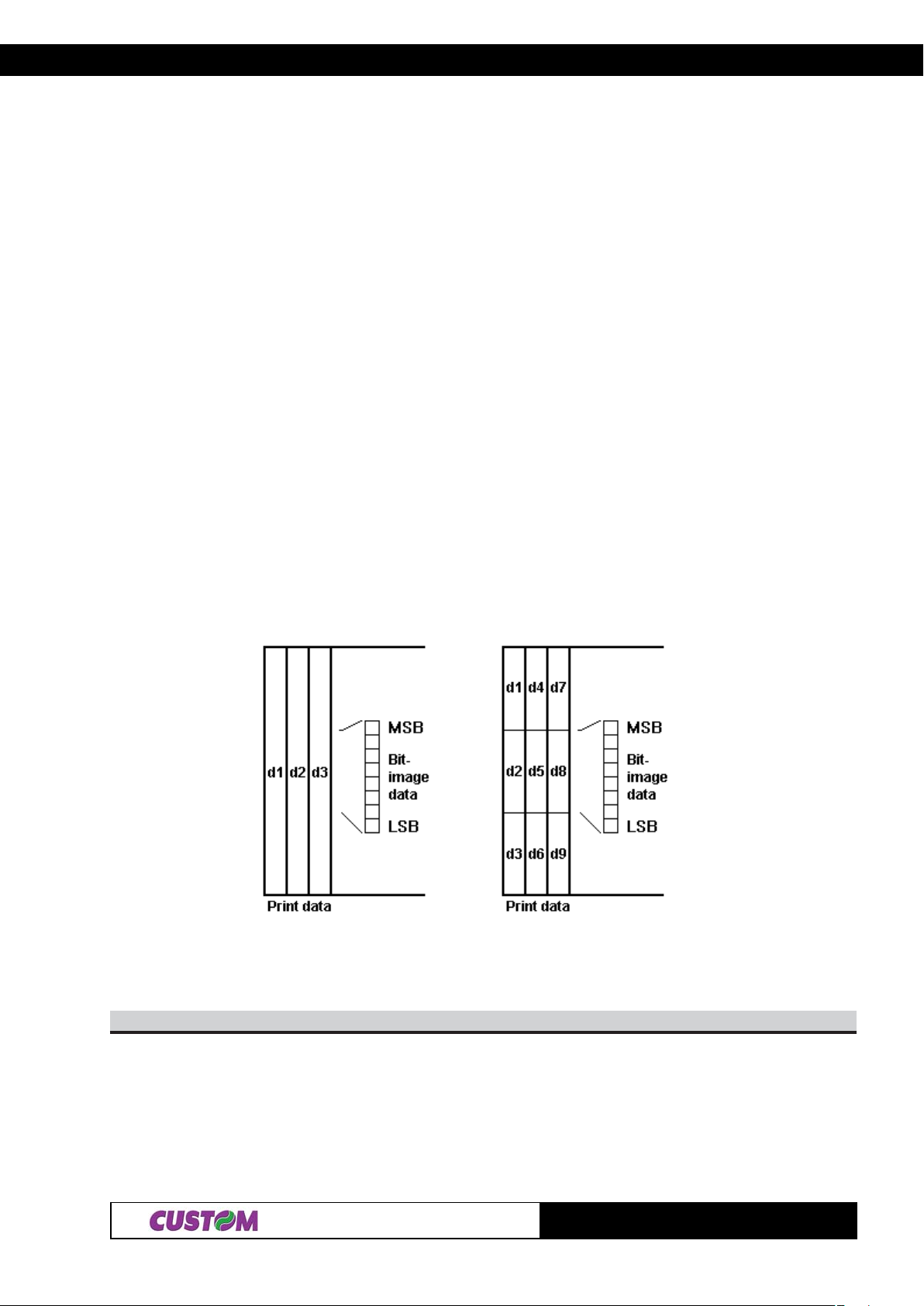
• d indicates the bit image data. Set a corresponding bit to 1 to print dot or to 0 not to
print dot.
• if the value of m is out of the specified range, nL and the data following are processed
as normal data.
• If the width of the printing area set by the commands $1D $4C and $1D $57 is less
than the width required by the data sent with the command $1B $2A , the excess data is
ignored.
• To print the bit image use commands $0A, $0D, $1B $4A or $1B $64.
• Af ter printing a bit image, the printer returns to normal dat a processing mode.
• This command is not affected by bold, double-strike and underline (etc.) print modes,
only by upside-down mode.
The relationship between the bit image and the dots to be printed is as follows:
8 dot image 24 dot image
[Default]
[Reference]
[Example]
nD2$B1$
[Name] Turn underline mode on/off.
[Format] ASCII ESC - n
Hex 1B 2D n
Decimal 27 45 n
[Range] 0 ≤ n ≤ 2, 48 ≤ n ≤ 50
[Description] Turns underline mode on or off, based on the following values of n:
n = 0, 48 Turns off underline mode
2-9
TG1260/2460
Page 27

2. PRINTER FUNCTIONS
n = 1. 49 Turns on underline mode (1-dot thick)
n = 2. 50 Turns on underline mode (2-dot thick)
[Notes] • The printer can underline all characters but cannot underline the space set by $09 and
right-side character spacing.
• The printer cannot underline 90° clockwise rotated characters and white/black inverted
characters.
• When underline mode is turned off by setting the value of n at 0 or 48, the following
data is not underlined.
• Underline mode can also be turned on or off by using $1B $21.Note, however , that the
last command received is effective.
[Default] n=0
[Reference] $1B $21
[Example]
03$B1$
[Name] Select 1/8-inch line spacing.
[Format] ASCII ESC 0
Hex 1B 30
Decimal 27 48
[Description] Selects 1/8-inch line spacing.
[Notes]
[Default]
[Reference] $1B $32, $1B $33
[Example]
23$B1$
[Name] Set line spacing at 1/6 inch.
[Format] ASCII ESC 2
Hex 1B 32
Decimal 27 50
[Description] Selects 1/6 inch line spacing.
[Notes]
[Default]
[Reference] $1B $30, $1B $33
[Example]
n33$B1$
[Name] Set line spacing.
[Format] ASCII ESC 3 n
Hex 1B 33 n
Decimal 27 51 n
[Range] 0 ≤ n ≤ 255
[Description] Sets the line spacing at [ n× (vertical or horizontal motion unit)] inches.
[Notes] • Horizontal and vertical motion units are specified by the command $1D $50. Changing
the horizontal or vertical motion unit does not affect the current line spacing.
• The command $1D $50 can change the horizontal (and vertical) motion unit.
However, the value cannot be less than the minimum vertical movement amount.
• In standard mode, the vertical motion unit is used.
• The maximum line spacing is n = 255 ( ≅ 32mm).
TG1260/2460
2-10
Page 28
2. PRINTER FUNCTIONS
[Default] n = 32 (1/6 inch)
[Reference] $1B $30, $1B $32, $1D $50
[Example]
n43$B1$
[Name] Set / reset script mode.
[Format] ASCII ESC 4 n
Hex 1B 34 n
Decimal 27 52 n
[Range] 0 ≤ n ≤ 1, 48 ≤ n ≤ 49
[Description] Turns script mode on or off, based on the following values of n :
nnuFnoitc
84,0ffoedomtpircssnruT
94,1noedomtpircssnruT
[Notes] • The printer can print all characters in script mode.
• When script mode is turned off by setting the value n at 0 or 48, the data that follows is
printed in normal mode.
• Script mode can also be turned on or off by using $1B $21. Note, however , that the
last command received is effective
[Default] n = 0
[Reference] $1B $21
[Example]
nD3$B1$
[Name] Select peripheral device
[Format] ASCII ESC = n
Hex 1B 3D n
Decimal 27 61 n
[Range] 0 ≤ n ≤ 255
[Description] Selects the device to which the host computer sends data, using n as follows:
tiBnO/ffOxeHlamiceDnuFnoitc
0
1- - - DEVRESER
2- - - DEVRESER
3- - - DEVRESER
4- - - DEVRESER
5- - - DEVRESER
6- - - DEVR
7- - - DEVRESER
ffO000 delbasidretnirP.
nO01 1 .delbaneretnirP
ESER
[Notes] • When the printer is disabled, it ignores all transmitted data until the printer is enabled
by this command.
[Default] n = 1
[Reference]
[Example]
2-11
TG1260/2460
Page 29

2. PRINTER FUNCTIONS
@CSE
[Name] Inizialize the printer.
[Format] ASCII ESC @
Hex 1B 40
Decimal 27 64
[Description] Clears the data in the print buffer and resets the printer mode to the mode that was in
effect when the power was turned on.
[Notes] • The data in the reception buffer is not cleared.
• The macro definitions are not cleared.
[Default]
[Reference]
[Example]
00$]kn...1n[44$B1$
[Name] Set the horizontal tabs.
[Format] ASCII ESC D n1...nk NUL
Hex 1B 44 n1...nk 00
Decimal 27 68 n1...nk 0
[Range] 1 ≤ n ≤ 255
0 ≤ k ≤ 32
[Description] Sets the horizontal tabs.
• nspecifies the number of columns for setting a horizontal tab from the beginning of the
line.
• k indicates the total number of horizontal tabs to be set.
[Notes] • The horizontal tab position is stored as a value of [character width x n] measured from
the beginning of the line. The width of the character includes the space to the right of the
character and double width characters are set with a width which is double that of
normal characters.
• This command cancels the previous horizontal tab setting.
• When setting n = 8, the print position is moved to column 9 by sending HT.
• Up to 32 tab positions can be set ( k = 32). Any data exceeding the 32 t abs is
processed as normal data.
• Transmit [ n ] k in ascending order and put a code 0 NUL at the end. When [ n ] k is
less than or equal to the preceding value [ n ] k-1, tab setting is finished and the
following data is processed as normal data.
• This command cancels all horizontal tab positions.
• The previously specified horizontal tab positions do not change, even if the character
width changes.
[Default] The default tabs are at intervals of 8 characters (columns 9, 17, 25, …) for the A Font
when the space to the right of the character is 0.
[Reference] $09
[Example]
n54$B1$
[Name] Turn bold mode on/off.
[Format] ASCII ESC E n
Hex 1B 45 n
Decimal 27 69 n
[Range] 0 ≤ n ≤ 255
[Description] Turns bold mode On or Off.
• When the LSB of n is 0, bold mode is turned off.
TG1260/2460
2-12
Page 30

2. PRINTER FUNCTIONS
• When the LSB of n is 1, bold mode is turned on.
[Notes] • Only the LSB of n is effective.
• The command $1B $21 also turns bold mode on and off. In any case, the last
command received is enabled.
[Default] n = 0
[Reference]
[Example]
nGCSE
[Name] Turn double strike mode On/Off.
[Format] ASCII ESC G n
Hex Hex 1B 47 n
Decimal Decimal 27 71 n
[Range] 0 ≤ n ≤ 255
[Description] Turns double-strike mode On or Off.
• When the LSB of n is 0, double-strike mode is turned off.
• When the LSB of n is 1, double-strike mode is turned on.
[Notes] • Only the LSB of n is effective.
• The printer output is the same in double-strike mode and bold mode.
[Default] n = 0
[Reference] ESC E
[Example]
nJCSE
[Name] Print and feed paper.
[Format] ASCII ESC J n
Hex 1B 4A n
Decimal 27 74 n
[Range] 0 ≤ n ≤ 255
[Description] Prints the data in the print buffer and feeds the paper [ n × ( vertical or horizontal motion
unit) inches.
[Notes] • After printing is over, this command sets the print st arting position at the beginning of
the line.
• The paper feed amount set by this command does not affect the values set by ESC 2
or ESC 3.
• The horizontal and vertical motion unit are specified by GS P.
• The command GS P can change the vertical (and horizontal)motion unit. However, the
value cannot be less than the minimum vertical movement amount.
• In standard mode, the vertical motion unit is used.
• The maximum paper feed amount is 31.8 mm.
[Default]
[Reference] GS P
[Example]
nRCSE
[Name] Select the international character set.
[Format] ASCII ESC R n
Hex 1B 52 n
Decimal 27 82 n
[Range] 0 ≤ n ≤ 12
2-13
TG1260/2460
Page 31
2. PRINTER FUNCTIONS
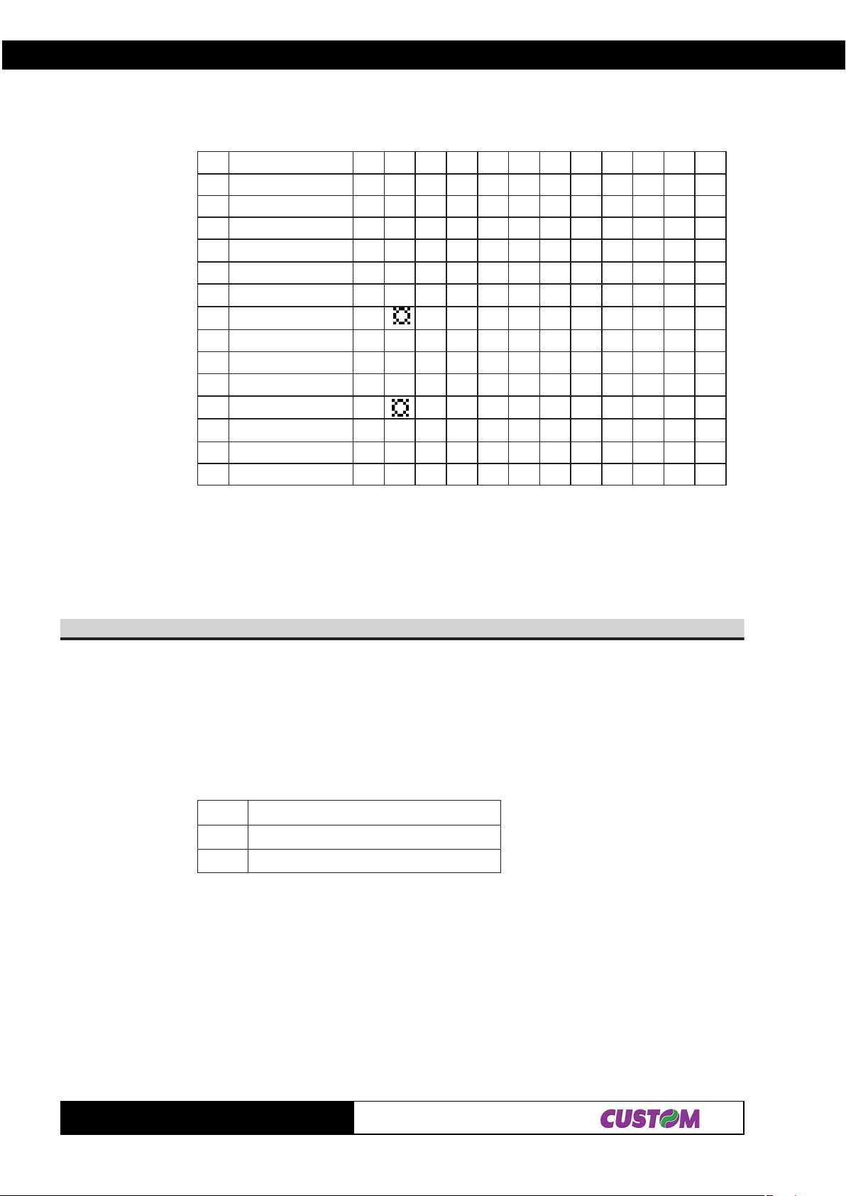
[Description] Selects the international character set by setting n as in the following table :
xeH324204B5C5D5E506B7C7D7E7
ntesretcarahC
0.A.S.U#$@[\]^`{|}~
1ecnarF#$à°ç§^`èùè"
2ynamreG#$§ÄÖÜ^`äöü
3niatirBtaerG£$@[\]^`{|}~
4IkramneD#$@Æ
5nedewS # ИДЦЕЬидцеь
6ylatI #$@° \и^щатим
71niapStP$@iÑ¿^`"ñ}~
8napaJ#$@[¥]^`{|}~
9yawroN#ÈÆ
01IIkramneD#$ÈÆ
112niapS#$àiÑ¿è`íñöú
21aciremAhtuoS#$àiÑ¿èùíñöú
Å^ `æ
∅
ÅÜèæ
∅
ÅÜèæ
∅
φ
φ
φ
β
å~
åü
åü
[Notes]
[Default]
[Reference]
[Example]
n65$B1$
[Name] Set print mode rotated by 90°.
[Format] ASCII ESC V n
Hex 1B 56 n
Decimal 27 86 n
[Range] 0 ≤ n ≤ 1
48 ≤ n ≤ 49
[Description] Enable / disable print mode rotated by 90°.n is used as follows :
nnoitcnuF
84,0edomnoitator°09ffosnruT
94,0edomnoitator°09nosnruT
[Notes] • When underlined mode is turned on, the printer does not underline 90° rotated charac-
ters. All the same it’ s possible select the underline mode.
• Double-width and double-height commands in 90° rotation mode enlarge characters in
the opposite directions from double-height and double-width commands in normal
mode.
• This command is not available in Page mode.
• If this command is entered in Page mode, the printer all the same save the setting.
Default] n = 0
[Reference] $1B $21 , $1B $2D
[Example]
TG1260/2460
2-14
Page 32

2. PRINTER FUNCTIONS
HnLnC5$B1$
[Name] Set relative print position.
[Format] ASCII ESC \ nL nH
Hex 1B 5C nL nH
Decimal 27 92 nL nH
[Range] 0 ≤ nL ≤ 255
0 ≤ nH ≤ 255
[Description] Sets the print starting position based on the current position by using the horizontal or
vertical motion unit.
This command sets the distance from the current position to [( nL+ nH × 256) ×
(horizontal or vertical motion unit)].
[Notes] • Any setting that exceeds the printable area is ignored.
• When the starting position is specified by n motion units to the right :
nL + nH × 256 = n
When the starting position is specified by n motion units to the left (negative direction)
use the complement of 65536 :
nL + nH × 256 = 65536 – n
• If setting exceeds printing area width, left or right margin is set to default value.
• The horizontal and vertical motion units are specified by $1D $50.
• The command $1D $50 can change the horizontal (and vertical) motion unit. However,
the value cannot be less than the minimum horizontal movement amount.
• In standard mode, the horizontal motion unit is used.
[Default]
[Reference] $1D $24, $1D $50
[Example]
n16$B1$
[Name] Select justification.
[Format] ASCII ESC a n
Hex 1B 61 n
Decimal 27 97 n
[Range] 0 ≤ n ≤ 2, 48 ≤ n ≤ 50
[Description] Aligns all the data in one line in the position specified. n selects the type of justification
as follows:
n Justification
0, 48 Left justification
1, 49 Centring
2, 50 Right justification
[Notes] • This command is only enabled if input at the beginning of the line.
• The lines are justified within the specified printing area.
• The spaces set by the commands $09, $1B $24 and $1B $ 5C remain justified as per
the previously set mode.
[Default] n = 0
[Reference]
[Example] Left justification Centering Right justification
ABC
ABCD
ABCDE
ABC
ABCD
ABCDE
ABC
ABCD
ABCDE
2-15
TG1260/2460
Page 33

2. PRINTER FUNCTIONS
n53$36$B1$
[Name] Enable or disable the front panel keys.
[Format] ASCII ESC c 5 n
Hex 1B 63 35 n
Decimal 27 99 53 n
[Range] 0 ≤ n ≤ 255
[Description] Enables or disables the front panel keys.
• When the LSB of n is 0, the panel keys are enabled.
• When the LSB of n is 1, the panel keys are disabled.
[Notes] • Only the LSB of n is effective.
• In the printer, the p anel buttons are the FEED and PRINT keys.
• When the panel keys are disabled, the keys can only operate when reset.
[Default] n = 0
[Reference] See the “Panel key” parameter from Setup.
[Example]
n46$B1$
[Name] Print and feed paper n lines.
[Format] ASCII ESC d n
Hex 1B 64 n
Decimal 27 100 n
[Range] 0 ≤ n ≤ 255
[Description] Prints the data in the print buffer and feeds the paper n lines.
[Notes] • This command sets the print starting position at the beginning of the line.
• This command does not affect the line spacing set by $1B $32 or $1B $33.
• The maximum paper feed amount is 200 lines. Even if a paper feed exceeding 200
lines is set, the printer only feeds the paper by 200 lines.
[Default]
[Reference] $1B $32, $1B $33
[Example]
96$B1$
[Name] Total cut.
[Format] ASCII ESC i
Hex 1B 69
Decimal 27 105
[Description] This command enables cutter operation; if there is no cutter, a disabling flag is set any
subsequent cutting commands will be ignored.
[Notes] • The printer waits until all the paper movement commands have been completed
before executing total cut
[Default]
[Reference]
[Example]
TG1260/2460
2-16
Page 34
2. PRINTER FUNCTIONS
n47$B1$
[Name] Select the character code table.
[Format] ASCII ESC t n
Hex 1B 74 n
Decimal 27 116 n
[Range] n = 0, 19, 255
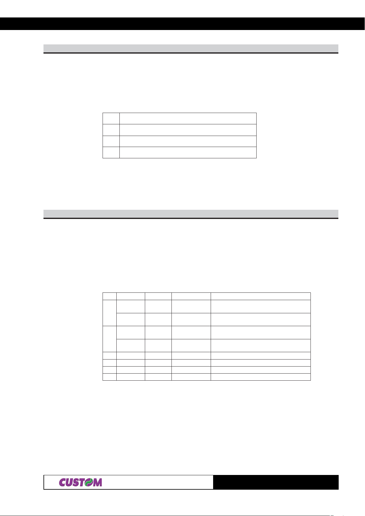
[Description] Selects a page n from the character code table, as follows:
negaP
0)]eporuEdradnatS,.A.S.U[734CP(0
91)312noitisoptalobmysoruErof858CP(91
552ecapsegaP
[Note]
[Default] n = 0
[Reference] See character code table
[Example] For printing Euro symbol (•), the command sequence is:
$1B, $74, $13, $D5
67$B1$
[Name] Transmit paper sensor status.
[Format] ASCII ESC v
Hex 1B 76
Decimal 27 118
[Description] Transmits the current paper sensor status upon receiving this command.
[Notes] • This command is executed immediately, even when the reception buffer is full (Busy ).
The status to be transmitted is shown in the table below :
tiBnO/ffOxeHlamiceDnoitcnuF
ffO000
01,
nO03 3
ffO000
3,2
nOC021
4ffO000 ffOotdexiF
5- - - DEVRESER
6- - - DEVRESER
7ffO000 ffOotdexiF
tneserprepaP
nesdnerepaP
tneserprepaP
dnerepaP
rosnesdnerepapraeN
rosnesdnerepapraeN
dnerepapraeN
ros
rosnesdnerepaP
[Default]
[Reference] $10 $04
[Example]
2-17
TG1260/2460
Page 35
2. PRINTER FUNCTIONS
n87$B1$
[Name] Select speed / quality mode.
[Format] ASCII ESC x n
Hex 1B 78 n
Decimal 27 120 n
[Range] 0 ≤ n ≤ 2
[Description] Selects speed / quality mode.
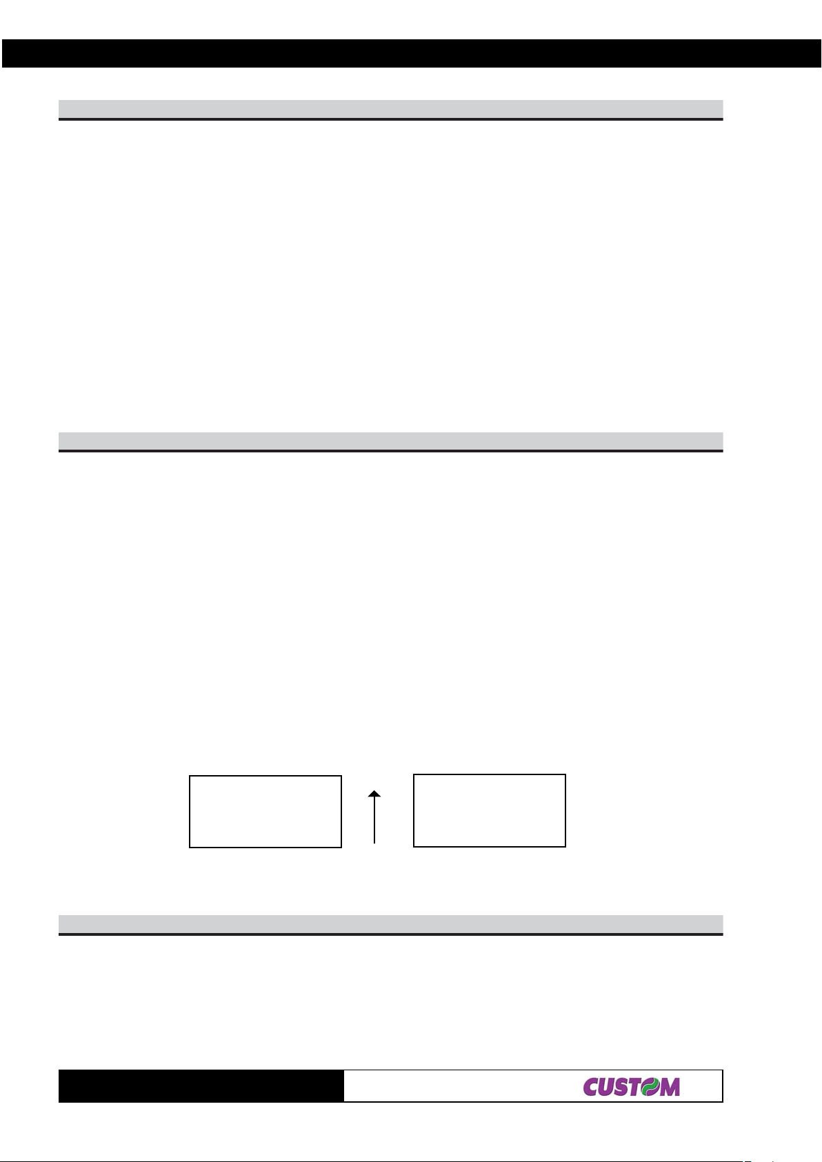
n Function
0 Draft mode (high speed)
1 Normal mode
2 High quality (low speed)
[Notes] • In high quality mode ( n= 2 ), the printer may be noisy.
[Default] n = 1
[Reference]
[Example]
nB7$B1$
[Name] Turn upside-down printing mode on/off.
[Format] ASCII ESC { n
Hex 1B 7B n
Decimal 27 123 n
[Range] 0 ≤ n ≤ 255
[Description] Turns upside-down printing mode on/of f.
• When the LSB of n is 0, upside-down printing mode is turned off.
• When the LSB of n is 1, upside-down printing mode is turned on.
[Notes] • Only the LSB of n is effective.
• This command is only enabled when input at the beginning of a line.
• In upside-down printing mode, the printer rotates the line to be printed by 180° and
then prints it.
[Default] n = 0
[Reference]
[Example]
Upside-down printing Off Upside-down printing On
ABCDEFG
0123456
ABCDEFG
0123456
Paper outfeed direction
LyHyLxHxnAF$B1$
[Name] Print graphic bank ( 448
[Format] ASCII ESC { } n xH x L yH yL
Hex 1B FA n xH xL yH yL
Decimal 27 250 n xH xL y H yL
TG1260/2460
××
× 1170 dots).
××
2-18
Page 36
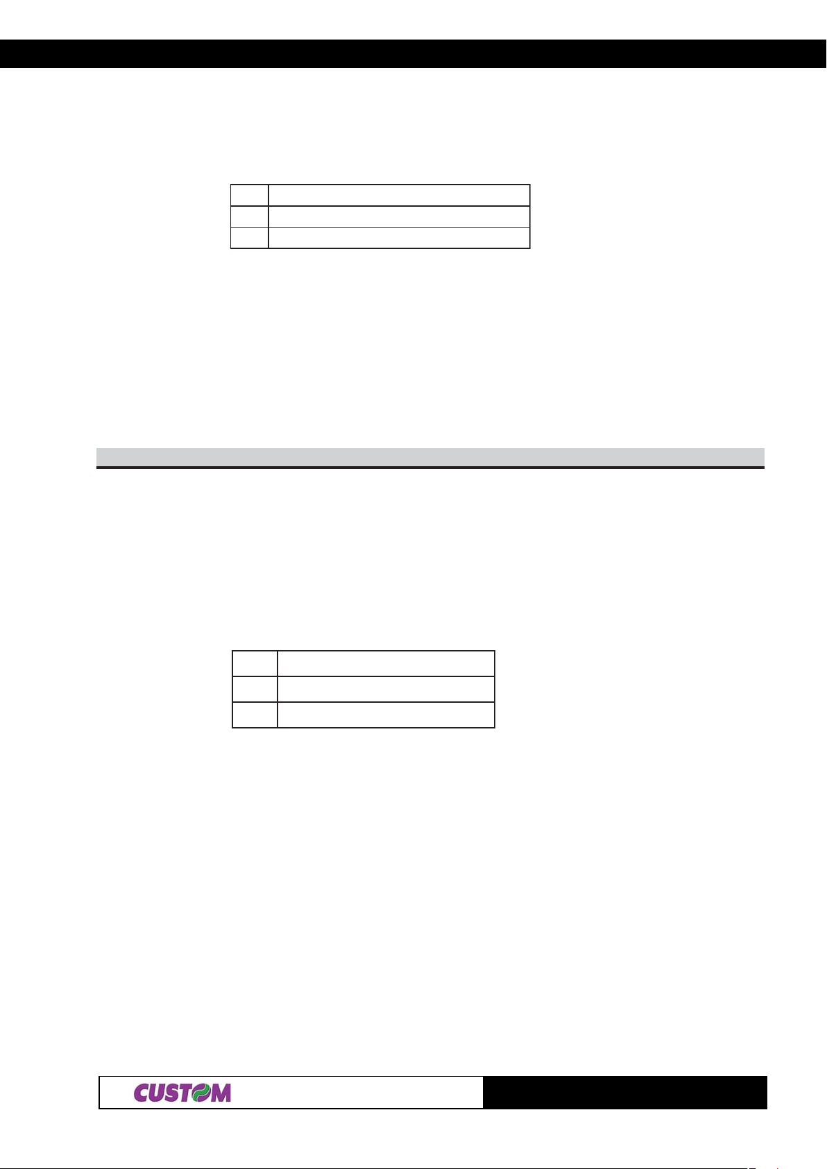
2. PRINTER FUNCTIONS
[Range] 1 ≤ n ≤ 2
0 ≤ xH, xL, yH, yL ≤ 255
[Description] Prints the graphics bank from flash or ram. n selects the bank as follows:
nnoitcnuF
11ogolknabhsalftnirP
22ogolknabhsalftnirP
xL + xH × 256 specifies the starting dot line ( 1 ÷ 1170).
yL + yH × 256 specifies the number of lines to print.
[Notes] • If (xL + (xH × 256)) > 1 170the printer does not execute the command.
• If ( xL + ( xH × 256 ) + yL +( yH × 256 ))> 1170the printer only prints 1170- xL + ( xH ×
256 ) +1 dotlines.
[Default]
[Reference]
[Example] T o print logo 1 from flash bank dotline 100 to dotline 299, send:
$1B $FA $01 $00 $64 $00 $C7
nd0dHnLnmFF$B1$
[Name] Receive and store logos in flash.
[Format] ASCII ESC { } m nL nH d0 dn
Hex 1B FF m n L nH d0 dn
Decimal 27 255 m nL nH d0 dn
[Range] 0 ≤ nL, nH ≤ 255 1 ≤ m ≤ 20 ≤ d0, dn ≤ 255
[Description] • Received [nL + (nH x 256)] x 2 bytes and store in the flash.
• If [nL + (nH x 256)] exceeds 32768, the data following will be processed as normal
data.
• Saved the graphics bank from flash. m selects the bank as follows:
mnoitcnuF
11knabhsalfotniepytogolevaS
22knabhsalfotniepytogolevaS
• d0, dn = value of bit stream image
[Default]
[Reference]
[Example] T o store the logotype indicated below ,into flash bank 2, necessity execute the follows
operation
1)Define the image dimensions.
The width of image is 448 horizontal pixel ; the height maximun of image is 1 170 vertical
pixel.
2) Calculate the number of bytes to send as (height pix*width pix)/16.
Bytes number in example is 448 x 1 170/16=32760 in exadecimal resulting =
7FF8.
3) Bit stream image conversion.
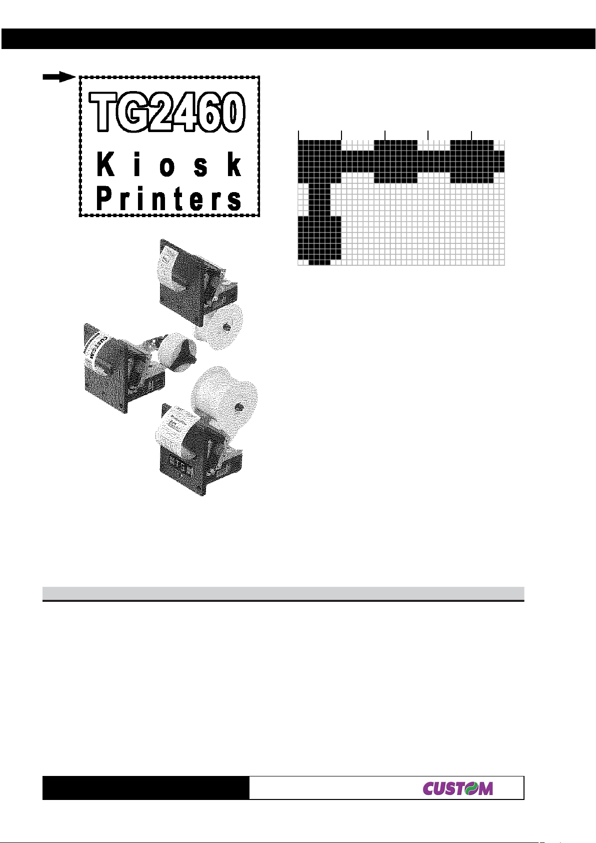
In the following figure is reproduced the logotype enlargement in the zone indicated by
the arrow to define d0...dn
2-19
TG1260/2460
Page 37
2. PRINTER FUNCTIONS
d0 d1 d2 d3
In this example; d0=FF; d1=03; d2=FC; d3=0F
Then send this command to the printer
0x1B 0xFF 0x02 0xF8 0x7F 0xFF 0 x 03 0xFC 0x0F ...
N. logo Dimension
43$0C$C1$
[Name] Total cut and automatic paper moving back.
[Format] ASCII FS { } 4
Hex 1C C0 34
Decimal 28 192 52
[Description] This command enables cutter operation and executes a total cut and automatic paper
moving back; if there is no cutter, a disabling flag is set any subsequent cutting
commands will be ignored.
[Notes] • The printer waits until all the paper movement commands have been completed before
executing total cut
[Default]
[Reference]
[Example]
TG1260/2460
2-20
Page 38
2. PRINTER FUNCTIONS
n12$D1$
[Name] Select character size.
[Format] ASCII GS ! n
Hex 1D 21 n
Decimal 29 33 n
[Range] 0 ≤ n ≤ 255
[Description] Selects character height and width, as follows:
• Bits 0 to 3 : character height selection ( see table 2 ).
• Bits 4 to 7 : character width selection ( see table 1 ).
T able1: Character width selection T able2: Character height selection
xeHlamiceDhtdiW
000 )lamron(1
0161(2)htdiwelbuod
0223(3htdiwelpurdauq)
0384
0446
0508
0669
07211
xeHamiceDl thgieH
000 )lamron(1
101 od(2thgiehelbu)
202 lpurdauq(3thgiehe)
303
404
505
606
707
[Notes] • This command is effective for all characters (except HRI characters).
• If n is outside the defined range, this command is ignored.
• When characters are enlarged with different heights on one line, the are aligned at the
baseline or topline (see $1D $7E).
• The character size can also be selected by the command $1B $21. However ,the
setting of the last received command is effective.
[Default] n = 0
[Reference] $1B $21
[Example]
A3$D1$
[Name] Start / end macro definition.
[Format] ASCII GS :
Hex 1D 3 A
Decimal 29 58
[Description] St art s or ends macro definition.
[Notes] • Macro definition starts when this command is received during normal operation.
• When the command $1D $5E is received during macro definition, the printer ends the
macro definitions and clears all definitions.
• Macro not defined when the power is turned on.
• The defined contents of the macro are not cleared by the command $1B $40.
Therefore, $1B $40 can be included in the contents of the macro definitions.
• If the printer receives the command $1D $3A again immediately after previously
receiving $1D $3A, the printer remains in the macro undefined state.
• The contents of the macro can be defined up to 1024 bytes. If the macro definition
exceeds 1024 bytes, the excess data is not not stored.
[Default]
[Reference] $1D $5E
[Example]
2-21
TG1260/2460
Page 39
2. PRINTER FUNCTIONS
n24$D1$
[Name] Turn white / black reverse printing mode on/off.
[Format] ASCII GS B n
Hex 1D 42 n
Decimal 29 66 n
[Range] 0 ≤ n ≤ 255
[Description] Turns white/black reverse printing mode on or off.
• When the LSB of n is 0, white/black reverse printing is turned off.
• When the LSB of n is 1, white/black reverse printing mode is turned on.
[Notes] • Only the LSB of nis effective.
• This command is available for built-in characters and user-defined characters.
• This command does not affect bit image, downloaded bit image, bar codes, HRI
characters and spacing skipped by $09, $1B $24 and $1B $5C.
• This command does not affect the space between lines.
• White/black reverse mode has a higher priority than underline mode. Even if underline
mode is on, it is disabled (but not cancelled) when white/black reverse mode is
selected.
[Default] n = 0
[Reference]
[Example]
mn03$34$D1$
[Name] Select counter print mode.
[Format] ASCII GS C 0 n m
Hex 1D 43 30 n m
Decimal 29 67 48 n m
[Range] 0 ≤ n ≤ 5
m = 0, 1, 2, 48, 49, 50
[Description] Selects a print mode for the serial number counter .
• n specifies the number of digits to be printed as follows:
when n = 0, the printer prints the actual digits indicated by the number value.
when n = 1 to 5, this command sets the number of digits to be printed.
• m specifies the printing position within the entire range of printed digits, as follows:
mnoitisopgnitnirPdeificepsesohtnahtsselstigidfognissecorP
84,0thgirngilA.tfelehtotsecapssddA
94,1thgirngilAsd
05,2tfelngilAthgirehtotsecapssddA
[Notes] • If n or m is out of the defined range, the previously set print mode is not changed.
• If n = 0, m does not have any meaning.
[Default] n = 0, m = 0
[Reference] $1D $43 $31, $1D $43 $32, $1D $43 $3B, $1D $63
[Example] n = 3,m = 0 n = 3, m = 1 n = 3, m=2
1 001 1
dA.tfelehtot’0‘
indicates a space
TG1260/2460
2-22
Page 40

2. PRINTER FUNCTIONS
rnHbLbHaLa13$34$D1$
[Name] Select count mode (A).
[Format] ASCII GS C 1 aL aH bL bH n r
Hex 1D 43 31 aL aH bL bH n r
Decimal 29 67 49 aL aH bL bH n r
[Range] 0 ≤ aL, aH ≤ 255
0 ≤ bL, bH ≤ 255
0 ≤ n, r ≤ 255
[Description] Selects a count mode for the serial number counter .
• aL, aH o bL, bH specify the counter range.
• n specify the stepping amount when counting up or down.
• r indicates the repetition number when the counter value is fixed.
[Notes] • Count-up mode is specified when:
[aL + (aH × 256)] < [bL + (bH × 256)] and n ≠ 0 and r ≠ 0
• Count-down mode is specified when:
[aL + (aH × 256)] > [bL + (bH × 256)] and n ≠ 0 and r ≠ 0
• Counting stops when:
[aL + (aH × 256)] = [bL + (bH × 256)] or n = 0 or r = 0
• In setting count-up mode, the minimum value of the counter is [aL + (aH × 256)] and
the maximum value is [bL + (bH × 256)]. If counting up reaches a value exceeding the
maximum, it is resumed with the minimum value.
• In setting count-down mode, the maximum value of the counter is [aL + (aH × 256)]
and the minimum value is [bL + (bH × 256)]. If counting down reaches a value less than
minimum, it is resumed with the maximum value.
• When the command is executed, the internal count that indicates the repetition
number specified by r is cleared.
[Default] aL = 1, aH = 0, bL = 255, bH = 255, n = 1, r = 1
[Reference] $1D $43 $30, $1D $43 $32, $1D $43 $3B, $1D $63
[Example]
HnLn23$34$D1$
[Name] Set counter.
[Format] ASCII GS C 2 nL nH
Hex 1D 43 32 nL nH
Decimal 29 67 50 nL nH
[Range] 0 ≤ nL, nH ≤ 255
[Description] Sets the serial number counter value.
• nL and nH determine the value of the serial number counter set by [nL + (nH × 256)].
[Notes] • In count-up mode, if the counter value specified by this command goes out of the
counter operation range specified by $1D $43 $31 or $1D $43 $3B, it is forced to
convert to the minimum value by $1D $63.
• In count-down mode, if the counter value specified by this command goes out of the
counter operation range specified by $1D $43 $31 or $1D $43 $3B, it is forced to
convert to the maximum value by $1D $63.
[Default] nL = 1, nH = 0
[Reference] $1D $43 $30, $1D $43 $31, $1D $43 $3B, $1D $63
[Example]
2-23
TG1260/2460
Page 41

2. PRINTER FUNCTIONS
B3$ csB3$ rsB3$ nsB3$ bsB3$ asB3$34$D1$
[Name] Select count mode.
[Format] ASCII GS C ; sa ; sb ; sn ; sr ; sc ;
Hex 1D 43 3B sa 3B sb 3B sn 3B sr 3B s c 3 B
Decimal 29 67 59 sa 59 sb 59 sn 59 sr 59 sc 59
[Range] 0 ≤ sa, sb, sc ≤ 65535
0 ≤ sn, sr ≤ 255
These values are all character strings.
[Description] Selects a count mode for the serial number counter and specifies the value of the
counter.
• sa, sb, sn, sr and sc are all displayed in ASCII characters using the codes from ‘O’ to
‘9’.
• sa and sb specify the counter range.
• sn indicates the stepping amount for counting up or down.
• sr indicates the repetition number with the counter value fixed.
• sc indicates the counter value.
[Notes] • Count-up mode is specified when:
sa < sb and sn ≠ 0 and sr ≠ 0
• Count-down mode is specified when:
sa > sb and sn ≠ 0 and sr ≠ 0
• Counting stops when:
sa = sb or sn = 0 or sr = 0
• In setting count-up mode, the minimum value of the counter is sa and the maximum is
sb. If counting up reaches a value exceeding the maximum, it is resumed with the
minimum value. If the counter value set by sc is outside the counter operation range,
the counter value is forced to convert to the minimum value by executing $1D $63.
• In setting count-down mode, the maximum value of the counter is sa and the
minimum value is sb. If counting down reaches a value less than the minimum, it is
resumed with the maximum value. If the counter value set by sc is outside the counter
operation range, the counter value is forced to convert to the maximum value by
executing $1D $63.
• Parameters sa to sc can be omitted. If omitted, these values remain unchanged.
• Parameters sa to sc must not contain characters, with the exception of those from ‘0’
to ‘9’.
[Default] sa = 1, sb = 65535, sn = 1, sr = 1, sc = 1
[Reference] $1D $43 $30, $1D $43 $31, $1D $43 $32, $1D $63
[Example]
n84$D1$
[Name] Select printing position of Human Readable Interpretation (HRI)
[Format] ASCII GS H n
Hex 1D 48 n
Decimal 29 72 n
[Range] 0 ≤ n ≤ 3, 48 ≤ n ≤ 51
[Description] Selects the printing position of HRI characters when printing bar code.
n selects the printing position as follows:
nnuFnoitc
84,0oNdetnirpt
94,1ehtevobA.edocrab
05,2woleB.edocrabeht
15,3dnaevobahtoBwoleb.edocrabeht
TG1260/2460
2-24
Page 42
2. PRINTER FUNCTIONS
[Notes] • HRI characters are printed using the font specified by GS f.
[Default] n = 0
[Reference] $1D $66, $1D $6B
[Example]
n94$D1$
[Name] Transmit printer ID.
[Format] ASCII GS I n
Hex 1D 49 n
Decimal 29 73 n
[Range] 1 ≤ n ≤ 3, 49 ≤ n ≤ 51
[Description] Transmits the printer ID specified by n as follows:
nretnirPDInoitacificepS
94,1DIledomretnirP)0642GT(D6$
05,2DIepyTolebelbatotrefeRw
3, 15InoisrevMORD )rahc4(noisrevMORno
sdnepeD
n = 2, Identification Function
tiB
0
1
2
3- - - DEVRESER
4
5- - - DEVRESER
6
7ffO000 ffOotdexiF
nO/ffOxeHlamiceDnuFnoitc
ffO000 detroppustonsedocretcarahcetyb-2
ffO000 deilppustonrettucotuA
nO202 deilppusrettuco
ffO000 repaplamrehtlebal-noN
nO404 repaplamrehtlebaL
ffO000 ffOotdexiF
-- - DEVRESER
tuA
[Notes] • When the DTR/DSR control is selected, the printer only transmits 1 byte (Printer
identification) after it has been given confirmation that the host is ready to receive data.
If the host is not ready , the printer waits until it is.
• When the XON/XOFF control is selected, the printer only transmits 1 byte (Printer
identification) if it has not been given confirmation that the host is ready to receive data.
• This command is carried out once the data has been processed in the reception
buffer . There may therefore be a delay between the moment in which the command is
received and that in which the data is transmitted, depending on the status of the
reception buffer
.[Default]
[Reference]
[Example]
HnLnC4$D1$
[Name] Set left margin.
[Format] ASCII GS L nL nH
Hex 1D 4C nL nH
Decimal 29 76 nL nH
[Range] 0 ≤ nL, nH ≤ 255
[Description] Sets the left margin.
• The left margin is set at [(nL + nH × 256) × (horizontal motion unit)] inches.
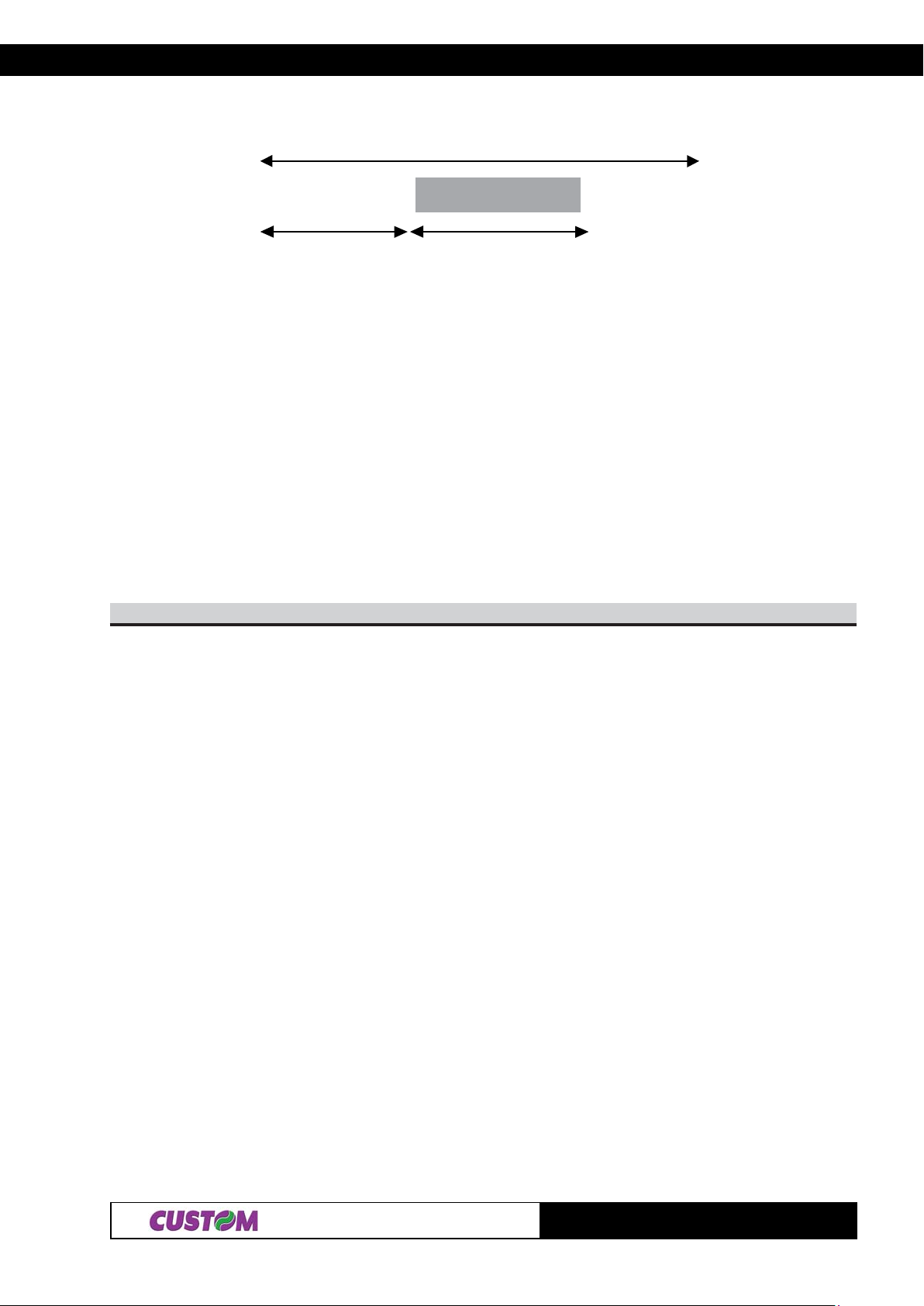
Printable area
2-25
TG1260/2460
Page 43

2. PRINTER FUNCTIONS
Left margin Width of print area
[Notes] • This command is enabled only at the beginning of the line.
• If the setting exceeds the printable area, the maximum value of the printable area is
used.
• If left margin + printing area width is greater than printable area, then printing area
width is set at maximum value.
• The horizontal and vertical motion units are specified by $1D $50. Changing the
horizontal or vertical motion unit does not affect the current left margin.
• The command $1D $50 can change the horizontal (and vertical) motion unit.
• However, the value cannot be less than the minimum horizont al movement amount
and it must be expressed in even units of the minimum horizontal movement amount.
[Default] If Font A : nL = nH = 0
If Font B : nL =14
nH = 0
[Reference] $1D $50, $1D $57
[Example]
yx05$D1$
[Name] Set horizontal and vertical motion units.
[Format] ASCII GS P x y
Hex 1D 50 x y
Decimal 29 80 x y
[Range] x = 100, 200
y = 100, 200
[Description] Sets the horizontal and vertical motion units at 1/x inches and 1/y inches, respectively .
When x is set at 0, the default setting value is used.
When y is set at 0, the default setting value is used.
[Notes] • The horizontal direction is perpendicular to the paper feed direction.
• In standard mode, the following commands use x or y, irrespective of character
rotation (upside down or 90° clockwise rotation):
Commands using x : $1B $20, $1B $24, $1B $5C, $1D $4C, $1D $57.
Commands using y : $1B $33, $1B $4A.
• This command does not affect the previously specified values.
• The calculated result from combining this command with others is truncated to the
minimum value of the mechanical pitch or an exact multiple of that value.
[Default] x = 200, y = 200
[Reference] $1B $20, $1B 24, $1B $5C, $1B $33, $1B $4A, $1D $4C, $1D $57
[Example]
HnLn75$D1$
[Name] Set printing area width.
[Format] ASCII GS W nL nH
Hex 1D 57 nL nH
Decimal 29 87 nL nH
[Range] 0 ≤ nL, nH ≤ 255
[Description] Sets the printing area width to the area specified by nL and nH.
TG1260/2460
2-26
Page 44
2. PRINTER FUNCTIONS
• The left margin is set at [(nL + nH × 256) × (horizontal motion unit)] inches.
Printable area
Left margin Width of print area
[Notes] • This command is only enabled at the beginning of the line.
• If right margin is greater than printable area, then the printing area width is set at
maximum value.
• If printing area width = 0, then it is set at maximum value.
• The horizontal and vertical motion unit are specified by $1D $50. Changing the
horizontal or vertical motion unit does not affect the current left margin.
• The command $1D $50 can change the horizontal (and vertical) motion unit.
• However, the value cannot be less than the minimum horizont al movement amount
and it must be expressed in even units of the minimum horizontal movement amount.
[Default] If Font A : nL = 192
nH = 1
If Font B : nL =164
nH = 1
[Reference] $1D $4C, $1D $50
[Example]
mtrE5$D1$
[Name] Execute macro.
[Format] ASCII GS ^ r t m
Hex 1D 5E r t m
Decimal 29 94 r t m
[Range] 0 ≤ r, t ≤ 255
0 ≤ m ≤ 1
[Description] Executes a macro.
• r specifies the number of times to execute the macro.
• t specifies the waiting time for executing the macro.
The waiting time is t× 100 msec. for every macro execution.
• m specifies macro executing mode:
When the LSB of m = 0, the macro executes r times continuously at the interval
specified t.
When the LSB of m = 1, after waiting for the period specified by t, the LED indicator
blinks and the printer waits for the FEED button to be pressed. After the button is
pressed, the printer executes the macro once. The printer repeats the operation r
times.
[Notes] • This command lasts for a period of (t × 100 msec.) after a macro is executed by t.
• If this command is received while a macro is being defined, the macro definition is
aborted and the definitions cleared.
• If the macro is not defined or if r is 0, nothing happens.
• When the macro is executed by pressing the FEED button (m = 1), the paper can not
be fed by using the FEED button.
[Default]
[Reference] $1D $3A
[Example]
2-27
TG1260/2460
Page 45
2. PRINTER FUNCTIONS
36$D1$
[Name] Print counter.
[Format] ASCII GS c
Hex 1D 63
Decimal 29 99
[Description] Sets the serial counter value in the print buffer and increments or decrements the counter
value.
[Notes] • After setting the current counter value in the print buffer as print data (a character
string), the printer counts up or down based on the count mode set. The counter value
in the print buffer is printed when the printer receives a print command or is in the buffer
full state.
• The counter print mode is set by $1D $43 $30.
• The counter mode is set by $1D $43 $31 or $1D $43 $3B.
• In count-up mode, if the counter value set by this command goes out of the counter
operation range set by $1D $43 $31 or $1D $43 $3B, it is forced to convert to the
minimum value.
• In count-down mode, if the counter value set by this command goes out of the counter
operation range set by $1D $43 $31 or $1D $43 $3B, it is forced to convert to the
maximum value.
[Default]
[Reference] $1D $43 $30, $1D $43 $31, $1D $43 $32, $1D $43 $3B
[Example]
n66$D1$
[Name] Select font for HRI characters.
[Format] ASCII GS f n
Hex 1D 66 n
Decimal 29 102 n
[Range] n = 0, 1, 48, 49
[Description] Selects a font for the HRI characters used when printing a bar code.
n selects a font from the following table:
ntnoF
[Notes] The HRI characters are printed at the position specified by the command $1D $48.
[Default] n = 0
[Reference] $1D $48, $1D $6B
[Example]
84,0.AtnoF
94,1.BtnoF
n86$D1$
[Name] Set bar code height
[Format] ASCII GS h n
Hex 1D 68 n
Decimal 29 104 n
[Range] 1 ≤ n ≤ 255
[Description] Sets the height of the bar code. n specifies the number of dots in the vertical direction.
[Notes]
[Default] n = 96 (12 mm)
TG1260/2460
2-28
Page 46
2. PRINTER FUNCTIONS
[Reference] $1D $6B
[Example]
00$]kd...1d[mB6$D1$ ]nd...1d[nmB6$D1$
[Name] Print bar code.
[Format] ASCII GS k m NUL
Hex 1D 6B m 00
Decimal 29 107 m 0
ASCII GS k m n
Hex 1D 6B m n
Decimal 29 107 m n
[Range] 0 ≤ m ≤ 6
65 ≤ m ≤ 73
[Description] Selects a bar code system and prints the bar code. m selects a bar code system as
follows:
mB metsysedocrasretcarahcforebmuNskrameR
0A-CPU11 ≤ k ≤ 2184 ≤ d ≤ 75
1E-CPU11 ≤ k ≤ 2184 ≤ d ≤ 75
2)NAJ(31NAE21 ≤ k ≤ 3184 ≤ d ≤ 75
3)NAJ(8NAE7
493EDOC1≤ k
5FTI1≤ (krebmunneve) 84 ≤ d ≤ 75
6RABADOC1≤ k
739EDOC1≤ k ≤ 5521≤ d ≤ 721
8821EDOC2≤ k ≤ 5521≤ d ≤ 721
0223EDOC8≤ k ≤ 984 ≤ d ≤ 75
≤ k ≤ 884 ≤ d ≤ 75
84 ≤ d ≤ 56,75 ≤ d ≤ ,73,63,23,09
84 ≤ d ≤ 56,75 ≤ 1d ≤ ,34
74,64,54,34
,63,86
85,74,64,54
56A-CPU11 ≤ n ≤ 2184 ≤ d ≤ 75
66E-CPU11 ≤ n ≤ 2184 ≤ d ≤ 75
76)NAJ(31NAE21 ≤ n ≤ 3184 ≤ d ≤ 75
86)NAJ(8NAE7≤ n ≤ 884 ≤ d ≤ 75
84 ≤ d ≤ 56,
9693EDOC1≤ n ≤ 552
07FTI1≤ n ≤ 55284 ≤ d ≤ 75
17RABADOC1≤ n ≤ 552
2739EDOC1≤ n ≤ 5520≤ d ≤ 721
37821EDOC2≤ n ≤ 5520≤ d ≤ 721
0923EDOC8≤ n ≤ 984 ≤ d ≤ 75
75 ≤ d ≤ ,73,63,23,09
74,64,54,34
84 ≤ d ≤ 56,75 ≤ 1d ≤ ,34,63,86
85,74,64,54
[Notes] • If d is outside the specified range, the printer prints the following message: “BAR
CODE GENERATOR NON OK !” and processes the following data as normal data.
• If the horizontal size exceeds the printing area, the printer only feeds the paper .
• This command feeds as much paper as is required to print the bar code, irrespective
of the line spacing specified by $1B $32 or $1B $33.
2-29
TG1260/2460
Page 47
2. PRINTER FUNCTIONS
• Af ter printing the bar code, this command sets the print position at the beginning of the
line.
• This command is not affected by print modes (bold, double strike, underline or
character size), with the exception of upside-down mode and justification.
[Note for ] • This command ends with a $00 code.
• When the bar code used is UPC-A or UPC-E, the printer prints the bar code data after
receiving 1 1 (without check digit) or 12 ( with check digit) byte bar code dat a.
• When the bar code system used is EAN13, the printer prints the bar code after
receiving 12 (without check digit) or 13 (with check digit) byte bar code data.
• When the system used is EAN8, the printer prints the bar code after receiving 7
(without check digit) or 8 (with check digit) byte bar code data.
• The number of data for ITF bar code must be even. When an odd number of data is
input, the printer ignores the last received data.
[Note for ] • If n is outside the specified range, the printer stops command processing and process
the following data as normal data.
When to use
CODE93: • The printer prints an HRI character ( o ) as a start character at the beginning of the HRI
character string.
• The printer prints an HRI character ( o ) as a stop character at the end of the HRI
character string.
• The printer prints an HRI character ( n ) as a control character ( $00 to $1F and $7F).
When to use
CODE128: • When using the CODE128 in this printer, take the following points into account for
data transmission:
• The top of the bar code data string must be a code set selection character (CODE A ,
CODE B or CODE C) which selects the first code set.
• Special characters are defined by combining two characters “{“ and one character.
The ASCII character “{” is defined by transmitting “{“ twice consecutively.
retcarahccificepS
TFIHSS{35,B738,321
AEDOCA{14,B756,321
BEDOCB{24,B766,321
CEDOCC{34,B77
1CNF1{13,B794,321
2CNF2{23,B705,321
3CNF3{33,B715,321
4CNF4{43,B725,321
'{'{{B7,B7321,321
IICSAxeHlamiceD
[Default]
[Reference] $1D $48, $1D $66, $1D $68, $1D $77
[Example]
n27$D1$
[Name] Transmit st atus.
[Format] ASCII GS r n
Hex 1D 72 n
Decimal 29 114 n
[Range] n = 1, n = 49
noissimsnartataD
6,321
TG1260/2460
2-30
Page 48
2. PRINTER FUNCTIONS
[Description] Transmits the status specified by n as follows:
n Function
1, 49 Transmits paper sensor status (same as $1B $76).
tiB
0,1
2,3
4ffO000 ffOotdexiF
5- - - .DEVRESER
6
7ffO000 ffOotdexiF
nO/ffOxeHlamiceDnoitcnuF
-- - .DEVRESER
-- - .DEVRESER
ffO000 tneserprepap:rosnesdnerepaP
On 0C 21tneserptonrepap:rosnesdner
-- - .DEVRESER
epaP
[Notes] • This command is executed when the data is processed in the reception buffer. There
may therefore be a time lag between receiving the command and transmitting the
status, depending on the status of the reception buffer .
[Default]
[Reference] $10 $04, $1B $75, $1B $76
[Example]
nwSG
[Name] Set bar code width.
[Format] ASCII GS w n
Hex 1D 77 n
Decimal 29 119 n
[Range] 2 ≤ n ≤ 6
[Description] Sets the horizontal size of the bar code. n specifies the bar code width as follows:
n)mm(htdiweludoM
252.0
3573.0
45.0
5526.0
657.0
[Notes]
[Default] n = 3
[Reference] $1D $6B
[Example]
nE7$D1$
[Name] Set superscript / subscript.
[Format] ASCII GS { } n
Hex 1D 7E n
Decimal 29 126 n
2-31
TG1260/2460
Page 49
2. PRINTER FUNCTIONS
[Range] n = 0, 1, 48, 49
[Description] Sets superscript or subscript character position.
n specifies the position as follows:
nnuFnoitc
84,0.noitisopretcarahctpircsbuS
94,1.noitisopretcarahctpircsrepuS
[Notes] • This command is executed if there are characters with different heights on the same
line.
[Default] n = 0
[Reference] $1B $21, $1D $21
[Exa
[Name] Set printing density.
[Format] ASCII GS { } n
[Range] 0 ≤ n ≤ 4, 48 ≤ n ≤ 52
nC7$D1$
Hex 1D 7 C n
Decimal 29 124 n
[Notes] • The printing density is cleared at default value when the printer is reset or the power is
turned off.
[Default] n = 2
[Description] Sets the printing density. n specifies the printing density as follows:
nytisnedgnitnirP
84,0thgilyreV
94,1thgiL
05,2lamroN
15,3kraD
25,4kradyreV
[Reference]
[Example]
TG1260/2460
2-32
Page 50
2. PRINTER FUNCTIONS
2.1.2 Custom emulation
The following table lists all the commands for the management of the Custom emulation. The commands
can be transmitted to the printer at any moment, but they will only be carried out when the commands
previously transmitted have been carried out. There are no priority commands; all commands are carried out
when the circular buffer is free to do so.
COMMAND T ABLE
XEH.moCIICSA.moCnoitpircseD
00$LUNsretcarahcllamshtiwgnitnirP
10$HOSsretcarahchtdiwelbuodhtiwgnitnirP
20$XTSsret
30$XTEsretcarahcdednapxehtiwgnitnirP
40$TOEsretcarahcllamshtiwgnitnirperotseR
0$FLdeefenildnatnirP
A
B0$nTVnsbatlacitreV
D0$RCdeefdnatnirP
F0$ISD0$erongI
11$1CDedomcihparg04/42PD
n12$B1$n!CSEedomtni
HnLn42$B1$HnLn$CSEnoitisopetulosbateS
kd...1dHnLnmA2$B1$kd...1dHnLnm*CSEedomegamitibteS
04$B1$@CSEretnir
24$B1$BCSE1TNOFtceleS
34$B1$CCSEtuclatoT
D0$B4$B1$RC]d[KCSE yek"tnirP"gnisserpnotimsnartotsretcara
74$B1$GCSEsretemaraptluafedteS
D4$B1$MCSEedomtnirpfosretemaraptluafedteS
E4$B1$NCSELAMRONnignitnirpteS
$B1$RCSEESREVERnignitnirpteS
25
65$B1$VCSE°09ybdetatoredomtnirpteS
n16$B1$)n(aCSEnoitacifitsujtceleS
26$B1$bCSE2tno
D6$B1$mCSEedomtnirpfosretemaraptluafeddaeR
07$B1$pCSEsretemaraptluafeddaeR
27$B1$rCSEnoitacolMORPEEdaeR
7$B1$ntCSEelbatedocretcarahctceleS
n4
77$B1$wCSEnoitacolMORPEEetirW
LyHyLxHxnAF$B1$LyHyLxHxn·CSEknabcihpargtnirP
nd0dHnLnmFF$B1$HnLn}{CSEhsalFnisogolerotsdnaevieceR
43$0C$C1$4}{SFkcabgnivomrepapcitamotuadnatuclatoT
$FFSGstnetnocreffubehttnirP
C0$D1
A3$D1$:SGnoitinifedorcamfodne/gnitratsteS
mn03$34$D1$mn0CSGedomtnirpretnuoctceleS
43$0C$C1$4}{SFkcabgnivomrepapcitamotuadnatuclatoT
LbHaLa13$34$D1$
rnHb
n23$34$D1$HnLn2CSGretnuoctceleS
HnL
r
nHbLbHaLa1CSG
rpteS
pezilaitinI
hcteS
fteS
)A(edomtnuoctceleS
carahcthgiehelbuodnignitnirP
(Tab.2.2)
2-33
TG1260/2460
Page 51
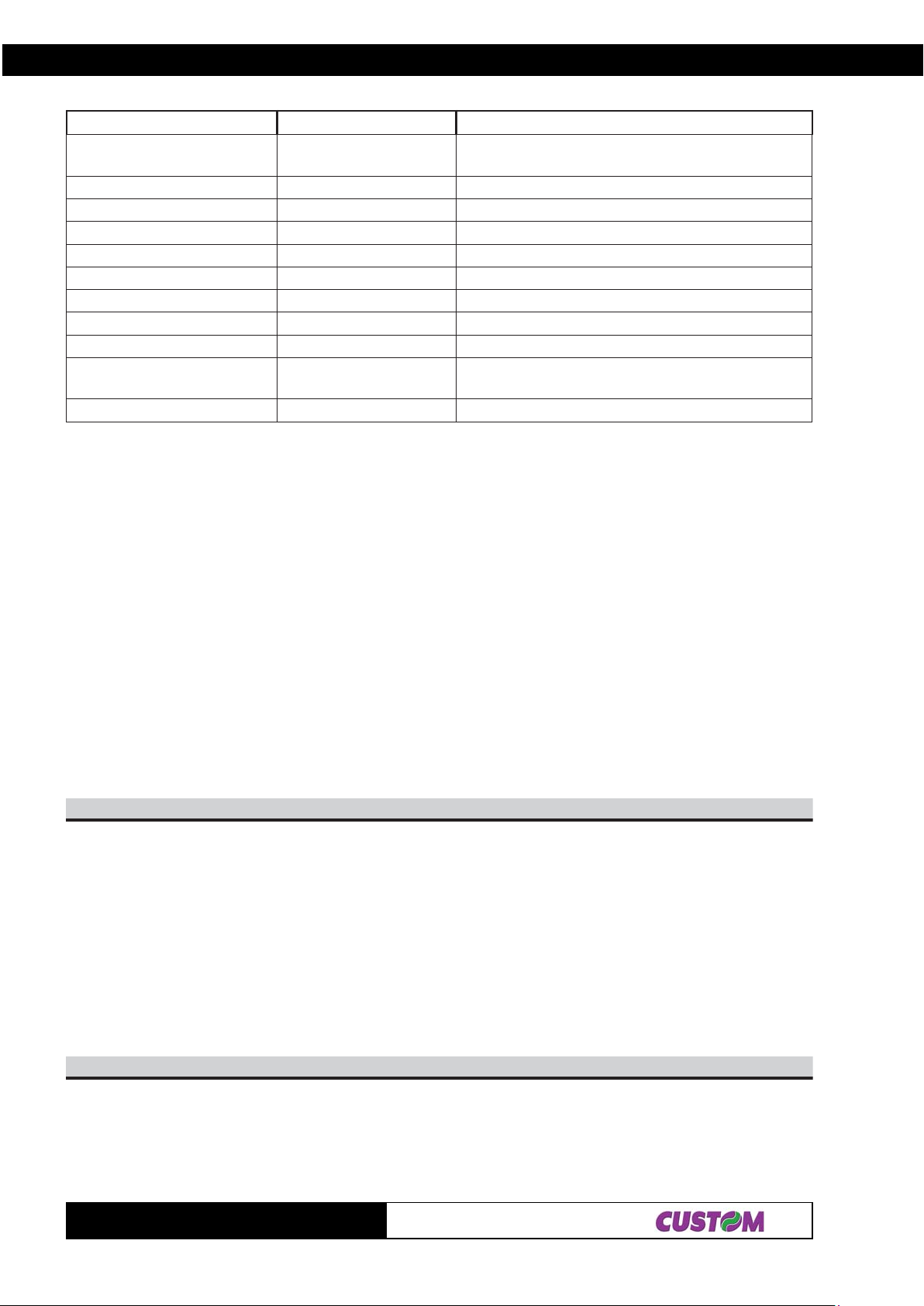
2. PRINTER FUNCTIONS
XEH.moCIICSA.moCnoitpircseD
bsB3$asB3$34$D1$
B3$csB3$rsB3$nsB3$
1$nHSGsretcarahcIRHfonoitisopgnitnirptceleS
NOTE: in “Note” column where the model is not specified, the command is valid for all models.
The following pages provide a more detailed description of each command.
n84$D
n94$D1$nISGDIretnirptimsnarT
yx05$D1$yxPSGstinunoitomlacitrevdnal
mtrE5$D1$mtr^SGorcametucexE
36$D1$cSGretnuoctnirP
n66$D1$nfSGsretcarahcIRHroftnoftceleS
n86$D1$nhSGe
00mB6$D1$LUNmkSGedocrabtnirP
n77$D1$nwSG
C7$D1$n|SGytisnedgnitnirpteS
n
;cs;
rs;ns;bs;as;CSG
atnozirohteS
edoc
)B(edomtnuoctceleS
docrabfothgiehtceleS
rabfo)noitacifingam(ezislatnozirohtceleS
[Name] Print with small character
[Format] ASCII NUL
Hex 00
Decimal 0
[Description] Character printing is executed in small format (normal)
[Notes] • Setting remains until the next set
[Default] Set up from front keys.
[Reference] $01, $02, $03, $04
[Example]
10$
[Name] Printing with double width character
[Format] ASCII SOH
Hex 01
Decimal 1
[Description] Printing of the character is executed in double width format
[Notes] • Setting remains until next set
[Default] Set up from front keys.
[Reference] $00, $02, $03, $04
[Example]
20$
[Name] Printing in double height character
[Format] ASCII STX
Hex 02
Decimal 2
[Description] Printing of the character is executed in double height format
TG1260/2460
2-34
Page 52

2. PRINTER FUNCTIONS
[Notes] • Setting remains until next set
[Default] Set up from front keys.
[Reference] $00, $01, $03, $04
[Example]
30$
[Name] Printing with expanded character
[Format] ASCII ETX
Hex 03
Decimal 3
[Description] Printing of the character is executed in expanded format
[Notes] • Setting remains until next set
[Default] Set up from front keys.
[Reference] $00, $01, $02, $04
[Example]
40$
[Name] Print with small character
[Format] ASCII EOT
Hex 04
Decimal 4
[Description] Character printing is executed in small format (normal)
[Notes] • Setting remains until next set
[Default] Set up from front keys.
[Reference] $00, $01, $02, $03
[Example]
A0$
[Name] Line feed
[Format] ASCII LF
Hex 0 A
Decimal 10
[Description] Prints the data in the buffer and feeds one line, based on the current line spacing.
[Notes] • The command sets the print position at the beginning of the line.
[Default]
[Reference] $1B $32, $1B $33
[Example]
B0$)n(
[Name] Vertical t abs
[Format] ASCII n VT
Hex n 0B
Decimal n 11
[Range] 0 < n ≤ 9
[Description] Runs as many feeds as are defined by n.
[Notes] • This command zeroes the line buffer
2-35
TG1260/2460
Page 53

2. PRINTER FUNCTIONS
[Default]
[Reference]
[Example]
D0$
[Name] Print and line feed
[Format] ASCII CR
Hex 0D
Decimal 13
[Description] This command prints the data in the buffer.
[Notes] • This command sets the print position at the beginning of the line.
[Default]
[Reference] $0A
[Example]
F0$
[Name] Ignore CR
[Format] ASCII SI
Hex 0F
Decimal 15
[Description] After this command the CR code is ignored.
[Notes] • T o put the CR code back into operation, reset the printer.
[Default]
[Reference]
[Example]
11$
[Name] Graphic mode DP24/40
[Format] ASCII DC1
Hex 11
Decimal 17
[Description] Prints in graphic mode like the DP 24/40.
The command $1 1 enables the DP24-40 printer graphic mode, i.e. to print in graphic
mode, transmit the command $1 1 at the beginning of each line. One line for the DP24-
40 printer (24 column model) corresponds to 44 horizontal dots divided into 24 6-dot
blocks. For the DP24-40 printer (40-column model) one line corresponds to 240
horizontal dots divided into 40 6-dot blocks.
[Notes] The size of the graphic dot and the number of dots per line vary depending on the
number of columns.
To obtain a graphic printout, enter the command $11 at the beginning of each line. The
graphic configuration byte format is as follows:
X R P6 P5 P4 P3 P2 P1
D7D6 D5 D4 D3 D2 D1 D0
where:
X is not utilized (we recommend 0);
R must be set at 1;
P1, P6 are the data of the graphic dots (1 prints, 0 does not print).
The P6 bit of the string of dots transmitted, is printed on the left and the others (P5, P4,
TG1260/2460
2-36
Page 54
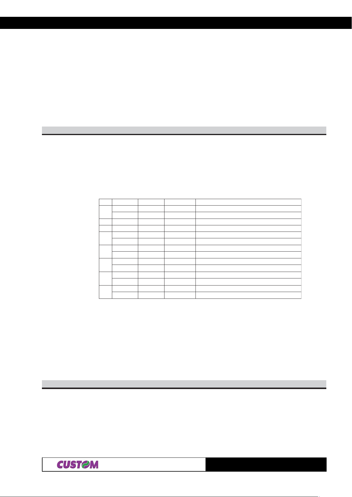
2. PRINTER FUNCTIONS
P3, P2, P1) follow from left to right as shown:
1st byte
2nd byte
P6 P5 P4 P3 P2 P1 P6 P5 P4 P3 P2 P1 P6 P5 P4 P3 P2 P1
[Default]
[Reference]
[Example] To print a line of dots, transmit:
$1 1, n x $7F (where n is the number of characters per line), $0D.
To print an empty line, transmit:
$1 1, n x $40, $0D.
n12$B1$
[Name] Select print modes.
[Format] ASCII E S C ! n
Hex 1B 21 n
Decimal 27 33 n
[Range] 0 ≤ n ≤ 255
[Description] Selects the print mode using n (see following tables):
3rd byte
tiBnO/ffOxeHlamiceDnuFnoitc
0ffO000 .detcelesAtnofretcarahC
nO101 .detcelesBtnofretcarahC
1- - - .DEVRESER
2- - - .DEVRESER
3ffO000 .detcel
nO808 .detcelesedomdloB
4ffO000 .detcelestonedomthgiehelbuoD
nO0161.detcelesedomthgiehelbuoD
5ffO000 .detcel
nO0223.detcelesedomhtdiwelbuoD
6ffO000 .detcelestonedomtpircS
nO0446detcelesedomtpircS.
7ffO000 .detc
nO08821.detcelesedomenilrednU
estonedomdloB
estonedomhtdiwelbuoD
elestonedomenilrednU
[Notes] • The printer can underline all the characters, but it cannot underline the space set by
command $1B $24 and 90° clockwise rotated characters.
• When the characters on the same line are enlarged to different heights, they are either
aligned at the baseline or topline.
• This command resets the left and right margin at the default value.
[Default] n = 0
[Reference]
[Example]
HnLn42$B1$
[Name] Set absolute print position
[Format] ASCII ESC $ nL nH
Hex 1B 24 nL nH
Decimal 27 36 nL nH
[Range] 0 ≤ nL ≤ 255
2-37
TG1260/2460
Page 55
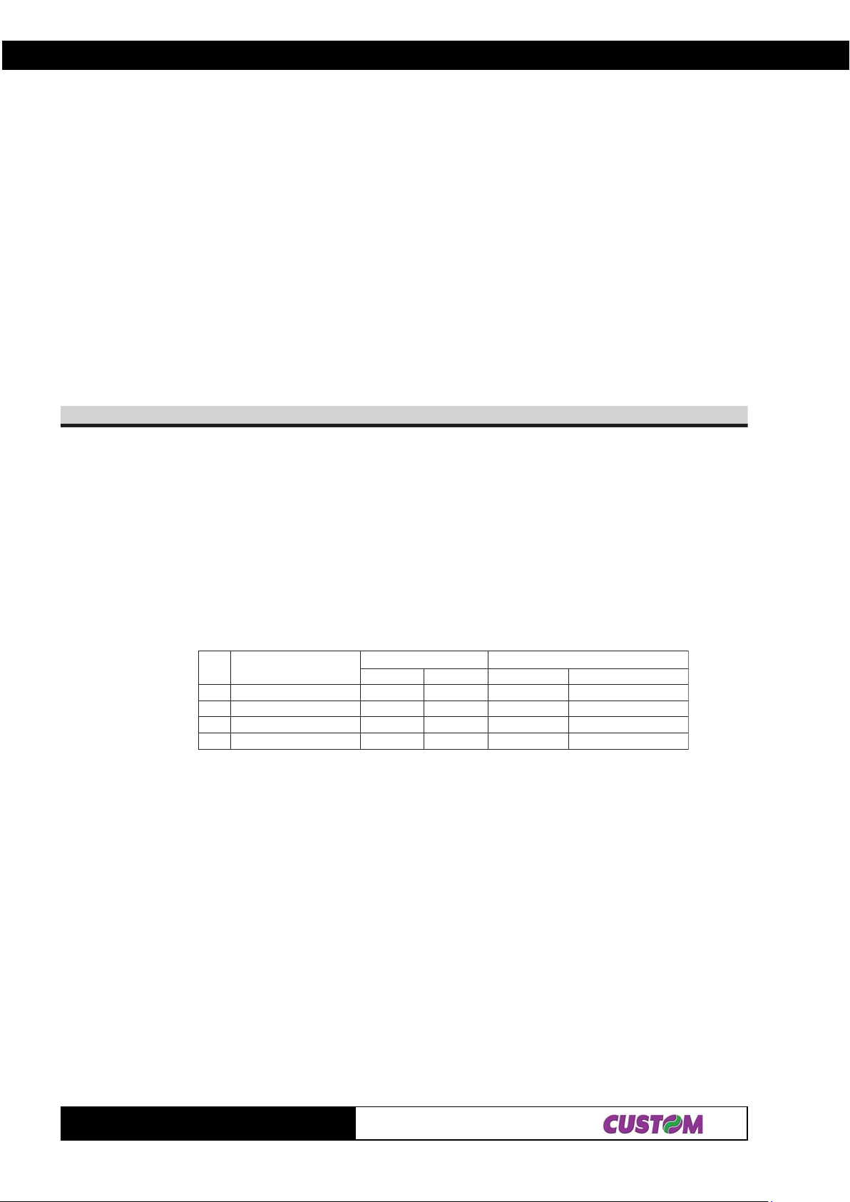
2. PRINTER FUNCTIONS
0 ≤ nH ≤ 255
[Description] Sets the distance from the beginning of the line to the position in which the subsequent
characters are to be printed.
The distance from the beginning of the line to the print position is [(nL + nH × 256)×
(vertical or horizontal motion unit)] inches.
[Notes] • Settings outside the specified printable area are ignored.
• The vertical and horizontal motion units are specified by $1D $50.
• The command $1D $50 can change the horizontal (and vertical) motion unit. However,
the value cannot be less than the minimum horizontal movement amount.
• In standard mode the horizontal motion unit (x) is used.
• If the setting is outside the printing area width, set absolute print position, but left or
right margin is set at default value.
[Default]
[Reference] $1D $50
[Example]
kd...1dHnLnmA2$B1$
[Name] Select bit image mode.
[Format] ASCII ESC * m nL nH d1...dk
Hex 1B 2A m nL nH d1...dk
Decimal 27 42 m nL nH d1...dk
[Range] m = 0, 1, 32, 33
0 ≤ nL ≤ 255
0 ≤ nH ≤ 1
0 ≤ d ≤ 255
[Description] Selects a bit image-mode using m for the number of dots specified by nL and by nH, as
follows:
medoM
0ytisnedelgnisstod8876001652xHn+Ln
1ytisnedelb
23ytisnedelgnisstod42420020013x)652xHn+Ln(
33ytisnedelbuodstod42420020023x)652xHn+Ln(
uodstod8876002652xHn+Ln
tod°NIPDIPD)k(atadfo°N
noitceridlacitreV)1*(noitceridlatnoziroH
[Notes] • The commands nL and nH indicate the number of horizontal dots in the graphic
image. The nL and nH indicate the number of dots of the bit image in the horizontal
direction. The number of dots is calculated by nL + nH × 256.
• If the bit image data exceeds the number of dots to be printed on a line, the excess
data is ignored.
• d indicates the bit image data. Set a corresponding bit at 1 to print dot or at 0 not to
print dot.
• If the value of m is outside the specified range, nL and the data following are
processed as normal data.
• To print the bit-image, use the commands $0A or $0D.
• Af ter printing a bit image, the printer reverts to normal dat a processing mode.
• This command is not affected by bold, double strike, underlining (etc.) modes, with the
exception of upside down mode.
The relationship between the image data and the dots to be printed is as follows:
TG1260/2460
2-38
Page 56
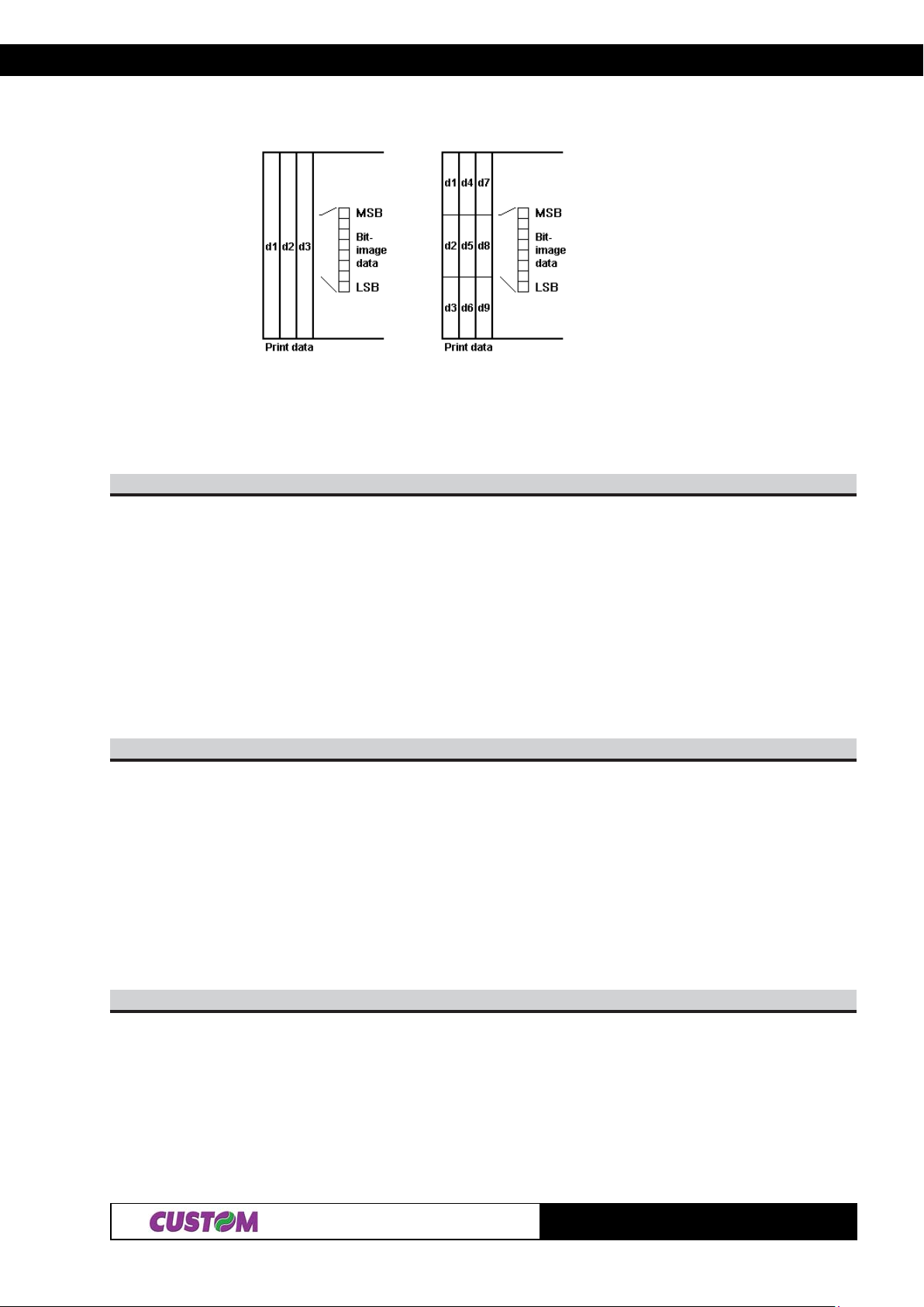
2. PRINTER FUNCTIONS
8 dot image 24 dot image
[Default]
[Reference]
[Example]
04$B1$
[Name] Inizialize the printer.
[Format] ASCII ESC @
Hex 1B 40
Decimal 27 64
[Description] Clears the data in the print buffer and resets the printer mode to the one that was in
effect when the power was turned on
[Notes] • Same as hardware reset
[Default]
[Reference]
[Example]
24$B1$
[Name] Select Font 1
[Format] ASCII ESC B
Hex 1B 42
Decimal 27 66
[Description] Select FONT 1
[Notes] • Setting remains until next set.
[Default] Set up from front keys.
[Reference] $1B $62
[Example]
34$B1$
[Name] Total cut
[Format] ASCII ESC C
Hex 1B 43
Decimal 27 67
[Description] This command enables cutter operation; if there is no cutter, a disabling flag is set and
any subsequent cutting commands will be ignored.
2-39
TG1260/2460
Page 57
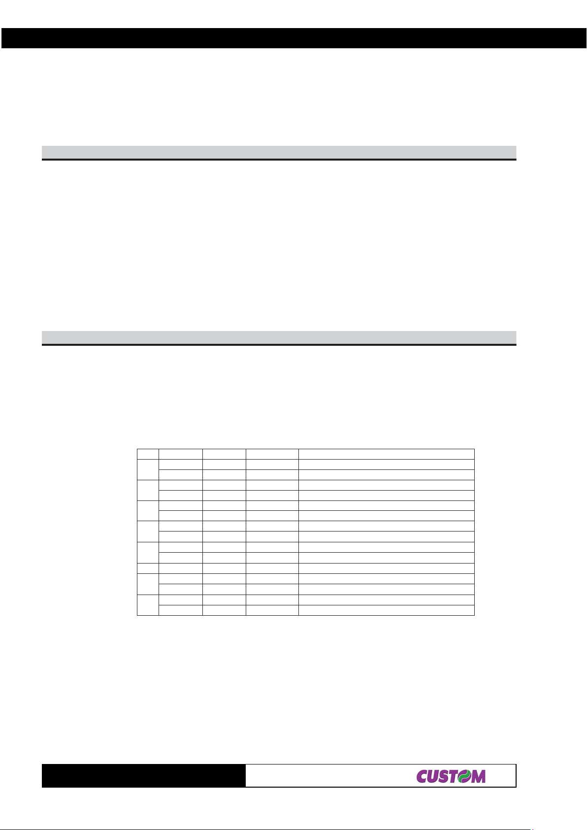
2. PRINTER FUNCTIONS
[Notes] • The printer waits until all the paper movement commands have been completed before
executing total cut
[Default]
[Reference]
[Example]
D0$]d[B4$B1$
[Name] Set the characters to transmit on pressing the Print key.
[Format] ASCII ESC K CR
Hex 1B 4B 0D
Decimal 27 75 13
[Description] Saves characters to transmit on pressing Print key.
“d” is the ASCII string to transmit, terminating with $0D. To deactivate this function,
transmit a $00.
[Notes] • The maximum number of characters to transmit is 24 (with $0D at the end).
[Default] d = 13
[Reference]
[Example]
74$B1$LdHd
[Name] Set default parameters.
[Format] ASCII dH dL ESC G
Hex dH dL 1B 47
Decimal dH dL 27 71
[Range] 0 ≤ dH, dL ≤ 255
[Description] Sets default parameters as indicated as follows :
tiBnO/ffOxeHlamiceDnuFnoitc
0
1
2
3
4
5ffO000 ffOotdexiF
6
7
ffO000 edomgnitnirpLAMRON
nO101 edomgnitnirpESREVER
ffO000 detucexednammocD0$
nO202 derongidnamm
ffO000 gnitnirplatnoziroH
nO404 gnitnirplacitreV
ffO000 gnitnirpderetnecetucexet'nseod
nO808 gnitnirpderetnecsetu
ffO000 tfelottnirpsngilA
nO0161thgirottnirpngilA
ffO000 gninilrednusetavitcaeD
nO0446gninilrednuset
ffO000 gnitnirpdlobsetavitcaeD
nO08821gnitnirpdlobsetavitcA
ocD0$
cexe
avitcA
[Notes] Setting is memorized in EEPROM.
[Default] Set up from front keys.
[Reference]
[Example] If dH = ‘4’ and dL = ‘D’ the value of d is 77 ($4D)
TG1260/2460
2-40
Page 58

2. PRINTER FUNCTIONS
D4$B1$LdHd
[Name] Set default parameters of print mode.
[Format] ASCII dH dL ESC M
Hex dH dL 1B 4D
Decimal dH dL 27 77
[Description] Sets the default parameters of print mode as indicated as follows :
$00 : small print
$01 : double width printing
$02 : double height printing
$03 : bold printing
[Notes] Setting is memorized in EEPROM.
[Default] Set up from front keys.
[Reference]
[Example] If dH = ‘A ’ and dL = ‘3’ the value of d is 163 ($A3)
E4$B1$
[Name] Set printing in NORMAL
[Format] ASCII ESC N
Hex 1B 4E
Decimal 27 78
[Description] Selects printing in NORMAL mode.
[Notes] • Setting remains until next set.
[Default] Set up from front keys.
[Reference] $1B $52
[Example]
25$B1$
[Name] Set printing in REVERSE
[Format] ASCII ESC R
Hex 1B 52
Decimal 27 82
[Description] Set printing in REVERSE mode.
[Notes] • Setting remains until next set
[Default] Set up from front keys.
[Reference] $1B $4E
[Example]
n65$B1$
[Name] Set print mode rotated by 90°.
[Format] ASCII ESC V n
Hex 1B 56 n
Decimal 27 86 n
[Range] 0 ≤ n ≤ 1
48 ≤ n ≤ 49
[Description] Enable / disable print mode rotated by 90°. n is used as follows :
2-41
TG1260/2460
Page 59
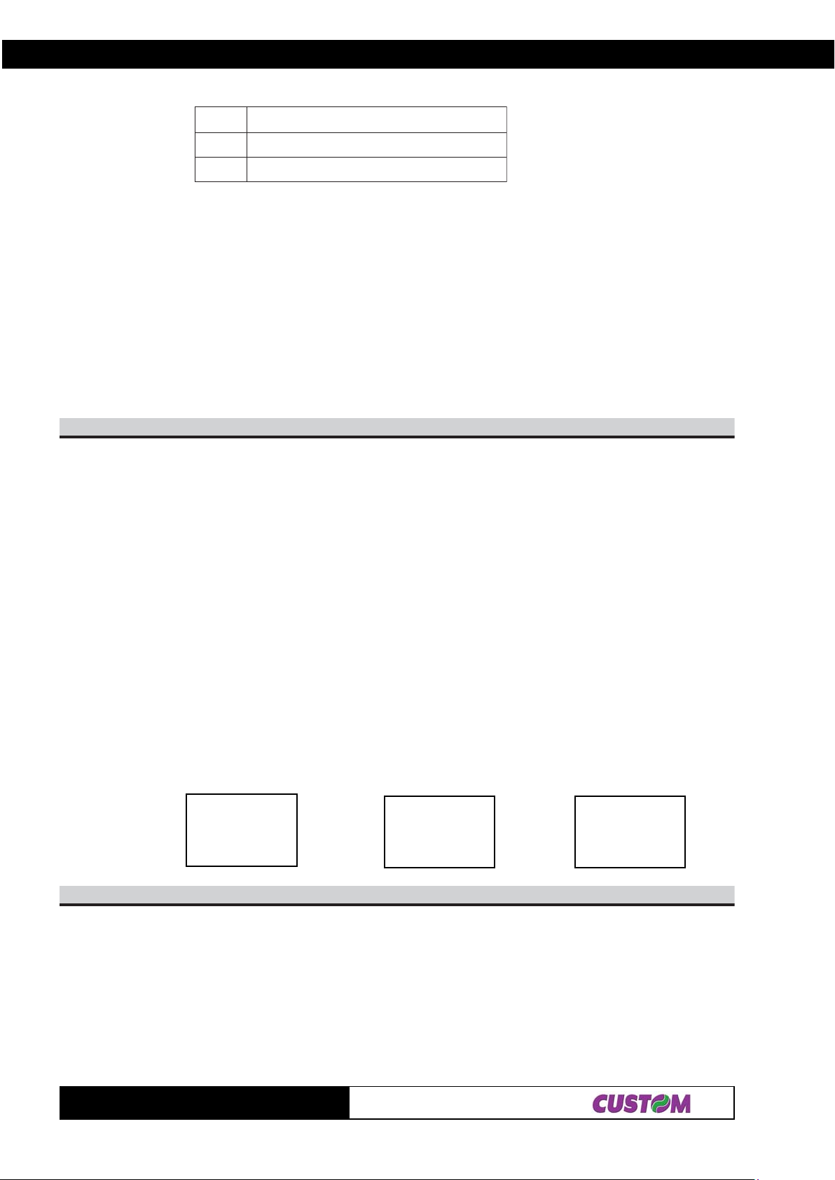
2. PRINTER FUNCTIONS
nnoitcnuF
84,0edomnoitator°09ffosnruT
94,1edomnoitator°09nosnruT
[Notes] • When underlined mode is turned on, the printer does not underline 90° rotated charac-
ters. All the same it’ s possible select the underline mode.
• Double-width and double-height commands in 90° rotation mode enlarge characters in
the opposite directions from double-height and double-width commands in normal
mode.
• This command is not available in Page mode.
• If this command is entered in Page mode, the printer all the same save the setting.
Default] n = 0
[Reference] $1B $21 , $1B $2D
[Example]
n16$B1$
[Name] Select justification
[Format] ASCII ESC a n
Hex 1B 61 n
Decimal 27 97 n
[Range] 0 ≤ n ≤ 2, 48 ≤ n ≤ 50
[Description] Aligns all the data in one line in the position specified. n selects the type of justification
as follows:
n Justification
0, 48 Left justification
1, 49 Centering
2, 50 Right justification
[Notes] • This command is only enabled if input at the beginning of the line.
• The lines are justified within the specified printing area.
• The spaces set by the command $1B $24 remain justified as per the previously set
mode.
[Default] n = 0
[Reference]
[Example] Left justification Centering Right justification
ABC
ABCD
ABCDE
26$B1$
[Name] Select FONT 2.
[Format] ASCII ESC b
Hex 1B 62
Decimal 27 98
[Description] Select FONT 2.
[Notes] • Setting remains until next set
TG1260/2460
ABC
ABCD
ABCDE
ABC
ABCD
ABCDE
2-42
Page 60

2. PRINTER FUNCTIONS
[Default] Set up from front keys.
[Reference] $1B $42
[Example]
D6$B1$
[Name] Read default parameters of print mode
[Format] ASCII ESC m
Hex 1B 6D
Decimal 27 109
[Description] Reads default parameters of print mode.
[Notes] See ESC M.
[Default] Set up from front keys.
[Reference] $1B $4D
[Example]
07$B1$
[Name] Read default parameters
[Format] ASCII ESC p
Hex 1B 70
Decimal 27 112
[Description] Reads default and “on line” parameters.
[Notes] See $1B $47.
[Default] Set up from front keys
[Reference] $1B $47
[Example]
27$B1$LaHa
[Name] Read EEPROM position.
[Format] ASCII aH aL ESC r
Hex aH aL 1B 72
Decimal aH aL 27 114
[Range] 0 ≤ a ≤ 63
‘0’ ≤ aH ≤ ‘9’, ‘A ’ ≤ aH ≤ ‘F’
‘0’ ≤ aL ≤ ‘9’, ‘A’ ≤ aL ≤ ‘F’
[Description] Reads the location addressed by a where:
aH is the most significant nibble, expressed in ASCII, of a
aL is the least significant nibble, expressed in ASCII, of a
[Notes]
[Default]
[Reference] $1B $77
[Example] T o read the position $12, transmit: $31 $32 $1B $72
The response will be the location value in hexadecimals expressed in two ASCII bytes.
2-43
TG1260/2460
Page 61
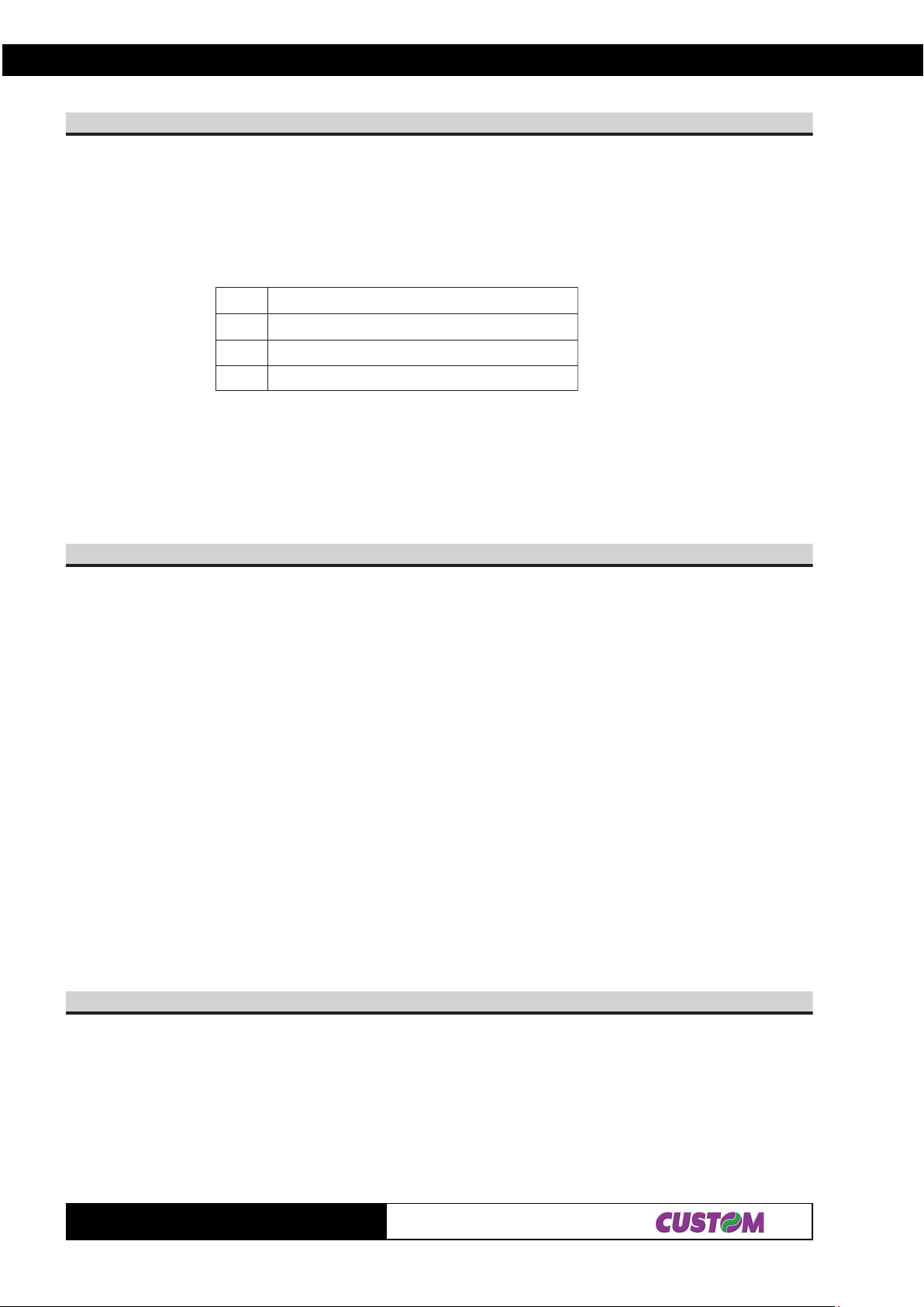
2. PRINTER FUNCTIONS
n47$B1$
[Name] Select the character code table.
[Format] ASCII ESC t n
Hex 1B 7 4 n
Decimal 27 116 n
[Range] n = 0, 19, 255
[Description] Selects a page n from the character code table, as follows:
negaP
0)]eporuEdradnatS,.A.S.U[734CP(0
91312noitisoptalobmysoruErof858CP(91
552ecapsegaP
[Note]
[Default] n = 0
[Reference] See character code table
[Example] For printing Euro symbol (•), the command sequence is:
$1B, $74, $13, $D5
77$B1$LdHdLaHa
[Name] Write EEPROM position.
[Format] ASCII aH aL dH dL ES C w
Hex aH aL dH dL 1B 77
Decimal aH aL dH dL 27 119
[Range] 0 ≤ a ≤ 63
‘0’ ≤ aH ≤ ‘9’, ‘A ’ ≤ aH ≤ ‘F’
‘0’ ≤ aL ≤ ‘9’, ‘A’ ≤ aL ≤ ‘F’
0 ≤ d ≤ 255
‘0’ ≤ dH ≤ ‘9’, ‘A ’ ≤ dH ≤ ‘F’
‘0’ ≤ dL ≤ ‘9’, ‘A’ ≤ dL ≤ ‘F’
[Description] Writes, at the location addressed by a, data dwhere:
aH is the most significant nibble, expressed in ASCII, of a
aL is the least significant nibble, expressed in ASCII, of a
dH is the most significant nibble, expressed in ASCII, of d
dL is the least significant nibble, expressed in ASCII, of d
[Notes]
[Default]
[Reference] $1B $72
[Example] T o write the value $34 in position $12, transmit: $31 $32 $33 $34 $1B $77
LyHyLxHxnAF$B1$
[Name] Print graphic bank ( 448
[Format] ASCII ESC { } n xH xL yH yL
Hex 1B FA n xH xL yH y L
Decimal 27 250 n xH xL yH yL
[Range] 1 ≤ n ≤ 2
0 ≤ xH, xL, yH, yL ≤ 255
[Description] Prints the graphics bank from flash or ram.
n selects the bank as follows:
TG1260/2460
× ×
× 1170 dots).
× ×
2-44
Page 62
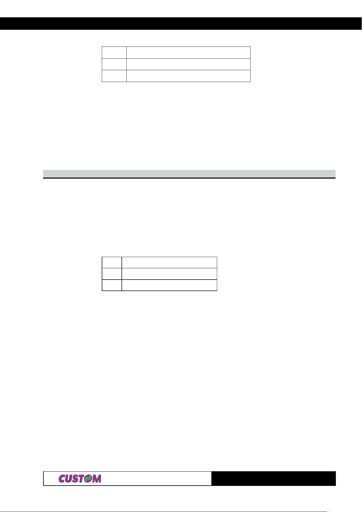
2. PRINTER FUNCTIONS
nnuFnoitc
1ftnirPhsal1ogolknab
22ogolknabhsalftnirP
xL + xH × 256 specifies the starting dot line ( 1 ÷ 1170 ).
yL + yH × 256 specifies the number of lines to print.
[Notes] • If (xL + (xH × 256)) > 1170 the printer does not execute the command.
• Se ( xL + ( xH × 256 ) + yL +( yH × 256 ))> 1170 the printer only prints 1170 - xL + ( xH
× 256 ) +1 dotlines.
[Default]
[Reference]
[Example] T o print logo 1 from flash bank dotline 100 to dotline 299, send:
$1B $FA $01 $00 $64 $00 $C7
HnLnFF$B1$
[Name] Receive and store logos in flash.
[Format] ASCII ESC { } m nL nH d0 dn
Hex 1B FF m n L nH d0 dn
Decimal 27 255 m nL nH d0 dn
[Range] 0 ≤ nL, nH ≤ 255 1 ≤ m ≤ 20 ≤ d0, dn ≤ 255
[Description] • Received [nL + (nH x 256)] x 2 bytes and store in the flash.
• If [nL + (nH x 256)] exceeds 32768, the data following will be processed as normal
data.
• Saved the graphics bank from flash. m selects the bank as follows:
mnoitcnuF
11knabhsalfotniepytogolevaS
22knabhsalfotniepytogolevaS
• d0, dn = value of bit stream image
[Default]
[Reference]
[Example] T o store the logotype indicated below ,into flash bank 2, necessity execute the follows
operation
1)Define the image dimensions.
The width of image is 448 horizontal pixel ; the height maximun of image is 1170 vertical
pixel.
2) Calculate the number of bytes to send as (height pix*width pix)/16.
Bytes number in example is 448 x 1 170/16=32760 in exadecimal resulting =
7FF8.
3) Bit stream image conversion.
In the following figure is reproduced the logotype enlargement in the zone indicated by
the arrow to define d0...dn
2-45
TG1260/2460
Page 63
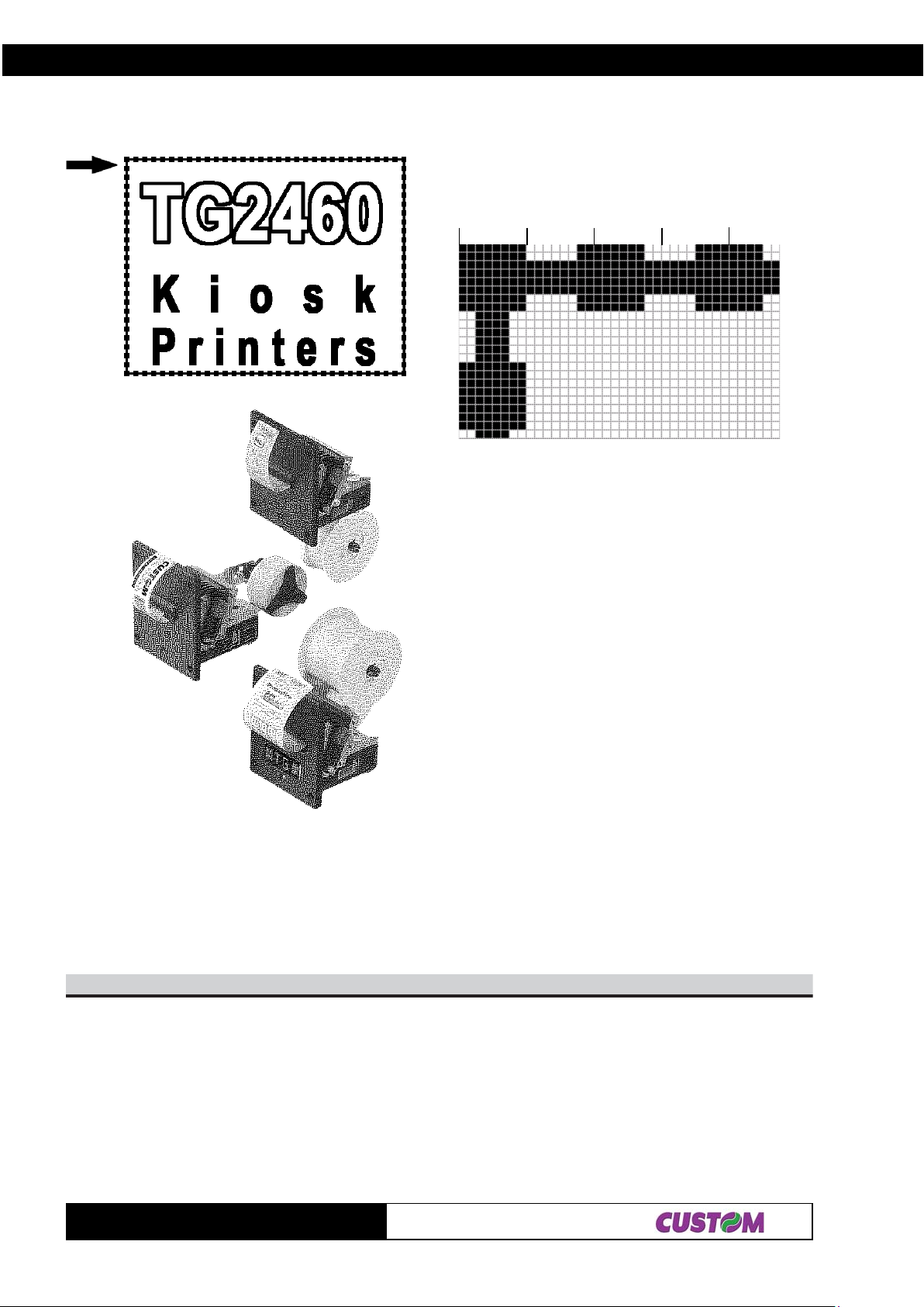
2. PRINTER FUNCTIONS
d0 d1 d2 d3
In this example; d0=FF; d1=03; d2=FC; d3=0F
Then send this command to the printer
0x1B 0xFF 0x02 0xF8 0x7F 0xFF 0 x 03 0xFC 0x0F ...
N. logo Dimension
43$0C$C1$
[Name] Total cut and automatic paper moving back.
[Format] ASCII FS { } 4
Hex 1C C0 34
Decimal 28 192 52
[Description] This command enables cutter operation and executes a total cut and automatic paper
moving back; if there is no cutter, a disabling flag is set any subsequent cutting
commands will be ignored.
[Notes] • The printer waits until all the paper movement commands have been completed
before executing total cut
TG1260/2460
2-46
Page 64

2. PRINTER FUNCTIONS
[Default]
[Reference]
[Example]
C0$D1$
[Name] Print the buffer contents.
[Format] ASCII GS FF
Hex 1D 0C
Decimal 29 12
[Description] Prints contents of buffer characters and executes a line feed.
Sets the printing start position at left margin.
[Notes]
[Default]
[Reference] $0A
[Example]
A3$D1$
[Name] Start / end macro definition.
[Format] ASC II GS :
Hex 1D 3A
Decimal 29 58
[Description] St art s or ends macro definition.
[Notes] • Macro definition starts when this command is received during normal operation.
• When the command $1D $5E is received during macro definition, the printer ends the
macro definitions and clears all definitions.
• Macro not defined when the power is turned on.
• The defined contents of the macro are not cleared by the command $1B $40.
Therefore, $1B $40 can be included in the contents of the macro definitions.
• If the printer receives the command $1D $3A again immediately after previously
receiving $1D $3A, the printer remains in the macro undefined state.
• The contents of the macro can be defined up to 1024 bytes. If the macro definition
exceeds 1024 bytes, the excess data is not not stored.
[Default]
[Reference] $1D $5E
[Example]
mn03$34$D1$
[Name] Set counter print mode.
[Format] ASCII GS C 0 n m
Hex 1D 43 30 n m
Decimal 29 67 48 n m
[Range] 0 ≤ n ≤ 5
m = 0, 1, 2, 48, 49, 50
[Description] Selects a print mode for the serial number counter .
• n specifies the number of digits to be printed as follows:
when n = 0, the printer prints the actual digits indicated by the number value.
when n = from 1 to 5, this command sets the number of digits to be printed.
• m specifies the printing position within the entire range of printed digits, as follows:
2-47
TG1260/2460
Page 65
2. PRINTER FUNCTIONS
mP deificepsesohtnahtrewolstigidfognissecorP
84.0noitacifitsujthgiRAtfelotsecapsdd..
94.1noitacifitsujthgiRAdd.tfel
05.2noitacifitsujtfeLA.thgirotsecapsdd
[Notes] • if n or m is outside the defined range, the previously set print mode is not changed.
• If n = 0, m has no meaning.
[Default] n = 0, m = 0
[Reference] $1D $43 $31, $1D $43 $32, $1D $43 $3B, $1D $63
[Example] n = 3, m = 0 n = 3, m = 1 n = 3, m=2
1 001 1
indicates a space
ot’0‘
rnHbLbHaLa13$34$D1$
[Name] Select count mode (A).
[Format] ASCII GS C 1 a L aH bL bH n r
Hex 1D 43 31 aL aH bL bH n r
Decimal 29 67 49 aL aH bL bH n r
[Range] 0 ≤ aL, aH ≤ 255
0 ≤ bL, bH ≤ 255
0 ≤ n, r ≤ 255
[Description] Selects a count mode for the serial number counter.
• aL, aH o bL, bH specify the counter range.
• n specify the stepping amount when counting up or down.
• r indicates the repetition number when the counter value is fixed.
[Notes] • Count-up mode is specified when:
[aL + (aH × 256)] < [bL + (bH × 256)] and n ≠ 0 and r ≠ 0
• Count-down mode is specified when:
[aL + (aH × 256)] > [bL + (bH × 256)] and n ≠ 0 and r ≠ 0
• Counting stops when:
[aL + (aH × 256)] = [bL + (bH × 256)] or n = 0 or r = 0
• In setting count-up mode, the minimum value of the counter is [aL + (aH × 256)] and
the maximum value is [bL + (bH × 256)]. If counting up reaches a value exceeding the
maximum, it is resumed with the minimum value.
• In setting count-down mode, the maximum value of the counter is [aL + (aH × 256)]
and the minimum value is [bL + (bH × 256)]. If counting down reaches a value less than
minimum, it is resumed with the maximum value.
• When the command is executed, the internal count that indicates the repetition
number specified by r is cleared.
[Default] aL = 1, aH = 0, bL = 255, bH = 255, n = 1, r = 1
[Reference] $1D $43 $30, $1D $43 $32, $1D $43 $3B, $1D $63
[Example]
HnLn23$34$D1$
[Name] Set counter.
[Format] ASCII GS C 2 nL nH
Hex 1D 43 32 nL nH
Decimal 29 67 50 nL nH
TG1260/2460
2-48
Page 66

2. PRINTER FUNCTIONS
[Range] 0 ≤ nL, nH ≤ 255
[Description] Sets the serial number counter value.
• nL and nH determine the value of the serial number counter set by [nL + (nH × 256)].
[Notes] • In count-up mode, if the counter value specified by this command goes out of the
counter operation range specified by GS C 1 or GS C ;, it is forced to convert to the
minimum value by GS c.
• In count-down mode, if the counter value specified by this command goes out of the
counter operation range specified by GS C 1or GS C ;, it is forced to convert to the
maximum value by GS c.
[Default] nL = 1, nH = 0
[Reference] $1D $43 $30, $1D $43 $31, $1D $43 $3B, $1D $63
[Example]
B3$csB3$rsB3$nsB3$bsB3$asB3$34$D1$
[Name] Select count mode.
[Format] ASCII GS C ; sa ; sb ; sn ; sr ; sc ;
Hex 1D 43 3B sa 3B sb 3B sn 3B sr 3B sc 3B
Decimal 29 67 59 sa 59 sb 59 sn 59 sr 59 sc 59
[Range] 0 ≤ sa, sb, sc ≤ 65535
0 ≤ sn, sr ≤ 255
These values are all character strings.
[Description] Selects a count mode for the serial number counter and specifies the value of the
counter.
• sa, sb, sn, sr and sc are all displayed in ASCII characters using the codes from ‘O’ to
‘9’.
• sa and sb specify the counter range.
• sn indicates the stepping amount for counting up or down.
• sr indicates the repetition number with the counter value fixed.
• sc indicates the counter value.
[Notes] • Count-up mode is specified when:
sa < sb and sn ≠ 0 and sr ≠ 0
• Count-down mode is specified when:
sa > sb and sn ≠ 0 and sr ≠ 0
• Counting stops when:
sa = sb or sn = 0 or sr = 0
• In setting count-up mode, the minimum value of the counter is sa and the maximum is
sb. If counting up reaches a value exceeding the maximum, it is resumed with the
minimum value. If the counter value set by sc is outside the counter operation range,
the counter value is forced to convert to the minimum value by executing $1D $63.
• In setting count-down mode, the maximum value of the counter is sa and the
minimum value is sb. If counting down reaches a value less than the minimum, it is
resumed with the maximum value. If the counter value set by sc is outside the counter
operation range, the counter value is forced to convert to the maximum value by
executing $1D $63.
• Parameters sa to sc can be omitted. If omitted, these values remain unchanged.
• Parameters sa to sc must not contain characters, with the exception of those from ‘0’
to ‘9’.
[Default] sa = 1, sb = 65535, sn = 1, sr = 1, sc = 1
[Reference] $1D $43 $30, $1D $43 $32, $1D $43 $31, $1D $63
[Example]
2-49
TG1260/2460
Page 67
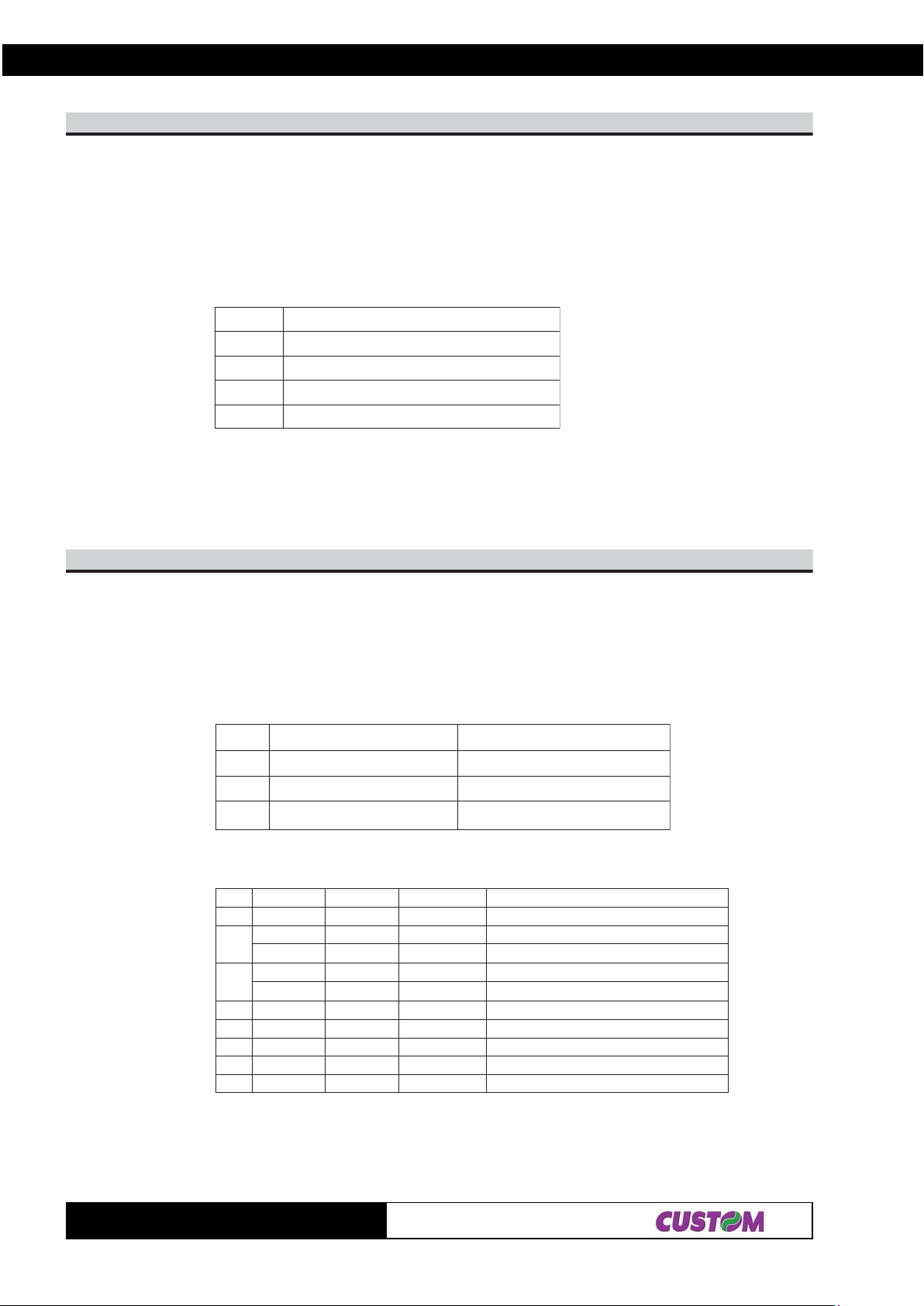
2. PRINTER FUNCTIONS
n84$D1$
[Name] Select printing position of Human Readable Interpretation ( HRI )
[Format] ASCII GS H n
Hex 1D 48 n
Decimal 29 72 n
[Range] 0 ≤ n ≤ 3, 48 ≤ n ≤ 51
[Description] Selects the printing position of HRI characters when printing bar code. n selects the
printing position as follows:
nnuFnoitc
84,0oNdetnirpt
94,1ehtevobA.edocrab
05,2ehthtaenrednU.edocrab
15,3ehthtaenrednudnaevobahtoB.edocrab
[[Notes] • HRI characters are printed using the font specified by the command GS f.
[Default] n = 0
[Reference] $1D $66, $1D $6B
[Example]
n94$D1$
[Name] Transmit printer ID.
[Format] ASCII GS I n
Hex 1D 49 n
Decimal 29 73 n
[Range] 1 ≤ n ≤ 3, 49 ≤ n ≤ 51
[Description] Transmits the printer ID specified by n as follows:
nretnirPDInoitacificepS
94,1noitacifitnediedomretnirP)0642GT(D6$
05,2noitacifitnedinoitcnuFwolebelbateeS
15,3MORn
oitacifitnedinoisrevDnosdnepe)rahc4(noisrevMOR
n = 2, Identification Function
tiBnO/ffOxeHlamiceDnuFnoitc
0ffO000 sedocretcarahcetyb-2detroppusnoN
1
2
3- - - DEVRESER
4ffO000 0tadexiF
5- - - DEVRESER
6- - - DEVRESER
7ffO000 0tadexiF
ffO000 deilppustonrettucotuA
nO202 deilppusrettucotu
ffO000 lebaltuohtiwrepaplamrehT
nO404 lebalhtiwrepaplamrehT
A
[Notes] • When the DTR/DSR control is selected, the printer only transmits 1 byte (Printer
identification) after it has been given confirmation that the host is ready to receive data.
If the host is not ready , the printer waits until it is.
• When the XON/XOFF control is selected, the printer only transmits 1 byte (Printer
TG1260/2460
2-50
Page 68

2. PRINTER FUNCTIONS
identification) if it has not been given confirmation that the host is ready to receive data.
• This command is carried out once the data has been processed in the reception
buffer . There may therefore be a delay between the moment in which the command is
received and that in which the data is transmitted, depending on the status of the
reception buffer .
[Default]
[Reference]
[Example]
yx05$D1$
[Name] Set horizontal and vertical motion units.
[Format] ASCII GS P x y
Hex 1D 50 x y
Decimal 29 80 x y
[Range] x = 100, 200
y = 100, 200
[Description] Sets the horizontal and vertical motion units at 1/x inches and 1/y inches, respectively .
When x is set at 0, the default setting value is used.
When y is set at 0, the default setting value is used.
[Notes] • This command set the ESC/POS emulation and initialize the default values again.
• The horizontal direction is perpendicular to the paper feed direction.
• This command does not affect the previously specified values.
• The calculated result from combining this command with others is truncated to the
minimum value of the mechanical pitch or an exact multiple of that value.
[Default] x = 200, y = 200
[Reference] $1B $24
[Example]
mtrE5$D1$
[Name] Execute macro.
[Format] ASCII GS ^ r t m
Hex 1D 5E r t m
Decimal 29 94 r t m
[Range] 0 ≤ r, t ≤ 255
0 ≤ m ≤ 1
[Description] Executes a macro.
• rspecifies the number of times to execute the macro.
• t specifies the waiting time for executing the macro.
The waiting time is t × 100 msec. for every macro execution.
• m specifies macro executing mode:
When the LSB of m = 0, the macro executes r times continuously at the interval
specified t.
When the LSB of m = 1, after waiting for the period specified by t, the LED indicator
blinks and the printer waits for the FEED button to be pressed. After the button is
pressed, the printer executes the macro once. The printer repeats the operation rtimes.
[Notes] • This command lasts for a period of (t × 100 msec.) after a macro is executed by t.
• If this command is received while a macro is being defined, the macro definition is
aborted and the definitions cleared.
• If the macro is not defined or if r is 0, nothing happens.
2-51
TG1260/2460
Page 69

2. PRINTER FUNCTIONS
• When the macro is executed by pressing the FEED button ( m = 1), the paper can not
be fed by using the FEED button.
[Default]
[Reference] $1D $3A
[Example]
36$D1$
[Name] Print counter.
[Format] ASCII GS c
Hex 1D 63
Decimal 29 99
[Description] Sets the serial counter value in the print buffer and increments or decrements the
counter value.
[Notes] • After setting the current counter value in the print buffer as print data (a character
string), the printer counts up or down based on the count mode set. The counter value
in the print buffer is printed when the printer receives a print command or is in the buffer
full state.
• The counter print mode is set by $1D $43 $30.
• The counter mode is set by $1D $43 $31 or $1D $43 $3B.
• In count-up mode, if the counter value set by this command goes out of the counter
operation range set by $1D $43 $31 or $1D $43 $3B, it is forced to convert to the
minimum value.
• In count-down mode, if the counter value set by this command goes out of the counter
operation range set by $1D $43 $31 or $1D $43 $3B, it is forced to convert to the
maximum value.
[Default]
[Reference] $1D $43 $30, $1D $43 $31, $1D $43 $32, $1D $43 $3B
[Example]
n66$D1$
[Name] Select font for HRI characters.
[Format] ASCII GS f n
Hex 1D 66 n
Decimal 29 102 n
[Range] n = 0, 1, 48, 49
[Description] Selects a font for the HRI characters used when printing a bar code.
n selects a font from the following table:
ntnoF
84,0)42x41(ATNOF
94,1)42x01(BTNOF
[Notes] The HRI characters are printed at the position specified by the command GS H.
[Default] n = 0
[Reference] $1D $48, $1D $6B
[Example]
TG1260/2460
2-52
Page 70
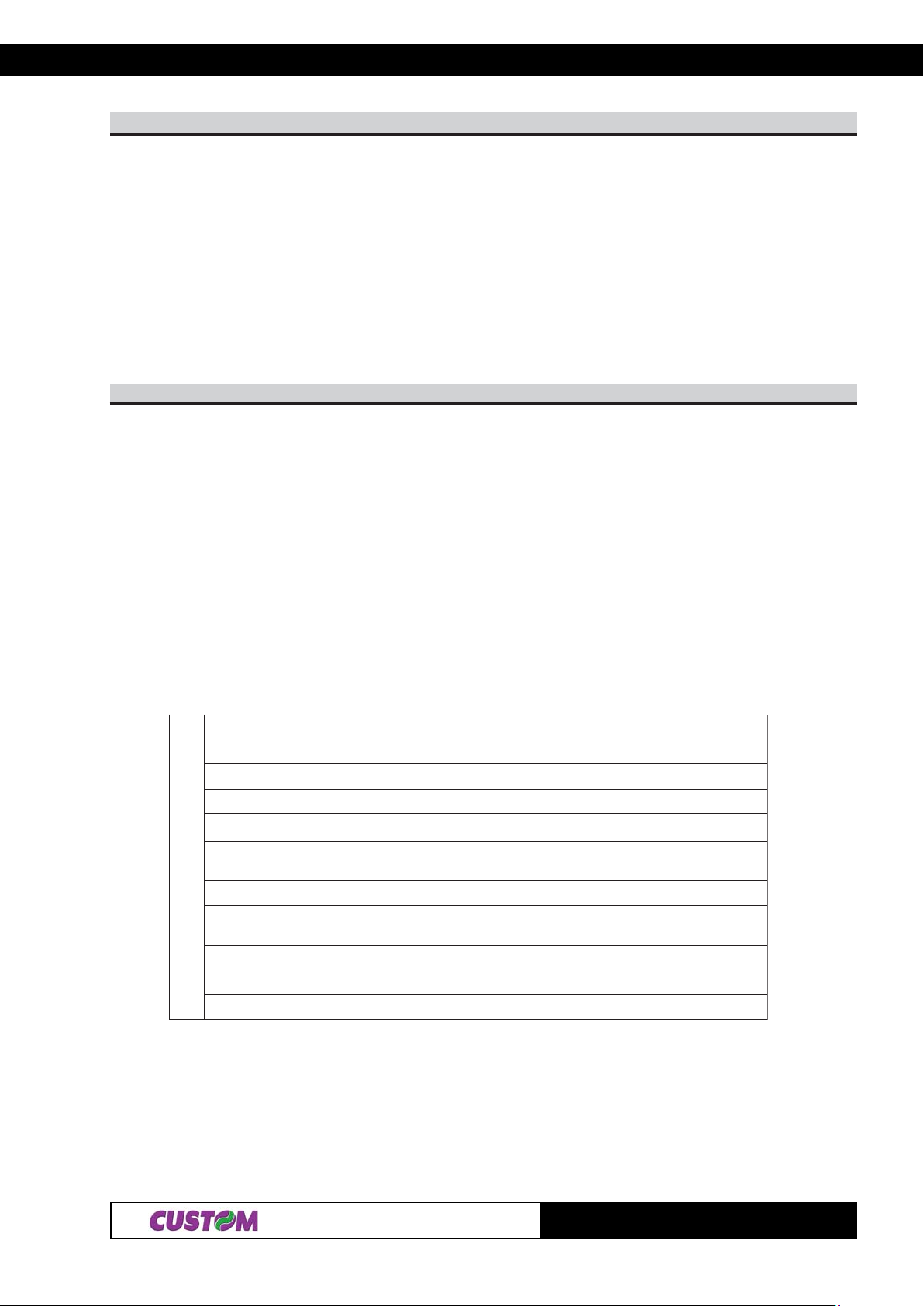
2. PRINTER FUNCTIONS
n86$D1$
[Name] Set bar code height
[Format] ASCII GS h n
Hex 1D 68 n
Decimal 29 104 n
[Range] 1 ≤ n ≤ 255
[Description] Sets the height of the bar code. n specifies the number of dots in the vertical direction.
[Notes]
[Default] n = 96 ( 12 mm )
[Reference] $1D $6B
[Example]
00$]kd...1d[mB6$D1$ ]nd...1d[nmB6$D1$
[Name] Print bar code.
[Format] ASCII GS k m NUL
Hex 1D 6B m 00
Decimal 29 107 m 0
ASCII GS k m n
Hex 1D 6B m n
Decimal 29 107 m n
[Range] 0 ≤ m ≤ 6
65 ≤ m ≤ 73
[Description] Selects a bar code system and prints the bar code. m selects a bar code sys
mB metsysedocrasretcarahcforebmuNskrameR
0A-CPU11 ≤ k ≤ 2184 ≤ d ≤ 75
1E-CPU11 ≤ k ≤ 2184 ≤ d ≤ 75
2)NAJ(31NAE21 ≤ k ≤ 3184 ≤ d ≤ 75
3)NAJ(8NAE7
493EDOC1≤ k
5FTI1≤ (krebmunneve) 84 ≤ d ≤ 75
6RABADOC1≤ k
739EDOC1≤ k ≤ 5521≤ d ≤ 721
8821EDOC2≤ k ≤ 5521≤ d ≤ 721
0223EDOC8≤ k ≤ 984 ≤ d ≤ 75
≤ k ≤ 884 ≤ d ≤ 75
84 ≤ d ≤ 56,75 ≤ d ≤ ,73,63,23,09
84 ≤ d ≤ 56,75 ≤ 1d ≤ ,34
74,64,54,34
,63,86
85,74,64,54
2-53
TG1260/2460
Page 71
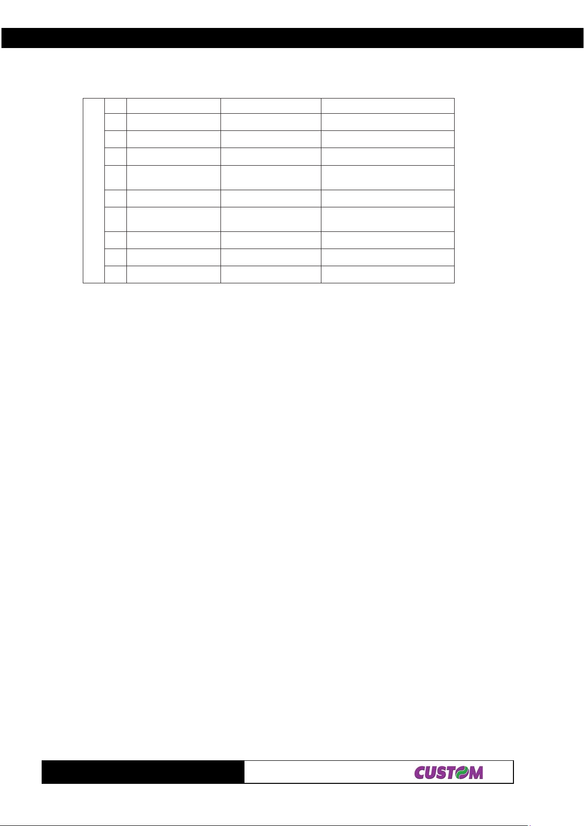
2. PRINTER FUNCTIONS
56A-CPU11 ≤ n ≤ 2184 ≤ d ≤ 75
66E-CPU11 ≤ n ≤ 2184 ≤ d ≤ 75
76)NAJ(31NAE21 ≤ n ≤ 3184 ≤ d ≤ 75
86)NAJ(8NAE7≤ n ≤ 884 ≤ d ≤ 75
9693EDOC1≤ n ≤ 552
07FTI1≤ n ≤ 55284 ≤ d ≤ 75
84 ≤ d ≤ 56,
17RABADOC1≤ n ≤ 552
2739EDOC1≤ n
37821EDOC2≤ n ≤ 5520≤ d ≤ 721
0923EDOC8≤ n ≤ 984 ≤ d ≤ 75
≤ 5520≤ d ≤ 721
[Notes] • If d is outside the specified range, the printer prints the following message: “BAR CODE
GENERA TOR NON OK !” and processes the following data as normal data.
• If the horizontal size exceeds the printing area, the printer only feeds the paper .
• This command feeds as much paper as is required to print the bar code.
• Af ter printing the bar code, this command sets the print position at the beginning of the
line.
• This command is not affected by print modes (bold, double strike, underline or
character size), with the exception of upside-down mode and justification.
[Notes for ] • This command ends with a $00 code.
• When the bar code used is UPC-A or UPC-E, the printer prints the bar code data after
receiving 1 1 (without check digit) or 12 ( with check digit) byte bar code dat a.
• When the bar code system used is EAN13, the printer prints the bar code after
receiving 12 (without check digit) or 13 (with check digit) byte bar code data.
• When the system used is EAN8, the printer prints the bar code after receiving 7
(without check digit) or 8 (with check digit) byte bar code data.
• The number of data for ITF bar code must be even. When an odd number of data is
input, the printer ignores the last received data.
[Note for ] • If n is outside the specified range, the printer stops command processing and
process the following data as normal data.
When to use
CODE93: • The printer prints an HRI character ( o ) as a start character at the beginning of the
HRIcharacter string.
• The printer prints an HRI character ( o ) as a stop character at the end of the HRI
character string.
• The printer prints an HRI character ( n ) as a control character ( $00 to $1F and $7F).
When to use
CODE128: • When using the CODE128 in this printer , take the following point s into account for data
transmission:
• The top of the bar code data string must be a code set selection character(CODE A ,
CODE B or CODE C) which selects the first code set.
• Special characters are defined by combining two characters “{“ and one character.
The ASCII character “}” is defined by transmitting “{“ twice consecutively.
75 ≤ d ≤ ,73,63,23,09
74,64,54,34
84 ≤ d ≤ 56,75 ≤ 1d ≤ ,34,63,86
85,74,64,54
TG1260/2460
2-54
Page 72
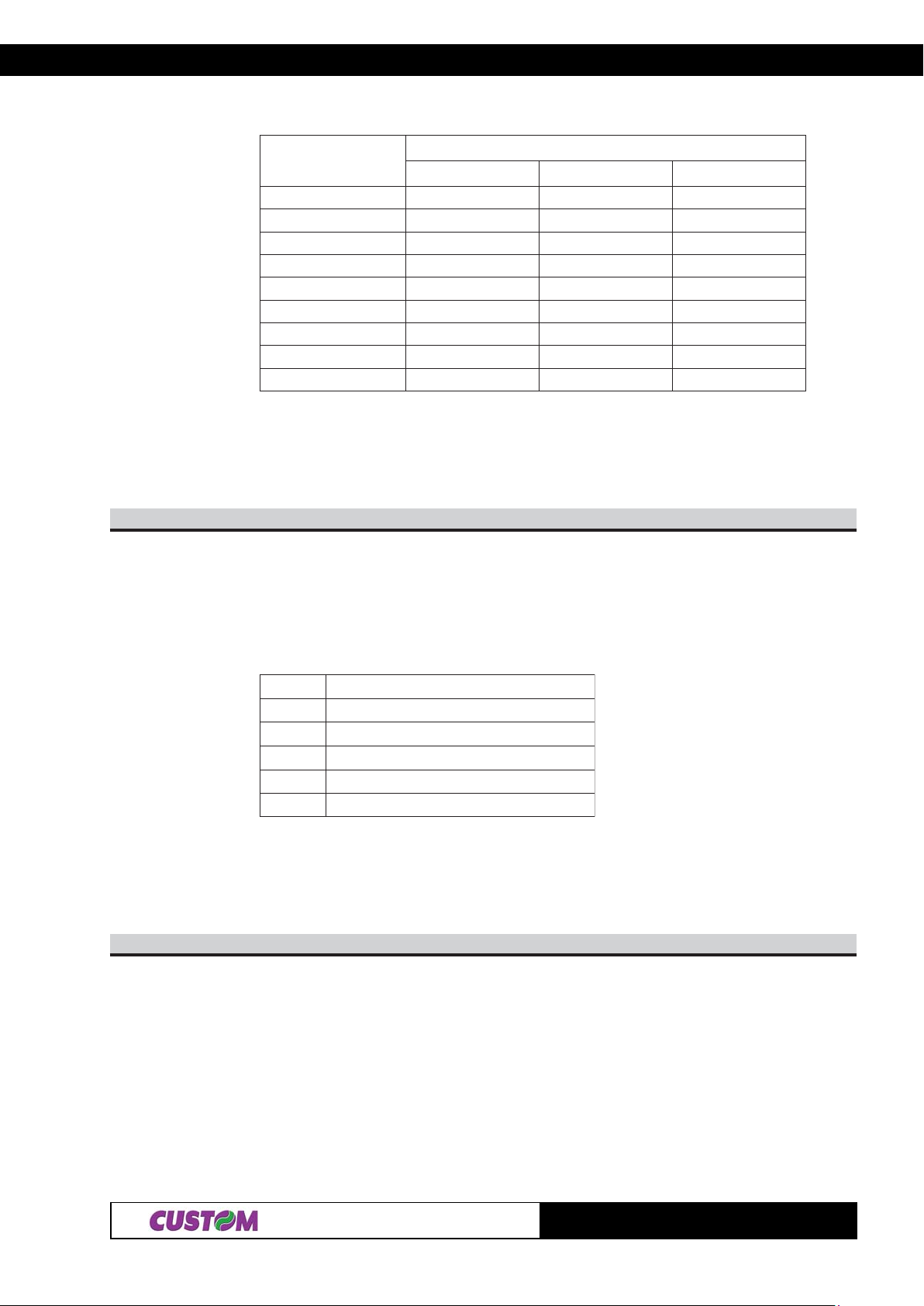
2. PRINTER FUNCTIONS
retcarahccificepS
IICSAxeHlamiceD
TFIHSS{35,B738.321
AEDOCA{14,B756.321
BEDOCB{24,B766.321
CEDOCC{34,B77
1CNF1{13,B794.321
2CNF2{23,B705.321
3CNF3{33,B715.321
4CNF4{43,B725.321
'{'{{B7,B7321.321
noissimsnartataD
6.321
[Default]
[Reference] $1D $48, $1D $66, $1D $68, $1D $77
[Example]
n77$D1$
[Name] Set bar code width.
[Format] ASCII GS w n
Hex 1D 77 n
Decimal 29 119 n
[Range] 2 ≤ n ≤ 6
[Description] Sets the horizontal size of the bar code. n specifies the bar code width as follows:
nhtdiweludoM)mm(
252.0
3573.0
45.0
5526.0
657.0
[Notes]
[Default] n = 3
[Reference] $1D $6B
[Example]
nC7$D1$
[Name] Set printing density.
[Format] ASCII GS { } n
Hex 1D 7 C n
Decimal 29 124 n
[Range] 0 ≤ n ≤ 4, 48 ≤ n ≤ 52
2-55
TG1260/2460
Page 73
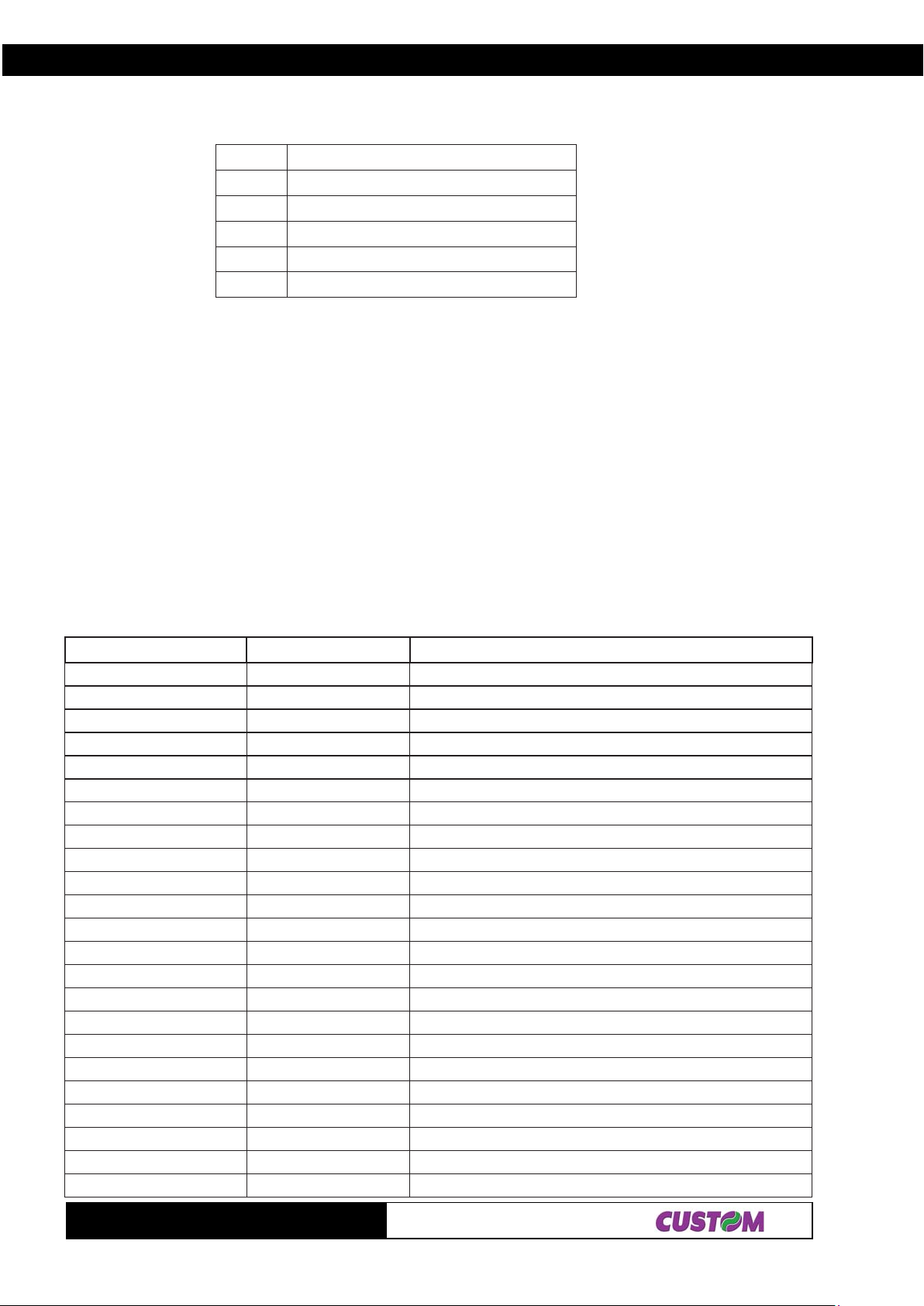
2. PRINTER FUNCTIONS
[Description] Sets the printing density. n specifies the printing density as follows:
nytisnedgnitnirP
84,0thgilyreV
94,1thgiL
05,2lamroN
15,3kraD
25,4kradyreV
[Notes] • The printing density is cleared at default value when the printer is reset or the power is
turned off.
[Default] n = 2
[Reference]
[Example]
2.1.3 CBM iDP560RS Emulation
The following table lists all the commands for function management in CBM iDP560RS Emulation. The
commands can be transmitted to the printer at any moment, but they will only be carried out when the commands
previously sent have been executed. There are no priority commands; all commands are carried out when the
circular buffer is free to do. to
COMMAND T ABLE
(Tab.2.3)
.moCXEH.moCIICSAnoitpircseD
00$LUNsretcarahcllamshtiwgnitnirP
10$HOSsretcarahchtdiwelbuodhtiwgnitnirP
20$XTSsret
carahcthgiehelbuodhtiwgnitnirP
30$XTEsretcarahcdednapxehtiwgnitnirP
40$TOEsretcarahcllamshtiwgnitnirP
A0$FLdee
fenildnatnirP
C0$FFgnitnirpretfadeefmroftuoseirraC
D0$RCnruteregairracdnatnirP
E0$OS)SRsaemas(noitangisedretca
rahcdevorpmI
F0$IS)SUsaemas(noitangisedretcarahcdradnatS
11$1CD)ENILNO(etatsTCELESretnirpehtsekaM
31$3CD)ENILF
FO(etatsTCELESEDretnirpehtsekaM
81$NACreffubehtniatadtnirpehtsraelC
E1$SR)enileno(noitangisedretcarahcdecna
hnE
F1$SUnoitangisedretcarahcdradnatS
13$B1$1CSEgnicapsenilmm3
23$B1$2CSEgnicapsenilmm5.5
04$B1$@CSEretnirpezilai
tinI
)n(34$B1$nCCSEgnittamrofegapdnanoitangisedhtgnelegaP
)2n1n(B4$B1$2n1nKCSEedomtnirpcihparG
F4$B1$OCSEffogn
ittamrofegaP
96$B1$iCSEtuclatoT
LyHyLxHxnAF$B1$LyHyLxHxn·CSEknabcihpargtnirP
TG1260/2460
2-56
Page 74
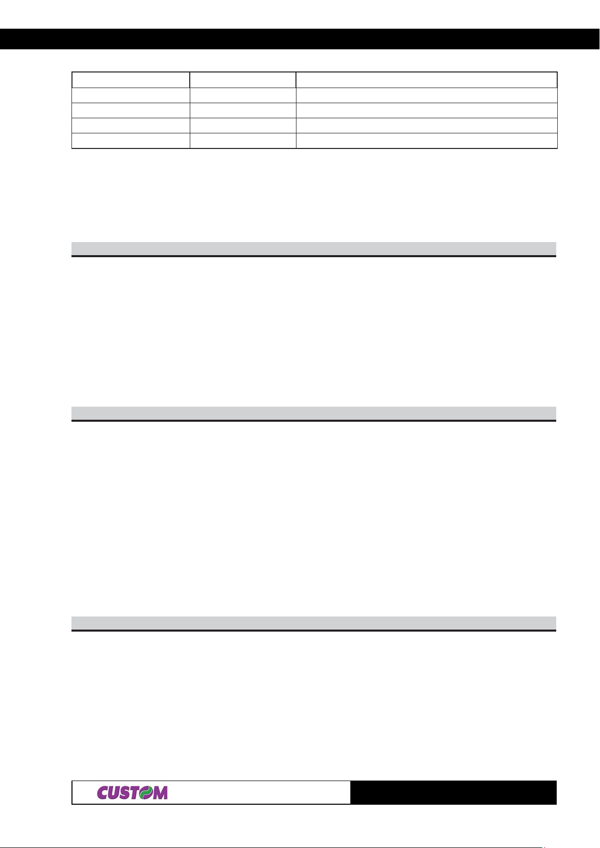
2. PRINTER FUNCTIONS
.moCXEH.moCIICSAnoitpircseD
43$0C$C1$4}{SFkcabgnivomrepapcitamotuadnatuclatoT
)n(94$D1$nISGDIretnirptimsnarT
x05$D1$yxPSGtinunoitomlacitrevdnalatnozirohteS
y
)n(C7$D1$n}{SGytisnedgnitnirpteS
NOTE: in “Note” column where the model is not specified, the command is valid for all models.
The following pages provide a more detailed description of each command.
00$
[Name] Print with small character
[Format] ASCII NUL
Hex 00
Decimal 0
[Description] Character printing is executed in small format (normal)
[Notes] • Setting remains until next set
[Default] Set up from front keys
[Reference] $1E, $1F , $0F, $0E, $01, $02, $03, $04
[Example]
10$
[Name] Printing with double width character
[Format] ASCII SOH
Hex 01
Decimal 1
[Description] Printing of the character is executed in double width format
[Notes] • Setting remains until next set
[Default] Set up from front keys
[Reference] $00, $02, $03, $04
[Example]
20$
[Name] Printing in double height character
[Format] ASCII STX
Hex 02
Decimal 2
[Description] Printing of the character is executed in double height format
[Notes] • Setting remains until next set
[Default] Set up from front keys
[Reference] $00, $01, $03, $04, $0E, $0F , $1E, $1F
[Example]
2-57
TG1260/2460
Page 75

2. PRINTER FUNCTIONS
H30
[[Name] Printing with expanded character
[Format] ASCII E XT
Hex 03
Decimal 3
[Description] Printing of the character is executed in expanded format
[Notes] • Setting remains until next set
[Default] Set up from front keys
[Reference] $00, $01, $02, $04, $0E, $0F , $1E, $1F
[Example]
H40
[Name] Print with small character
[Format] ASCII EOT
Hex 04
Decimal 4
[Description] Character printing is executed in small format (normal)
[Notes] • Setting remains until next set
[Default] Set up from front keys
[Reference] $00, $01, $02, $03, $0E, $0F , $1E, $1F
[Example]
A0$
[Name] Print and line feed
[Format] ASCII LF
Hex 0A
Decimal 10
[Description] Prints the data in the buffer and feeds one line, based on the current line spacing.
[Notes] This command sets the print position at the beginning of the line.
[Default]
[Reference] $1B $31, $1B $32
[Example]
C0$
[Name] Carries out form feed after printing.
[Format] ASCII FF
Hex 0A
Decimal 10
[Description] Prints the data in the buffer and feeds in accordance with the page length specified by
the command ESC C n.
[Notes] This command sets the print position at the beginning of the line.
[Default]
[Reference] $1B $43
[Example]
TG1260/2460
2-58
Page 76

2. PRINTER FUNCTIONS
D0$
[Name] Print and line feed
[Format] ASCII CR
Hex 0 D
Decimal 13
[Description] When autofeed is “$0D enabled”, this command functions in the same way as $0A,
otherwise, it is ignored.
[Notes] This command sets the print position at the beginning of the line.
[Default] See the “autofeed” parameter from Setup.
[Reference] $0A
[Example]
E0$
[Name] Improved character designation (same as $1E)
[Format] ASCII SO
Hex 0E
Decimal 14
[Description] Printing of the character is executed in expanded format.
[Notes] • The command SO is automatically launched after printing.
• Same as $1E
[Default] Set up from front keys
[Reference] $01, $02, $03, $04, $0F , $1E, $1F
[Example]
F0$
[Name] Standard character designation (same as $1F)
[Format] ASCII SI
Hex 0F
Decimal 15
[Description] Printing of the character is executed in small format
(normal).
[Notes] • Same as $1F
[Default] Set up from front keys
[Reference] $01, $02, $03, $04, $0E, $1E, $1F
[Example]
11$
[Name] Places the printer ON LINE.
[Format] ASCII DC1
Hex 11
Decimal 17
[Description] Places the printer ON LINE.
2-59
TG1260/2460
Page 77

2. PRINTER FUNCTIONS
[Notes] • Only this code can be accepted independently of the status OFF LINE.
[Default]
[Reference] $13
[Example]
31$
[Name] Places the printer OFF LINE.
[Format] ASCII DC3
Hex 13
Decimal 19
[Description] Places the printer OFF LINE.
[Notes]
[Default]
[Reference] $11
[Example]
41$
[Name] Set/ erase reverse printing mode.
[Format] ASCII DC4
Hex 14
Decimal 20
[Description] Sets / erases (alternately) reverse printing mode.
[Notes]
[Default]
[Reference]
[Example]
81$
[Name] Cancel print data buffer.
[Format] ASCII CAN
Hex 18
Decimal 24
[Description] Deletes all the print data in the current print buffer .
[Notes] This command sets the print position at the beginning of the line.
[Default]
[Reference]
[Example]
E1$
[Name] Enhanced character designation.
[Format] ASCII RS
Hex 1E
Decimal 30
[Description] Printing of the character is executed in expanded format.
[Notes] • The command RS is automatically launched after printing.
[Default] Set up from front keys
[Reference] $01, $02, $03, $04, $0E, $0F , $1F
[Example]
TG1260/2460
2-60
Page 78

2. PRINTER FUNCTIONS
F1$
[Name] Standard character designation.
[Format] ASCII US
Hex 1F
Decimal 31
[Description] Printing of the character is executed in small format (normal).
[Notes]
[Default] Set up from front keys
[Reference] $01, $02, $03, $04, $0E, $0F , $1E
[Example]
13$B1$
[Name] Set 3 mm. line spacing
[Format] ASCII ESC 1
Hex 1B 31
Decimal 27 49
[Description] Sets 3 mm line spacing
[Notes]
[Default]
[Reference] $1B $32
[Example]
23$B1$
[Name] Set 5.5 mm line spacing.
[Format] ASCII ESC 2
Hex 1B 32
Decimal 27 50
[Description] Set 5.5 mm line spacing.
[Notes]
[Default]
[Reference] $1B $31
[Example]
04$B1$
[Name] Inizialize the printer.
[Format] ASCII ESC @
Hex 1B 40
Decimal 27 64
[Description] Clears the data in the print buffer and resets the printer mode to the mode that was in
effect when the power was turned on.
[Notes] • Same as hardware reset
[Default]
[Reference]
[Example]
2-61
TG1260/2460
Page 79

2. PRINTER FUNCTIONS
n34$B1$
[Name] Page length designation and page formatting.
[Format] ASCII ESC C n
Hex 1B 43 n
Decimal 27 67 n
[Range] 14 ≤ n ≤ 120
[Description] This command sets the length (number of lines) of the page, and paging formatting
begins.
A space of three lines is left at both the top and bottom of the page.
[Notes] • Page formatting can be cleared through the command $1B $4F.
[Default] n = 66
[Reference] $0C, $1B $4F
[Example]
2n1nB4$B1$
[Name] Graphic mode printing
[Format] ASCII ESC K n1 n2
Hex 1B 4B n1 n2
Decimal 27 75 n1 n2
[Range] 1 ≤ n1 ≤ 240; n2 = mute data
[Description] This command prints n1 bytes of data in graphic mode. The data bytes are arranged
vertically starting from the left margin, but only the first seven LSBs are significant.
[Notes] After the last data byte, the printer prints, forward feeds the paper (by 21 dots per line)
and graphic mode printing is cleared.
[Default]
[Reference]
[Example]
F4$B1$
[Name] Page formatting off
[Format] ASCII ESC O
Hex 1B 4F
Decimal 27 79
[
Description] Cancel page formatting mode
[Notes]
[Default]
[Reference] $1B $43
[Example]
96$B1$
[Name] Total cut.
[Format] ASCII ESC i
Hex 1B 69
Decimal 27 105
[Description] This command enables cutter operation; if there is no cutter, a disabling flag is set any
subsequent cutting commands will be ignored.
TG1260/2460
2-62
Page 80
2. PRINTER FUNCTIONS
[Notes] • The printer waits until all the paper movement commands have been completed
before executing total cut
[Default]
[Reference]
[Example]
LyHyLxHxnAF$B1$
[Name] Print graphic bank ( 448
[Format] ASCII ESC { } n xH xL yH yL
Hex 1B FAn xH x L yH y L
Decimal 27 250 n xH xL y H yL
[Range] 1 ≤ n ≤ 2
0 ≤ xH, xL, yH, yL ≤ 255
[Description] Prints the graphics bank from flash. n selects the bank as follows:
nnuFnoitc
11ogolknabhsalftnirP
[Notes] • If (xL + (xH × 256)) > 1170 the printer does not execute the command.
[Default]
[Reference]
[Example] To print logo1 from flash bank dotline 100 to dotline 299, send:
22ogolknabhsalftnirP
xL + xH × 256 specifies the starting dot line ( 1 ÷ 1170 ).
yL + yH × 256 specifies the number of lines to print.
• Se ( xL + ( xH × 256 ) + yL +( yH × 256 ))> 1170 the printer only prints 1170 - xL + ( xH
× 256 ) +1 dotlines.
$1B $FA $01 $00 $64 $00 $C7
××
× 1170 dots).
××
43$0C$C1$
[Name] Total cut and automatic paper moving back.
[Format] ASCII FS { } 4
Hex 1C C0 34
Decimal 28 192 52
[Description] This command enables cutter operation and executes a total cut and automatic paper
moving back; if there is no cutter, a disabling flag is set any subsequent cutting
commands will be ignored.
[Notes] • The printer waits until all the paper movement commands have been completed
before executing total cut
[Default]
[Reference]
[Example]
n94$D1$
[Name] Transmit printer ID.
[Format] ASCII GS I n
Hex 1D 49 n
Decimal 29 73 n
[Range] 1 ≤ n ≤ 3, 49 ≤ n ≤ 51
[Description] Transmits the printer ID specified by n as follows:
2-63
TG1260/2460
Page 81
2. PRINTER FUNCTIONS
nretnirPDIacificepSnoit
94,1noitacifitnediledomretnirP)0642GT(D6$
05,2noitacifitnedinoitcnuFelbatgniwollofeeS
,3noitacifitnedinoisrevMORnoisrevMORehtnognidnepeD)rahc4(
[Notes] • This command is executed when the data is processed in the reception buffer. There
[Default]
[Reference]
[Example]
15
noitacifitnedinoitcnuF,2=n
tiBnO/ffOxeHlamiceDnuFnoitc
0ffO000 detroppustonsedocretcarahcetyb-2
1
2
3- - - DEVRESER
4ffO000 0tadexiF
5- - - DEVRESER
6- - - DEVRESER
7ffO000 0tadexiF
ffO000 deilppustonret
nO202 deilppusrettucotuA
ffO000 repaplamrehtlebal-noN
nO404 repaplamrehtlebaL
tucotuA
may therefore be a time lag between receiving the command and transmitting the data,
depending on the status of the reception buffer .
nC7$D1$
[Name] Set printing density.
[Format] ASCII GS { } n
Hex 1D 7C n
Decimal 29 124 n
[Range] 0 ≤ n ≤ 4, 48 ≤ n ≤ 52
[Description] Sets the printing density. n specifies the printing density as follows:
nytisnedgnitnirP
84,0thgilyreV
94,1thgiL
05,2lamroN
15,3kraD
25,4kradyreV
[Notes] • The printing density is cleared at default value when the printer is reset or the power is
turned off.
[Default] n = 2
[Reference]
[Example]
TG1260/2460
2-64
Page 82
3. TECHNICAL SPECIFICATIONS
3.1 TECHNICAL SPECIFICATIONS
T able 3.1 gives the main technical specifications of the printer . Tables 3.2, 3.3, 3.4 give specifications of every
emulation available.
noitpircseD0621GT0642GT
(Tab.3.1)
dohtemtnirP
noituloseR
snoitacificepsrepaP
repapfoepyT
repapfoepytdednemmoceR
ssenkcihtrepaP
htdiwrepaP
retemaidllorlanretxE )troppusredlohrepaplanretxehtiw(mm08xaM
retemaiderocllorlanretnImm31
ssenkcihteroC)mm1+(mm2
epyteroCcitsalprodraobdraC
rosneS noecneserptekcit,majrepap,dnerepap,erutarepmetdaeH
noitceridtnirP °081,lamroN
tamroftnirP .cilati,denilredu,evitagen,dlob,4ot1morfhtdiw/thgieH
)mm/tod8(daehdexiflamrehT
)mm/tod8(IPD402
llorfoedistuonoedisevitisnestaehsllorlamrehT
2
m/g85(05FK
2
m/g5
tnelaviuqeroNAZNAK)
)05FK(mm500.0±360.0
mm5.0±mm06
tuptuo
.dnerepapraenlanretxe:LANOITPO
stnofretcarahC .lanoitanretnI,NOSPE,dradnatsIICSA
secafretnidradnatS BSU,.232SRlaireS
etareduaB 002511ot0021morF
deepsgnitnirP )lamron(ces/mm54
)wol(ces/mm63
ylppusrewoP %01±V21%01±V42
noitprosbatnerruC
noitprosbagnitarepOA5,2A3
noitprosbakaePA3A4
ybdnatSA50,0A1,0
snoitidnoclatnemnorivnE
erutarepmetgnitarepOC°05C°0
ytidimuhgnitarepOnoitasnednoco/w%08-%01
/erutarepmetegarotS
ytidimuh
thgieW rg526
%09-÷%01/C°07+÷02-
)lamron(ces/mm041
)wol(ces/mm011
snoitpO rosnesdnerepapraenhtiwtroppusredlohrepapelbatsujdA-
)ledomrettucotuarofylno(tinuresnepsidrepaP-
13-
TG1260/2460
Page 83
3. TECHNICAL SPECIFICATIONS
(1)
Note
lamroN3x7,13x2,13x1
: Referred without paper roll and model with plastic front panel.
MT
SOP/CSE
deepsgnitnirP
ces/sretcarahC06906210861
ces/seniL030303
noitceridtnirP
NOITALUME
snmulocforebmuN232465
)mmHxL(retcarahC
esreveRelamroN
(Tab.3.2)
tesretcarahC
NOITALUME24/42MOTSUC
snmulocforebmuN4224
deepsgnitnirP
ces/sretcarahC025019
ces/seniL6,126,12
)mmHxL(retcarahC
lamroN3x23x2.1
noitceridtnirP
tesretcarahC
NOITALUMENEZITIC
3
4
(Tab.3.3)
esreveRdnalamroN
(Tab.3.4)
snmulocforebmuN4204
deepsgnitnirP
ces/sretcarahC025768
ces/seniL6.126.12
)mmHxL(retcarahC
lamroN3x23x2.1
noitceridtnirP
tesretcarahC
TG1260/2460
23-
2
esreveRdnalamroN
Page 84
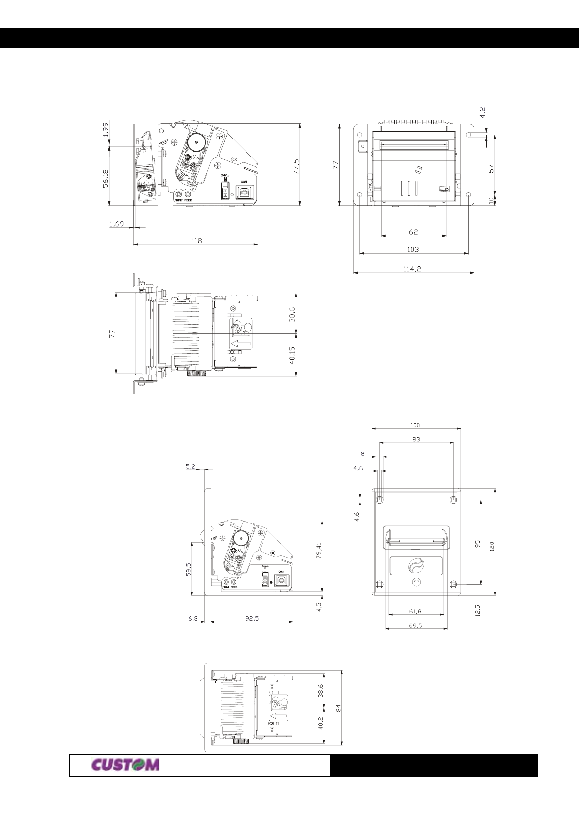
3. TECHNICAL SPECIFICATIONS
3.2 DIMENSIONS
3.2.1 TG2460-U-A
3.2.2 TG2460-U-N
(Fig.3.1)
(Fig.3.2)
33-
TG1260/2460
Page 85
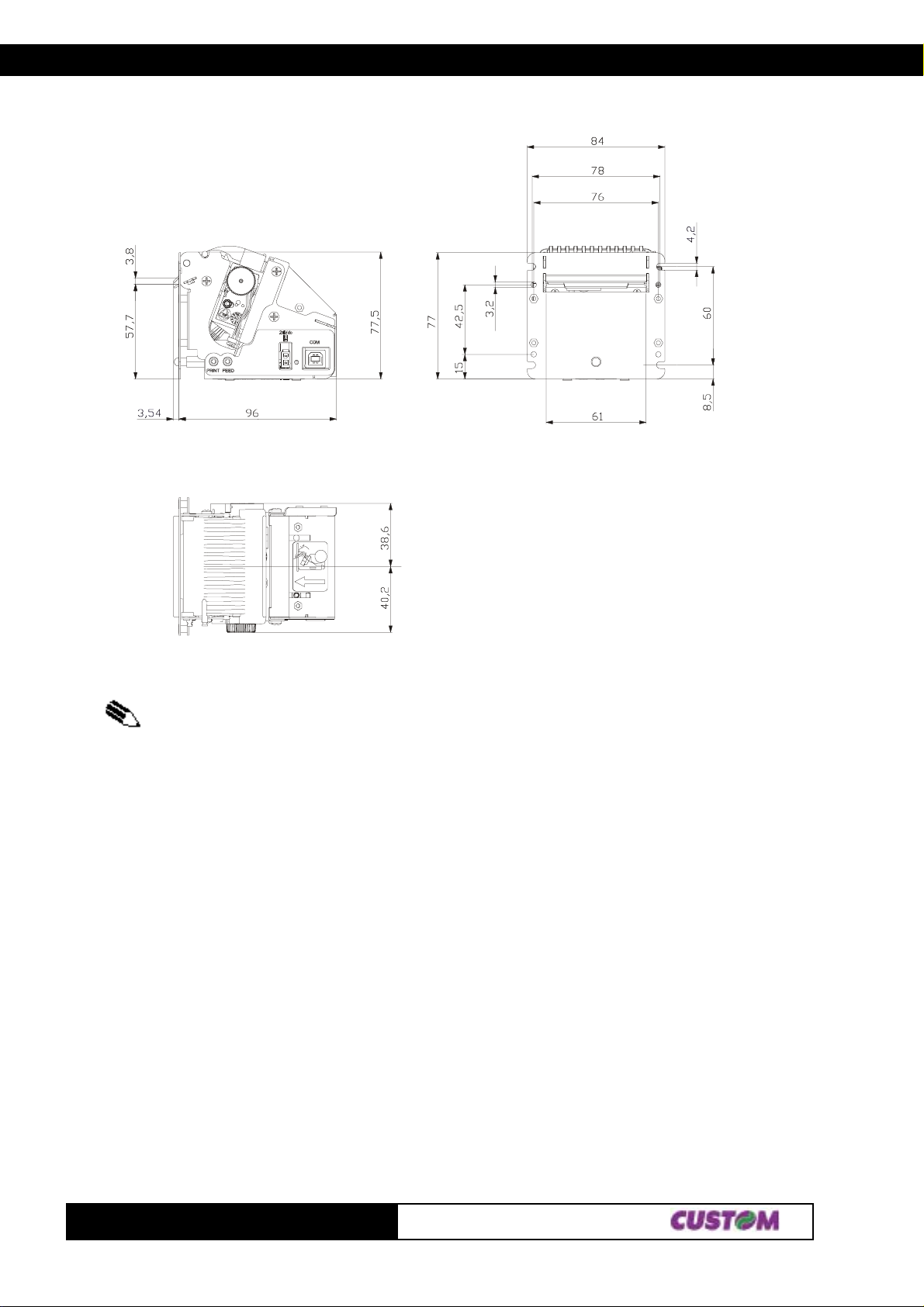
3.2.3 TG2460-U-M
3. TECHNICAL SPECIFICATIONS
(Fig.3.3)
NOTE: the figures in this part show the USB interface model but the dimensions are the same
even for the serial RS232 interface model.
TG1260/2460
43-
Page 86
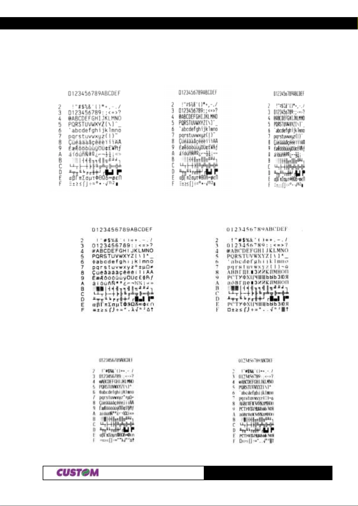
4. CHARACTER SET
4.1 CHARACTER SET
The printer has seven sets of 224 character each one. In the following figures are shown the examples:
ESC/POSTM 32 columns ESC/POSTM 42 columns ESC/POSTM 56 columns
DPT 24 FONT A DPT 24 FONT B
DPT 42 FONT A DPT 42 FONT B
14-
TG1260/2460
Page 87

4. CHARACTER SET
Blank page
TG1260/2460 24-
Page 88
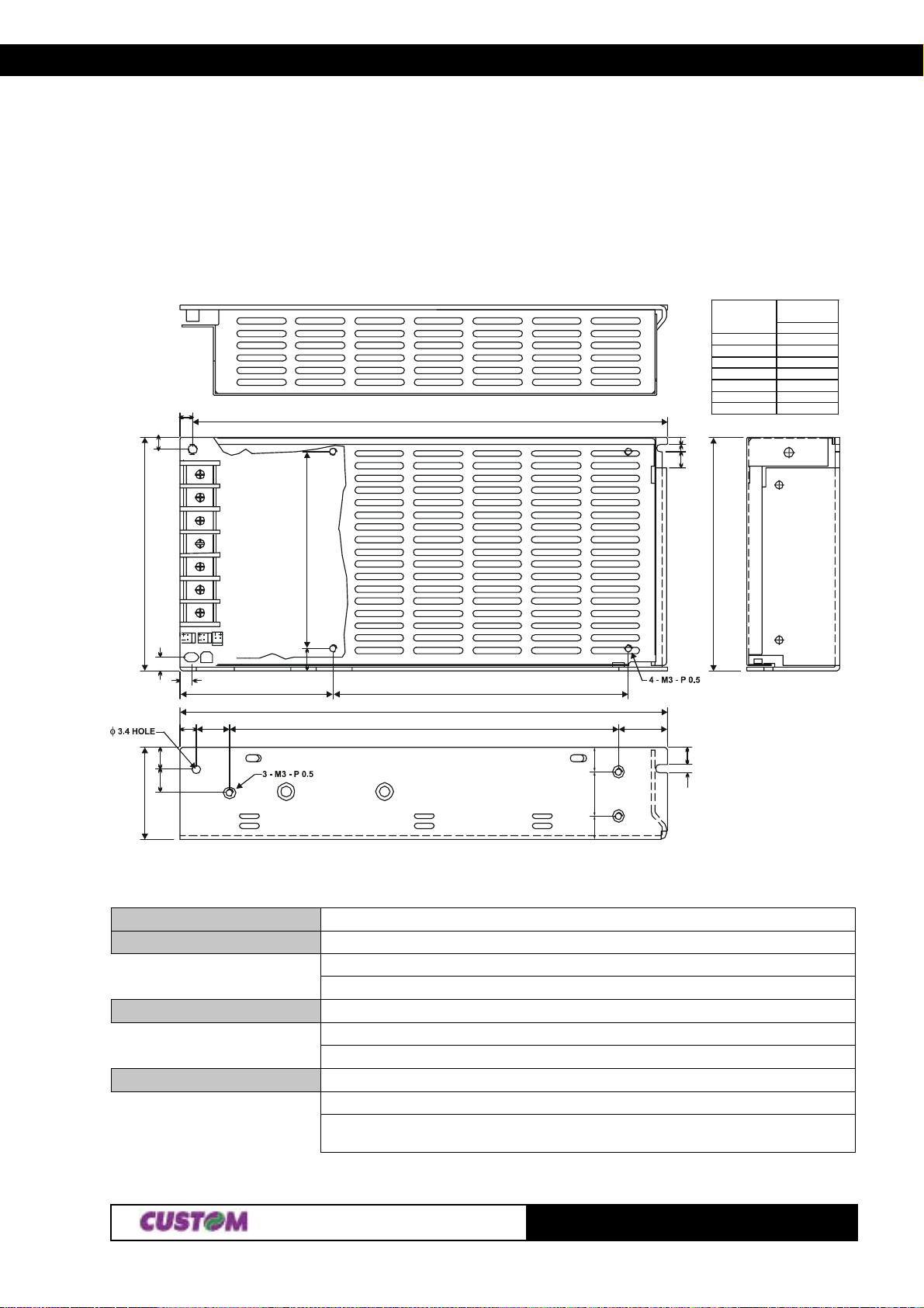
APPENDIX A - ACCESSORIES AND SPARE PARTS
A.1 ACCESSORIES
A.1.1 Power supply
A.1.1.1 Power supply for TG2460
The figure below illustrates the power supply provided by Custom to be used for printer operation.
(Fig.A.1)
RANGE
< 8
8 25
÷
25 80
÷
80 250
÷
250 800
÷
800 2600
÷
5
5
CN1
193.0
L
N
FG
-V
95.0
-V
+V
+V
ANGULAR
Note : Dimensioni in mm
3
3
6.5
95.0
TOLERANCE
B
±
0.1
±
0.15
±
0.25
±
0.4
±
0.8
±
1.5
±
0.3°
5.5
4.5
6.5
9.0
9.5
38
62.0
13.5
9.0
120.0
198.0
158.0
20.0
10.0
18.0
10
7.0
3.5
PPSPS-100-24V Switching power supply 24V÷100W
Imput specification
Input voltage 85V ÷ 264
Current 0A ÷ 4,5A
Input frequency 47 Hz ÷ 63 Hz
Output specifications
Output volatge 24V
Output current Min. Max. 0A ÷ 4,5A
Efficiency Min 80%
Enviromental conditions
Operating temperature 0°C ÷ 70°C
Humidity 20% ÷ 85% Rh (w/o condensation)
Storage temperature/ -10°C ÷ 75°C/
Humidity 10% ÷ 95% Rh (w/o condensation)
(T ab.A.1)
Protection devices: Shortcircuit, overload and overvoltage.
TG1262-24601A-
Page 89
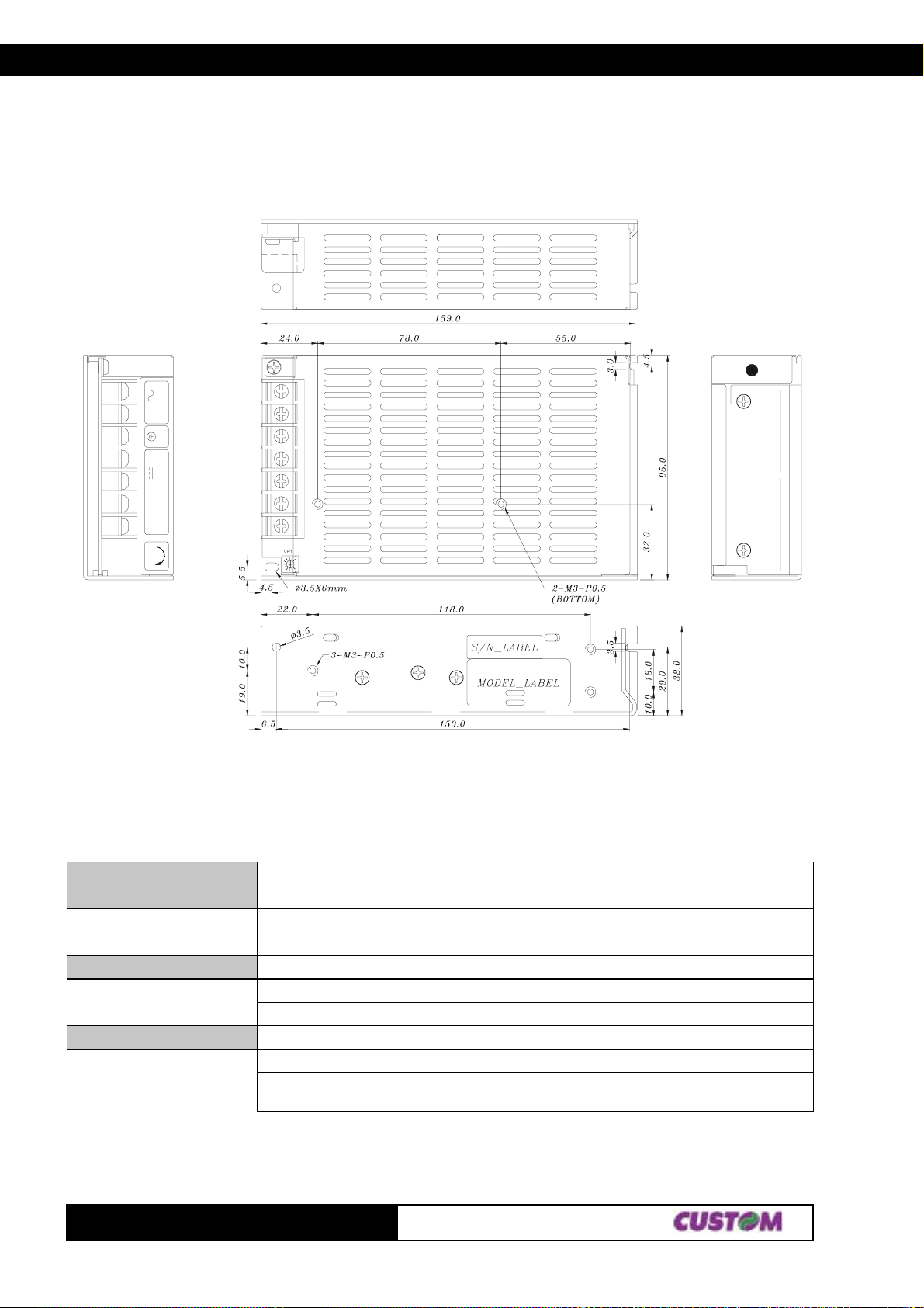
APPENDIX A - ACCESSORIES AND SPARE PARTS
A.1.1.2 Power supply for TG1260
The figure below illustrates the power supply provided by Custom to be used for printer operation.
(Fig.A.1.2)
IN
NL
OUTPUT
+V+V-V -V
V
ADJ
L
N
PE
-V
-V
+V
+V
(T ab.A.1.2)
PPSPS-070-12V Switching power supply 12V÷070W
Input specification
Input voltage 85V ÷ 264
Current 0A ÷ 1,8A
Inpout frequency 47 Hz ÷ 63 Hz
Specifiche di uscita
Output voltage 12V
Output current Min. Max. 0A ÷ 6,0A
Efficency Min 80%
Condizioni ambientali
Operating temperature 0°C ÷ 70°C
Humidity 20% ÷ 85% Rh (w/o condensation)
Storage temperature/ -10°C ÷ 75°C/
Humidity 10% ÷ 95% Rh (w/o condensation)
Protection devices: Shortcircuit, overload and overvoltage.
TG1260-2460
2A-
Page 90
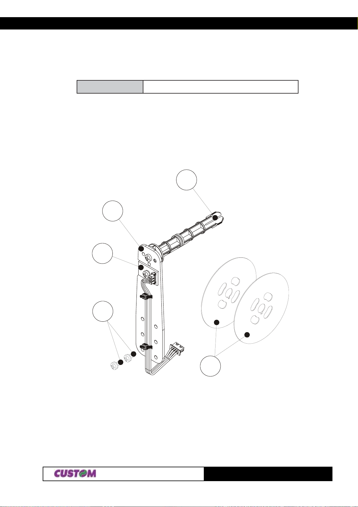
APPENDIX A - ACCESSORIES AND SPARE PARTS
A.1.2 Adjust able p aper holder support kit
For the printer is available a swinging paper holder support kit (see fig. A.2). This accessory allows to use
bigger diameter paper rolls (max 80mm).
0642GT-PSXCProsnesCFQdnatiKtroppusredlohrepaP
The kit is already assembled as shown in fig A.2.
Paper holder support kit:
1- Paper holder support
2- Paper roll pin
3- Near paper end sensor board
4- T wo fastening screws of the paper holder support to the printer frame (M3x6)
5- T wo disks for the paper roll cont ainment
(Fig.A.2)
2
3
4
1
5
TG1262-24603A-
Page 91
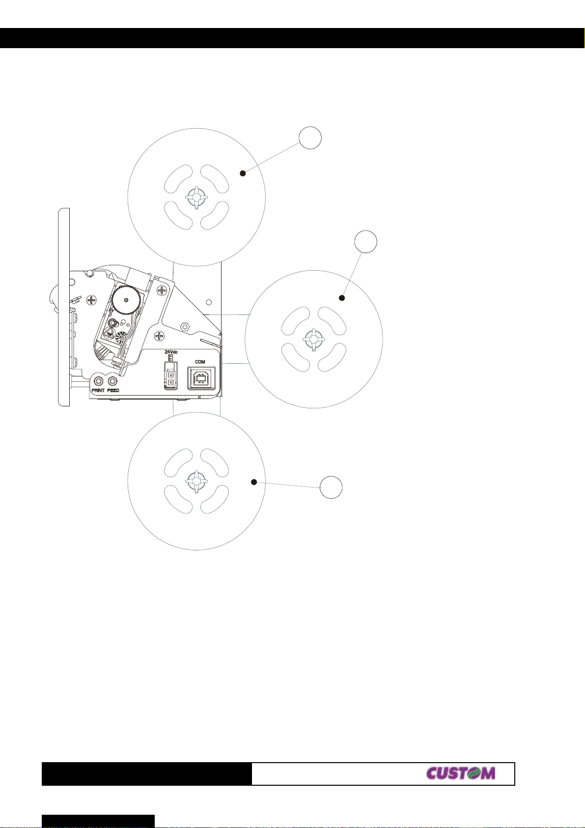
APPENDIX A - ACCESSORIES AND SPARE PARTS
Assembling instructions
The paper holder support positioning isn’t fixed but adjustable on 3 different positions: back, lower and upper
as shown in fig. A.3.
1
1 = Upper positioning
2 = Back positioning
3 = Lower positioning
2
(Fig.A.3)
3
TG1260-2460
4A-
Page 92
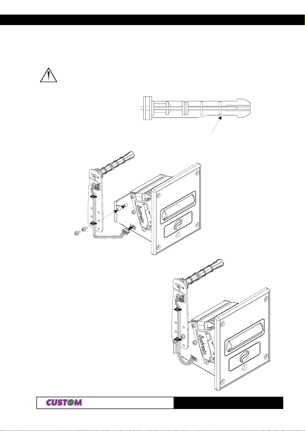
APPENDIX A - ACCESSORIES AND SPARE PARTS
Fastening the paper holder support in upper position
Fix the paper holder support to the printer frame by the two fastening screws on issue in the kit. Screw them
where shown in fig. A.4 and connect the near p aper end sensor cable to the printer connector .
WARNING: Check the paper roll pin is assembled with the beveled side turned in the low position
(see the paper roll containment disks part). If this condition isn’t verified, unloose the fastening
screw of the pin to the paper holder support and locate it in the right position.
BEVELED SIDE
(Fig.A.5)
(Fig.A.4)
TG1262-24605A-
Page 93
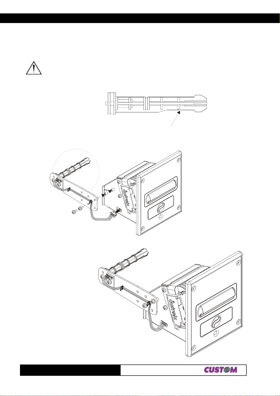
APPENDIX A - ACCESSORIES AND SPARE PARTS
Fastening the paper holder support in back position
Fix the paper holder support to the printer frame by the two fastening screws on issue in the kit. Screw them
where shown in fig. A.6 and connect the near p aper end sensor cable to the printer connector.
WARNING: Check the paper roll pin is assembled with the beveled side turned in the low position
(see the paper roll containment disks part). If this condition isn’t verified, unloose the fastening
screw of the pin to the paper holder support and locate it in the right position.
BEVELED SIDE
(Fig.A.7)
(Fig.A.6)
TG1260-2460
6A-
Page 94
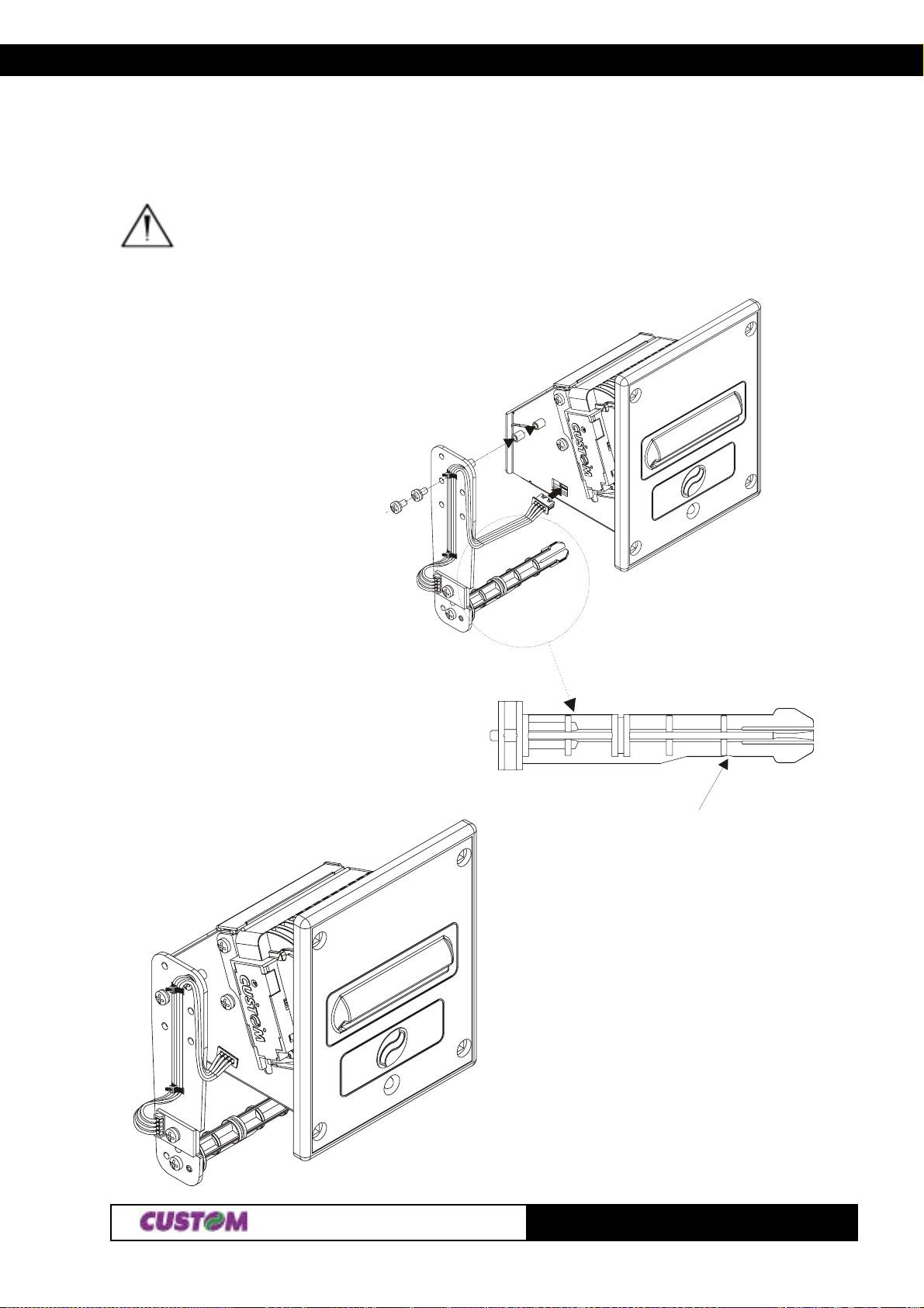
APPENDIX A - ACCESSORIES AND SPARE PARTS
Fastening the paper holder support in lower position
Fix the paper holder support to the printer frame by the two fastening screws on issue in the kit. Screw them
where shown in fig. A.8 and connect the near p aper end sensor cable to the printer connector.
WARNING: Check the paper roll pin is assembled with the beveled side turned in the low position
(see the paper roll containment disks part). If this condition isn’t verified, unloose the fastening
screw of the pin to the paper holder support and locate it in the right position.
(Fig.A.8)
BEVELED SIDE
(Fig.A.9)
TG1262-24607A-
Page 95
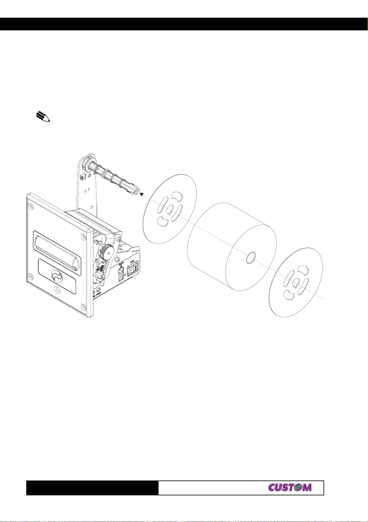
APPENDIX A - ACCESSORIES AND SPARE PARTS
Using the paper roll containment disks
The paper holder support kit is equipped with two paper roll containment disks. The disks operates to keep the roll
paper in the right position. They are realized with holes, which let the near paper end sensor on the paper holder
support works correctly , and with a slot, which hinder the disks from rotating around their own axises . In this slot
must be inserted the special paper roll pin feather, which has to be assembled turned toward the lower position to
avoid paper jam. In the following figure A.10 is shown how to assemble the paper roll containment disks on the
paper roll pin.
NOTE: These remarks are valid for all the printer models available.
TG1260-2460
(Fig.A.10)
8A-
Page 96
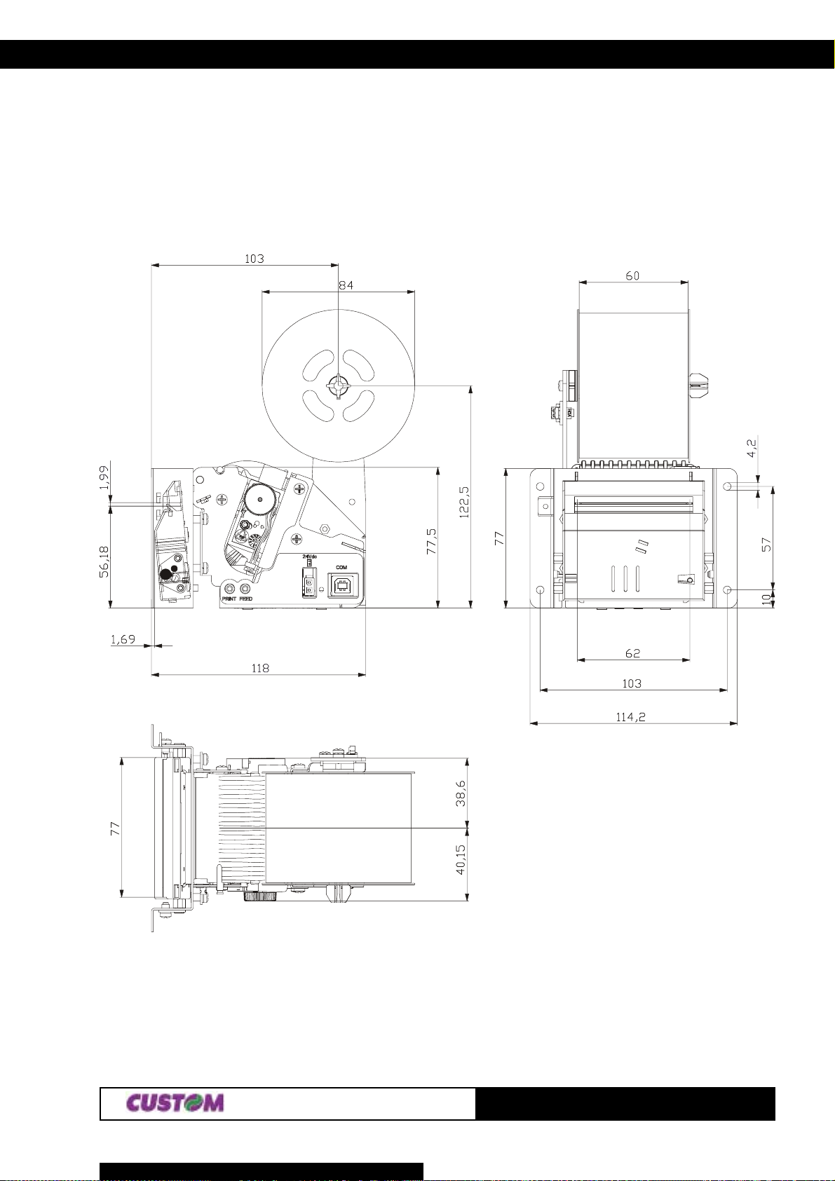
APPENDIX A - ACCESSORIES AND SPARE PARTS
Dimensions of printer with paper holder support
TG2460-U-A model (USB interface, metal front panel and autocutter model)
(Fig.A.1 1)
TG1262-24609A-
Page 97
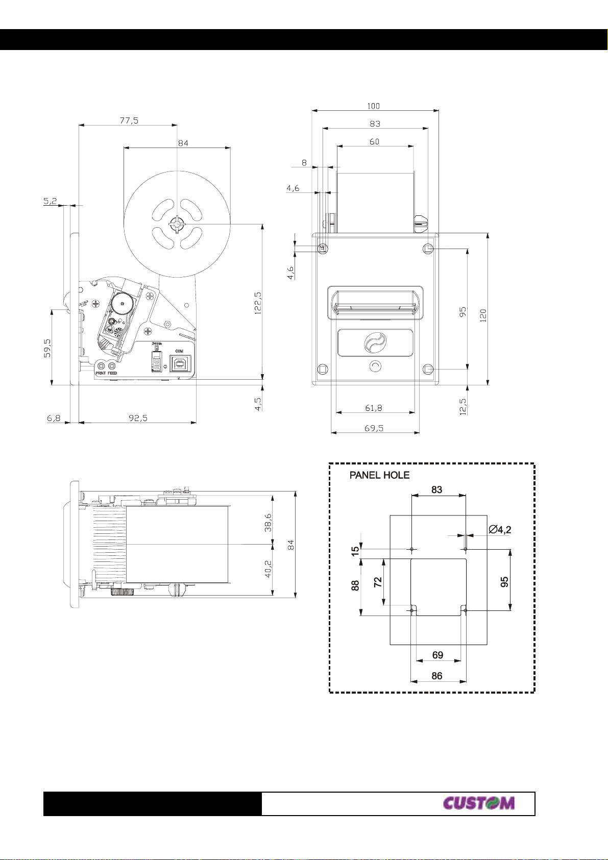
APPENDIX A - ACCESSORIES AND SPARE PARTS
TG2460-U-N model (USB interface and plastic front panel)
(Fig.A.12)
TG1260-2460
10A-
Page 98
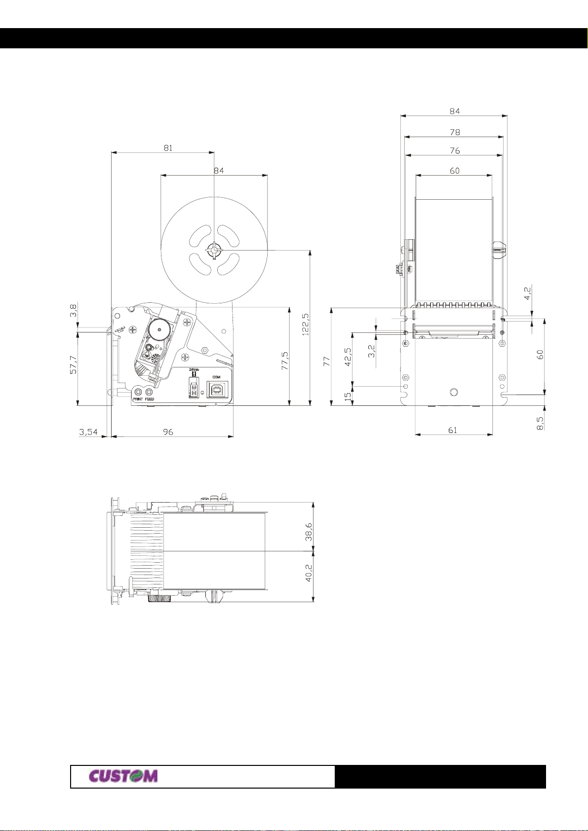
APPENDIX A - ACCESSORIES AND SPARE PARTS
TG2460-U-M model (USB interface and metal front panel without autocutter)
TG1262-246011A-
(Fig.A.13)
Page 99
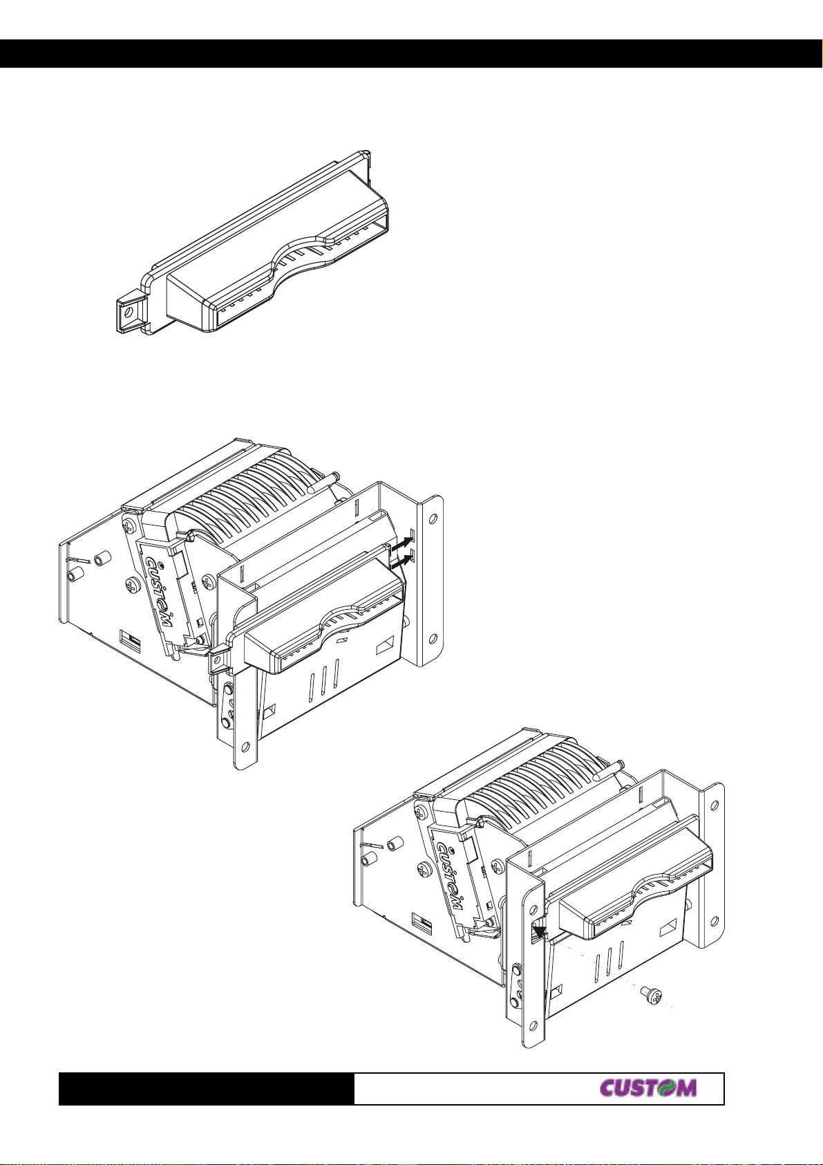
APPENDIX A - ACCESSORIES AND SPARE PARTS
A.1.3 Paper dispenser unit
Assembling paper dispenser unit:
(Fig.A.14)
(Fig.A.15)
Assemble the fastening screw of paper
dispenser unit to the plate which holds the
autocutter.
Insert the paper dispenser unit feathers
in their seats on the plate which holds
the autocutter.
TG1260-2460
(Fig.A.16)
12A-
Page 100
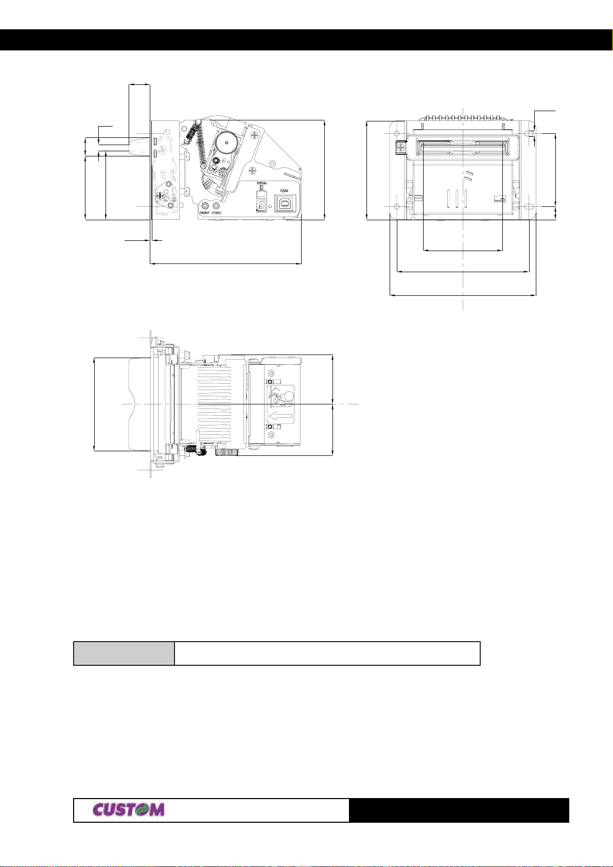
APPENDIX A - ACCESSORIES AND SPARE PARTS
8.2
7.2
24.8
2.5
Ø2.1
38.7
26.8
0.8
59
38.5
28.5
5
31
51.5
57.1
36.4
A.2 SP ARE PARTS
Paper rolls
20.1 19.3
55X06TCR
llorrepaplamrehtmm06
(T ab.A.4)
TG1262-246013A-
 Loading...