


 Loading...
Single Wet
Vacuum Pump
CV-101 FS (1HP) & CV-102 FS (2HP)
Installation, Operation & Care Manual

Table of Contents
Section I Introduction |
|
|
Specifications........................................................................................................................... |
2 |
|
Classification............................................................................................................................ |
2 |
|
Section II Pre-installation |
|
|
Site Requirements.................................................................................................................. |
3 |
|
Suggested Pump Sites............................................................................................................ |
4 |
|
Typical Utility Locations & Measurements....................................................................... |
4 |
|
Section III |
Installation |
|
Installation Kit......................................................................................................................... |
5 |
|
Cabinet Installation................................................................................................................ |
6 |
|
Drip Plate Kit Installation..................................................................................................... |
7 |
|
Water Supply Line................................................................................................................. |
8 |
|
Vacuum Line............................................................................................................................ |
9 |
|
Waste Line............................................................................................................................. |
10 |
|
Water Recirculator (Optional)................................................................................... |
11-12 |
|
Electrical Connection.......................................................................................................... |
13 |
|
Section IV |
Operation & Care |
|
General Operation.............................................................................................................. |
14 |
|
Maintenance Schedule................................................................................................... |
14-15 |
|
Recycler Cleaner.................................................................................................................. |
16 |
|
SectionV User Service Information |
|
|
Service Instruction............................................................................................................... |
17 |
|
Trouble Shooting Charts.............................................................................................. |
17-19 |
|
Relay Box |
............................................................................................................................... |
19 |
Fuse Replacement................................................................................................................ |
20 |
|
Wiring Schematic................................................................................................................. |
21 |
|
Air/Water Flow Circulation Diagram.............................................................................. |
22 |
|
Vacuum Pump System Repair Procedure................................................................. |
23-25 |
|
SectionVI |
Parts List/Diagrams |
|
1 HP Single PumpAssembly............................................................................................... |
26 |
|
2 HP Single PumpAssembly............................................................................................... |
27 |
|
Electrical Box........................................................................................................................ |
28 |
|
SectionVII |
Repair Parts |
|
Water ControlAssembly................................................................................................... |
29 |
|
Anti-SiphonValveAssembly............................................................................................... |
30 |
|
Water SolenoidValveAssembly........................................................................................ |
30 |
|
Intake ManifoldAssembly................................................................................................... |
31 |
|
Primary / Secondary Filter................................................................................................. |
31 |
|
Limited Warranty ................................................................................................................. |
32 |
|
EMC Information.............................................................................................................. |
33-34 |
|
Single Wet Vacuum Pump 1
Section I Introduction |
Single Wet Vacuum Pump |
This manual contains installation, operation, care and repair instructions and user service information for the CustomAir® Single Wet Vacuum Pump (CV-101 FS/CV-102 FS).
The Single Wet Vacuum Pump is designed to provide trouble-free service when installed, operated and cared for according to the procedures set forth in this manual.
 WARNING
Do not modify this equipment. Modification will void the warranty and could result in serious injury.
Specifications
Motor |
CV-101 FS |
CV-102 FS |
|
|
|
Power Rating: |
1 HP |
2 HP |
Voltage: |
115/208/230 |
|
208/230 |
|
|
Amps (each motor): |
15/7.5/7.5 |
15/15 |
Cycle: |
60 Hz. |
|
Phase: |
Single |
|
Running Speed: |
3450 RPM |
|
Ambient Temperature Range: 10-40°C/50-104°F |
||
Wire Size: |
12 GA. |
|
Vacuum
Mercury Pull (Sealed Sys.): Approx. 20-25" Hg.
Adjust.
Usable CFM: |
15 |
30 |
Use factor (Number of |
|
|
high-volume hoses |
|
|
open simultaneously): |
1.5 |
3 |
Gauge Accuracy: |
ASME/ANSI B40.1 Grade B |
|
(+/- 3/2/3%) |
|
|
Water Requirements
Gallons Per Minute: |
1/2 |
1 |
Dimensions
Height: |
16" |
20" |
Width: |
12" |
14" |
Depth: |
9” |
11” |
Shipping Weight: 68 lbs. |
78 lbs. |
Approvals:
Certified to ANSI/AAMI
ES60601-1:2005(R2012) and certified to CAN/CSA Stan- dard C22.2 No. 60601-1:08, and comply with NFPA 99C level 3 vacuum requirements. They are manufactured in a
FDA Registered ISO 13485:2003 certified facility.
Classification
–Type of protection against electric shock: Class 1 Equipment
–Degree of protection against the ingress of water: Ordinary
–Equipment not suitable for use in the presence of a flammable anesthetic mixture with air or with oxygen or nitrous oxide.
–Mode of operation: Continuous
–Recommended Temperature ranges:
•Operating Temperature range within 1040º C/ 50-104º F
•Operating Relative Humidity Range: 0-95%. No condensing moisture.
•Operating Atmospheric pressure range: 63-105 kPa
•Transport/storage temperature range within -40ºC to 70ºC/-40º to 158ºF
•Relative humidity range for transportation and storage within 10% to 100%
•Atmospheric pressure range for transportation and storage within 50 - 105 kPa
Explanation of Symbols used on Equipment:
= Attention,ConsultAccompanying Documents
= Protective EarthTerminal
= Caution.Electrical Shock Hazard.Refer Servicing
to Qualified Personnel
= Hot Surface
 = European Certification
The authorized European representative is: DentalEZ (GB) Ltd.,ClevelandWay
Hemel Hempstead,Hertfordshire,HP2 7DY,UK
2 Installation, Operation and Care Manual
Section II Pre-Installation
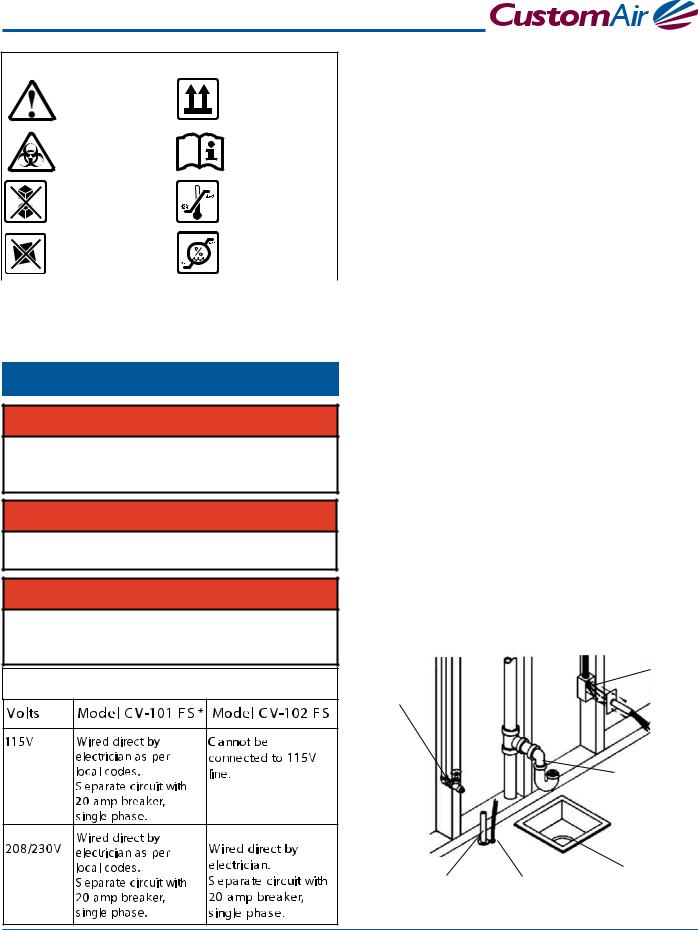
The Wet Vacuum Pump labels include safety symbols with special meanings
|
|
|
This means there is more |
|
|
|
|
This notifies handlers that the box must |
|
|
|
information available in this User |
|
|
|
|
|
|
|
|
|
|
|
|
remain upright at all times. |
|
|
|
|
Guide. |
|
|
|
|
|
|
|
|
|
|
|
|
|
|
|
|
|
|
|
|
|
|
|
|
|
|
This notifies users to be aware |
|
|
|
|
Used to advise the operator to consult |
|
|
|
of biohazardous materials that may |
|
|
|
|
|
|
|
|
be present. |
|
|
|
|
the accompanying documents. |
|
|
|
|
|
|
|
|
|
|
|
|
|
|
|
|
|
|
|
|
|
This notifies handlers that this box |
|
|
|
|
This notifies handlers of the safe |
|
|
|
|
|
|
|
temperature range for the contents |
|
|
|
|
should never be stacked. |
|
|
|
|
|
|
|
|
|
|
|
|
in box. |
|
|
|
|
|
|
|
|
|
|
|
|
|
|
|
|
|
|
|
|
|
|
This warns handlers not to allow the |
|
|
|
|
This notifies handlers of the safe |
|
|
|
box to be placed on an unlevel surface |
|
|
|
|
humidity range of the contents in |
|
|
|
due to risk of tipping. |
|
|
|
|
the box. |
|
|
|
|
|
|
|
|
|
The following Pre-installation information will assist in making a quick, easy and quality installation. However, if there are any questions, contact a CustomAir technical service representative at 1-866-DTE-INFO.
Site Requirements
 WARNING
Not for use in an oxygen rich environment. Large concentrations may cause a fire in the vacuum unit and may cause an exhaust hazard.
 WARNING
To avoid risk of electric shock, this equipment must only be connected to a supply mains with protective earth.
 WARNING
Electrician must provide a means to isolate the circuit electrically from the supply mains on all poles simultaneously.
Electrical Requirements
Before the Single Wet Vacuum Pump can be properly installed, the following utilities must be supplied:
Electrical
All electrical supply lines and control wiring should be supplied and installed by a licensed electrician according to local building codes.
*Model CV-101 FS is manufactured and shipped for 115V operation. This model may be converted to 230V
operation by qualified installation technicians only following connection diagrams inside the pump control box.
Water
Water line must be installed by a plumber according to local building codes. Requirements: 1/2" gate valve reduced to 1/8" FIP.
Waste
Waste line must be installed by a plumber according to local building and health codes. Requirements: reduce connection to 1" FIP or floor sink. When using floor sink, order a floor sink adapter.
Vacuum Lines
Vacuum lines must be installed by a plumber according to local building and electrical codes. Requirements: 1" IPS, PVC, Schedule 40.
LowVoltage Control Line (Optional)
If remote low voltage is desired, a licensed electrician should install 18-2 thermostat wire from the pump location to the operatory switches. (Use 18-3 thermostat wire for lighted switch.)
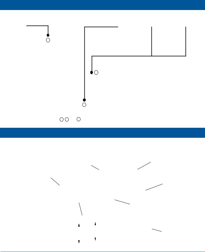
Water Line |
Electrical |
115V or 230V |
|
1/2" Gate |
Connection Box |
Valve |
|
Reduced to |
|
1/8" FIP |
|
Waste Line
"P"Trap Reduced to 2" FIP
Vacuum Line |
|
Floor Sink |
|
LowVoltage Line |
Use Floor Sink |
||
1" IPS,PVC, |
|||
Schedule 40 |
24V (Optional) |
Adapter |
|
|
Single Wet Vacuum Pump 3
Section II Pre-Installation |
Single Wet Vacuum Pump |
Suggested Pump Sites
SURGERY |
OPERATORY |
OPERATORY |
OPERATORY |
OPERATORY |
|
SCRUB |
|
|
|
1
|
|
|
3 |
|
|
|
EQUIPMENT |
|
|
STORAGE |
ROOM |
|
|
|
|
WOMEN |
MEN |
|
WAITING ROOM |
OFFICE
ROOMDARK 2
NOTE: 1 2 and 3 are alternate pump locations.
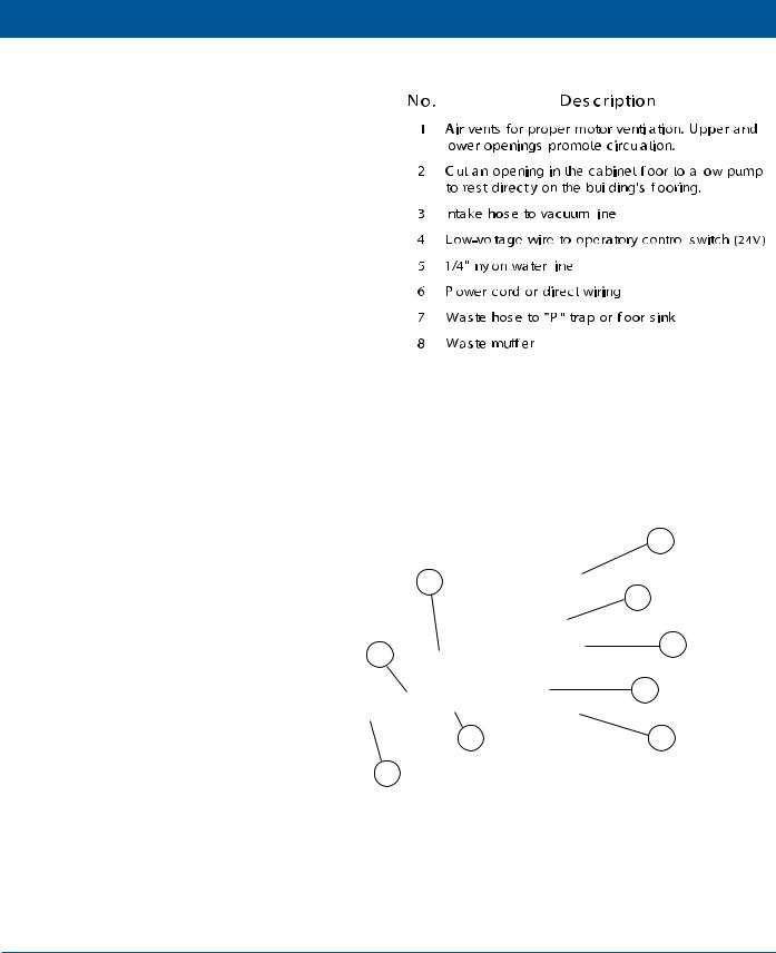
Typical Utility Locations and Measurements
|
Drain |
|
|
Electric Outlet |
|
|
|
|
|
Water Line |
|
|
|
|
|
|
|
|
LowVoltage 18-3 |
|
|
|
|
for Lighted Switch |
Vacuum Line |
|
P Trap |
NOTE: A and B |
|
|
|
|
||
|
|
|
A |
are alternate waste |
|
|
|
|
|
|
|
|
|
line connection |
|
|
|
|
methods. |
|
|
|
|
|
|
|
|
|
|
|
|
8" |
Floor Sink |
|
|
|
|
|
B |
12" |
|
|
||
|
|
|
|
|
Locations & measurements are approximate.
4 Installation, Operation and Care Manual

Section III Installation
Installation Kit
Each vacuum pump is supplied with an installation kit (PN: 64568036).
1 |
2 |
3 |
4 |
|
|||
|
|
|
6 |
8 |
|
5 |
7 |
||
|
|||
|
|
|
11 |
12 |
9 |
|
|
10 |
|
14
13
15
16 17
Single Wet Vacuum Pump 5
Section III Installation |
Single Wet Vacuum Pump |
Cabinet Installation
If a mechanical area is not available, the vacuum |
|
|
Cabinet Illustration |
|||||||||||||
pump can be installed in a darkroom or laboratory, |
|
|
|
|
|
|
|
|
|
|
|
|
|
|
|
|
|
|
|
|
|
|
|
|
|
|
|
|
|
|
|
|
|
usually in the sink cabinet. In this type of installation, |
|
|
|
|
|
|
|
|
|
|
|
|
|
|
|
|
it is important to make sure the pump motor is prop- |
|
|
|
|
|
|
|
|
|
|
|
|
|
|
|
|
|
|
|
|
|
|
|
|
|
|
|
|
|
|
|||
erly ventilated. In most cases, venting in the door and |
|
|
|
|
|
|
|
|
|
|
|
|
|
|
|
|
|
|
|
|
|
|
|
|
|
|
|
|
|
|
|||
|
|
|
|
|
|
|
|
|
|
|
|
|
|
|||
toe board of the cabinet will supply enough cooling |
|
|
|
|
|
|
|
|
|
|
|
|
|
|
|
|
|
|
|
|
|
|
|
|
|
|
|
|
|
|
|||
air to the motor. It is also necessary to cut a hole in |
|
|
|
|
|
|
|
|
|
|
|
|
|
|
|
|
|
|
|
|
|
|
|
|
|
|
|
|
|
|
|||
|
|
|
|
|
|
|
|
|
|
|
|
|
|
|||
the cabinet's flooring to allow the rubber pump pads |
|
|
|
|
|
|
|
|
|
|
|
|
|
|
|
|
|
|
|
|
|
|
|
|
|
|
|
|
|
|
|||
to stand directly on the building's flooring. Do not |
|
|
|
|
|
|
|
|
|
|
|
|
|
|
|
|
|
|
|
|
|
|
|
|
|
|
|
|
|
|
|
|
|
|
|
|
|
|
|
|
|
|
|
|
|
|
|
|||
bolt the pump to the floor. Quiet and vibration-free |
|
|
|
|
|
|
|
|
|
|
|
|
|
|
|
|
|
|
|
|
|
|
|
|
|
|
|
|
|
|
|
|
|
operation is assured when the pump is installed |
|
|
|
|
|
|
|
|
|
|
|
|
|
|
|
|
|
|
|
|
|
|
|
|
|
|
|
|
|
|
|||
|
|
|
|
|
|
|
|
|
|
|
|
|
|
|
|
|
free-standing on the supplied rubber insulators. |
|
|
|
|
|
|
|
|
|
|
|
|
|
|
|
|
|
|
|
|
|
|
|
|
|
|
|
|
|
|
|
|
|
|
|
|
|
|
|
|
|
|
|
|
|
|
|
|
|
|
|
|
|
|
|
|
|
|
|
|
|
|
|
|
|
|
|
|
|
|
|
|
|
|
|
|
|
|
|
|
|
|
|
|
|
|
|
|
|
|
|
|
|
|
|
|
|
|
|
|
|
|
|
|
|
|
|
|
|
|
|
|
|
|
|
|
|
|
|
1 |
5 |
4 |
|
|
6 |
3 |
|
|
|
2 |
7 |
1 |
8 |
|
6 Installation, Operation and Care Manual
Section III Installation
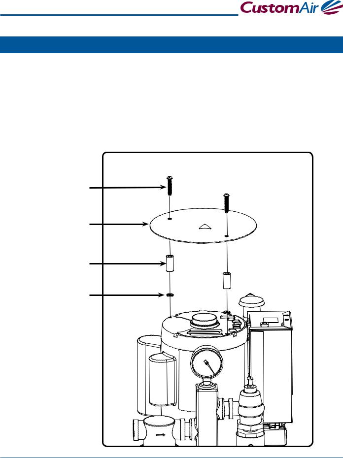
Drip Plate Installation
Instructions
1.Locate two holes on top of the pump motor.
2.Place parts in order as shown below, insert screws and tighten.
Screw
Drip Plate Cover
Bushing
Self-retaining Washer
Single Wet Vacuum Pump 7
Section III Installation |
Single Wet Vacuum Pump |
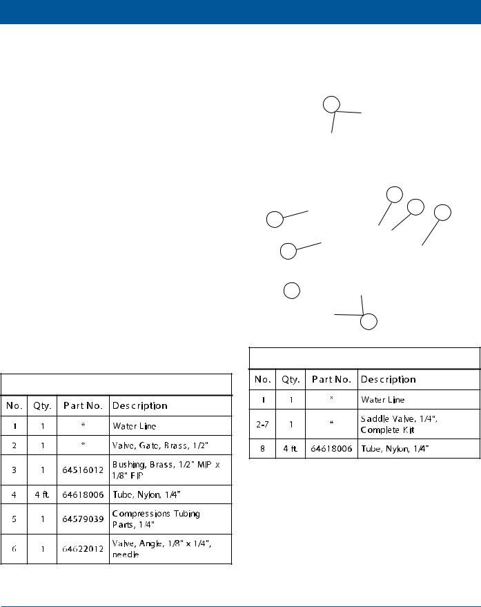
Water Supply Line
The water going to the unit acts as a pump sealant and cooling agent. When the vacuum pump is in operation, the water supply must be on at all times. There are two methods of installation:
1/8" MIP AngleValve Installation
The plumber supplies the water line and installs a 1/2" brass gate valve on the water supply line. Connect the 1/4" nylon tubing and slide the nut and brass ferrule over the tubing. Push the tubing in the valve as far as possible. Make sure the tapered end of the ferrule is facing the end of the tubing and tighten the nut.
SaddleValve Installation
A saddle valve may be tapped into an existing cold water line. Follow the instructions on the saddle valve package.
2
|
6 |
|
1 |
7 |
8 |
|
||
|
|
|
|
3 |
|
4 
5
AngleValve Installation
SaddleValve Installation
* Plumber Supplies
* Plumber Supplies
8 Installation, Operation and Care Manual
Section III Installation
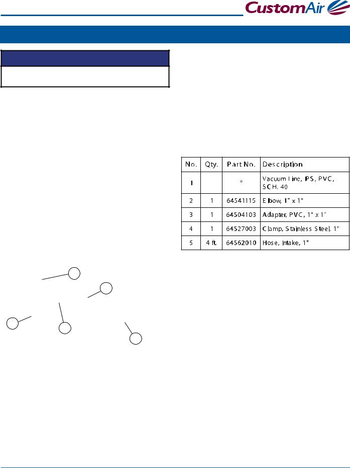
Vacuum Line
NOTICE
All vacuum systems must be installed according to local building and electrical codes.
Vacuum lines must be installed by a local plumber according to local building codes. All vacuum lines and risers are recommended to be IPS, PVC, SCH. 40.
Type “M” copper should be used if local code does not allow the use of PVC.
Care should be taken to slope the lines 1" for every 20' of run toward the vacuum pump(s). This allows waste and liquids to flow with gravity, contributing to the efficiency of the vacuum system.
Make all connections using long radius sweep fittings. To promote unrestricted flow of air and waste liquids through the vacuum lines, directional flow connec- tions should be used.
Using 45º elbows for turns or avoiding obstructions is best; however, do not make a trap in the line, doing so will decrease the efficiency of the system.
2
4
1 |
3 |
|
5
All elbows and tees should be sized for the main line and sized down with bushing reducers to accommodate smaller lines.
Avoid sagging lines, which cause the formation of traps in the system and prevent good air and waste liquid flow.
Connect the evacuation system to the vacuum line us- ing the hose and fittings supplied in the installation kit.
* Supplied by Plumber
Single Wet Vacuum Pump 9
Section III Installation |
Single Wet Vacuum Pump |
Waste Line
The waste line carries water from the pumps and liquid waste from the operatory to the building's sewer system.
The waste line should follow the most direct path to the sewer connection with a minimum of bends and elevations, and must be installed according to local building and plumbing codes.
The exhaust connection should be made by either of two methods, floor sink connection or direct connection to “P” trap, depending on local code and building facilities.
Floor Sink Connection
Use floor sink adapter SA-100. Install as illustrated.
NOTICE
IMPORTANT: No part of the waste line should be more than three (3) feet above the level of the waste connection on the vacuum pump.
Direct Connection to "P"Trap
Use “P” trap-air gap, if required by local code. Install as illustrated.
1
2
3
1 |
3 |
|
6 |
|
4 |
||
|
|
|
|
|
4 |
|
7 |
|
2 |
5 |
|
8 
 1
1


 MIP
MIP 
 1-1/2” shank
*Floor SinkAdapter Parts
*Supplied by Plumber
* Supplied by Plumber
10 Installation, Operation and Care Manual
Loading...