

CustomAir 900-Series User and maintenance manual

Super Quiet LubeFree
Compressors
900 Series
Installation, Operation and Care Manual

Low voltage box
The low voltage relay box also called the control box is already installed on this compressor. The purpose
of the control box is for the end use to install all remotely Master Control Panel (24 Volt operated) that
can control the air from one location. By means of ONE switch the compressor can be turned off in the
dental ofce instead of going to the utility room. By having the control box/low voltage relay installed on
the compressor, you have all that is required for any future additions.

900 Series Compressors
1
Table of Contents
Section I Introduction
Specifications ............................................................................................................... 3
Model CA-913D / CA-923D / CA-925 ................................................................. 4
Model CA-925D / CA-927D / CA-929D ............................................................. 5
Section II Pre-installation
Unpacking .................................................................................................................... 6
Placement ..................................................................................................................... 6
Section III Installation
Unit Connections ....................................................................................................... 7
Grounding Instructions ............................................................................................ 8
Extension Cords ........................................................................................................ 9
Section IV Operation
General Operation .............................................................................................10-11
Cabinet Doors ...........................................................................................................11
Pressure Switch .........................................................................................................11
Section V Care
Maintenance Schedule ............................................................................................. 12
Cleaning Compressor ............................................................................................. 12
Inspecting Dryer ...................................................................................................... 13
Checking for Leaks .................................................................................................. 13
Testing Safety Valves ............................................................................................... 14
Replacing Intake Filter ............................................................................................. 14
Replacing Dryer Filters ........................................................................................... 15
Cleaning Non-return Valve .................................................................................... 15
Section VI User Service Information
Service Instruction ................................................................................................... 16
Troubleshooting Chart ........................................................................................... 17
Section VII Parts List / Diagrams
Model CA-913 / CA-923 Parts List .....................................................................18
Model CA-913 / CA-923 Diagram ....................................................................... 19
Model CA-925 Parts List .......................................................................................20
Model CA-925 Diagram ......................................................................................... 21
Model CA-925D Parts List .................................................................................... 22
Model CA-925D Diagram ...................................................................................... 23
Model CA-927D Parts List .................................................................................... 24
Model CA-927D Diagram ...................................................................................... 25
Model CA-929D Parts List .................................................................................... 26
Model CA-929D Diagram ...................................................................................... 27
Product Support Services ...........................................................................28


900 Series Compressors
3
Section I Introduction
This manual contains installation, operation and care instructions and user service information for the
CustomAir® 900 Series Compressors.
The lube-free 900 Series Compressors are designed to provide trouble-free service when installed, operated
and cared for according to the procedures set forth in this manual.
NOTE: Pump Time plus/minus 10%. Average at 20°C/68°F motor start temperature
Specifications
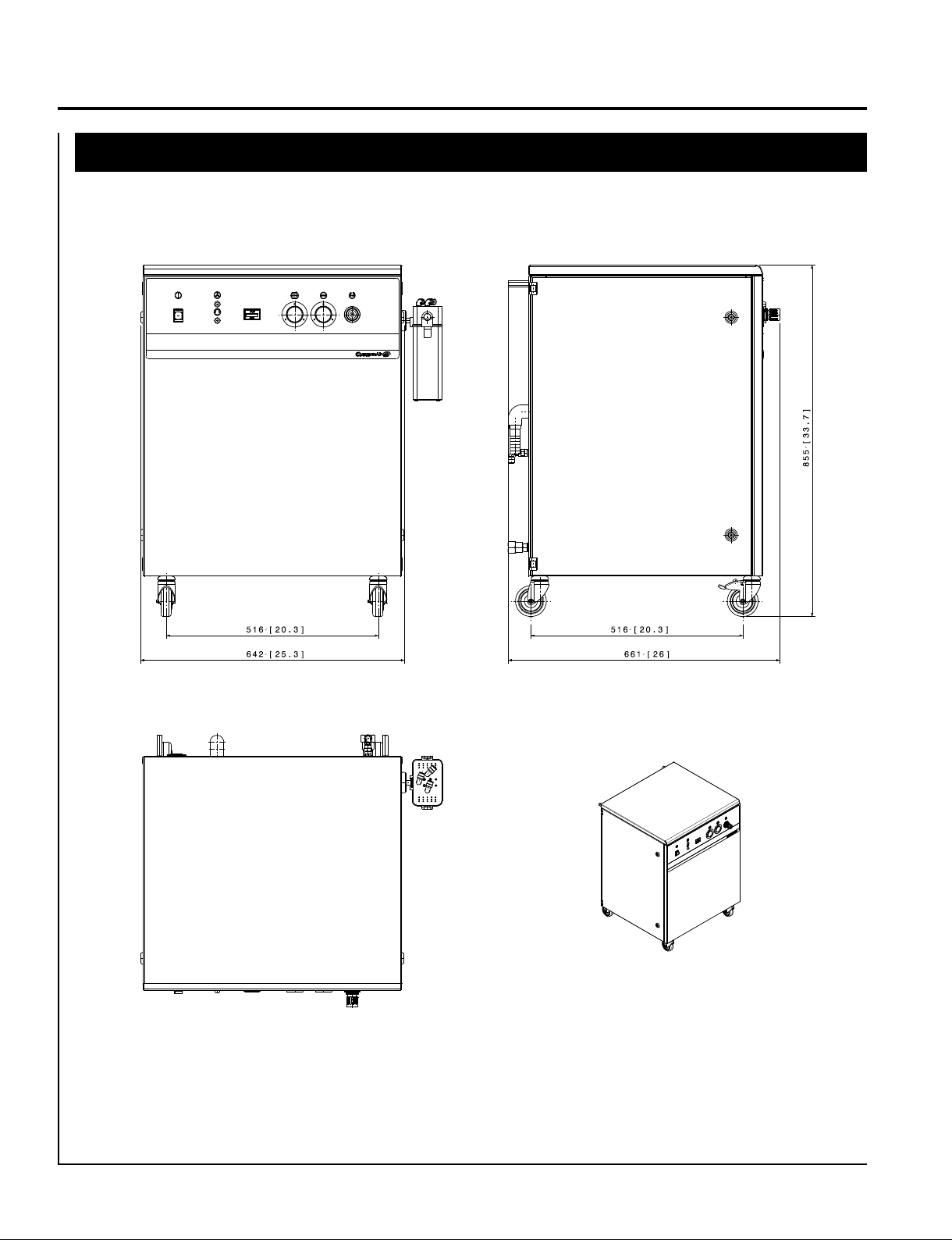
NOTE: The dimensions for each model are illustrated on Pages 3 through 5.
NOTE: The pressure dew point for all 900 series units is -40º C/-40°F.
Model CA-913D CA-923D CA-925
Users (max.) 3 3 5
Voltage (V/Hz) 120/60 230/60 230/60
Power (amps.) 15.0 8.2 8.3
Weight: (kg.) 112 112 118
(lbs.) 247 247 260
Dimensions: (mm) 665x638x861 665x638x861 665x638x861
LxWxH (in.) 26.18x25.11x33.89 26.18x25.11x33.89 26.18x25.11x33.89
Noise level (db) 50 50 53
Pump Time (sec.) 220 220 160
0-120 psi
Model CA-925D CA-927D CA-929D
Users (max.) 5 7 9
Voltage (V/Hz) 230/60 230/60 230/60
Power (amps.) 10.8 13.4 16.2
Weight: (kg.) 134 154 160
(lbs.) 294 340 353
Dimensions: (mm) 693x810x861 693x810x861 693x810x861
LxWxH (in.) 27.28x31.88x33.89 27.28x31.88x33.89 27.28x31.88x33.89
Noise level (db) 53 55 55
Pump Time (sec.) 160 105 80
0-120 psi
900 Series Compressors
4 Installation, Operation and Care Manual
Section I Introduction
Model CA-913D / CA-923D / CA-925

900 Series Compressors
5
Section I Introduction
Model CA-925D / CA-927D / CA-929D
900 Series Compressors
6 Installation, Operation and Care Manual
— WARNING —
When spraying flammable liquid, there may be danger of fire
or explosion
, especially in closed rooms.
— CAUTION —
The compressor is for indoor use only --
NOT FOR OUTDOOR USE!
1. Carefully remove the compressor from its shipping carton.
2. Visually inspect the unit for shipping damage. Contact the freight
carrier and supplier immediately if the unit has shipping damage.
(See Product Support Services, Page 28.)
1. Place the compressor in a dust-free, dry, cool and frost-free room.
— WARNING —
Place the compressor out of children's reach and never leave
children unattended
when the compressor is in use.
Section Il Pre-installation
Unpacking
Placement
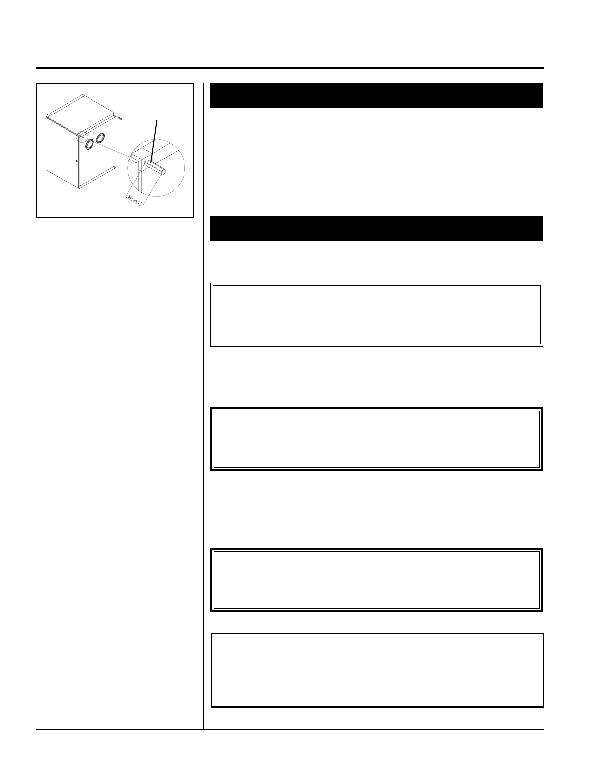
3. Install two spacer bolts on the back of the compressor cabinet to
maintain a minimum distance from the wall. This will help ensure
proper ventilation.
2. Do not install the compressor against a wall because doing so
would prevent the fans from functioning properly.
— NOTICE —
When using the compressor in connection with vital
equipment, an alternative air source should be available in
case of a defect in the compressor.
3
900 Series Compressors
7
Section Ill Installation
Unit Connections
— CAUTION —
Only connect the compressor to installations with the correct
voltage stated on the motor plate
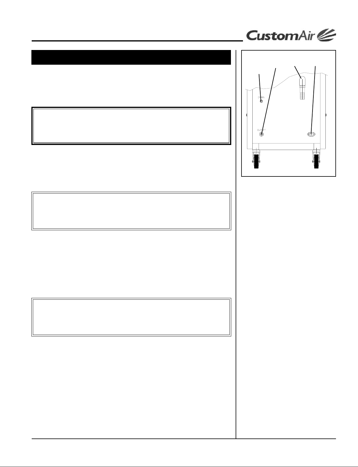
1. Mount the drain bottle visibly outside the metal cabinet.
2. Connect the tube from the drain bottle to the “drain” location in
the back of the cabinet.
— CAUTION —
Only connect equipment suitable for the maximum pressure
stated on the tank pressure gauge.
— WARNING —
Unless directions are followed and the original spare parts used,
physical injury or property damage may result.
The following information will assist in making a quick, easy and quality installation. However, if there are any questions, contact a CustomAir
technical service representative at 1-866-DTE-INFO (1-866-383-4636).
5. Connect the plug and cable and make sure the circuit is properly
protected. (See Grounding Instructions, Page 8.)
IMPORTANT NOTE: The air consumption of the equipment used with
the compressor must be sized properly to the compressor/number of users.
6. Connect the equipment to the “outlet” location in the back of
the cabinet.
7. Connect, the external air intake on the connecting piece on the
intake.
3. Make sure the operating voltage of the compressor corresponds
to the voltage of the socket.
(Refer to Specications, Page 3.)
4. Connect the supply cable to the back of the cabinet.
NOTE: Models CA-925D, CA-927D and CA-929D are mounted with
permanent cable.
2
6
7
4

900 Series Compressors
8 Installation, Operation and Care Manual
Section Ill Installation
Grounding Instructions
— WARNING —
Risk of electric shock could occur as a result of improper
grounding plug installation.
To reduce the risk of electric shock, this product must be grounded. In
the event of an electrical short circuit, grounding provides an escape wire
for the electric current.
This product is equipped with a cord having a grounding wire with an
appropriate grounding plug. The wire with insulation having a green or green
with yellow stripes outer surface is the grounding wire.
1. The plug must be plugged into a properly installed and grounded
outlet, which is in accordance with all local codes and ordinances.
2. If the plug provided does not fit the outlet, do not modify it in
any way. Have a qualified electrician install the proper outlet.
3. If repair or replacement of the cord or plug is necessary, do not
connect the grounding wire to either flat blade terminal.
4. Check with a qualified electrician or serviceman if the grounding
instructions are not completely understood, or if there is any
doubt whether the product is properly grounded.
For Grounded, Cord-Connected Products:
• Rated less than 15 amps and intended for use on a nominal
120V supply circuit:
a. This product has a grounding plug like the one depicted in
the illustration on the left.
b. Make sure the product is connected to an outlet having the
same configuration as the plug and no adapter should be
used.
• Intended for use on a circuit having a nominal rating of
more than 120V:
a. This product is factory-equipped with a specific electric cord
and plug, which allows connection to a proper electric circuit.
b. If reconnecting on a different type of electric circuit, re-
connection should be made by qualified service personnel.
c. Make sure the product is connected to an outlet having the
same configuration as the plug and no adapter should be
used.
 Loading...