

A144-11
ASSEMBLY AND INSTALLATION
A144-11A144-11
A144-11
A144-11A144-11
2 METER YAGI ANTENNA
144-146 MHz
951427 (8/92)
A144-11
THIS ANTENNA IS AN ELECTRICAL CONDUCTOR. CONTACT WITH POWER LINES CAN RESULT IN DEATH, OR SERIOUS INJURY.
DO NOT INSTALL THIS ANTENNA WHERE THERE IS ANY POSSIBILITY OF CONTACT WITH OR HIGH VOLTAGE ARC-OVER FROM
POWER CABLES OR SERVICE DROPS TO BUILDINGS. THE ANTENNA, SUPPORTING MAST AND/OR TOWER MUST NOT BE CLOSE
TO ANY POWER LINES DURING INSTALLATION, REMOVAL OR IN THE EVENT PART OF THE SYSTEM SHOULD ACCIDENTALLY
FALL. FOLLOW THE GUIDELINES FOR ANTENNA INSTALLATIONS RECOMMENDED BY THE U.S. CONSUMER PRODUCT SAFETY
COMMISSION AND LISTED IN THE ENCLOSED PAMPHLET.
Your Cushcraft VHF antenna is designed and manufactured to give top performance and trouble free service. The antenna will perform as specified
if the instructions and suggestions are followed and care is used in assembly and installation. When checking the components received in your
antenna package use the parts lists in each section. It is easiest to identify the various dimensions of tubing by separating them into groups of
the same diameter and length. If you are unable to locate any tube or component, check the inside of all tubing.
label from the outside of the carton. Each antenna is weighed at the factory to verify the parts count. If you claim a missing part, you will be asked
for the weight verification label.
There is a master parts list on page 2.
WARNING
IMPORTANT: save the weight
LOCATION
Location of the antenna is very important. Surrounding objects such as trees, power lines, other antennas, etc. will seriously reduce efficiency. To
minimize the effects of surrounding objects, mount the antenna as high and in the clear as possible. If metal guy wires are used, they should be
broken with strain insulators. YOU MUST INSURE THAT NEITHER PEOPLE NOR PETS CAN COME IN CONTACT WITH YOUR ANTENNA
WHILE IT IS IN OPERATION. DEADLY VOLTAGES AND CURRENTS MAY EXIST. ALSO, SINCE THE EFFECTS OF EXPOSURE TO RF ARE
NOT FULLY UNDERSTOOD, LONG TERM EXPOSURE TO INTENSE RF FIELDS IS NOT RECOMMENDED. THERE IS A WARNING STICKER
WHICH MUST BE ATTACHED TO THE BOOM AS SHOWN IN FIGURE E.
Plan your installation carefully. If you use volunteer helpers be sure that they are qualified to assist you. Make certain that everyone involved
understands that you are in charge and that they must follow your instructions. If you have any doubts at all employ a professional antenna
installation company to install your antenna.
MOUNTING
The A144-11 mast mount bracket will take up to a 1-1/2" (3.8 cm) O.D. mast. A 1-1/4" (3.17 cm) television type tubing is satisfactory for any of the
single
beams. A good heavy-duty antenna rotator will provide the best service and longest life. Often it is desirable to mount several antennas
on one mast. To keep possible interaction to minimum, place your antennas as far apart as you can. Mount the A144-11 with the
rods pointing up.
from the mast. See page 5 for suggested dual and quad array configurations.
Keep the mast mount bracket on the opposite side of the boom from the elements. This will help to minimize pattern distortion
Reddi-Match
SYSTEM GROUNDING
Direct grounding of the antenna, mast and tower is very important. This serves as protection from lightning strikes, static buildup and high voltage
which is present in the radio equipment connected to the antenna. A good electrical connection should be made to one or more ground rods (or
other extensive ground system) directly at the base of the tower or mast, using at least #10AWG ground wire and non-corrosive hardware. For
details and safety standards, consult the National Electrical Code. You should also use a coaxial lightning arrester. Cushcraft offers several different
models, such as LAC-1, LAC-2 and the LAC-4 series.
ASSEMBLY
Assemble your antenna by following the directions and illustrations in steps 1 through 5. After the antenna is completely assembled, verify
dimensions and element spacings for accuracy. Then, return to the section below for final tuning.
TUNING PROCEDURE
The A144-11 does not normally require tuning after assembly. However, if you wish to check the VSWR before installation, please observe the
following procedures. To prevent detuning the antenna, it should be tuned in place or at least 7 feet (2.1 m) above ground and clear of surrounding
objects. Keep all metal obstructions such as guy wires and other antennas at least 7 feet (2.1 m) away since they will nullify any adjustment and
degraded performance will result.
Run the coax cable from your transmitter to the area in which the antenna is going to be tested. The length of this cable or your feedline is not critical.
Connect a good quality VSWR bridge to the end of this cable. Connect a short length of cable [10 ft (3 m) or less] from the VSWR bridge to the
antenna. Set the transmitter to your center operating frequency. When you read VSWR, be sure you move far enough away from the antenna
so that your body does not effect the reading.
Measure the VSWR. If it is high, move the tuning strap by 1/4" (.6 cm) in one direction and check the VSWR. If the VSWR improves, then continue
moving the tuning strap in the same direction. If the VSWR deteriorates then move the tuning strap in the opposite direction. Repeat this procedure
until no further improvement can be made. You have matched your antenna to 50 Ohms. Tighten all connections making sure to keep the Reddi-
Match assembly parallel to the element (EB) above. Tape the feedline to the boom and mast (figure G).
1
A144-11
MASTER PARTS LISTMASTER PARTS LIST
MASTER PARTS LIST
MASTER PARTS LISTMASTER PARTS LIST
KEY PART # DESCRIPTION QUANTITY
11 010011 8-32 stainless steel hex nut 14
26 190026 7/8" x 1-1/2" (2.2 x 3.8 cm) mounting bracket 11
28 190028 Aluminum half washer 10
41 011941 #8 stainless steel lock washer 14
45 321045 Aluminum spacer 4
53 050053 1/2" (1.3 cm) black plastic cap 2
61 050061 7/8" (2.2 cm) black plastic cap 2
70 190070 4" x 6" (10.2 x 15.2 cm) formed mast plate 1
79 010079 8-32 x 1/2" (1.3 cm) stainless steel machine screw 2
84 010084 1/4" (.63 cm) stainless steel split lock washer 8
85 010085 1/4" (.63 cm) stainless stee lhex nut 8
115 050115 Connector boot 1
116 240116 Silicone package 1
120 010120 8-32 x 2" (5.1 cm) stainless steel machine screw 1
125 200125 Tuning strap 1
231 010231 8-32 x 1-3/4" (4.4 cm) stainless steel machine screw 10
251 050251 3/8" (.9 cm) white plastic cap 1
326 290326 Danger label 1
401 010401 3" x 1-3/4" (7.6 x 4.4 cm) stainless steel U-bolt 4
KEY PART # DESCRIPTION QUANTITY
402 013402 5/16" (.8 cm) stainless steel flat washer 4
410 030410 1" (2.5 cm) stainless steel worm clamp 2
BA 1" x 48" (2.5 x 122 cm) aluminum tubing slotted both ends 1
BB 7/8" x 50" (2.2 x 127 cm) aluminum tubing 2
CB Connector bracket 1
EA 40-1/4" (102.2 cm) element rod 1
EB 38-7/16" (97.6 cm) element tube, drilled in center 1
EC 36-3/4" (93.3 cm) element rod 1
ED 36-1/4" (92.1 cm) element rod 1
EE 35-3/4" (90.8 cm) element rod 1
EF 35-1/4" (89.5 cm) element rod 1
EG 34-3/4" (88.3 cm) element rod 1
EH 34-1/4" (87.0 cm) element rod 1
EI 33-3/4" (85.7 cm) element rod 1
EJ 33-1/4" (84.4 cm) element rod 1
EK 32-3/4" (83.2 cm) element rod 1
PT 3/16" x 4-1/2" (.5 x 11.4 cm)Poly tube 1
RR 3/16" x 4" (.5 x 10.2 cm) Reddi-Match rod 1
RT 3/8" x 6-1/2" (.9 x 16.5 cm) aluminum tube 1
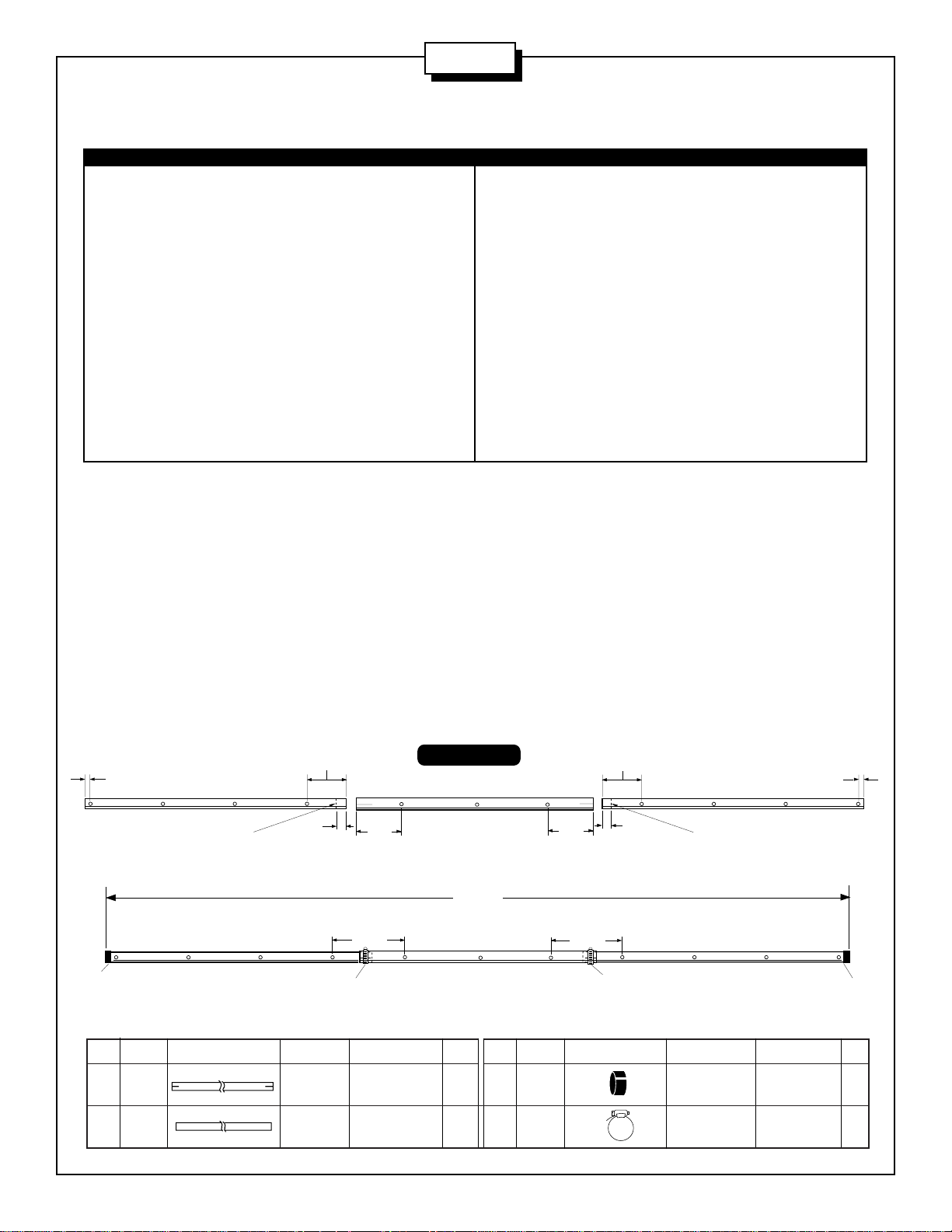
#1 - BOOM ASSEMBLY#1 - BOOM ASSEMBLY
#1 - BOOM ASSEMBLY
#1 - BOOM ASSEMBLY#1 - BOOM ASSEMBLY
Assemble the boom as shown below. Make a mark 1-3/4" (4.4 cm) in from the ends of the BB tubes as shown. Be sure to mark the correct end
of the tube. Slide worm clamps (410) onto the slotted ends of tube BA. Insert both BB tubes up to the marks you made. Align the element holes
and tighten the worm clamps. Push the end caps (61) onto the ends of the boom. The assembled boom is symmetrical so either end can be the
front.
14-1/4"
(36.2 cm)
6-1/4"
(15.7 cm)
1-3/4"
(4.44 cm)
410
BB
Make a mark here.
BB
CAP (2.2 cm)
CLAMP (2.5 cm)
7/8"
(2.2 cm)
61
6-1/4"
7/8"
(2.2 cm)
61
KEY P/N DISPLAY DESC SIZE QTY
BA ALUM 1" x 48" 1
BB ALUM 7/8" x 50" 2
BB
Make a mark here.
BB
(15.7 cm)
1-3/4"
(4.44 cm)
TUBE (2.5 x 122 cm)
TUBE (2.2 x 127 cm)
(36.2 cm)
410
9-3/4"
(24.8 cm)
14-1/4"
FIGURE A
BA
144-1/2"
(367 cm)
BA
KEY P/N DISPLAY DESC SIZE QTY
61 050061 PLASTIC 7/8" 2
410 030410 WORM 1" 2
9-3/4"
(24.8 cm)
2

A144-11
#2 - ELEMENT ASSEMBLY#2 - ELEMENT ASSEMBLY
#2 - ELEMENT ASSEMBLY
#2 - ELEMENT ASSEMBLY#2 - ELEMENT ASSEMBLY
Slide the four pieces of the Reddi-Match assembly (PT, RR, RT, 251) together (figure B). Slide the tuning strap (125) onto the driven element (EB)
and secure loosely with screws (79), nuts (11) and lock washers (41). Press on end caps (53). Slide the Reddi-Match assembly through the tuning
strap. Connect the flattened rod end to the screw on the connector bracket (CB) with nut (11) and washer (41). Attach the entire driven element
assembly shown below to the boom with hardware provided
referring to figure D for the proper location. Slide the poly tube
(PT) on the Reddi-Match assembly over the rod (RR) up to the
flattened end of that rod (figure B-2). Adjust to the dimensions
indicated and tighten all connections. Be sure that the connector is pointed towards the center of the boom and the ReddiMatch assembly is parallel to the element above.
Check all element lengths using table A. The cutting tolerance
on these elements is ±1/16" (.16 cm). The elements are
progressively shorter as you proceed toward the front end of
the boom. Attach each element to the boom per figure C
referring to figure D for proper location.
TABLE A
ELEMENT LENGTH
KEY NO. INCHES CM
EA 1 40-1/4 102.2
EB 2 38-7/16 97.6
EC 3 36-3/4 93.3
ED 4 36-1/4 92.1
EE 5 35-3/4 90.8
EF 6 35-1/4 89.5
EG 7 34-3/4 88.3
EH 8 34-1/4 87.0
EI 9 33-3/4 85.7
EJ 10 33-1/4 84.4
EK 11 32-3/4 83.2
KEY P/N DISPLAY DESC SIZE QTY
11 010011 SS 8-32 14
HEX NUT
26 190026 ALUMINUM 7/8" 11
BRACKET (2.2 cm)
28 190028 ALUMINUM 10
HALF WASHER
41 011941 SS LOCK #8 14
WASHER
53 050053 PLASTIC 1/2" 2
CAP (1.3 cm)
79 010079 SS MACHINE 8-32 x 1/2" 2
SCREW (1.3 cm)
120 010120 SS MACHINE 8-32 x 2" 1
SCREW (5.1 cm)
125 200125 TUNING 1
STRAP
231 010231 SS MACHINE 8-32 x 1-3/4" 10
SCREW (4.4 cm)
251 050251 PLASTIC 3/8" 1
CAP (.9 cm)
CB CONNECTOR 1
BRACKET
EB ALUMINUM 1/2 x 38-7/16" 1
TUBE (1.3 x 97.6 cm)
FIGURE B
53
BOOM
26
ELEMENT
28
KEY P/N DISPLAY DESC SIZE QTY
PT POLY 3/16" x 4-1/2" 1
RR REDDI-MATCH 3/16" x 4" 1
RT ALUMINUM 3/8" x 6-1/2" 1
EB
231
BOOM
C
e
n
te
r
o
f
A
n
te
n
n
a
11
41
26
120
CB
11
41
FIGURE B-2
11
Poly Tube
41
Poly tube on Reddi-Match
should be touching the
flared rod end.
125
"
8
/
)
3
-
m
5
c
5
6
.
3
1
(
41
"
4
/
)
3
m
c
9
.
11
1
(
Reddi-Match
PT
RR
53
79
251
RT
FIGURE C
TUBE (.5 x 11.4 cm)
ROD (.5 x 10.2 cm)
TUBE (.9 x 16.5 cm)
3

A144-11
3
EC
4
ED
1
EA
8
EH
7
EG
6
EF
5
EE
Direction of Maximum Signal
14-1/4"
(36.2 cm)
FRONT
9
EI
10
EJ
11
EK
2
EB
14-1/4"
(36.2 cm)
14-1/4"
(36.2 cm)
14-1/4"
(36.2 cm)
14-1/4"
(36.2 cm)
14-1/4"
(36.2 cm)
14-1/4"
(36.2 cm)
14-1/4"
(36.2 cm)
14-1/4"
(36.2 cm)
14-1/4"
(36.2 cm)
6-1/2"
(16.5 cm)
FIGURE D
#3 - MAST MOUNT#3 - MAST MOUNT
#3 - MAST MOUNT
#3 - MAST MOUNT#3 - MAST MOUNT
Mount the antenna to your mast using the mounting plate (70) and the
hardware provided per figure E. Refer to figure D for the balance point.
Tighten the U-bolts taking care not to crush the boom.
FIGURE E
KEY P/N DISPLAY DESC SIZE QTY
45 321045 ALUMINUM 1/2" x 1/2" 4
70 190070 FORMED 4" x 6" 1
84 010084 SS LOCK 1/4" 8
85 010085 SS HEX 1/4" 8
402 013402 SS FLAT 5/16" 4
326 290326 DANGER 1
401 010401 SS 3" x 1-3/4" 4
SPACER (1.3 x 1.3 cm)
MAST PLATE (10.1 x 15.2 cm)
WASHER (.63 cm)
NUT (.63 cm)
WASHER (.8 cm)
LABEL
U-BOLT (7.6 x 4.4 cm)
#4 - CONNECTOR ASSEMBLY#4 - CONNECTOR ASSEMBLY
#4 - CONNECTOR ASSEMBLY
#4 - CONNECTOR ASSEMBLY#4 - CONNECTOR ASSEMBLY
MAST
401
85
402
84
45
326
401
AA
70
401
85
84
84
85
This antenna is designed for use with 50 Ohm coaxial cable terminated with a PL-259 connector. Any length of feedline can be used with
your A144-11. The shortest length of cable will have the least loss. A connector boot is included for use with your new antenna. Slide
the boot over the cable before attaching your PL-259 (figure F). Spread silicone on the outer threads of the Reddi-Match and PL-259
connector. DO NOT COAT THE CENTER PINS OF THE PL-259. Attach the connector to the Reddi-Match. Apply the remaining silicone
to the outside of the connector. Slip the vinyl boot over the connector and against the mast bracket for a weather tight connection.
KEY P/N DISPLAY DESC SIZE QTY
115 050115 CONN 1
116 240116 SILICONE 1
cushcraft
SILICONE GREASE
BOOT
PACKAGE
COAT WITH SILICONE GREASE
cushcraft
FIGURE F
cushcraft
(DO NOT coat the center pin or socket!)
4

#5 - FEEDLINE#5 - FEEDLINE
#5 - FEEDLINE
#5 - FEEDLINE#5 - FEEDLINE
Tape your feedline along the boom and down
mast (figure G). Any length of feed line can be
used with your A144-11. The shortest length
cable will have the least loss.
FIGURE G
A144-11
Reddi-Match should be
pointed up and away
from mast!
#6 - STACKING OPTIONS#6 - STACKING OPTIONS
#6 - STACKING OPTIONS
#6 - STACKING OPTIONS#6 - STACKING OPTIONS
The A144-11 may be stacked in arrays for increased gain and improved
radiation patterns. When stacking two A144-11's use the A147-VPK
stacking kit, figure H. When stacking four antennas use two A147-22
antennas and one A147-SK harness, figure I.
DUAL STACKING KIT
A14-VPK
HARNESS ONLY
A147-SK
FIGURE H
7
6
"
(
1
9
3
c
m
)
(2) A147-22 & A147-SK HARNESS
QUAD ARRAY
FIGURE I
7
6
"
(
1
9
3
c
m
)
"
6
7
)
m
c
3
9
1
(
5
A144-11
SPECIFICATIONS
MODEL A144-11
Frequency, MHz 144-146
No. Elements 11
Forward Gain, dBd 13.2
Front to Back Ratio, dB 20
SWR 1.2:1 Typical
2:1 Bandwidth MHz >3
Power Rating, Watts PEP 1000
3 dB Beamwidth, Degrees
E Plane 38
LIMITED WARRANTY
Cushcraft Corporation, P.O. Box 4680, Manchester, New Hampshire 03108, warrants to the original consumer purchaser for one year
from date of purchase that each Cushcraft antenna is free of defects in material or workmanship. If, in the judgement of Cushcraft, any
such antenna is defective, then Cushcraft Corporation will, at its option, repair or replace the antenna at its expense within thirty days of
the date the antenna is returned (at purchasers expense) to Cushcraft or one of its authorized representatives. This warranty is in lieu of
all other expressed warranties, any implied warranty is limited in duration to one year. Cushcraft Corporation shall not be liable for any
incidental or consequential damages which may result from a defect. Some states do not allow limitations on how long an implied warranty
lasts or exclusions or limitations of incidental or consequential damages, so the above limitation and exclusion may not apply to you. This
warranty gives you specific legal rights, and you may also have other rights which vary from state to state. This warranty does not extend
to any products which have been subject to misuse, neglect, accident or improper installation. Any repairs or alterations outside of the
Cushcraft factory will nullify this warranty.
Boom Length, ft (m) 12 (3.6)
Longest Element, in(cm) 40 (101.6)
Turning Radius, ft (m) 6.75 (2.0)
Mast Size Range, in (cm) 1.25-1.5
(3.2-3.8)
Wind Load, ft2 (m2) 1.21 (0.11)
Weight, lb (kg) 6 (2.7)
48 PERIMETER ROAD, MANCHESTER, NH 03108
603-627-7877 / TELEX 4949472 / FAX 603-627-1764
SPECIFICATIONS SUBJECT TO CHANGE WITHOUT NOTICE
6
 Loading...