

Page 1

ASSEMBLY AND INSTALLATION
INSTRUCTIONS
13B2N
2 METER BROADBAND BOOMER
SSB/CW/FM YAGI
144-146 MHz
COMMUNICATIONS ANTENNAS
951700 (6/96)
Page 2
13B2N
THIS ANTENNA IS AN ELECTRICAL CONDUCTOR. CONTACT WITH POWER LINES CAN RESULT IN DEATH, OR SERIOUS INJURY.
DO NOT INSTALL THIS ANTENNA WHERE THERE IS ANY POSSIBILITY OF CONTACT WITH OR HIGH VOLTAGE ARC-OVER FROM
POWER CABLES OR SERVICE DROPS TO BUILDINGS. THE ANTENNA, SUPPORTING MAST AND/OR TOWER MUST NOT BE CLOSE
TO ANY POWER LINES DURING INSTALLATION, REMOVAL OR IN THE EVENT PART OF THE SYSTEM SHOULD ACCIDENTALLY
FALL. FOLLOW THE GUIDELINES FOR ANTENNA INSTALLATIONS RECOMMENDED BY THE U.S. CONSUMER PRODUCT SAFETY
COMMISSION AND LISTED IN THE ENCLOSED PAMPHLET.
Your Cushcraft 13B2N Boomer antenna is designed and manufactured to give trouble free service. This antenna will perform as specified if the
instructions and suggestions in this manual are followed and care is used in the assembly and installation. When checking the components received
in your antenna package use the parts listed beside each diagram. There is a master parts list on page 2. If you are unable to locate any tube or
component, check the inside of all tubing.
to verify the parts count. If you claim a missing part, you will be asked for the weight verification label.
IMPORTANT: Save the weight label from the outside of the carton. Each antenna is weighed at the factory
WARNING
PLANNING
Plan your installation carefully. If you use volunteer helpers be sure that they are qualified to assist you. Make certain that everyone involved
understands that you are the boss and that they must follow your instructions. If you have any doubts at all, employ a professional antenna
installation company to install your antenna.
LOCATION
Location of the antenna is very important. Surrounding objects such as trees, power lines, other antennas, etc. will seriously reduce efficiency. To
minimize the effects of surrounding objects, mount the antenna as high and in the clear as possible. If metal guy wires are used, they should be
broken with strain insulators. EXTREME CARE MUST BE USED FOR YOUR SAFETY. YOU MUST INSURE THAT WHILE THE 13B2N IS IN
OPERATION NEITHER PEOPLE OR PETS CAN COME IN CONTACT WITH ANY PORTION OF YOUR ANTENNA. DEADLY VOLTAGES AND
CURRENTS MAY EXIST. ALSO, SINCE THE EFFECTS OF EXPOSURE TO RF FIELDS ARE NOT FULLY UNDERSTOOD, LONG TERM
EXPOSURE TO INTENSE RF FIELDS IS NOT RECOMMENDED. THERE IS A WARNING STICKER WHICH MUST BE ATTACHED TO THE
BOOM AS SHOWN IN FIGURE E.
MOUNTING
The mast mount bracket will accommodate up to a 2" (5.1 cm) mast. A 1-1/2" OD (3.8 cm) or larger heavy wall tubing mast should be used. A good
heavy duty antenna rotator will provide the best service and longest life. Often it is desirable to mount several antennas on one mast. To keep
possible interaction to a minimum, place your antennas as far apart as you can. The 13B2N provides excellent gain, clean pattern and low VSWR
across the entire 2 meter band. It can be mounted either horizontally or vertically.
VERTICAL (FM): If you plan to mount the 13B2N for vertical polarization, best results can be obtained by mounting the antenna at the top of the
mast. Note that element #6 is 3" (7.6 cm) from the edge of the mast mounting plate as shown in Figure D.
side of the mast opposite from the mounting plate.
HORIZONTAL (CW/SSB): Mount your 13B2N horizontally and as high as possible, with the boom-to-mast plate between elements 6 and 7 as shown
in figure D.
A vertically polarized 13B2N will have a VSWR of under 2:1 from 144 to 146 MHz.
Install the 13B2N with the elements on the
SYSTEM GROUNDING
Direct grounding of the antenna, mast and tower is very important. This serves as protection from lightning strikes and static buildup, and from high
voltage which is present in the radio equipment connected to the antenna. A good electrical connection should be made to one or more ground rods
(or other extensive ground system) directly at the base of the tower or mast, using at least #10AWG ground wire and non-corrosive hardware. For
details and safety standards, consult the National Electrical Code. You should also use a coaxial lightning arrester. Cushcraft offers several different
models, such as LAC-1, LAC-2 and the LAC-4 series
.
ASSEMBLY
Assemble your antenna by following the directions and illustrations in steps 1 through 6. After the antenna is completely assembled, verify
dimensions and element spacings for accuracy. Then, return to the section below for final tuning.
TUNING PROCEDURE
The 13B2N does not normally require tuning after assembly. However, if you wish to check the VSWR before installation, please observe the
following procedures. To prevent detuning the antenna, it should be tuned in place or at least 7 feet (2.13 meters) above ground and clear of
surrounding objects. Keep all metal obstructions such as guy wires and other antennas at least 10 feet (3.05 m) away since they will nullify any
adjustment and degraded performance will result.
Run the coax cable from your transmitter to the area in which the antenna is going to be tested. The length of this cable or your feedline is not critical.
Connect a good quality VSWR bridge to the end of this cable. Connect a short length of cable [10 ft. (305 cm) or less] from the VSWR bridge to the
antenna. Set the transmitter to your center operating frequency. When you read VSWR, be sure you move far enough away from the antenna so that
your body does not effect the reading.
Measure the VSWR. If it is high, move both T-Match straps (125) by 1/4" (.6 cm) either inward or outward and check the VSWR. Both T-match
straps should be the same distance from the center of the driven element. If the VSWR improved, then continue moving the T-Match straps in the
same direction. If the VSWR deteriorated then move the T-Match straps in the opposite direction. Repeat this procedure until no further
improvement can be made. You have matched your antenna. Then tighten all connections on the T-Match driven element assembly. Tape the
feedline to the boom and mast as shown in figure G.
1
Page 3
13B2N
MASTER PARTS LIST
KEY P/N DESCRIPTION QTY
11 010011 8-32 stainless steel hex nut 22
26 190026 7/8" (2.2 cm) formed aluminum bracket 13
28 190028 Aluminum half washer 12
41 011941 No. 8 split lock washer 26
53 050053 1/2" (1.27 cm) black plastic cap 2
70 190070 4" x 6" (10.2 x 15.2 cm) formed mounting plate 1
77 050077 3/8" (.95 cm) black plastic cap 2
79 010079 8-32 x 1/2" (1.3 cm) stainless steel machine screw 4
84 010084 1/4" (.64 cm) stainless steel lock washer 4
85 010085 1/4" (.64 cm) stainess steel hex nut 4
104 010104 1/4" (.64 cm) stainless steel flat washer 4
115 050115 Vinyl Boot 1
116 240116 Silicone Package 1
118 010118 5/16" (.79 cm) stainless steel hex nut 4
119 010119 5/16" (.79 cm) stainless steel lock washer 4
120 010120 8-32 x 2" (5.1 cm) stainless steel machine screw 12
123 010123 8-32 x 1-1/2" (3.8 cm) stainless steel machine screw 3
125 200125 T-match strap 2
131 050131 1-1/8" (2.86 cm) black plastic cap 2
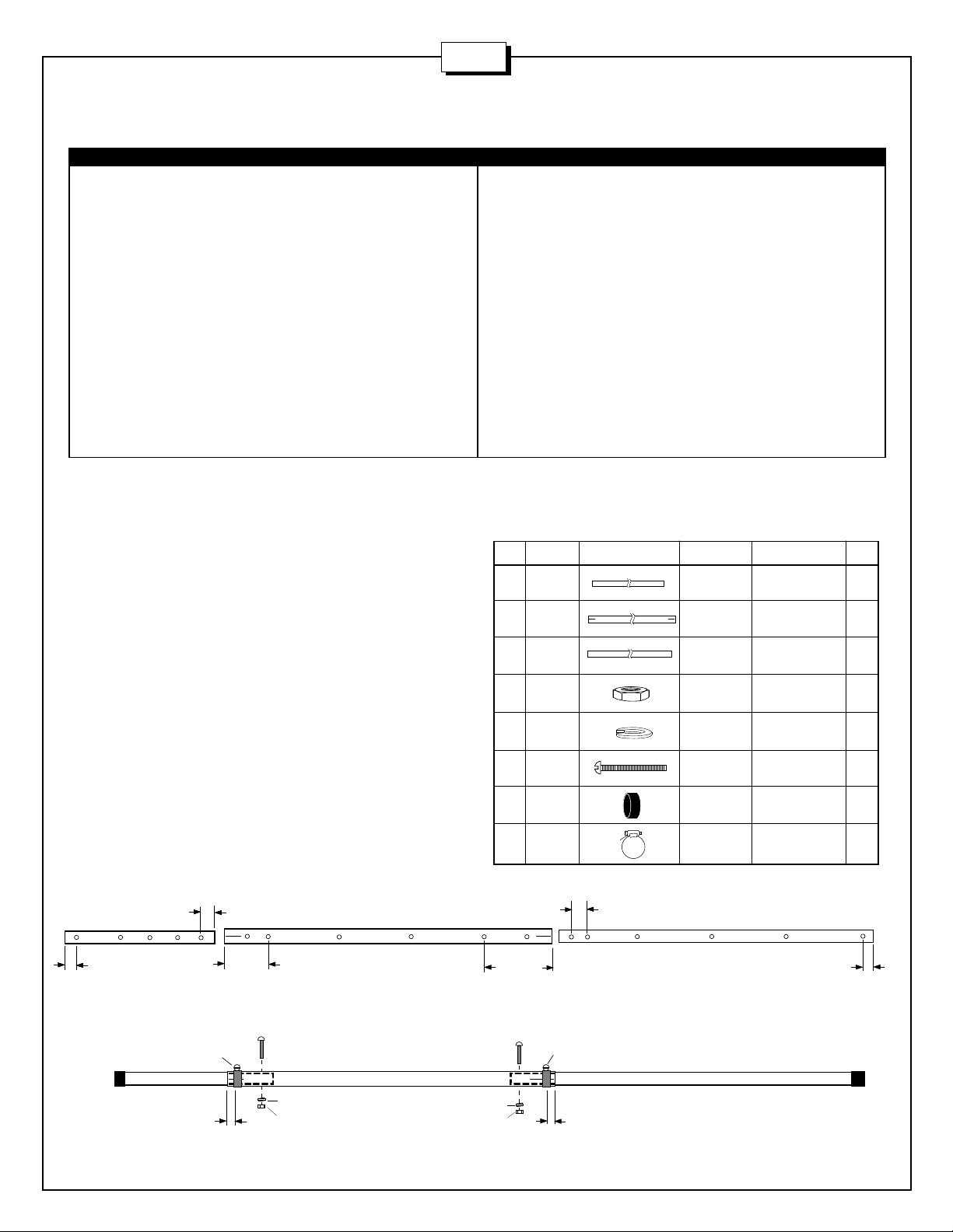
#1 - ASSEMBLE BOOM
Assemble the boom as shown below. Slide worm clamps (411) onto the
slotted ends of tube BB. Insert the end of tube BC into the end of tube
BB until the first set of drilled holes are aligned. Join booms with screw
(123), washer (41) and nut (11). Refer to the dimensions in figure A to
be sure that the proper tube ends are joined. Do the same with tube BA.
Tighten the screws and worm clamps. Push the end caps (131) onto the
ends of the boom.
FIGURE A
4-1/4"
BA
(10.8 cm)
BB
KEY P/N DESCRIPTION QTY
232 010232 8-32 x 2 -1/2" (6.4 cm) stainless steel machine screw 1
326 290326 Danger label 1
401 010401 1-1/2" x 3" (3.8 x 7.6 cm) stainless steel U-bolt 2
404 010404 2-1/2" x 3" (5.5 x 7.6 cm) stainless steel U-bolt 2
411 030411 1-3/8" (3.5 cm) stainless steel worm clamp 2
940 360940 No. 8 flat washer 1
BA 1-1/8" x 48" (2.9 x 121.9 cm) aluminum tubing 1
BB 1-1/4" x 72" (3.2 x 182.9 cm) aluminum tubing 1
BC 1-1/8" x 72" (2.9 x 182.9 cm) aluminum tubing 1
UM UM2N UltraMatch Balun 1
EA 39-3/4" (101 cm) aluminum rod 1
EB 1/2" x 38-7/8" (1.3 x 98.7 cm) aluminum tubing 1
EC 37 -7/8" (96.2 cm) aluminum rod 1
ED 36 -1/4" (92.1 cm) aluminum rod 2
EE 35 -3/4" (90.8 cm) aluminum rod 1
EF 35-1/4" (89.5 cm) aluminum rod 1
EG 34-5/8" (88 cm) aluminum rod 6
ET 3/8" x 6-1/2" (.95 x 16.5 cm) aluminum tubing 2
KEY P/N DESC. SIZE QTY
BA ALUM 1-1/8" x 48" 1
TUBING (2.9 x 121.9 cm)
BB ALUM 1-1/4" x 72" 1
TUBING (3.2 x 182.9 cm)
BC ALUM 1-1/8" x 72" 1
TUBING (2.9 x 182.9 cm)
11 010011 SS HEX 8-32 2
NUT
41 011941 SS LOCK #8 2
WASHER
123 010123 SS 8-32 x 1-1/2" 2
SCREW (3.8 cm)
131 050131 PLASTIC 1-1/8" 2
CAP (2.86 cm)
411 030411 SS WORM 1-3/8" 2
CLAMP (3.5 cm)
2-3/4"
(7 cm)
BC
1-1/2"
(3.8 cm)
131
411
BA
1/4" (.63 cm)
7-3/4"
(19.7 cm)
123
15-1/2"
(39.4 cm)
123
411
41
11
BB
41
11
1/4" (.63 cm)
BC
1-1/2"
(3.8 cm)
131
2
Page 4
13B2N
13B2N
#2 - ASSEMBLE T-MATCH
FIGURE B
26
11
41
79
53
KEY P/N DISPLAY DESC SIZE QTY
EB ALUM 1/2" x 38-7/8" 1
ET ALUM 3/8" x 6-1/2" 2
UM UM2N UltraMatch 1
11 010011 SS HEX 8-32 8
26 190026 ALUM 7/8" 1
41 011941 SS LOCK #8 10
53 050053 PLASTIC 1/2" 2
77 050077 PLASTIC 3/8" 2
79 010079 SS MACHINE 8-32 x 1/2" 4
123 010123 SS MACHINE 8-32x1-1/2 1
125 200125 T-MATCH 2
232 010232 SS MACHINE 8-32 x 2 1/2" 1
940 360940 ALUM FLAT #8 1
EB
125
77
ET
41
11
4-1/2"
(11.8 cm)
TUBING (1.3 x 98.7 cm)
TUBING (.95 x 16.5 cm)
BALUN
NUT
BRACKET (2.2 cm)
WASHER
CAP (1.27 cm)
CAP (.95 cm)
SCREW (1.3 cm)
SCREW (3.81)
STRAP
SCREW (6.4 cm)
WASHER
940
41
232
11
41
79
125
ET
4-1/2"
(11.8 cm)
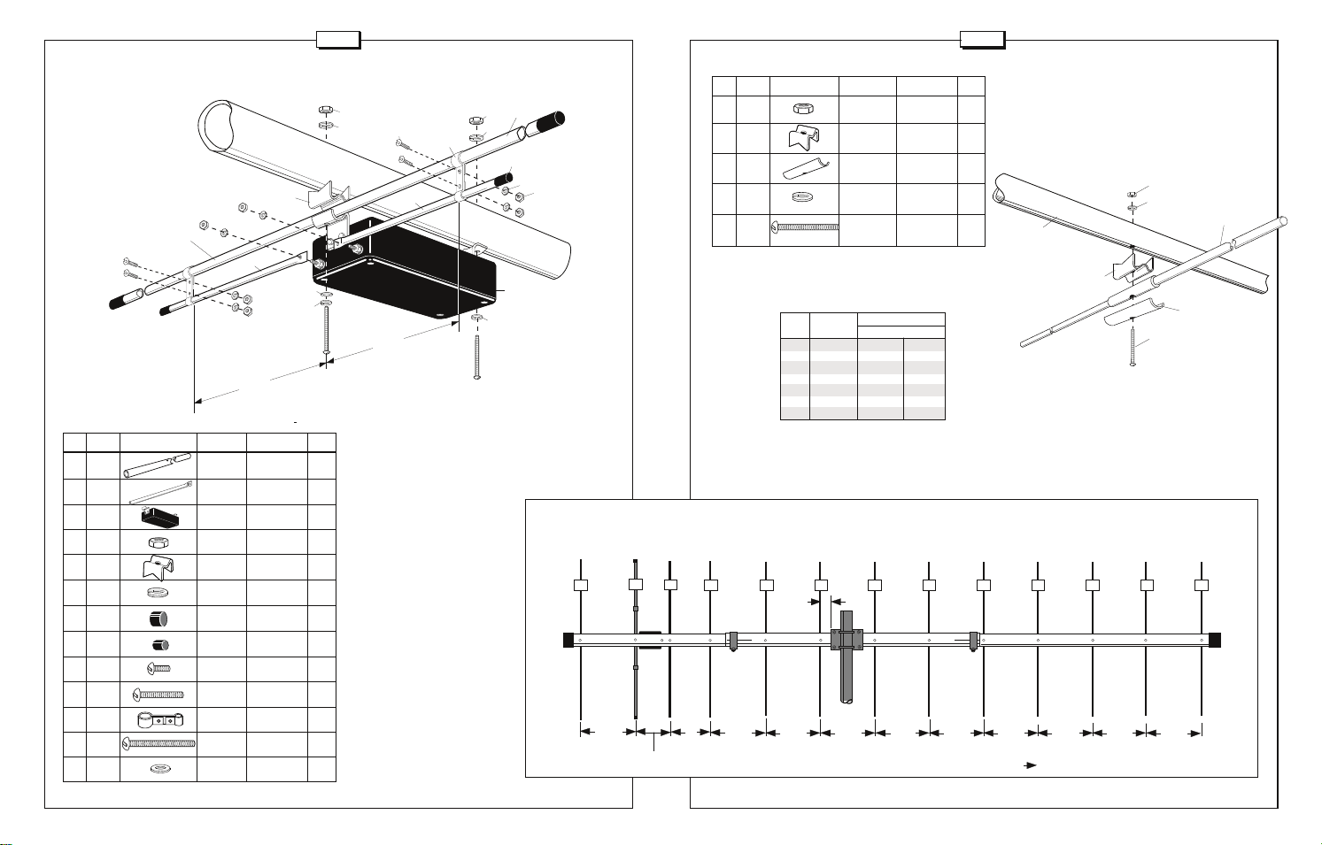
Assemble the T-match to the driven element (EB) as illustrated
in figure B. First attach the UltraMatch to the driven element with
the hardware shown. Then connect the T-match elements (ET)
to the UltraMatch with the split washers (41) and nuts (11). Next,
attach the T-match elements to the driven element with the Tmatch straps (125) and hardware shown
while noting the spacing dimensions
between the straps. Place plastic caps
(53) on the ends of the tube EB and plastic
caps (77) on the ends of the tubes ET.
Attach this subassembly to position 2 on
the boom as shown in figure D noting that
the UltraMatch feedpoint must face the
center of the antenna. Tighten all screws.
EB
11
41
77
41
11
UM
41
123
KEY P/N DISPLAY DESC SIZE QTY
11 010011 SS 8-32 12
53
26 190026 ALUMINUM 7/8" 12
28 190028 ALUMINUM 12
41 011941 SS LOCK #8 12
120 010120 SS MACHINE 8-32 x 2" 12
HEX NUT
BRACKET (2.2 cm)
HALF WASHER
WASHER
SCREW (5.1 cm)
TABLE A (Element Lengths)
Element Length
KEY No. INCHES CM
EA 1 39-3/4 101.0
EB 2 38-7/8 98.7
EC 3 37-7/8 96.2
ED 4,5 36-1/4 92.1
EE 6 35-3/4 90.8
EF 7 35-1/4 89.5
EG 8-13 34-5/8 88.0
#3 - MOUNT ELEMENTS
Attach the solid rod reflector and directors to the boom at the
locations shown on figure D. First check all element lengths using
table A. Group similar element lengths together. The elements
are progressively shorter as you proceed toward the front end of
the boom. Attach each element to the boom using the hardware
shown in figure C.
11
41
BOOM
26
120
ELEMENT
28
FIGURE C
FIGURE D
1
EA
2
EB
43
EC
ED EFED EE
131 131
15-1/2"
(39.4 cm)
8-11/16"
(22.1 cm)
9"
(22.9 cm)
14-7/8"
(37.8 cm)
5
(7.6 cm)
16-1/4"
(41.3 cm)
109876
11
1312
EG EG EG EG EG EG
3"
16-1/4"
(41.3 cm)
16-1/4"
(41.3 cm)
16-1/4"
(41.3 cm)
16-1/4"
(41.3 cm)
16-1/4"
(41.3 cm)
16-1/4"
(41.3 cm)
16-1/4"
(41.3 cm)
Direction of Maximum Signal
3
4
Page 5
13B2N
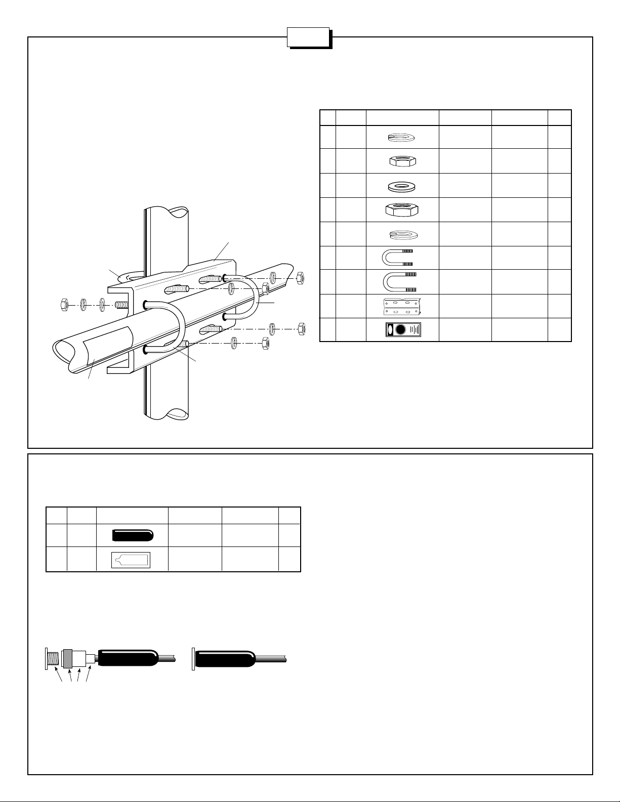
#4 - ASSEMBLE BOOM TO MAST MOUNT
Assemble and mount the boom to mast clamp bracket (70) between
elements 6 and 7 with the U-bolts 401 as shown in figure E. Secure with
flat washer (104), lock washer (84) and nut (85) in that order. Note that
the rear of the mast clamp must be 3 inches (7.6 cm) from element 6 as
shown on figure D. You are now ready to mount the antenna to your
mast using the U-bolts 404. Secure with lock washers (119) and nut
(118) in that order. Affix the warning label (326) to the boom as shown in
figure E.
FIGURE E
70
119
401
119
118
85
84
326
MAST
404
104
401
KEY P/N DISPLAY DESC SIZE QTY
84 010084 SS LOCK 1/4" 4
85 010085 SS HEX 1/4" 4
104 010104 SS FLAT 1/4" 4
118 010118 SS HEX 5/16" 4
119 010119 SS LOCK 5/16" 4
401 010401 SS 1 1/2" x 3" 2
404 010404 SS 2 1/2" x 3" 2
70 190070 MOUNTING 4" x 6" 1
118
326 290326 DANGER 1
WASHER (.64 cm)
NUT (.64 cm)
WASHER (.64 cm)
NUT (.79 cm)
WASHER (.79 cm)
U-BOLT (3.8 x 7.6 cm)
U-BOLT (5.5 x 7.6 cm)
PLATE (10.2 x 15.2 cm)
LABEL
#5 - CONNECTOR ASSEMBLY
KEY P/N DISPLAY DESC SIZE QTY
115 050115 CONNECTOR 1
116 240116 SILICONE 1
COAT WITH SILICONE GREASE
(DO NOT coat the center pin or socket!)
cushcraft
SILICONE GREASE
FIGURE F
cushcraft
BOOT
PACKAGE
cushcraft
The antenna is designed for use with 50 Ohm coaxial cable terminated
with an N connector. Any length of feedline can be used with your 13B2N.
The shortest length of cable will have the least loss. A connector boot is
included for use with your new antenna. A connector boot is included with
your new antenna. Slide the boot over the cable before attaching your N
connector (figure F). Spread silicone on the outer threads of the
UltraMatch and N connector.
THE N CONNECTOR OR THE ULTRAMATCH SOCKET.
connector to the UltraMatch. Apply the remaining silicone to the outside
of the connector and against the mast bracket for a weather tight
connection.
DO NOT COAT THE CENTER PINS OF
Attach the
5
Page 6
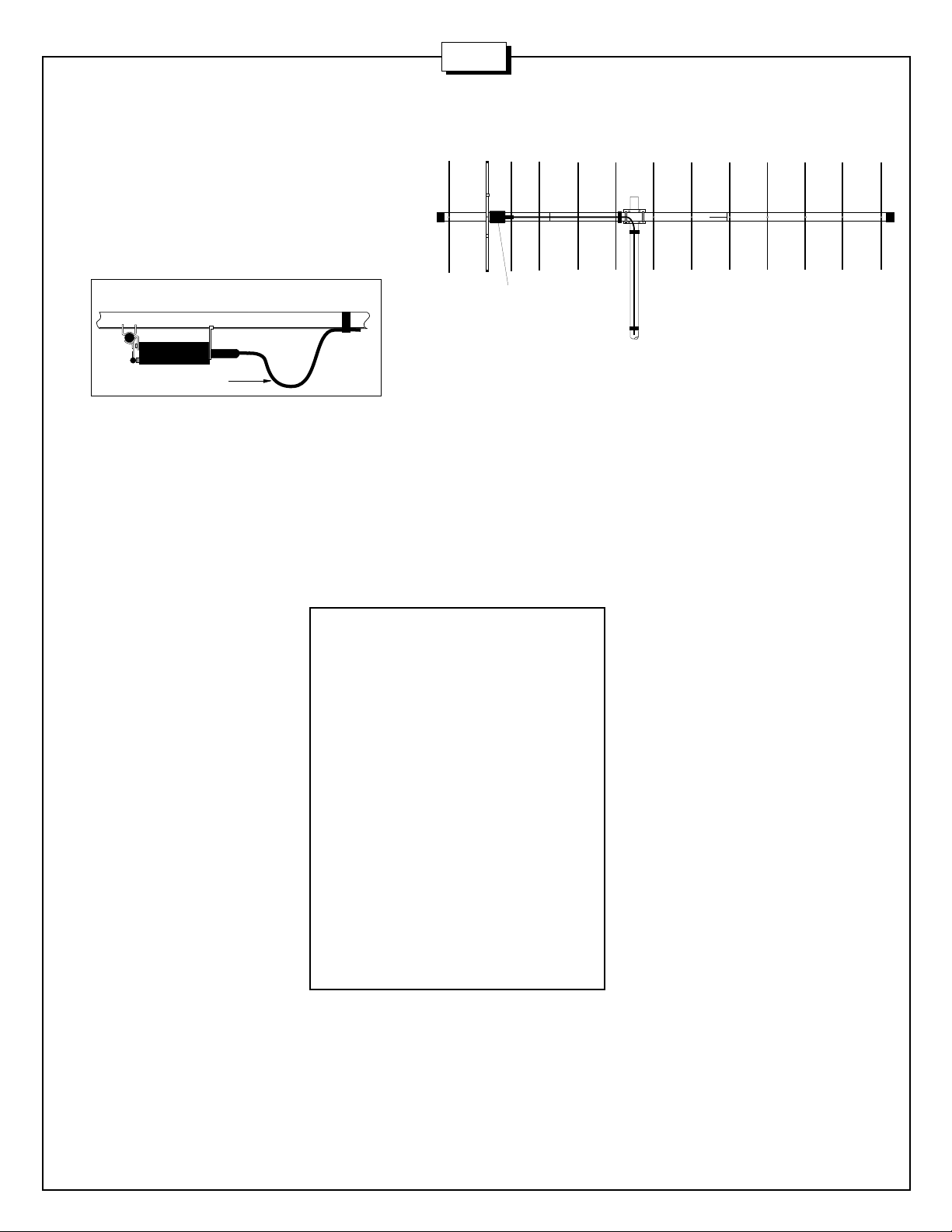
#6 - FEEDLINE ATTACHMENT
UltraMatch
Tape your feedline down the boom and mast. If you choose
horizontal polarization, it's a good idea to form a drip loop in the
coax to help protect the connector from water damage (figure G.)
If you choose vertical polarization, bring the feedline all the way
down the boom until you come to the mast, then bring the
feedline straight down the mast (figure H).
FIGURE G
DRIP LOOP
13B2N
FIGURE H
SPECIFICATIONS
Frequency, MHz
No. Elements
Forward Gain, dBd
Front to Back Ratio, dB
SWR 1.2:1 Typical
2:1 Bandwidth, MHz
Power Rating, Watts PEP
3 dB Beamwidth, Degrees
E Plane
H Plane
Side Lobe Attenuation,
dB, E Plane
Electical Wavelength
Longest Element, in (cm)
Turning Radius, ft (m)
Mast Size Range, in (cm)
Wind Load, ft2 (m2)
Weight, lb (kg)
144-146
13
15.8
26
>4
2000
2 x 18
2 x 19
>60
2.2
39.75 (101)
8.9 (2.7)
1.5-2
(3.8-5.1)
1.8 (.17)
6.7 (3.1)
6
Page 7

13B2N
Cushcraft Corporation, P.O. Box 4680, Manchester, New Hampshire 03108, warrants to the original consumer purchaser for one year from date of
purchase that each Cushcraft antenna is free of defects in material or workmanship. If, in the judgement of Cushcraft, any such antenna is defective,
then Cushcraft Corporation will, at its option, repair or replace the antenna at its expense within thirty days of the date the antenna is returned (at
purchasers expense) to Cushcraft or one of its authorized representatives. This warranty is in lieu of all other expressed warranties, any implied warranty
is limited in duration to one year. Cushcraft Corporation shall not be liable for any incidental or consequential damages which may result from a defect.
Some states do not allow limitations on how long an implied warranty lasts or exclusions or limitations of incidental or consequential damages, so the
above limitation and exclusion may not apply to you. This warranty gives you specific legal rights, and you may also have other rights which vary from
state to state. This warranty does not extend to any products which have been subject to misuse, neglect, accident or improper installation. Any repairs
or alterations outside of the Cushcraft factory will nullify this warranty.
LIMITED WARRANTY
COMMUNICATIONS ANTENNAS
48 PERIMETER ROAD, MANCHESTER, NH 03108 USA
603-627-7877 • FAX 603-627-1764
SPECIFICATIONS SUBJECT TO CHANGE WITHOUT NOTICE
 Loading...