

Page 1

CNS4 CSfC
Common Airborne Recorder
CSfC Encrypted Data Storage
User Guide
Part Number: DDOC0108-000-A2
Page 2

This Page Intentionally Left Blank
Page 3
User Guide DDOC0108-000-A2
Front Matter
Revisions
Document
Number Media Revision Date Description PCN
DDOC0108-000 PDF A0 02/12/19 NIAP Review NA
DDOC0108-000 PDF A0.1 02/12/19 Incorporate Gossamer comments NA
DDOC0108-000 PDF A1 03/06/19 Initial Release 0319-0001
DDOC0108-000 PDF A2 03/20/19 Change nomenclature to CNS4 CSfC 0319-0002
NOTE
The content revision level remains unchanged for chapters / appendices impacted only by nomenclature change (implemented by revision A2).
The Curtiss-Wright CNS4 CSfC DDOC0108-000-A2 User Guide is made up of the following
individual chapters / appendices:
Chapter / Appendix Topic Content Revision
1.0 Introduction 0.0
2.0 Overview 1.0
3.0 Controls and Indicators 0.0
4.0 Installation 1.0
5.0 Quick Start 1.0
6.0 Operation 1.0
7.0 System Configuration 0.0
8.0 Troubleshooting 0.0
9.0 Simple Network Management Protocol 0.0
10.0 Remove / Replace 2.0
11.0 Command Line Interface 0.0
A Specifications 0.0
B Cables / Connectors 0.0
C Ordering Information 1.0
Changes to content are shown through the use of change bars placed in the left margin next to the
changed material.
CNS4 CSfC i
Page 4
User Guide DDOC0108-000-A2
Safety
WARNING
HAZARD. A potential hazard that could result in serious injury or death.
Information contained in WARNINGS applies to dangers and hazards that may result in injury and
/ or death to personnel. The actual hazard is provided in CAPITALIZED letters and the information
that mitigates the danger is provided in sentence case. This information typically precedes
procedural steps. It also may be present in narrative text to warn operators or maintenance
personnel of dangers present in the equipment.
CAUTION
HAZARD. A potential hazard that could result in equipment damage or improper operation.
Information contained in CAUTIONS applies to dangers and hazards that may result in damage to
equipment or improper operation. The actual hazard is provided in CAPITALIZED letters and the
information that mitigates the danger is provided in sentence case. This information typically
precedes procedural steps. It also may be present in narrative text to warn operators or
maintenance personnel of dangers present in the equipment.
NOTE
Amplifying information that helps in making a task of procedure more easily understood.
NOTES are used to supply amplifying information that will result in ease of testing or be beneficial
to personnel. This information typically precedes procedural steps. It also may be present in
narrative text as well.
Style and Conventions
This user guide uses the following typographical conventions.
This style Refers to
Ready
go
NTER Special keys on the keyboard, such as enter, alt, and spacebar.
E
Save Software command buttons and sections of dialog boxes, such as
File Open A menu and a specific menu command.
LT+F1 Pressing more than one key at the same time.
A
ALT, TAB Pressing more than one key in sequence.
xx,yy Variable in error messages and text.
jobfile.dat File names.
xyz
Text the software displays.
Anything you type, exactly as it appears, whether referenced in text or
at a prompt.
group boxes, text boxes, and text fields.
Denotes the result of an action or procedure.
Hyperlink.
STOP Controls on equipment.
CNS4 CSfC ii
Page 5

CNS4 CSfC User Guide
Table of Contents
Table of Contents
Introduction
1.1 Purpose ..................................................................................................................................................... 1-1
1.2 Scope ........................................................................................................................................................ 1-1
1.3 Quality Assurances.................................................................................................................................... 1-2
1.4 Related Information ................................................................................................................................... 1-2
1.5 Technical Support...................................................................................................................................... 1-2
1.6 Ordering Process....................................................................................................................................... 1-3
Overview
2.1 Description................................................................................................................................................. 2-1
2.1.1 Chassis ........................................................................................................................................... 2-1
2.1.2 FSM-C Module ................................................................................................................................ 2-3
2.1.3 ILE Module ...................................................................................................................................... 2-4
2.2 CNS4 Features.......................................................................................................................................... 2-6
2.3 Protocols.................................................................................................................................................... 2-7
2.4 CSfC Encryption ........................................................................................................................................ 2-7
2.4.1 Hardware Layer Encryption ............................................................................................................. 2-7
2.4.1.1 Hardware Layer Account Creation ........................................................................................ 2-7
2.4.1.2 Hardware Layer Account Log In ............................................................................................ 2-8
2.4.2 Software Layer Encryption .............................................................................................................. 2-9
Controls and Indicators
3.1 CNS4 Chassis Controls / Indicators .......................................................................................................... 3-1
3.1.1 Chassis LED Brightness ................................................................................................................. 3-1
3.2 ILE Module Controls / Indicators ............................................................................................................... 3-1
3.3 FSM-C Module Controls / Indicators ......................................................................................................... 3-2
Installation
4.1 Package..................................................................................................................................................... 4-1
4.2 Inspection .................................................................................................................................................. 4-1
4.3 Mounting.................................................................................................................................................... 4-2
4.3.1 Mounting - User Defined ................................................................................................................. 4-2
4.3.2 Mounting - ARINC Tray ................................................................................................................... 4-2
4.4 CNS4 Install / Remove .............................................................................................................................. 4-2
4.4.1 Install (User Defined Mount) ........................................................................................................... 4-2
4.4.2 Install (ARINC Tray) ........................................................................................................................ 4-3
4.4.3 Remove (User Defined Mount) ....................................................................................................... 4-3
4.4.4 Remove (ARINC Tray) .................................................................................................................... 4-3
4.5 Cables ....................................................................................................................................................... 4-4
4.5.1 Power / RS-232 Cable .................................................................................................................... 4-5
4.5.2 Ethernet Cable ................................................................................................................................ 4-5
Quick Start
5.1 Connections and Controls ......................................................................................................................... 5-1
5.2 Communications Setup ............................................................................................................................. 5-1
5.3 Login..........................................................................................................................................................5-1
DD0C0108-000-A2 iii
Page 6

CNS4 CSfC User Guide
Table of Contents
5.3.1 CNS4 ............................................................................................................................................... 5-1
5.4 Hardware Layer ......................................................................................................................................... 5-1
5.5 Software Layer .......................................................................................................................................... 5-1
5.6 Partition Disks............................................................................................................................................ 5-1
5.6.1 Erase All Partitions / All Slots .......................................................................................................... 5-1
5.6.2 Check Drive Status ......................................................................................................................... 5-1
5.6.3 Create Single Partition on FSM0 ..................................................................................................... 5-2
5.6.4 Create Single Partition on FSM1 ..................................................................................................... 5-2
5.6.5 Create Single Partition on FSM2 ..................................................................................................... 5-3
5.6.6 Create Single Partition on FSM3 ..................................................................................................... 5-4
5.6.7 Create NAS Partitions on FSM0 - 3 ................................................................................................ 5-4
5.7 Create Software Encryption Containers on FSM2 and FSM3 ................................................................... 5-5
5.8 Open Software Encryption Containers on FSM2 and FSM3 ..................................................................... 5-6
5.8.0.1 Method 1 ................................................................................................................................ 5-6
5.8.0.2 Method 2 ................................................................................................................................ 5-7
5.9 Format / Mount NAS Partitions.................................................................................................................. 5-8
5.10 Unformat NAS Partitions ......................................................................................................................... 5-9
5.11 Close Software Encryption Containers.................................................................................................... 5-9
5.12 Erase Software Encryption Containers.................................................................................................. 5-10
5.13 ILE Account Logout ............................................................................................................................... 5-11
5.14 Access from Windows as NAS Device .................................................................................................. 5-11
5.15 Access from Linux as NAS Device ........................................................................................................ 5-12
5.16 External Key Passing Example ............................................................................................................. 5-12
Operation
6.1 Lab Setup / Connections ........................................................................................................................... 6-1
6.2 Basic Operation ......................................................................................................................................... 6-2
6.2.1 Initial Configuration ......................................................................................................................... 6-2
6.2.1.1 Time ....................................................................................................................................... 6-2
6.2.1.2 Passwords ............................................................................................................................. 6-2
6.2.2 Communications ............................................................................................................................. 6-2
6.2.2.1 Terminal Emulation ................................................................................................................ 6-3
6.2.2.2 Ethernet ................................................................................................................................. 6-4
6.2.3 Account Management ..................................................................................................................... 6-5
6.2.4 Storage Media ................................................................................................................................. 6-5
6.2.4.1 Preparation ............................................................................................................................ 6-5
6.2.4.2 Assigning Services to Partitions ............................................................................................ 6-5
6.2.4.3 Preparation ............................................................................................................................ 6-5
6.2.4.4 Creating a RAID .................................................................................................................... 6-6
6.2.4.5 Partitioning ............................................................................................................................. 6-6
6.2.4.6 Assign NAS Service .............................................................................................................. 6-6
6.2.4.7 Format Partitions ................................................................................................................... 6-7
6.2.4.8 Mounting NAS Partition ......................................................................................................... 6-7
6.2.4.9 Verification ............................................................................................................................. 6-7
6.2.5 Health .............................................................................................................................................. 6-7
6.2.6 Built-In Test ..................................................................................................................................... 6-8
6.2.6.1 CBIT (Continuous Built-In Test) ............................................................................................. 6-8
6.2.6.2 IBIT (Initiated Built-In Test) .................................................................................................... 6-8
6.2.6.3 PBIT (Power-On Built In Test ................................................................................................ 6-9
DD0C0108-000-A2 iv
Page 7

CNS4 CSfC User Guide
Table of Contents
6.3 Update ....................................................................................................................................................... 6-9
6.3.1 CNS4 Operating System Update .................................................................................................... 6-9
6.3.2 ILE Module Firmware .................................................................................................................... 6-10
6.4 Encryption................................................................................................................................................ 6-11
6.4.1 Zeroize .......................................................................................................................................... 6-11
6.4.2 Hardware Encryption Layer ........................................................................................................... 6-12
6.4.2.1 LE Account - Internal / External Key Storage ...................................................................... 6-12
6.4.2.2 Internal Security Mode ......................................................................................................... 6-13
6.4.2.3 External Security Mode ....................................................................................................... 6-13
6.4.2.4 ILE Account Creation ........................................................................................................... 6-13
6.4.2.5 ILE Login ............................................................................................................................. 6-14
6.4.2.6 Key Transfer ........................................................................................................................ 6-14
6.4.3 Software Encryption ...................................................................................................................... 6-15
6.4.3.1 Software Encryption Container ............................................................................................ 6-15
System Configuration
7.1 add............................................................................................................................................................. 7-2
7.2 all ............................................................................................................................................................... 7-2
7.3 file .............................................................................................................................................................. 7-3
7.4 format ........................................................................................................................................................ 7-3
7.5 free ............................................................................................................................................................ 7-4
7.6 fsck ............................................................................................................................................................ 7-4
7.7 fsep............................................................................................................................................................7-5
7.8 getDevName.............................................................................................................................................. 7-5
7.9 getFreeDisks ............................................................................................................................................. 7-5
7.10 getNfsOpt ................................................................................................................................................ 7-5
7.11 help..........................................................................................................................................................7-6
7.12 hide..........................................................................................................................................................7-6
7.13 iscsi0, 1, 2, 3............................................................................................................................................ 7-6
7.14 isMounted ................................................................................................................................................ 7-7
7.15 mount....................................................................................................................................................... 7-7
7.16 multi ......................................................................................................................................................... 7-8
7.17 nas........................................................................................................................................................... 7-8
7.18 numFreeDisks ......................................................................................................................................... 7-9
7.19 numFsmDisks.......................................................................................................................................... 7-9
7.20 numPartitions........................................................................................................................................... 7-9
7.21 part .......................................................................................................................................................... 7-9
7.22 raid......................................................................................................................................................... 7-10
7.23 raidStatus .............................................................................................................................................. 7-10
7.24 remove................................................................................................................................................... 7-11
7.25 rescan.................................................................................................................................................... 7-11
7.26 scan ....................................................................................................................................................... 7-11
7.27 setNfsOpt............................................................................................................................................... 7-12
7.28 status ..................................................................................................................................................... 7-12
7.29 sw .......................................................................................................................................................... 7-13
7.30 trim......................................................................................................................................................... 7-13
7.31 umount................................................................................................................................................... 7-14
7.32 verb........................................................................................................................................................ 7-14
7.33 version ................................................................................................................................................... 7-14
DD0C0108-000-A2 v
Page 8

CNS4 CSfC User Guide
Table of Contents
7.34 wipe ....................................................................................................................................................... 7-14
7.35 wrap....................................................................................................................................................... 7-15
7.36 writecfg .................................................................................................................................................. 7-15
Troubleshooting
8.1 LED Indicators ........................................................................................................................................... 8-1
8.2 Error Codes ............................................................................................................................................... 8-1
Simple Network Management Protocol
9.1 SNMP MIB................................................................................................................................................. 9-3
Remove / Replace
10.1 ILE Module - Install / Remove ............................................................................................................... 10-1
10.1.1 Remove ....................................................................................................................................... 10-1
10.1.2 Install ........................................................................................................................................... 10-1
10.2 FSM-C Module - Install / Remove ......................................................................................................... 10-2
10.2.1 Remove ....................................................................................................................................... 10-2
10.2.2 Install ........................................................................................................................................... 10-3
10.3 Chassis Battery Replacement ............................................................................................................... 10-3
10.3.1 Remove ....................................................................................................................................... 10-3
10.3.2 Install ........................................................................................................................................... 10-4
10.4 ILE Module Battery Replacement.......................................................................................................... 10-4
10.4.1 Remove ....................................................................................................................................... 10-4
10.4.2 Install ........................................................................................................................................... 10-4
Command Line Interface
11.1 CLI Commands...................................................................................................................................... 11-1
11.1.1 CNS4 Commands ....................................................................................................................... 11-1
11.1.2 FSM-C Module Commands ......................................................................................................... 11-1
11.1.3 ILE Commands ........................................................................................................................... 11-1
11.2 Commands ............................................................................................................................................ 11-1
Specifications
A.1 Envelope / Mounting Dimensions..............................................................................................................A-1
A.2 Physical Dimensions / Weight...................................................................................................................A-3
A.3 Power Dissipation .....................................................................................................................................A-3
A.4 Electrical Requirements ............................................................................................................................A-3
A.5 Mean Time Between Failure .....................................................................................................................A-3
A.6 Environment ..............................................................................................................................................A-3
A.6.1 Temperature ...................................................................................................................................A-3
A.6.2 Humidity ..........................................................................................................................................A-3
A.6.3 Vibration, Operating ........................................................................................................................A-3
A.7 EMI............................................................................................................................................................A-3
Cables / Connectors
B.1 Power / RS-232.........................................................................................................................................B-1
B.2 Ethernet.....................................................................................................................................................B-2
Ordering Information
DD0C0108-000-A2 vi
Page 9

CNS4 CSfC User Guide
List of Figures
List of Figures
Figure 1.1 CNS4 CSfC CAR LRU..................................................................................................................... 1 - 1
Figure 2.1 CNS4 Assembly............................................................................................................................... 2 - 2
Figure 2.2 FSM-C Module Block Diagram ........................................................................................................ 2 - 3
Figure 2.3 FSM-C Module................................................................................................................................. 2 - 4
Figure 2.4 ILE Module Block Diagram .............................................................................................................. 2 - 5
Figure 2.5 ILE Module....................................................................................................................................... 2 - 5
Figure 2.6 Hardware Layer Account Creation................................................................................................... 2 - 8
Figure 2.7 Hardware Layer Account Log In ...................................................................................................... 2 - 8
Figure 3.1 CNS4 Chassis Indicators................................................................................................................. 3 - 1
Figure 3.2 ILE Module Controls / Indicators...................................................................................................... 3 - 2
Figure 3.3 FSM-C Module Controls / Indicators................................................................................................ 3 - 2
Figure 4.1 Anti-Tamper Label Locations........................................................................................................... 4 - 1
Figure 4.2 Required Door Clearance ................................................................................................................ 4 - 2
Figure 4.3 CNS4 Mounting - ARINC Tray......................................................................................................... 4 - 3
Figure 4.4 CNS4 Installed on ARINC Tray ....................................................................................................... 4 - 4
Figure 4.5 CNS4 Connectors............................................................................................................................ 4 - 4
Figure 4.6 Power / RS-232 Lab Cable.............................................................................................................. 4 - 5
Figure 4.7 Ethernet Lab Cable.......................................................................................................................... 4 - 5
Figure 6.1 CNS4 Test Setup............................................................................................................................. 6 - 1
Figure 6.2 PuTTY Terminal Emulator ............................................................................................................... 6 - 3
Figure 6.3 PuTTY Terminal Emulator (SSH) .................................................................................................... 6 - 4
Figure 6.4 CNS Update Utility......................................................................................................................... 6 - 10
Figure 6.5 ILE Firmware Update..................................................................................................................... 6 - 11
Figure 9.1 OID Tree .......................................................................................................................................... 9 - 1
Figure 10.1 ILE Module Replacement .............................................................................................................. 10 - 1
Figure 10.2 FSM-C Module Replacement ........................................................................................................ 10 - 2
Figure 10.3 Chassis Battery Replacement ....................................................................................................... 10 - 3
Figure 10.4 ILE Module Battery Replacement .................................................................................................. 10 - 5
Figure A.1 CNS4 Envelope/ Mounting Dimensions........................................................................................... A - 1
Figure B.1 Power / RS-232 Lab Cable.............................................................................................................. B - 1
Figure B.2 CNS4 Bulkhead Power Connector .................................................................................................. B - 1
Figure B.3 Ethernet Lab Cable.......................................................................................................................... B - 2
Figure B.4 CNS4 Bulkhead Ethernet Connectors ............................................................................................. B - 2
DDOC0108-000-A2 vii
Page 10

CNS4 CSfC User Guide
List of Tables
List of Tables
Table 6.1 Ethernet Interfaces ................................................................................................................................ 6-3
Table 6.2 Security Modes.................................................................................................................................... 6 -12
Table 7.1 Sysconfig Flags and Options................................................................................................................. 7 -1
Table 8.1 LED Indicators ....................................................................................................................................... 8-1
Table 8.2 Error Code List ...................................................................................................................................... 8 -1
Table B.1 Power / RS-232 Lab Cable Pinout ........................................................................................................ B -1
Table B.2 Ethernet Lab Cable Pinout .................................................................................................................... B-2
Table C.1 Ordering Information ............................................................................................................................. C- 1
DDOC0108-000-A2 viii
Page 11
User Guide DDOC0108-000-A2
DDOC0108-0001
FSM-C Modules
ILE Module
CNS4 Chassis
Introduction
1.1 Purpose
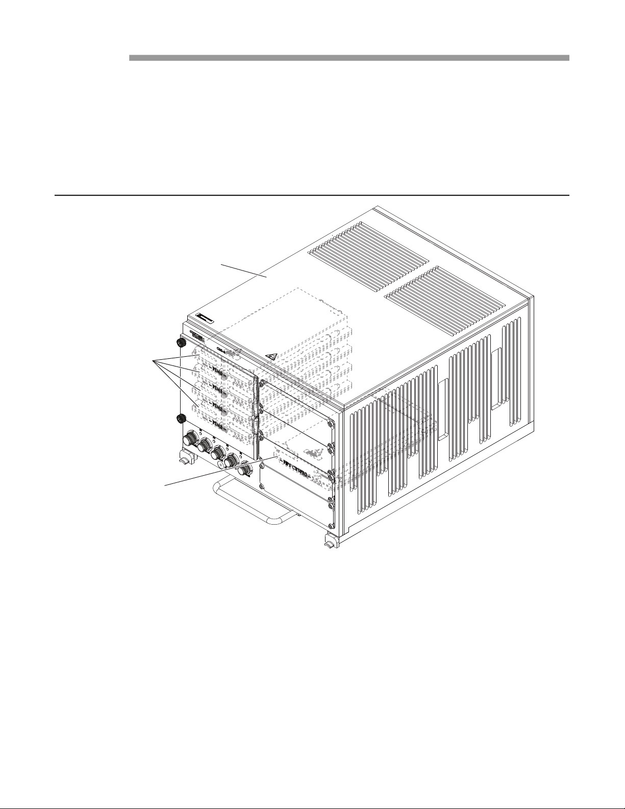
The purpose of this manual is to describe the Curtiss-Wright CNS4 CSfC Common Airborne
Recorder (CAR) Line Replaceable Unit (LRU) and to guide users through the process of
unpacking, installing, configuring, and using the unit. The CNS4 CSfC (Figure 1.1) requires the
use of multiple Flash Storage Modules-Carriers (FSM-C) and an In-Line Encryptor (ILE) to
operate. From this point forward, the product will be referred to as the CNS4; the associated
storage modules as FSM-C modules; and the associated encryptor module as the ILE module.
Figure 1.1 CNS4 CSfC CAR LRU
1.2 Scope
The information in this user guide is intended for information systems personnel, systems
coordinators, or highly skilled network users. This manual contains the following information:
• An overview of the CNS4.
• Unpacking, installation, and setup information.
• User interface connections.
• User input.
• Configuration options.
• Product specifications.
• Operation requirements.
• Environmental restrictions.
• Connector pinout and specifications.
• Ordering information for related products and parts
CNS4 CSfC 1 - 1 Introduction
Revision 0.0
Page 12

User Guide DDOC0108-000-A2
1.3 Quality Assurances
Curtiss-Wright Controls, Inc., Electronic Systems is committed to leveraging our technology
leadership to deliver products and services that meet or exceed customer requirements. In
addition to the physical product, the company provides documentation, sales and marketing
support, hardware and software technical support, and timely product delivery. Our quality
commitment begins with product concept and continues after receipt of the purchased product.
Curtiss-Wright Controls, Inc., Electronic Systems' Quality Management System is accredited to the
latest revision of the aerospace standard, AS9100 Quality Management Systems - Requirements
for Aviation, Space, and Defense Organizations.
Our Quality System addresses the following basic objectives:
• Achieve, maintain, and continually improve the quality of our products and service through
established design, test, production and service procedures.
• Improve the quality of our operations to meet the needs of our customers, suppliers, and other
stakeholders.
• Provide our employees with the tools and overall work environment to fulfill, maintain, and
improve product and service quality.
• Ensure our customer and other stakeholders that only the highest quality product or service
will be delivered.
Eagle Registrations Inc. assessed Curtiss-Wright's Quality Management System and confirmed
conformance to AS9100D including ISO 9001:2015 with Certificate No. 5819. The scope of the
registration is as follows: "Design, manufacture, test and repair of board level products, electronic
sub-systems, related software and services for commercial, aerospace and military applications.”
Customer feedback is integral to our quality and reliability program. We encourage customers to
contact us with questions, suggestions, or comments regarding any of our products or services.
We guarantee professional and quick responses to your questions, comments, or problems.
1.4 Related Information
• AES (Advanced Encryption Standard). https://csrc.nist.gov/publications/fips/fips197/ fips-
197.pdf
• EIA-232 RS-232 electrical characteristics single-ended voltage digital interface circuit.
http://www.eia.org/
• VITA 46, 47, 48, and 58. http://www.vita.com/vso-stds.html
• FIPS 140-2. https://csrc.nist.gov/publications/fips/fips197/ fips-197.pdf
• EMI Mil-Std-461
• NAS, http://www.pdl.cmu.edu/PDL-FTP/NASD/hotnet99.pdf
• Ruggedization, Curtiss-Wright, http://www.cwcelectronicsystems.com
• Curtiss-Wright Defense Solutions http://www.cwcdefense.com
• PuTTy User Manual (client program for SSH, Telnet, and Rolgin network protocols)
• Technical Note 8004 CNS4 CSfC Software and Firmware History
• NSA CSfC Program https://www.iad.gov/iad/programs/iad-initiatives/commercialsolutionsfor-
classified.cfm
1.5 Technical Support
Technical documentation is provided with all of our products. This documentation describes the
technology, its performance characteristics, and includes some typical applications. It also
includes comprehensive support information, designed to answer any technical questions that
might arise concerning the use of this product. We also publish and distribute technical briefs and
application notes that cover a wide assortment of topics. Although we try to tailor the applications
to real scenarios, not all possible circumstances are covered.
CNS4 CSfC 1 - 2 Introduction
Revision 0.0
Page 13

User Guide DDOC0108-000-A2
While we have attempted to make this document comprehensive, you may have specific problems
or issues this document does not satisfactorily cover. Our goal is to offer a combination of products
and services that provide complete, easy-to-use solutions for your application.
If you have any technical or non-technical questions or comments, contact us. Hours of operation
are from 8:00 a.m. to 5:00 p.m. Eastern Standard/Daylight Time.
• Phone: (937) 252-5601 or (800) 252-5601
• E-mail: [email protected]
• Fax: (937) 252-1465
• World Wide Web address: www.cwcdefense.com
1.6 Ordering Process
To learn more about Curtiss-Wright Defense Solutions' products or to place an order, please use
the following contact information.
• E-mail: [email protected]
• World Wide Web address: http://www.cwcdefense.com/
To contact a local Curtiss-Wright sales representative go to: http://www.cwcdefense.com/
sales.html, point to your location on the map presented, then click on the pop-up with the sales
representative's name.
CNS4 CSfC 1 - 3 Introduction
Revision 0.0
Page 14

User Guide DDOC0108-000-A2
Overview
2.1 Description
The CNS4 is a high-performance multimedia data acquisition and encrypting network file storage
device. The CNS4 is protocol flexible, providing CIFS, NFS, FTP, HTTP, DHCP, SNMP, and iSCSI
file access protocols, making it ideal for sharing critical data in a harsh environment. The CNS4 is
a modular design, consisting of
• CNS4 chassis
• ILE module
• One to four FSM-C module(s)
The ILE module and FSM-C module(s) plug into a high-insertion rate backplane in the CNS4
chassis. The unit has four 1-Gbps Ethernet ports accessed via front panel connectors.
2.1.1 Chassis
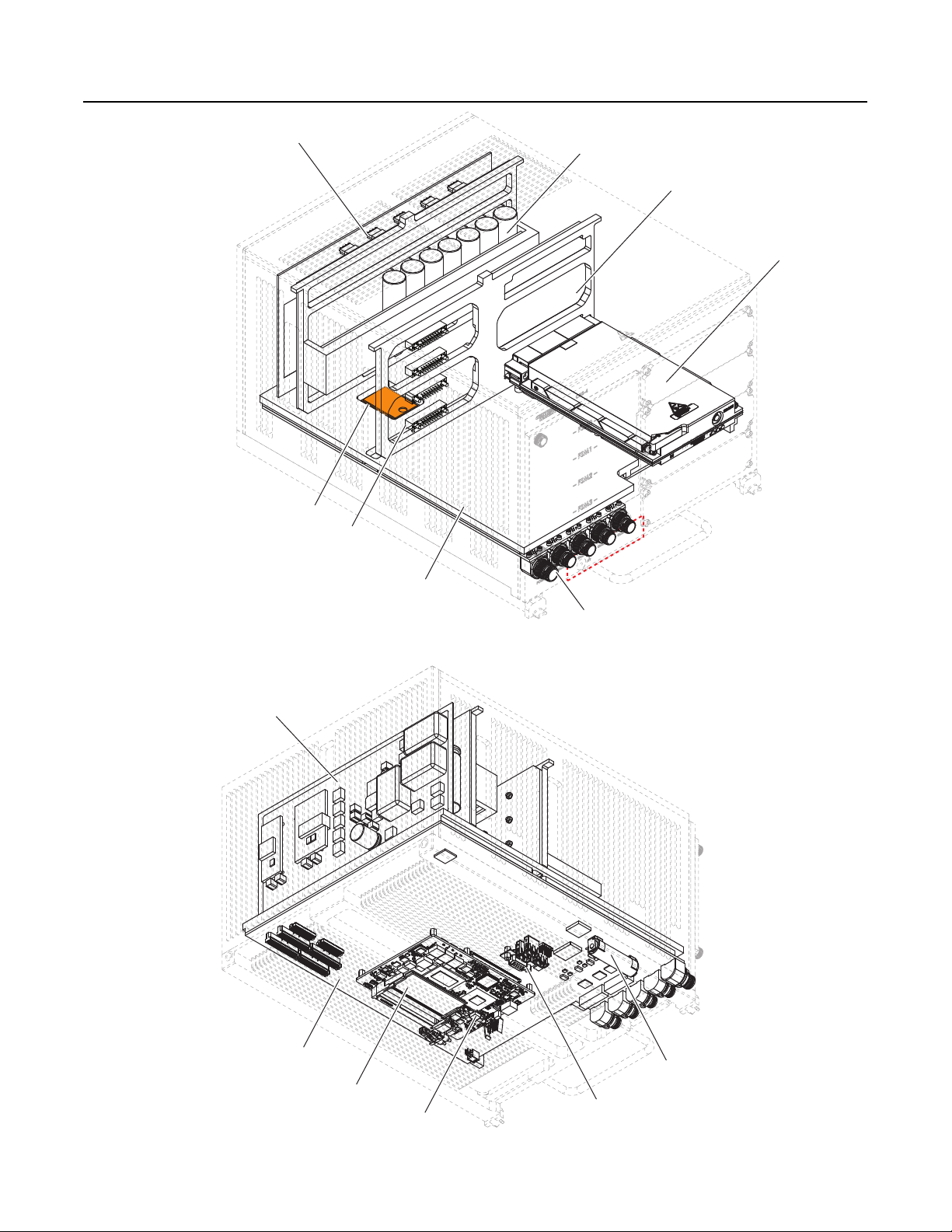
The CNS4 chassis (Figure 2.1) is made up of the following major subassemblies:
• Backplane Subassembly
• Storage Backplane
• ILE Backplane
• Holdup Subassembly
• Power Supply Subassembly
• USB Flash Module
• COM Express PCB / Memory Module
• Main Carrier Subassembly
It also contains one AA battery to supply power to the Real Time Clock (RTC) and two external
trigger monitoring circuits.
The backplane is used to provide a means of interconnecting the FSM-C modules and the ILE
module to the main carrier subassembly. The backplane is made of two joined components that
have multiple low-force insertion sockets. Both backplane components plug into the main carrier.
The main carrier subassembly provides overall system interconnection. As a result, the power
supply and hold up sub-assemblies are connected to it as well. In addition, it supports external
communications through the four Ethernet connectors and power / RS-232 connector that are
installed on it. The Ethernet connectors (GBE0 through GBE3 support 0, 100, and 1000 Base-T
Ethernet. They support Ethernet IEEE 802.3ab standard over copper in full duplex.Refer to
Cables / Connectors section for additional information regarding the interface connectors and
associated cables. The subassembly also has a set of utility connectors used for manufacturing
and service activities. Contact Curtiss-Wright for more information about end-user utilization of
these connectors.
The COM Express PCB contains the main CPU and RAM memory for the unit. The USB flash
module contains the BIOS and operating system.
The power supply assembly takes the 28 VDC input power, cleans and conditions it, and then
distribute it to the entire system. The holdup subassembly consists of a series of capacitors and a
power monitoring circuit. It ensures the unit can power down in an orderly fashion if the 28 VDC
input power is suddenly removed.
The chassis has four status LEDs. Refer to paragraph 3.1 CNS4 Chassis Controls / Indicators
for information regarding the LEDs.
Control of CNS4 chassis functions is established through the Command Line Interface (CLI). Refer
to Command Line Interface section for additional information regarding applicable CLI
commands. Multiple CNS4 chassis functions are monitored to ensure proper operation. Refer to
paragraph 6.2.5 Health for additional information.
CNS4 CSfC 2 - 1 Overview
Revision 1.0
Page 15
User Guide DDOC0108-000-A2
Figure 2.1 CNS4 Assembly
Power Supply Subassembly
eUSB Flash Module
Storage Backplane
Main Carrier Subassembly
Holdup Subassembly
ILE Backplane
ILE Module
Ethernet Connectors
Power Supply Subassembly
Main Carrier Subassembly
Memory Module
Power/ RS-232 Connector
Battery
Utility Connectors
COM Express Module
DDOC0108-0002
CNS4 CSfC 2 - 2 Overview
Revision 1.0
Page 16
User Guide DDOC0108-000-A2
Removal
Request
Button
Status LED
Fault LED
Power LED
SATA PORT
POWER
DDOC0108-0010
I2C Register EPROM
Temperature Sensor
Voltage Sensor
SYSTEM
MANAGEMENT
2.5 SATA
Solid State Drive
2.1.2 FSM-C Module
CAUTION
EQUIPMENT DAMAGE. Do not remove / install a FSM-C module with power applied or damage to
the FSM-C module and / or CNS4 will occur.
CAUTION
EQUIPMENT DAMAGE. Use ESD precautions when handling a FSM-C module. Failure to
properly handle FSM-C modules can result in damage.
CAUTION
EQUIPMENT DAMAGE. Ensure wedge-lock levers are in closed position when FSM-C module is
installed in CNS4 chassis. The levers are thermally conductive and must be closed to provide
proper heat dissipation for the FSM-C module. Failure to close levers will result in improper
operation / failure of the FSM-C module.
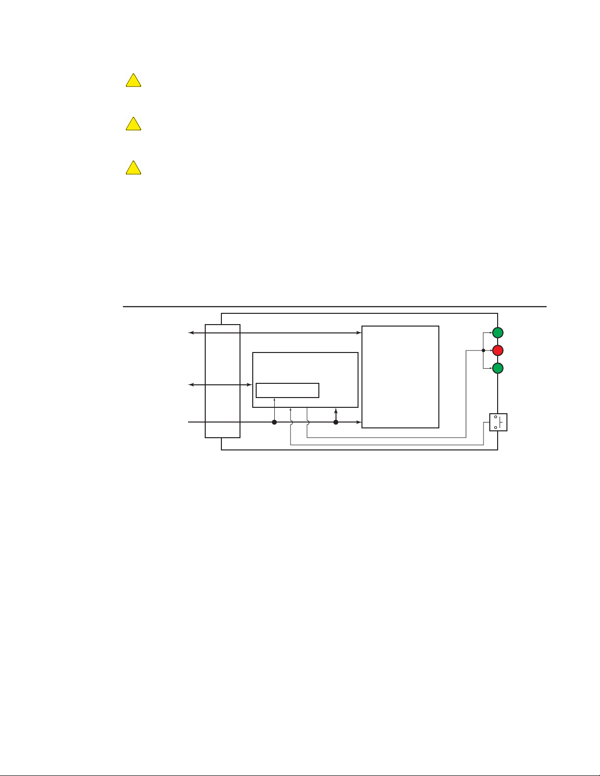
Up to four FSM-C modules can be installed in the CNS4 chassis. Each FSM-C module is a 2.0 TB
storage module that uses EMLC type memory. The FSM-C modules are installed behind an
access door located on the front of the CNS4 chassis. Each FSM-C module has three status LEDs
and a removal request button. Refer to paragraph 3.3 FSM-C Module Controls / Indicators for
information regarding the LEDs and button. Refer to Figure 2.2 for a block diagram of the FSM-C
module.
Figure 2.2 FSM-C Module Block Diagram
The FSM-C module design supports dynamic and static data wear-leveling enforcing an even
distribution of erase/write cycles. This prevents excessive writes to the same flash locations
extending the life cycle of the memory. An ECC engine is present to provide bit error detection and
correction in the physical NAND memory. In addition, a Bad Block Management (BBM) algorithm is
included to replace bad-blocks. Wear-leveling, ECC, and BBM techniques provide an extended
endurance rating for the FSM-C module storage. The FSM-C supports Serial Advanced
Technology Attachment (SATA I/II) interface bus. It is capable of data transfer rates of 1.5 Gbps
and 3.0 Gbps (SATA I and SATA II respectively).
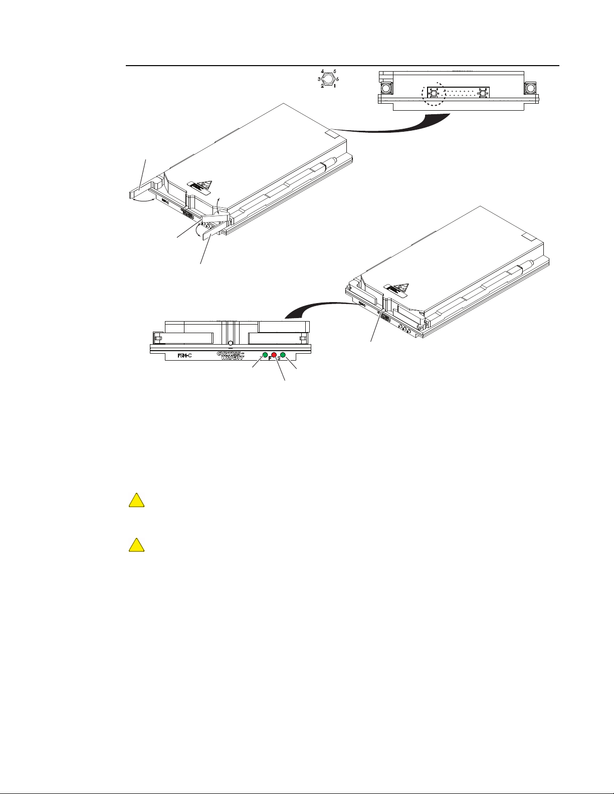
The FSM-C model (Figure 2.3) enclosure is constructed of two custom-machined anodized
aluminum covers fastened together with screws. The internal structure is designed to dissipate
component heat and provide rigidity. This closed structure makes the FSM-C module less
susceptible to problems due to adverse environments and provides silent vibration-free operation.
The FSM-C module uses conduction cooling. Its internal structure transfers heat to a physically
connected aluminum enclosure, which in turn conducts the heat through the wedgelock guide rails
to the CNS4 chassis. The interconnect plug is keyed to ensure the FSM-C module is inserted
correctly into the CNS4 chassis.
The FSM-C module is NOT hot-swappable, the CNS4 MUST be powered down prior to removal or
installation of any modules. The module is removed by grasping a pair of wedgelock levers and
pulling them away from the module's body. An additional eject lever is provided to assist with
removing the module. After removal, the FSM-C module can be transported in an ESD-safe
carrying case.
CNS4 CSfC 2 - 3 Overview
Revision 1.0
Page 17
User Guide DDOC0108-000-A2
Figure 2.3 FSM-C Module
See DETAIL A
DETAIL A
Standard Keying
Wedgelock
Lever
Eject Lever
Wedgelock
Lever
Control of FSM-C module functions is established through the Command Line Interface (CLI).
Refer to Command Line Interface section for additional information regarding applicable CLI
commands. Several FSM-C functions are monitored to ensure proper operation. Refer to
paragraph 6.2.5 Health for additional information. Refer to Ordering Information section for the
FSM-C module part number. Refer to paragraph 10.2 FSM-C Module - Install / Remove for
instruction on installing or removing the FSM-C module.
2.1.3 ILE Module
CAUTION
EQUIPMENT DAMAGE. Do not remove / install a ILE module with power applied or damage to the
ILE module and / or CNS4 will occur.
CAUTION
EQUIPMENT DAMAGE. Use ESD precautions when handling a ILE module. Failure to properly
handle ILE modules can result in damage.
The CNS4 uses the Curtiss-Wright FIPS 140-2 certifiable ILE module for hardware encryption. For
CSfC, the ILE module works in conjunction with software encryption present on each FSM-C
module. The FSM-C module(s) accepts the cipher text written from the ILE module and retains it
until read and decoded by the ILE module. The ILE module has two encryption modes:
Removal Request
DDOC0108-0009
Button
Power LED Status LED
Fault LED
• Internally generated Date Encryption Key (DEK).
• Externally provided DEK.
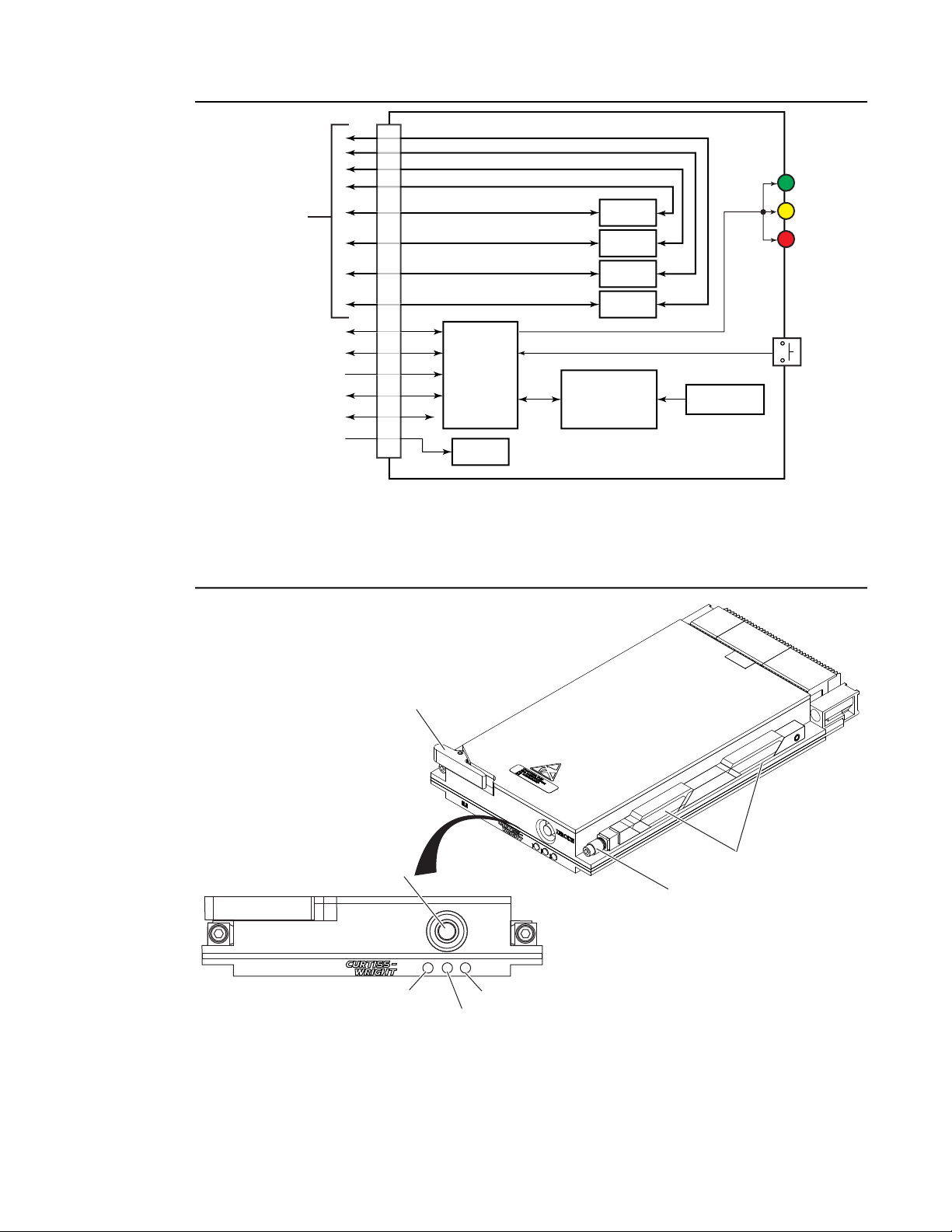
The ILE module uses the Advanced Encryption Standard (AES) and a 256-bit encryption key. As a
result, sensitive data can be protected when processed through the ILE module. Refer to Figure
2.4 for a block diagram of the ILE module.
CNS4 CSfC 2 - 4 Overview
Revision 1.0
Page 18
User Guide DDOC0108-000-A2
RS-232 (Optional)
I2C
Status
Key Purge
RS-232
(Reserve Keep Alive)
Zeroize
Button
Power LED
Key LED
Fault LED
5V
AES256-bit
Encryption
AES256-bit
Encryption
AES256-bit
Encryption
AES256-bit
Encryption
SRAM
Battery Backup
AES KEY
Storage
Admin / Use Login
Default Settings
DC-DC
Power
µController
SATA Ports
To FSM-C
Modules
DDOC0108-0014
ZEROIZE
ILE
PFS
DDOC0108-0015
Power LED Status LED
Fault LED
Eject Lever
Wedge Locks
Allen Screw
Zeroize Button
Figure 2.4 ILE Module Block Diagram
The ILE module (Figure 2.5) is NOT hot-swappable, the CNS4 MUST be powered down prior to
removal or installation of the module. The module is removed by rotating a pair of Allen screws to
lower the wedge locks. The unit is removed by grasping the eject lever and pulling the module
from the chassis. After removal, the ILE module can be transported in an ESD-safe carrying case.
Figure 2.5 ILE Module
A single ILE module contains four encryptors which performs the data encryption for all installed
CNS4 CSfC 2 - 5 Overview
FSM-C modules. The four encryptors are labeled A through D, with encryptor A assigned to FSMC module 0, B to 1, C to 2, and D to 3. As a result a single DEK can be assigned to all installed
FSM-C modules or a separate DEK can be assigned to each FSM-C module.
Revision 1.0
Page 19

User Guide DDOC0108-000-A2
The ILE module is located behind a front panel access cover labeled FIPS CRYPTO. The ILE
module has three status LEDs and a zeroize button. Refer to paragraph 3.2 ILE Module Controls
/ Indicators for information regarding the LEDs and button.
The ILE module encryption key(s) can be zeroized (removed) by one of the three methods:
• Pressing the zeroize button on the ILE.
• Applying an external trigger via a signal applied through the Power / RS-232 connector / cable.
• Sending a software command via the Command Line Interface (CLI).
Refer to paragraph 6.4.1 Zeroize for more information regarding removing the encryption key from
the CNS4 / ILE module.
NOTE
The 1st account created on the ILE is always the crypto officer account (had admin privileges).
Four additional user accounts can be created as well.
Control of ILE module functions is established through the CLI. Refer to Command Line Interface
section for additional information regarding applicable CLI commands.Several ILE functions are
monitored to ensure proper operation. Refer to paragraph 6.2.5 Healthfor additional information.
Refer to paragraph Figure 10.1 ILE Module Replacement for instruction on installing or removing
the ILE module. The ILE requires use of an account to access data. Refer to paragraph 6.4.1
Zeroizet for additional information.
2.2 CNS4 Features
• Built-In-Test
• Power-On (PBIT)
• Initiated (IBIT)
• Continuous (CBIT)
• Command Line Interface
• Encryptor Features
• CSfC Associated Encryption
• Hardware Encryption Layer
• Software Encryption Layer
• Local Zeroization
• Remote Zeroization
• Five-second Power Hold Up
• Four 1 Gigabit Ethernet Ports
• Health Monitor (with Front Panel Indicator)
• Indicator Brightness Control
• Multiple Protocols
• Common Internet File System (CIFS)
• Dynamic Host Configuration Protocol (DHCP)
• File Transfer Protocol (FTP)
• HyperText Transfer Protocol (HTTP)
• Internet Small Computer System Interface, (iSCSI)
• Network File System (NFS)
• Secure Shell Protocol (SSH)
• Simple Network Management Protocol (SNMP)
• Power / RS-232 Port
• Solid-state Storage
• Thermal Overtemp Sensors
CNS4 CSfC 2 - 6 Overview
Revision 1.0
Page 20

User Guide DDOC0108-000-A2
2.3 Protocols
The CNS4 supported protocols include CIFS, NFS, FTP, HTTP, DHCP, SNMP, and iSCSI in
addition to its RS-232 console port. These protocols are disabled by default. The unit also
supports SSH, which is always enabled. The user can enable the desired protocols to support their
application. Refer to paragraph 11.2.23 serv for additional information.
The FDEEEcPP20 and FDEAAcPP20 Protection Profiles did not consider, nor did they include
networking protocols as part of the security functional requirements, and as a result, did not
include any requirements for addressing those protocols.
Therefore, as per the FDEEEcPP20 and FDEAAcPP20, the protocols have not been examined as
part of the required assurance activities and consequently the evaluation can make no claims
about the CNS4’s networking protocols.
It is suggested that a customer using the product consider the impact of utilizing remote
administration via SSH across the network (rather than through the console) based upon their
specific use case. The customer should factor into their risk management decision the
environment in which the CNS4 operates (dedicated, segregated, private network versus residing
in a Demilitarized Zone [DMZ] accessible to the Internet), and the value of data to be protected.
2.4 CSfC Encryption
Commercial Solutions for Classified (CSfC) encryption is based on a National Security Agency
(NSA) specification. The CSfC program requires multi-layered security. Hardware data encryption
is used for the first security layer. The second security layer is software data encryption. The
hardware encryption is performed in the ILE module, the software encryption is performed on the
FSM-C module(s) loaded in the CNS4 chassis.
Proper encryption / decryption is dependent on the use of keys and passphrases. The key resides
in hardware layer on the ILE module. As a result, if an ILE module is changed, unless the exact
same key is loaded on the second module, the FSM-C modules will not be accessible. The
passphrase resides in the software layer on the FSM-C module. So if a FSM-C module is
swapped, unless the second FSM-C has been encrypted with the same passphrase, its stored
data will not be accessible.
2.4.1 Hardware Layer Encryption
CAUTION
IMPROPER OPERATION / LOST DATA. If the specific user token key is lost, the user account will
be rendered unusable.
NOTE
Refer to paragraph 6.4.2 Hardware Encryption Layer for information regarding the actual
commands and procedures used to create and log into the hardware layer.
2.4.1.1 Hardware Layer Account Creation
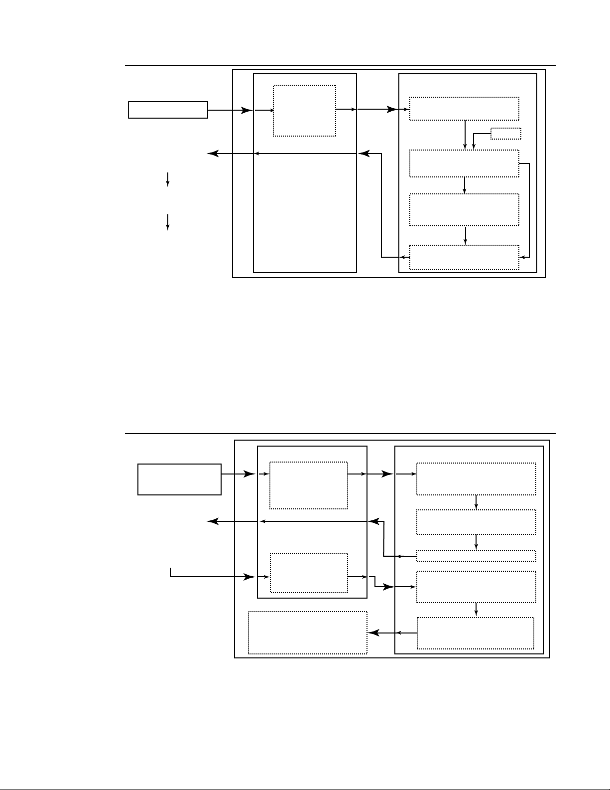
Before use, an account must be created () on the hardware layer. To start the account creation, the
user logs into the CNS4 / ILE module via the Command Line Interface (CLI). Once logged in,
additional commands are entered to create an account on the ILE hardware layer. The hardware
layer contains a Pre-Shared Key (PSK) which is generated at initial equipment power-on at the
manufacturer and provided separately by Curtiss-Wright. The PSK cannot be read out of the ILE
module.
When the account is created, a user token key is internally generated by the hardware layer. The
layer then keywraps the user token key using the PSK and supplies it to the end user through the
CLI. The keywrapped user token key is validated on a third-party system by comparing the ILEgenerated HMAC and the third party-generated HMAC. If both match, the user token is unwrapped
using the PSK. The unwrapped user token key is then used in subsequent log ins as the specificuser token.
CNS4 CSfC 2 - 7 Overview
Revision 1.0
Page 21
User Guide DDOC0108-000-A2
TERMINAL / PC
CNS4
CLI HARDWARE LAYER
(ILE MODULE)
Internally Generate
32-byte User Token Key
PSK Keywraps User Token
Key (AES256 Keywrap)
PSK
Generate HMAC (User
Token Key and PSK)
Send Encrypted User Token
Key and HMAC
Login / Create
Account on
Hardware
Crypto Layer
Validate HMAC (Use
PSK and Encrypted
User Token Key)
User Token Key is
Now a Specific-User
Token Key Tied to
Account
Decrypt User Token
Key (Use PSK )
DDOC0108-0011
Figure 2.6 Hardware Layer Account Creation
2.4.1.2 Hardware Layer Account Log In
Any subsequent use of the equipment requires logging in (Figure 2.7) to the hardware layer before
data storage and/or transfer can begin. The user enters their user name and password into the ILE
module. The hardware layer checks the information against its accounts. If the user name and
password are recognized, a random one-time 64-byte key (also referred to as a nonce) is
generated. The nonce is sent to the end-user via the CLI. The user then enters the nonce and their
specific-user token key (generated when the account was created) into a third-party HMACSHA256 generator using the user token as the key. The CLI then sends this data as a usergenerated HMAC to the hardware layer. The layer compares the user HMAC and the hardware
layer HMAC. If they are the same, the user is logged in. If they do not compare, the user is denied
access.
Figure 2.7 Hardware Layer Account Log In
CLI
TERMINAL / PC
User Generates
HMAC via 3rd-Party
Software (Use Specific
User Token Key
and Nonce)
DDOC0108-0012
If Comparison Passes,
User is Logged In
If Comparison Fails,
User is Denied Access
Log Into
Previously
Created
Account
Send
User-Generated
HMAC
CNS4
HARDWARE LAYER (ILE MODULE)
Check / Verify End-User
Name / Password
Against Account Information
Generate Random One-Time
Use 64-byte Key (Nonce)
Send Nonce
Generate HMAC (Nonce
and Specific-User
Token Key)
Compare User HMAC
and Hardware Crypto
Layer HMAC
CNS4 CSfC 2 - 8 Overview
Revision 1.0
Page 22

User Guide DDOC0108-000-A2
2.4.2 Software Layer Encryption
CAUTION
IMPROPER OPERATION / LOST DATA. If the software encryption key / passphrase is lost, the
associated FSM-C module(s) will be rendered unusable.
NOTE
Refer to paragraph 6.4.3 Software Encryption for information regarding the actual commands
and procedures used to create and log into the hardware layer.
To create the software layer encryption, the user must first log into the hardware layer. If the CNS4
/ ILE module is connected to the same terminal or PC that was used to create the hardware layer
account, the ILE module will automatically validate the account and allow access to the FSM-C (if
installed). If the CNS4 / ILE module is connected to a different terminal or PC, the user will be
required to enter the specific user token key via the CLI. After that procedure has been
accomplished, creation of the software layer encryption can begin.
Software encryption is performed after the FSM-C module is formatted and mounted. Multiple
modules can be encrypted using the same or different encryption key / passphrase. In addition,
FSM-C can be partitioned and have each partition use the same or different encryption key /
passphrase. Before attempting to encrypt the FSM-C module, its status should be checked. If the
status is not correct, creation of the software encryption layer will fail.
Subsequent use of the FSM-C module is dependent upon the proper encryption key / passphrase
being entered using the Command Line Interface (CLI). Failure to enter the proper information will
result in the FSM-C module being inaccessible for data storage or use.
CNS4 CSfC 2 - 9 Overview
Revision 1.0
Page 23
User Guide DDOC0108-000-A2
Controls and Indicators
3.1 CNS4 Chassis Controls / Indicators
NOTE
Refer to paragraph 3.1.1 Chassis LED Brightness for information regarding how to set chassis
LED illumination levels.
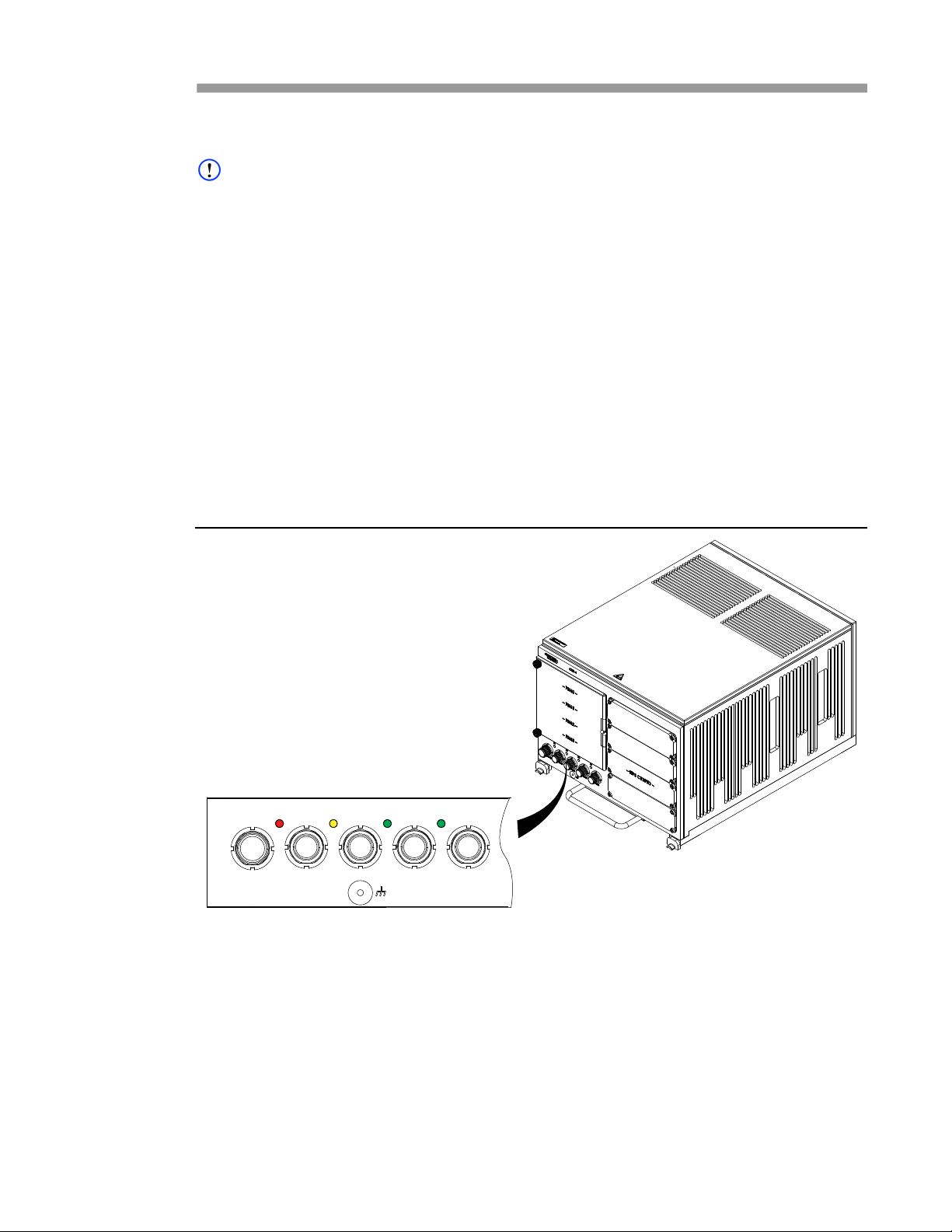
The CNS4 chassis (Figure 3.1) has four LED status indicators on the bottom of the front panel: S0,
S1, S2, and S3. During normal operation, S1, S2, and S3 will be ON; S0 will be off. The
illumination level of the LEDs is user programmable from 0 (off) to 100%. The function of these
indicators is as follows.
• S0 (RED). This LED is the health alert indicator. It turns ON when any monitored parameter is
outside of specified tolerance. It turns OFF when the parameter returns to normal. It also turns
on when:
• Internal communications cease for a period of 40 seconds.
• Shutdown command is issued.
• S1 (YELLOW). This LED turns ON whenever 28VDC is applied to the CNS4 power supply.
• S2 (GREEN). This LED turns ON after the CNS4 has booted up and is ready for operation.
• S3 (GREEN). This LED turns ON when the storage function (via the FSM-C modules) is ready
for read/writer operations.
There are no controls associated with CNS4 chassis.
Figure 3.1 CNS4 Chassis Indicators
S0 S1 S2 S3
DDOC0108-0026
POWER GBE2GBE0 GBE1 GBE3
3.1.1 Chassis LED Brightness
The brightness of the chassis LEDs can be independently set from 0 to 100% brightness. This
accomplished by changing the duty cycle of the power applied to the individual LEDs. The
command line interface (CLI) ledcntrl command is used in association with -s option to select the
individual LED and -d option to select its duty cycle. See paragraph 11.2.18 ledctrl for detailed
information.
3.2 ILE Module Controls / Indicators
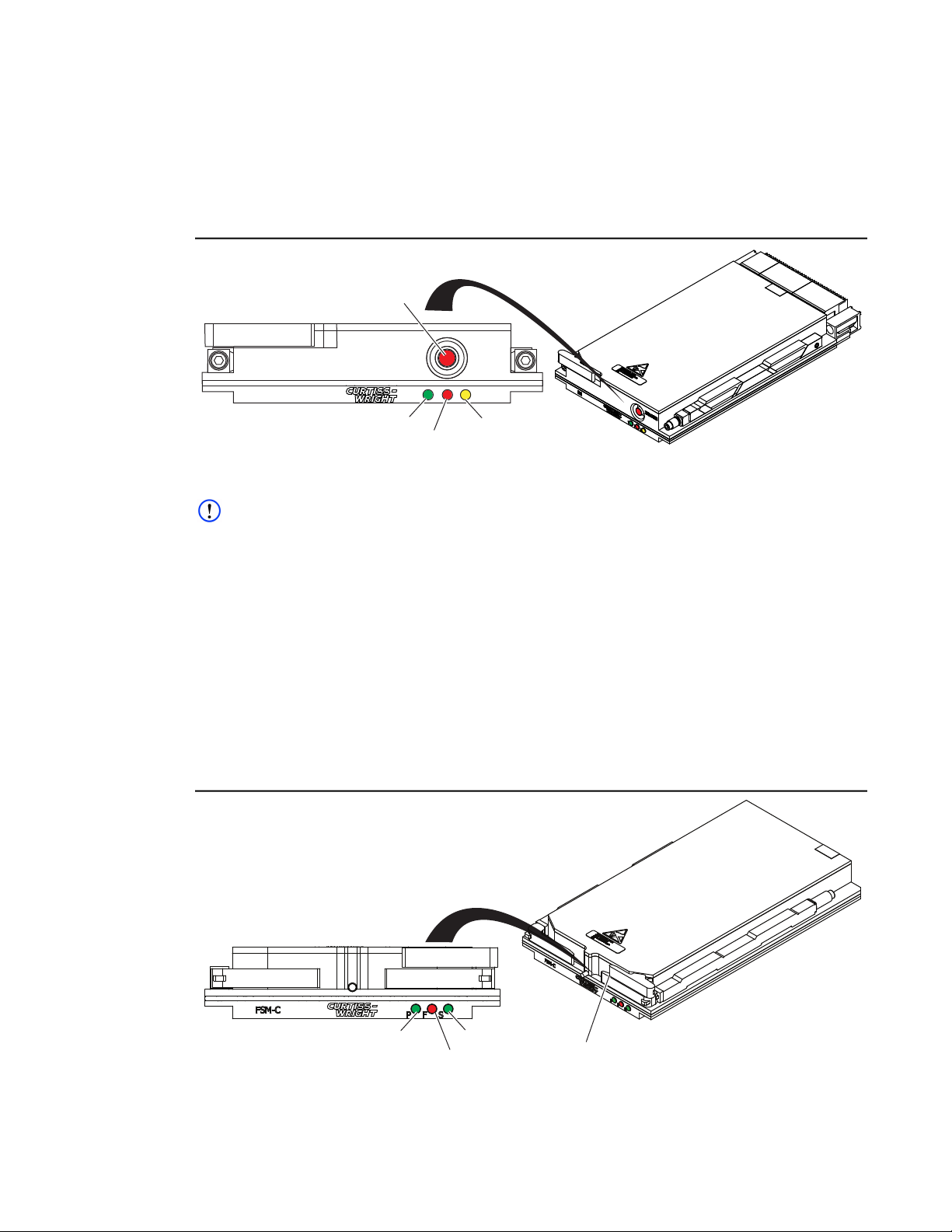
The ILE module (Figure 3.2) has three LED status indicators: P, F, and S. During normal operation,
P and S will be ON; F will be off. The illumination level of the LEDs is preset and non-adjustable.
CNS4 CSfC 3 - 1 Controls and Indicators
Revision 0.0
Page 24
User Guide DDOC0108-000-A2
ZEROIZE
ILE
PFS
DDOC0108-0028
Power LED Status LED
Fault LED
Zeroize Button
The function of the ILE module indicators is as follows.
• P (GREEN). This LED turns ON whenever 28VDC is applied to the ILE module.
• F (RED). This LED turns ON whenever the ILE module has a fault condition.
• S (YELLOW). This LED turns ON whenever the encryption key(s) are loaded into the ILE
module.
The ZEROIZE button is used to zeroize (delete) the encryption keys loaded in the ILE module.
Figure 3.2 ILE Module Controls / Indicators
3.3 FSM-C Module Controls / Indicators
NOTE
The F (RED) LED turns on until after the CNS4 has booted up, started communicating, and loaded
encryption keys into the FSM-C module.
The FSM-C module (Figure 3.3) has three LED status indicators: P, F, and S. During normal
operation, P and S will be ON; F will be off. The illumination level of the LEDs is preset and nonadjustable. The function of these indicators is as follows.
• P (GREEN). This LED turns ON when 28VDC is applied and FSM-C module initialization has
occurred.
• F (RED). This LED turns ON whenever there is a Built-In Test (BIT) failure or operational
problem related to the FSM-C module. If the problem is also related to the CNS4, the S0 will
turn ON.
• S (GREEN). This LED turns ON whenever the FSM-C module is active (reading / writing data).
The REMOVAL REQUEST button is disabled in this configuration.
Figure 3.3 FSM-C Module Controls / Indicators
DDOC0108-0027
Power LED Status LED
Fault LED
CNS4 CSfC 3 - 2 Controls and Indicators
Removal Request
Button
Revision 0.0
Page 25
User Guide DDOC0108-000-A2
DDOC0108-0017
F
P
S
FSM-C Module
ILE Module
Tamper-Proof
Seal Locations
Installation
4.1 Package
The CNS4 package contents are listed below:
• CNS4 Chassis
• ILE Module
• Product Documentation CD
Optional Items. Refer to Ordering Information section for PN information. Refer to paragraph 1.6
Ordering Process for information on how to order the item(s).
• FSM-C Modules
• Power / RS-232 Lab Cable
• Ethernet Lab Cables
• ATR Tray / Shock Mounts
4.2 Inspection
The CNS4 is a multi-part data storage system that consists of a CNS4 chassis, up to four FSM-C
modules and an ILE module. Additional accessories may be included (if ordered). All received
items should be inspected for damage. Inspect all units as follows:
• All screws should be tight.
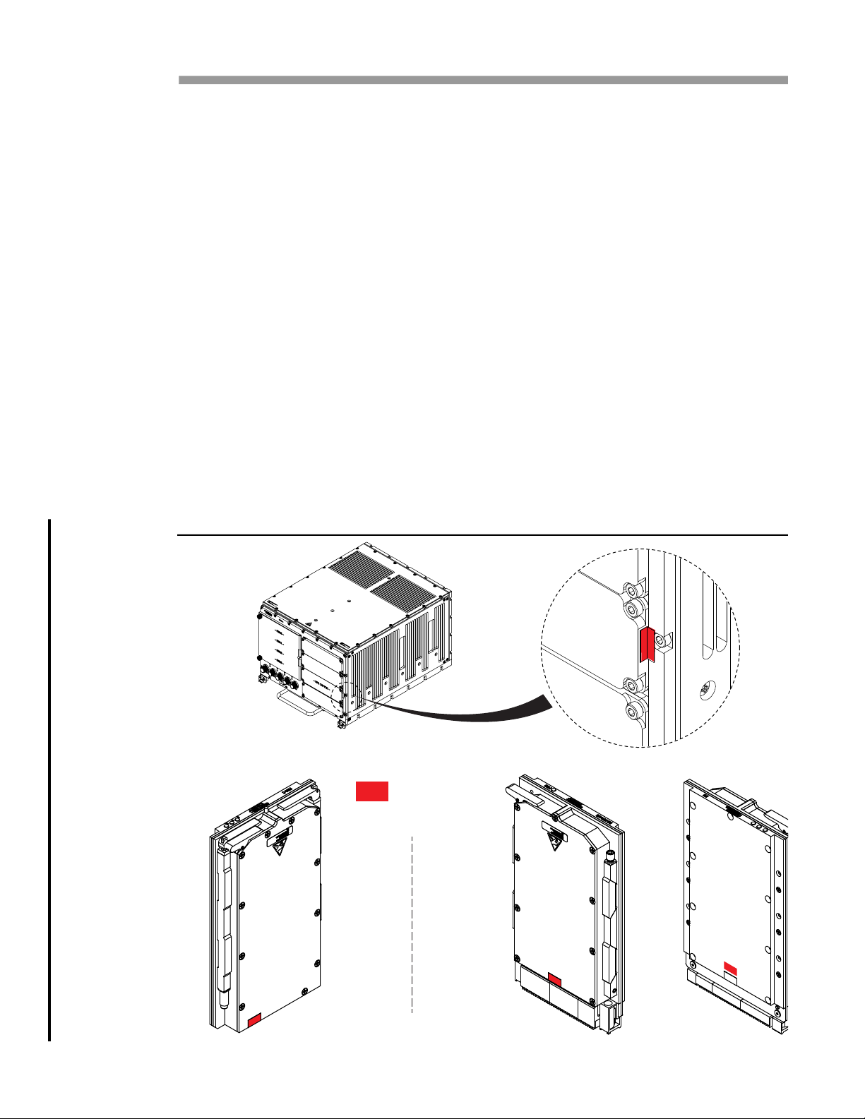
• All anti-tamper labels (Figure 4.1) should be unbroken.
• All components should be free from any dents, cracks, or damage.
• All connectors pins should be present, straight, and undamaged.
Figure 4.1 Anti-Tamper Label Locations
CNS4 CSfC 4 - 1 Installation
Revision 1.0
Page 26
User Guide DDOC0108-000-A2
DDOC0108-0018
150°
6.75 In.
(171.4 mm)
If either the CNS4 chassis or associated modules were damaged in shipping or the enclosure was
breached, immediately notify Curtiss-Wright Defense Solutions or your supplier.
4.3 Mounting
Mounting environment considerations should include operating temperature limits, humidity, and
vibration limits. Other considerations should include clearance for mounting hardware, cables, and
safe installation or removal of the CNS4 from its mounting structure. Precautions should be taken
when cables are routed around structures that could cause excessive abrasion, such as around
the corner of vibrating equipment.
Installation of the CNS4 can put an increased demand on cooling systems by raising ambient air
temperatures. Evaluate changes in airflow obstructions and temperatures around equipment and
possible detrimental surface temperatures due to conducted heat. See Appendix A for thermal
limit specifications.
If installation and / or removal of FSM-C modules is desired while the CNS4 remains mounted, be
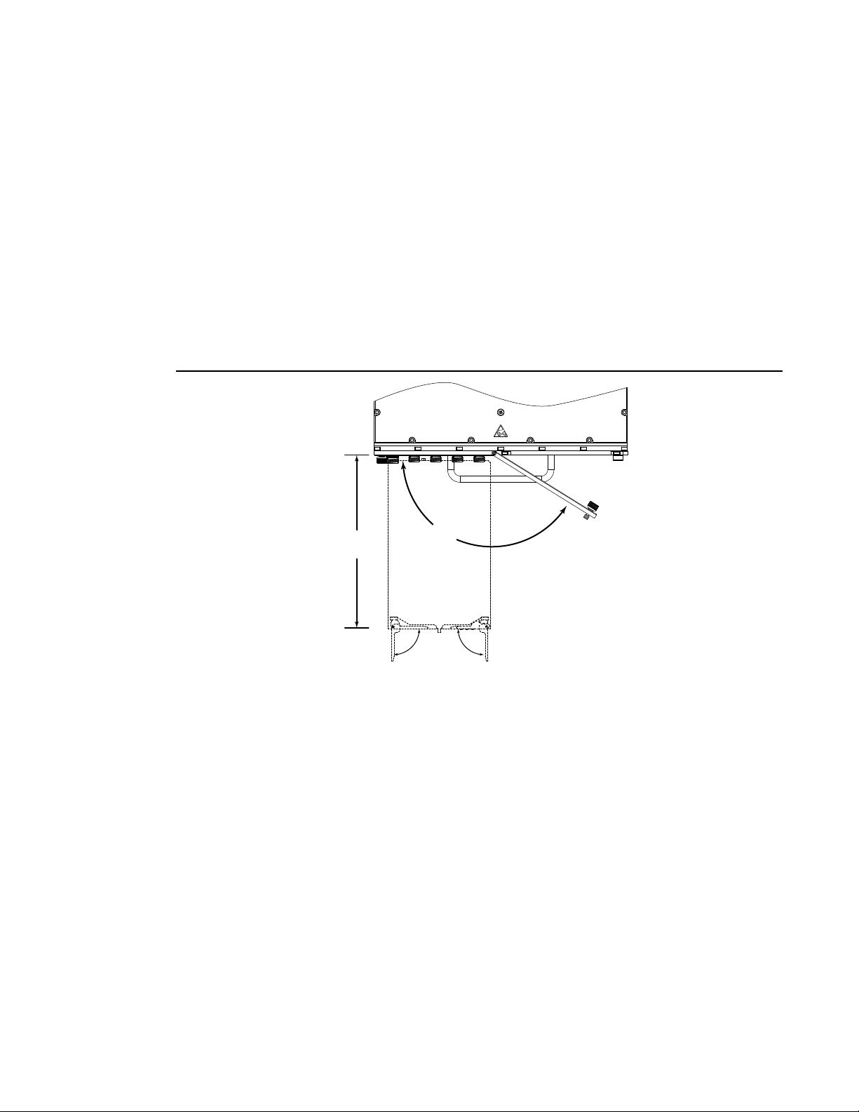
sure to allow clearance (4.4) for the door to open and the FSM-C module(s) to be positioned in
front of the CNS4.
Figure 4.2 Required Door Clearance
4.3.1 Mounting - User Defined
The CNS4 can be mounted directly to a mounting surface. The unit provides holes in the rear for
interfacing with mounting pins. The front provides J-hooks to secure the unit in place. Refer to
Specifications section, Figure A.1 for dimensional information.
4.3.2 Mounting - ARINC Tray
Mechanical mounting of the CNS4 can be accomplished using a ARINC 404 1 ATR short tray. The
tray has the mounting components in place and offers options for use of shock isolators. Contact
Curtiss-Wright Defense Solutions for information on the ARINC tray.
4.4 CNS4 Install / Remove
4.4.1 Install (User Defined Mount)
1. Slide CNS4 back so mounting pins engage chassis holes.
2. Pivot mounting knobs up so they capture J-hooks.
3. Rotate mounting knobs to secure CNS4 to mounting surface.
CNS4 CSfC 4 - 2 Installation
4. Connect Ethernet cables to front panel connectors GBE0 through GBE3.
5. Connect power / RS-232 cable to front panel power connector.
Revision 1.0
Page 27
User Guide DDOC0108-000-A2
4.4.2 Install (ARINC Tray)
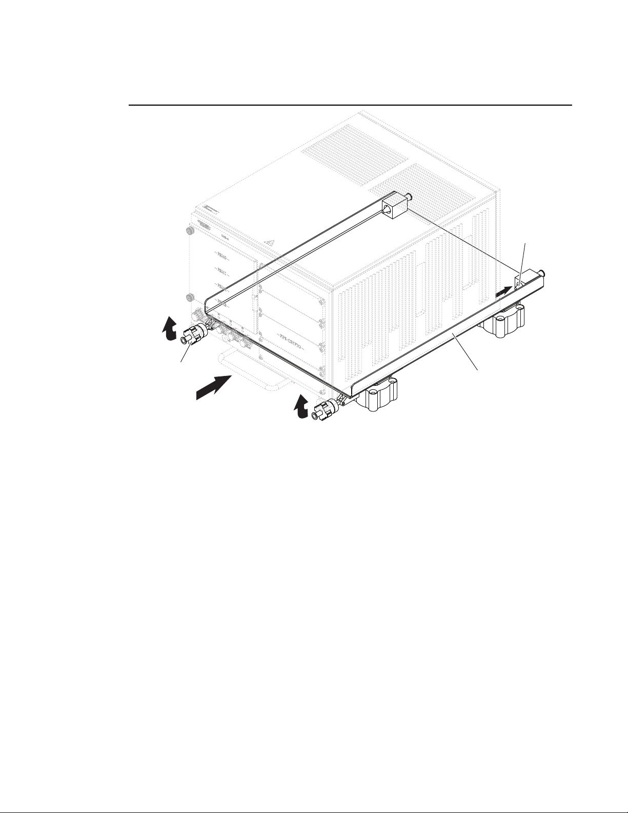
1. Place CNS4 (Figure 4.3) on ARINC tray.
Figure 4.3 CNS4 Mounting - ARINC Tray
Mounting Pin
Mounting Knob
2. Slide CNS4 back so mounting pins engage chassis holes.
3. Pivot mounting knobs up so they capture J-hooks.
4. Rotate mounting knobs (Figure 4.4) to secureCNS4 to tray.
5. Connect Ethernet cables to front panel connectors GBE0 through GBE3.
6. Connect power / RS-232 cable to front panel power connector.
4.4.3 Remove (User Defined Mount)
1. If applicable, turn 28VDC power supply OFF.
2. Disconnect power / RS-232 cable from front panel power connector.
3. Disconnect Ethernet cables from front panel connectors GBE0 through GBE3.
4. Rotate mounting knobs to release CNS4 from mounting surface.
5. Pivot mounting knobs down / away from J-hooks.
6. Slide CNS4 forward so mounting pins disengage chassis holes.
7. Remove CNS4 from mounting surface
4.4.4 Remove (ARINC Tray)
Tray
DDOC0108-0006
1. If applicable, turn 28VDC power supply OFF.
2. Disconnect power / RS-232 cable from front panel power connector.
3. Disconnect Ethernet cables from front panel connectors GBE0 through GBE3.
4. Rotate mounting knobs to release CNS4 from ARINC tray.
CNS4 CSfC 4 - 3 Installation
Revision 1.0
Page 28
User Guide DDOC0108-000-A2
DDOC0108-0021
Power / RS-232
Connector
Ethernet
Connectors
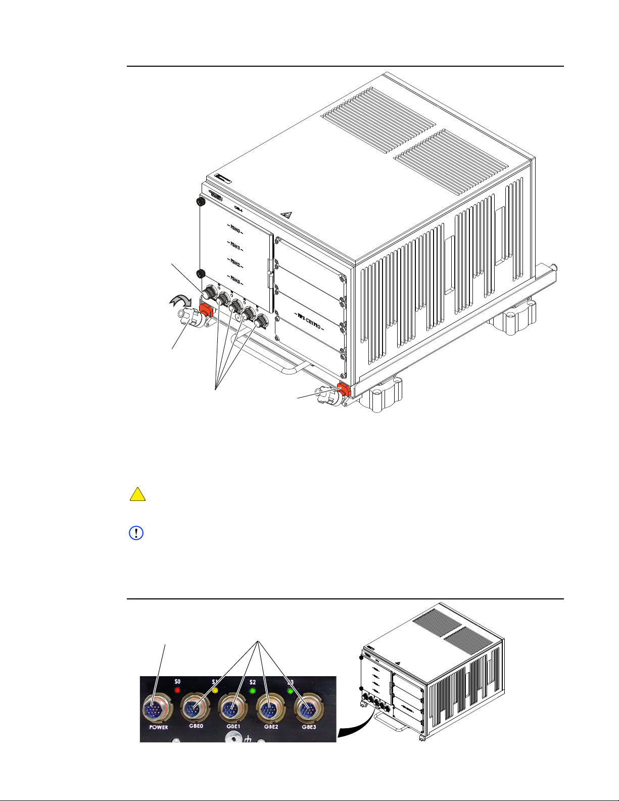
Figure 4.4 CNS4 Installed on ARINC Tray
Power / RS-232
Connector
Mounting
Knob
5. Pivot mounting knobs down / away from J-hooks (Figure 3-4).
6. Slide CNS4 forward so mounting pins disengage chassis holes.
7. Remove CNS4 from ARINC tray
4.5 Cables
CAUTION
Make sure the 28VDC power supply is OFF when connecting the power / RS-232 cable to the unit
or damage may occur.
NOTE
The CNS4 typically does not have an Ethernet cable attached to GBE3.
All connections to the CS4 are on the front panel (Figure 4.5). Be sure the external 28VDC power
supply is off when making connections.
Figure 4.5 CNS4 Connectors
Ethernet
Connectors
J-Hook
DDOC0108-0007
CNS4 CSfC 4 - 4 Installation
Revision 1.0
Page 29
User Guide DDOC0108-000-A2
DDOC0108-0020
RS-232 Connector
Power / RE-232
Connector
28 VDC (+)
28 VDC
RTN (-)
DDOC0108-0019
RJ-45 Port
Ethernet
Connector
4.5.1 Power / RS-232 Cable
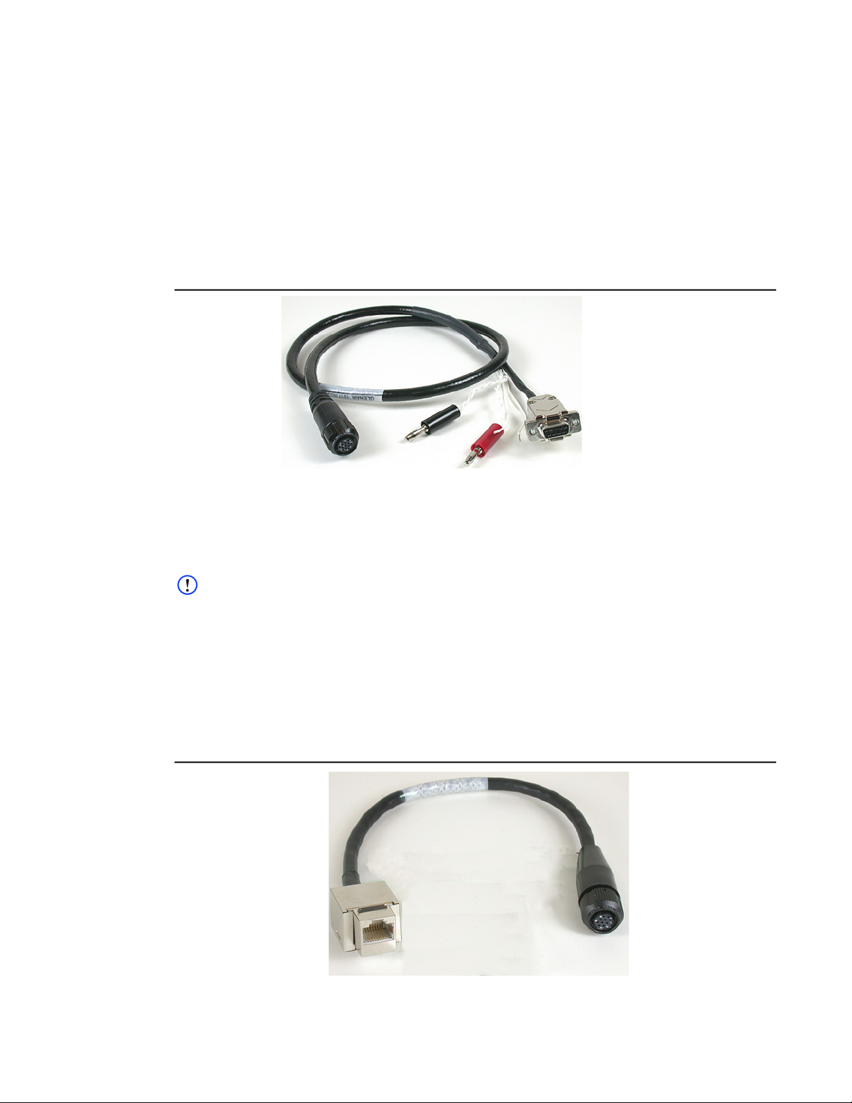
The CNS4 Power / RS-232 Lab Cable (Figure 4.6) is used to make power and serial data
connections to the CNS4. The CNS4 requires an input power of +28 volts and ground. The serial
data portion of the cable is used to interface the Command Line Interface (CLI) terminal to the unit.
Refer to paragraph B.1 Power / RS-232 for connector pin signal information.
Connections:
• The 13-pin connector (P1) mates to CNS4 power connector.
• The red plug connects to 28 VDC.
• The black plug connects to 28 VDC return.
• The RS-232 connector connects to the terminal RS-232 port.
Figure 4.6 Power / RS-232 Lab Cable
4.5.2 Ethernet Cable
The Ethernet lab cables (Figure 4.7) are used to make network connections to the CNS4. Refer to
paragraph B.2 Ethernet for connector pin signal information. Each Ethernet connector is keyed to
the respective CNS4 connector.
NOTE
The CNS4 typically does not have an Ethernet cable attached to GBE3.
• GBE0 Ethernet Lab Cable (12-Inch Long) 801-008-16NF7-10SA
• GBE1 Ethernet Lab Cable (12-Inch Long) 801-008-16NF7-10SB
• GBE2 Ethernet Lab Cable (12-Inch Long) 801-008-16NF7-10SC
Connections
• The 10-pin connector (P1) mates to CNS4 GBE0 through GBE2.
• The RJ-45 port (P2) accepts a normal Ethernet cable RJ-45 plug.
Figure 4.7 Ethernet Lab Cable
CNS4 CSfC 4 - 5 Installation
Revision 1.0
Page 30

User Guide DDOC0108-000-A2
Quick Start
The quick start section provides easy to access commands and examples.
5.1 Connections and Controls
1. Refer to paragraph 6.1 Lab Setup / Connections for connection information.
2. Refer to Controls and Indicators section for information about indicators and controls.
5.2 Communications Setup
Refer to paragraph 6.2.2 Communications for information.
5.3 Login
To access the FSMs, the user must be logged into CNS4 and hardware encryption layer. However,
once the software encryption layer has been activated, the user must be logged into the software
layer as well.
5.3.1 CNS4
NOTE
The administrator can configure the unit using the Command Line Interface (CLI).
Administrator
• Username: admin
• Password: istrator
NOTE
The user can access the drives configured as network storage. The user cannot access the CLI.
User
• Username: user
• Password: password
5.4 Hardware Layer
Refer to paragraph 6.4.2 Hardware Encryption Layer for information.
NOTE
The unit is shipped with a default ILE account
• Username: user
• Password: Password1
5.5 Software Layer
Refer to paragraph 6.4.3 Software Encryption for information.
5.6 Partition Disks
5.6.1 Erase All Partitions / All Slots
Commands:
sysconfig –e
sysconfig --wipe
5.6.2 Check Drive Status
Command:
sysconfig
Example:
cns> sysconfig
sysconfig]
DiskConfig
CNS4 CSfC 5 - 1 Quick Start
Revision 1.0
Page 31

User Guide DDOC0108-000-A2
Unconfigured_disks: numDisk=4
Disk0: name=fsm0-d0 size=2000GB
Disk1: name=fsm1-d0 size=2000GB
Disk2: name=fsm2-d0 size=2000GB
Disk3: name=fsm3-d0 size=2000GB
Raid_disks: numDisk=0
Raid_volumes: numDisk=0
Partitions: numPartitions=0
--- Device Partitions --[!sysconfig] OK
Check Software Encryption (SWE) Status:
swcrypt
Example:
cns> swcrypt
[swcrypt]
Partitions: 0
[!swcrypt] OK
5.6.3 Create Single Partition on FSM0
Command:
sysconfig --part fsm0-d0 1 100% -w
Example:
cns> sysconfig --part fsm0-d0 1 100% -w
[sysconfig]
Partition_disk: status=OK
[!sysconfig] OK
Check Status:
cns> sysconfig
[sysconfig]
DiskConfig:
Unconfigured_disks: numDisk=3
Disk0: name=fsm1-d0 size=2000GB
Disk1: name=fsm2-d0 size=2000GB
Disk2: name=fsm3-d0 size=2000GB
Individual_disks: numDisk=1
Disk0: name=fsm0-d0 size=2000GB
Raid_disks: numDisk=0
Raid_volumes: numDisk=0
Partitions: numPartitions=1
Part0: name=fsm0-d0 size=2000246MB pSize=100.00% dp=1 numServ=1
sName=Unconfigured swe=no
--- Device Partitions --[!sysconfig] OK
Check SWE Status:
cns> swcrypt
[swcrypt]
Partitions: 1
Part0: name=fsm0-d01 swe=no
[!swcrypt] OK
5.6.4 Create Single Partition on FSM1
Command:
sysconfig --part fsm1-d0 1 100% -w
Example:
cns> sysconfig --part fsm0-d0 1 100% -w
[sysconfig]
Partition_disk: status=OK
[!sysconfig] OK
CNS4 CSfC 5 - 2 Quick Start
Revision 1.0
Page 32

User Guide DDOC0108-000-A2
Check Status:
cns> sysconfig
[sysconfig]
DiskConfig:
Unconfigured_disks: numDisk=2
Disk0: name=fsm2-d0 size=2000GB
Disk1: name=fsm3-d0 size=2000GB
Individual_disks: numDisk=2
Disk0: name=fsm0-d0 size=2000GB
Disk1: name=fsm1-d0 size=2000GB
Raid_disks: numDisk=0
Raid_volumes: numDisk=0
Partitions: numPartitions=2
Part0: name=fsm0-d0 size=2000246MB pSize=100.00% dp=1 numServ=1
sName=Unconfigured swe=no
Part1: name=fsm1-d0 size=2000246MB pSize=100.00% dp=1 numServ=1
sName=Unconfigured swe=no
-- Device Partitions --[!sysconfig] OK
Check SWE Status:
cns> swcrypt
[swcrypt]
Partitions: 2
Part0: name=fsm0-d01 swe=no
Part1: name=fsm1-d01 swe=no
[!swcrypt] OK
5.6.5 Create Single Partition on FSM2
Command:
sysconfig --part fsm2-d0 1 100% -w
Example:
cns> sysconfig --part fsm2-d0 1 100% -w
[sysconfig]
Partition_disk: status=OK
[!sysconfig] OK
Check Status:
cns> sysconfig
[sysconfig]
DiskConfig:
Unconfigured_disks: numDisk=1
Disk0: name=fsm3-d0 size=2000GB
Individual_disks: numDisk=3
Disk0: name=fsm0-d0 size=2000GB
Disk1: name=fsm1-d0 size=2000GB
Disk2: name=fsm2-d0 size=2000GB
Raid_disks: numDisk=0
Raid_volumes: numDisk=0
Partitions: numPartitions=3
Part0: name=fsm0-d0 size=2000246MB pSize=100.00% dp=1 numServ=1
sName=Unconfigured swe=no
Part1: name=fsm1-d0 size=2000246MB pSize=100.00% dp=1 numServ=1
sName=Unconfigured swe=no
Part2: name=fsm2-d0 size=2000246MB pSize=100.00% dp=1 numServ=1
sName=Unconfigured swe=no
-- Device Partitions --[!sysconfig] OK
CNS4 CSfC 5 - 3 Quick Start
Revision 1.0
Page 33

User Guide DDOC0108-000-A2
Check SWE Status:
cns> swcrypt
[swcrypt]
Partitions: 3
Part0: name=fsm0-d01 swe=no
Part1: name=fsm1-d01 swe=no
Part2: name=fsm2-d01 swe=no
[!swcrypt] OK
5.6.6 Create Single Partition on FSM3
Command:
sysconfig --part fsm3-d0 1 100% -w
Example:
cns> sysconfig --part fsm3-d0 1 100% -w
[sysconfig]
Partition_disk: status=OK
[!sysconfig] OK
Check Status:
cns> sysconfig
[sysconfig]
DiskConfig:
Individual_disks: numDisk=4
Disk0: name=fsm0-d0 size=2000GB
Disk1: name=fsm1-d0 size=2000GB
Disk2: name=fsm2-d0 size=2000GB
Disk3: name=fsm4-d0 size=2000GB
Raid_disks: numDisk=0
Raid_volumes: numDisk=0
Partitions: numPartitions=3
Part0: name=fsm0-d0 size=2000246MB pSize=100.00% dp=1 numServ=1
sName=Unconfigured swe=no
Part1: name=fsm1-d0 size=2000246MB pSize=100.00% dp=1 numServ=1
sName=Unconfigured swe=no
Part2: name=fsm2-d0 size=2000246MB pSize=100.00% dp=1 numServ=1
sName=Unconfigured swe=no
Part3: name=fsm3-d0 size=2000246MB pSize=100.00% dp=1 numServ=1
sName=Unconfigured swe=no
-- Device Partitions --[!sysconfig] OK
Check SWE Status:
cns> swcrypt
[swcrypt]
Partitions: 4
Part0: name=fsm0-d01 swe=no
Part1: name=fsm1-d01 swe=no
Part2: name=fsm2-d01 swe=no
Part3: name=fsm2-d01 swe=no
[!swcrypt] OK
5.6.7 Create NAS Partitions on FSM0 - 3
NOTE
The first # in the command is the # partitions to assign as NAS drives. The subsequent #s are the
partitions #'s, in a list…
Command:
sysconfig --nas 4 0 1 2 3
CNS4 CSfC 5 - 4 Quick Start
Revision 1.0
Page 34

User Guide DDOC0108-000-A2
Example:
cns> sysconfig --nas 4 0 1 2 3
[sysconfig]
DiskConfig:
Individual_disks: numDisk=4
Disk0: name=fsm0-d0 size=2000GB
Disk1: name=fsm1-d0 size=2000GB
Disk2: name=fsm2-d0 size=2000GB
Disk3: name=fsm3-d0 size=2000GB
Raid_disks: numDisk=0
Raid_volumes: numDisk=0
Partitions: numPartitions=4
Part0: name=fsm0-d0 size=2000246MB pSize=100.00% dp=1 numServ=1 sName=fsm_nas0
fmt=no mnt=0 enb=0 swe=no
Part1: name=fsm1-d0 size=2000246MB pSize=100.00% dp=1 numServ=1 sName=fsm_nas1
fmt=no mnt=0 enb=0 swe=no
Part2: name=fsm2-d0 size=2000246MB pSize=100.00% dp=1 numServ=1 sName=fsm_nas2
fmt=no mnt=0 enb=0 swe=no
Part3: name=fsm3-d0 size=2000246MB pSize=100.00% dp=1 numServ=1 sName=fsm_nas3
fmt=no mnt=0 enb=0 swe=no
--- Device Partitions --NAS on partition 0 1 2 3
[!sysconfig] OK
Check SWE Status:
cns> swcrypt
[swcrypt]
Partitions: 4
Part0: name=fsm0-d01 swe=no
Part1: name=fsm1-d01 swe=no
Part2: name=fsm2-d01 swe=no
Part3: name=fsm3-d01 swe=no
[!swcrypt] OK
5.7 Create Software Encryption Containers on FSM2 and FSM3
Create Passphrase (Linux)
echo Cns4:istratorFsm3 > keyfile3.txt
scp keyfile3.txt [email protected]:/keyfiles
Create Passphrase (Windows)
1. Create a passphrase for FSM2 as follows:
a. Use a text editor to create file containing “Cns4:istratorFsm2”.
b. Save file on PC as keyfile2.txt.
2. Create a passphrase for FSM3 as follows:
a. Use a text editor to create file containing “Cns4:istratorFsm3”.
b. Save file on PC as keyfile3.txt.
3. On a PC with Linux OS, type scp keyfile2.txt [email protected]:/keyfiles/ to
move keyfile3 to CNS4 keyfile director.
4. On a PC with Linux OS, type scp keyfile3.txt [email protected]:/keyfiles/ to
move keyfile3 to CNS4 keyfile director.
Create Containers
FSM2
cns> swcrypt --init 2 --key-file /keyfiles/keyfile2.txt
[swcrypt]
cmd=init Part=2 status=OK
[!swcrypt] OK
CNS4 CSfC 5 - 5 Quick Start
Revision 1.0
Page 35

User Guide DDOC0108-000-A2
FSM3
cns> swcrypt --init 3 --key-file /keyfiles/keyfile3.txt
[swcrypt]
cmd=init Part=3 status=OK
[!swcrypt] OK
Check Status:
cns> sysconfig
[sysconfig]
DiskConfig:
Individual_disks: numDisk=4
Disk0: name=fsm0-d0 size=2000GB
Disk1: name=fsm1-d0 size=2000GB
Disk2: name=fsm2-d0 size=2000GB
Disk3: name=fsm3-d0 size=2000GB
Raid_disks: numDisk=0
Raid_volumes: numDisk=0
Partitions: numPartitions=4
Part0: name=fsm0-d0 size=2000246MB pSize=100.00% dp=1 numServ=1
sName=fsm_nas0 fmt=no mnt=0 enb=0 swe=no
Part1: name=fsm1-d0 size=2000246MB pSize=100.00% dp=1 numServ=1
sName=fsm_nas1 fmt=no mnt=0 enb=0 swe=no
Part2: name=fsm2-d0 size=2000246MB pSize=100.00% dp=1 numServ=1
sName=fsm_nas2 fmt=na mnt=0 enb=0 swe=closed
Part3: name=fsm3-d0 size=2000246MB pSize=100.00% dp=1 numServ=1
sName=fsm_nas3 fmt=na mnt=0 enb=0 swe=closed
--- Device Partitions --NAS on partition 0 1 2 3
Check SWE Status:
cns> swcrypt
[swcrypt]
Partitions: 4
Part0: name=fsm0-d01 swe=no
Part1: name=fsm1-d01 swe=no
Part2: name=fsm2-d01 swe=closed
Part3: name=fsm3-d01 swe=closed
[!swcrypt] OK
5.8 Open Software Encryption Containers on FSM2 and FSM3
5.8.0.1 Method 1
1. Open FSM2 as follows:
NOTE
Enter password 'Cns4:PasswordFsm2' when prompted.
Command
swcrypt --open 2 --pass
Example
cns> swcrypt --open 2 --pass
[swcrypt]
cmd=open Part=2 Enter passphrase for /dev/sdb1:
Verify passphrase:
status=OK
[!swcrypt] OK
Check Status
cns> sysconfig
[sysconfig]
DiskConfig:
Individual_disks: numDisk=4
Disk0: name=fsm0-d0 size=2000GB
CNS4 CSfC 5 - 6 Quick Start
Revision 1.0
Page 36

User Guide DDOC0108-000-A2
Disk1: name=fsm1-d0 size=2000GB
Disk2: name=fsm2-d0 size=2000GB
Disk3: name=fsm3-d0 size=2000GB
Raid_disks: numDisk=0
Raid_volumes: numDisk=0
Partitions: numPartitions=4
Part0: name=fsm0-d0 size=2000246MB pSize=100.00% dp=1 numServ=1
sName=fsm_nas0 fmt=no mnt=0 enb=0 swe=no
Part1: name=fsm1-d0 size=2000244MB pSize=100.00% dp=1 numServ=1
sName=fsm_nas1 fmt=no mnt=0 enb=0 swe=no
Part2: name=fsm2-d0 size=2000244MB pSize=100.00% dp=1 numServ=1
sName=fsm_nas2 fmt=no mnt=0 enb=0 swe=open
Part3: name=fsm3-d0 size=2000246MB pSize=100.00% dp=1 numServ=1
sName=fsm_nas3 fmt=na mnt=0 enb=0 swe=closed
--- Device Partitions --NAS on partition 0 1 2 3
[!sysconfig] OK
Check SWE Status:
cns> swcrypt
[swcrypt]
Partitions: 4
Part0: name=fsm0-d01 swe=no
Part1: name=fsm1-d01 swe=no
Part2: name=fsm2-d01 swe=open
Part3: name=fsm3-d01 swe=closed
[!swcrypt] OK
2. Repeat paragraph 5.8.0.1 Method 1 step 1 above substituting 3 for 2 to open FSM3.
5.8.0.2 Method 2
1. Open FSM2 as follows:
Command
swcrypt --open 2 --key-file /keyfiles/keyfile2.txt
Example
cns> swcrypt --open 2 --key-file /keyfiles/keyfile2.txt
[swcrypt]
cmd=open Part=3 status=OK
[!swcrypt] OK
Check Status
cns> sysconfig
[sysconfig]
DiskConfig:
Individual_disks: numDisk=4
Disk0: name=fsm0-d0 size=2000GB
Disk1: name=fsm1-d0 size=2000GB
Disk2: name=fsm2-d0 size=2000GB
Disk3: name=fsm3-d0 size=2000GB
Raid_disks: numDisk=0
Raid_volumes: numDisk=0
Partitions: numPartitions=4
Part0: name=fsm0-d0 size=2000246MB pSize=100.00% dp=1 numServ=1
sName=fsm_nas0 fmt=no mnt=0 enb=0 swe=no
Part1: name=fsm1-d0 size=2000244MB pSize=100.00% dp=1 numServ=1
sName=fsm_nas1 fmt=no mnt=0 enb=0 swe=no
Part2: name=fsm2-d0 size=2000244MB pSize=100.00% dp=1 numServ=1
sName=fsm_nas2 fmt=no mnt=0 enb=0 swe=open
Part3: name=fsm3-d0 size=2000244MB pSize=100.00% dp=1 numServ=1
sName=fsm_nas3 fmt=no mnt=0 enb=0 swe=open
CNS4 CSfC 5 - 7 Quick Start
Revision 1.0
Page 37

User Guide DDOC0108-000-A2
--- Device Partitions --NAS on partition 0 1 2 3
[!sysconfig] OK
Check SWE Status:
cns> swcrypt
[swcrypt]
Partitions: 4
Part0: name=fsm0-d01 swe=no
Part1: name=fsm1-d01 swe=no
Part2: name=fsm2-d01 swe=open
Part3: name=fsm3-d01 swe=open
[!swcrypt] OK
2. Repeat paragraph 5.8.0.2 Method 2 step 1 above substituting 3 for 2 to open FSM3.
5.9 Format / Mount NAS Partitions
NOTE
Paragraphs 5.7 and 5.8 created and opened SWE containers for partitions 2 and 3. If desired,
create and open containers on partitions 0 and / or 1 as well.
Command
sysconfig -f all -m all
Example
cns> sysconfig -f all -m all
[sysconfig]
FSM_NAS0: cmd=Formatting status=OK
FSM_NAS1: cmd=Formatting status=OK
FSM_NAS2: cmd=Formatting status=OK
FSM_NAS3: cmd=Formatting status=OK
FSM_NAS0: mounted=1 status=OK
FSM_NAS1: mounted=1 status=OK
FSM_NAS2: mounted=1 status=OK
FSM_NAS3: mounted=1 status=OK
[!sysconfig] OK
Check Status
cns> sysconfig
[sysconfig]
DiskConfig:
Individual_disks: numDisk=4
Disk0: name=fsm0-d0 size=2000GB
Disk1: name=fsm1-d0 size=2000GB
Disk2: name=fsm2-d0 size=2000GB
Disk3: name=fsm3-d0 size=2000GB
Raid_disks: numDisk=0
Raid_volumes: numDisk=0
Partitions: numPartitions=4
Part0: name=fsm0-d0 size=2000246MB pSize=100.00% dp=1 numServ=1
sName=fsm_nas0 fmt=ext4 mnt=1 enb=0 swe=no
Part1: name=fsm1-d0 size=2000244MB pSize=100.00% dp=1 numServ=1
sName=fsm_nas1 fmt=ext4 mnt=1 enb=0 swe=no
Part2: name=fsm2-d0 size=2000244MB pSize=100.00% dp=1 numServ=1
sName=fsm_nas2 fmt=ext4 mnt=1 enb=0 swe=open
Part3: name=fsm3-d0 size=2000244MB pSize=100.00% dp=1 numServ=1
sName=fsm_nas3 fmt=ext4 mnt=1 enb=0 swe=open
--- Device Partitions --NAS on partition 0 1 2 3
[!sysconfig] OK
CNS4 CSfC 5 - 8 Quick Start
Revision 1.0
Page 38

User Guide DDOC0108-000-A2
Check SWE Status:
cns> swcrypt
[swcrypt]
Partitions: 4
Part0: name=fsm0-d01 swe=no
Part1: name=fsm1-d01 swe=no
Part2: name=fsm2-d01 swe=open
Part3: name=fsm3-d01 swe=open
[!swcrypt] OK
5.10 Unformat NAS Partitions
Command
sysconfig -u all
Example
cns> sysconfig -u all
[sysconfig]
FSM_NAS0: mounted=0 status=OK
FSM_NAS1: mounted=0 status=OK
FSM_NAS2: mounted=0 status=OK
FSM_NAS3: mounted=0 status=OK
[!sysconfig] OK
Check Status
cns> sysconfig
[sysconfig]
DiskConfig:
Individual_disks: numDisk=4
Disk0: name=fsm0-d0 size=2000GB
Disk1: name=fsm1-d0 size=2000GB
Disk2: name=fsm2-d0 size=2000GB
Disk3: name=fsm3-d0 size=2000GB
Raid_disks: numDisk=0
Raid_volumes: numDisk=0
Partitions: numPartitions=4
Part0: name=fsm0-d0 size=2000246MB pSize=100.00% dp=1 numServ=1
sName=fsm_nas0 fmt=ext4 mnt=0 enb=0 swe=no
Part1: name=fsm1-d0 size=2000244MB pSize=100.00% dp=1 numServ=1
sName=fsm_nas1 fmt=ext4 mnt=0 enb=0 swe=no
Part2: name=fsm2-d0 size=2000244MB pSize=100.00% dp=1 numServ=1
sName=fsm_nas2 fmt=ext4 mnt=0 enb=0 swe=open
Part3: name=fsm3-d0 size=2000244MB pSize=100.00% dp=1 numServ=1
sName=fsm_nas3 fmt=ext4 mnt=0 enb=0 swe=open
--- Device Partitions --NAS on partition 0 1 2 3
[!sysconfig] OK
Check SWE Status:
cns> swcrypt
[swcrypt]
Partitions: 4
Part0: name=fsm0-d01 swe=no
Part1: name=fsm1-d01 swe=no
Part2: name=fsm2-d01 swe=open
Part3: name=fsm3-d01 swe=open
[!swcrypt] OK
5.11 Close Software Encryption Containers
Command
swcrypt --close all
CNS4 CSfC 5 - 9 Quick Start
Revision 1.0
Page 39

User Guide DDOC0108-000-A2
Example
cns> swcrypt --close all
[swcrypt]
cmd=close Part=2 status=OK
cmd=close Part=3 status=OK
[!swcrypt] OK
Check Status
cns> sysconfig
[sysconfig]
DiskConfig:
Individual_disks: numDisk=4
Disk0: name=fsm0-d0 size=2000GB
Disk1: name=fsm1-d0 size=2000GB
Disk2: name=fsm2-d0 size=2000GB
Disk3: name=fsm3-d0 size=2000GB
Raid_disks: numDisk=0
Raid_volumes: numDisk=0
Partitions: numPartitions=4
Part0: name=fsm0-d0 size=2000246MB pSize=100.00% dp=1 numServ=1
sName=fsm_nas0 fmt=ext4 mnt=0 enb=0 swe=no
Part1: name=fsm1-d0 size=2000246MB pSize=100.00% dp=1 numServ=1
sName=fsm_nas1 fmt=ext4 mnt=0 enb=0 swe=no
Part2: name=fsm2-d0 size=2000246MB pSize=100.00% dp=1 numServ=1
sName=fsm_nas2 fmt=na mnt=0 enb=0 swe=closed
Part3: name=fsm3-d0 size=2000246MB pSize=100.00% dp=1 numServ=1
sName=fsm_nas3 fmt=na mnt=0 enb=0 swe=closed
--- Device Partitions --NAS on partition 0 1 2 3
[!sysconfig] OK
Check SWE Status:
cns> swcrypt
[swcrypt]
Partitions: 4
Part0: name=fsm0-d01 swe=no
Part1: name=fsm1-d01 swe=no
Part2: name=fsm2-d01 swe=closed
Part3: name=fsm3-d01 swe=closed
[!swcrypt] OK
5.12 Erase Software Encryption Containers
Command
swcrypt --erase all
Example
cns> swcrypt --erase all
cmd=erase Part=2 status=OK
cmd=erase Part=3 status=OK
[!swcrypt] OK
Check Status
cns> sysconfig
[sysconfig]
DiskConfig:
Individual_disks: numDisk=4
Disk0: name=fsm0-d0 size=2000GB
Disk1: name=fsm1-d0 size=2000GB
Disk2: name=fsm2-d0 size=2000GB
Disk3: name=fsm3-d0 size=2000GB
Raid_disks: numDisk=0
Raid_volumes: numDisk=0
Partitions: numPartitions=4
CNS4 CSfC 5 - 10 Quick Start
Revision 1.0
Page 40

User Guide DDOC0108-000-A2
Part0: name=fsm0-d0 size=2000246MB pSize=100.00% dp=1 numServ=1
sName=fsm_nas0 fmt=ext4 mnt=0 enb=0 swe=no
Part1: name=fsm1-d0 size=2000246MB pSize=100.00% dp=1 numServ=1
sName=fsm_nas1 fmt=ext4 mnt=0 enb=0 swe=no
Part2: name=fsm2-d0 size=2000246MB pSize=100.00% dp=1 numServ=1
sName=fsm_nas2 fmt=no mnt=0 enb=0 swe=no
Part3: name=fsm3-d0 size=2000246MB pSize=100.00% dp=1 numServ=1
sName=fsm_nas3 fmt=no mnt=0 enb=0 swe=no
--- Device Partitions --NAS on partition 0 1 2 3
[!sysconfig] OK
Check SWE Status:
cns> swcrypt
[swcrypt]
Partitions: 4
Part0: name=fsm0-d01 swe=no
Part1: name=fsm1-d01 swe=no
Part2: name=fsm2-d01 swe=no
Part3: name=fsm3-d01 swe=no
[!swcrypt] OK
5.13 ILE Account Logout
Command
cm_login -o
Example
cns> cm_login -o
[cm_login]
status=OK
[!cm_login]
5.14 Access from Windows as NAS Device
NOTE
When the partitions are formatted and mounted, they can be accessed from a PC running
Windows.
NOTE
This procedure is performed via Ethernet connected to CNS4 port GBE0.
1. Open a terminal window.
2. Type ssh [email protected].
3. Press E
4. Type istrator for password.
5. Press ENTER key.
6. Type serv and press E
NFS enabled: nfs=1 status ok
NFS disabled: nfs=0 status ok
CIFS enabled: cifs=1 status ok
CIFS disabled: cifs=0 status ok
7. If NFS is disabled type serv --nfs 1.
8. If CIFS is disabled type serv --cifs 1.
9. Open a File Explorer window.
NTER key.
NTER key to see if NFS and CIFS is enabled.
10. Enter the IP address of the CNS4 / NAS partition In the address bar.
CNS4 CSfC 5 - 11 Quick Start
Revision 1.0
Page 41

User Guide DDOC0108-000-A2
Example
\\192.168.0.1\fsm_nas0
Where 192.168.0.1 is the IP address and fsm nas 0 is the partition.
11. Login as user:
a. Type user at user name prompt.
b. Type password at password prompt.
5.15 Access from Linux as NAS Device
NOTE
When the partitions are formatted and mounted, they can be accessed from a PC running Linux.
NOTE
This procedure is performed via Ethernet connected to CNS4 port GBE0.
1. Open a terminal window
2. Type ssh [email protected].
3. Press E
4. Type istrator for password.
5. Press E
6. Type serv and press E
NFS enabled: nfs=1 status ok
NTER key.
NTER key.
NTER key to see if NFS is enabled.
NFS disabled: nfs=0
7. If NFS is disabled type serv --nfs 1.
8. In the terminal window on the Linux PC:
a. Create a mount point.
b. Mount to the storage device.
Example
mkdir /fsm0
mount -t nfs 192.168.0.1:/fsm_shares/fsm_nas0 /fsm0
5.16 External Key Passing Example
NOTE
External key passing requires the use of the Curtiss-Wright supplied PSK.
1. Zeroize the ILE.
cns> cm_key -z
[cm_key]
status=OK
[!cm_key]
2. Create Account on ILE.
cns> cm_create_account -u user -p Password1 -m e -k e
[cm_create_account]
user_token=0x49db8e13c3cd7461bace801e06d9152b0cf283d6bd42fa8082115a7b867
05aff8acde8bf27b58faa
token_hmac=0xd07babac2eb88c883b3ed0c27ed317676a35bd5f5247d4fec38df4fd675
31d8d
status=OK
[!cm_create_account]
CNS4 CSfC 5 - 12 Quick Start
Revision 1.0
Page 42

User Guide DDOC0108-000-A2
3. Verify HMAC.
cns> cm_crypto -t
49db8e13c3cd7461bace801e06d9152b0cf283d6bd42fa8082115a7b86705aff8acde8bf
27b58faa -k
e7f1d995bf53556836490b5dea45ec1261a5d1a2e515f003286152fada7c2321
[cm_crypto]
text=0x49db8e13c3cd7461bace801e06d9152b0cf283d6bd42fa8082115a7b86705aff8
acde8bf27b58faa
key=0xe7f1d995bf53556836490b5dea45ec1261a5d1a2e515f003286152fada7c2321
hmac_output=0xd07babac2eb88c883b3ed0c27ed317676a35bd5f5247d4fec38df4fd67
531d8d
[!cm_crypto]
4. Decrypt User Token.
cns> cm_crypto -c
49db8e13c3cd7461bace801e06d9152b0cf283d6bd42fa8082115a7b86705aff8acde8bf
27b58faa -k
e7f1d995bf53556836490b5dea45ec1261a5d1a2e515f003286152fada7c2321
[cm_crypto]
ciphertext=0x49db8e13c3cd7461bace801e06d9152b0cf283d6bd42fa8082115a7b867
05aff8acde8bf27b58faa
key=0xe7f1d995bf53556836490b5dea45ec1261a5d1a2e515f003286152fada7c2321
keyunwrap_output=0x7b4398e2f5d89257b54656101d9d0ed335f54a74e8121ae48dc77
75f785707d4
[!cm_crypto]
5. Login.
cns> cm_login -u user -p Password1
[cm_login]
challenge_nonce=0x57a1d98f7a6ada0a60d04c87194fe3a0ae334a73ad6a00a70f2abe
bd2452dfe53a51d68d1a3282b10051e8fb05e36de9b738b8f4e142b59f2f081cd1fd73f9
b0
status=OK
[!cm_login]
6. Generate User Authentication Token (UAT).
cns> cm_crypto -t
57a1d98f7a6ada0a60d04c87194fe3a0ae334a73ad6a00a70f2abebd2452dfe53a51d68d
1a3282b10051e8fb05e36de9b738b8f4e142b59f2f081cd1fd73f9b0 -k
7b4398e2f5d89257b54656101d9d0ed335f54a74e8121ae48dc7775f785707d4
[cm_crypto]
text=0x57a1d98f7a6ada0a60d04c87194fe3a0ae334a73ad6a00a70f2abebd2452dfe53
a51d68d1a3282b10051e8fb05e36de9b738b8f4e142b59f2f081cd1fd73f9b0
key=0x7b4398e2f5d89257b54656101d9d0ed335f54a74e8121ae48dc7775f785707d4
hmac_output=0xd6dac2ae685ce4adb776e0a27a69a0632ffe0ba8461c1d29b51388ae7b
69937a
[!cm_crypto]
7. Login using the UAT.
cns> cm_login --hmac
d6dac2ae685ce4adb776e0a27a69a0632ffe0ba8461c1d29b51388ae7b69937a
[cm_login]
challenge_hmac=0xd6dac2ae685ce4adb776e0a27a69a0632ffe0ba8461c1d29b51388a
e7b69937a
status=OK
[!cm_login]
CNS4 CSfC 5 - 13 Quick Start
Revision 1.0
Page 43

User Guide DDOC0108-000-A2
8. Verify State.
cns> cm_state
[cm_state]
ile_firmware_version=0.1
ile_id_number=666
ile_state=logged_in
current_user=user
key_location=eeprom
key_gen_method=external
privilege_level=crypto_officer
[!cm_state]
9. Generate a KEK.
cns> cm_key --kek
[cm_key]
e_kek=0xa062009e59d3623dd9f1059ea61deb3e9bbd1c6c9e8e62d85c710a461018db63
3937c95585110bb8
kek_mac=0x6c67356ee62c190b7e96343191bf37ebf689ce4b3d5870c4eed69cf577a8da
77
status=OK
[!cm_key]
10. Verify HMAC.
cns> cm_crypto -t
a062009e59d3623dd9f1059ea61deb3e9bbd1c6c9e8e62d85c710a461018db633937c955
85110bb8 -k
e7f1d995bf53556836490b5dea45ec1261a5d1a2e515f003286152fada7c2321
[cm_crypto]
text=0xa062009e59d3623dd9f1059ea61deb3e9bbd1c6c9e8e62d85c710a461018db633
937c95585110bb8
key=0xe7f1d995bf53556836490b5dea45ec1261a5d1a2e515f003286152fada7c2321
hmac_output=0x6c67356ee62c190b7e96343191bf37ebf689ce4b3d5870c4eed69cf577
a8da77
[!cm_crypto]
11. Decrypt KEK using PSK (or previous plaintext KEK).
cns> cm_crypto -c
a062009e59d3623dd9f1059ea61deb3e9bbd1c6c9e8e62d85c710a461018db633937c955
85110bb8 -k
e7f1d995bf53556836490b5dea45ec1261a5d1a2e515f003286152fada7c2321
[cm_crypto]
ciphertext=0xa062009e59d3623dd9f1059ea61deb3e9bbd1c6c9e8e62d85c710a46101
8db633937c95585110bb8
key=0xe7f1d995bf53556836490b5dea45ec1261a5d1a2e515f003286152fada7c2321
keyunwrap_output=0x04170bc4b683ce47a6bbd473d3514a9f9f25cf3dcf0afe1b9a72d
35f71405837
[!cm_crypto]
12. Send KEK Acknowledge after successful HMAC verification and decryption of KEK.
cns> cm_key -a
[cm_key]
status=OK
[!cm_key]
CNS4 CSfC 5 - 14 Quick Start
Revision 1.0
Page 44

User Guide DDOC0108-000-A2
13. Encrypt KEK using the plaintext KEK.
cns> cm_crypto -p
3705708cb8a3616f7a0019b81699c7b1131a776de8ed601a1fdcee95c6d25223 -k
04170bc4b683ce47a6bbd473d3514a9f9f25cf3dcf0afe1b9a72d35f71405837
[cm_crypto]
plaintext=0x3705708cb8a3616f7a0019b81699c7b1131a776de8ed601a1fdcee95c6d2
5223
key=0x04170bc4b683ce47a6bbd473d3514a9f9f25cf3dcf0afe1b9a72d35f71405837
keywrap_output=0x38c69b9a3d1f84e5bdc86500b5454ea390405c12a6249edc387167e
43ce62acac4813c33b69f8893
[!cm_crypto]
14. Generate HMAC using the plaintext KEK as the key and the encrypted DEK as the text.
cns> cm_crypto -t
38c69b9a3d1f84e5bdc86500b5454ea390405c12a6249edc387167e43ce62acac4813c33
b69f8893 -k
04170bc4b683ce47a6bbd473d3514a9f9f25cf3dcf0afe1b9a72d35f71405837
[cm_crypto]
text=0x38c69b9a3d1f84e5bdc86500b5454ea390405c12a6249edc387167e43ce62acac
4813c33b69f8893
key=0x04170bc4b683ce47a6bbd473d3514a9f9f25cf3dcf0afe1b9a72d35f71405837
hmac_output=0xa257cc5fd5bc0132e9fdf36ecf5da5a5d99ce3df0c470dc97c189bae7e
3cb5ea
[!cm_crypto]
15. Send to the ILE.
cns> cm_key -e
38c69b9a3d1f84e5bdc86500b5454ea390405c12a6249edc387167e43ce62acac4813c33
b69f8893 -m
a257cc5fd5bc0132e9fdf36ecf5da5a5d99ce3df0c470dc97c189bae7e3cb5ea -s 0
[cm_key]
encrypted_dek=0x38c69b9a3d1f84e5bdc86500b5454ea390405c12a6249edc387167e4
3ce62acac4813c33b69f8893
generated_mac=0xa257cc5fd5bc0132e9fdf36ecf5da5a5d99ce3df0c470dc97c189bae
7e3cb5ea
status=OK
[!cm_key]
16. Confirm state.
cns> cm_state
[cm_state]
ile_firmware_version=0.1
ile_id_number=666
ile_state=keys_loaded
encryptors_loaded=0
current_user=user
key_location=eeprom
key_gen_method=external
privilege_level=crypto_officer
[!cm_state]
CNS4 CSfC 5 - 15 Quick Start
Revision 1.0
Page 45
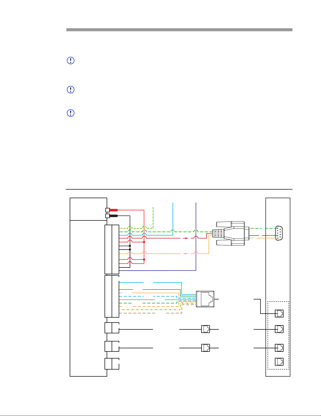
User Guide DDOC0108-000-A2
Power Supply
CNS4
POWER / RS-232
GBE0
GBE1
GBE2
GBE3
ZeroizeChassis
GND
Reserved
5
2
1
DDOC0108-0025
Test PC
1
2
3
4
5
6
7
8
9
10
11
12
13
1
2
3
4
5
6
7
8
9
10
11
12
13
1
2
3
4
5
6
7
8
9
10
1
2
3
4
5
6
7
8
9
10
28 VDC
28 VDC RTN
Similar to GBE0
Similar to GBE0
Keyed for GBE1
Keyed for GBE2
Not Used
Keyed for GBE0
Ethernet Patch Cable
Ethernet Patch Cable
Ethernet Patch Cable
Serial
Data
Port
Ethernet
Ports
AA+
AA-
AB+
AB-
AC+
AC-
AD+
AD-
Operation
6.1 Lab Setup / Connections
NOTE
If the optional lab cables are not used, the user must construct a connection method for their test
set up. Refer to paragraph B.1 Power / RS-232 and paragraph B.2 Ethernetfor connector and
signal information.
NOTE
The CNS4 is powered by a user-supplied 28 VDC power supply and does not have a power switch
of its own. The CNS4 is powered up by turning on the 28 VDC supply.
NOTE
Anytime the CNS4 is powered off, the user must wait at least 30 seconds to re-apply power. This
gives the internal 5 second holdup capacitor circuit time to discharge properly.
1. If not previously accomplished, connect the following cables to the CNS4 front panel
connectors (Figure 6.1).
• Power / RS-232 lab cable: Power
• Ethernet lab cable (keyed for GBE0): GBE0
• Ethernet lab cable (keyed for GBE1): GBE1
• Ethernet lab cable (keyed for GBE2): GBE2
• Ethernet lab cable (keyed for GBE3): GBE3
Figure 6.1 CNS4 Test Setup
CNS4 CSfC 6 - 1 Operation
Revision 1.0
Page 46
User Guide DDOC0108-000-A2
2. If not previously accomplished, connect the following cables to the test PC.
• Power / RS-232 cable DB-9 connector: serial data port
• GBE0 Ethernet lab cable: Ethernet port*
• GBE1 Ethernet lab cable: Ethernet port*
• GBE2 Ethernet lab cable: Ethernet port*
• GBE3 Ethernet lab cable: Ethernet port*
* Use Ethernet patch cable between Ethernet lab cable port and test PC Ethernet port
3. If not previously accomplished, connect the following cables to the 28VDC power supply.
• Power / RS-232 lab cable red banana plug: 28 VDC power supply positive (+) output.
• Power / RS-232 lab cable black banana plug: 28 VDC power supply return (-) output
4. Turn on 28 VDC power supply.
6.2 Basic Operation
6.2.1 Initial Configuration
Initial configuration must be performed through the user's admin account.
6.2.1.1 Time
The time and date appear in some status displays and messages. To display the current date and
time, type:
cns>
sysdate
NOTE
In the example shown below, -d option xx/xx/xx is the desired date and -t option is desired time
If the date or time needs to be corrected, type:
cns>
sysdate -d xx/xx/xx -t xx:xx;xx
6.2.1.2 Passwords
NOTE
The admin account has configuration privileges while the user account has access to only network
storage functionality.
To change admin account password, type
cns>
password -u admin -p [desired password]
To change user account password, type
cns>
password -u user -p [desired password]
The CNS4 software will prompt for the new password when -p command is used.
6.2.2 Communications
The RS-232 serial port link is provided via the CNS4 power connector. A terminal emulation
program (putty, minicom, hyperterminal) is used to communicate with the Command Line Interface
(CLI) using the RS-232 port. Serial port accesses is recommended for initial configuration of the
CNS4. The terminal emulation program should be set to 115200 bps, 8 bits, no parity, one stop bit,
and no flow control.
CNS4 CSfC 6 - 2 Operation
Revision 1.0
Page 47
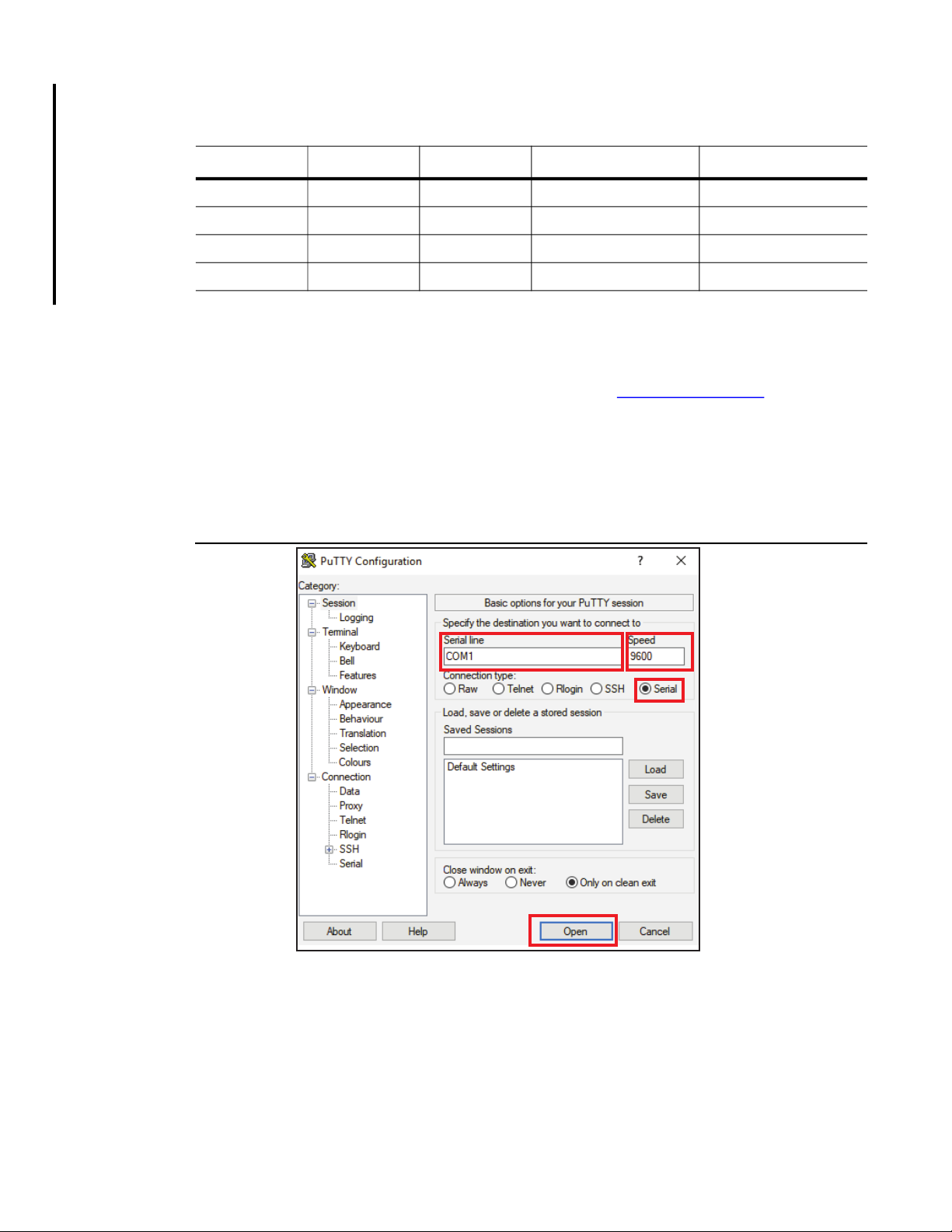
User Guide DDOC0108-000-A2
The CLI is also accessible via Ethernet using Secure Shell (SSH). The default IP addresses are
shown in Table 6.1.
Table 6.1 Ethernet Interfaces
Connector Port Interface IP Address Subnet Mask
GBE0 Port 0 eth0 192.168.0.1 255.255.255.0
GBE1 Port 1 eth1 192.168.1.1 255.255.255.0
GBE2 Port 2 eth2 192.168.2.1 255.255.255.0
GBE3 Port 3 eth3 192.168.3.1 255.255.255.0
Simple Network Management Protocol (SNMP) is also available to communicate with the CNS4.
See Simple Network Management Protocol section for details.
6.2.2.1 Terminal Emulation
A copy of the PuTTY terminal emulator can be obtained from https://www.putty.org/
.
This section explains setting up communications using serial communication (RS-232) and a
PuTTY terminal emulator.
1. If not previously accomplished, download a copy of the PuTTY terminal emulator and install on
computer.
2. Open PuTTY terminal emulator (Figure 6.2).
Figure 6.2 PuTTY Terminal Emulator
DDOC0108-0032
3. Configure PuTTY as follows:
• Serial line: COM1
• Speed: 115200
• Connection type: Serial
4. Click Open button.
A terminal screen should activate.
CNS4 CSfC 6 - 3 Operation
Revision 1.0
Page 48
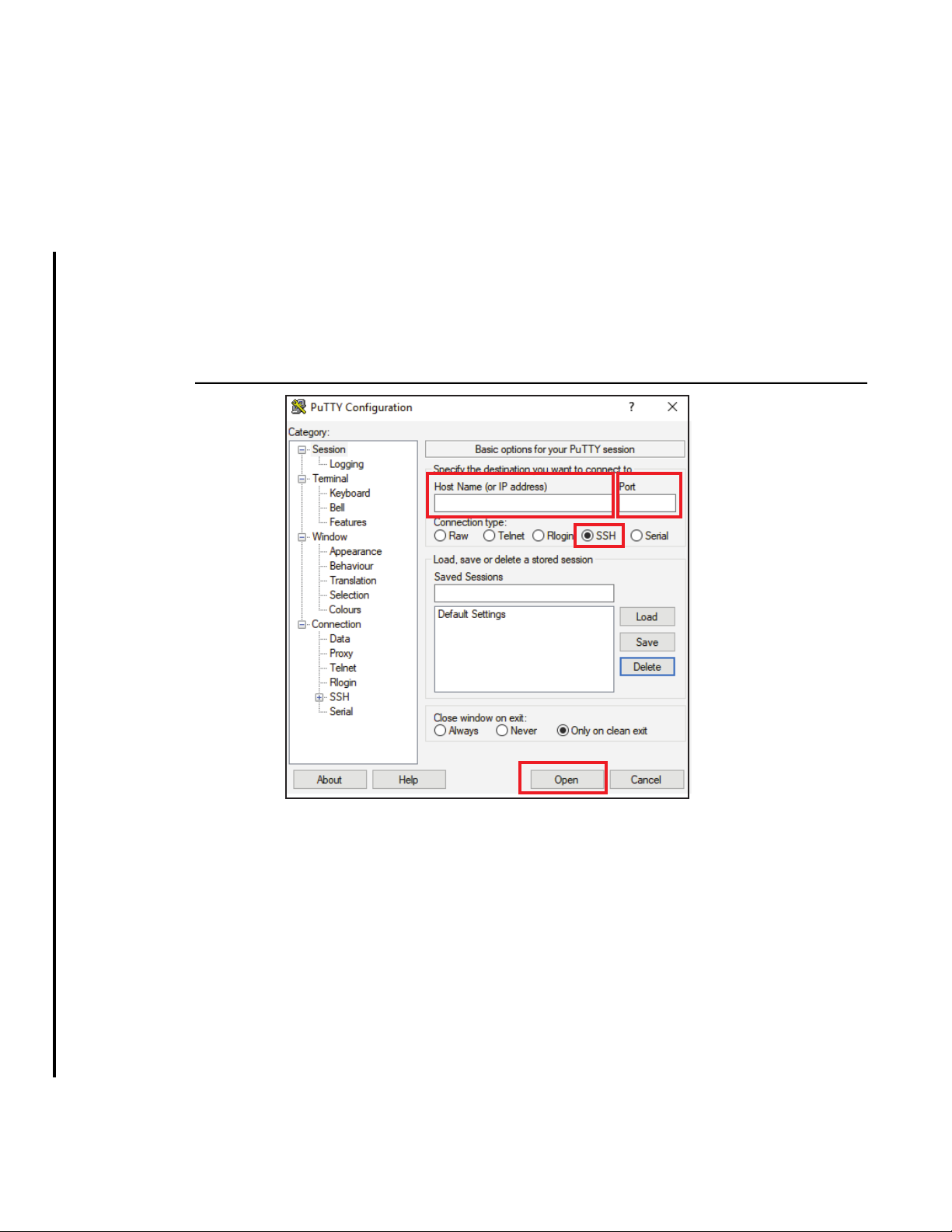
User Guide DDOC0108-000-A2
DDOC0108-0045
5. Click Enter button.
A login prompt should activate.
6. Log into the CLI as follows:
a. At the cns login prompt type admin.
b. At the password prompt type istrator.
6.2.2.2 Ethernet
This section explains setting up communications using secure shell (SSH) and a PuTTY terminal
emulator.
1. If not previously accomplished, download a copy of PuTTY terminal emulator and install on
computer.
2. Open PuTTY terminal emulator (Figure 6.3).
Figure 6.3 PuTTY Terminal Emulator (SSH)
3. Configure PuTTY as follows:
• Connection Type: SSH
• Port:
• Host Name (or IP Address): see Table 6.1
4. Click Open button.
A terminal screen should activate.
5. Click Enter button.
A login prompt should activate.
6. Log into CLI as follows:
a. At the login prompt type admin.
b. At the password prompt type istrator.
CNS4 CSfC 6 - 4 Operation
Revision 1.0
Page 49

User Guide DDOC0108-000-A2
6.2.3 Account Management
The CNS4 has two accounts:
• admin (default password is istrator)
• user (default password is password)
The admin account is used to setup and configure the unit via the CLI. The user account can only
access the drives and cannot change or update any operational parameters.
The hardware encryption layer can have up to five accounts as follows:
• crypto officer (one account)
• user (up to four accounts)
These accounts are independent of the CNS4 / software encryption accounts. Refer to paragraph
6.4.2 Hardware Encryption Layer for additional information.
The software encryption layer has one account. Refer to paragraph 6.4.3 Software Encryption for
additional information.
6.2.4 Storage Media
The CNS4 provides a versatile user-configurable storage system. This section provides some
examples of different configurations. The FSM-C modules are configured through the CLI using
the sysconfig command. The user should determine the following configuration attributes.
• Will there be a RAID configuration.
• Which FSM-C modules to use for a RAID.
• How many and what size partitions to configure.
• What services (iSCSI, NAS) to assign to which partitions.
6.2.4.1 Preparation
Before any attempt to configure or reconfigure the storage system be sure the NAS services are
stopped and unmounted.
• Use CLI command serv --nas 0 to stop NAS service.
• Use CLI command sysconfig -u to unmount drives.
6.2.4.2 Assigning Services to Partitions
The list below shows the Network Attached Storage (NAS) services available with the CNS4.
• Common Internet File System (CIFS)
• Dynamic Host Configuration Protocol (DHCP)
• File Transfer Protocol (FTP)
• HyperText Transfer Protocol (HTTP)
• Internet Small Computer System Interface, (iSCSI)
• Network File System (NFS)
• Secure Shell Protocol (SSH)
• Simple Network Management Protocol (SNMP)
Only SSH is enabled by default. All other services are disabled. See paragraph 11.2.23 serv for
how to enable other service.
6.2.4.3 Preparation
Before any attempt to configure or reconfigure the storage system be sure the NAS services are
stopped and unmounted.
• Use CLI command serv --nas 0 to stop NAS service.
• Use CLI command sysconfig -u all to unmount drives.
CNS4 CSfC 6 - 5 Operation
Revision 1.0
Page 50
User Guide DDOC0108-000-A2
6.2.4.4 Creating a RAID
The CNS4 supports RAID configurations. Once the initial RAID is configured, it is labeled as
fsm_raida. If a second RAID is configured, it will be labeled fsm_raidb. Assigning services to
partitions of a RAID is done in the same manner shown in the previous examples, shown here as
two 50% partitions for NAS over both FSM-C within the RAID1.
cns> sysconfig --raid1 fsm0-d1 fsm0-d2 2 50% 50% -W
[sysconfig]
Create_raid: status=OK
Partition_disk: status=OK
[!sysconfig] OK
6.2.4.5 Partitioning
NOTE
Partitioning is based on user-accessible capacity (referenced as 100%). The actual capacity available is approximately 90% of the stated drive size. A 2 TB dive will have approximately 1862GB
available for user access /storage.
The command shown below is an example of creating two partitions on FSM0, each containing
50% of the drive capacity. For additional information on partitioning, refer toparagraph 7.21 part.
cns> sysconfig --part fsm0 2 50% 50% -w
[sysconfig]
Partitions: numPartitions:2
Partition 0:FSM0 fsm0-d0 Part:1 of 2 Size 50% 1000GB Unconfigured
Partition 1:FSM0 fsm0-d0 Part:2 of 2 Size 50% 1000GB Unconfigured
[!sysconfig] OK
6.2.4.6 Assign NAS Service
To assign NAS services the command sysconfig --nas is applied. Option are used to select
partitions to command / flag is applied to. The options are:
• <#parts> Number of partitions to use with the device.
• <part #> Partition number (can have multiple partitions).
• --all All partitions used with device
In the example below, the NAS is assigned to partition 0.
Example.
cns> sysconfig --nas 1 0
[sysconfig]
DiskConfig:
Individual_disks: numDisk=4
Disk0: name=fsm0-d0 size=2000GB
Raid_disks: numDisk=0
Raid_volumes: numDisk=0
Partitions: numPartitions=1
Part0: name=fsm0-d0 size=2000246MB pSize=100.00% dp=1 numServ=1 sName=fsm_nas0 fmt=no mnt=0
enb=0 swe=no
--- Device Partitions --NAS on partition 0
[!sysconfig] OK
CNS4 CSfC 6 - 6 Operation
Revision 1.0
Page 51
User Guide DDOC0108-000-A2
6.2.4.7 Format Partitions
Once the storage media configuration task is done, the sysconfig -F command is issued to activate
the configuration. The example below shows the command to use to format all NAS partitions by
using the --all flag. A specific partition number can be entered if desired.
cns> sysconfig --format --all
[sysconfig]
FSM_NAS0: cmd=format status=OK
FSM_NAS1: cmd=format status=OK
[!sysconfig] OK
6.2.4.8 Mounting NAS Partition
Once formatting is completed, all partitions that were formatted can be mounted with the sysconfig
-M command. Any configured partitions not formatted will result in an error report, while all
formatted partitions will be mounted.
cns>
sysconfig --mount --all
[sysconfig]
FSM_NAS0: mounted=1 status=OK
FSM_NAS1: mounted=1 status=OK
[!sysconfig] OK
6.2.4.9 Verification
To verify the CNS4 configuration, type sysconfig --status. The response will show the
current configuration.
6.2.5 Health
The CNS4 has internal sensors to monitor critical environmental and operational parameters.
When activated, the health command displays health information for the CNS unit. FSM-C status,
system status and network status can be displayed depending on the chosen suffix / attribute. See
paragraph 11.2.13 health for additional information.
NOTE
The CNS4 S0 LED will turn on if any of the values exceed the listed limits.
Temperature and voltage values will be displayed. The following tolerances are applicable:
1.8 VDC Nominal
Low Limit: 1.60 VDC
High Limit: 2.00 VDC
3.3 VDC Nominal
Low Limit: 2.70 VDC
High Limit: 3.60 VDC
5.0 VDC Nominal
Low Limit: 4.60 VDC
High Limit: 5.50 VDC
12 VDC Nominal
Low Limit: 11.0 VDC
High Limit: 13.0 VDC
Temperature
Normal: 35 to 60 ºC
High: 90 ºC
Low: -40 ºC
CNS4 CSfC 6 - 7 Operation
Revision 1.0
Page 52

User Guide DDOC0108-000-A2
[health]
SYSTEM: Date=04/01/2018 Time=00:00:01 Firmware Ver=1.1 CNS
Ver=2.42-car
Power Supply Temp 1 = 46 C Temp 2 = 38 C
Main Board Temp Bot 1 = 38 C Temp Bot 2 = 39 C
Main Board Temp Top 1 = 36 C Temp Top 2 = 40 C
flash=rw Boot Flash=rw FSM EEPROM=rw pbit_status=OK
|----------------------- FSM Status ----------------------|
| | Temp | 5V | 3.3V | Fault LED | Status LED |
|--------|------|-------|-------|---------- |-------------|
| FSM0 | 35 C | 4.87V | 3.29V | OFF | OFF |
| FSM1 | 34 C | 4.87V | 3.31V | OFF | OFF |
| FSM2 | 35 C | 4.89V | 3.29V | OFF | OFF |
| FSM3 | 35 C | 4.87V | 3.30V | OFF | OFF |
|---------------------------------------------------------|
ETH_0: ip=192.168.0.1 link=1000Mb/s status=OK
ETH_1: ip=192.168.1.1 link=1000Mb/s status=OK
ETH_2: ip=192.168.2.1 link=1000Mb/s status=OK
ETH_3: ip=192.168.3.1 link=1000Mb/s status=OK
|----------------------- ILE Status-----------------------|
| Voltages | Status |
|------|--------------------|-----------------------------|
|Temps | 5V | 3.3V | 1.8V | Zero | Key | Tamper | Alarm |
|------|------|------|------|------|-----|--------|-------|
|38,40 | 4.94V| 3.31V| 1.81V| 0 | 1 | 0 | 0 |
|---------------------------------------------------------|
[!health] OK
The ILE status is shown at the bottom of the text box above. The value for each of the ILE status
items will have a value of 1 or 0.
• Zero = 1, the ILE is currently zeroizing. Will get reset back to 0 when zeroization is complete.
• Key = 1, the key is present on the ILE. Key= 0, key is absent.
• Tamper = 1, the ILE has lost the key. Tamper=0, all is well.
• Alarm = 1, the ILE is in an error state, run the cm_log command to determine the problem.
While the ILE is in the error state, the user will be locked out of the ILE account. Depending on the
reason of the hard error state, the only way to overcome the lockout is to power cycle or zeroize
the ILE.
6.2.6 Built-In Test
The built-in tests monitor CNS4 health. If any of the monitored items listed below fails, a
description of the failure is written to a log file. See paragraph 11.2.19 log for additional
information.
6.2.6.1 CBIT (Continuous Built-In Test)
The following items are monitored by the CBIT. The CBIT runs in the background and cannot be
initiated by the user. If any item is outside of tolerance range, the CNS4 S0 LED will illuminate.
See log paragraph 11.2.19 log for information on how to determine the error.
• Main Carrier Temperature.
• Power Supply Temperature.
• FSM-C Voltage Levels (5V & 3.3V rails).
• Super I/O Voltage (3.3V & 12V rails, plus two Marvell controller voltage levels).
• Processor (CPU Voltage, 12V & 5V rails, plus the AA sized battery voltage).
6.2.6.2 IBIT (Initiated Built-In Test)
The following items are monitored by the IBIT. The IBIT must be initiated by the user using the ibit
command. If any item is outside of tolerance range, the CNS4 S0 LED will illuminate. In addition,
the ibit report will show the error. Refer to paragraph 11.2.19 log and paragraph 11.2.15 ibit for
more information.
CNS4 CSfC 6 - 8 Operation
Revision 1.0
Page 53

User Guide DDOC0108-000-A2
The ibit:
• Checks all I2C components.
• Reports all FSM-C voltages (5V & 3.3V rails).
• Reports Super I/O.
• Reported processor sensors.
• Runs S.M.A.R.T. monitor test on each FSM-C module.
• Checks for Ethernet devices (eth0/1/2/3).
6.2.6.3 PBIT (Power-On Built In Test
The following items are monitored by the PBIT. The PBIT runs only at initial power ON and cannot
be initiated by the user. If any item is outside of tolerance range, the CNS4 S0 LED will illuminate.
See paragraph 11.2.19 log for information on how to determine the error.
• Tests 10MB of system memory
• Attempt to communicate with processor
• Check if Ethernet Devices are present
• Check for SATA controller device presence
6.3 Update
The CNS4 operating system and the ILE firmware can be updated. Contact Curtiss-Wright for
information regarding available / applicable update files before performing any updates.
6.3.1 CNS4 Operating System Update
The following files are required to update the CNS4 operating system:
NOTE
Contact Curtiss-Wright to obtain any available / applicable update files The files below refer to
Curtiss-Wright provided files for performing operating system update. The year, month, day, and
ver_#_## are variables that will reflect the update file date and version.
• cnsf_csfc-image_year_month_day-ver_#_##.bin
• cnsf_csfc-image_year_month_day-ver_#_##.gz
• cnsf_csfc-image_year_month_day-ver_#_##.hdr
• cnsf_csfc-image_yyear_month_day-ver_#_##.md5
The fupdate command boots the CNS4 system into a RAM disk image where the user can install a
new CNS4 disk image onto the system. By default the new image file should be copied to fsm0
partition 0 location. Upon logging into the new RAM disk image, a menu of operations to restore
and verify the restoration of a new disk image activates. The disk image is loaded onto must be
configured so it will be able to accept the files (e.g., not configured as a RAID).
1. Reconfigure FSM0 module as follows:
a. Type sysconfig -E. This command will erase the current configuration.
b. Type sysconfig --part fsm0 1 100% -W. This will create a partition on fsm0. One
partition will be created and it will use 100% of the drive.
c. Type sysconfig --nas 1 0. This assigns NAS service to partition 0.
d. Type sysconfig -F --all -m --all. This formats and mounts all NAS partitions.
e. Type serv --nas 1. This starts NAS services and gives the ability to access the storage
from a remote machine. See serv for additional information.
2. Create a folder called firmware within the /fsm_shares/fsm_nas0 folder.
3. Copy update file (e.g., cns4_image_ver2_31.gz) into /fsm_shares/fsm_nas0 folder.
NOTE
The fupdate command loads an image into memory to allow the user to update the boot image on
the unit.
4. Type fupdate and press E
The update utility will start.
CNS4 CSfC 6 - 9 Operation
NTER key.
Revision 1.0
Page 54
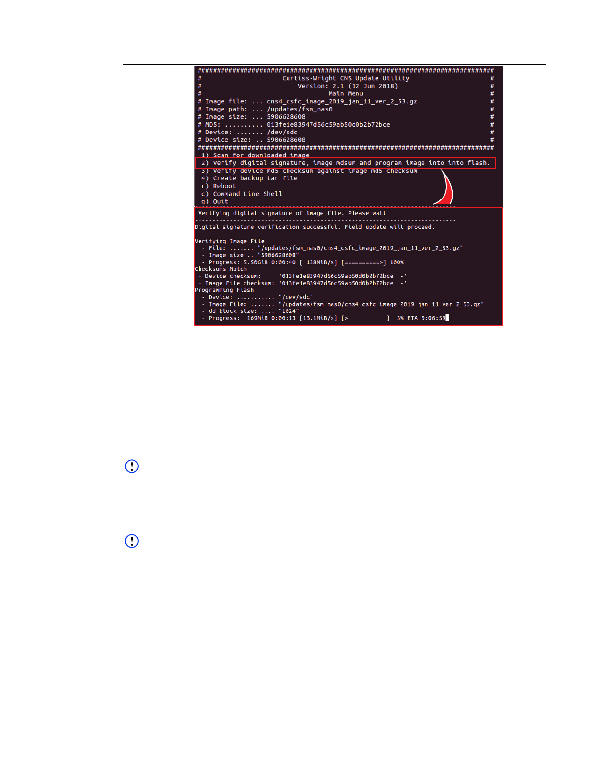
User Guide DDOC0108-000-A2
DDOC0108-0043
Figure 6.4 CNS Update Utility
5. Typically, the update file name should appear above the displayed menu
(e.g.,cns4_csfc_image__year_month_day-ver_#_##.gz).
6. Select 2) Verify digital signature, image mdsum and program image into flash and press
E
NTEr key.
7. The update process will begin and continue for approximately 25 minutes. When the update is
complete, ([!fupdate] OK) will be shown.
8. Cycle the power to store the new image.
6.3.2 ILE Module Firmware
The following files are required to update the ILE firmware:
NOTE
Contact Curtiss-Wright to obtain any available / applicable update files The files below refer to
Curtiss-Wright provided files for performing ILE firmware update. The ver_# is a variable that will
reflect the update file version.
• ile_csfc_ver_#.bin
• signature_ile_csfc_ver_#.bin
NOTE
The disk the firmware update is loaded onto must be configured so it will be able to accept the files
(e.g., not configured as a RAID).
1. Reconfigure FSM-C module as follows:
a. Type sysconfig -E. This command will erase the current configuration.
b. Type sysconfig --part fsm0 1 100% -W. This will create a partition on fsm0. One
partition will be created and it will use 100% of the drive.
c. Type sysconfig --nas 1 0. This assigns NAS service to partition 0.
d. Type sysconfig -F --all -m --all. This formats and mounts all NAS partitions.
e. Type serv --nas 1. This starts NAS services and gives the ability to access the storage
from a remote machine. See serv for additional information.
2. Create a folder called firmware within the /fsm_shares/fsm_nas0 folder.
CNS4 CSfC 6 - 10 Operation
Revision 1.0
Page 55

User Guide DDOC0108-000-A2
DDOC0108-0044
3. On the host Linux PC:
a. Type mkdir -p /tmp/nas_tmp/.
b. Type mount.nfs 192.168.0.1:/fsm_shares/fsm_nas0/ /tmp/nas_tmp/
NOTE
The files below refer to Curtiss-Wright provided files. The year, month, day, and ver_#_## are
variables that will reflect the update file date and version.
4. Type cp ile_csfc_ver_#.bin signature_ile_csfc_ver_#.bin /tmp/nas_tmp/
5. Type umount /tmp/nas_tmp/
NOTE
The cm_field_update command loads an image into memory to allow the user to update the
firmware on the ILE.
6. Type cm_field_update -f ile_csfc_ver_#.bin -s
signature_ile_csfc_ver_#.bin and press E
NTER key.
The update utility will start.
Figure 6.5 ILE Firmware Update
7. The update process will begin and continue for approximately 10 minutes. When the update is
complete, status=OK will be shown.
8. Cycle the power to store the new firmware.
6.4 Encryption
NOTE
Three failed attempts at logging into an encryption layer will block any further attempts until a
power cycle or zeroization is initiated.
The CNS4 uses two methods of encryption:
• Hardware Encryption Layer
• Software Encryption Layer
The zeroize function removes the encryption keys from both layers.
6.4.1 Zeroize
CAUTION
LOSS OF STORED DATA. Pushing the ILE Zeroize button will zeroize the ILE (erase the DEK).
This action will occur even with power off. Data stored on the FSM-C modules will not be
recoverable without using the same exact key as it was encrypted with.
NOTE
The zeroize button is located behind the FIPS CRYPTO cover to ensure it is not accidentally
pressed.
NOTE
The ILE must be zeroized to change the hardware layer password.
The goal of zeroization is to destroy the DEK loaded in the ILE beyond recovery by any means.
Once a zeroize action is initiated, the process will erase the DEK.
The zeroization process is accomplished by one of the following:
• Pushing the ILE zeroize button.
• Issuing a cm_key -z command via the CLI.
• Connecting CNS4 power / RS-232 connector pin 13 to ground for a minimum of 300 mS.
CNS4 CSfC 6 - 11 Operation
Revision 1.0
Page 56

User Guide DDOC0108-000-A2
Zeroization affects only the ILE. The data on the FSM-C modules is still accessible:
• If the FSM-C module can be placed in another CNS4 with the same DEK loaded in its ILE.
• If the DEK can be restored / reloaded.
Data stored on the CNS4 will be encrypted using the ILE module and software encryption on the
FSM-C modules. In addition, data on the FSM-C module can be secured by:
• Physically separating (removing) the FSM-C module from the ILE which holds the encryption
key,
• Zeroizing (erasing) the encryption key (zeroizing the ILE).
In both cases, the encrypted data remains on the FSM-C module, but is unintelligible and
inaccessible. To destroy the data on the FSM-C module, the FSM purge command must be used.
This action actually overwrites all the data on the FSM-C modules. Refer to paragraph 11.2.11
fsmpurge for additional information.
6.4.2 Hardware Encryption Layer
6.4.2.1 LE Account - Internal / External Key Storage
NOTE
DEKs are created in two ways, depending on which Security Mode is selected at login.
The ILE has two security modes (Internal and External). Each mode will define how the Data
Encryption Key (DEK) management is performed. Table 6.2 describes the security modes. The
user may change the security modes as needed.
Table 6.2 Security Modes
Feature
User Authentication Required
User Composed Key
ILE Generated Key
DEK is Internal to the ILE and is Not Accessible to the User
Data Recovery after Power cycle
Data Recovery after Zeroization*
Selectable Storage Location
User Must Execute a Key Transfer Procedure*
* Requires the selection of NOT STORED storage option along with a host to generate and retain the DEK.
Internal
Mode
x x
x
x
x x
x x
External
Mode
x
x
x
• ILE Mode: security mode type. The security mode must be selected by user via user interface
on initial power up.
• User Authentication: ILE user authentication is required to access available ILE services.
• Authorized Services: ILE security modes restrict access to services until the user is identified
and granted access to perform requested service (identity based authorization).
• DEK Generation: method used to create the encryption key. The DEK may be created by the
ILE (Internal Mode) or by the host and sent to the ILE (External Mode).
• DEK Transport: is how the DEK is moved from the user's storage place to the ILE. If DEK
management is handled by the ILE host (External Mode) then the DEK must be passed to the
ILE via RS-232 or I2C. This DEK is passed in an encrypted form and may then be stored on
the ILE. When the ILE controls DEK management, the DEK is created by the ILE (Internal
Mode) and stored on the ILE. Therefore, the DEK never passes outside the ILE unit.
• DEK Storage Location: is how and where the DEK is stored. The user selects one of three
storage options for the DEK (Not stored, SRAM, or EEPROM) when using the Internal or
External Mode.
CNS4 CSfC 6 - 12 Operation
Revision 1.0
Page 57
User Guide DDOC0108-000-A2
6.4.2.2 Internal Security Mode
The DEK is generated by the ILE's RNG to create a 256-bit DEK. It is stored in the ILE EEPROM,
SRAM, or not stored per the user's selection at login. The not stored selection requires a new DEK
be generated at each power-on cycle.
Advantages:
• Requires less effort on the user's part.
• Creates a DEK known and stored exclusively by the ILE.
Disadvantages:
• Stored data lost if ILE is zeroized.
6.4.2.3 External Security Mode
In the External Security Mode the user is required to use their host computer to create four DEKs,
along with their corresponding Message Authentication Code (MAC). It is recommended that the
user utilize software that allows the entry or generation of DEKs (32 bytes long, plus an 8-byte
Initialization Vector, terminated with pressing E
NTER key) using an AES-ECB-256 key wrap
encryption algorithm and generates the corresponding MAC (32 bytes) using an HMACSHA-256
algorithm.
The software should also handle the transmission of each of the four required DEK packages
(DEK of 64 ASCII hex characters, plus an Initialization Vector of 16 ASCII hex characters,
terminated with pressing E
NTER key). The initialization vector provides the required information to
unwrap the package and extract the KEK. The DEKs are stored in the EEPROM or SRAM, or
None (not stored on the ILE) per the user's selection at login. The None selection retains the DEK
on the host.
Advantages:
• Stored data retained / accessible if ILE is zeroized (as long as DEK has been retained).
• Creates a custom DEK created and known by the user.
Disadvantages:
• Requires more effort on the user's part.
6.4.2.4 ILE Account Creation
NOTE
The ILE must be zeroized to change the hardware layer password.
NOTE
The first account created on the ILE is always the administrator / crypto officer account. Four
additional user accounts can be created as well.
After the CNS4 has been initially configured, the administrator / crypto officer may create up to four
additional user accounts using the cm_create_account command. The accounts must comply with
the following considerations.
• User name
• Composed by the user
• Must be 16 characters maximum, 8 characters minimum.
• Password
• Composed by the user
• Must be 8 to 64 character
• Must contain at least one number
• Must have one upper and one lower case letter
• Cannot contain symbols.
• Mode. The mode will be either internal or external. See Security Mode above.
• Transfer. If external mode is selected, the DEK can be either plain text or encrypted using
another key (referred to as Key Encryption Key [KEK]). Use of a KEK provides extra security
when the DEK is transferred.
• Storage. Where the key will be stored; None (not stored), EEPROM or SRAM.
CNS4 CSfC 6 - 13 Operation
Revision 1.0
Page 58
User Guide DDOC0108-000-A2
Examples
Create a crypto officer account with username john, password aBcDeFg1, with internal key generation stored on
the SRAM
cns> cm_create_account -u john -p aBcDeFg1 -m i -k s
[cm_create_account]
user_token=0xab491feccdd158654adab4bb10ddfffe3948571fddeee43f6b7c9a0cc0013693
token_hmac=0xce6256b4220638eefb3bb3c428ddd853353bc9ce3f436062ab59d9fcd9f93642
status=OK
[!cm_create_Account]
Create a crypto officer account with username john, password aBcDeFg1, with external key generation stored on
the EEPROM
cns> cm_create_account -u john -p aBcDeFg1 -m e -k e
[cm_create_account]
user_token=0xc9ed6c3bbc3de43110d4e5b67da39ea4d1d79d1fb269d25759b38a25db0a8552c72
158ebc19e7e60
token_hmac=0x8ba8729d3a22bc6787b404a13f7cbec190ce5f64fc0e770c8710f60318274259
status=OK
[!cm_create_account]
Create a user account with username marty, password gHpErCf7
cns> cm_create_account -u marty -p gHpErCf7
[cm_create_account]
user_token=0xa77650375de646873a61d4c18954d2c4aaf35cd2af59bd9f0646b5a55223011a
token_hmac=0xbd7147c5119728ffea5aa2d517c3c747242ab8ad2e3259561a59d9dbe8e43248
status=OK
[!cm_create_account]
6.4.2.5 ILE Login
The login process is a two-step process where a username and password must first be provided to
login. The second step is to decrypt the user token and use that decrypted user token along with
the provided nonce to generate an HMAC-SHA256 to complete the challenge. Refer to paragraph
11.2.6 cm_login for additional information.
Login with username user, password Password1
cns> cm_login -u user -p Password1
[cm_login]
challenge_nonce=0xf9ccab6b0838c5ab2c1d51085df7cb3a2b9d11b7f7264b39b20116085f6282
55d5c72906af864026f18a7e39e7da5afe2666b839f258a37eb90386a6493726b2
status=OK
[!cm_login]
Complete the login process by submitting the HMAC-SHA256
cns> cm_login --hmac
30fc2e0ced04edb0942b8cae01dc0692e61bfedf172404da45edbaab72fb0791
[cm_login]
challenge_hmac=0x30fc2e0ced04edb0942b8cae01dc0692e61bfedf172404da45edbaab72fb079
1
status=OK
[!cm_login]
6.4.2.6 Key Transfer
NOTE
Key transfer is applicable only if external mode has been selected.
The command example below transfers the PSK and DEK:
• from the user's equipment to CNS4 ILE 0 (0=first encryptor of four within the ILE).
• in plain text (non-encrypted transfer).
CNS4 CSfC 6 - 14 Operation
Revision 1.0
Page 59
User Guide DDOC0108-000-A2
This command assumes that the external mode was selected in the cm_create_account
command.
The following explanation pertains to both the plain text key and encrypted key transfers. In the
plain text transfer, the user sends the DEK and PSK over the serial or Ethernet user interface. The
encryption process takes place over the backplane between the ILE and its FSM-C modules. In
the encrypted transfer, the user is involved in the encryption of the transfer from their equipment
over the serial or Ethernet interface to the ILE.
When encrypted transfers are required, the transfer package that carries the DEK itself must be
encrypted. Therefore, an encryption key for the transfer package is needed. This encryption key is
referred to as the Key Encryption Key (KEK). This is not a permanent key; it is regenerated each
time a KEK is called for by the cm_key command.
After a zeroization, or on a new ILE, a common encryption key is needed to encrypt and decrypt
the first KEK to the user's equipment from the ILE. This common key is called the PreShared Key
(PSK); it is always available on the ILE. The PSK is used to encrypt all initial transfers to establish
unique encryption keys for subsequent encrypted transfers of keys and their MACs (Message
Authentication Code).
When the ILE receives a KEK command, the KEK is generated and packaged for transfer. This
package is encrypted using the previous KEK (referred to as an old or retired KEK; the PSK is
used if it is the first KEK cmd. for the unit) and sent to the user's equipment. The corresponding
MAC is generated in the same manner and sent to the user's equipment. The user's equipment
has the old KEK and the PSK and uses the appropriate key to decrypt the KEK package and the
MAC, which is used to verify that the KEK is correct. The KEK is only used once per DEK transfer
session and then retired. Once this process is completed, a KEK is available to encrypt the DEK
and send it to the ILE. Refer to paragraph 5.16 External Key Passing Example or a step-by-step
example.
6.4.3 Software Encryption
NOTE
The passphrase can be any ASCII printable character
NOTE
Changing the SWE passphrase renders the data in SWE container useless.
6.4.3.1 Software Encryption Container
The swcrypt command allows the user to view and alter the CNS disk encryption options. Software
Encryption (SWE) uses containers to hold the data. Creation of a container requires the use of a
passphrase. The passphrase must include the conditions listed below:
• Minimum characters: 15.
• Minimum numbers: 1.
• Minimum lowercase characters: 1.
• Minimum uppercase characters: 1.
• Minimum special characters: 1.
• Maximum consecutive repeating characters: 2.
• Maximum consecutive repeating characters of the same class: 4.
• Minimum number of different characters: 8.
• Minimum days for passphrase change: 1.
• Maximum days for password change: 60.
• Dictionary words are not valid or accepted.
• The last seven passphrases cannot be reused.
NOTE
Keyfiles should not be used in high threat environments.
After the passphrase has been decided upon, it can be:
• typed in when prompted.
• saved a keyfile.
CNS4 CSfC 6 - 15 Operation
Revision 1.0
Page 60

User Guide DDOC0108-000-A2
To generate the keyfile, the passphrase is enter as a text file and then saved to the CNS4 keyfile
directory. After the keyfile is saved to the CNS4, a SWE container must be created using the --init
flag before it can be opened, closed or erased. The --flag is applied to partitions. The example
shown below is creating a SWE container on partition 2.
Example
cns> swcrypt --init 2 --key-file /keyfiles/keyfile2.txt
[swcrypt]
cmd=init Part=2 status=OK
[!swcrypt] OK
After the SWE container has been created, the following command and flags are used;
• swcrypt --open will open a SWE container.
• swcrypt --close will close a SWE container.
• swcrypt --erase will erase a SWE container.
These commands / flags typically have an option included with them. The option is used to select
partitions to command / flag is applied to. The options are:
• # - single NAS disk volume number
• # # - <# #> two or more NAS disk volumes
• all - all NAS disk volumes
The example below opens a SWE container on partition 2 by manually entering the passphrase.
Example
cns> swcrypt --open 2 --pass
[swcrypt]
cmd=open Part=2 Enter passphrase for /dev/sdb1:
Verify passphrase:
status=OK
[!swcrypt] OK
The example below opens a SWE container on partition 2 using a keyfile.
Example
cns> swcrypt --open 2 --key-file /keyfiles/keyfile2.txt
[swcrypt]
cmd=open Part=3 status=OK
[!swcrypt] OK
The status of the SWE container can be checked by using the swcrypt command without any
associated flags. The example show below shows no SWE containers on partitions 1 and 2. The
container on partition 3 is open while the container on partition 4 is closed.
Example
cns> swcrypt
[swcrypt]
Partitions: 4
Part0: name=fsm0-d01 swe=no
Part1: name=fsm1-d01 swe=no
Part2: name=fsm2-d01 swe=open
Part3: name=fsm3-d01 swe=closed
[!swcrypt] OK
Additional information regarding command associated with the software encryption layer is
available in paragraph 11.2.25 swcrypt and the Quick Start section
CNS4 CSfC 6 - 16 Operation
Revision 1.0
Page 61

User Guide DDOC0108-000-A2
System Configuration
The system configuration command (sysconfig) is used to either:
• View the system configuration
• Create or modify the system configuration
Refer to Table 7.1 for a list of flags and options associated with the sysconfig command.
Table 7.1 Sysconfig Flags and Options
Flag Modifier Action
--add
-A --all
--file
-F --format
--free
-K --fsck
--fsep
--getDevName
--getFreeDisks
--getNfsOpt
-h --help
-L --hide
--iscsi0
--iscsi1
--iscsi2
--iscsi3
--isMounted
-M --mount
--multi
--nas
--numFreeDisks
--numFsmDisks
--numPartitions
--part
--raid
--raidStatus
--remove
--rescan
--scan
--setNfsOpt
-S --status
--sw
-T --trim
-U --umount
--verb
--version
-E --wipe
--wrap
-W --writecfg
<options> Add spare / replace disk in RAID
Show all fields even empty ones
<options> Allocate a target image file on a mounted NAS volume
<#|# #|all> Format NAS partition(s)
<options> Free partition not used for service
<#|# #|all> File system check one or more NAS partitions
"char" Specify field separation character for single line machine output
<str> Get device name of specified NAS volume
Get list of unconfigured disks
Get current NFS export flags
Show sysconfig help file
Hide most of the field labels
<options> iSCSI on assigned partition using GBE0
<options> iSCSI on assigned partition using GBE1
<options> iSCSI on assigned partition using GBE2
<options> iSCSI on assigned partition using GBE3
<VID> Check to see if NAS volume is mounted
<#|# #|all> Mount partition(s) as NAS
Used with assign services flag to allow multiple services to use the same
partition
<options> Network attached storage
Get number of free disks
Get total number of disks
Get total number of partitions
<options> Create partition(s) on specified FSMs
<L> <options> Create RAID across specified FSMs
Display status of each RAID in the system
<options> Remove spare defective disk from a raid
Rescan SATA hosts for FSM connections
Delete and then scan for FSM connections
<options> Set NFS export flags
Show disk, partition, and service configuration
Generate single line machine output
<#|# #|all> Trim one or more mounted NAS partitions
<#|# #|all> Unmount NAS partition(s)
Generate verbose output
Show software version
Wipe RAID and partition data from all disks
<1, 0> Word wrap text to screen
Write system configuration to disks
CNS4 CSfC 7 - 1 System Configuration
Revision 0.0
Page 62

User Guide DDOC0108-000-A2
7.1 add
Purpose
Add spare disk / replace disk in RAID
Command
sysconfig --add fsm_raid<c> fsm<slot>-d<pos>
Flag Modifiers Explanation
<c> - Raid disk identifier (a,b,c,d,etc)
<slot> - FSM slot number
<pos> - Disk in specified position in FSM
Example
cns> sysconfig --add fsm_raida fsm0-d3
[sysconfig]
Add_spare: raid=/dev/md/fsm_raida disk=/dev/fsm0-d3 status=OK
[!sysconfig] OK
7.2 all
Purpose
Show all fields, even empty ones. Typically used as a modifier to the stats command.
Command
sysconfig --status --all
Flag Modifiers Explanation
Not Applicable
Example
cns> sysconfig --status --all
[sysconfig]
DiskConfig:
Unconfigured_disks: numDisk=0
Individual_disks: numDisk=0
Raid_disks: numDisk=4
Disk0: name=fsm0-d0 size=512GB
Disk1: name=fsm0-d1 size=512GB
Disk2: name=fsm0-d2 size=480GB
Disk3: name=fsm0-d3 size=512GB
Raid_volumes: numDisk=1
Raid0: name=fsm_raida level=0 size=2016GB numDisk=4 disk=fsm0-d0 \disk=fsm0-d1
disk=fsm0-d2 disk=fsm0-d3
Partitions: numPartitions=6
Part0: name=fsm_raida size=322629MB pSize=16.00% dp=1 numServ=1 \sName=fsm_nas0
fmt=ext4 mnt=1 enb=0
Part1: name=fsm_raida size=322630MB pSize=16.00% dp=2 numServ=1 \sName=fsm_nas1
fmt=ext4 mnt=0 enb=0
Part2: name=fsm_raida size=342794MB pSize=17.00% dp=3 numServ=1 \sName=FC0_L0
enb=0
Part3: name=fsm_raida size=342794MB pSize=17.00% dp=4 numServ=1 \sName=FC1_L0
enb=0
Part4: name=fsm_raida size=342794MB pSize=17.00% dp=5 numServ=1 \sName=iSCSI0_L0
enb=0
Part5: name=fsm_raida size=342794MB pSize=17.00% dp=6 numServ=1 \sName=iSCSI1_L0
enb=0
Device_partitions: numServ=5
NAS: num_part=2 part=0 part=1
FC0: num_part=1 part=2
FC1: num_part=1 part=3
iSCSI0: num_part=1 part=4
iSCSI1: num_part=1 part=5
Image_files:
[!sysconfig] OK
CNS4 CSfC 7 - 2 System Configuration
Revision 0.0
Page 63

User Guide DDOC0108-000-A2
7.3 file
Purpose
Allocate a target image file on a mounted NAS volume
Command
sysconfig --file <nas volume #> <image file name> <image size>
Flag Modifiers Explanation
<NAS volume #> - NAS volume number. 0 to n
<image file name> - Name of target image file on NAS volume.
<image size> - Image size specified in MiB, MB, GiB, GB, TiB or TB.
Example
cns> sysconfig --file 0 file1.img 10GiB
[sysconfig]
DiskConfig:
Raid_disks: numDisk=4
Disk0: name=fsm0-d0 size=512GB
Disk1: name=fsm0-d1 size=512GB
Disk2: name=fsm0-d2 size=480GB
Disk3: name=fsm0-d3 size=512GB
Raid_volumes: numDisk=1
Raid0: name=fsm_raida level=0 size=2016GB numDisk=4 disk=fsm0-d0 \disk=fsm0-d1
disk=fsm0-d2 disk=fsm0-d3
Partitions: numPartitions=6
Part0: name=fsm_raida size=322629MB pSize=16.00% dp=1 numServ=1 \sName=fsm_nas0
fmt=ext4 mnt=1 enb=0
Part1: name=fsm_raida size=322630MB pSize=16.00% dp=2 numServ=1 \sName=fsm_nas1
fmt=ext4 mnt=1 enb=0
Part2: name=fsm_raida size=342794MB pSize=17.00% dp=3 numServ=1
\sName=Unconfigured
Part3: name=fsm_raida size=342794MB pSize=17.00% dp=4 numServ=1
\sName=Unconfigured
Part4: name=fsm_raida size=342794MB pSize=17.00% dp=5 numServ=1 \sName=iSCSI0_L0
enb=0
Part5: name=fsm_raida size=342794MB pSize=17.00% dp=6 numServ=1 \sName=iSCSI1_L0
enb=0
Device_partitions: numServ=3
NAS: num_part=2 part=0 part=1
iSCSI0: num_part=1 part=4
iSCSI1: num_part=1 part=5
Image_files:
Vol0: numFiles=1 name=file1.img size=10737MB
[sysconfig] OK
7.4 format
Purpose
Format NAS partition(s)
Command
sysconfig --format <# | ## | all>
Flag Modifiers Explanation
# - single NAS disk volume number
# # - <# #> two or more NAS disk volumes
all - all NAS disk volumes
Example
cns> sysconfig --format all
[sysconfig]
FSM_NAS0: cmd=format status=OK
FSM_NAS1: cmd=format status=OK
[!sysconfig] OK
CNS4 CSfC 7 - 3 System Configuration
Revision 0.0
Page 64

User Guide DDOC0108-000-A2
7.5 free
Purpose
Free partition not used for service
Command
sysconfig --free <# parts (0-n)> <part #>
Flag Modifiers Explanation
<#parts> Number of partitions to use with the device.
<part #> Partition number (can have multiple partitions)
Example
cns> sysconfig --free 2 2 3
[sysconfig]
DiskConfig:
Raid_disks: numDisk=4
Disk0: name=fsm0-d0 size=512GB
Disk1: name=fsm0-d1 size=512GB
Disk2: name=fsm0-d2 size=480GB
Disk3: name=fsm0-d3 size=512GB
Raid_volumes: numDisk=1
Raid0: name=fsm_raida level=0 size=2016GB numDisk=4 disk=fsm0-d0 \disk=fsm0-d1
disk=fsm0-d2 disk=fsm0-d3
Partitions: numPartitions=6
Part0: name=fsm_raida size=322629MB pSize=16.00% dp=1 numServ=1 \sName=fsm_nas0
fmt=ext4 mnt=1 enb=0
Part1: name=fsm_raida size=322630MB pSize=16.00% dp=2 numServ=1 \sName=fsm_nas1
fmt=ext4 mnt=1 enb=0
Part2: name=fsm_raida size=342794MB pSize=17.00% dp=3 numServ=1
\sName=Unconfigured
Part3: name=fsm_raida size=342794MB pSize=17.00% dp=4 numServ=1
\sName=Unconfigured
Part4: name=fsm_raida size=342794MB pSize=17.00% dp=5 numServ=1 \sName=iSCSI0_L0
enb=0
Part5: name=fsm_raida size=342794MB pSize=17.00% dp=6 numServ=1 \sName=iSCSI1_L0
enb=0
Device_partitions: numServ=3
NAS: num_part=2 part=0 part=1
iSCSI0: num_part=1 part=4
iSCSI1: num_part=1 part=5
Image_files:
[!sysconfig] OK
7.6 fsck
Purpose
File system check one or more NAS partitions
Command
sysconfig --fsck <# | ## | all>
Explanation
# - single NAS disk volume number
# # - <# #> two or more NAS disk volumes
all - all NAS disk volumes
Example
cns> sysconfig --fsck all
[sysconfig
FSM_NAS0: cmd=fsck status=OK
FSM_NAS1: cmd=fsck status=OK
[!sysconfig] OK
CNS4 CSfC 7 - 4 System Configuration
Revision 0.0
Page 65

User Guide DDOC0108-000-A2
7.7 fsep
Purpose
Specify field separation character for single line machine output
Command
sysconfig --fsep “char”
Flag Modifiers Explanation
“char” - designates a character to act as a separator between fields.
7.8 getDevName
Purpose
Get device name of specified NAS volume
Command
sysconfig --getDevName <str>
Flag Modifiers Explanation
<str> - System name of the NAS volume specified (ie. /dev/fsm0-d0p0 /dev/fsm_raida1)
[Example
cns> sysconfig --getDevName 0
[sysconfig]
/dev/fsm0-d0p1
[!sysconfig] OK
7.9 getFreeDisks
Purpose
Get list of unconfigured disks
Command
sysconfig --getFreeDisks
Flag Modifiers Explanation
Not Applicable
Example
cns> sysconfig --getFreeDisks
[sysconfig]
/dev/fsm0-d0 /dev/fsm0-d1 /dev/fsm0-d2 /dev/fsm0-d3
[!sysconfig] OK
7.10 getNfsOpt
Purpose
Get current NFS export flags
Command
sysconfig --getNfsOpt
Flag Modifiers Explanation
Not Applicable
Example
cns> sysconfig --getNfsOpt
[sysconfig]
nfs_export_flags=rw,sync,no_root_squash,anonuid=1000,anongid=1000 status=OK
[!sysconfig] OK
CNS4 CSfC 7 - 5 System Configuration
Revision 0.0
Page 66

User Guide DDOC0108-000-A2
7.11 help
Purpose
Show sysconfig help file
Command
sysconfig --help
Flag Modifiers Explanation
Not Applicable
7.12 hide
Purpose
Hide most of the field labels
Command
sysconfig --status --hide
Flag Modifiers Explanation
Not Applicable
Example
cns> sysconfig --hide
[sysconfig]
DiskConfig:
Unconfigured disks: 1
Disk0: fsm0-d2 480GB
Individual disks: 1
Disk0: fsm0-d3 512GB
Raid disks: 2
Disk0: fsm0-d0 512GB
Disk1: fsm0-d1 512GB
Raid volumes: 1
Raid0: fsm_raida level=0 1024GB numDisk=2 fsm0-d0 fsm0-d1
Partitions: 6
Part0: fsm0-d3 128027MB 25.00% dp=1 fsm_nas0 fmt=ext4 mnt=1 enb=0 FC1_L0 \
enb=0
Part1: fsm0-d3 128027MB 25.00% dp=2 iSCSI0_L0 enb=0
Part2: fsm0-d3 128028MB 25.00% dp=3 fsm_nas1 fmt=ext4 mnt=1 enb=0 iSCSI0_L1 \
enb=0 iSCSI0_L2 enb=0
Part3: fsm0-d3 128027MB 25.00% dp=4 iSCSI1_L0 enb=0
Part4: fsm_raida 512110MB 50.00% dp=1 Unconfigured
Part5: fsm_raida 512110MB 50.00% dp=2 FC0_L0 enb=0
Device_partitions:
NAS: 0 2
FC0: 5
iSCSI0: 1
iSCSI1: 3
Image_files:
Vol0: file.img 10737MB
Vol1: file1.img 10737MB file2.img 5368MB
FC1: numFiles=1 /fsm_shares/fsm_nas0/file.img
iSCSI0: numFiles=2 /fsm_shares/fsm_nas1/file1.img \ /fsm_shares/fsm_nas1/
file2.img
[!sysconfig] OK
7.13 iscsi0, 1, 2, 3
Purpose
Assign a service to a specific partition
Command
sysconfig --iscsiX <# parts> <part #>
Flag Modifiers Explanation
<#parts> Number of partitions to use with the device.
<part #> Partition number (can have multiple partitions)
CNS4 CSfC 7 - 6 System Configuration
Revision 0.0
Page 67

User Guide DDOC0108-000-A2
Example
cns> sysconfig --nas 2 0 1 --fc0 1 2 --fc1 1 3 --iscsi0 1 4 --iscsi1 1 5
sysconfig]
DiskConfig:
Raid_disks: numDisk=4
Disk0: name=fsm0-d0 size=512GB
Disk1: name=fsm0-d1 size=512GB
Disk2: name=fsm0-d2 size=480GB
Disk3: name=fsm0-d3 size=512GB
Raid_volumes: numDisk=1
Raid0: name=fsm_raida level=0 size=2016GB numDisk=4 disk=fsm0-d0 \disk=fsm0-d1
disk=fsm0-d2 disk=fsm0-d3
Partitions: numPartitions=6
Part0: name=fsm_raida size=322629MB pSize=16.00% dp=1 numServ=1 \sName=fsm_nas0
fmt=no mnt=0 enb=0
Part1: name=fsm_raida size=322630MB pSize=16.00% dp=2 numServ=1 \sName=fsm_nas1
fmt=no mnt=0 enb=0
Part2: name=fsm_raida size=342794MB pSize=17.00% dp=3 numServ=1 \sName=FC0_L0
enb=0
Part3: name=fsm_raida size=342794MB pSize=17.00% dp=4 numServ=1 \sName=FC1_L0
enb=0
Part4: name=fsm_raida size=342794MB pSize=17.00% dp=5 numServ=1 \sName=iSCSI0_L0
enb=0
Part5: name=fsm_raida size=342794MB pSize=17.00% dp=6 numServ=1 \sName=iSCSI1_L0
enb=0
Device_partitions: numServ=5
NAS: num_part=2 part=0 part=1
FC0: num_part=1 part=2
FC1: num_part=1 part=3
iSCSI0: num_part=1 part=4
iSCSI1: num_part=1 part=5
Image_files:
Vol0: numFiles=2 file1.img 60927MB file0.img 31875MB
[!sysconfig] OK
7.14 isMounted
Purpose
Check to see if NAS volume is mounted
Command
sysconfig --isMounted <VID>
Flag Modifiers Explanation
[<VID> - NAS volume ID
Example
cns> sysconfig --isMounted 0
[sysconfig]
FSM_NAS0: mounted=1 status=OK
[!sysconfig] OK
7.15 mount
Purpose
Mount NAS partition(s)
Command
sysconfig --mount <#|# #|all>
Flag Modifiers Explanation
# - single NAS disk volume number
# # - <# #> two or more NAS disk volumes
all - all NAS disk volumes
CNS4 CSfC 7 - 7 System Configuration
Revision 0.0
Page 68

User Guide DDOC0108-000-A2
Example
cns> sysconfig --mount all
[sysconfig]
FSM_NAS0: mounted=1 status=OK
FSM_NAS1: mounted=1 status=OK
[!sysconfig] OK
7.16 multi
Purpose
Used with assign services flag to allow multiple services to use the same partition
Command
sysconfig --fc0 1 0 --fc1 1 0 --multi
Flag Modifiers Explanation
Not Applicable
Example
cns> sysconfig --fc0 1 0 --fc1 1 0 --multi
7.17 nas
Purpose
Assign a service to a specific partition
Command
sysconfig --nas <# parts> <part #>
Flag Modifiers Explanation
<#parts> - Number of partitions to use with the device.
<part #> - Partition number (can have multiple partitions).
--all - All partitions used with device.
Example
cns> sysconfig --nas 2 0 1 --iscsi0 1 4 --iscsi1 1 5
sysconfig]
DiskConfig:
Raid_disks: numDisk=4
Disk0: name=fsm0-d0 size=512GB
Disk1: name=fsm0-d1 size=512GB
Disk2: name=fsm0-d2 size=480GB
Disk3: name=fsm0-d3 size=512GB
Raid_volumes: numDisk=1
Raid0: name=fsm_raida level=0 size=2016GB numDisk=4 disk=fsm0-d0 \disk=fsm0-d1
disk=fsm0-d2 disk=fsm0-d3
Partitions: numPartitions=6
Part0: name=fsm_raida size=322629MB pSize=16.00% dp=1 numServ=1 \sName=fsm_nas0
fmt=no mnt=0 enb=0
Part1: name=fsm_raida size=322630MB pSize=16.00% dp=2 numServ=1 \sName=fsm_nas1
fmt=no mnt=0 enb=0
Part2: name=fsm_raida size=342794MB pSize=17.00% dp=3 numServ=1 \sName=FC0_L0
enb=0
Part3: name=fsm_raida size=342794MB pSize=17.00% dp=4 numServ=1 \sName=FC1_L0
enb=0
Part4: name=fsm_raida size=342794MB pSize=17.00% dp=5 numServ=1 \sName=iSCSI0_L0
enb=0
Part5: name=fsm_raida size=342794MB pSize=17.00% dp=6 numServ=1 \sName=iSCSI1_L0
enb=0
Device_partitions: numServ=3
NAS: num_part=2 part=0 part=1
iSCSI0: num_part=1 part=3
iSCSI1: num_part=1 part=4
Image_files:
Vol0: numFiles=2 file1.img 60927MB file0.img 31875MB
[!sysconfig] OK
CNS4 CSfC 7 - 8 System Configuration
Revision 0.0
Page 69

User Guide DDOC0108-000-A2
7.18 numFreeDisks
Purpose
Get number of free disks
Command
sysconfig --numFreeDisks
Flag Modifiers Explanation
Not Applicable
Example
cns> sysconfig --numFreeDisks
[sysconfig]
4
[!sysconfig] OK
7.19 numFsmDisks
Purpose
Get total number of disks seen by the OS in all FSM present with keys loaded
Command
sysconfig --numFsmDisks
Flag Modifiers Explanation
Not Applicable
Example
cns> sysconfig --numFsmDisks
[sysconfig]
4
[!sysconfig] OK
7.20 numPartitions
Purpose
Get total number of partitions
Command
sysconfig --numPartitions
Flag Modifiers Explanation
Not Applicable
Example
cns> sysconfig --numPartitions
[sysconfig]
6
[!sysconfig] OK
7.21 part
Purpose
Create partition
Command
sysconfig --part <device> <num parts (1-n)> <part sizes>
Flag Modifiers Explanation
<device> - FSM device name of disk to create partitions on. (fsmX-dY)
<num parts> - Number of partitions to create on the disk. (1 to n)
<part sizes> - List of partition sizes. Can be specified as percent of disk or sizes in MiB, MB, GiB,
GB, TiB or TB.
CNS4 CSfC 7 - 9 System Configuration
Revision 0.0
Page 70
User Guide DDOC0108-000-A2
Example
cns> sysconfig --part fsm0-d0 2 25% 75% -W
[sysconfig]
Partition_disk: status=OK
[!sysconfig] OK
7.22 raid
Purpose
Create RAID
Command
sysconfig --raid<L> <devices> <num parts> <part sizes>
Flag Modifiers Explanation
<L> - Raid level 0, 1 or 10. Raid 0 if not specified.
<devices> - FSM device names of disks to create raid and partitions on.
<num parts> - Number of partitions to create on the raid.
<part sizes> - List of partition sizes. Can be specified as percent of disk or sizes in MiB, MB, GiB,
GB, TiB or TB.
Example
cns> sysconfig --raid1 fsm0-d1 fsm0-d2 2 50% 50% -W
[sysconfig]
Create_raid: status=OK
Partition_disk: status=OK
[!sysconfig] OK
Example
cns> sysconfig --raid fsm0-d0 fsm0-d1 fsm0-d2 fsm0-d3 6 16% 16% 17% 17% 17% 17% -W
[sysconfig]
Create_raid: status=OK
Partition_disk: status=OK
[!sysconfig] OK
7.23 raidStatus
When a RAID that can operate with a missing disk is built it takes time for the disk to synchronize
the disk contents between disks. The command sysconfig --raidstatus can be used to monitor the
raid state and check the status of the synchronization progress of each raid in the system. The raid
status command reports:
• RAID level
• RAID size
• RAID state
• Number of disks
• Name of each disk device
• Mode of each disk device
If the disk is being synchronized it will report the percentage of synchronization completed, the
estimated time to finish and the speed at which the data is being synchronized.
Purpose
Display status of each RAID in the system
Command
sysconfig --raidStatus
Flag Modifiers Explanation
Not Applicable
CNS4 CSfC 7 - 10 System Configuration
Revision 0.0
Page 71

User Guide DDOC0108-000-A2
Example
cns> sysconfig --raidStatus
[sysconfig]
fsm_raida: level=raid1 size=511.98GB state=active,resyncing active_dev=2
\raid_dev=2 dev=fsm0-d0 dstate=active,sync dev=fsm0-d1 dstate=active,sync
\resync=1.1% finish=71.5min speed=115080K/sec
[!sysconfig] OK
7.24 remove
Purpose
Remove spare defective disk from a raid
Command
sysconfig --remove fsm<slot>-d<pos>
Flag Modifiers Explanation
<slot> - FSM slot number
<pos> - Disk in specified position in FSM
Example
cns> sysconfig --remove fsm0-d3
[sysconfig]
Remove_spare: raid=/dev/md/fsm_raida disk=/dev/fsm0-d3 status=OK
[!sysconfig] OK
7.25 rescan
Purpose
Rescan SATA hosts for FSM connections
Command
sysconfig --rescan
Flag Modifiers Explanation
Not Applicable
Example
cns> sysconfig --rescan
[sysconfig]
cmd=rescan, scanning_for_FSM_disks status=OK
[!sysconfig] OK
7.26 scan
Purpose
Delete and then scan for FSM connections
Command
sysconfig --scan
Flag Modifiers Explanation
Not Applicable
Example
cns> sysconfig --scan
[sysconfig]
cmd=scan, deleting_all_FSM_entries status=OK
cmd=scan, scanning_for_FSM_disks status=OK
[!sysconfig] OK
CNS4 CSfC 7 - 11 System Configuration
Revision 0.0
Page 72
User Guide DDOC0108-000-A2
7.27 setNfsOpt
Purpose
Set NFS export flags
Command
sysconfig --setNfsOpt <flags>
Flag Modifiers Explanation
<flags> - comma separated list of export options
Example
cns> sysconfig --setNfsOpt
rw,async,all_squash,no_subtree_check,anonuid=1000,anongid=1000
[sysconfig]
set_nfs_export_flags='rw,async,all_squash,no_subtree_check,anonuid=1000,anongid=
1000' status=OK
[!sysconfig] OK
7.28 status
Purpose
Show disk, partition, and service configuration
Command
sysconfig --status
Flag Modifiers Explanation
Not Applicable
The sysconfig status output has four sections:
• DiskConfig
• Partitions
• Device Partitions
• Image Files
DiskConfig describes how the individual FSM disk are used. The FSM disks fall in one of three
categories:
• Unconfigured disks - unconfigured disks are disks that have no partition table or other
information stored on the disk
• Individual disks - Individual disks are comprised of a single FSM disk with one or more
partitions stored on the disk.
• Raid disks- Raid disks are disk that are part of a multiple FSM disk software raid. There can be
multiple raids present. The Raid volumes section provides information on the configuration of
each software raid.
Partitions describes how each disk partition on the system is configured and used. Each line
contains:
• Name of the individual disk or raid the partition is located on.
• Raw size of each partition.
• Individual disk partition (dp) number of the partition on the disk or raid.
• Number of device services associated with each partitions and the exported name of the
service.
Example: fsm_nas<vol> fmt=<type> enb=<0|1>. The NAS entries are exported as fsm_nas0,
fsm_nas1, etc where <vol> is the NAS volume id. The fmt=<type> field indicates if the partition is
formatted and what type of file system is present on the partition. If a NAS services such as ftp,
tftp, cifs or nfs are active the flag enb will be set to one. If they are all inactive it will be set to zero.
For iSCSI target device you should see iSCSIX_LY where X is the Ethernet port used and Y is the
device. If the iSCSI device is an active device the enb f lag will be set to one.
CNS4 CSfC 7 - 12 System Configuration
Revision 0.0
Page 73

User Guide DDOC0108-000-A2
The swe=<str> entry at the end of each line indicates if the partitions is software encrypted. Valid
string values are no, open and closed. 'no' indicates there is not an encrypted partition on the
partition. 'open' indicates there is an encrypted container present on the partition and the data is
accessible to read and write. 'closed' indicates there is an encrypted container present on the
partition but the data is not accessible
Device_partitions provides a list of partitions used by each possible service type (NAS, ISCSI0,
iSCSI1, etc). To use a service it needs to be assigned to one or more partitions from the partition
list. This section show which partitions have been assigned to each service.
Image file shows a list of files that have been created on a NAS volume for the purpose of being
exported as a target device. External hosts see the target iSCSI devices as disks. This section
start by listing the volumes containing target files. For each NAS volume the name and size of
each file is listed. Then it shows which files have been assigned to each possible service.
Example
cns> sysconfig --status
[sysconfig]
DiskConfig:
Individual_disks: numDisk=1
Disk0: name=fsm0-d3 size=512GB
Raid_disks: numDisk=3
Disk0: name=fsm0-d0 size=512GB
Disk1: name=fsm0-d1 size=512GB
Disk2: name=fsm0-d2 size=512GB
Raid_volumes: numDisk=1
Raid0: name=fsm_raida level=0 size=1536GB numDisk=3 disk=fsm0-d0 disk=fsm0-d1
disk=fsm0-d2
Partitions: numPartitions=6
Part0: name=fsm0-d3 size=128027MB pSize=25.00% dp=1 numServ=1 sName=fsm_nas0
fmt=ext4 mnt=1 enb=0 swe=open
Part2: name=fsm0-d3 size=128028MB pSize=25.00% dp=3 numServ=1 sName=fsm_nas1
fmt=ext4 mnt=0 enb=0 swe=open
Part3: name=fsm0-d3 size=128027MB pSize=25.00% dp=4 numServ=1 sName=Unconfigured
swe=open
Part4: name=fsm_raida size=768165MB pSize=50.00% dp=1 numServ=1 sName=iSCSI0_L0
enb=0 swe=open
Part5: name=fsm_raida size=768165MB pSize=50.00% dp=2 numServ=1
sName=Unconfigured swe=open
Device_partitions: numServ=3
NAS: num_part=2 part=0 part=2
FC0: num_part=1 part=1
iSCSI0: num_part=1 part=4
[!sysconfig] OK
7.29 sw
Purpose
Generate single line machine output
Command
sysconfig --sw
Flag Modifiers Explanation
Not Applicable
7.30 trim
Purpose
Trim one or more mounted NAS partitions
Command
sysconfig --trim <# | ## | all>
Flag Modifiers Explanation
# - single NAS disk volume number
# # - <# #> two or more NAS disk volumes
all - all NAS disk volumes
CNS4 CSfC 7 - 13 System Configuration
Revision 0.0
Page 74

User Guide DDOC0108-000-A2
Example
cns> sysconfig --trim all
[sysconfig]
FSM_NAS0: cmd=trim status=OK
FSM_NAS1: cmd=trim status=OK
[!sysconfig] OK
7.31 umount
Purpose
Unmount NAS partition(s)
Command
sysconfig -unmount <# | # # | all>
Flag Modifiers Explanation
# - single NAS disk volume number
# # - <# #> two or more NAS disk volumes
all - all NAS disk volumes
Example
cns> sysconfig -unmount all
[sysconfig]
FSM_NAS0: mounted=0 status=OK
FSM_NAS1: mounted=0 status=OK
[!sysconfig] OK
7.32 verb
Purpose
Generate verbose (non-truncated) output. Typically used as a modifier to the --status command to
make the text easier to read.
Command
sysconfig --status --verb
Flag Modifiers Explanation
Not Applicable
7.33 version
Purpose
Show software version
Command
sysconfig --version
Flag Modifiers Explanation
Not Applicable
Example
cns> sysconfig --version
[sysconfig]
VER: cmd=sysconfig version=17 date=01/April/2018 status=OK
VER: lib=function version=18 date=01/April/2018 status=OK
[!sysconfig] OK
7.34 wipe
Purpose
Wipe RAID and partition data from all disks
Command
sysconfig --wipe
Flag Modifiers Explanation
Not Applicable
CNS4 CSfC 7 - 14 System Configuration
Revision 0.0
Page 75

User Guide DDOC0108-000-A2
Example
cns> sysconfig --wipe
[sysconfig]
cmd=wipe status=OK
[!sysconfig] OK
7.35 wrap
Purpose
The flag --wrap adds carriage returns to the output for any line over 80 characters in length.
Typically used as a modifier to the --status command to make the text easier to read.
Command
sysconfig --status --wrap
Flag Modifiers Explanation
1=word wrap
0=no wrap.
Default:1
Example
cns> sysconfig --status --wrap
[sysconfig]
DiskConfig:
Unconfigured_disks: numDisk=1
Disk0: name=fsm0-d3 size=512GB
Individual_disks: numDisk=1
Disk0: name=fsm0-d0 size=512GB
Raid_disks: numDisk=2
Disk0: name=fsm0-d1 size=512GB
Disk1: name=fsm0-d2 size=512GB
Raid_volumes: numDisk=1
Raid0: name=fsm_raida level=0 size=1024GB numDisk=2 disk=fsm0-d1 disk=fsm0-d2
Partitions: numPartitions=5
Part0: name=fsm0-d0 size=128027MB pSize=25.00% dp=1 numServ=1 sName=Unconfigured
Part1: name=fsm0-d0 size=128027MB pSize=25.00% dp=2 numServ=1 sName=Unconfigured
Part2: name=fsm0-d0 size=128028MB pSize=25.00% dp=3 numServ=1 sName=Unconfigured
Part3: name=fsm0-d0 size=128027MB pSize=25.00% dp=4 numServ=1 sName=Unconfigured
Part4: name=fsm_raida size=1024220MB pSize=100.00% dp=1
numServ=1sName=Unconfigured
Device_partitions: numServ=0
Image_files:
[!sysconfig] OK
7.36 writecfg
Purpose
Write system configuration to disks. Usually used as a modifier to --part or --raid flag
Command
sysconfig --part fsm0-d0 2 100Gib 900Gib --writecfg
Flag Modifiers Explanation
Not Applicable
Example
cns> sysconfig --raid1 fsm0-d0 fsm0-d1 2 50% 50% --writecfg
[sysconfig]
Create_raid: status=OK
Partition_disk: status=OK
[!sysconfig] OK
CNS4 CSfC 7 - 15 System Configuration
Revision 0.0
Page 76

User Guide DDOC0108-000-A2
Troubleshooting
8.1 LED Indicators
Refer to Table 8.1 for LED status indicator information. Refer to Controls and Indicators section
for location information. If any one of the LEDs exhibits the failure status, the CNS4 will not
function properly. The remedial action should only be tried one or two times.
Table 8.1 LED Indicators
LED Location /
Label Color
Chassis S0 Red ON See Table 8.2 Enter
Chassis S1 Yellow OFF No 28VDC input power applied Cycle power
Chassis S2 Green OFF System did not boot / OS did not
Chassis S3 Green OFF Storage not ready Enter
FSM P (Power) Green OFF No power applied
FSM F (Fault) Red ON FSM-C module fault Enter
FSM C (Status) Yellow OFF FSM-C module fault Enter
ILE P (Power) Green OFF No power applied
ILE F (Fault) Red ON ILE module fault
Failure
Condition
Meaning Remedial Action
health, ibit
CLI to determine cause
Cycle power
load
health, ibit
CLI to determine cause
1.
Enter
health, ibit
via CLI to determine cause
2. Re-seat module
health, ibit
CLI to determine cause
health, ibit
CLI to determine cause
1.
Enter
health, ibit
via CLI to determine cause
2. Re-seat module
Enter
health, ibit
commands via CLI to determine cause
, or
, or
, or
, or
, or
log
commands via
log
commands via
, or
log
commands
log
commands via
log
commands via
, or
log
commands
cm_log
ILEC (Status) Yellow OFF Encryption keys not loaded Load DEKs
8.2 Error Codes
The ILE red Fault LED will turn ON if any of the conditions inTable 8.2 occur. Refer to log for
information on CNS4 errors and how to clear them. Refer to cm_log for information on ILE error
codes.
If any of the errors shown in Table 8.2 appear in the CLI, the unit will be locked. The only course of
action for the user is to cycle power or zeroize the ILE. If the error does not clear and normal
operation is not restored, contact Curtiss-Wright Customer Support at (800) 252-5601 for
assistance or E-mail [email protected]
Table 8.2 Error Code List
Error Code Type Meaning
0x0102 AES Memory allocation error
0x0109 AES Known Answer Test (KAT) failed
0x0202 KEY_WRAP Memory allocation error
0x0209 KEY_WRAP Known Answer Test (KAT) failed
CNS4 CSfC 8 - 1 Troubleshooting
.
Revision 0.0
Page 77

User Guide DDOC0108-000-A2
Table 8.2 Error Code List
Error Code Type Meaning
0x0210 KEY_WRAP Initialization vector error
0x0302
0x0303
SHA Memory allocation error
0x0307
0x0309 SHA Known Answer Test (KAT) failed
0x0402 HMAC Memory allocation error
0x0407 HMAC HMAC vector failed
0x0409 HMAC Known Answer Test (KAT) failed
0x0502
0x0503
DRBG Memory allocation error
0x0508 DRBG Invalid state error
0x0509 DRBG Known Answer Test (KAT) failed
0x0510 DRBG Reseed error
0x0602
0x0603
RNG Memory allocation error
0x0604 RNG SRAM write error
0x0605 RNG SRAM write error
0x0609 RNG Known Answer Test (KAT) failed
0x0705 TEMP Temperature read error
0x0804 I2C i2c switch write error
0x0809 I2C i2c switch queue error
0x0810 I2C Interrupt handler error
0x080F I2C Checksum failed
0x0910 VOLT 1.8v sensor failure
0x0920 VOLT 3.3v sensor failure
0x0930 VOLT 5v sensor failure
0x0940 VOLT 1.8v sensor failure
0x0950 VOLT 3.3v sensor failure
0x0960 VOLT Low battery warning
0x0A0A ENCRYPTION User has not yet requested kek
0x0A11 ENCRYPTION Encryptor key mode config error
0x0A12 ENCRYPTION Encryptor keyload error
0x0A13 ENCRYPTION Encryptor xwall config error
0x0A14 ENCRYPTION Invalid enova slot
0x0A10 ENCRYPTION Chip_A BIST error
0x0A20 ENCRYPTION Chip_B BIST error
CNS4 CSfC 8 - 2 Troubleshooting
Revision 0.0
Page 78

User Guide DDOC0108-000-A2
Table 8.2 Error Code List
Error Code Type Meaning
0x0A30 ENCRYPTION Chip_C BIST error
0x0A40 ENCRYPTION Chip_D BIST error
0x0A50 ENCRYPTION Chip_A POST error
0x0A60 ENCRYPTION Chip_B POST error
0x0A70 ENCRYPTION Chip_C POST error
0x0A80 ENCRYPTION Chip_D POST error
0x0B04 SATA SATA write error
0x0B05 SATA SATA read error
0x0D01 SRAM Low battery error
0x0D04 SRAM Write error
0x0D07 SRAM Read error
0x0D08 SRAM SRAM corrupt
0x0E03 NVRAM_1 Memory allocation error
0x0E04 NVRAM_1 Write error
0x0E05 NVRAM_1 Read error
0x0E07 NVRAM_1 NVRAM corrupt
0x0F03 NVRAM_2 Memory allocation error
0x0F04 NVRAM_2 Write error
0x0F05 NVRAM_2 Read error
0x0F07 NVRAM_2 NVRAM corrupt
0x1001 ILE Invalid storage type
0x1002 ILE Invalid credentials
0x1003 ILE Invalid credentials
0x1004 ILE Invalid login
0x1005 ILE Invalid user type
0x1006 ILE Invalid PSK
0x1007 ILE User accounts have exceeded 5
0x1008 ILE Permission denied
0x1009 ILE Invalid key generation method
0x100A ILE Invalid state
0x100B ILE Exceeded ILE login attempts
0x100C ILE EDC check failed
0x100D ILE Duplicate username
0x100E ILE Unrecognized command
x3001 FUPDATE Transfer failed
x3002 FUPDATE Invalid checksum
CNS4 CSfC 8 - 3 Troubleshooting
Revision 0.0
Page 79

User Guide DDOC0108-000-A2
Table 8.2 Error Code List
Error Code Type Meaning
x3003 FUPDATE Filesave failed
x3004 FUPDATE Invalid signature
x3005 FUPDATE Verification failed
x3006 FUPDATE Program failed
0x0C10 SECURITY Tamper event
0x0C20 SECURITY Tamper event
0x0C30 SECURITY Tamper event
0x0C40 SECURITY Tamper event
0x0C50 SECURITY Tamper event
0x0C60 SECURITY Tamper event
0x0C70 SECURITY Tamper event
0x0C80 SECURITY Tamper event
0x0009 HOST Communications error
0x0000 Not Applicable Status OK
CNS4 CSfC 8 - 4 Troubleshooting
Revision 0.0
Page 80
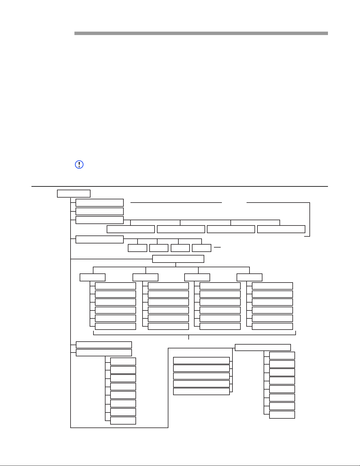
User Guide DDOC0108-000-A2
Simple Network Management Protocol
The CNS4 supports Simple Network Management Protocol (SNMP). The data provided to the
user's SNMP-configured workstation. The user may configure SNMP for a Windows workstation
via the Windows Control Panel. The user should consult with their network administrator for details
on configuration and utilization of the SNMP traps and other data capture programs. Figure 6-6
shows the OID command hierarchic. Below are examples of making use of the SNMP agent
running on the CNS4. Refer to the OID tree and the MIB for objects to query/set. Some objects are
read only, write-only, as well as read-write. In these examples, note the cnsSnmp.X.Y format. You
can correlate from these examples and the OID tree (Figure 9.1) on how to access different
objects. A majority of the objects are STRINGS and we denote that by passing an ‘s’ to the set
command.A.
Refer to SNMP MIB for the CNS4 MIB for SNMP. The MIB default path is /usr/share/snmp/mibs/
As of the date of this document, the appropriate way to start/stop the SNMP agent via command
line is:
serv –-snmp 1 – starts the snmp agent
serv –-snmp 0 – stops the snmp agent
NOTE
Traps may not be included in all installations.
Figure 9.1 OID Tree
cnsSnmp (1)
HEALTH (1)
IBIT (2)
FSM Disk Status (3)
FSM0 EEPROM (1) FSM1 EEPROM (2) FSM2 EEPROM (3) FSM3 EEPROM (4)
LED Status (4)
S0 (1) S1 (2) S2 (3) S3 (4)
Read Only
Adjust Brightness
ETH0 (1)
IP (1)
Gateway (2)
Netmask (3)
DHCP Client ID (4)
Use DHCP (5)
Apply Changes (6)
System Config (6)
Start / Stop Services (7)
CIFS (1)
NFS (2)
FTP (3)
TFTP (4)
HTTP (5)
Telnet (6)
SNMP (7)
All (8)
IP Configuration (5)
ETH1 (2) ETH2 (3) ETH3 (4)
IP (1)
Gateway (2)
Netmask (3)
DHCP Client ID (4)
Use DHCP (5)
Apply Changes (6)
IP Config
Fibre Channel ON / OFF (9)
IP (1)
Gateway (2)
Netmask (3)
DHCP Client ID (4)
Use DHCP (5)
Apply Changes (6)
System Date (10)
System Time (11)
Reboot (12)
Shutdown (13)
IP (1)
Gateway (2)
Netmask (3)
DHCP Client ID (4)
Use DHCP (5)
Apply Changes (6)
Control Boot Services (8)
CIFS (1)
NFS (2)
FTP (3)
TFTP (4)
HTTP (5)
Telnet (6)
SNMP (7)
All (8)
DDOC0108-0042
CNS4 CSfC 9 - 1 Simple Network Management Protocol
Revision 0.0
Page 81
User Guide DDOC0108-000-A2
NOTE
If a remote machine is not available to run SNMP functionality, use 127.0.0.1 as the IP.
Example 1: CWCDS-CNS-MIB::cnsHealth.0 = STRING: "[health]
snmpget -v 2c -c cns -mCWCDS-CNS-MIB [IP.Address.Here]
cnsSnmp.1.1.0
CWCDS-CNS-MIB::cnsHealth.0 = STRING: [health]
SYSTEM: Date=04/02/2015 Time=19:22:09 Firmware Ver=1.0 CNS
Ver=1.08
Power Supply Temp 1 = 34 C Temp 2 = 26 C
Main Board Temp Bot 1 = 33 C Temp Bot 2 = 28 C
Main Board Temp Top 1 = 24 C Temp Top 2 = 30 C
status=OK
|----------------------- FSM-C Status --------------------|
| | Temp 1 | 5 V | 3.3V | Fault LED | Status LED |
|------|---------|-------|-------|-----------|------------|
| FSM0 | 21 C | 4.88V | 3.29V | OFF | OFF |
| FSM1 | 27 C | 4.90V | 3.31V | OFF | OFF |
| FSM2 | 26 C | 4.91V | 3.29V | OFF | OFF |
| FSM3 | 25 C | 4.89V | 3.29V | OFF | OFF |
|---------------------------------------------------------|
ETH_0: ip=192.168.1.22 link=1000Mb/s status=OK
ETH_1: ip=192.168.2.22 link=1000Mb/s status=OK
ETH_2: ip=192.168.3.22 link=1000Mb/s status=OK
ETH_3: ip=192.168.4.22 link=1000Mb/s status=OK
|----------------------- DAR Status ----------------------|
| | Present | Zero | Yellow | Blue | Tamper | Alarm |
| | | bit | bit | bit | bit | bit |
|--------------------------------------------------------|
|DAR0 | YES | 1 | 1 | 1 | 1 | 0 |
|DAR1 | YES | 1 | 1 | 1 | 1 | 1 |
|--------------------------------------------------------|
[!health] OK
Example 2: GET IP ETH1 – cnsSnmp.5.2.1
snmpget -v 2c -c cns -mCWCDS-CNS-MIB 10.19.6.4 cnsSnmp.5.2.1.0
CWCDS-CNS-MIB::cnsIpEth1.0 = STRING: [ipconfig]
gw=0.0.0.0
IF_ETH_1: link=1000 ip=192.168.2.22 netmask=255.255.255.0
status=OK
CFG_ETH_1: prot=static ip=192.168.2.22 netmask=255.255.255.0
status=OK
[!ipconfig] OK
Example 3: SET LED DUTY CYCLE – cnsSnmp.4.1
snmpset -v 2c -c cns -mCWCDS-CNS-MIB 10.19.6.4 cnsSnmp.4.1.0 s "100"
CWCDS-CNS-MIB::cnsS0.0 = STRING: 100
Example 4: SET ETH0 IP – cnsSnmp.5.1.1
snmpset -v 2c -c cns -mCWCDS-CNS-MIB 10.19.6.4 cnsSnmp.5.1.1.0 s
192.168.1.22
CWCDS-CNS-MIB::cnsIpEth0.0 = STRING: 192.168.1.22
CNS4 CSfC 9 - 2 Simple Network Management Protocol
Revision 0.0
Page 82

User Guide DDOC0108-000-A2
9.1 SNMP MIB
CWCDS-CNS-MIB DEFINITIONS ::= BEGIN
--
-- MIB for CWCDS CNS.
-IMPORTS
MODULE-IDENTITY, MODULE-COMPLIANCE, OBJECT-TYPE, Integer32, enterprises,
NOTIFICATION-TYPE FROMSNMPv2-SMI
OBJECT-GROUP, NOTIFICATION-GROUP FROMSNMPv2-CONF;
cnsSnmp MODULE-IDENTITY
LAST-UPDATED "201510200000Z"
ORGANIZATION "www.cw controls.com"
CONTACT-INFO
"email: [email protected]"
DESCRIPTION
"MIB for CWCDS CNS4."
REVISION "201505200000Z"
DESCRIPTION
"version 1.0"
::= { enterprises 27675 }
--
-- top level structure
--
cnsFSMStatus OBJECT IDENTIFIER ::= { cnsSnmp 3 }
cnsLED OBJECT IDENTIFIER ::= { cnsSnmp 4 }
cnsIPConfig OBJECT IDENTIFIER ::= { cnsSnmp 5 }
cnsLiveServices OBJECT IDENTIFIER ::= { cnsSnmp 7 }
cnsBootServices OBJECT IDENTIFIER ::= { cnsSnmp 8 }
cnsEth0 OBJECT IDENTIFIER ::= { cnsIPConfig 1 }
cnsEth1 OBJECT IDENTIFIER ::= { cnsIPConfig 2 }
cnsEth2 OBJECT IDENTIFIER ::= { cnsIPConfig 3 }
cnsEth3 OBJECT IDENTIFIER ::= { cnsIPConfig 4 }
--
-- Values
--
cnsHealth OBJECT-TYPE
SYNTAX OCTET STRING (SIZE (1..4096))
MAX-ACCESS read-only
STATUS current
DESCRIPTION
"Output of command: health"
::= { cnsSnmp 1 }
cnsIBIT OBJECT-TYPE
SYNTAX OCTET STRING (SIZE (1..4096))
MAX-ACCESS read-only
STATUS current
DESCRIPTION
"Output of command: ibit"
::= { cnsSnmp 2 }
CNS4 CSfC 9 - 3 Simple Network Management Protocol
Revision 0.0
Page 83

User Guide DDOC0108-000-A2
cnsSystemConfig OBJECT-TYPE
SYNTAX OCTET STRING (SIZE (1..4096))
MAX-ACCESS read-write
STATUS current
DESCRIPTION
"Object that is used to display current system configuration."
DEFVAL { "" }
::= { cnsSnmp 6 }
cnsFibreChannel OBJECT-TYPE
SYNTAX OCTET STRING (SIZE (1..4096))
MAX-ACCESS read-write
STATUS current
DESCRIPTION
"Object that is used to start and stop fibre channel service."
DEFVAL { "" }
::= { cnsSnmp 9 }
cnsSystemDate OBJECT-TYPE
SYNTAX OCTET STRING (SIZE (1..4096))
MAX-ACCESS read-write
STATUS current
DESCRIPTION
"Object that is used to set and get the system date."
DEFVAL { "" }
::= { cnsSnmp 10 }
cnsSystemTime OBJECT-TYPE
SYNTAX OCTET STRING (SIZE (1..4096))
MAX-ACCESS read-write
STATUS current
DESCRIPTION
"Object that is used to set and get the system time."
DEFVAL { "" }
::= { cnsSnmp 11 }
cnsReboot OBJECT-TYPE
SYNTAX INTEGER
MAX-ACCESS read-write
STATUS current
DESCRIPTION
"Object that is used to reboot."
DEFVAL { "" }
::= { cnsSnmp 12 }
cnsShutdow n OBJECT-TYPE
SYNTAX INTEGER
MAX-ACCESS read-write
STATUS current
DESCRIPTION
"Object that is used to reboot."
DEFVAL { "" }
::= { cnsSnmp 13 }
cnsFSMDiskStatus OBJECT-TYPE
SYNTAX OCTET STRING (SIZE (1..4096))
MAX-ACCESS read-only
STATUS current
DESCRIPTION
"Output of command: fsmdiskstatus"
::= { cnsSnmp 3 }
CNS4 CSfC 9 - 4 Simple Network Management Protocol
Revision 0.0
Page 84

User Guide DDOC0108-000-A2
cnsFSM0EEPROMOBJECT-TYPE
SYNTAX OCTET STRING (SIZE (1..4096))
MAX-ACCESS read-only
STATUS current
DESCRIPTION
"Output of command: Contents of FSM0 EEPROM"
::= { cnsFSMDiskStatus 1 }
cnsFSM1EEPROMOBJECT-TYPE
SYNTAX OCTET STRING (SIZE (1..4096))
MAX-ACCESS read-only
STATUS current
DESCRIPTION
"Output of command: Contents of FSM1 EEPROM"
::= { cnsFSMDiskStatus 2 }
cnsFSM2EEPROMOBJECT-TYPE
SYNTAX OCTET STRING (SIZE (1..4096))
MAX-ACCESS read-only
STATUS current
DESCRIPTION
"Output of command: Contents of FSM2 EEPROM"
::= { cnsFSMDiskStatus 3 }
cnsFSM3EEPROMOBJECT-TYPE
SYNTAX OCTET STRING (SIZE (1..4096))
MAX-ACCESS read-only
STATUS current
DESCRIPTION
"Output of command: Contents of FSM3 EEPROM"
::= { cnsFSMDiskStatus 4 }
--
-- LED Objects
--
cnsS0 OBJECT-TYPE
SYNTAX OCTET STRING (SIZE (1..4096))
MAX-ACCESS read-write
STATUS current
DESCRIPTION
"Read LED status. Set S0 duty cycle."
DEFVAL { "" }
::= { cnsLED 1 }
cnsS1 OBJECT-TYPE
SYNTAX OCTET STRING (SIZE (1..4096))
MAX-ACCESS read-write
STATUS current
DESCRIPTION
"Read LED status. Set S1 duty cycle."
DEFVAL { "" }
::= { cnsLED 2 }
CNS4 CSfC 9 - 5 Simple Network Management Protocol
Revision 0.0
Page 85

User Guide DDOC0108-000-A2
cnsS2 OBJECT-TYPE
SYNTAX OCTET STRING (SIZE(1..4096))
MAX-ACCESS read-write
STATUS current
DESCRIPTION
"Read LED status. Set S2 duty cycle."
DEFVAL { "" }
::= { cnsLED 3 }
cnsS3 OBJECT-TYPE
SYNTAX OCTET STRING (SIZE (1..4096))
MAX-ACCESS read-write
STATUS current
DESCRIPTION
"Read LED status. Set S3 duty cycle."
DEFVAL { "" }
::= { cnsLED 4 }
--
-- ETH0 ITEMS
--
cnsIpEth0 OBJECT-TYPE
SYNTAX OCTET STRING (SIZE (1..4096))
MAX-ACCESS read-write
STATUS current
DESCRIPTION
"Read eth0 status. Set eth0 IP."
DEFVAL { "" }
::= { cnsEth0 1 }
cnsGatew ayEth0 OBJECT-TYPE
SYNTAX OCTET STRING (SIZE(1..4096))
MAX-ACCESS read-write
STATUS current
DESCRIPTION
"Read eth0 status. Set eth0 gateway."
DEFVAL { "" }
::= { cnsEth0 2 }
cnsNetmaskEth0 OBJECT-TYPE
SYNTAX OCTET STRING (SIZE (1..4096))
MAX-ACCESS read-write
STATUS current
DESCRIPTION
"Read eth0 status. Set eth0 netmask."
DEFVAL { "" }
::= { cnsEth0 3 }
cnsDhcpClientIdEth0 OBJECT-TYPE
SYNTAX OCTET STRING (SIZE (1..4096))
MAX-ACCESS read-write
STATUS current
DESCRIPTION
"Read eth0 status. Set eth0 DHCPClient ID."
DEFVAL { "" }
::= { cnsEth0 4 }
CNS4 CSfC 9 - 6 Simple Network Management Protocol
Revision 0.0
Page 86

User Guide DDOC0108-000-A2
cnsUseDhcpEth0 OBJECT-TYPE
SYNTAX OCTET STRING (SIZE (1..4096))
MAX-ACCESS read-write
STATUS current
"Read eth0 status. Enable/Disable DHCP for eth0."
DEFVAL { "" }
::= { cnsEth0 5 }
cnsApplyChangesEth0 OBJECT-TYPE
SYNTAX OCTET STRING (SIZE (1..4096))
MAX-ACCESS read-write
STATUS current
DESCRIPTION
"Write-only; Reading will return eth0 status. Apply changes made to eth0."
DEFVAL { "" }
::= { cnsEth0 6 }
--
-- ETH1 ITEMS
--
cnsIpEth1 OBJECT-TYPE
SYNTAX OCTET STRING (SIZE (1..4096))
MAX-ACCESS read-write
STATUS current
DESCRIPTION
"Read eth1 status. Set eth1 IP."
DEFVAL { "" }
::= { cnsEth1 1 }
cnsGatew ayEth1 OBJECT-TYPE
SYNTAX OCTET STRING (SIZE (1..4096))
MAX-ACCESS read-write
STATUS current
DESCRIPTION
"Read eth1 status. Set eth1 gateway."
DEFVAL { "" }
::= { cnsEth1 2 }
cnsNetmaskEth1 OBJECT-TYPE
SYNTAX OCTET STRING (SIZE (1..4096))
MAX-ACCESS read-write
STATUS current
DESCRIPTION
"Read eth1 status. Set eth1 netmask."
DEFVAL { "" }
::= { cnsEth1 3 }
cnsDhcpClientIdEth1 OBJECT-TYPE
SYNTAX OCTET STRING (SIZE (1..4096))
MAX-ACCESS read-write
STATUS current
DESCRIPTION
"Read eth1 status. Set eth1 DHCP Client ID."
DEFVAL { "" }
::= { cnsEth1 4 }
CNS4 CSfC 9 - 7 Simple Network Management Protocol
Revision 0.0
Page 87

User Guide DDOC0108-000-A2
cnsUseDhcpEth1 OBJECT-TYPE
SYNTAX OCTET STRING (SIZE (1..4096))
MAX-ACCESS read-write
STATUS current
DESCRIPTION
"Read eth1 status. Enable/Disable DHCP for eth1."
DEFVAL { "" }
::= { cnsEth1 5 }
cnsApplyChangesEth1 OBJECT-TYPE
SYNTAX OCTET STRING (SIZE (1..4096))
MAX-ACCESS read-write
STATUS current
DESCRIPTION
"Write-only; Reading will return eth1 status. Apply changes made to eth1."
DEFVAL { "" }
::= { cnsEth1 6 }
--
-- ETH2 ITEMS
--
cnsIpEth2 OBJECT-TYPE
SYNTAX OCTET STRING (SIZE (1..4096))
MAX-ACCESS read-write
STATUS current
DESCRIPTION
"Read eth2 status. Set eth2 IP."
DEFVAL { "" }
::= { cnsEth2 1 }
cnsGatew ayEth2 OBJECT-TYPE
SYNTAX OCTET STRING (SIZE (1..4096))
MAX-ACCESS read-write
STATUS current
DESCRIPTION
"Read eth2 status. Set eth2 gateway."
DEFVAL { "" }
::= { cnsEth2 2 }
cnsNetmaskEth2 OBJECT-TYPE
SYNTAX OCTET STRING (SIZE (1..4096))
MAX-ACCESS read-write
STATUS current
DESCRIPTION
"Read eth2 status. Set eth2 netmask."
DEFVAL { "" }
::= { cnsEth2 3 }
cnsDhcpClientIdEth2 OBJECT-TYPE
SYNTAX OCTET STRING (SIZE (1..4096))
MAX-ACCESS read-write
STATUS current
DESCRIPTION
"Read eth2 status. Set eth2 DHCP Client ID."
DEFVAL { "" }
::= { cnsEth2 4 }
CNS4 CSfC 9 - 8 Simple Network Management Protocol
Revision 0.0
Page 88

User Guide DDOC0108-000-A2
cnsUseDhcpEth2 OBJECT-TYPE
SYNTAX OCTET STRING (SIZE (1..4096))
MAX-ACCESS read-write
STATUS current
DESCRIPTION
"Read eth2 status. Enable/Disable DHCP for eth2."
DEFVAL { "" }
::= { cnsEth2 5 }
cnsApplyChangesEth2 OBJECT-TYPE
SYNTAX OCTET STRING (SIZE (1..4096))
MAX-ACCESS read-write
STATUS current
DESCRIPTION
"Write-only; Reading will return eth2 status. Apply changes made to eth2."
DEFVAL { "" }
::= { cnsEth2 6 }
--
-- ETH3 ITEMS
--
cnsIpEth3 OBJECT-TYPE
SYNTAX OCTET STRING (SIZE (1..4096))
MAX-ACCESS read-write
STATUS current
DESCRIPTION
"Read eth3 status. Set eth3 IP."
DEFVAL { "" }
::= { cnsEth3 1 }
cnsGatew ayEth3 OBJECT-TYPE
SYNTAX OCTET STRING (SIZE (1..4096))
MAX-ACCESS read-write
STATUS current
DESCRIPTION
"Read eth3 status. Set eth3 gateway."
DEFVAL { "" }
::= { cnsEth3 2 }
cnsNetmaskEth3 OBJECT-TYPE
SYNTAX OCTET STRING (SIZE (1..4096))
MAX-ACCESS read-write
STATUS current
DESCRIPTION
"Read eth3 status. Set eth3 netmask."
DEFVAL { "" }
::= { cnsEth3 3 }
cnsDhcpClientIdEth3 OBJECT-TYPE
SYNTAX OCTET STRING (SIZE (1..4096))
MAX-ACCESS read-write
STATUS current
DESCRIPTION
"Read eth3 status. Set eth3 DHCP Client ID."
DEFVAL { "" }
::= { cnsEth3 4 }
CNS4 CSfC 9 - 9 Simple Network Management Protocol
Revision 0.0
Page 89

User Guide DDOC0108-000-A2
cnsUseDhcpEth3 OBJECT-TYPE
SYNTAX OCTET STRING (SIZE (1..4096))
MAX-ACCESS read-write
STATUS current
DESCRIPTION
"Read eth3 status. Enable/Disable DHCP for eth3."
DEFVAL { "" }
::= { cnsEth3 5 }
cnsApplyChangesEth3 OBJECT-TYPE
SYNTAX OCTET STRING (SIZE (1..4096))
MAX-ACCESS read-write
STATUS current
DESCRIPTION
"Write-only; Reading w ill return eth3 status. Apply changes made to eth3."
DEFVAL { "" }
::= { cnsEth3 6 }
--
-- CONTROL LIVESERVICES OBJECTS
--
cnsCifsLive OBJECT-TYPE
SYNTAX OCTET STRING (SIZE (1..4096))
MAX-ACCESS read-write
STATUS current
DESCRIPTION
"Used to start (1) and stop (0) the CIFS server."
DEFVAL { "" }
::= { cnsLiveServices 1 }
cnsNfsLive OBJECT-TYPE
SYNTAX OCTET STRING (SIZE (1..4096))
MAX-ACCESS read-write
STATUS current
DESCRIPTION
"Used to start (1) and stop (0) the NFS server."
DEFVAL { "" }
::= { cnsLiveServices 2 }
cnsFtpLive OBJECT-TYPE
SYNTAX OCTET STRING (SIZE (1..4096))
MAX-ACCESS read-write
STATUS current
DESCRIPTION
"Used to start (1) and stop (0) the FTP server."
DEFVAL { "" }
::= { cnsLiveServices 3 }
cnsTftpLive OBJECT-TYPE
SYNTAX OCTET STRING (SIZE (1..4096))
MAX-ACCESS read-write
STATUS current
DESCRIPTION
"Used to start (1) and stop (0) the TFTP server."
DEFVAL { "" }
::= { cnsLiveServices 4 }
CNS4 CSfC 9 - 10 Simple Network Management Protocol
Revision 0.0
Page 90

User Guide DDOC0108-000-A2
cnsHttpLive OBJECT-TYPE
SYNTAX OCTET STRING (SIZE (1..4096))
MAX-ACCESS read-write
STATUS current
DESCRIPTION
"Used to start (1) and stop (0) the HTTP server."
DEFVAL { "" }
::= { cnsLiveServices 5 }
cnsTelnetLive OBJECT-TYPE
SYNTAX OCTET STRING (SIZE (1..4096))
MAX-ACCESS read-write
STATUS current
DESCRIPTION
"Used to start (1) and stop (0) the Telnet server."
DEFVAL { "" }
::= { cnsLiveServices 6 }
cnsSnmpLive OBJECT-TYPE
SYNTAX OCTET STRING (SIZE (1..4096))
MAX-ACCESS read-write
STATUS current
DESCRIPTION
"Used to ONLY stop (0) SNMP."
DEFVAL { "" }
::= { cnsLiveServices 7 }
cnsAllLive OBJECT-TYPE
SYNTAX OCTET STRING (SIZE (1..4096))
MAX-ACCESS read-write
STATUS current
DESCRIPTION
"Used to start (1) and stop (0) all the services EXCEPT SNMP."
DEFVAL { "" }
::= { cnsLiveServices 8 }
--
-- CONTROL BOOT SERVICES OBJECTS
--
cnsCifsBoot OBJECT-TYPE
SYNTAX OCTET STRING (SIZE (1..4096))
MAX-ACCESS read-write
STATUS current
DESCRIPTION
"Used to start (1) and stop (0) the CIFS server on boot."
DEFVAL { "" }
::= { cnsBootServices 1 }
cnsNfsBoot OBJECT-TYPE
SYNTAX OCTET STRING (SIZE (1..4096))
MAX-ACCESS read-write
STATUS current
DESCRIPTION
"Used to start (1) and stop (0) the NFS server on boot."
DEFVAL { "" }
::= { cnsBootServices 2 }
CNS4 CSfC 9 - 11 Simple Network Management Protocol
Revision 0.0
Page 91

User Guide DDOC0108-000-A2
cnsFtpBoot OBJECT-TYPE
SYNTAX OCTET STRING (SIZE (1..4096))
MAX-ACCESS read-write
STATUS current
DESCRIPTION
"Used to start (1) and stop (0) the FTP server on boot."
DEFVAL { "" }
::= { cnsBootServices 3 }
cnsTftpBoot OBJECT-TYPE
SYNTAX OCTET STRING (SIZE (1..4096))
MAX-ACCESS read-write
STATUS current
DESCRIPTION
"Used to start (1) and stop (0) the TFTP server on boot."
DEFVAL { "" }
::= { cnsBootServices 4 }
cnsHttpBoot OBJECT-TYPE
SYNTAX OCTET STRING (SIZE (1..4096))
MAX-ACCESS read-write
STATUS current
DESCRIPTION
"Used to start (1) and stop (0) the HTTP server on boot."
DEFVAL { "" }
::= { cnsBootServices 5 }
cnsTelnetBoot OBJECT-TYPE
SYNTAX OCTET STRING (SIZE (1..4096))
MAX-ACCESS read-write
STATUS current
DESCRIPTION
"Used to start (1) and stop (0) the Telnet server on boot."
DEFVAL { "" }
::= { cnsBootServices 6 }
cnsSnmpBoot OBJECT-TYPE
SYNTAX OCTET STRING (SIZE (1..4096))
MAX-ACCESS read-write
STATUS current
DESCRIPTION
"Used to start (1) and stop (0) SNMP on boot."
DEFVAL { "" }
::= { cnsBootServices 7 }
cnsAllBoot OBJECT-TYPE
SYNTAX OCTET STRING (SIZE (1..4096))
MAX-ACCESS read-write
STATUS current
DESCRIPTION
"Used to start (1) and stop (0) all the services on boot."
DEFVAL { "" }
::= { cnsBootServices 8 }
END
CNS4 CSfC 9 - 12 Simple Network Management Protocol
Revision 0.0
Page 92
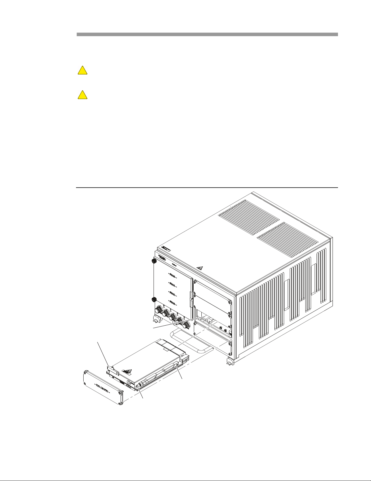
User Guide DDOC0108-000-A2
Remove / Replace
10.1 ILE Module - Install / Remove
CAUTION
EQUIPMENT DAMAGE. Do not remove / install an ILE module with power applied or damage to
the ILE module and / or CNS4 will occur.
CAUTION
EQUIPMENT DAMAGE. Exercise ESD precautions when installing, removing, or handling the ILE
module. Failure to properly handle ILE modules can result in damage
10.1.1 Remove
1. If applicable, turn 28VDC power supply OFF.
2. Remove four screws and FIPS CRYPTO cover panel.
3. Loosen two Allen screws (Figure 10.1) to release wedgelocks.
4. Grasp eject lever and carefully pull ILE module from the CHS4 chassis.
5. Place ILE module in a static-safe container and close cover.
Figure 10.1 ILE Module Replacement
Eject
Lever
Slide
DDOC0108-0004
Rail
Allen Screw
10.1.2 Install
1. Remove ILE module from static safe container.
2. Align ILE module rails with the chassis slides and carefully push module into chassis. Ensure
module connector fully seats in ILE backplane connector.
CNS4 CSfC 10 - 1 Remove / Replace
Revision 2.0
Page 93
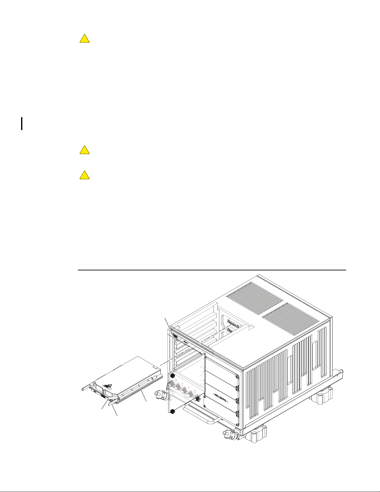
User Guide DDOC0108-000-A2
CAUTION
IMPROPER OPERATION, Wedgelock levers must be raised to ensure conductive cooling of ILE
module occurs. Failure to close levers tightly may result in improper operation.
3. Tighten two Allen screws to raise wedgelocks and secure ILE module in place. Tighten screws
to 8.0 in.-lb (0.9 Nm).
4. Clean FIPS CRYPTO cover panel screws with primer (Loctite 7649) to remove old threadlock.
5. Coat screw threads with threadlock (Loctite 222).
6. Place FIPS CRYPTO cover panel onCNS4 chassis and secure with four screws. Tighten
screws to 8.0 in.-lb (0.9 Nm).
7. Install CNS4 anti-tamper label. Refer to paragraph 4.2 Inspection for label location. Refer to
Ordering Information section for tamper label information.
10.2 FSM-C Module - Install / Remove
CAUTION
EQUIPMENT DAMAGE. Do not remove / install a FSM-C module with power applied or damage to
the FSM-C module and / or CNS4 will occur.
CAUTION
EQUIPMENT DAMAGE. Exercise ESD precautions when installing, removing, or handling the
FSM-C module. Failure to properly handle FSM-C modules can result in damage
10.2.1 Remove
1. If applicable, turn 28VDC power supply OFF.
2. Loosen two captive screws and open FSM cover panel.
3. Extend / pull wedgelock levers (Figure 10.2) away from module body to release wedgelocks.
4. Grasp eject lever and carefully pull FSM-C module from CNS4 chassis.
5. Place FSM-C module in a static-safe container and close cover.
Figure 10.2 FSM-C Module Replacement
Slide
Rail
Eject
Lever
CNS4 CSfC 10 - 2 Remove / Replace
Wedgelock Lever
DDOC0108-0008
Revision 2.0
Page 94
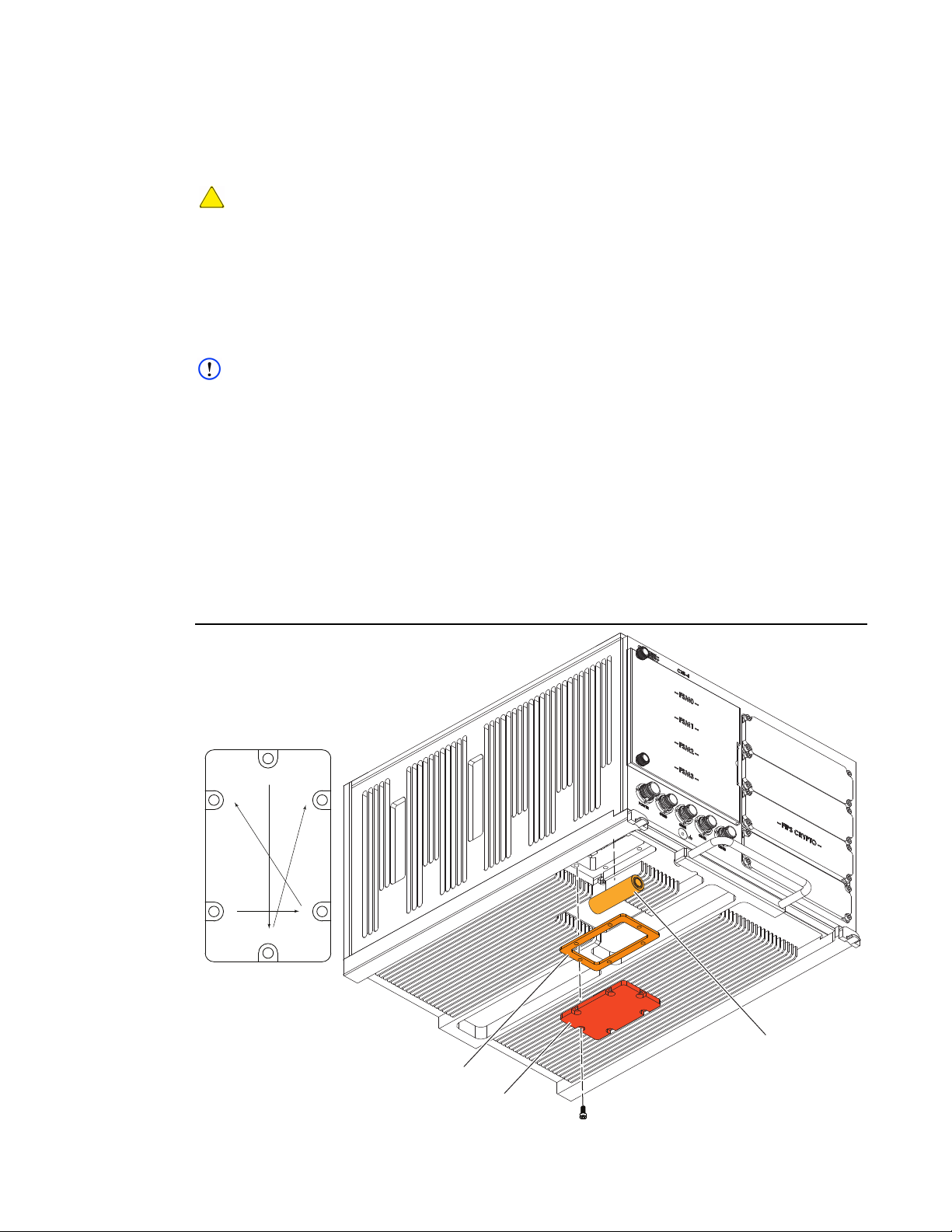
User Guide DDOC0108-000-A2
DDOC0108-0031
Battery Cover
Battery
1
2
45
63
Gasket
(+)
(-)
Tightening Sequence
10.2.2 Install
1. Remove FSM-C module from static safe container.
2. Align FSM-C module rails with chassis slides and carefully push module into chassis. Ensure
module connector fully seats in storage backplane connector.
CAUTION
IMPROPER OPERATION, Wedgelock levers must be closed to ensure conductive cooling of
FSM-C module occurs. Failure to close levers tightly may result in improper operation.
3. Place wedgelock levers in the closed / retracted position to raise wedgelocks and secure
module in place.
4. Close FSM cover panel and secure with two captive screws. Tighten screws finger-tight.
10.3 Chassis Battery Replacement
NOTE
The battery should be replaced every five years. Refer to Ordering Information section for part
number information.
10.3.1 Remove
1. If applicable, turn 28VDC power supply OFF.
2. Disconnect cables and remove CNS4 from mounting surface / tray. Refer to paragraph 4.4
CNS4 Install / Remove for additional information.
3. Remove six screws, battery cover, and gasket from CNS4 chassis (Figure 4-7).
4. Remove battery from battery holder.
5. Discard battery.
Figure 10.3 Chassis Battery Replacement
CNS4 CSfC 10 - 3 Remove / Replace
Revision 2.0
Page 95
User Guide DDOC0108-000-A2
10.3.2 Install
1. Place battery in battery holder. Ensure battery polarity is correct (positive towards front of unit).
2. Clean screws with primer (Loctite 7649) to remove old threadlock.
3. Coat screw threads with threadlock (Loctite 222).
4. Place gasket and battery cover on CNS4 chassis and align mounting holes.
5. Use six screws to secure battery cover in place. Tighten screws to 8.0 in-lb (0.9 Nm) using
pattern shown in Figure 10.3.
6. Install new chassis battery label over old label. Refer to Ordering Information section for part
number information.
NOTE
Install and replacement dates should use MM / YYYY format.
7. Use a permanent marker to write Install and Replacement dates on label.
8. Install CNS4 on mounting surface / tray and connect cables. Refer to paragraph 4.4 CNS4
Install / Remove for additional information.
10.4 ILE Module Battery Replacement
CAUTION
EQUIPMENT DAMAGE. Exercise ESD precautions when installing, removing, or handling the ILE
module. Failure to properly handle ILE modules can result in damage
NOTE
The batteries should be replaced every five years. Refer to Ordering Information section for part
number information.
NOTE
Replacement of the batteries will require breaking ILE tamper seal.
NOTE
The ILE module contains two batteries. They should be replaced as a pair.
10.4.1 Remove
1. If applicable, turn 28VDC power supply OFF.
2. Remove ILE module from CNS4 chassis. Refer to paragraph 10.1 ILE Module - Install /
Remove for additional information.
3. Remove ILE tamper label.
4. Remove 10 screws and cover from ILE chassis (Figure 10.4).
5. Remove batteries from battery holders.
6. Discard batteries.
10.4.2 Install
1. Place batteries in battery holder.
2. Place cover on ILE chassis and align mounting holes.
3. Clean screws with primer (Loctite 7649) to remove old threadlock.
4. Coat screw threads with threadlock (Loctite 222).
5. Use 10 screws to secure battery cover in place. Tighten screws to 8.0 in-lb (0.9 Nm) using
pattern shown in Figure 4-8.
6. Install ILE tamper label. Refer to paragraph 4.2 Inspection for label locations. Refer to
Ordering Information section for tamper label information.
CNS4 CSfC 10 - 4 Remove / Replace
Revision 2.0
Page 96
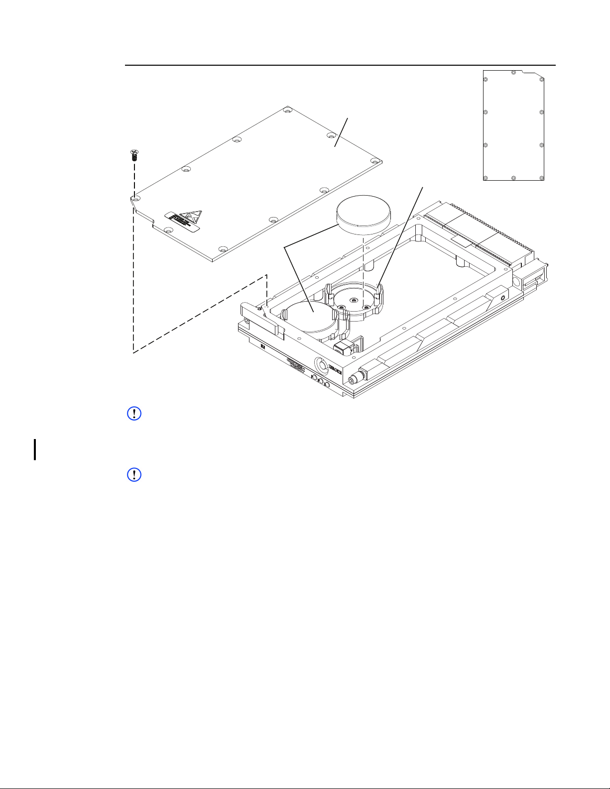
User Guide DDOC0108-000-A2
DDOC0108-0040
Cover
Battery
Battery Holder
9
17
8
6
4
5
3
10
2
Tighten
Pattern
Figure 10.4 ILE Module Battery Replacement
NOTE
ILE Battery Label is located on CNS4 chassis.
7. Install new ILE battery label over old label. Refer to Ordering Information section for part
number information.
NOTE
Install and replacement dates should use MM / YYYY format.
8. Use a permanent marker to write Install and Replacement dates on label.
9. Install ILE module in CNS4. Refer to paragraph 10.1 ILE Module - Install / Remove for
additional information.
CNS4 CSfC 10 - 5 Remove / Replace
Revision 2.0
Page 97

User Guide DDOC0108-000-A2
Command Line Interface
The Command Line Interface (CLI) is the primary method of communicating with and configuring
the CNS4.
11.1 CLI Commands
11.1.1 CNS4 Commands
dhcpconfig.............................Configures DHCP services.
fupdate ................................... Used to perform field update of CNS4.
health...................................... Shows health information for CNS4.
help.........................................Shows list of available help topics.
ibit...........................................Starts CNS4 initiated built-in test.
ipconfig .................................. Sets / shows IP interface information.
istarget ................................... Starts / stops and report iSCSI target server.
ledctrl .....................................Sets / shows CNS4 front panel LED duty cycle.
log...........................................Shows / clears CNS4 log files.
password ...............................Sets / shows password.
reboot ..................................... Stops all services, unmounts storage, and does a soft reboot.
serial_config .......................... Sets / shows serial port configuration or gets current configuration.
serv.........................................Sets boot configuration and manually starts / stops CNS4 services.
shutdown ............................... Stops all services, unmounts storage, and halts CNS4 operating
system.
swcrypt................................... Sets / shows disk encryption options.
sysconfig ...............................Sets / shows CNS4 disk and system storage.
sysdate...................................Sets / shows CNS4 time and date.
11.1.2 FSM-C Module Commands
diskcfg.................................... Shows information about FSM-C module disk / interface.
fsmpurge................................ Removes all data from FSM-C module.
fsmdiskstatus ........................ Shows FSM-C module NAS partition status and usage.
11.1.3 ILE Commands
cm_create_account............... Set / show user name and password. Also specifies DEK source
and storage location.
cm_crypto .............................. Utility used to perform HMAC-SHA256 generation and AES-256
key wrap / unwrap.
cm_field_update....................Used to perform field update of ILE.
cm_key ................................... Sets / shows encryption key management (key creation, usage,
encryption).
cm_log.................................... Shows / clears ILE log files.
cm_login ................................ Allows users to login / use ILE.
cm_state................................. Shows current user / encryption key information.
11.2 Commands
CNS4 CSfC 11 - 1 Command Line Interface
Revision 0.0
Page 98
User Guide DDOC0108-000-A2
11.2.1 cm_create_account
Syntax:
cm_create_account [ -h | --help ] | [ -v | --version ]
cm_create_account [ -u <str> ] [ -p <str> ] [ -m i | e ] [ -k e | s | n ]
cm_create_account [ -u <str> ] [ -p <str> ]
Description:
The cm_create_account command provides the user the ability to create accounts. The first
account created will always be the crypto officer account and every other account created
thereafter will be treated as users. The crypto officer must be logged in to create user accounts.
Normal user accounts only have certain privileges where they are not able to choose the DEK nor
where the DEK is stored. Every user shares the same DEK as the crypto officer.
Options:
-h, --help............................. Help
-v, --version ........................ Show version information
-u <string> .......................... Specify username
-p <string> .......................... Specify password (min. 8 characters; max. 64 characters)
-m <char>........................... ILE Key Generation Mode. i=Internal, e=External
-k <char> ............................ ILE Key Storage Location. e=EEPROM, s=SRAM, n=NONE
Example 1. Create a crypto officer account with username john, password aBcDeFg1, with internal key generation
stored on the SRAM
cns> cm_create_account -u john -p aBcDeFg1 -m i -k s
[cm_create_account]
user_token=0xab491feccdd158654adab4bb10ddfffe3948571fddeee43f6b7c9a0cc0013693
token_hmac=0xce6256b4220638eefb3bb3c428ddd853353bc9ce3f436062ab59d9fcd9f93642
status=OK
[!cm_create_Account]
Example 2. Create a crypto officer account with username john, password aBcDeFg1, with external key
generation stored on the EEPROM
cns> cm_create_account -u john -p aBcDeFg1 -m e -k e
[cm_create_account]
user_token=0xc9ed6c3bbc3de43110d4e5b67da39ea4d1d79d1fb269d25759b38a25db0a8552c72
158ebc19e7e60
token_hmac=0x8ba8729d3a22bc6787b404a13f7cbec190ce5f64fc0e770c8710f60318274259
status=OK
[!cm_create_account]
Example 3. Create a user account with username marty, password gHpErCf7
cns> cm_create_account -u marty -p gHpErCf7
[cm_create_account]
user_token=0xa77650375de646873a61d4c18954d2c4aaf35cd2af59bd9f0646b5a55223011a
token_hmac=0xbd7147c5119728ffea5aa2d517c3c747242ab8ad2e3259561a59d9dbe8e43248
status=OK
[!cm_create_account]
CNS4 CSfC 11 - 2 Command Line Interface
Revision 0.0
Page 99

User Guide DDOC0108-000-A2
11.2.2 cm_crypto
Syntax:
cm_crypto [ -h | --help ] | [ -v | --version ]
cm_crypto [ -p <hex> | --plaintext <hex>] & [ -k <hex> | --key <hex> ]
cm_crypto [ -c <hex> | --ciphertext <hex> ] & [ -k <hex> | --key <hex> ]
cm_crypto [ -t <hex> | --text <hex> ] & [ -k <hex> | --key <hex> ]
Description:
The cm_crypto command provides the user the ability to perform cryptographic operations on data
of their choosing. More specifically the user may use this utility to decrypt KEKs, encrypt DEKS,
and generate HMAC-SHA256s.
Options:
-h, --help.............................. Help
-v, --version ......................... Show version information
-p, --plaintext <hex> ............ Data to be used to perform AES256 Keywrap on. Must be a 32 byte
value represented by 64 hex characters
-c, --ciphertext <hex> .......... Data to be used to perform AES256 KeyUnwrap on. Must be a 40
byte value represented by 80 hex characters
-t, --text <hex>..................... Data to be used when calculating HMAC-SHA-256. Must be less than
a 64 byte value represented by 128 hex characters
.-k, --key <hex> ................... Key to be used against AES256 Keywrap / KeyUnwrap and HMAC-
SHA-256. Must be a 32 byte value represented by 64 hex characters
Example 1. Perform AES256 KeyUnWrap
cns> cm_crypto -c
aa6db2ebee5438665f49d4b228942a2a53b78552b7f16be37c77508b596bdc5998e5ba844947227f -k
0000000000000000000000000000000000000000000000000000000000001234
[cm_crypto]
ciphertext=0xaa6db2ebee5438665f49d4b228942a2a53b78552b7f16be37c77508b596bdc5998e
5ba844947227f
Key=0x0000000000000000000000000000000000000000000000000000000000001234
keyunwrap_output=0xb68dc04ac3ade0e9f883eded13a9a90e7b86d7b6a4c22c4d26b7344e8ce2e
f9b
[!cm_crypto]
Example 2. Perform AES256 KeyWrap
cns> cm_crypto -p c213a1e6d0cc9f61d2e7777d0c1a3b5cb70a3342e70252ae0773cb326cf17da9 -
k 0c56d2e4fa740fcf92119502f8ca88378190dbfb63c545909a26d478c6f595d0
[cm_crypto]
plaintext=c213a1e6d0cc9f61d2e7777d0c1a3b5cb70a3342e70252ae0773cb326cf17da9
key=0c56d2e4fa740fcf92119502f8ca88378190dbfb63c545909a26d478c6f595d0
keywrap_output=0xe9ed6d1cd711600f8c7f8eea6f22d9199bf85698b86ac2a5f6bf3a8c5e5359a7b9c79b4d3a1
bb39e
[!cm_crypto]
CNS4 CSfC 11 - 3 Command Line Interface
Revision 0.0
Page 100
User Guide DDOC0108-000-A2
11.2.3 cm_field_update
Syntax:
cm_field_update [ -h | --help ] | [ -v | --version ]
cm_field_update [ -f <str> ] [ -s <str> ]
Description:
The cm_field_update command provides the user the ability to update the firmware within the ILE
module. The update is a trusted update that requires an update file paired with a signature. This
update file and signature will be verified during the transfer and will generate a failure if verification
is unsuccessful.
NOTE
The update files must be placed on the root of fsm_nas0 on the CNS4.Refer to paragraph 6.3.2
ILE Module Firmware for more details.
NOTE
Curtiss-Wright will be the only entity who provides ILE firmware updates.
Options:
-h, --help.............................. Help
-v, --version ......................... Show version information
-f .......................................... Filename (ex. file.bin)
-s ......................................... Signature (ex. signature.bin)
Example 1. Performing an update with official files supplied by Curtiss-Wright
cns> cm_field_update -f ileTestImage.bin -s ileTestImageSignature.bin
[cm_field_update]
STATUS: Activity
[...............................................................................
....................................................................] Update
Complete. Please wait 5 seconds to power cycle the unit.
status=OK
[!cm_field_update]
Example 2. Performing an update with an invalid update file and a valid signature
cns> cm_field_update -f ileTestImageInvalid.bin -s ileTestImageSignature.bin
[cm_field_update]
STATUS: Activity
[...............................................................................
........................................................................(0x3005)
:[FUPDATE] - verification failed
[!cm_field_update]
CNS4 CSfC 11 - 4 Command Line Interface
Revision 0.0
 Loading...