

Curtis TLP10, TLP15, TLP20, TLP30, TLP61 Installation Instructions, Service & Warranty Information
Page 1
FIND OUT MORE
ON
THE WEB.
WILBURCURTIS.COM
Installation Instructions,
Service & Warranty Information
Revised: April 2002
Models Included
••
• TLP10
••
••
• TLP15
••
••
• TLP20
••
••
• TLP30*
••
••
• TLP61
••
* NOT UL LISTED
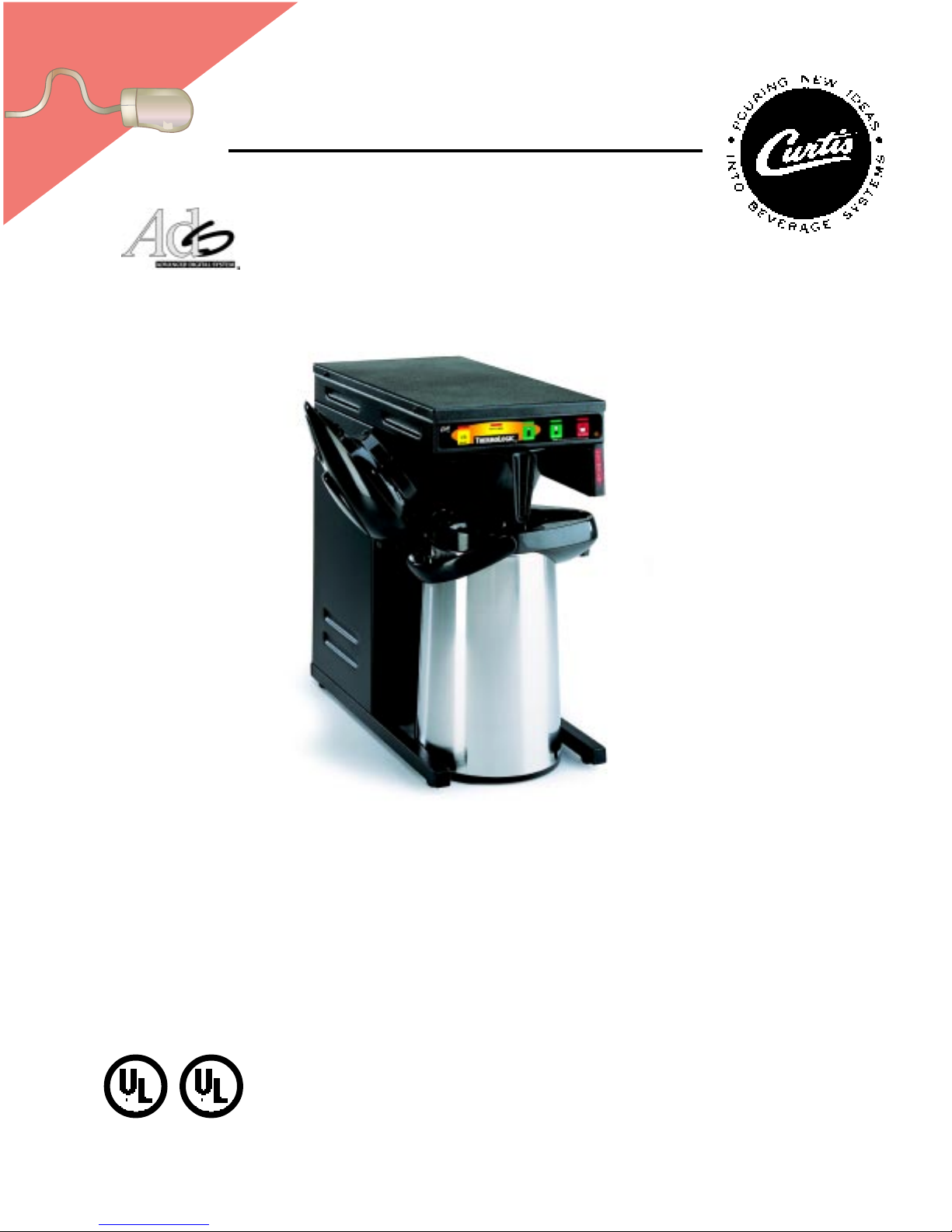
DIGIT AL AIRPOT BREWING SYSTEM
WILBUR CURTIS COMPANY Montebello, CA 90640
C
ISO 9001 REGISTERED
FOR THE LATEST SPEC INFORMATION GO TO WWW.WILBURCURTIS.COM
TLP
DRAFT COPY
Not Released. This Version Exists as File No.
I:\DIAGRAMS\FRANK\FX-134.p65
•
Page 2

FF
F
FF
ONON
ON
ONON
WILBURCURTIS.COMWILBURCURTIS.COM
WILBURCURTIS.COM
WILBURCURTIS.COMWILBURCURTIS.COM
INDIND
IND
INDIND
THETHE
THE
THETHE
OUTOUT
OUT
OUTOUT
WEBWEB
WEB
WEBWEB
MOREMORE
MORE
MOREMORE
..
.
..
Revised: Mar, 2002
MODELS INCLUDEDMODELS INCLUDED
MODELS INCLUDED
MODELS INCLUDEDMODELS INCLUDED
••
• TLP10
••
••
• TLP15
••
••
• TLP20
••
••
• TLP30*
••
••
• TLP61
••
* NOT UL LISTED
CAUTION: Please use
this setup procedure
before attempting to use
this brewer. Failure to follow the
instructions can result in injury
or the voiding of the warranty.
CAUTION: DO NOT
connect this brewer to
hot water. The inlet
valve is not rated for hot water.
IMPORTANT: This
equipment is to be
installed to comply with
the applicable federal, state, or
local plumbing and electrical
codes having jurisdiction.
WARNING: To avoid
scalding, do NOT
remove brew cone
while brew indicator light is
flashing.
IMPORTANT: The
brewcycle is adjusted
at the factory to fill a
standard 2.5 liter airpot with
2.2 liters of brewed coffee. The
duration of the brewcycle is set
between 2 minutes, 40 seconds
and 3 minutes.
W W
W
W W
ILBURILBUR
ILBUR
ILBURILBUR
C C
C
C C
URTISURTIS
URTIS
URTISURTIS
C C
C
C C
OMPOMP
OMP
OMPOMP
ANYANY
ANY
ANYANY
, I, I
, I
, I, I
NCNC
NC
NCNC
..
.
..
TLP Brewer Instructions
This appliance is designed for commercial use. Any servicing other than cleaning and maintenance should be performed by an
authorized Wilbur Curtis service center.
• Do NOT immerse the unit in water or any other liquid
• To reduce the risk of fire or electric shock, do NOT open top panel. No user serviceable parts inside. Repair should be
done only by authorized service personnel.
• Keep hands and other items away from hot parts of unit during operation.
• Never clean with scouring powders, bleach or harsh implements.
ConventionsConventions
Conventions
ConventionsConventions
WW
ARNINGS – ARNINGS –
W
ARNINGS –
WW
ARNINGS – ARNINGS –
Important Notes/Cautions – from the factoryImportant Notes/Cautions – from the factory
Important Notes/Cautions – from the factory
Important Notes/Cautions – from the factoryImportant Notes/Cautions – from the factory
Sanitation RequirementsSanitation Requirements
Sanitation Requirements
Sanitation RequirementsSanitation Requirements
SYSTEM REQUIREMENTS
• Water Source: 20 - 100 PSI (Minimum Flow Rate of 1 GPM)
• Electrical: See attached schematic for your model.
Setup Steps
The unit should be level (left to right and front to back), located on a solid counter top. Connect a water line from the water
filter to the brewer. (NOTE: Some type of water filtration device must be used to maintain a trouble-free operation). In areas
with extremely hard water, we suggest that a sedimentary and taste & odor filter be installed. These will prolong the life of your
brewing system and enhance coffee quality.
The National Sanitation Foundation requires the following water connection:
1. A ¼ flare water inlet fitting has been supplied for water line connection. Use tubing sized sufficiently to provide a minimum
2. Connect the unit to an appropriate electrical power circuit.
3. Turn on the toggle (STANDBY/ON) switch behind the unit. The heating tank will start to fill. When the water level in the tank
4. Turn on the control panel by pressing the ON/OFF button.
5. The heating tank will require 20 to 30 minutes to reach operating temperature (200°F) as indicated by the READY-TO-BREW
6. Prior to brewing, dispense 12 ounces of hot water through the hot water faucet.
7. Run brew cycle of at least 16 ounces to purge the water line of any air trapped in the lines after filling.
BREWING COFFEE
1
1. A quick disconnect or additional coiled tubing (at least 2x the depth of the unit) so that the machine can be
moved for cleaning underneath.
2. In some areas an approved backflow prevention device may be required between the brewer and
the water supply. (Check local plumbing codes).
of 1.0 GPM,
rises to the correct volume, the heating elements will energize automatically. With ADS Systems there is no danger of
element burnout caused by an empty tank.
indicator.
TT
o help ao help a
T
o help a
TT
o help ao help a
2
void personal injurvoid personal injur
void personal injur
void personal injurvoid personal injur
3 4
yy
y
yy
1. Place airpot in
position, under the
sprayhead.
C
ISO 9001 REGISTERED
WILBUR CURTIS COMP ANY
Montebello, CA 90640
Place a new filter in
the brewcone.
FOR THE LATEST SPECIFICATION INFORMATION GO TO WWW.WILBURCURTIS.COM
2. Pour ground coffee
into the brewbasket.
3. Slide the brewcone
into position on
brew rails.
4. Wait until the READYTO-BREW light comes
on and then press the
desired BREW button.
The indicator light
above the selected
brew will begin flashing
when the brewcycle
starts.
1
Page 3

12
12
12
12
STEPS TO
PROGRAMMING
HOT WATER Dispense Button (Orange)
READY TO BREW Indicator Light (Red)
Your Curtis ADS System is Factory Pre-Set for Optimum Performance. Generally, There Will Not be a
Need to Change Programming.
ON/OFF Button (Yellow)
FULL BREW Button (Green)
HALF BREW Button (Green)
WARNING: Steps involve working
with hot water. Scalding may
occur. Take care against spilling.
Changing the ADS System Program
Your ADS System features a dynamic memory. In the event of a power loss, it will remember ALL program settings.
Brew Temperature – Factory Pre-Set to 200°F
Function to set brew temperature, 170° to 204°F. Brew temperature will be indicated by READY-TO-BREW light blinking.
ENTERING THE PROGRAM MODE #1
For ALL functions you must first enter the programming mode.
! Turn OFF the power from the Control Panel by pressing .
! Press and HOLD and press and RELEASE .
! Continue HOLDING until starts blinking; RELEASE.
READY TO BREW
Brew V olume - Factory Pre-set Full Brew to 2.2 Liters
The Half Brew button is always half of the brewtime of the setting of the Full Brew button. You cannot program the Half Brew.
Change the brew volume of your ADS System by following these steps.
Before changing the brew volume, wait until unit reaches brew temperature (Ready to Brew
light comes on), insert the brewcone into place on the brewer, then place a measuring
container centered beneath the brewcone.
~~~
HOT
WATER
I/O
ON/OFF
READY TO BREW
FULL
BREW
HALF
BREW
CONFIRM/RESET BREW TEMPERATURE - Factory Preset to 200º
ENTER THE PROGRAMMING MODE #1:
! Press for two seconds, then RELEASE.
! will start blinking. Each blink equals 2º F, starting at 170º (max. temp. 204º F or 18 blinks).
READY TO BREW
! To change Temperature, press and HOLD .
.
! will start QUICK flashing. Each QUICK flash equals 2º F.
READY TO BREW
After reaching 204º, temperature starts over at 170º.
! RELEASE when the desired temperature is reached (new temp. will now be displayed).
To set and exit, press .
CHANGE BREW VOLUME
(When programming the brewer for volume, it is
important to realize that after you program the
unit, it must reach full brew temperature before it
will allow you to brew.)
ENTER THE PROGRAMMING MODE #1 (Be sure to have brewcone & airpot in position).
! Press and HOLD until hot water starts running from sprayhead; then RELEASE.
! When desired volume is reached, press again to stop flow.
! To set and exit, press .
BREW CYCLE COUNTER
ENTER THE PROGRAM MODE #2
! Turn OFF the power from the Control Panel by pressing .
! Press and HOLD and press and RELEASE .
! Continue HOLDING until STOPS blinking; RELEASE.
READY TO BREW
TO ACCESS BREW CYCLE COUNTER
ENTER THE PROGRAMMING MODE #2:
! will now start a pattern of LONG and SHORT blinks.
READY TO BREW
This pattern identifies the number of brew cycles. SHORT blinks indicate the brew number from one [1] to
nine [9]. LONG blinks separate the 1’s, 10’s, 1,000’s and 10,000’s.
LOW TEMPERATURE BREW LOCKOUT (Delta) - Factory Preset to Delta 1
DELTA 1 (this is factory setting) allows you to brew within 5 degrees from set temperature. This provides for consistent brew temperature and consistent water density. If Delta 1 is used, run half brew first,
discard water. Program to ½" below collar of airpot (one small finger width).
DELTA 2 allows you to brew within 10 degrees from set temperature. If Delta 2 is used, run half brew first and discard water. Program to ¾" below collar of airpot (between one and two small finger widths).
DELTA 3 will allow you to brew at any temperature. Back to back brewing is only possible in this mode (120V). If Delta 3 is used, run half brew first and discard water. Program to 1” below collar of airpot (two small
finger widths). The brew cone must be empty without a filter. This will ensure proper operation at all brew rates.
During back to back brew cycles the water temperature in the tank will start to drop, as these brew cycles increase the water gets cooler. With cooler water in the tank the density changes and the flow rate will
increase. Typically an increased flow rate may translate in to a maximum increase of 4 ounces in the airpot.
ENTER THE PROGRAM MODE #3
! Turn OFF the power from the Control Panel by pressing .
! Press and HOLD and press and RELEASE .
! Continue HOLDING until STOPS blinking and remains on, then
RELEASE.
! will now blink a pattern of flashes from one to three.
READY TO BREW
READY TO BREW
CHANGING THE DELTA FEATURE
ENTER THE PROGRAMMING MODE #3:
! Press and HOLD until shows one quick flash, then RELEASE. You have now added a blink to your
blinking light pattern.
! By pressing and holding you add another blink.
READY TO BREW
Page 4

PARTS
DIAGRAMS
2
14
24
6
11
16
9
10
1
3
7
13
5
A
17
15
8
12
25
20
A
19
ITEM ITEM
NN
ºº
PART PART
NN
ºº
ITEM
N
º
18
21
23
22
B
14
4
B
ITEM ITEM
1 WC-3621 CONE, UNIVERSAL BREW 7 1/8 BLK PLASTIC
1A WC-3316 BREWCONE W/BASKET, S/S STD 7 1/8
2 WC-5450 COVER, TOP
3 WC-39321 MEMBRANE, CONTROL PANEL CURTIS
4 WC-1438 SENSOR, HEATING TANK
5 WC-29030 SPRAYHEAD ASSY, ADVANCED FLOW ORANGE
6 WC-2962 FITTING, SPRAYHEAD ASSY
7 WC-29037 RESTRICTOR, ELBOW PP RED
8 WC-3765 KIT, INLET VALVE REPAIR (FOR WC-826, WC-856)
9 WC-58085 COVER, SIDE
10 WC-8556 HEATSINK ASSY
11 WC- 761 CONTROL BOARD, 120V TLP (Models 10, 20, 15, 61)
11A WC- 771 CONTROL BOARD, 220V TLP (Model 30)
12 WC-1040 PUMP, WATER CENTRIFUGAL 120V 60 Hz (Models 10, 20, 15, 61)
12A WC-1042 PUMP, WATER CENTRIFUGAL 220V 60 Hz (Model 30)
13 WC- 889 VALVE, LIQUID DISPENSING LEFT 120V 12W (Models 10, 20, 15, 61)
13A WC- 860 VALVE, LIQUID DISPENSING LEFT 220VAC 12W (MODEL 30)
14 WC-5231 COMPOUND, SILICONE 5 OZ TUBE
15 WC-3503 LEG, SCREW BUMPER 3/8” - 16 STUD
16 WC- 102 SWITCH, TOGGLE SPST 25A 250VAC RESISTIVE (Models 10, 20)
16A WC- 103 SWITCH, TOGGLE DPST 25A 125/250 VAC RESISTIVE (Models 15, 30, 61)
17 WC- 826 VALVE INLET 1.15 GPM 120V 10W (Models 10, 20, 15, 61)
17A WC- 856 VALVE, INLET 1.15 GPM 240V 10W (Model 30)
18 WC-54107 TANK, COMPLETE W/1600W HEATER (Model 10)
18A WC-54123 TANK, COMPLETE W/1450W HEATER (Model 20)
18B WC-54124 TANK, COMPLETE W/3500W HEATER (Models 15 & 30)
18C WC-54127 TANK, COMPLETE W/1600W AND 3500W HEATER (Model 61)
19 WC-43014 GASKET, TANK
20 WC-5851 COVER, TANK W/NOTCHES
21 WC-5502 PROBE ASSY, WATER LEVEL
22 WC- 523 THERMOSTAT, MANUAL RESET 120/220 VAC 25A 220 DEG F MAX
23 WC- 904 ELEMENT, HEATING 1,600W 120V (Model 10 & 61)
23A WC- 917 ELEMENT, HEATING 1,450W 120V (Model 20)
23B WC- 922 ELEMENT, HEATING 3,500W 220V (Models 15, 30 & 61)
24 WC-5310 TUBE, 5/16 ID x 1/8W SILICONE
25 WC-8591 CAPACITOR, X2
PART
NN
ºº
PART PART
*
*
*
*
*
*
*
*
*
*
*
*
*
*
*
* Suggested Parts List
N
º
NN
ºº
DESCRIPTIONDESCRIPTION
DESCRIPTION
DESCRIPTIONDESCRIPTION
Page 5

ELECTRICAL SCHEMATIC
Brewer Model TLP10 & TLP12
WARRANTY We hereby certify that the products manufactured by the Wilbur Curtis Company, Inc., are, to thebest of our knowledge, free from all defects and faulty workmanship.
The following warranties and conditions are applicable:
•
•
• 2 • 2
• 2
• 2 • 2
•
All in-warranty service calls must have prior authorization from the manufacturer. For an RMA (Return Merchandise Authorization) number, call the Technical Service Department at 1-800-995-0417. The
Wilbur Curtis Company will allow up to 100 miles, round trip, per in-warranty service call.
CONDITIONS & EXCEPTIONSCONDITIONS & EXCEPTIONS
CONDITIONS & EXCEPTIONS
CONDITIONS & EXCEPTIONSCONDITIONS & EXCEPTIONS
The warranty covers original equipment at time of purchase only. The Wilbur Curtis Company, Inc., assumes no responsibility for substitute replacement parts installed on Curtis equipment that have not
been purchased from the Wilbur Curtis Company. Inc The Wilbur Curtis Company will not accept any responsibility if the following conditions are not met. The warranty does not cover and is void under
these circumstances:
1) Improper operation of equipment. The equipment must be used for its designed and intended purpose and function.
2) Improper installation of equipment. This equipment must be installed by a professional, certified technician and must comply with all local electrical, mechanical and plumbing codes.
3) Wilbur Curtis Company will not be responsible for the operation of equipment at other than the stated voltages on the serial plate.
4) Abuse or neglect (including failure to periodically clean or remove lime accumulations). Manufacturer is not responsible for variation in equipment operation due to excessive lime or local water
5) Replacement of items subject to normal use and wear. This shall include, but is not limited to, light bulbs, shear disks, “0” rings, gaskets, canister assemblies. whipper chambers and plates, mixing
6) Any faults resulting from inadequate water supply. This includes, but is not limited to, excessive or low water pressure, and inadequate or fluctuating water flow rate.
7) All repairs and/or replacements are subject to our decision that the workmanship or parts were faulty and the defects showed up under normal use.
8) All labor shall be performed during regular working hours. Overtime charges are the responsibility of the owner.
9) Charges incurred by delays, waiting time, or operating restrictions that hinder the service technician’s ability to perform service is the responsibility of the owner of the equipment.
10) All claims under this warranty must be submitted to the Wilbur Curtis Company Technical Service Department before return of the unit to the factory.
11) All equipment returned to us must be repackaged properly in the original carton. No units will be accepted if they are damaged in transit due to improper packaging.
12) Damaged in transit.
13) The resetting of safety thermostats and circuit breakers, programming and temperature adjustments are the responsibility of the equipment owner.
NO UNITS OR PARTS WILL BE ACCEPTED WITHOUT A RETURN MERCHANDISE AUTHORIZATION (RMA). RMA NUMBER MUST BE MARKED ON THE CARTON OR SHIPPING LABEL.NO UNITS OR PARTS WILL BE ACCEPTED WITHOUT A RETURN MERCHANDISE AUTHORIZATION (RMA). RMA NUMBER MUST BE MARKED ON THE CARTON OR SHIPPING LABEL.
NO UNITS OR PARTS WILL BE ACCEPTED WITHOUT A RETURN MERCHANDISE AUTHORIZATION (RMA). RMA NUMBER MUST BE MARKED ON THE CARTON OR SHIPPING LABEL.
NO UNITS OR PARTS WILL BE ACCEPTED WITHOUT A RETURN MERCHANDISE AUTHORIZATION (RMA). RMA NUMBER MUST BE MARKED ON THE CARTON OR SHIPPING LABEL.NO UNITS OR PARTS WILL BE ACCEPTED WITHOUT A RETURN MERCHANDISE AUTHORIZATION (RMA). RMA NUMBER MUST BE MARKED ON THE CARTON OR SHIPPING LABEL.
All in-warranty service calls must be performed by an authorized service center, where service is available. Call the factory for location near you.
WILBUR CURTIS CO., INC.
6913 Acco St., Montebello, CA 90640-5403 USA
Phone: 800/421-6150 Fax: 323-837-2410
4
3/26/02 . 14.8 . edr xxx Rev NC
90 Days for Labor and 1 90 Days for Labor and 1
90 Days for Labor and 1
90 Days for Labor and 1 90 Days for Labor and 1
40 Months or 40, 000 Pounds of Coffee on a set of Grinding Burrs. (ADS Grinders)40 Months or 40, 000 Pounds of Coffee on a set of Grinding Burrs. (ADS Grinders)
40 Months or 40, 000 Pounds of Coffee on a set of Grinding Burrs. (ADS Grinders)
40 Months or 40, 000 Pounds of Coffee on a set of Grinding Burrs. (ADS Grinders)40 Months or 40, 000 Pounds of Coffee on a set of Grinding Burrs. (ADS Grinders)
YY
ears from Daears from Da
Y
ears from Da
YY
ears from Daears from Da
90 Days from Date of Purchase: 90 Days from Date of Purchase:
90 Days from Date of Purchase: On replacement parts that have been installed on out of warranty equipment
90 Days from Date of Purchase: 90 Days from Date of Purchase:
conditions.
bowls, agitation assemblies and whipper propellers.
This includes institutional and correctional facilities.
Technical Service Phone: 800/995-0417 (M-F 5:30A - 4:00P PST) E-Mail: techservice@wilburcurtis.com
Web Site: www.wilburcurtis.com
FOR THE LATEST SPECIFICATION INFORMATION GO TO WWW.WILBURCURTIS.COM
YY
Y
YY
te of Purchase:te of Purchase:
te of Purchase:
te of Purchase:te of Purchase:
ear Pear P
arts from Daarts from Da
ear P
arts from Da
ear Pear P
arts from Daarts from Da
This warranty covers electronic control boards and leaking or pitting of a stainless steel body of a Brewer or Urn.
te of Purchase from Fte of Purchase from F
te of Purchase from F
te of Purchase from Fte of Purchase from F
actoractor
y:y:
actor
y:
This warranty covers all electrical parts, fittings and tubing.
actoractor
y:y:
Printed in U.S.A. 3/02 F-3206-S Rev NC
 Loading...