

Page 1
MOB
O
(L
LE TY
I
A
C
L A
IR C
E A
P
R COND
I
I
RACP1206
ON
TI
ON
D
E
T
I
ON
I
RS)
E
RS
The design and specifications are subject to change without prior notice for
product improvement. Consult with the sales agency or manufacturer for details.
Inside you will find many helpful hints on how to use and maintain your air conditioner properly. Just
a little preventative care on your part can save you a great deal of time and money over the life of
your air conditioner. Before operating this product, please read the instructions carefully and save this
manual for future use.
Page 2

Read This Manual
Inside you will find many helpful hints on how to use and maintain your air conditioner
properly. Just a little preventive care on your part can save you a great deal of time
and money over the life of your air conditioner. You'll find many answers to common
problems in the chart of troubleshooting tips. If you review o ur c hart o f T roubleshooting
Tips first, you may not need to call for service at all.
!
CAUTION
This appliance can be used by children aged from 8 years and above and persons
with reduced physical, sensory or mental capabilities or lack of experience and
knowledge if they have been given supervision or instruction concerning use of the
appliance in a safe way and understand the hazards involved. Children shall not play
the appliance. Cleaning and user maintenance shall not be made by children without
supervision. ( be applicable for the European Countries )
This appliance is not intended for use by persons (including children) with reduced
physical ,sensory or mental capabilities or lack of experience and knowledge, unless
they have been given supervision or instruction concerning use of the appliance by a
person responsible for their safety. (be applicable for other countries except the
European Countries )
Children should be supervised to ensure that they do not play with the appliance.
If the supply cord is damaged, it must be replaced by the manufacturer, its service
agent or similarly qualified persons in order to avoid a hazard.
The appliance shall be installed in accordance with national wiring regulations.
Do not operate your air conditioner in a wet room such as a bathroom or laundry room.
The appliance with electric heater shall have at l east 1 m eter s pace t o t he c ombustible
materials.
Contact the authorised service technician for repair or maintenance of this unit.
Contact the authorised installer for installation of this unit.
Page 3
CONTENTS
SOCIABLE REMARK
SOCIABLE REMARK
Sociable remark..................................................................................................................................2
SAFETY PRECAUTIONS
Safety rules .......................................................................................................................................3
Operating condition ...........................................................................................................................3
Electrical information .........................................................................................................................4
IDENTIFICATION OF PARTS
Accessories .......................................................................................................................................4
Names of parts...................................................................................................................................5
AIR CONDITIONER FEATURES
Electronic control operating instructions ...........................................................................................6
OPERATING INSTRUCTIONS
Operating instructions .......................................................................................................................7
INSTALLATION INSTRUCTIONS
Location ............................................................................................................................................9
Window kit installation ......................................................................................................................9
Exhaust hose installation ................................................................................................................12
Water drainage ................................................................................................................................13
CARE AND MAINTENANCE
Care and maintenance ....................................................................................................................14
TROUBLESHOOTING TIPS
Trouble shooting ..............................................................................................................................15
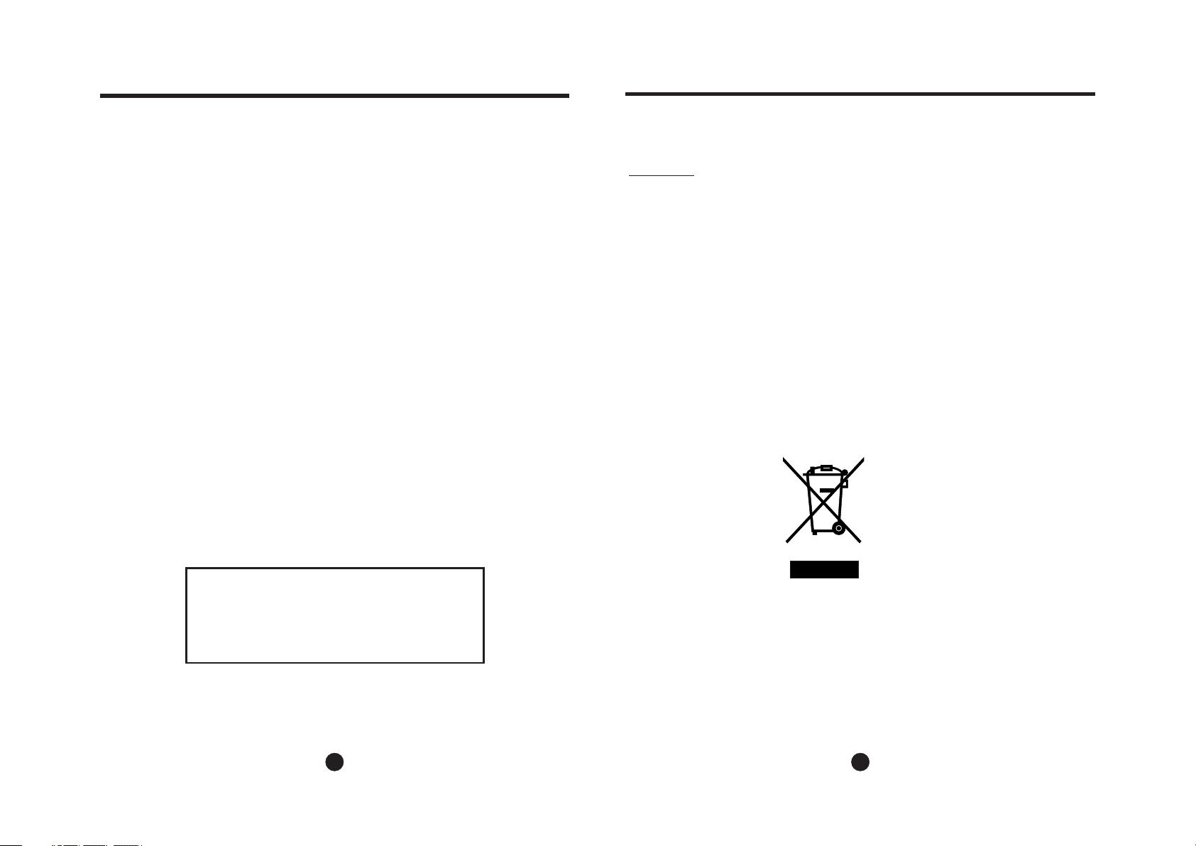
When using this air conditioner in the European countries, the following information must be followed:
DISPOSAL: Do not dispose this product as unsorted municipal waste. Collection of
such waste separately for special treatment is necessary.
It is prohibited to dispose of this appliance in domestic household waste.
For disposal, there are several possibilities:
A) The municipality has established collection systems, where electronic waste can be
disposed of at least free of charge to the user.
B) When buying a new product, the retailer will take back the old product at least free
of charge.
C) The manufacture will take back the old appliance for disposal at least free of charge
to the user.
D) As old products contain valuable resources, they can be sold to scrap metal dealers.
Wild disposal of waste in forests and landscapes endangers your health when
hazardous substances leak into the ground-water and find their way into the food chain.
NOTE
The rating data indicated on the energy label is based
on the testing condition of installing the un-extended
air exhaust duct without adaptor A & B (The duct and
the adaptor A & B are listed in the accessories chart
of the Instruction Manual).
1 2
Page 4
SAFETY PRECAUTIONS
Sa fety rul es
To prevent injury to the user or other people and property damage, the following instructions must be
followed. Incorrect operation due to ignoring of instructions may cause harm or damage.
Always do this
!
Your air conditioner should be used in such a way
that it is protected from moisture. e.g. condensation,
splashed water, etc. Do not place or store your air
conditioner where it can fall or be pulled into water
or any other liquid. Unplug immediately.
Always transport your air conditioner in a vertical
position and stand on a stable, level surface during
use.
Turn off the product when not in use.
Always contact a qualified person to carry out
repairs. If the supply cord is damaged it must be
repaired by a qualified repairer.
Keep an air path of at least 30cm all around the
unit from walls, furniture and curtains.
If the air conditioner is knocked over during use,
turn off the unit and unplug from the mains supply
immediately.
Energy Save
Do not operate your air conditioner in a wet room
such as a bathroom or laundry room.
Do not touch the unit with wet or damp hands or
when barefoot.
Do not press the buttons on the control panel with
anything other than your fingers.
Do not remove any fixed covers. Never use this
appliance if it is not working properly, or if it has
been dropped or damaged.
Never use the plug to start and stop the unit.
Always use the switch on the control panel.
Do not cover or obsturct the inlet or outlet grilles.
Do not use hazardous chemicals to clean or come
into contact with the unit. Do not use the unit in the
presence of inflammable substances or vapour such
as alcohol, insecticides, petrol,etc.
Do not allow children to operate the unit
unsupervised.
Do not use this product for functions other than
those described in this instruction manual.
Never do this
Use the unit in the recommended room size.
Locate the unit where furniture cannot obstruct the air flow.
Keep blinds/curtains closed during the sunniest part of the day.
Keep the filters clean.
Keep doors and windows closed to keep cool air in and warm air out.
Op era tin g condi tio n
The air conditioner must be operated within the temperature range indicated below:
IDENTIFICATION OF PARTS
WARNING
Do not store or use gasoline or other flammable vapors and liquids in the vicinity of this or any other
appliance.
Avoid fire hazard or electric shock. Do not use an extension cord or an adaptor plug. Do not remove
any prong from the power cord.
WARNING
Be sure the electrical service is adequate for the model you have chosen. This information can be found
on the serial plate, which is located on the side of the cabinet and behind the grille.
Be sure the air conditioner is properly grounded. To minimize shock and fire hazards, proper grounding is
important. The power cord is equipped with a three-prong grounding plug for protection against shock
hazards.
Your air conditioner must be used in a properly grounded wall receptacle. If the wall receptacle you intend
to use is not adequately grounded or protected by a time delay fuse or circuit breaker, have a qualified
electrician install the proper receptacle.
Ensure the receptacle is accessible after the unit installation.
For your s afety
El ect ric al In for m ati on
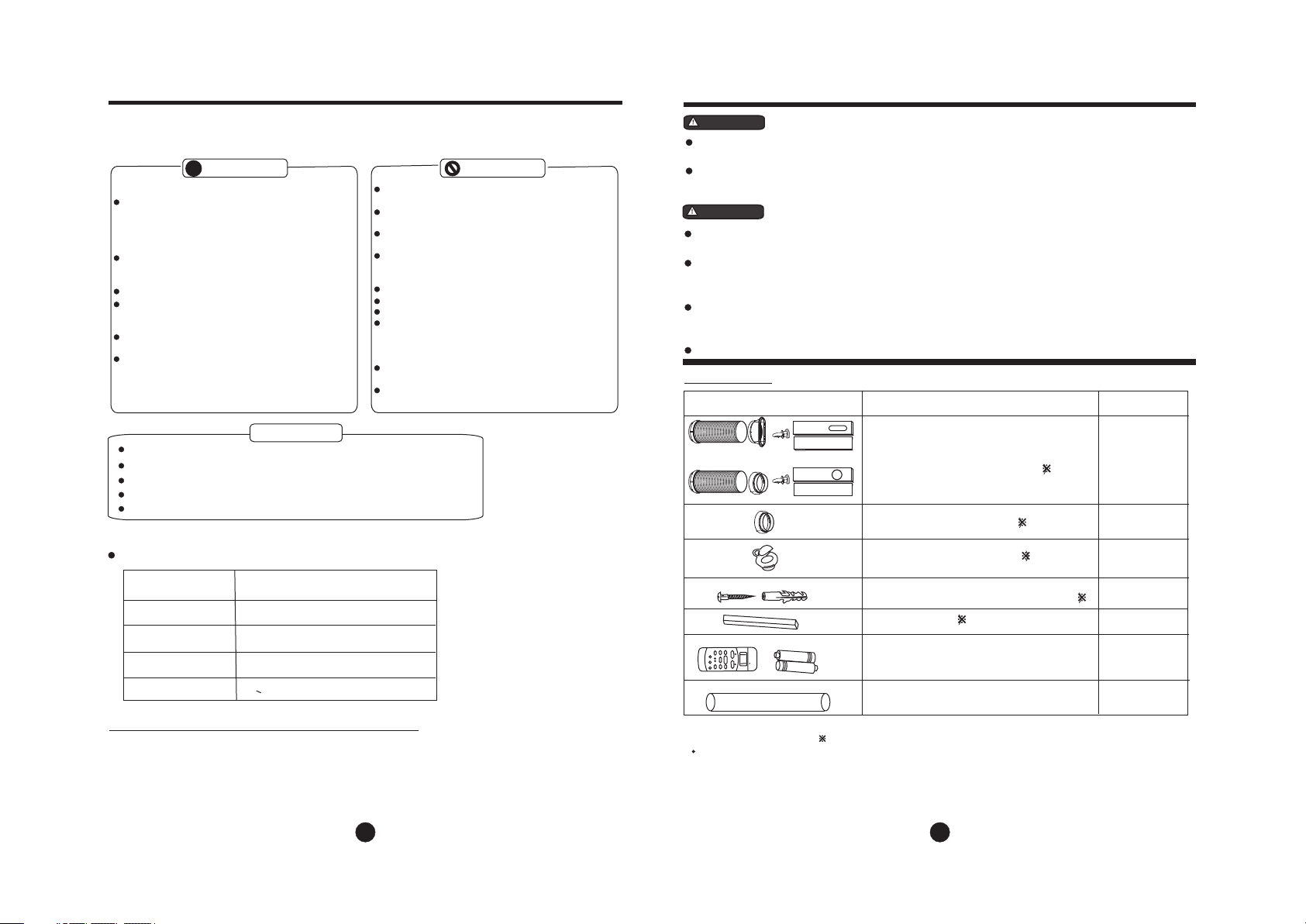
Accessories
PARTS :
or
PARTS NAME :
Exhaust hose(supplied),adapter B(round
mouth or flat month:depending on models)
and
Window Slider Kit and bolt
Adaptor B(round mouth)
()
()
Wall Exhaust Adaptor A( )
QUANTITY :
1 set
1 set
1 pc
MODE ROOM TEMPERATURE
COOL
DRY
HEAT(heat pump type)
HEAT(electrical heat type)
O O
17 C(62 F)~35
O O
13 C(55 F)~35
O O
5 C(41 F)~
O O
<30 C/88 F
O O
C(95 F)
O O
C(95 F)
O O
30 C(88 F)
Note: Perfo rm an ce m ay be reduced out si de o f th ese operating t em pe ratures.
Suggested tools for window kit installation
1. Screwd ri ver(med iu m si ze Philli ps )
2. Tape mea su re or ruler
3. Knife or s ci ssors
4. Saw(In t he e vent that t he w in dow kit nee ds t o be cut down i n si ze b ecause
the windo w is t oo narrow f or d ir ect insta ll ation)
3
Expansion Plug and wooden screw()
Foam seal
AUTO
COOL
DRY
HEAT
SET TEMPERA
MODE
SWING
ION
FOLLOW
ME
RESET LOCK
TEMP
ECONOMY
ON/OFF
TURE( C)
LED
DISPLAY
F
AN SPEED
TIMER OFF
TIMER ON
TURBO
F
HIGH
MED
LOW
AN
Remote Controller and Battery
(For remote control models only)
()
Drain hose
4/ pc
3/pc
1set
1pc
NOTE: Opt io nal parts ( ), s ome model s wi thout.
Check all the accessories are included in the package and please refer to the installation instructions for
their usage.
NOTE:
All the ill us tration s in t his manua l ar e for expla na tion purp os e only. You r air con di ti oner
may be slig ht ly differ en t. The actu al s hape shal l pr evail.
4
Page 5
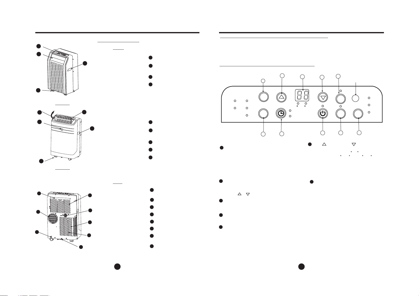
IDENTIFICATION OF PARTS
NAMES OF PARTS
1
2
4
3
Model A
2
3
4
Model B
6
7
8
Fig.1
1
5
Fig.2
9
10
11
12
13
Fig.3
Front
Rear
Operation Panel
1
Horizontal Louver Blade
2
(swing automatically)
3
Caster
4
Carrying Handle
(both sides)
Operation Panel
1
Horizontal Louver Blade
2
(manually)
Remote signal receptor
3
4
Caster
5
Carrying Handle
(both sides)
Upper Air Filter
6
(Behind the grille)
Air Outlet
7
Power cord outlet
8
Air intake
9
Drain Outlet
10
Air intake
11
Lower Air Filter
12
(Behind the grille)
13
Bottom tray drain outlet
AIR CONDITIONER FEATURES
EL EC TR ON IC C ON TR OL O PE RAT IN G INSTRU CTIONS
Befor e yo u be gin, th or oughly fa mi liari ze y ourself w it h the con tr ol panel an d re mote co nt roller
and all its f un ction s, t hen fol lo w th e symbo l fo r the fun ct io ns you de si re.
The uni t ca n be c ontro ll ed by the u ni t control p an el alon e or w ith the rem ot e contr ol ler .
NOTE: T hi s ma nual do es n ot incl ud e Remote Co nt rolle r Op eration s, s ee the << Re mote
Contr ol le r Instr uc tion> > pa cked with t he u nit for d et ails.
OPERATION PANEL OF THE AIR CONDITIONER
(Th e model h as no
aut o swing f eatur e
wit hou t thi s butto n)
9
SWI NG
AUT O
COO L
HEAT
DRY
FAN
MOD E
1
Fig.4
MODE select button
1
Selects the appropriate operating mode.
Each time you press the button, a mode
is selected in a sequence that goes from
AUTO, COOL, DRY, FAN and HEAT(cooling
only models without). The mode indicator light
illuminates under the different mode settings
Fig.4.
2
TIMER button
Used to initiate the AUTO ON start time and
AUTO OFF stop time program, in conjuction
with the & buttons.
3
POWER button
Power switch on/off.
SLEEP button
4
Used to initiate the SLEEP operation.
5
FAN button
Control the fan speed. Press to select the fan
speed in four steps-LOW, MED, HI and AUTO.
The fan speed indicator light illuminates under
different fan settings except AUTO speed. When
select AUTO fan speed, all the fan indicator lights
turn dark.
6
7
F
TIM ER ON
TIM ER OFF
2
6
C
3
UP( ) and DOWN( ) button
6
Used to adjust (increasing/decreasing)
temperature settings(1 C/2 F increments)
in a range of 17 C(62 F) to 30 C(88 F) or
the TIMER setting in a range of 0~24hrs..
NOTE: The control is capable of displaying
temperature in degrees Fahrenheit or degrees
Celsius. To convert from one to the other, press
and hold the Up and Down buttons at the same
time, for 3 seconds.
7
LED Display
Shows the s et t emper at ure in C
O
" F" an d th e Auto-tim er s ettin gs .
While on DR Y and FA N mo des, it s ho ws
the roo m te mp eratu re .
Error c od es a nd prot ec tion co de :
E1- Roo m te mp eratu re s ensor err or -
Unplu g th e un it and pl ug i t back in .
If erro r re pe ats, ca ll f or serv ic e.
E2- Eva po ra tor tem pe ratur e se ns or erro r Unplu g th e un it and pl ug i t back in .
If erro r re pe ats, ca ll f or serv ic e.
E4- Dis pl ay p anel co mm unicati on e rror-
Unplu g th e un it and pl ug i t back in .
If erro r re pe ats, ca ll f or serv ic e.
P1- Bot to m tr ay is ful l - Co nnect t he
drain h os e an d drain t he c ollec te d
water a wa y. If erro r re peats , ca ll
for ser vi ce .
Remote si gn al rece pt or
(Some mod el s have th e
signal re ce ptor on t he
8
front p an el , F ig.2)
ION
SLE EP
4
FAN
5
" " or
HI
MED
LOW
O
5
6
Page 6
OPERATING INSTRUCTIONS
ION button(optional)
8
Press t he I ON b utton , th e ion gen er ator
is ener g iz ed a nd will h el p to remo ve
polle n an d im pur iti es f rom the a ir, a nd
trap th em i n th e filte r. Pr ess it ag ai n to
stop th e fu nc tion.
SWING button
9
(Applicable to the models with auto swing feature only)
When th e op er ation i s ON , press t he
SWING b ut to n can sto p th e louve r at
the des ir ed a ngle. T he louv er s wing up
to an ang le o f 6 fo r each pr es s. Keep
press in g th e butto n mo re than 2 s ec onds
can ini ti at e the aut o sw ing fea tu re.
O
Operating Instructions
COOL operation
- Press the "MODE" button until the "COOL"
indicator light comes on.
- Press the ADJUST buttons "▲" or " " to
select your desired room temperature. The
temperature can be set within a range of
O O O O
17 C-30 C/62 F-88 F.
- Press the "FAN SPEED" button to choose the
fan speed.
HEAT operation(cooling only models without)
- Press the "MODE" button until the "HEAT"
indicator light comes on.
- Press the ADJUST buttons "▲" or " " to
select your desired room temperature. The
temperature can be set within a range of
O O O O
17 C-30 C/62 F-88 F.
- Press the "FAN SPEED" button to choose the
fan speed. For some models, the fan speed
can not be adjusted under HEAT mode.
DRY operation
- Press the "MODE" button until the "DRY" indicator
light comes on.
- Under this mode, you cannot select a fan speed or
adjust the temperature. The fan motor operates at
LOW speed.
- Keep windows and doors closed for the best
dehumidifying effect.
- Do not put the duct to window.
AUTO operation
- When you set the air conditioner in AUTO
mode, it will automatically select cooling,
heating(cooling only models without), or fan
only operation depending on what temperature
you have selected and the room temperature.
▲
▲
- The air conditioner will control room
temperature automatically round the
temperature point set by you.
- Under AUTO mode, you can not
select the fan speed.
FAN operation
- Press the "MODE" button until the
"FAN " indicator light comes on.
- Press the "FAN SPEED" button to
choose the fan speed. The temperature
cannot be adjusted.
- Do not put the duct to window.
TIMER operation
- When th e un it i s on, fir st p ress th e
Timer bu tt on, the TIM ER OFF
indic at or l ight il lu minat es . It indi cates t he Au to Stop pro gr am is
initi at ed .
- When th e un it is off , fi rst pre ss t he
Timer bu tt on, the TIM ER ON ind ic ator li gh t il lumin at es. It in di cates
the Auto S ta rt progra m is i nitia te d.
- Press o r ho ld the UP or DO WN
butto n to c hange the Au to t ime by
0.5 hou r in crement s, u p to 10 hou rs ,
then at 1 h ou r increme nt s up to 24
hours . The contr ol w ill cou nt d own
the tim e re maining u nt il star t.
- The s el ected tim e wi ll regi st er in 5
secon d an d th e syste m wi ll auto m atica ll y re vert ba ck t o displ ay t he
previ ou s te mpera tu re sett in g.
- Turnin g th e un it ON or OF F at a ny
time or a dj us ting th e ti mer set ti ng
to 0.0 wi ll c an cel the Au to S tart/
Stop ti me d program .
- When th e ma lfuncti on ( E1 or E2)
occur s, t he Auto Star t/ Stop ti me d
progr am w il l also be c an celle d.
SLEEP operation
Press this button, the selected temperature
will increase(cooling) or decrease(heating)
O O
by 1 C/2 F 30 minutes.The temperature
will then increase(cooling) or decrease
(heating) by another 1 C/2 F after an
additional 30 minutes. This new temperature will be maintained for 7 hours
before it returns to the originally selected
temperature. This ends the Sleep mode
and the unit will continue to operate as
originally programmed.
NOTE: This feature is unavailabe under
FAN or DRY mode.
O O
Adjust ma nu ally
Swing aut om atica ll y
Fig.5
Fig.6
OPERATING INSTRUCTIONS
Other features
Auto-Restart(on some models)
If the unit b re aks off u nexpect ed ly due to t he
power cut ,i t will re st art with th e pr evious
functio n se tting a ut omatica ll y when the po we r
resumes .
Wait 3 minutes before resuming operation
After the u ni t has sto pp ed, it can no t be r estar te d
operati on i n the fir st 3 m inutes. T his is to p ro tect
the unit. O pe ratio n wi ll automa ti cally sta rt a fter
3 minutes .
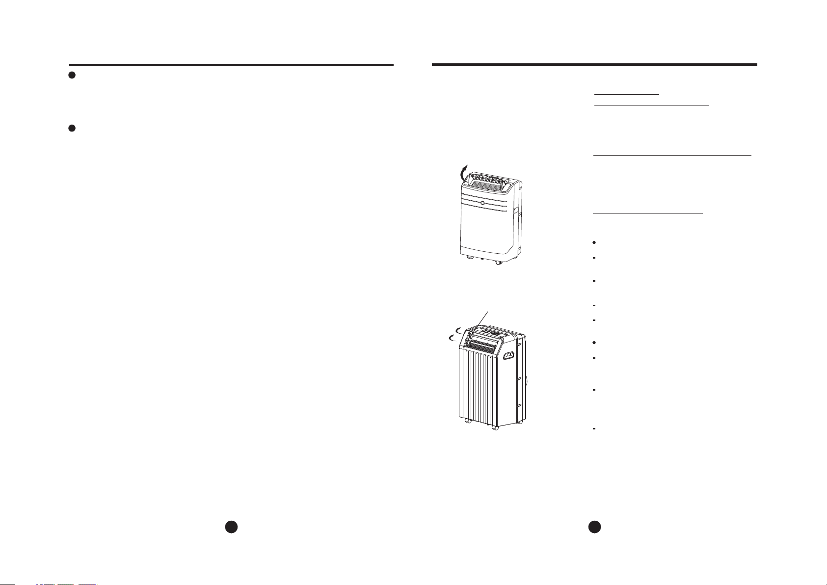
Air flow direction adjustment
The louve r ca n be adju st ed manual ly o r
automat ic ally ac co rding to th e di ffe re nt models .
Adjus t th e ai r flow di re ction man ua lly
(Fig. 5) :
The l ou ve r can be se t to t he desire d po sitio n
manuall y. The m ax s ettin g an gl e is abou t
O
60 , p le ase do not fo rc e to set an y la rg er.
Do not plac e an y heavy o bj ects or oth er l oads
on the louv er, d oing so w il l cause dam ag e to
the unit.
Ensur e th e lo uver is f ul ly opened u nd er
heating o pe ratio n.
Keep the lo uv er full y op ened duri ng
operati on .
Adjus t th e ai r flow di re ction aut om atica ll y
(Fig. 6) :
When oper at ion is ON , th e louver op en s fully.
Use the SWI NG b utton o n th e remote
control le r can sto p th e louver at t he d esire d
angle.
The l ou ve r move up t o an a ngle of 6 for
each pres s un til it mo ve t o a positio n wh ich
would aff ect the c oo ling or hea ti ng effe ct
of the ai r co nd ition er, i t would aut om atica ll y
change th e sw ing dir ec tion.
If keep p re ss ing the S WI NG button m or e
than 2 seco nd s, the au to s wing feat ur e is
activat ed . The l ou ver swing s as s hown in
Fig.6
O
7
8
Page 7

INSTALLATION INSTRUCTIONS (optional)
INSTALLATION INSTRUCTIONS (optional)
or
B
A:3 0c m-1 00cmAB:≥30 cm
Horiz ont al
windo w
Win do w Sli der Kit
Minim um: 67.5c m(2 .22ft ).
Maxmu m:1 23cm( 4.0 4ft).
or
Horiz ont al
windo w
Win do w Sli der Kit
Minim um: 67.5c m(2 .22ft ).
Maxmu m:1 23cm( 4.0 4ft).
Horiz ont al
windo w
Win do w Sli der Kit
Minim um: 67.5c m(2 .22ft ).
Maxmu m:1 23cm( 4.0 4ft).
or
Horiz ont al
windo w
INSTALLATION INSTRUCTIONS
Lo catio n
Foam seal A
(adhesive type)
The air conditioner should be placed on a firm
foundation to minimize noise and virbration. For
safe and secure positioning, place the unit on a
B
Fig.7
smooth, level floor strong enough to support the unit.
A
The unit has casters to aid placement, but it should
only be rolled on smooth, flat surfaces. Use caution
when rolling on carpet surfaces. Do not attempt to
roll the unit over objects.
The unit must be placed within reach of a properly
Fig.1 0
Window kit
rated grounded socket.
Never place any obstacles around the air inlet or
outlet of the unit.
Allow 30cm to 100cm of space from the wall with
26.5 ~ 48.0
or
Window stool
window for efficient air-conditioning.
Installation in a double-hung sash
window
1. Cut the foam seal(adhesive type) to the proper
length and attach it to the window stool. Fig.10
2. Attach the window slider kit to the window stool.
Adjust the length of the window slider kit according
to the width of window, shorten the adjustable window
kit if the width of window is less than 26.5 inches.Open
the window sash and place the window slider kit on the
window stool. See Fig.11.
3. Cut the foam seal(adhesive type) to the proper
length and attach it on the top of the window. Shown
as in Fig.12.
Window Slider kit Installation
Your window slider kit has been designed to fit most
standard "Vertical" and "horizontal"window
applications, However, it may be necessary for you to
improvise/modify some aspects of the installation
procedures for certain types of window. Please refer
to Fig. 8& Fig.9 for minimum and maximum window
openings.Window slider kit can be fixed with a bolt
26.5 ~ 48.0
Window kit
Window stool
Fig.11
4. Close the window sash securely against the
window.
5. Cut the foam seal to an appropriate length and
seal the open gap between the top window sash
and outer window sash. Shown as in Fig.13.
(see Fig.9a).
Note: If the window opening is less than the mentioned
minimum length of the window slider kit, cut that one
Fig.8
with a hole in it short to fit for the window opening. Do
Window kit
never cut out the hole in window slider kit.
or
Window stool
bolt
Win do w sli der kit
or
Fig.9a
bolt
Win do w
slide r kit
Foam seal
Window kit
Window stool
Fig.1 2
Win do w Sli der Kit
Minim um: 67.5c m(2 .22ft ).
Maxmu m:1 23cm( 4.0 4ft).
Fig.1 3
Fig.9
9 10
Page 8

INSTALLATION INSTRUCTIONS (optional)
INSTALLATION INSTRUCTIONS (optional)
Window
panel
Window
panel
Exhaust hose installation:
The exhaust hose and adaptor must be installed or removed
in accordance with the usage mode.
COOL,HEAT(heat pump type) or AUTO
mode
FAN,DEHUMIDIIFY or HEAT(electrical heat type)
mode
1. Install the window Exhaust adaptor B onto the exhaust
hose as shown in Fig.18a. or Fig.18b. Refer to the previous
pages for window kit installation.
2. Place the Exhaust hose over against the air outlet opening
Install
Remove
Foam seal A
(adhesive type)
Fig.1 4
26.5 ~ 48.0
Installation in a sliding sash
window
1. Cut the foam seal(adhesive type) to the proper
length and attach it to the window frame,Fig.14.
2. Attach the window slider kit to the window stool.
Adjust the length of the window slider kit according
to the width of window, shorten the adjustable window
kit if the width of window is less than 26.5 inches. Open
the window sash and place the window slider kit on the
window stool. See Fig.15.
Fig.1 8a
h i
us
P
n
Hook
Fig.1 8b
Fig.1 9
hook(See Fig.19) and flat the other end(See Fig.20) for
or
3. Cut the foam seal(adhesive type) to the proper
length and attach it on the top of the window.
Shown as in Fig.16.
quick installation.
The exhaust hose can be installed into the wall
(Not applicable to the units without adaptor A, expansion
plugs and wooden screws of Accessories ).
1. Prepare a hole in the wall. Install the wall Exhaust adaptor A
onto the wall(outside) by using 4 expansion plugs and
wooden screws, be sure to fix thoroughly. (See Fig.21)
2. Attach the Exhaust hose to wall Exhaust adaptor A.
Note:
Cover the hole using the adaptor cap when not in use.
The duc t can be co mpresse d or exte nd ed mode ra tely
accordi ng to the i nstalla ti on requ ir ement, bu t it is
desirab le to kee p the duc t length to a mini mu m.
IMPORTANT:
DO NOT OVER BEND THE DUCT (SEE Fig.22)
or
26.5 ~ 48.0
Fig.1 5
4. Close the sliding sash securely against the window.
5. Cut the foam seal to an appropriate length and
seal the open gap between the top window sash
and outer window sash. Shown as in Fig.17.
Expansion plug
position
Adaptor A
Adaptor
cap
Fig.2 0
Foam seal
Fig.1 6
Fig.1 5
11
max 120CM
min 30CM
Fig.2 1
Fig.2 2
CAUTION:
Make sure that there is no obstacle around the air outlet of
the exhaust hose (in the range of 500mm) in order to the
exhaust system works properly.
12
Page 9

INSTALLATION INSTRUCTIONS
CARE AND MAINTENANCE
Remov e th e
drain p lu g
Fig.2 3
Conti nuous
drain h ose
Fig.2 4
Fig.2 5
Water drainage:
- During dehumidifying modes, remove the drain
plug from the back of the unit, install the drain
connector(5/8 universal female mender) with
3 4 hose(locally purchased). For the models
without drain connector, just attach the drain
hose to the hole. Place the open end of the
hose directly over the drain area in your
basement floor. Please refer to Fig.23 & 24.
- When the water level of the bottom tray reaches
a predetermined level,
the digital display area shows "P1". At this time
the air conditioning/dehumidification process will
immediately stop. However, the fan motor will
continue to operate(this is normal).
Carefully move the unit to a drain location,
remove the bottom drain plug and let the
water drain away(Fig.25). Restart the machine
until the "P1" symbol disappears. If the error
repeats, call for service.
NOTE: Be sure to reinstall the bottom drain plug
before using the unit.
the unit beeps 8 times,
Remov e the
scr ew a nd
tak e th e air
inlet g ril le
down
Band
Fig.2 7
Remov e the a ir filt er
out fro m the g rille
Air fil ter
(slid e out)
Fig.26
Fig.2 8
Power cord
Fig.29
CARE AND MAINTENANCE
IMPORTANT:
1) Be sure to unplug the unit before cleaning or servicing.
2) Do not use gasoline, thinner or other chemicals to clean
the unit.
3) Do not wash the unit directly under a tap or using a hose.
It may cause electrical danger.
4) If the power cord is damaged, it should be repaired by
manufacture or its agency.
1. Air filter
- Clean the air filter at least once every two weeks to prevent
inferior fan operation because of dust.
- Removal
This unit has two filter. Grasp the upper filter tab(Fig.26),
pull the filter out then up . Remove the lower filter by
loosening the screw, taking down the air inlet grille, then
removing the air filter as shown in Fig.27 & 28.
- Cleaning
Wash the air filter by immersing it gently in warm water
(about 40 C/104 F) with a neutral detergent. Rinse the filter
and dry it in a shady place.
- Mounting
Insert the upper air filter from upward after cleaning, attach
the lower air filter on the air inlet grille, then install the grille
by using the screw.
2. Unit enclosure
- Use a lint-free cloth soaked with neutral detergent to clean
the unit enclosure. Finished by a dry clean cloth.
3. Unit idle for a long time
- Remove the rubber plug at the back of the unit and attach
a hose to drain outlet. Place the open end of the hose
directly over the drain area in your basement floor
(See Fig.23 & 24).
- Remove the plug from the bottom drain outlet, all the water
in the bottom tray would drain out (See Fig.25).
- Keep the appliance running on FAN mode for half a day in
a warm room to dry the appliance inside and prevent mold
forming.
- Stop the appliance and unplug it, wrapped the cord and
bundle it with the tape(Fig.29). Remove the batteries from
the remote controller.
- Clean the air filter and reinstall it.
- Unscrew the exhaust hose to the right or left and pull out
for uninstallation(Fig.30), keep it safety, and cover the
window(wall) hole with the adaptor cap.
,,
O O
,,
,, ,,
13
Fig.30
14
Page 10

TROUBLESHOOTING TIPS
TROUBLE SHOOTING
TROUBLES
1. Unit does not
Start when
Pressing on/off
Button
2. Not cool enough
4. Noisy or vibration
5. Gurgling sound
6. Power shut off at
Heating mode
POSSIBLE CAUSES
- P1 appears in the display window
- Room temperature is lower than
the set temperature.(Cooling mode)
- The windows or doors in the room
are not closed.
- There are heat sources inside the
room.
- Exhaust air duct is not connected or
blocked.
- Temperature setting is too high.
- Air filter is blocked by dust.
- The ground is not level or not flat
enough.
- The sound comes from the flowing
of the refrigerant inside the
air-conditioner.
- The a ut oma ti c ove r he at
prote ction f un cti on . Whe n th e
tempe ratur e at t he ai r ou tle t
excee d 70 C/15 8 F,th e de vice
wi
ll st
O O
op.
SUGGEST REMEDIES
Drain the water in the bottom tray.
Reset the temperature.
Make sure all the windows and
doors are closed.
Remove the heat sources if possible.
Connect the duct and make
sure it can function properly.
Decrease the set temperature.
Clean the air filter.
Place the unit on a flat, level
ground if possible.
It is normal.
Switch on again after the unit
has cool down.
NOTE
The rating data indicated on the energy label is based
on the testing condition of installing the un-extended
air exhaust duct without adaptor A & B (The duct and
the adaptor A & B are listed in the accessories chart
of the Instruction Manual).
15
Page 11

The design and specifications are subject to change without
prior notice for product improvement. Consult with the sales
agency or manufacturer for details.
AIR CONDITIONER
REMOTE CONTROLLER ILLUSTRATION
Than k you very mu ch for purcha sing our ai r condition er.
Plea se read thi s owner's man ual caref ully before u sing
your a ir condit ioner.
Page 12

CONTENTS
Handling the remote controller ......................................................
Remote controller Specifications...................................................
Function buttons .................. .........................................................
Indicators on LCD ..........................................................................
How to use the buttons .................................................................
Handling the remote controller
Location of the remote controller.
2
3
4
6
8m
SET TEMPERA
AUTO
TURE( C)
COOL
DRY
HEAT
FAN
HIGH
MED
LOW
TEMP
MODE
ON/OFF
SWING
F
AN SPEED
ECONOMY
ION
TIMER ON
RESET LOCK
FOLLOW
TIMER OFF
ME
LED
DISPLAY
TURBO
Use the remote controller within a distance of 8
meters from the appliance, pointing it towards the
receiver. Reception is confirmed by a beep.
7
Auto operation.................................................................................
Cooling/Heating/Fan operation......................................................
Dehumidifying operation ...............................................................
Swing operation..............................................................................
Timer operation...............................................................................
ECONOMY operation ....................................................................
12
7
7
CAUTIONS
The air conditioner will not operate if curtains, doors or other materials
8
8
9
block the signals from the remote controller to the indoor unit.
Prevent any liquid from falling into the remote controller. Do not expose
the remote controller to direct sunlight or heat.
If the infrared signal receiver on the indoor unit is exposed to direct
sunlight, the air conditioner may not function properly. Use curtains to
prevent the sunlight from falling on the receiver.
If other electrical appliances react to the remote controller. either move
these appliances or consult your local dealer.
Replacing batteries
The remote controller is powed by two dry
batteries(R03/LR03X2) housed in the rear
part and protected by a cover.
(1) Remove the cover by pressing and sliding off.
(2) Remove the old batteries and insert the new
batteries,placing the(+) and (-) ends correctly.
(3) Reattach the cover by sliding it back into
position.
.
NOTE: When the batteries are removed, the
remote controller erases all programming.
After inserting new batteries, the remote
controller must be reprogrammed.
1
2
Page 13

CAUTIONS
Do not mix old and new batteries or batteries of a different type.
Do not leave the batteries in the remote controller if it is not going
to be used for 2 or 3 months.
Dispose of the old batteries in the special containers to be found
in the sales outlets.
Remote Controller Specifications
RG51B1/(C)EU, RG51B14/(C)E,RG51B31/(C)E
Model
RG51B/(C)EU, RG51B16/(C)E,RG51B31/(C)EU
RG51B17/(C)EU, RG51B18/(C)E,RG51B32/(C)EU
RG51B19/(C)E-M, RG51B20/(C)E,RG51B30/(C)EU
RG51B25/(C)E, RG51B26/(C)EU;RG51B27/(C)E,
RG51B30/(C)E.
Rated Voltage
Lowest Voltage of
CPU Emitting Signal
Signal Receiving
Range
Environment
3.0V(Dry batteries R03/LR03×2)
2.0V
8m
。 。
-5 C 60 C( )
~
O O
-41 F~140 F
NOTE:
Temperature setting display:
Celsius scale( C):
Fahrenheit scale( F):
RG51B14/(C)E, RG51B16/(C)E,RG51B18/(C)E,RG51B31/(C)E,RG51B19/(C)E-M,
RG51B20/(C)E,RG51B25/(C)E,RG51B27/(C)E,RG51B30/(C)E.
RG51B/(C)EU, RG51B1/(C)EU,
RG51B17/(C)EU,RG51B26/(C)EU,
RG51B30/(C)EU,RG51B32/(C)EU,RG51B31/(C)EU.
Performance Feature
1. Operating Mode: AUTO, COOL, DRY, HEAT(Cooling only
model without), and FAN.
2. Timer Setting Function in 24 hours.
3. Indoor Setting Temperature Range : 17 C~30 C(62 F~88 F).
。 。
O O
4. Full function of LCD (Liquid Crystal Display)
NOTE:
All th e illustr ations in thi s manual ar e for explana tion purp ose only.
Your ai r conditi oner may be sli ghtly dif ferent.Th e actual sh ape shall
prev ail.
Function buttons
SET TEMPERATURE( C)
AUTO
COOL
DRY
HEAT
1
MODE
3
SWING
4
5
Model: RG51B14/(C)E,
RG51B16/(C)E,
RG51B18/(C)E,
RG51B19/(C)E-M,
RG51B20/(C)E
RG51B31/(C)E
RG51B30/(C)E.
NOTE:
RG51B16/(C)E ,RG51B18/(C)E
models have no SWING feature;
RG51B18/(C)E ,RG51B19/(C)E-M,
RG51B20/(C)E models have no
LED DISPLAY feature.
RG51B19/(C)E-M model has no
MED FAN feature.
RG51B31/(C)E model ECONOMY button is instead of SLEEP
button.
RG51B30/(C)E model has no
MED FAN and SWING features.
SET TEMPERATURE( C)
AUTO
COOL
DRY
HEAT
1
MODE
3
SWING
4
ION
14
5
Model: RG51 B2 5/(C)E;
RG51B27 /( C) E.
NOTE:
TEMP
ON/OFF
ECONOMY
RESET LOCK
TEMP
ON/OFF
ECONOMY
RESET LOCK
LED
DISPLAY
LED
DISPLAY
FAN SPEED
TIMER ON
TIMER OFF
FAN
HIGH
MED
LOW
FAN SPEED
TIMER ON
TIMER OFF
FAN
HIGH
MED
LOW
2
6
7
8
9
10
11
12
2
6
7
8
9
10
11
12
RG51B25/(C)E model has no
SWING feature.
1
TEMP DOWN Button
Push this button to decrease the indoor temperature setting in 1 C(2 F) increments to 30 C(88 F).
TEMP UP Button
2
Push this button to increase the indoor temperature setting in 1 C(2 F) increments to 17 C(62 F).
3
MODE Button
o o
o o
Each time the button is pressed, the operation
mode is selected in the sequence of the following:
AUTO
NOTE: Heat mode is for Cooling & Heating models only.
SWING Button(on some models)
4
COOL
DRY
HEAT FAN
Used to stop or start louver movement and
set the desired up/down airflow direction.
5
RESET Button
Once the recessed RESET button is pressed,
all of the current settings will be cancelled
and the controller will return to the initial settings.
6
ON/OFF Button
Operation starts when this button is pressed
and stops when the button is pressed again.
7
FAN SPEED Button
Used to select the fan speed in four steps:
Auto Low Med High
Some models have no MED FAN feature.
8
TIMER ON Button
Press this button to activate the Auto-on time
setting. Each press will increase the time setting
in 30 minutes increments, up to 10 hours, then at
1 hour increments up to 24 hours. To cancel the
Auto-on time setting, just press the button until
the time setting is 0.0.
9
ECONOMY(SLEEP) Button
Select this function during the sleeping time. It
can maintain the most comfortable temperature
and save energy. This function is available on
COOL, HEAT or AUTO mode only .
3 4
Page 14

Function buttons(continued)
SET TEMPERATURE( F)
AUTO
COOL
DRY
HEAT
MODE
SWING
FOLLOW
ME
Model: RG51B1/(C)EU,
RG51B/(C)EU,
RG51B26/(C)EU,
RG51B30/(C)EU,
RG51B32/(C)EU,
RG51B31/(C)EU.
NOTE: RG51B/(C)EU models
have no SWING and FOLLOW ME
buttons ;RG51B1/(C)EU models
have no FOLLOW ME button;
RG51B30/(C)EU models have no
SWING ,FOLLOW ME buttons and
MED FAN feature,and SLEEP button
instead of ECONOMY button;
RG51B32/(C)EU models have no
FOLLOW ME button and MED FAN
feature,and SLEEP button instead of
ECONOMY button;RG51B31/(C)EU
models have on FOLLOW ME button.
SET TEMPERATURE( F)
AUTO
COOL
DRY
HEAT
MODE
SWING
ION
TEMP
SENSING
TEMP
ON/OFF
ECONOMY
RESET LOCK
LED
DISPLAY
TEMP
ON/OFF
SLEEP
RESET LOCK
LED
DISPLAY
FAN
HIGH
MED
LOW
FAN SPEED
TIMER ON
TIMER OFF
FAN
HIGH
MED
LOW
FAN SPEED
TIMER ON
TIMER OFF
10
11
12
13
14
9
13
14
Model: RG 51B17/(C)EU
While the unit is running under SLEEP mode,
NOTE:
it would be cancelled if ON/OFF, FAN SPEED, SLEEP
or MODE button is pressed.
TIMRT OFF Button
Press this button to activate the Auto-off time
setting. Each press will increase the time setting
in 30 minutes increments, up to 10 hours, then at
1 hour increments up to 24 hours. To cancel the
Auto-off time setting, just press the button until
the time setting is 0.0.
LOCK Button
Press this recessed button to lock all current
settings, and the remote controller will not accept
any operation except that of the LOCK. Use the
LOCK mode when you want to prevent settings
from being changed accidentally. Press the LOCK
button again to cancel the LOCK function. A lock
symbol will appear on the remote controller display
when the lock function is activated.
LED Display Button
Press this button to clear the display on the
indoor unit, press it again to light the display .
NOTE:
RG51B18/(C)E ,RG51B19/(C)E-M,
RG51B20/(C)E models have no this feature.
FOLLOW ME/TEMP SENSING Button
Press this button to initiate FOLLOW ME function.
When the Follow Me function is activated, the
remote display is actual temperature at its location.
The remote control will send this signal to the air
conditioner every 3 minutes interval until press
the Follow Me button again.
The Follow Me function is not available under
DRY and FAN mode.
Switch the operation mode or turn off the unit will
cancel the follow me function automatically.
ION Button
When push this button, the ion generator is
energized and will help to remove pollen and
impurities from the air.
Indicators on LCD
SET TEMPERATURE
TIMER ON OFF
MODE display
Displays the current selected mode. Including AUTO,
COOL, DRY, HEAT (cooling & heating models only)
and FAN.
Transmission Indicator
This transmission indicator will light when remote
controller transmits signals to the indoor unit.
Temp./Timer display
The temperature setting (from 17 C(62 F) to
O O
30 C(88 F)) or timer setting (0~24h) will be displayed.
O O
If FAN mode is selected, there will be no display.
ON/OFF display
This indicator will be displayed when
the unit is operating.
MODE display(FAN mode)
FAN SPEED display
Displays the selected fan speed: AUTO, HIGH,
and LOW. Nothing displays when the fan speed is
selected in AUTO speed. When AUTO or DRY Mode
is selected, there will be no signals displayed.
NOTE:
RG51B19/(C)E-M model has no MED
MED
FAN speed feature.
FOLLOW ME display
When pressing FOLLOW ME/TEMP SENSING button
in COOL or HEAT mode, the remote sensing function
is activated and this indicator displays.
TIMER display
This display area shows the settings of the TIMER.
That is, if only the Auto-on time function is set, it will
display TIMER ON. If only the Auto-off time function
is set, it will display TIMER OFF. If both functions are
set, it will display TIMER ON OFF which indicates you
have chosen both the Auto-on time and Auto-off time.
LOCK Indicator
LOCK display is displayed when pushing the LOCK
button. Push the LOCK button to clear display.
5 6
Page 15

How to use the buttons
Dehumidifying operation
SET TEMPERATURE( C)
AUTO
COOL
DRY
HEAT
2
1
MODE
SWING
TEMP
ON/OFF
ECONOMY
RESET LOCK
LED
DISPLAY
FAN
HIGH
MED
LOW
FAN SPEED
TIMER ON
TIMER OFF
Ensu re the unit i s plugged in an d power is
avai lable. The OPER ATI ON indicato r on the
disp lay panel o f the indoor un it illumi nates.
1. Pre ss the MODE button to sele ct Auto.
3
2. Pre ss the TEMP but ton to set th e desired
temp erature . The te mperatu re can be set
with in a range of 1 7 C(62 F)~ 30 C in 1 C( 2 F)
incr ements.
3. Pre ss the ON/OFF button to s tart the air
cond itioner.
Auto operation
2
1
NOTE
1. In the Auto mode, the air conditioner can logically
choose the mode of Cooling, Fan, Heating and
Dehumidifying by sensing the difference between the
actual ambient room temperature and the set temper ature on the remote controller.
2. In the Auto mode, you can not switch the fan speed.
It has already been automatically controlled.
3. If the Auto mode is not comfortable for you , the
desired mode can be selected manually.
SET TEMPERATURE( C)
AUTO
COOL
DRY
HEAT
TEMP
FAN
HIGH
MED
LOW
Cooling /Heating/Fan operation
Ensu re the unit i s plugged in an d power is
avai lable.
1. Pre ss the MODE button to sele ct COOL, HE AT,
(coo ling & heat ing models on ly) or FAN mod e.
2
1
MODE
SWING
ON/OFF
ECONOMY
RESET LOCK
LED
DISPLAY
FAN SPEED
TIMER ON
TIMER OFF
2. Pre ss the TEMP but ton to set th e desired
4
temp erature . The te mperatu re can be set
3
with in a range of 1 7 C(62 F)~ 30 C in 1 C( 2 F)
incr ements.
3. Pre ss the FAN SPE ED button to se lect the
fan sp eed in four s te ps- Auto, Lo w, Med,or Hi gh.
4. Pre ss the ON/OFF b utton to st art the air
1
cond itioner.
NOTE
In the FAN mode, the setting temperature is not
displayed in the remote controller and you are not
able to control the room temperature either. In this
case, only step 1, 3 and 4 may be performed.
SET TEMPERATURE( C)
AUTO
COOL
DRY
HEAT
TEMP
ON/OFF
MODE
SWING
ECONOMY
RESET LOCK
SET TEMPERATURE( C)
AUTO
COOL
DRY
HEAT
MODE
SWING
LED
DISPLAY
TEMP
ON/OFF
ECONOMY
RESET LOCK
LED
DISPLAY
FAN
HIGH
MED
LOW
FAN SPEED
TIMER ON
TIMER OFF
FAN SPEED
TIMER ON
TIMER OFF
FAN
HIGH
MED
LOW
Ensu re the unit i s plugged in an d power is
avai lable. The OPER ATI ON indicato r on the
disp lay panel o f the indoor un it illumi nates.
1. Pre ss the MODE button to sele ct DRY mod e.
2. Pre ss the TEMP but ton to set th e desired
temp erature . The te mperatu re can be set
3
with in a range of 1 7 C(62 F)~ 30 C in 1 C( 2 F)
incr ements.
3. Pre ss the ON/OFF b utton to st art the air
cond itioner.
NOTE
In the Dehumidifying mode, you can not switch
the fan speed. It has already been automatically
controlled.
Swing operation(on some models)
Use the SWING button to adjust the Up/Down
airflow direction .
1. When press the button once and quickly, the
air flow direction setting feature of the louver is
activated. The moving angle of the louver is
o
6 for each press. Keep pressing the button to
move the louver to the desired position.
NOTE:On some models press it to initiate the Auto
swing feature only.
2. If keep pressing the SWING button without
releasing for 2 more seconds, the auto swing
feature of the louver is activated. The horizontal
louver would swing up/down automatically.
Press it again to stop.
NOTE: When the louver swing or move to a
position which would affect the cooling
and heating effect of the air conditioner,
it would automatically change the swing/
moving direction.
7 8
Page 16

SET TEMPERATURE( C)
AUTO
COOL
DRY
TIMER ON
HEAT
TEMP
ON/OFF
MODE
SWING
ECONOMY
RESET LOCK
LED
DISPLAY
FAN
HIGH
MED
LOW
FAN SPEED
TIMER ON
TIMER OFF
Timer operation
press the TIMER ON button can set the auto-on
time of the unit. And press the TIMER OFF button
can set the auto-off time of the unit.
To set the Auto-on time.
1. Press the TIMER ON button. The remote
controller shows TIMER ON, the last Auto-on
setting time and the signal "h" will be shown on
the LCD display area. Now it is ready to reset the
Auto-on time to START the operation.
2. Push the TIMER ON button again to set desired
Auto-on time. Each time you press the button,
the time increases in 30 minutes increments, up
to 10 hours, then at 1 hour increments up to 24
1
hours.
2
3. After setting the TIMER ON ,there will be a one half second delay before the remote controller
transmits the signal to the air conditioner. Then,
after approximately another 2 seconds, the
signal "h" will disappear and the set temperature
will re-appear on the LCD display window.
To set the Auto-off time.
1. Press the TIMER OFF button. The remote
controller shows TIMER OFF, the last Auto-off
setting time and the signal "h" will be shown on
the LCD display area. Now it is ready to
reset the Auto-off time to START the operation.
2. Push the TIMER OFF button again to set desired
Auto-off time. Each time you press the button,
the time increases in 30 minutes increments, up
to 10 hours, then at 1 hour increments up to 24
hours.
3. After setting the TIMER OFF ,there will be a one half second delay before the remote controller
transmits the signal to the air conditioner. Then,
after approximately another 2 seconds, the
signal "h" will disappear and the set temperature
will re-appear on the LCD display window.
IMPORTANT
The effective operation time set by the remote controller for the timer
function is limited to the following settings: 0.5, 1.0, 1.5, 2.0, 2.5, 3.0,
3.5, 4.0, 4.5, 5.0, 5.5, 6.0, 6.5, 7.0, 7.5, 8.0, 8.5, 9.0, 9.5, 10, 11, 12, 13,
14, 15,16,17, 18, 19, 20, 21, 22, 23 and 24.
Example of Timer setting
TIMER ON
(Auto-on Operation)
h
TIMER ON
The TIMER ON feature is useful when you want
the unit to turn on automatically before say when
you return home. The air conditioner will automatically start operating at the set time.
Example:
To start the air conditioner in 6 hours.
1. Press the TIMER ON button, the last setting of
starting operation time and the signal "h" will
Set
Start
Off
6 hours later
show on the display area.
2. Press the TIMER ON button to display "6:0h" on
the TIMER ON display of the remote controller.
3. Wait for about 3 seconds and the digital display
area will show the temperature again. Now this
function is activated.
9
10
Page 17

h
TIMER OFF
Stop
On
Set 10 hours later
h
TIMER ON OFF
2 hours later
after setting
Stop
10 hours later
after setting
On
Set
Start
TIMER OFF
(Auto-off Operation)
The TIMER OFF feature is useful when you want
the unit to turn off automatically after you go to bed.
The air conditioner will stop automatically at the set
time.
Example:
To stop the air conditioner in 10 hours.
1. Press the TIMER OFF button, the last setting of
stopping operation time and the signal "h" will
show on the display area.
2. Press the TIMER OFF button to display "10h" on
the TIMER OFF display of the remote controller.
3. Wait for about 3 seconds and the digital display
area will show the temperature again. Now this
function is activated.
COMBINED TIMER
(S both ON and OFF )etting timers simultaneously
TIMER OFF → TIMER ON
(On → Stop → Start operation)
This feature is useful when you want to stop the air
conditioner after you go to bed, and start it again in
the morning when you wake up or when you return
home.
Example:
To stop the air conditioner 2 hours after setting
and start it again 10 hours after setting.
1. Press the TIMER OFF button.
2. Press the TIMER OFF button again to
display 2.0h on the TIMER OFF display.
3. Press the TIMER ON button.
4. Press the TIMER ON button again to
display 10h on the TIMER ON display .
5. Wait for the remote control to display
the setting temperature.
TIMER ON OFF
Off
Set
2 hours later
after setting
SET TEMPERATURE( C)
AUTO
COOL
DRY
HEAT
TEMP
MODE
SWING
ECONOMY
RESET LOCK
ON/OFF
LED
DISPLAY
h
Start
FAN
HIGH
MED
LOW
FAN SPEED
TIMER ON
TIMER OFF
Stop
5 hours later
after setting
1
TIMER ON → TIMER OFF
(Off → Start → Stop operation)
This feature is useful when you want to start
the air conditioner before you wake up and
stop it after you leave the house.
Example:
To start the air conditioner 2 hours after
setting, and stop it 5 hours after setting.
1. Press the TIMER ON button.
2. Press the TIMER ON button again to
display 2.0h on the TIMER ON display.
3. Press the TIMER OFF button.
4. Press the TIMER OFF button again to
display 5.0h on the TIMER OFF display .
5. Wait for the remote control to display
the setting temperature.
!
CAUTION
The timer setting(TIMER ON or TIMER OFF) that in
sequence occurs directly after the set time will be
activated first.
ECONOMY(SLEEP) operation
When you press the ECONOMY button, the
economic running function will be activated,
the set temperature will increase(cooling) or
decrease(heating) by 1 C(2 F) over the next
30 minutes and by another 1 C(2 F) after an
o o
o o
additional 30 minutes.This new temperature
will be maintained for 6 (on some models 7 )
hours before it returns to the originally selected
temperature.(NOTE:On some models, the set
temperature will increase (cooling) or decrease
(heating) by 1 C(2 F) per hour for 2 hours. This
o o
new temperature will be maintained for 5 hours ,
then the unit is off.)
NOTE: The ECONOMY/SLEEP function is only
available under Cooling, Heating and
AUTO operation.
11
12
 Loading...