

Page 1

FIND OUT MORE
FIND OUT MORE
ON
THE WEB.
ON
THE WEB.
WILBURCURTIS.COM
WILBURCURTIS.COM
Models Included
PC-4D
PC-3D
PC-2D
PC-1D
HC-1D
WARNING HOT LIQUID,
Scalding may occur.
Avoid splashing.
CAUTION: CAUTION:
CAUTION: Please use
CAUTION: CAUTION:
this setup procedure
this appliance. Failure to follow the
instructions can result in injury or
the voiding of the warranty.
not rated for hot water.
before attempting to use
CAUTION: CAUTION:
CAUTION: DO NOT
CAUTION: CAUTION:
connect this unit to hot
water. The inlet valve is
WARNING, HOT
LIQUID
WW
W
WW
ILBURILBUR
ILBUR
ILBURILBUR
C C
C
C C
URTISURTIS
URTIS
URTISURTIS
C C
C
C C
OMPOMP
OMP
OMPOMP
ANYANY
ANY
ANYANY
, I, I
, I
, I, I
NCNC
NC
NCNC
..
.
..
Primo Cappuccino System Instructions
Important Safeguards/Conventions
This appliance is designed for commercial use. Any servicing other than cleaning and maintenance should be performed by an
authorized Wilbur Curtis service center.
• Do NOT immerse the unit in water or any other liquid
• To reduce the risk of fire or electric shock, do NOT open top panel. No user serviceable parts inside. Repair should be done
only by authorized service personnel.
• Keep hands and other items away from hot parts of unit during operation.
• Never clean with scouring powders or harsh implements.
ConventionsConventions
Conventions
ConventionsConventions
WW
ARNINGS – ARNINGS –
W
ARNINGS –
WW
ARNINGS – ARNINGS –
Important Notes/Cautions – from the factorImportant Notes/Cautions – from the factor
Important Notes/Cautions – from the factor
Important Notes/Cautions – from the factorImportant Notes/Cautions – from the factor
SanitaSanita
Sanita
SanitaSanita
YY
our Curtis our Curtis
Y
our Curtis
YY
our Curtis our Curtis
Following are the Factory Settings for your ALPHA™ DS Coffee Brewing Systems:
Generally there will never be a reason to change your ADS programming. However, should you need to make slight adjustments to
meet your brewing needs, programming instructions are provided later in this manual.
Equipment to be installed to comply with applicable federal, state, or local plumbing/electrical codes having jurisdiction.
SETUP STEPSSETUP STEPS
SETUP STEPS
SETUP STEPSSETUP STEPS
The unit should be level (left to right and front to back), located on a solid counter top. Connect a water line from the water filter to the
brewer. NOTE: Some type of water filtration device must be used to maintain a trouble-free operation. (In areas with extremely hard
water, we suggest that a sedimentary and taste & odor filter be installed.) This will prolong the life of your brewing system and
enhance coffee quality.
1. Connect a water line from your facility to the 1/4” flare water inlet fitting of the valve, behind the machine. Water volume
going to the machine should be stable. Use tubing sized sufficiently to provide a minimum flow rate of one gallon per minute.
2. Plug the power cord into an electrical outlet rated at 20A.
3. Switch on the CONTROL switch that runs power to the components in the machine. The lights (display window & row of
buttons) on the front door will activate and the heating tank will start to fill.
4. Once the water level has risen and covered the heating element, turn on the power to the heating element at the HEATING
ELEMENT switch behind the unit.
5. Water in the heating tank will require about 30 minutes to reach operating temperature (factory setting of 190°F). At this
time the READY light will come on.
6. Remove and fill the canisters with powdered cappuccino mixes.
OPERAOPERA
OPERA
OPERAOPERA
1. Choose a flavor. Place your cup under the spout beneath the desired flavor.
2. Push the dispensing button for this flavor.
3. Allow the Primo Cappuccino unit time to completely dispense the product.
ADS System is FADS System is F
ADS System is F
ADS System is FADS System is F
• •
TT
ank ank
•
T
ank
• •
TT
ank ank
• Fla• Fla
vor Controls= Set avor Controls= Set a
• Fla
vor Controls= Set a
• Fla• Fla
vor Controls= Set avor Controls= Set a
• Dispensing Mode Set for Manual Dispensing• Dispensing Mode Set for Manual Dispensing
• Dispensing Mode Set for Manual Dispensing
• Dispensing Mode Set for Manual Dispensing• Dispensing Mode Set for Manual Dispensing
System Requirements:
The National Sanitation Foundation requires the following water connection:
1. A quick disconnect or additional coiled tubing (at least 2x the depth of the unit) so that the machine can be moved for
cleaning underneath.
2. In some areas an approved backflow prevention device may be required between the brewer and the water supply.
TION INSTRTION INSTR
TION INSTR
TION INSTRTION INSTR
TT
o help ao help a
void personal injurvoid personal injur
T
o help a
void personal injur
TT
o help ao help a
void personal injurvoid personal injur
tion Requirementstion Requirements
tion Requirements
tion Requirementstion Requirements
actoractor
y Pre-Set and Ready Pre-Set and Read
actor
y Pre-Set and Read
actoractor
y Pre-Set and Ready Pre-Set and Read
TT
emperaempera
ture = 190°Fture = 190°F
T
empera
ture = 190°F
TT
emperaempera
ture = 190°Fture = 190°F
t 100%t 100%
t 100%
t 100%t 100%
• •
WW
aa
ter Sourceter Source
•
W
a
ter Source 20 – 90 PSI (Minimum Flow Rate of 1 GPM)
• •
WW
aa
ter Sourceter Source
• Electrical:• Electrical:
• Electrical: See attached schematic for standard model or visit www.wilburcurtis.com for your model.
• Electrical:• Electrical:
UCTIONSUCTIONS
UCTIONS
UCTIONSUCTIONS
yy
y
yy
yy
y
yy
y to Go… Right from the Carton.y to Go… Right from the Carton.
y to Go… Right from the Carton.
y to Go… Right from the Carton.y to Go… Right from the Carton.
C
ISO 9001 REGISTERED
WILBUR CURTIS COMPANY
Montebello, CA 90640
FILL CANISTERS DAILFILL CANISTERS DAIL
FILL CANISTERS DAIL
FILL CANISTERS DAILFILL CANISTERS DAIL
1. Open the front door to access canisters.
2. The canisters must be removed from the unit for filling. The rectangular canisters hold approximately four pounds of product. Each
round cannister will hold approximately six pounds of product.
3. Reposition the canisters on the machine, aligning the gear socket with the motor shaft. The pin under the canister must align with
the guide hole on the support shelf.
YY
Y
YY
FOR THE LATEST SPECIFICATIONS AND INFORMATION GO TO
WWW.WILBURCURTIS.COM
1
Page 2

Control Board and Membrane Control PControl Board and Membrane Control P
Control Board and Membrane Control P
Control Board and Membrane Control PControl Board and Membrane Control P
anelanel
anel
anelanel
FUNCTIONS OF FUNCTIONS OF
FUNCTIONS OF
FUNCTIONS OF FUNCTIONS OF
GEAR MOTOR SPEED GEAR MOTOR SPEED
1.
GEAR MOTOR SPEED is a powder dispensing adjustment and is accessed by
GEAR MOTOR SPEED GEAR MOTOR SPEED
mode level no. 1 when programmed.
PRESET DISPENSINGPRESET DISPENSING
2.
PRESET DISPENSING Product is dispensed at a measured amount when the
PRESET DISPENSINGPRESET DISPENSING
PUSH button is pressed.
MANUAL DISPENSINGMANUAL DISPENSING
3.
MANUAL DISPENSING allows the user to dispense product for as long as the
MANUAL DISPENSINGMANUAL DISPENSING
PUSH button is pressed.
STOPSTOP
4.
STOP will cancel a preset dispense cycle.
STOPSTOP
WW
ASH CYCLEASH CYCLE
5.
W
ASH CYCLE is used in conjunction with a PUSH button, to flush the whipper chambers.
WW
ASH CYCLEASH CYCLE
HOT HOT
WW
AA
6.
HOT
W
A
HOT HOT
WW
AA
THE CONTROL BOARDTHE CONTROL BOARD
THE CONTROL BOARD
THE CONTROL BOARDTHE CONTROL BOARD
TER DISPENSINGTER DISPENSING
TER DISPENSING for tea, hot chocolate or other instant beverages (available on some models, not shown).
TER DISPENSINGTER DISPENSING
PROGRAMMING
Programming Mode PC-2D, PC-3D, PC-4DProgramming Mode PC-2D, PC-3D, PC-4D
Programming Mode PC-2D, PC-3D, PC-4D
Programming Mode PC-2D, PC-3D, PC-4DProgramming Mode PC-2D, PC-3D, PC-4D
To enter the programming mode, press and hold any two of the PUSH buttons on the membrane control panel simultaneously, until all lights start blinking. Then release the
buttons and choose any mode of operations for any of the PUSH buttons. Press STOP button if both PUSH buttons were not pressed simultaneously.
Programming Mode PC-1DProgramming Mode PC-1D
Programming Mode PC-1D
Programming Mode PC-1DProgramming Mode PC-1D
To enter the programming mode, press and hold the PUSH button and the STOP/WASH button on the membrane panel simultaneously, until the
indicator light starts blinking. Then release the buttons and choose any mode of operation. Press STOP/WASH button if both buttons were not
pressed simultaneously.
While in the programming mode you may perform the following three functions:
1.1.
PP
oo
wder Dispensing Mode.wder Dispensing Mode.
1.
P
o
wder Dispensing Mode. Controls dispensing powder anywhere from 10% to 100% by volume. Press and hold the selected PUSH
1.1.
PP
oo
wder Dispensing Mode.wder Dispensing Mode.
button for approximately one second, then release. The number of flashes represent the set volume for this button (see table). To change
the volume, press and hold the button until its light starts quick flashing. Each quick flash increases the volume by 10%. Release the
button when the desired volume is achieved. After releasing the button, the number of blinks represent the new setting. To exit the
Powder Dispensing Mode, push one of the other PUSH buttons.
2.2.
Preset Liquid Dispensing Mode.Preset Liquid Dispensing Mode.
2.
Preset Liquid Dispensing Mode.
2.2.
Preset Liquid Dispensing Mode.Preset Liquid Dispensing Mode.
the programming mode, press and hold the selected PUSH button until the liquid begins to flow, then release. The timing starts when
liquid begins to flow. When the desired volume is achieved, press once again to stop the dispensing. You have now set the timing for this button and have exited the
programming mode. If you press the selected button, it will dispense the liquid per your setting. To reset the timing, you must start from the programming mode.
3.3.
Manual Liquid Dispensing Mode.Manual Liquid Dispensing Mode.
3.
Manual Liquid Dispensing Mode.
3.3.
Manual Liquid Dispensing Mode.Manual Liquid Dispensing Mode.
this time, you have selected the Manual Liquid Dispensing Mode and have exited the programming mode.
This mode allows you to set the time for automatic dispensing. To select or change the timing while in
While you are in the programming mode, press and hold the PUSH button, until the liquid stops flowing, then release the button. At
NO. OF
FLASHES
1
2
3
4
↓↓
↓
↓↓
10
VOLUME
10%
20%
30%
40%
↓↓
↓
↓↓
100%
WW
ash Cycash Cyc
le Mode.le Mode.
W
ash Cyc
WW
ash Cycash Cyc
button. The STOP/WASH button stops the dispensing in automatic dispensing mode.
HEAHEA
TING ELEMENT TING ELEMENT
HEA
TING ELEMENT
HEAHEA
TING ELEMENT TING ELEMENT
The heating element in the heating tank may be turned off in the Primo Cappuccino to allow the operator to use the unit for cold drinks. Located
behind the unit are two toggle switches. The one on the bottom is the power switch for shutting down the complete unit. The top switch powers the
heating element. Flip down to turn it OFF. Up turns ON the element.
ADJUSTING ADJUSTING
ADJUSTING
ADJUSTING ADJUSTING
The water level/temperature circuit board, WC-3777, serves two functions. As the name implies, it is both a thermostat and water level control. This
electronic board maintains the water level using a probe in the tank. Water temperature in the tank is controlled by a sensor bolted on the outside of
the tank, just under the heating element terminals.
1. Open the front door. Remove the hinged top cover.
2. Remove the left side panel.
3. Locate the water level/temperature board, on the left side of the frame.
4. Near the center of the board you will find a pair of tiny 'shorting plugs' attached to two pairs of pins (see
illustration, right). Just above this is a chart that displays the various combinations you may choose that will
give you temperatures between 170º F and 200º F. Pull out or insert the shorting plug in any configuration that
will result in the desired temperature.
5. Return the side panel and cover to on the unit.
DAILDAIL
Y CLEANINGY CLEANING
DAIL
Y CLEANING
DAILDAIL
Y CLEANINGY CLEANING
1. Wipe all exterior surfaces with a damp cloth; removing any spills, dust or debris from the unit.
2. Pull out the drip drawer and screen. Wash out its contents. For hard to clean deposits, use a mild, nonabrasive solution of dishwashing detergent and water.
3. Clean around the dispensing area, wiping with a nontoxic cleaner.
le Mode.
To wash a whipping chamber, hold the STOP/WASH button and press the PUSH button. Rinse water will dispense for as long as you hold in the STOP/WASH
le Mode.le Mode.
TOGGLE SWITCHTOGGLE SWITCH
TOGGLE SWITCH
TOGGLE SWITCHTOGGLE SWITCH
THE THE
THE
THE THE
TEMPERATEMPERA
TEMPERA
TEMPERATEMPERA
TURE:TURE:
TURE:
TURE:TURE:
FF
actoractor
F
actor
FF
actoractor
y Setting 19y Setting 19
y Setting 19
y Setting 19y Setting 19
00
ºº
0
º
00
ºº
2
Page 3

PARTS
DIAGRAMS
4
5
29
24
3
25
2626
26
2626
23
27
22
50
32
51
2
38
46
40
31
37A
48
30
34
39
45
41
36
33
39
17
16
28
19
21
20
15
6
13
14
7
18
9
35
1
12
10
8
11
Illustrated Parts List (PC-3D Model Shown)
37
50
42
43
47
44
Nº Part Nº Description
WC-6857
1A
1B
1C
2A
2B
2C
3A
3B
4A
4B
4C
4D
5A
5B
6
7
8
9
10
11
12
13
14
15
16A
16B
17
18
19A
19B
19C
19D
19E
20A
20B
21A
21B
21C
22
WC-6760
WC-6853
WC-6633
WC-6758
WC-6848
WC-6644
WC-6768
WC-6645
WC-6747
WC-6746
WC-58020
WC-6643
WC-6744
WC-43033
WC-37014
WC-37118
CA-1008-07K
CA-1006-03
CA-1037B
CA-1009-03
CA-1005-03
CA-1026-03
CA-1065
CA-1000
CA-1050
WC-39107-02
WC-43791
WC-39163
WC-39169
WC-39171
WC-39170
WC-39206
CA-1022
CA-1060
CA-1023-01
CA-1061-01
CA-1070-01
CA-1015
Drawer, Drip, PC-3D
Drawer, Drip W/A PC-1D, 2D, HC-1D
Drawer, Drip, PC-4D
Screen, Drip Drawer PC-3D
Screen, Drip Drwr PC-1D, PC-2D, HC-1D
Screen, Drip Drawer PC-4D
Panel Assy, Right Side Sub-Assy PC-3D
Wrap Right, PC-1D, PC-2D, HC-1D
Cover Assy, Top PC-3D
Cover, Top Front, PC-1D/2D
Cover, Top Back, PC-1D/2D
Cover Assy, Top PC-4D
Panel, Left Assy, PC-3D/PC-4D
Panel, Left PC/HC-1D, PC-2D
O' Ring, .394 I.D., .551 O.D. .075 TH
Kit, Motor WhipperRetrofit PC/CK/HC
Kit, Whipper Plate (3/pkg)
Kit, Propeller Whipper 6/pkg Offset Blades
Chamber, Whipper PC/CK/HC
Tube, Extension 3.48” Long Blk All PCs
Bowl, Mixing PC/CK/HC
Steam Trap, PC/CK/HC
Elbow, PC/CK/HC
Bushing, Discharging 4lb Canister
Canister Assy., 4 lb., 6.7cc/sec
Canister Assy, Round 6 lb., PC/HC-1D
Label, Adhesive Canister Gen Use
Ring, Motor Shaft Plastic
Membrane Control Panel, Curtis PC-3D
Membrane Control Panel, PC-3DHW
Membrane Control Panel, PC-1D, HC-1D
Membrane Control Panel, PC-2D, 2DC1
Membrane Control Panel, PC-4D
Window, Outer Clear PC-3D/PC-4D
Window, Outer Clear PC/HC-1D, PC-2D
Film, Std Curtis Logo PC-3D/PC-4D
Film, Generic PC-1/2 Cappuccino
Film, Standard Curtis HC-1D
Transformer, 120V, 60 Hz, .18 A
Nº Part Nº Description
23
24
25
26
27A
27B
27C
27D
27E
28
29A
29B
29C
29D
30
31
32
33
34
35
36
37
37A
38
39
40
41
42
43
44
45
46
47
48A
48B
48C
49
50
51
CA-1020
WC-5930
CA-1018
CA-1016
WC- 671
WC- 673
WC- 675
WC- 674
WC- 681
WC-39105-02
WC-5862
WC-5823
WC-5861
WC-5834
WC-3777
CA-1013
CA-1036
WC- 102
WC- 826L
WC-3765L
WC-37123
WC-3518
WC-3503
CA-1024-05
WC-4320
WC-5502
WC-4394
WC- 904-04
WC-5851
WC-3650
CA-1039
WC-3734
WC-43062
WC-54102
WC-54101
WC-54100
WC-6188
WC-1438
WC-5231
Starter, Fluorescent Lamp PC/CK/HC
Panel, Door w/Assy PC/CK-3D
Lamp, Fluorescent 8W FL8CW
Holder, Fluorescent Lamp
Control Board, 120V, PC-3D
Control Board, 120V, PC-3DHW
Control Board, 120V, PC-1D, HC-1D
Control Board, 120V, PC-2D
Control Board, 120V, PC-4D
Label, Flavor Low Tack Door Gen Use
Door, Complete PC-3D
Door, Complete PC-2D
Door, Complete PC-4D
Door, Complete PC-1D
Kit, Rpl Control Bd Wtr Lvl/Temp, 120/220V
Motor, Gear Assy
Gear, Plastic Use on CA-1013
Switch, Toggle 25A 125/250VAC
Valve, Inlet 1GPM 120V 10W
Kit, Inlet Valve Repair (Use on WC-826L)
Kit, Extract Fan 29 CFM & Bracket
Leg, Glide 3/8"-16 Stud Screw
Leg, 3/8”-16 Stud Screw Bumper
Pillar, Location Black All PCs
O' Ring, ½" I.D.
Probe, Water Level
Guard, Shock, Heating Element
Element, Heat 1.6Kw, 120V W/Jam Nuts
Cover Tank w/Notches
Insulation, Heating Tank PC-3D/PC-4D
O' Ring, Dump Valve (WC-880)
Kit, Rpl Dump Valve (WC-880E)
Gasket, Tank Lid
Heating Tank Complete PC-3D
Heating Tank Complete PC-2D
Heating Tank Complete PC-1D
Heat Sink Assy, PC-3D
Sensor, Heating Tank
Compound, Silicone 5 oz. Tube
3
Page 4
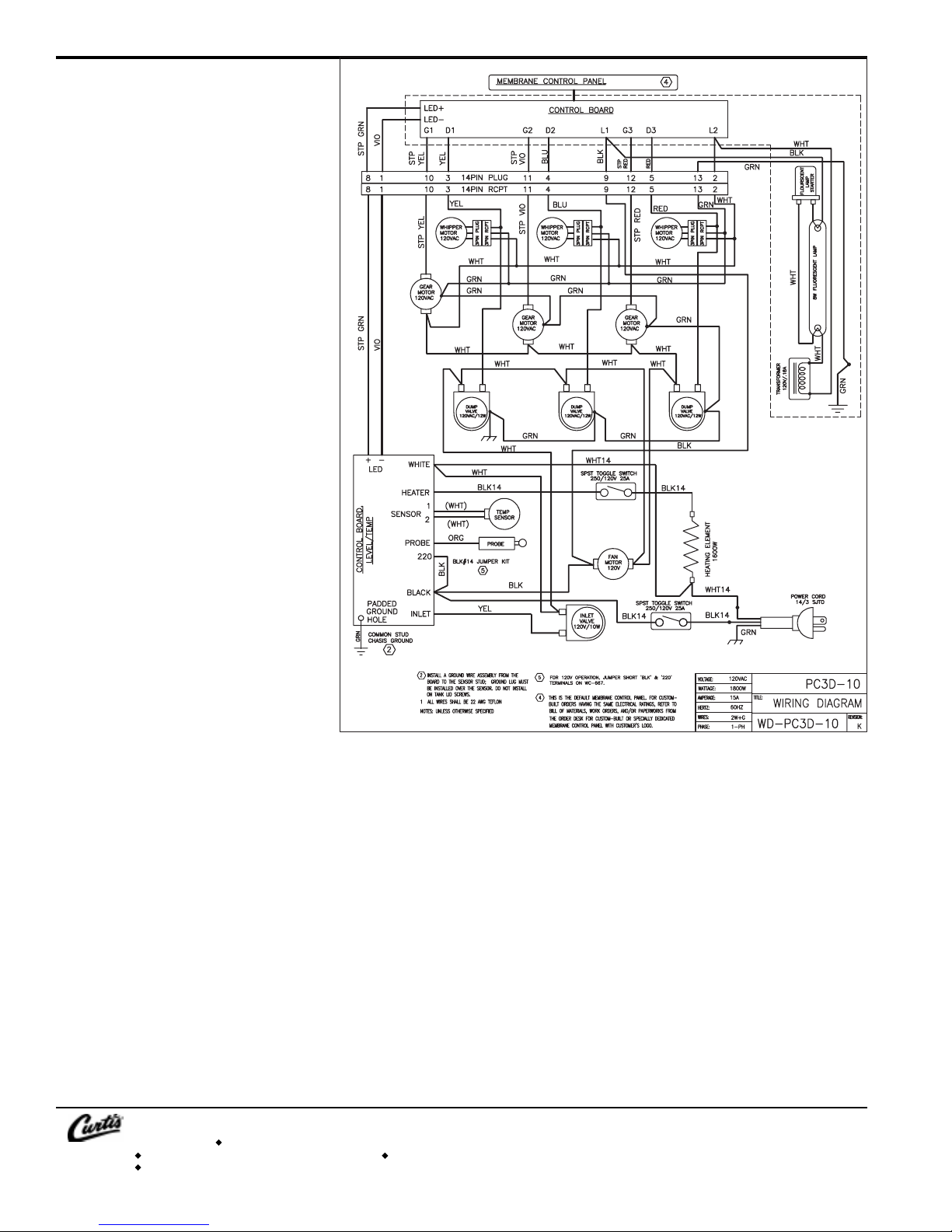
ELECTRICAL SCHEMAELECTRICAL SCHEMA
ELECTRICAL SCHEMA
ELECTRICAL SCHEMAELECTRICAL SCHEMA
PC-3D-10PC-3D-10
PC-3D-10
PC-3D-10PC-3D-10
TICTIC
TIC
TICTIC
WARRANTY We hereby certify that the products manufactured by the Wilbur Curtis Company, Inc., are, to thebest of our knowledge, free from all defects and faulty workmanship.
4
The following warranties and conditions are applicable:
• 90 Days for Labor and 1 Year Parts from Date of Purchase from Factory: This warranty covers all electrical parts, fittings and tubing.
• 40 Months or 40, 000 Pounds of Coffee on a set of Grinding Burrs. (ADS Grinders)
• 2 Years from Date of Purchase: This warranty covers electronic control boards and leaking or pitting of a stainless steel body of a Brewer or Urn.
• 90 Days from Date of Purchase: On replacement parts that have been installed on out of warranty equipment
All in-warranty service calls must have prior authorization from the manufacturer. For an RMA (Return Merchandise Authorization) number, call the Technical Service Department at 1-800-995-0417. The Wilbur Curtis
Company will allow up to 100 miles, round trip, per in-warranty service call.
CONDITIONS & EXCEPTIONS
The warranty covers original equipment at time of purchase only. The Wilbur Curtis Company, Inc., assumes no responsibility for substitute replacement parts installed on Curtis equipment that have not been purchased
from the Wilbur Curtis Company. Inc The Wilbur Curtis Company will not accept any responsibility if the following conditions are not met. The warranty does not cover and is void under these circumstances:
1) Improper operation of equipment. The equipment must be used for its designed and intended purpose and function.
2) Improper installation of equipment. This equipment must be installed by a professional, certified technician and must comply with all local electrical, mechanical and plumbing codes.
3) Wilbur Curtis Company will not be responsible for the operation of equipment at other than the stated voltages on the serial plate.
4) Abuse or neglect (including failure to periodically clean or remove lime accumulations). Manufacturer is not responsible for variation in equipment operation due to excessive lime or local water
conditions.
5) Replacement of items subject to normal use and wear. This shall include, but is not limited to, light bulbs, shear disks, “0” rings, gaskets, canister assemblies. whipper chambers and plates, mixing
bowls, agitation assemblies and whipper propellers.
6) Any faults resulting from inadequate water supply. This includes, but is not limited to, excessive or low water pressure, and inadequate or fluctuating water flow rate.
7) All repairs and/or replacements are subject to our decision that the workmanship or parts were faulty and the defects showed up under normal use.
8) All labor shall be performed during regular working hours. Overtime charges are the responsibility of the owner.
9) Charges incurred by delays, waiting time, or operating restrictions that hinder the service technician’s ability to perform service is the responsibility of the owner of the equipment.
This includes institutional and correctional facilities.
10) All claims under this warranty must be submitted to the Wilbur Curtis Company Technical Service Department before return of the unit to the factory.
11) All equipment returned to us must be repackaged properly in the original carton. No units will be accepted if they are damaged in transit due to improper packaging.
12) Damaged in transit.
13) The resetting of safety thermostats and circuit breakers, programming and temperature adjustments are the responsibility of the equipment owner.
NO UNITS OR PARTS WILL BE ACCEPTED WITHOUT A RETURN MERCHANDISE AUTHORIZATION (RMA). RMA NUMBER MUST BE MARKED ON THE CARTON OR SHIPPING LABEL.
All in-warranty service calls must be performed by an authorized service center, where service is available. Call the factory for location near you.
WILBUR CURTIS CO., INC.
6913 Acco St., Montebello, CA 90640-5403 USA
Phone: 800/421-6150 Fax: 323-837-2410
Technical Support Phone: 800/995-0417 (M-F 5:30A - 4:00P PST) E-Mail: techsupport@wilburcurtis.com
Web Site: www.wilburcurtis.com
Printed in U.S.A. 4/06 F-2067-S Rev A
FOR THE LATEST SPECIFICATION INFORMATION GO TO WWW.WILBURCURTIS.COM
 Loading...