

Page 1
OIL-LESS COMPRESSOR
OPERATION AND INSTRUCTION
MANUAL
OIL-LESS
COMPRESSOR MODELS
OL 512 SINGLE STAGE 3 H.P.
OL 512 SINGLE STAGE 5 H.P.
OL 524 TWO STAGE 5 H.P.
CAP-215
APRIL, 2003
REV. D
OL 812 SINGLE STAGE 7 1/2 H.P.
OL 812 SINGLE STAGE 10 H.P.
CAUTION
Before installing this compressor, read and understand
the safety precautions contained within this manual
1905 Kienlen Avenue, St. Louis, Missouri 63133,
PHONE(314)383-1300 ----- FAX (314)381-1439
CURTIS - TOLEDO, INC.
Page 2

TABLE OF CONTENTS
1.
1.1.
1.2.
1.2.1
1.2.2.
1.3.
1.4.
2.
2.1.
2.2.
3.
3.1.
3.1.1.
3.1.2.
3.2.
3.2.1.
3.2.2.
4.
4.1.
4.2.
4.3.
4.4.
4.5.
4.6.
5.
5.1.
5.2.
6.
6.1.
7.
7.1.
Safety................................................................................................................................................... i
Safety Precautions............................................................................................................................... i,ii
Receiving Delivery............................................................................................................................... iii
Freight Damage.................................................................................................................................... iii
Installation............................................................................................................................................ iii
Electrical Supply Requirements............................................................................................................ iv
Start-up Procedures.............................................................................................................................. iv
Air Inlet Systems.................................................................................................................................. iv,v
Compressed Air Discharge System....................................................................................................... v
System Components............................................................................................................................ vi, vii
Stopping for Maintenance..................................................................................................................... vii
Pulley Alignment and Belt Tensioning................................................................................................... viii
GENERAL................................................................................................................................................. 1
PURPOSE AND SHORT DESCRIPTION.................................................................................................. 1
DESIGN AND MODE OF OPERATION..................................................................................................... 8
DESIGN.................................................................................................................................................... 8
MODE OF OPERATION (1ST STAGE)…....................................................................................................... 8
MODE OF OPERATION (2ND STAGE)……………………………………………………………………………. 9
TECHNICAL DATA................................................................................................................................... 10,11
ELECTRICAL DATA.................................................................................................................................. 12
INTAKE FILTER........................................................................................................................................ 13
DESCRIPTION.......................................................................................................................................... 13
INTAKE FILTER MAINTENANCE............................................................................................................. 13
INTERMEDIATE AND FINAL SEPARATOR.............................................................................................. 14
FUNCTIONAL DESCRIPTION OF INTERMEDIATE SEPARATOR (2-STAGE COMPRESSSOR ONLY). 14
CONDENSATE DRAIN............................................................................................................................. 14
INTERMEDIATE SEPARATOR MAINTENANCE...................................................................................... 14
FUNCTIONAL DESCRIPTION OF FINAL SEPARATOR........................................................................... 15
CONDENSATE DRAIN............................................................................................................................. 15
FINAL SEPARATOR MAINTENANCE....................................................................................................... 15
VALVES.................................................................................................................................................... 16
FUNCTIONAL DESCRIPTION OF 1st STAGE......................................................................................... 16
FUNCTIONAL DESCRIPTION OF 2nd STAGE......................................................................................... 16
INITIAL OPERATIONAL CHECK OF VALVES............................................................................................ 17
GENERAL INSTRUCTIONS FOR CHANGING THE VALVES................................................................... 17
CHANGING THE VALVES OF THE 1st STAGE........................................................................................ 18
CHANGING 2nd STAGE VALVES AND VALVES OF 1st STAGE PRESSURE VALVE............................. 18
AUTOMATIC CONDENSATE DRAIN........................................................................................................ 19
DESCRIPTION.......................................................................................................................................... 19
FUNCTION............................................................................................................................................... 19
COOLING SYSTEM.................................................................................................................................. 20
GENERAL................................................................................................................................................. 21
SAFETY REGULATIONS.......................................................................................................................... 21
GENERAL................................................................................................................................................. 21
Instruction Manual Oil-Less Compressors
Page 3

Instruction Manual Oil-Less Compressors
TABLE OF CONTENTS (CONT’D)
8. INSTALLATION OPERATION................................................................................................................. 23
8.1. INSTALLATION OF THE COMPRESSOR............................................................................................... 23
8.1.1. NATURAL VENTILATION........................................................................................................................ 24
8.1.2. FORCED VENTILATION......................................................................................................................... 25
8.2. ELECTRICAL INSTALLATION................................................................................................................ 26
8.3. OPERATION............................................................................................................................................. 26
8.3.1. PREPARATION FOR OPERATION........................................................................................................... 26
8.3.2. STARTING THE COMPRESSOR.............................................................................................................. 26
8.4. SHUT-DOWN PROCEDURE..................................................................................................................... 26
9. MAINTENANCE SCHEDULE.................................................................................................................... 27
9.1. MAINTENANCE INTERVALS.................................................................................................................... 27
9.2. MAINTENANCE RECORD........................................................................................................................ 27
10. STORAGE, PRESERVATION................................................................................................................... 28
10.1. GENERAL................................................................................................................................................ 28
10.2. PREPARATION......................................................................................................................................... 28
10.3. PREVENTIVE MAINTENANCE DURING STORAGE................................................................................ 28
10.4. REACTIVATING THE COMPRESSOR...................................................................................................... 28
11. REPAIR INSTRUCTIONS......................................................................................................................... 29
11.1. GENERAL................................................................................................................................................. 29
12. TROUBLE-SHOOTING............................................................................................................................. 30
13. TABLES.................................................................................................................................................... 31
13.1. TIGHTENING TORQUE VALUES............................................................................................................. 31
13.2. TORQUE SEQUENCE.............................................................................................................................. 31
13.3. MAINTENANCE SCHEDULE.................................................................................................................... 32,33
TABLE OF FIGURES
Fig. 1 OL 512, REAR VIEW.................................................................................................................................. 2
Fig. 2 OL 512, LEFT SIDE VIEW.......................................................................................................................... 3
Fig. 3 OL 524, REAR VIEW.................................................................................................................................. 4
Fig. 4 OL 524, LEFT SIDE VIEW.......................................................................................................................... 5
Fig. 5 OL 812, REAR VIEW.................................................................................................................................. 6
Fig. 6 OL 812, LEFT SIDE VIEW.......................................................................................................................... 7
Fig. 7 POSITION OF STAGES AT 2-STAGE COMPRESSOR.............................................................................. 8
Fig. 8 FUNCTION OF NON-RETURN VALVE....................................................................................................... 9
Fig. 9 OPERATION CHARACTERISTIC............................................................................................................... 12
Fig. 10 INTAKE FILTER.......................................................................................................................................... 13
Fig. 11 INTERMEDIATE-/FINAL SEPARATOR....................................................................................................... 14
Fig. 12 VALVE OPERATION 1st STAGE................................................................................................................ 16
Fig. 13 VALVE OPERATION 2nd STAGE............................................................................................................... 16
Fig. 14 VALVE HEAD 1st STAGE........................................................................................................................... 18
Fig. 15 VALVE HEAD 2nd STAGE.......................................................................................................................... 18
Fig. 16 INSTALLATION WITH NATURAL VENTILATION....................................................................................... 24
Fig. 17 INSTALLATION WITH FORCED VENTILATION........................................................................................ 25
Fig. 18 TORQUE SEQUENCE................................................................................................................................ 31
Page 4

Instruction Manual Oil-Less Compressors
Fig. 19 2 STAGE COMPRESSOR DIMENSIONS (070308-1015)........................................................................... 33
Fig. 20 1 STAGE COMPRESSOR DIMENSIONS (070307-1015)........................................................................... 35
Fig. 21 1 STAGE COMPRESSOR DIMENSIONS (077734).................................................................................... 36
Fig. 22
Fig. 23
D51.2, DIAGRAM & SPARE PARTS LIST OF CYLINDER, PISTON & INTAKE VALVE …………………..
D52.4, DIAGRAM & SPARE PARTS LIST OF CYLINDER, PISTON & INTAKE VALVE …………………..
37
38
Page 5

Instruction Manual Oil-Less Compressors
INTRODUCTION
THIS MANUAL CONTAINS OPERATION AND MAINTENANCE
SCHEDULES FOR THE OIL-LESS COMPRESSOR MODELS:
OL 512
OL 524
OL 812
ALL INSTRUCTIONS SHOULD BE OBSERVED AND CARRIED
OUT IN THE ORDER LAID DOWN TO PREVENT DAMAGE AND
PREMATURE WEAR TO THE EQUIPMENT AND THE COMPRESSORS
SERVED BY IT.
WHILE EVERY EFFORT IS MADE TO ENSURE THE ACCURACY
OF THE PARTICULARS CONTAINED IN THIS MANUAL, THE
MANUFACTURING COMPANY WILL NOT, UNDER ANY
CIRCUMSTANCES, BE HELD LIABLE FOR ANY INACCURACIES
OR THE CONSEQUENCES THEREOF.
INTRODUCTION
CAP-215
Page 6

CAP-215
Instruction Manual Oil-Less Compressors
SAFETY
At Curtis-Toledo, Inc. safety is a primary concern. Beginning with the design stage, safety is built into every "Curtis Compressor". It is
the purpose of this manual to pass along the "safety first" concept to you by providing safety precautions throughout its pages.
“WARNING!”, "CAUTION!", and "DANGER!" are displayed in large bold capital letters to call attention to areas of vital concern. They
represent different degrees of hazard seriousness, as stated below. The safety precaution is spelled out in bold upper and lower case
letters.
DANGER!
Immediate hazards which result in severe
personal injury or death.
WARNING!
Hazards or unsafe practices that could result In
personal injury or death.
CAUTION!
Hazards or unsafe practices which could result
In minor personal injury, product or property
damage.
Each section of the operating instruction manual, as well as any instructions supplied by manufacturers of supporting equipment, should
be read and understood prior to starting the compressor. If there are any questions regarding any part of the instructions, please call
your local Curtis-Toledo Distributor, or the Curtis-Toledo factory before creating a potentially hazardous situation. Life, limb, or
equipment could be saved with a simple phone call, (314) 383-1300.
SAFETY PRECAUTIONS
The owner, lessor or operator of any compressor unit
manufactured by Curtis-Toledo, Inc. is hereby warned that
failure to observe all safety precautions may result in serious
injury to personnel and/or damage to property.
Curtis-Toledo, Inc. neither states as fact, nor in any way implies
that this list of safety precautions is an all inclusive list, the
observance of which will prevent all damage to property or
injury to personnel.
Every reasonable effort has been taken to ensure that
complete and correct instructions have been included in this
manual. However, possible updates and changes may have
occurred since this printing. Curtis-Toledo, Inc. reserves the
right to change specifications, without incurring any obligation
for equipment previously or subsequently sold.
Compressors and/or units are assembled to comply with the
customer's purchase order and in compliance with CurtisToledo, Inc. specifications; alteration must not be made to the
compressor or unit without Curtis-Toledo written approval.
Provisions must be made by the owner, lessor or operator to
have a pressure reducing regulator valve with air gauge in
each service line to supply safe and proper air pressure for the
various use and applications.
When supplying air pressure direct from air compressor to a
tire chuck for public or operator use to inflate tires and so forth,
a safety precaution sign in large bold print must be posted in
plain view at tire chuck location, "DANGER, AIR PRESSURE
FROM THIS CHUCK MAY EXCEED SAFE PRESSURE FOR
TIRES AND RELATED EQUIPMENT". A hand operated
gauge must be used to measure and not exceed safe inflated
pressure.
i
Page 7

Instruction Manual Oil-Less Compressors
DANGER!
Air used for breathing or food processing must meet
O.S.H.A. 29 C.F.R. 1910.134 or F.D.A. 21 C.F.R. 178.350
regulations. Failure to do so will cause severe injury or
death.
WARNING!
Compressors are precision high speed mechanical
equipment requiring caution in operation to minimize
hazard to property and personnel. There are many
obvious safety rules that must be observed in the
operation of this type of equipment. Listed below (in no
particular order) are some additional safety precautions
that must be observed.
• Transfer of toxic, dangerous, flammable or explosive
substances using Curtis-Toledo products Is at the
User's risk.
• Turn off and lockout/tagout the main power
disconnect switch before attempting to work or
perform any maintenance.
• Do not attempt to service any part of this unit while It
Is running.
• Relieve the system of all pressure before attempting
to service any part of the unit.
• Do not operate the unit with any of its safety guards,
shields, or screens removed.
• Do not remove or paint over any DANGER!,
WARNING!, CAUTION!, or Instructional materials
attached to the compressor. Lack of Information
regarding hazardous conditions can cause property
damage or personal Injury.
• Periodically check all pressure relief valves for proper
operation.
• Do not change the pressure setting of the pressure
relief valve, restrict the function of the pressure relief
valve, or replace the pressure relief valve with a plug.
CAP-215
• Do not install a shutoff valve in the compressor
discharge line without first Installing a pressure relief
valve of proper size and design between the shutoff
valve and the compressor.
• Do not use plastic pipe, rubber hose, or lead-tin
soldered joints In any part of the compressed air
system.
• Alterations must not be made to this compressor
without Curtis-Toledo's approval.
• Be sure that all tools, shipping and Installation debris
have been removed from the compressor and
Installation site prior to starting the compressor.
• Do not operate the compressor in excess of the
A.S.M.E. pressure vessel rating for the receiver or the
service rating of the compressor, whichever is lower.
• Make a general overall inspection of the unit daily and
correct any unsafe situations.
• "Horseplay" of any kind involving compressed air is
dangerous and can cause very serious injury to the
participants.
• Do not touch the compressor during or after
operation-it may be HOT
• Provisions should be made to have the instruction
manual readily available to the operator and
maintenance personnel. If for any reason any part of
the manual becomes illegible or the manual is lost,
have it replaced immediately. The instruction manual
should be read periodically to refresh one's memory.
It may prevent a serious or fatal accident.
• It is recommended sufficient clean-up equipment be
provided and proper maintenance be performed to
ensure clean, dry, oil-free air for instrumentation.
ii
Page 8

Instruction Manual Oil-Less Compressors
RECEIVING DELIVERY
Immediately upon receipt of compressor equipment and prior to
completely uncrating, the following steps should be taken:
1. Inspect compressor equipment for damage that may have
occurred during shipment. If any damage is found, demand an
inspection from the carrier. Ask the carrier how to file a claim
for shipping damages. (Refer to FREIGHT DAMAGE for
complete details.) Shipping damage is not covered by CurtisToledo's compressor warranty.
CAUTION!
Improper lifting can result in component or system damage or
personal Injury. Follow good shop practices and safety
procedures when moving the unit.
2. Ensure that adequate lifting equipment is available for
moving the compressor equipment.
FREIGHT DAMAGE
The transportation industry has adopted a modification with
regard to the handling of obvious and concealed damage
claims. Therefore, it is extremely important that you examine
every carton and crate as soon as you receive it. If there is any
obvious damage to the shipping container, have the delivering
carrier sign the freight bill, noting the apparent damage, and
request a damage report.
INSTALLATION
Curtis-Toledo's air compressors should be installed in an area
that is clean, well lighted, and adequately ventilated.
Inspection and maintenance checks are required daily.
Therefore, sufficient space needs to be provided around the
compressor for safe and proper inspection, cleaning, and
maintenance.
The compressor must not be installed closer than 15 inches to
a wall, or 24 inches to another compressor. This allows ample
circulation of air across the compressor cylinders, heads and
cooler (if so equipped). If at all possible, the pulley drive
system (i.e. motor pulley, compressor pulley, belts and guard)
should be located next to a wall to minimize any danger
created by the drive system while the compressor is operating.
CAP-215
3. Read the compressor nameplate to verify the model
and size ordered.
4. Read the motor nameplate to be sure the motor is
compatible with your electrical conditions (volts, phase, hertz).
5. Read the pressure relief valve nameplate to be sure it does
not exceed the working pressure of the compressor or any
other component in the system.
6. Read and understand the safety precautions contained
within this manual. The successful and efficient operation of
compressor equipment depends largely upon the amount of
care taken to install and maintain the equipment. CurtisToledo
strongly recommends that any or all person(s) in charge of
installing, maintaining, or servicing one of our compressors
read and understand entire contents of this manual and the
respective compressor installation and operating instruction
manual in order to perform such duties safely and efficiently.
If concealed damage is discovered at a later date, the carrier
must be notified within 15 days of initial receipt of freight.
Contact the carrier as soon as possible, giving them an
opportunity to inspect the shipment at the premises where the
delivery was made. Do not move the damaged freight from the
premises where the original delivery was made. Retain all
containers and packing for inspection by the carrier.
Due to standard motor limitations, it is recommended that the
compressor be operated in temperatures under 104° F. In cold
climates, the compressor should be installed in a heated
building.
CAUTION!
Do not operate this compressor in ambient temperatures lower
than -15° F. A crankcase heater is recommended for a
compressor that is to operate In temperatures under 32° F.
WARNING!
Under no circumstances should a compressor be used in an area
that may be exposed to toxic, volatile, or corrosive atmosphere,
Do not store toxic, volatile, or corrosive agents near the
compressor
iii
Page 9

Instruction Manual Oil-Less Compressors
ELECTRICAL SUPPLY REQUIREMENTS
The electrical installation of this unit should be performed by a
qualified electrician with knowledge of the National Electrical
Code (N.E.C.), O.S.H.A. code and/or any local or state codes
having precedence.
Before installation, the electrical supply should be checked for
adequate wire size and transformer capacity. A suitable circuit
breaker or fused disconnect switch should be provided. When
a 3-phase motor is used to drive a compressor, any
unreasonable voltage imbalance between the legs must be
eliminated and any low voltage corrected to prevent excessive
current draw. Note: This unit must be grounded.
The installation, electric motor, wiring, and all electrical controls
must be in accordance with NFPA 70-1 84 National Electric
Code, National Electric Safety Code, state and local codes.
Failure to abide by the national,
state and local codes may
START-UP PROCEDURES
If the compressor is equipped with an automatic start-stop
control (with pressure switch unloading), it is automatically
unloaded upon starting, and will automatically load after
attaining running speed. If the compressor is equipped with a
constant speed control (pilot valve unloading), it is necessary to
manually unload the compressor, if there is pressure in the
discharge line, in order to achieve an unloaded start. The
compressor must be manually loaded after the compressor has
attained full running speed; thereafter, it functions automatically
to maintain operation pressure until the unit is shut off.
AIR INLET SYSTEM
AIR INTAKE
A clean, cool and dry air supply is essential to the satisfactory
operation of your Curtis-Toledo air compressor. The standard
air filter that the compressor is equipped with when leaving the
factory is of sufficient size and design to meet normal
conditions, when properly serviced, in accordance with the
maintenance section of this manual.
CAP-215
result in physical harm and/or property damage. Do not bypass motor overcurrent protection.
DANGER!
High voltage may cause personal injury or death, per
O.S.H.A. regulations 1910.137, disconnect and
lockout/tagout all electrical Dower supplies before
opening the electrical enclosure or servicing.
WARNING!
Never assume a compressor is safe to work on just
because it Is not operating. It could restart at any time.
Follow all safety precautions outlined. NEMA electrical
enclosures and components must be appropriate to the
area Installed.
Close the disconnect switch and start the compressor.
Observe the direction of rotation, which should be
counterclockwise when viewed from the flywheel side of the
compressor on all models. For single-phase units, the
direction of rotation is determined by the motor nameplate
instructions, and is adjusted at the factory. For three-phase
units, if the rotation is incorrect, stop the unit and interchange
any two of the three wires to the motor at the disconnect
switch. This will reverse the direction of rotation of the motor
and compressor .
If, however. the compressor is to be installed in a location
where considerable dust, dirt and other
contaminants are prevalent, consult your Curtis Toledo
Distributor for advice and optional filters. It is the User's
responsibility to provide adequate filtration for those conditions.
Oil bath filters are not to be used. Warranty will be void if a
failure is determined to be caused by inadequate filtration.
iv
Page 10
Instruction Manual Oil-Less Compressors
REMOTE INLET FILTERS
Depending on the size of the compressor and the size and
construction of the room in which the unit operates, the air inlet
may have to be located outside of the room. If it is necessary
to remotely install the air filter, make the inlet piping as short
and direct as possible. Remotely installed air filters can lead to
vibrations in the inlet piping. These vibrations can be
minimized by adding a pulsation dampener in the inlet piping
between the remote inlet filter(s) and the compressor.
If the Intake is piped to outside atmosphere, a hooded filter
should be installed to prevent water or snow from being
ingested into the compressor.
COMPRESSED AIR DISCHARGE SYSTEM
CAP-215
All inlet piping should be at least the same size (or larger) in
diameter as the inlet connection to the compressor. For every
10 feet of inlet piping or every 900 bend, increase the inlet
piping diameter by one pipe size. The inlet piping must be
thoroughly clean inside. Remove all weld slag, rust or dirt.
Galvanized pipe with threaded or flanged fittings is preferred.
CAUTION!
Never locate the compressor air inlet system where toxic,
volatile or corrosive vapors, air temperatures exceeding
104°F., water, or extremely dirty air could be ingested. These
types of atmospheres could adversely affect the performance
of the compressor system.
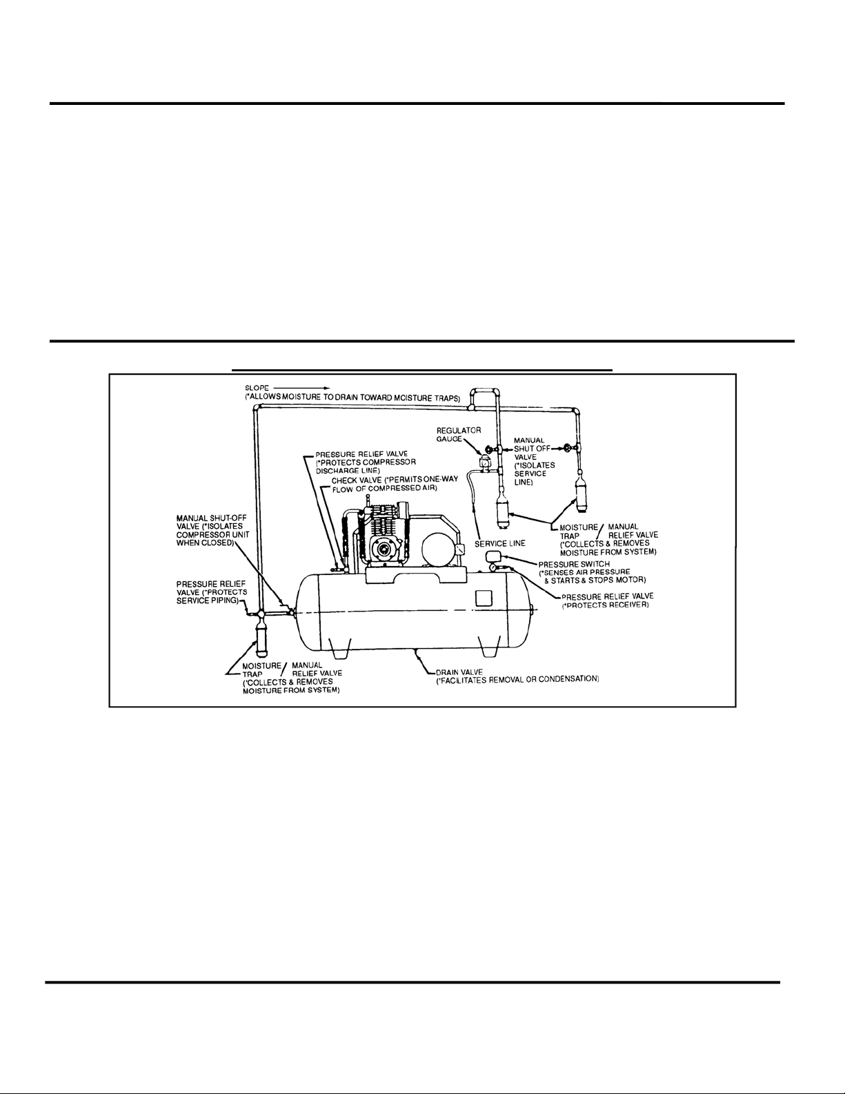
Typical Drop Leg & Component Location
The discharge piping should be of the same diameter as the
compressor discharge connection, or sized so that the
pressure drop at any point in the system does not exceed 10%
of the air receiver pressure. Install auxiliary air receivers near
heavy loads or at the far end of a Iong system. This will insure
sufficient pressure if the use is intermittent, or sudden large
demands are placed on the system.
Discharge piping should slope to a drop leg (refer to TYPICAL
DROP LEG & COMPONENT LOCATION) or moisture trap to
provide a collection point where moisture can be easily
removed. All service line outlets should be installed above the
moisture traps to prevent moisture from entering the tool or
device using the air. Manual
shutoff valves, protected by
pressure relief valves, should be installed at all service
line outlets to eliminate leakage while the tools are not in use.
As with any piping, all parts of the discharge piping should fit so
as not to create any stress between the piping and
components.
WARNING!
Never join pipes or fittings with lead-tin soldering. Welded or
threaded steel pipes and cast iron fittings, designed for the
pressures and temperatures, are recommended.
v
Page 11
Instruction Manual Oil-Less Compressors
SYSTEM COMPONENTS
Efficiency and safety are the primary concerns when selecting
components for compressed air systems. Products of inferior
quality can not only hinder performance of the unit, but could
cause system failures that result in bodily harm or even death.
Select only top quality components for your system. Call your
local Curtis-Toledo Distributor for quality parts and professional
advise.
DRIVE PULLEYS
Drive pulleys must be properly aligned and drive belt tension
set to specifications (refer to PULLEY ALIGNMENT & BELT
TENSION). Improper pulley alignment and belt tension can
cause motor overloading, excessive vibration, and premature
belt and/or bearing failure.
DANGER!
Excessive compressor RPM's (speed) could cause a pulley to
burst. In an Instant, the pulley could separate Into fragments
capable of penetrating the belt guard and causing bodily harm
or death. Do not operate the compressor above the
recommended RPM.
GUARDS
All mechanical action or motion is hazardous in varying
degrees and needs to be guarded. Guards should be designed
to achieve the required degree of protection and still allow full
air flow from the compressor sheave across the unit. Guards
shall be in compliance with OSHA safety and health standards
29 CFR 1910.219 in OSHA manual 2206 and any state or local
codes.
WARNING!
Guards must be fastened in place before starting the
compressor and never removed before cutting off and locking
out the main power supply.
CHECK VALVES
Check valves are designed to prevent back-flow of air pressure
in the compressed air system (air flows freely in one direction
only). The check valve must be properly sized for air flow and
temperature. Do not rely upon a check valve to isolate a
compressor from a pressurized tank or compressed air delivery
system during maintenance procedures!
MANUAL SHUTOFF VALVES
Manual shutoff valves block the flow of air pressure in either
direction. This type of valve can be used to isolate a
compressor from pressurized system, provided the system is
equipped with a pressure relief valve capable of being
manually released. The pressure relief valve should be
CAP-215
installed between the manual shutoff valve and the
compressor.
PRESSURE RELIEF VALVES
Pressure relief valves aid in preventing system failures by
relieving system pressure when compressed air reaches a
determined level. They are available in various pressure
settings to accommodate a range of applications. A check
valve and pressure relief valve are required in all compressor
discharge lines. Pressure relief valves are preset by the
manufacturer and under no circumstances should the setting
be changed by anyone other than the manufacturer.
DANGER!
Pressure relief valves are designed to protect compressed air
systems in accordance with ASME B19 safety standards.
Failure to provide properly sized pressure relief valves may
cause property damage, severe personal injury or even death.
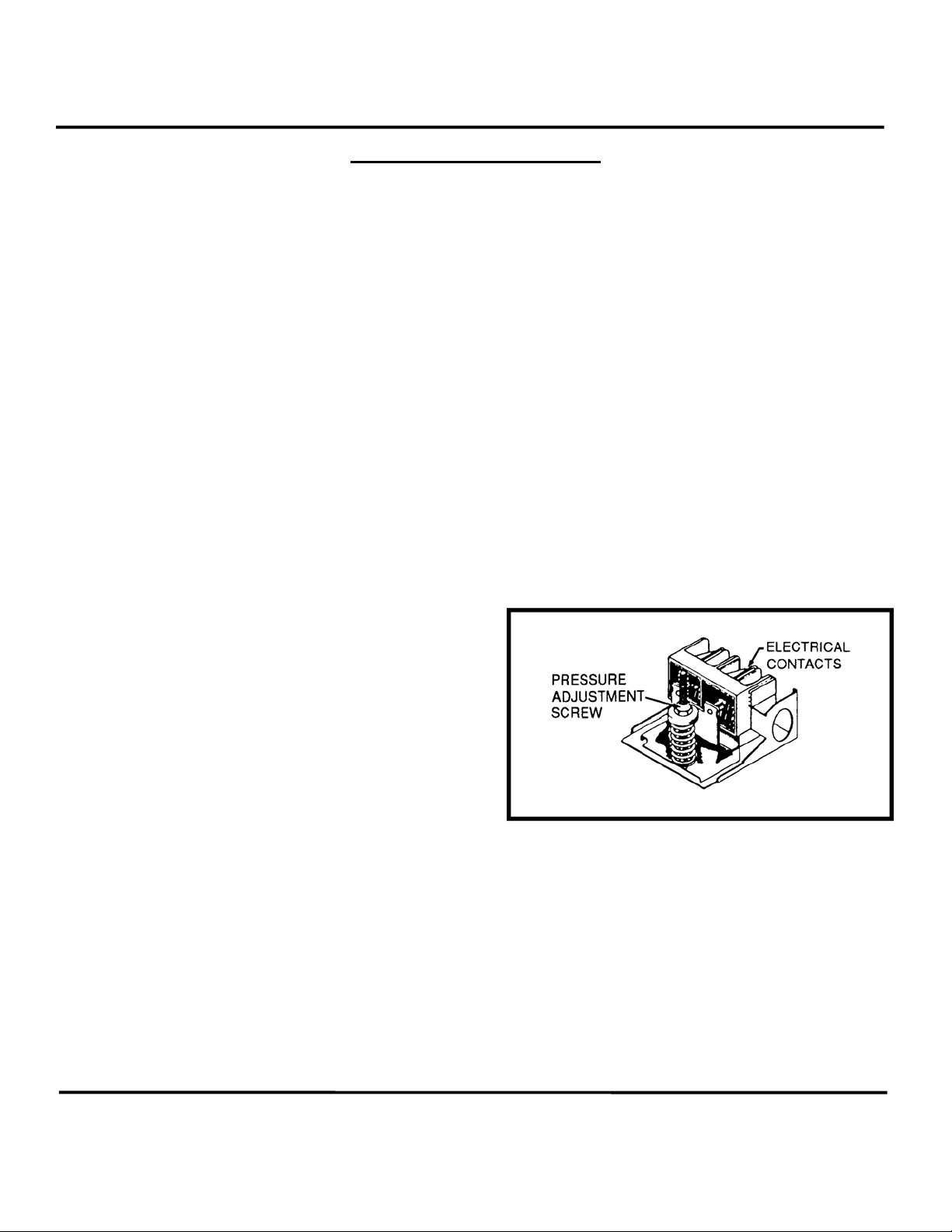
PRESSURE SWITCH
The pressure switch detects the demand for compressed air
and allows the motor to start. When the demand is satisfied,
the unit stops. Pressure switches provided by Curtis-Toledo
are pre-set at the factory and usually do not require
adjustment. However, it adjustment is required (by qualified
electrician) refer to instructions inside cover of switch housing,
WARNING!
The maximum discharge pressure for the various models
are established by the Curtis performance data. Do not
set the pressure switch or regulators to exceed the design
limit.
WARNING!
Electric power always exists Inside the pressure switch
whenever the compressor package is connected to a
power supply. Be careful not to touch any electrical leads
when setting the pressure switch.
vi
Page 12

Instruction Manual Oil-Less Compressors
SYSTEM COMPONENTS (CONTINUED)
WARNING!
Never exceed the designed pressure for the system or
overload the motor beyond its Maximum Amp Draw.
• Full Load Amps x Service Factor = Max-imum Amp
Draw.
• Full Load Amps (FLA) & Service Factor can normally
be found on motor nameplate.
STOPPING FOR MAINTENANCE
The following procedures should be followed when stopping the
compressor for maintenance or service.
WARNING!
Never assume a compressor Is safe to work on just because It
Is not operating. It could start at any time.
1. Per O.S.H.A. regulation 1910.147: The Control of
Hazardous Energy Source (Lockout/Tagout), disconnect and
lockout the main power source. Display a sign in clear view at
the main power switch that the compressor is being serviced.
2. Isolate the compressor from the compressed air supply by
closing a manual shutoff valveupstream and downstream from
WARNING!
Never assume a compressor is safe to work on just
because it is not operating. It may be in the automatic
stand-by mode and may restart any time. Follow all safety
precautions outlined in STOPPING FOR MAINTENANCE.
the compressor. Display a sign in clear view at the shutoff
valve stating that the compressor is being serviced.
3. Lock open a pressure relief valve within the pressurized
system to allow the system to be completely de-pressurized.
NEVER remove a plug to relieve the pressure!
4. Open all manual drain valves within the area to be serviced.
5. Wait for the unit to cool before starting to service.
(Temperatures of 125°F can burn skin. Some surface
temperatures exceed 350°F when the compressor is
operating.)
CAP-215
vii
Page 13
CAP-215
Instruction Manual Oil-Less Compressors
PULLEY ALIGNMENT & BELT TENSION
Setting Belt Tension
Improper pulley alignment and belt tension are causes for
motor overloading, excessive vibration and premature belt
and/or bearing failure. To prevent this from happening, check
the pulley alignment and belt tension on a regular basis.
At this time, inspect both the motor and compressor pulleys for
oil, grease, nicks or burrs. Clean or replace pulleys if
necessary. Make sure the pulleys are securely fastened. Align
the compressor pulley with the motor or engine pulley. Drive
belt grooves of both pulleys should be in line with each-other.
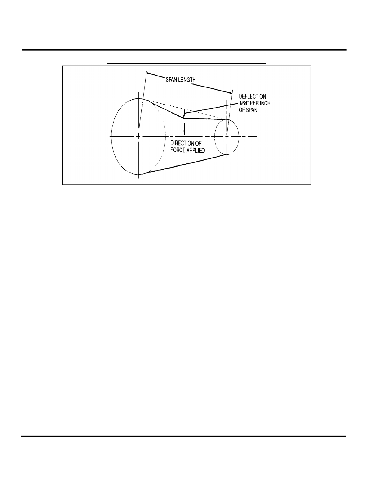
Belt tension should be measured and adjusted to provide
smooth operation. Step-by-step procedures are provided here
to correctly measure and set the drive belt tension:
1. Measure the span length of the drive. (Refer to
MAINTENANCE SCHEDULE.) See instructions in the
respective model manual.
2. Determine the amount of deflection (in inches) required to
measure deflection force (in pounds) by multiplying the span
length x 1/64 (i.e. 32" span length x 1/64 = 1/2" of deflection
required to measure deflection force).
3. Lay a straightedge across the top outer surface of a drive
belt from pulley to pulley.
4. At the center of the span, perpendicular to the belt, apply
pressure to the outer surface of the belt with a belt tension
gauge. Force the belt to the predetermined deflection (refer to
Step 2). Record the reading on the belt tension gauge and
compare to the chart. The deflection force reading should be
within the minimum and maximum values shown. Adjust
belt(s) accordingly. A new belt (or new belt set) should be
initially tensioned 1/3 greater than the maximum valve.
5. Recheck the tension of the new belts several times in the
first 50 hours of operation and adjust if necessary. Thereafter,
check belt tension on a regular basis.
viii
Page 14

CAP-215
Instruction Manual Oil-Less Compressors
1. GENERAL
1.1. PURPOSE AND SHORT DESCRIPTION
The 1-stage oil-less compressor model OL 512, and OL 812, as well as the 2-stage oil-less compressor model
OL 524, are used to compress air in the pressure ranges up to 110 psi (1-stage compressor models) to 220 psi
(2-stage compressor models)
All compressors operate with three cylinders and are air-cooled (Fig. 1 to Fig. 4). The cylinders are set in
Y- configuration, allowing for a small compact design.
A special feature of these models are that they operate without any oil in the crankcase. This is the result of the
following construction characteristics:
- friction treated surface of the cylinders
- PTFE (polytetrafluoride ethylene) compound coated piston guiding surfaces
- piston rings made exclusively from special PTFE compound.
These compressor models need very little maintenance because of their oil-less operation, therefore an oil
change or a special condensate disposal is not necessary.
The outstanding characteristic of this compressor model is their long life which is the result of
- low friction and low wear of cylinders and pistons
- the corrosion resistant material used for all parts coming into contact with the air stream
- optimal cooling of all moving parts (air intake through crankcase).
The oil-less compressor standard equipment:
- After-cooler for each cylinder and each manifold
- Air filter maintenance indicator
1
Page 15
CAP-215
Instruction Manual Oil-Less Compressors
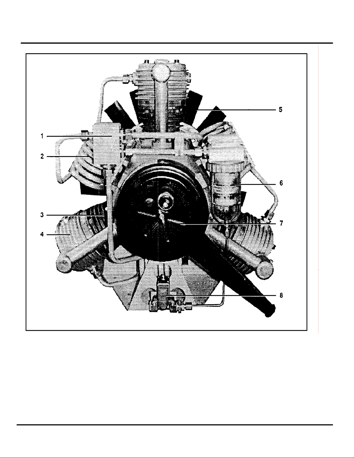
Fig. 1: OL 512 (single stage), rear view
1 Cooler Manifold
2 After-cooler
3 Cylinder 1st stage
4 Valve head 1st stage
5 Fan/flywheel
6 Final Separator (optional)
7 Intake filter
8 Condensate drain valve (optional with #6)
2
Page 16
CAP-215
Instruction Manual Oil-Less Compressors
Fig. 2: OL 512 (single stage), left side view
1 Cooler Manifold
2 After-cooler
3 Final Separator (optional)
4 Intake filter
5 Valve Head
6 Fan/flywheel
3
Page 17

CAP-215
Instruction Manual Oil-Less Compressors
Fig. 3: OL 524 (2-stage), rear view
1 Valve head 2nd stage
2 Safety valve 1st stage
3 Intermediate cooler
4 Manifold 2nd stage
5 Cylinder 1st stage
6 Valve head 1st stage
7 Intermediate separator
8 Fan/flywheel
9 Intermediate cooler
10 Manifold 1st stage
11 Final separator
12 Maintenance indicator
13 Valve head 1st stage
14 Intake filter
15 Condensate drain valve
4
Page 18

CAP-215
Instruction Manual Oil-Less Compressors
Fig. 4: OL 524 (2-stage), left side view
1 Final separator
2 Manifold
3 After-cooler
4 Intermediate separator (option)
5 Intake filter
6 Valve head 2nd stage
7 Cylinder 2nd stage
8 Fan/flywheel
9 Cylinder 1st stage
10 Vale head 1st stage
5
Page 19

CAP-215
Instruction Manual Oil-Less Compressors
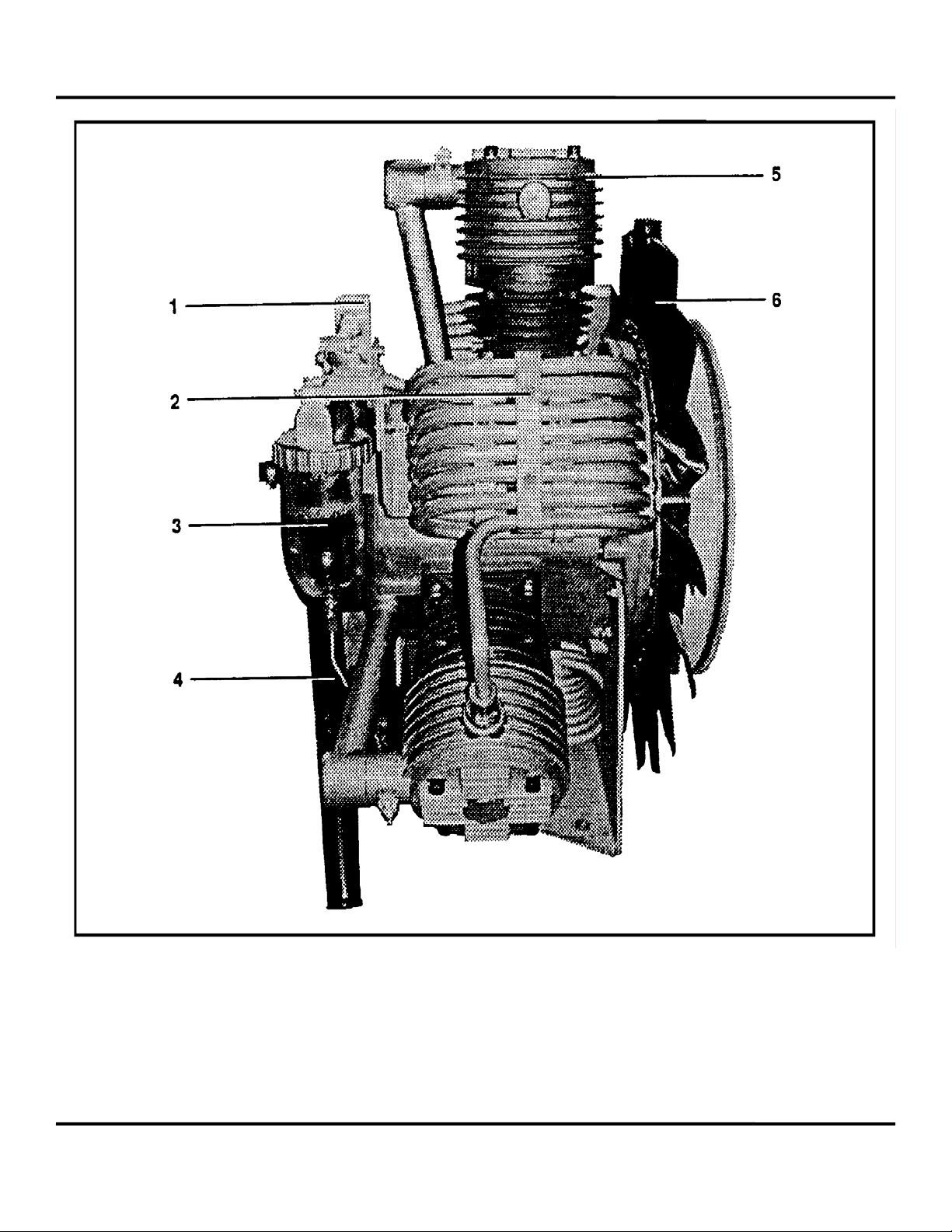
Fig. 5: OL 812 (single stage), rear view
1 Cylinder 1st stage
2 After-cooler
3 Intake filter
a) position of automatic condensate drain (optional)
4 Ventilator/flywheel
5 Final separator
6 Maintenance indicator
6
Page 20

CAP-215
Instruction Manual Oil-Less Compressors
Fig. 6: OL 812 (single stage), left side view
1 Cooler manifold
2 After-cooler
3 Final separator
7
Page 21

Instruction Manual Oil-Less Compressors
1.2. DESIGN AND MODE OF OPERATION
1.2.1 DESIGN
The design of the oil-less compressor is
shown in Fig. 1 to Fig. 4. For drawings
refer to the annex of this manual.
CAP-215
Fig. 7: Position of stages at 2-stage
compressor
1.2.2. Mode of Operation
1-stage compressor
The positions stated refer to Fig. 1.
The outside air is drawn in through the three first stages (3) of the oil-less compressor via intake filter, crankcase and
piston and compressed to a final pressure of max. 110 psi
a)
. The compressed air is cooled back to the original
temperature in the after-coolers (2) and is then lead to a manifold (1). After that it reaches the final separator (6), where
the condensate is filtered out. The condensate is drained regularly by the automatic condensate drain (8)(option)
8
Page 22

CAP-215
Instruction Manual Oil-Less Compressors
2-stage compressor
The position stated refer to Fig. 3.
The two first stages (5) of the oil-less compressor draw in the outside air via the intake filter (14) and the crankcase and
compressed to an intermediate pressure of approx. 60 to 70 psi. The compressed air is cooled back to the original
temperature in the intermediate coolers (3) and is then lead to a manifold (10). The intermediate pressure safety valve (2)
mounted at this manifold is adjusted to a pressure of 120 psi. The condensate is filtered out in the intermediate separator
(7) and is lead to the condensate drain valve (15)(option),The 2nd stage compresses the air now to a final pressure of
max. 210 psi. (Dependent on adjusted operation pressure).
A non-return valve (Fig. 6) is built into the condensate
drain line of the intermediate separator.
It prevents an equalization of pressure between
1st and 2nd stage during the condensate drain.
After opening the solenoid valve the separator of
the 2nd stage is drained. The separator of the 1st
stage is drained after an equalization of pressure
between 1st and 2nd stage.
Fig 8: Function of non-return valve
9
Page 23

Instruction Manual Oil-Less Compressors
1.3. TECHNICAL DATA
1 -stage compressor
No. of stages
Intake volume
b)
Intake pressure
Delivery
Operating pressure, max.
No. of cylinders
Cylinder bore
Piston stroke
Speed
Weight
Drive input
c)
Compressor rotation
Min./max. ambient temperature
2-stage compressor
No. of stages
Intake volume
d)
Intake pressure
Delivery
Operating pressure max.
No. of cylinders
Cylinder bore 1st stage
Cylinder bore 2nd stage
Adjustment of intermediate pressure safety valve
Piston stroke
Speed
Weight
Drive input
e)
Compressor rotation
Min./max. ambient temperature
a) dependent on adjusted operating pressure
b) at max. speed 960 min.
c) at 960 min.
-1
(rpm) and max. final pressure
d) at max. speed 1,060 min.
e) at 1,060 min.-1 (rpm) and max. final pressure
f) at max. speed 1,000 min.
g) at 1,000 min.
-1
(rpm) and max. final pressure
-1
(rpm)
-1
(rpm)
-1
(rpm)
Subject to change without prior notice
10
CAP-215
OL 512
1
31.8 cfm
atmospherical
17 cfm at 110 psi
110 psi
3
3.3 inches
2 inches
960 min.-1 (rpm)
121 lbs.
5.51 H.P.
counterclockwise
facing flywheel
+40...+105Fº
OL 524
2
21.2 cfm
atmospherical
12 cfm at 210 psi
240 psi
3
3.3 inches
1.8 inches
43 psi
2 inches
1,060 min.-1 (rpm)
132 lbs
5.71 H.P.
counterclockwise
facing flywheel
+40 .. +105ºF
Page 24

Instruction Manual Oil-Less Compressors
Technical Data
1 -stage compressor
No. of stages
Intake volume
Intake pressure
Delivery
Operating pressure, max.
No. of cylinders
Cylinder bore
Piston stroke
Speed
Weight
Drive input
Compressor rotation
Min./max. ambient temperature
Subject to change without prior notice
f)
g)
OL 812
1
48 cfm
atmospherical
31.6 cfm at 110 psi
110 psi
3
3.3 inches
3.1 inches
1,000 min.
-1
(rpm)
132 lbs.
10 H.P.
counterclockwise
facing flywheel
+40...+105Fº
CAP-215
11
Page 25

Instruction Manual Oil-Less Compressors
1.4. ELECTRICAL DATA
Electrical Intake filter control
Operating voltage max.
Electrical power consumption
Temperature sensor (option)
Operating voltage max. U
max
Nominal response temperature NAT
Tolerance
Cold resistance
PTC resistance (UKI=2.5 V)
PTC resistance temperature NAT-T
PTC resistance (UKI=2.5 V)
at PTC resistance temperature NAT+T
PTC resistance (UKI=7.5 V)
at PTC resistance temperature NAT+15ºC
Isolation strength U
is
Operating temperature max.
Color code
Operation characteristic PTC temperature sensor
PTC resistance as function of the PTC resistor temperature
Fig. 9: Operation characteristics
Subject to change without prior notice
24V
6W
25V
+130ºC (266ºF)
± 5ºC (9ºF)
100 Ω
550 Ω
1330 Ω
K 4
2.5 kV
175ºC (347ºF)
blue/blue
CAP-215
12
Page 26

CAP-215
Instruction Manual Oil-Less Compressors
2. INTAKE FILTER
2.1. DESCRIPTION
A dry micronic filter is used to filter intake air (Fig. 8). The intake filter is equipped with a replaceable filter cartridge.
2.2. INTAKE FILTER MAINTENANCE
The filter cartridge must be serviced at regular intervals according to maintenance schedule in chapter 9.
For this purpose an optical maintenance indicator is mounted on the intake filter (Fig. 8) and an electrical maintenance
indicator is mounted on the crankcase. They indicate contamination of the filter cartridge and the necessity to clean or
change it. The maintenance indicator reacts at a vacuum of 1.5 in. Hg.
Fig. 10: Intake filter
1 Wing nut
2 Filter housing
3 Filter cartridge
4 Electrical maintenance indicator (crankcase)
5 Optical maintenance indicator (option) – CCC1626
6 Bracket
Clean filter element as follows:
- Remove wing nut (1).
- Remove filter housing (2) from crankcase.
- Remove micronic filter element (3) and clean dry with brush or by blowing air from inside out. Never clean wet! Turn filter element
60º when replacing it.
-
Use recommended spare element VGB 596 only.
Clean filter housing inside using a damp cloth. Take care to prevent dust from entering the crankcase
-
13
Page 27

CAP-215
Instruction Manual Oil-Less Compressors
3. INTERMEDIATE AND FINAL SEPARATOR
3.1. FUNCTIONAL DESCRIPTION OF INTERMEDIATE SEPARATOR (2-STAGE MODELS ONLY)
The intermediate separator (Fig. 9) is mounted after the two first stages of the 2-stage oil-less compressor. The
separator is designed to remove excess water which results from the cooling down after the compressing process
and thus to provide the next stage with a cleaned medium. Separation is achieved by means of a baffle (4). A
sintered metal filter (2) is provided additionally to remove dirt contamination.
3.1.1. CONDENSATE DRAIN
The condensate has to be drained manually as soon as "max." mark is reached, or after each operation.
Therefore open knurled nut mounted on the lower part of separator housing. After draining the condensate,
firmly tighten knurled nut.
Compressors which are equipped with a condensate drain valve are drained automatically. Ensure that the
separators are drained every 15 minutes. At increased humidity, intervals for draining may be shorter.
3.1.2. INTERMEDIATE SEPARATOR MAINTENANCE
Proper operation of individual stages will rely on the intermediate filter being properly serviced.
The sintered filter element of the intermediate
separator is to be cleaned approx. every 4,000
operating hours.
- Remove condensate drain piping from filter.
Unscrew union nut and remove filter cartridge.
- Remove center screw (1), and separate
sintered filter element (2).
- To clean filter element, the best method is to
use hot soapy water and to blow dry with
compressed air.
- On reinstallation of filter elements take care to
observe correct order.
Fig. 11: Intermediate -/final separator
14
Page 28

CAP-215
Instruction Manual Oil-Less Compressors
3.2. FUNCTIONAL DESCRIPTION OF FINAL SEPARATOR
A final separator is mounted after the three first stages of the single-stage oil-less compressor and after the
second stage of the 2-stage oil-less compressor.
Separation is achieved by means of centrifugal action provided by a baffle (4). A sintered metal filter (2) is
provided additionally to remove dirt contamination.
3.2.1. CONDENSATE DRAIN
The condensate has to be drained manually every 15 minutes during operation and after each operation. At
increased humidity, intervals for draining may be shorter. Therefore open knurled nut mounted on lower part of
separator housing. After draining the condensate, firmly tighten knurled nut.
Compressors equipped with a condensate drain valve are drained automatically. Ensure that the filters are
drained every 15 minutes. At increased humidity, intervals for draining may be shorter.
The condensate has to be drained manually every 15 minutes during operation and after each operation. At
increased humidity, intervals for draining may be shorter. Therefore open knurled nut mounted at the lower part
of separator housing. After draining the condensate, firmly tighten knurled nut.
Compressors which are equipped with a condensate drain valve are drained automatically. Ensure that the filters
are drained every 15 minutes. At increased humidity, intervals for draining may be shorter.
3.2.2. FINAL SEPARATOR MAINTENANCE
Maintenance process is the same as for intermediate separator, see chapter 3.1.2.
1-stage compressor (option)
2-stage compressor (std.)
15
Page 29

Instruction Manual Oil-Less Compressors
4. VALVES
4.1. FUNCTIONAL DESCRIPTION OF 1
The valve head of the first stage forms the top part
of the cylinder. The intake valve is fitted on the top
of the piston. The pressure valve is mounted between
valve head and cylinder.
Note that the valves are operated by the flow of
the air. On the suction stroke, the intake
valves open and the air flows into the cylinders.
At the start of the compression stroke the intake
valve closes and the air opens the pressure valve,
see Fig. 10.
Fig. 12: Valve operation 1st stage
4.2. FUNCTIONAL DESCRIPTION OF 2
The intake valve is fitted between valve head and
cylinder.
On the suction stroke, the intake valves open and
the air flows into the cylinders. At the start of the
compression stroke the intake valve closes and the
air opens the pressure valve, see Fig. 11.
st
STAGE
nd
STAGE
CAP-215
Figure 13: Valve operation 2nd stage
16
Page 30

CAP-215
Instruction Manual Oil-Less Compressors
4.3. INITIAL OPERATIONAL CHECK OF VALVES
If the intake pipe to the valve head of the second stage heats up excessively, and the first stage safety valve
relieves, either the intake valve of the second stage or the pressure valve of the first stage is malfunctioning. It
is therefore necessary to remove the valve head and to check and clean these valves, or to replace them as
necessary.
4.4. GENERAL INSTRUCTIONS FOR CHANGING THE VALVES
- Carefully clean dirty valves. Never use a sharp tool for this purpose. Soak the valves in hot soap suds and
clean with soft brush.
- Check individual components for excessive wear. If the valve seat and valve disks are dented, replace
the valves.
- Valve head screws must be tightened with a torque wrench (see tightening torque values chapter 13).
- Check the valve space in the valve heads for dirt and clean, if necessary.
- Use only satisfactory gaskets and 0-rings on reassembly.
- Observe the correct sequence when fitting together again.
- After finishing all maintenance work on the valves, turn the compressor manually using the flywheel and check
whether all items have been correctly installed.
- 30 minutes after restarting the compressor unit after valve maintenance stop unit, let it cool down to ambient
temperature and retighten valve studs and cap nuts. Otherwise valves could work loose due to setting of the
gaskets.
- Remove and check the valves every 7,000 operating hours, if necessary replace them.
17
Page 31

Instruction Manual Oil-Less Compressors
4.5. CHANGING THE VALVES OF THE 1ST STAGE
The intake valve of the 1st stage is integrated into the top part of the piston. The pressure valve is fitted
between valve head and cylinder.
Changing the pressure valve
Change pressure valve of 1st stage according to
chapter 4.6.
Changing the Intake valve
- Loosen two cap nuts from tube connectors
and remove inter-cooler and after-cooler.
- Remove counter-sunk screw (1) together with
fixation nut (2) from piston head.
- Remove plate valve (3).
CAP-215
Fig. 14: valve head 1st stage
4.6. CHANGING 2
ND
STAGE VALVES AND VALVES OF 1ST STAGE PRESSURE VALVE
Intake and pressure valves of the 2nd stage are
combined in one plate valve under the valve
head.
- Loosen two cap nuts from tube connectors
and remove inter-cooler and after-cooler.
- Remove four allen screws (5), together with
washer (6) from valve head (1). Remove valve
head.
- Remove gasket (2) and plate valve (3).
- When reinstalling valve check for right position.
Countersunk screw heads have to be at the top.
Fig. 15: valve head 2nd stage
18
Page 32

CAP-215
Instruction Manual Oil-Less Compressors
5. AUTOMATIC CONDENSATE DRAIN
5.1. DESCRIPTION
The condensate drain valve should drain the final separator (1 -stage compressor) or the intermediate and final
separator (2-stage compressor) every 15 minutes or earlier if necessary.
Furthermore, condensate is drained after each operation (stand still drainage).
A solenoid valve is installed as a condensate drain valve, which is open when it does not receive any
power. It works electro-pneumatically.
5.2. FUNCTION
The solenoid valve closes as soon as it receives current, thus condensate can be collected in the separators.
Power supply is interrupted every 15 minutes, the solenoid valve opens and condensate can be drained.
The solenoid valve is de-energized and opens after the compressor has been shut down. Thus the separators
are drained at down-time.
19
Page 33

CAP-215
Instruction Manual Oil-Less Compressors
6. COOLING SYSTEM
6.1. GENERAL
Cooling of the oil-less compressor is twice as efficient because of their mode of operation:
The compressor is equipped with a flywheel which draws the cooling air through the flywheel cover from the
surroundings and thus cools the cylinder, both intercoolers and the after-cooler. The fan blades are mounted on
the flywheel and are powered by the driving motor.
Additional cooling of all mechanic parts such as crankcase, connecting rods and pistons is effected by drawing
the air in, which has to be compressed for the first stages, via the crankcase.
Refer to chapter 8 for proper installation and cooling air supply.
20
Page 34

Instruction Manual Oil-Less Compressors
7. SAFETY REGULATIONS
7.1. GENERAL
CAP-215
21
Page 35

CAP-215
Instruction Manual Oil-Less Compressors
22
Page 36

Instruction Manual Oil-Less Compressors
8. INSTALLATION OPERATION
8.1. INSTALLATION OF THE COMPRESSOR
CAP-215
Remove all plastic protective plugs and caps before Installing compressor.
The oil-less compressor should be installed so that there is no vibration, e.g. from the drive motor.
- If possible install compressor in such a manner that the compressor fan can get fresh air from outside, for
instance through an opening in the wall.
- Ensure that an adequate exhaust air opening is provided (see Fig. 16).
- When locating the compressor in rooms of less than 39.2 cu. yd. space where natural ventilation is not
ensured, measures must be taken to provide artificial ventilation (this also applies when other systems having
high radiation are operating in the same room (see Fig. 17).
Artificial ventilation is effected by installation of a fan in the exhaust air opening.
23
Page 37

CAP-215
Instruction Manual Oil-Less Compressors
8.1.1. Natural ventilation
As warm air rises, adequate wall openings should be provided for cooling air intake (next to the floor) and for
cooling air outlet (next to/ in the ceiling).
The compressor should be positioned right next to the air inlet opening.
Fig. 16: Installation with natural ventilation
A Minimum distance from wall, intake side 1.6405 ft.
B Minimum distance from wall, exhaust air side 2.46075 ft
The opening for intake air A2 should be approx. 20% larger than the opening for exhaust air A3 taking into
account louvers, grills, etc.
The table in Fig. 16 is based on the following values:
Room temperature 87°F
Temperature variation with natural ventilation 27°F
Thickness of walls 9.8425 in.
If it is not possible to follow the recommended guide lines for natural ventilation (e.g. installation of several
compressors within a very small operating room), the operating room must be ventilated artificially.
24
Page 38

CAP-215
Instruction Manual Oil-Less Compressors
8.1.2. Forced ventilation
Forced ventilation facilitates a reduced variation in temperature. It is achieved, for example by using an exhaust
air fan. The following information is to determine the size of the exhaust air fan:
V = required cooling air stream in ft
p = ∆p = resistance in pa.
It is determined by the shape of the fan and the opening for intake and outlet air together with the channels
connected to them (if any). For simple openings without unfavorable channels approx. p = 100 pa can be used.
Example: For a 10 HP unit, a fan is required which delivers 1177 cfm against 100 pa resistance.
Cooling air fan (∆p and V1)
3
/h for a drop in temperature of 18°F
Fig. 17: Installation with forced ventilation
A Minimum distance from wall, intake side 1.6405 ft.
B Minimum distance from wall, exhaust air side 2.46075 ft
The value stated is only valid for small rooms without considering the warmth emitted by the exterior walls.
Preferably an intake air velocity of 591 ft/min. should be used.
To avoid frost damage due to a very high internal condensate formation, the room temperature should not drop
below +41º F. We recommend that you provide the intake air openings with adjustable louvers to equalize
fluctuation in temperature caused by season change.
The basis for the measurement of required intake and outlet air openings and fans is the VDMA standard
4363 "Ventilation of operation rooms with air cooled compressors".
25
Page 39

CAP-215
Instruction Manual Oil-Less Compressors
8.2. ELECTRICAL INSTALLATION
For installation of electrical equipment attend to the following:
Follow the National Electric Code or local Electric code in providing, fusing, and disconnect switches.
Check electrical supply for voltage, phase, and frequency to see that they match the nameplate stampings on the
motor, magnetic starter solenoids, and other control devices.
Ensure correct installation is carried out only by qualified personnel only.
Immediately after start-up, check direction of rotation with arrow on unit.
8.3. OPERATION
8.3.1. Preparation for operation
All compressors are tested prior to delivery to the customer, so after correct installation, there should be no
problem putting it into operation, observing the following points:
- Prior to first operation read lnstruction Manual carefully. Make sure that all persons handling the compressor
and the filling station are familiar with the function of all controls and monitors.
- Prior to first operation or operation subsequent to maintenance work, turn the compressor manually using the
flywheel to ensure that all parts are turning free.
8.3.2. Starting the compressor
When starting the compressor it is absolutely essential to check the direction of rotation (observe arrow for
rotation direction). The correct direction of rotation is counter-clockwise, facing the flywheel
8.4. SHUT-DOWN PROCEDURE
After the shut-down of the oil-less compressors, condensate of the intermediate and final separator has to be
drained manually (see chapter 3) on compressor’s which are not equipped with an automatic condensate drain.
Make sure that the separators are drained during shut-down on compressors with a drain valve.
26
Page 40

CAP-215
Instruction Manual Oil-Less Compressors
9. MAINTENANCE SCHEDULE
9.1. MAINTENANCE INTERVALS
Interval Maintenance Work Sec.
1/2 hour after start-up Manual check of valve functi on ( at first operation and maint enanc e 4
work
250 operating hours Check all c onnec tions for leakage -50 - 250 operating hour s Service intake filter (according to degree of pollution), never wash 2
4,000 operating hours Check pistons and piston rings of 2nd stage, r eplace if necessary -(at least every 3 year s) Dismantle valves, clean, c hec k , and replace if necessary 4
Check all threaded pipe uni ons --
Clean sinter- filters of the separators 3
10,000 operating hours Check pistons and piston rings of 1st stage, r eplace if necessary -(at least every 3 year s) Check plate valves, r eplace if necessary --
Check conrod beari ng and piston pin beari ng, replace if necessary -20,000 operating hours Check driving gear main bearing, replac e if nec essary -(at least every 3 year s)
9.2. MAINTENANCE RECORD
We recommend that all maintenance work is recorded in a service book, showing the date and details of the
work carried out. This will help to avoid expensive repair work caused by missed maintenance work.
If it is necessary to file a claim against the warranty, it would help to have proof that regular maintenance work
has been carried out and that the damage has not been caused by insufficient maintenance. Please refer to
DIS-7 “Limited Warranty Information”.
For this purpose maintenance (control sheets are provided in the annex of this instruction manual. Please mark
the appropriate box(es) to show what maintenance work has been carried out and the number of hours of
service, then sign and date.
27
Page 41

CAP-215
Instruction Manual Oil-Less Compressors
10. STORAGE, PRESERVATION
10.1. GENERAL
If the oil-less compressor is to be put out of service for more than six months, the unit should be preserved in
accordance with the following instructions:
Make sure the compressor is kept indoors in a dry, dust free room. Only cover the compressor with plastic if it is
certain that no condensation will form under the sheet. Nevertheless, the sheet should be removed from time to
time and the unit cleaned on the outside.
If this procedure cannot be followed and/or the compressor is going to be taken out of service for more than 2
years, please contact our Technical Service Department for special instructions.
10.2. PREPARATION
Before preserving the oil-less compressor unit, run it warm and when unit reaches the specified service pressure,
keep it running for approx. 10 minutes.
Then carry out the following:
- Check all pipes, filters and valves (also safety valves) for leakage.
- Tighten all couplings, as required.
- Continue to run
- On compressors equipped with a condensate drain valve, observe that condensate is drained automatically
after 15 minutes operation. On compressors without a condensate drain valve, condensate has to be drained
manually (see chapter 3).
Afterwards shut the system down.
- Open the couplings of the separators and lubricate them with Aluminum based Anti-sieze compound
10.3. PREVENTIVE MAINTENANCE DURING STORAGE
- Every 6 months turn the flywheel of the compressor several times.
10.4. REACTIVATING THE COMPRESSOR BLOCK
- Run the compressor warm with open filling valves or outlet valve for approx. 10 minutes.
- Check the intermediate-pressure safety valves for leakage.
- Establish cause of any fault from the trouble-shooting table, section 12, and remedy.
- Stop the system when running properly, the compressor is then ready for operation.
compressor for another 5 minutes at an operating pressure of 43 psi.
28
Page 42

CAP-215
Instruction Manual Oil-Less Compressors
11. REPAIR INSTRUCTIONS
11.1. GENERAL
Preventive maintenance usually involves replacing the gaskets and sealing rings as well as carrying out the
maintenance work.
Repair work can be carried out on the oil-less compressor to a certain extent, however certain repair work
requires experience and skill. Furthermore please note that:
- repair work on crankshaft and bearing support should always be carried out by a skilled person, - safety valves
are not repaired but always replaced completely.
29
Page 43

Instruction Manual Oil-Less Compressors
r
d
12. TROUBLE-SHOOTING
TROUBLE CAUSE REMEDY
Compresso
Compressor does not reach Condensate drain valve(s) and/ Tighten and reseal
final pressure or fittings leaking
Compressor output insufficient Pipes leaking Re-tighten
Safety valves between individual Intermediate pressure too high Check valves - see chapter 4 stages releasing pressure Valves not closing properly service and clean valves
Compressor running too hot Insufficient supply of fresh Check location max. ambient
Control does not switch off, Final pressure switch set too high Correct setting
final pressure safety valve relieving Final pressure safety valve defective Replace safety valve
Autom atic: Condensa te Drain (optional)
Drain valves do not close No control air Check control air line
Drain valves do not open Condensate drain valve piston seize
Solenoid valve does not close Solenoid valve faulty Check solenoid valve and replace
Solenoid valve does not open Solenoid valve faulty Check solenoid valve and replace
CAP-215
Premature opening of final safety Clean final safety valve and re valve adjust
Piston rings worn Replace
Excessive piston clearance Replace
cooling air temperature + 40º C (105º F)
Intake or outlet valves not closing Check and clean valves, replace
properly as necessary
Wrong direction of rotation See arrow on compressor and
remedy accordingly
Drain valves leaking Dismantle drain valve and clean
Dismantle drain valve, clean or
replace valve
if necessary
No electrical signal Check for voltage from timer
if necessary
Continuous electrical signal Check electrical control circuit and
timer
30
Page 44

Instruction Manual Oil-Less Compressors
13. TABLES
13.1. TIGHTENING TORQUE VALUES
CAP-215
Unless otherwise specified in text, the following torque values apply. All
valve head screws require torque wrench tightening! The torque values
indicated are valid for bolts in greased condition. Replace self-retaining nuts
on reassembly
Bolt or Screw Thread Max. torque
Hex and allen head M 6 10 Nm (7 ft. lbs.)
Hex and allen head M 8 25 Nm (18 ft. lbs.)
Hex and allen head M 10 45 Nm (32 ft. lbs.)
Hex and allen head M 12 75 Nm (53 ft. lbs.)
Hex and allen head M 14 120 Nm (85 ft. lbs.)
Pipe connections (swivel nuts): Finger-tight + 1/2 turn
13.2. TORQUE SEQUENCE
Tighten valve head and cylinder bolts/nuts
equally in the sequence shown in Fig. 16.
Be sure to tighten all parts in cold condition only.
Figure 18: Torque sequence
31
Page 45

Instruction Manual Oil-Less Compressors
NOTE: Please refer to Chapter 9 of instruction manual for maintenance schedule.
Operating hours
Air filte r cartridge
cleaned
Air filte r cartridge
changed
V-belt, fan wheel
drive checked
V-belt, fan wheel
drive adjusted
V-belt, fan wheel
drive changed
V-belt, compressor
drive checked
V-belt, compressor
drive adjusted
V-belt, compressor
drive changed
Filter cartridge and intermediate separator cleaned
Filter cartridge, filter
set changed
Valves checked/cleaned
Valves changed
Screw Tightness checked
and adjusted
Final pressure safety valve
checked
Final pressure switch checked
Connections checked for
leakage
Piston and Piston rings
checked
Threaded pipe unions checked
Final separator changed
Date/Signature
CAP-215
32
Page 46

Instruction Manual Oil-Less Compressors
13. MAINTENANCE RECORD
NOTE: Please refer to Chapter 9 of instruction manual for maintenance schedule.
Operating hours
Air fi lter cartridge
cleaned
Air fi lter cartridge
changed
V-belt , fan wheel
drive check ed
V-belt , fan wheel
drive adj usted
V-belt , fan wheel
drive changed
V-belt , compr essor
drive check ed
V-belt , compr essor
drive adj usted
V-belt , compr essor
drive changed
Fil ter cart r idge and int er mediate separator cleaned
Fil ter cart r idge, filter
set changed
Valves checked/ c leaned
Valves changed
Screw Tight ness checke d
and adjusted
Final pressure safety valve
checked
Final pressure switch checked
Connections chec k ed for
leakage
Piston and Piston rings
checked
Threaded pi pe unions checked
Final separator changed
Date/Signature
CAP-215
33
Page 47

CAP-215
Fig. 19: 2-stage compressor dimensions (070308-1015)
34
Page 48

CAP-215
Fig. 20: 1-stage compressor dimensions (070307-1015)
35
Page 49

CAP-215
Fig. 21: 1-stage compressor dimensions (077734)
36
Page 50

CAP-215
Cylinder, Piston and Intake Valve
Spare parts sets Cylinder, piston and intake valve D51.2
Class
0 2 5
Pos. Part No. Designation
Weight
(kg)
Dimensions
1 CCC1512 Cylinder and piston assembly Ø85
2 CCC1513 Piston assembly
3 9 3 CCC1466 Intake valve assembly
4 CCC1619 Countersunk screw
5 CCC1555 Fixation nut
6 CCC1554 Reed valve
7 CCC1634 Cylinder pin 2m 6 x 4 lg. DIN 7
3 9 8 CCC1468 Piston ring Ø85
9 CCC1565 Circlip Ø25 x 1.2 DIN 472
10 CCC1566 Piston ring Ø25 x 14 x 52 lg.
11 CCC1552 Piston Ø85
12 CCC1536 Cylinder Ø85
13 CCC1637 Hex nut, self-locking, NM8 NM 8 DIN 980
14 CCC1642 Washer, 8.4mm Ø8.4 DIN 125
15 CCC1624 Stud, M8 x 25 M 8 x 25
16 CCC1610 Temperature sensor (Option) Option
Fig. 22 Note: Quantities shown are per cylinder
37
Page 51

CAP-215
Cylinder, Piston and Intake Valve
Spare parts sets Cylinder, piston and intake valve D52.4
Class
0 2 5
Pos. Part No. Designation
Weight
(kg)
Dimensions
1 CCC1512 Cylinder and piston assembly Ø85
2 CCC1513 Piston assembly
2 6 3 CCC1466 Intake valve assembly
4 CCC1619 Countersunk screw
5 CCC1555 Fixation nut
6 CCC1554 Reed valve
7 CCC1634 Cylinder pin 2m 6 x 4 lg. DIN 7
2 4 8 CCC1468 Piston ring Ø85
9 CCC1565 Circlip Ø25 x 1.2 DIN 472
10 CCC1566 Piston ring Ø25 x 14 x 52 lg.
11 CCC1552 Piston Ø85
12 CCC1536 Cylinder Ø85
13 CCC1637 Hex nut, self-locking, NM8 NM 8 DIN 980
14 CCC1642 Washer, 8.4mm Ø8.4 DIN 125
15 CCC1624 Stud, M8 x 25 M 8 x 25
16 CCC1610 Temperature sensor (Option) Option
Fig. 23 Note: Quantities shown are per cylinder
38
Page 52

CURTIS – TOLEDO, INC.
1905 KIENLEN AVE., ST. LOUIS, MO 63133
TEL. (314) 383-1300 FAX (314) 381-1439
E-MAIL: CURTISCOMP@AOL.COM
 Loading...