

Page 1

INSTRUCTION MANUAL
Before using the TV, please read this manual thoroughly,
and retain it for future reference.
Model:LEDVD1339A
111
Page 2

CONTENTS
14
16
18
19
22
25
26
1
2
2
3
4
7
8
3
3
5
9
10
2
8
8
8
9
9
10
10
10
4
6
6
7
11
12
12
12
SAFETY
PRECAUTION
IMPORTANT
SAFETY
INSTRUCTION
MAINTENANCE
ACCESSORIES
GETTING
STARTED
6
CONTROL
REFERENCE
GUIDE
WALL MOUNT
INSTALLATION
INITIAL SETUP
TV SETUP
CONNECTIONS
Remote Control
Front Frame
Back Frame
Side Panel
Antenna Connection
S-Video Connection
AV Connection
Y Pb Pr Connection
HDMI Connection
VGA Connection
Headphone Connection
Power Cord Connection
Putting The Unit On A Proper Place
Source Selection
Turning The Unit On For The First Time
Picture Menu
Audio Menu
Time Menu
Setup Menu
Parental Menu
TV Menu
Zoom Function (For DVD)
1
Page 3

CONTENTS
27
12
11
13
14
39
15
16
28
31
33
34
37
38
40
41
DISC
FORMATS
CD / DVD
OPERATIO N
CUSTOMIZ ING
THE DVD
FUNCTION
SETTI NGS
DISPL AY
MODE
SPECI FIC ATI ON
TROUB LESHOOT ING
GUIDE
Basic Operations
Special Functions
Mp3 / JPEG Playback
PC Formats
Video Formats
DVD Symptom
TV Symptom
SAFETY CLASS :This is an IEC safety class I product
and it must be grounded for safety.
DVD Menu
Page 4

*
SAFETY PRECAUTION
CAUTION
•
•
•
WAR NING:
PLACEMENT IN FORMATION
SAFE TY INFOR MATION
CONDENSATION INF ORM ATIO N
RATING PL ATE LOC ATION
FCC STATE MENTS
CLASS 1 LASER
PRODUCT
WARNING:
1
CAUT IO N MARKING WAS L OC AT EDAT BOTT OM
ENCL OS URE OF THEAPP AR AT US.
WARNING:TO REDUCE THE RISK OF ELECTRIC
SHOCK,DO NOT REMOVE COVER(OR BACK)
NO USER SERVICEABLE PARTS INSIDE.
REFERS ERVICING TO QUALIFIED SERVICE
PERSONNEL.
The lightning flash with arrowhead symbol,
within an equilateral triangle,is intended to
alert the user to the presence of uninsulated
“dangerous voltage”within the product's enclosure
that may beof sufficient magnitude to constitute a
risk of electric shock to persons.
The exclamation point within an equilateral
Triangle is intended to alert the user to
The presence of important operating and
maintenance (servicing) instructions in the literature
accompanying the appliance.
CAUTION
INVISIBLE LASER RADIATION WHEN
OPEN AND INTERLOCKS DEFEATED
AVOID EXPOSURE TO BEAM
This product
Contains a low
power laser device.
DANGER OF EX PLOSION IF BATTER Y IS
INCORREC TLY REPLACED. R EPLACE ONLY
WITH THE SAM E OR EQUIVALENT TYP E.
USE OF CONTR OLS OR ADJUSTME NTS OR
PERFORMA NCE OF PROCEDUR ES OTHER
THAN THOSE S PECIFIED MAY RE SULT IN
HAZARDOU S RADIATION EXP OSURE.
•
•
TO REDUCE TH E RISK OF FIRE OR ELE CTRIC
SHOCK, DO NO T EXPOSE THIS APPLI ANCE TO
RAIN OR MOIS TURE.
TOREVENT F IRE OR SHOCK HAZA RD, DO NOT
EXPOSE THI S UNIT TO RAIN OR MOIST URE. DO
NOT PLACE OB JECTS FILLED WI TH LIQUIDS ON
OR NEAR THIS U NIT.
SHOULDAN YTROUBLE OCCU R, DISCONNECT
THE AC POWER C ORD AND REFER SER VICING
TO A QUALIFI ED TECHNICIAN .
Do not use thi s unit in places th at are extremely
hot, cold, d usty or humid.
Do not restr ict the airflow o f this unit by placin g it
somewher e with poor airfl ow, by covering it wi th
a cloth, by pl acing it on beddi ng or carpeting.
When conne cting or discon necting the AC powe r
cord, grip t he plug and not the c ord itself. Pulli ng
the cord may d amage it and crea te a hazard.
When youar e not going to use th e unit for a long
period of ti me, disconnec t the AC power cord.
When left in a h eated room wher e it is warm and
damp, wate r droplets or con densation may for m
inside the e quipment. Whe n there is condensa tion
inside the u nit, the unit may n ot function norma lly.
Let the unit s tand for 1-2 hour s before turning th e
power on or gr adually heat th e room and let the
unit dry bef ore use.
The rating p late is located o n the rear of the unit.
NOTE: This u nit has been test ed and found to compl y
with the lim its for a Class B dig ital device, purs uant
to Part 15 of th e FCC Rules. Thes e limits are design ed
to provide r easonable pro tection against h armful
interfer ence in a residen tial installati on.
This unit ge nerates, uses a nd can radiate radi o
frequenc y energy and, if no t installed and use d in
accordan ce with the instr uctions, may caus e harmful
interfer ence to radio com munication. How ever, there
is no guaran tee that interf erence will not occ ur in a
particul ar installati on. If this unit does c ause harmful
interfer ence to radio or te levision recept ion, which
can be deter mined by turnin g the unit off and on, th e
user is enco uraged to try to co rrect the interfe rence
by one or more o f the following m easures:
- Reorient o r relocate the re ceiving antenna .
- Increase t he separation b etween the unit and
receiver .
-Connect t he unit into an out let on a circuit diff erent
from that to w hich the receiv er is connected.
- Consult th e dealer or an expe rienced radio/T V
technici an for help.
Changes or modifications to this
unit not expressly approved by the party responsible
for compliance could void the user authority
to operatethe unit.
•
•
•
•
•
Page 5

IMPORTANT SAFETY INSTRUCTIONS
MAINTENANCE
CLEANING THE DISC
2
1)Read thes e instruction s.
2)Keep thes e instruction s.
3)Heed all wa rnings.
4)Follow al l instruction s.
5)Do not use th is apparatus ne ar water.
6)Clean onl y with a dry cloth.
7)Do not bloc k any ventilati on openings.
Install in a ccordance wit h the
manufact urer's instru ctions.
8)Do not inst all near any heat s ources such
as radiato rs, heat regist ers, stoves, or
other appa ratus (Includ ing amplifier s) that
produce he at.
9)Do not defe ct the safety pur pose of the
polarize d or grounding- type plug.
A polarize d plug has two blad es with one
wider than t he other.
A groundin gtype plug has tw o blades
and a third gr ounding prong .
The wide bla de or the third pro ng is
provided f or your safety.
If the provi ded plug does not f it into your
wall outle t, consult an ele ctrician for
replacem ent of the obsole te outlet.
10)Protec t the power cord fr om being walked o n
or pinched p articularly a t plugs, conven ience
receptac les, and the poin t where they exit
from the app aratus.
11)Only use a ttachments / ac cessories spe cified
by the manuf acturer.
12)Use only w ith the cart, sta nd,
tripod, br acket, or table
specifie d by the manufact urer,
or sold with t he apparatus.
When a cart is u sed, use cautio n when
moving the c art / apparatus c ombination to
avoid inju ry from tip-ove r.
13)Unplug t his apparatus d uring lightni ng
Storms or wh en unused for lon g periods of
time.
14)Refer al l servicing to qu alified servi ce
personne l. Servicing is r equired when th e
apparatu shas been damag ed in any way,
such as the po wer cord or plug is d amaged,
liquid has b een spilled or ob jects have fall en
into the app aratus, the app aratus has been
exposed to r ain or moisture , does not operat e
normally , or has been dropp ed.
15)To preve nt electric sho ck, ensure the gr ounding
pin on the AC co rd power plug is se curely
connecte d.
A defectiv e or soiled disc in serted into the u nit can cause sound t o drop out during
playback .
Handle the d isc by holding it s inner and outer e dges.
·Do NOT touch t he surface of the u nlabeled side o f the disc.
·Do NOT stick p aper or tape on the s urface.
·Do NOT expos e the disc to direc t sunlight or exc essiveheat.
·NEVER use so lvents such as be nzine or alcoho l to clean the disc.
·Clean the di sc before playb ack. Wipe the dis c from the center
outward wi th a cleaning clo th.
·Do NOT use irr egular shaped d iscs
(example : h eart shaped, oc tagonal, etc. ).
They may cau se malfunctio ns.
·Be sure to tur n the unit off and di sconnect the AC p ower cord before ma intaining the u nit.
·Wipe the uni t with a dry soft clo th. If the surfaces are extremelyd irty,
wipe clean w ith a cloth that ha s been dipped in a we ak soap-and-w ater solution and
wrung out th oroughly. Wip e with a dry cloth.
·Never use al cohol, benzin e, thinner, cle aning fluid or other chemicals. Do N OT use compress ed
air to remov e dust..
Before tra nsporting the u nit, remove the d isc from the disc com partment.
Page 6

ACCESSORIES
Please check and ide ntify the supplied accessories.
.... ....... ....... ....... ....... ................... ....... ....... ....... ....... ....... ...................... .... .....
.... ....... ....... ....... ....... ................... ....... ....... ....... ....... ....... ..........................
.... ....... ....... ....... ....... ................... ....... ....... ....... ....... ....... ..........................
.... ....... ....... ....... ....... ................... ....... ....... ....... ....... ....... .....................
.
GETTING STARTED
USING THE REMOTE CONTROL
TO INSTALL THE BATTERIES
BATTERY REPL ACEMENT
CAUTION
1. Open the battery door. 2. Insert 2 "AA" batteries
.
: Da ng er of explo si on if batte ry is i ncorrec tly re pla ce d.
NOT ES
, .
WARNING :
3
x 2
x 1
x 1
x 1
x 1
Remo te c on trol .......... ............. ............... ............. ............. ............. ............. ............... .........
Remote control
Battery(AA)
Warranty Card
Instruction Manual
Swit ch ing Adaptor
·Point the remote control at t he remote senso r located on the un it.
·When there is a strong ambien t light source, t he performanc e of the infrared r emote sensor
·may be degraded, causing unreliable operation.
·The recommended effecti ve distance for r emote operati on is about 16 feet ( 5 meters).
When the batteries become weak, the operating distanc e of the remote control is greatly
reduce dand you will nee d to replace the ba tteries.
·If the remote control is not going to be usedfor a long time, remove the batteries to avoid
damage c aused by batter y leakage corro sion.
·Do not mix old and new batter ies. Do not mix ALKALINE, standard (CARBON-ZINC ) or
rechar geable (NICKE L-CADMIUM) ba tteries.
·Always remove batteries as soon as they become weak.
·Weak batteries can leak a nd severely dam age the remote co ntrol.
Donotdis pose batterie sin a fireBatte ries mayexplo de or leak
Batterie s shall not beexp osed toexcess ive heatsuch as s unshinefire o rthe like
Page 7
CONTROL REFERENCE GUIDE
4
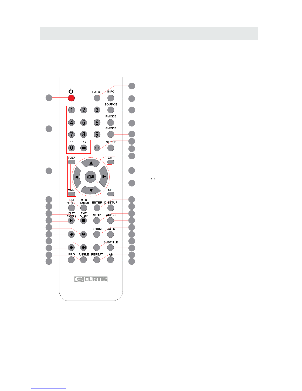
REMOTE CONTROL
1.STANDBY
To switch on the Tv or make the TV into
standby mode.
2.EJECT
To open or close the DVD player loader.
3.INFO
Show the information of the program you are watching.
4.SOURCE
Press this button to select an input source.
5.PMODE
Press this button to select a picture mode for different
picture qualities.
6.SMODE
Press this button to select sound setting for different
sound effects.
7.0-9
Allows you to change the channel of the TV.
8.
Switches back and forth between the current and
previous channels.
9.SLEEP
To select the amount of time before your TV turns
Off automatically.
10.VOL+/VOLIncreases/Decreases the Volume control.
11.CH+/CHSkips to the next/previous channel on TV mode.
12.UP/DOWN/LEFT/RIGHT
Moves the cursor upward/downward/to the left/to the right
when making a selection.
13.MENU
Displays the OSD Menu of the TV.
14.CC
Press the button to enter into the CC mode.
TITLE
To goto the title menu if the DVD disc has a title page.
15.MTS
To change among STEREO, MONO and SAP. If there is no
second language available for the signal received, LCD
Display audio will output to mono.
D.MENU
To show the menu of the DVD disc.
4
5
1
2
3
6
8
9
12
7
11
13
10
15
14
19
18
23
22
27
26
31
30
16
17
20
21
24
25
28
29
32
33
FAVFAV
EPGEPG
Universal Remote Code: 1218
Page 8
CONTROL REFERENCE GUIDE
5
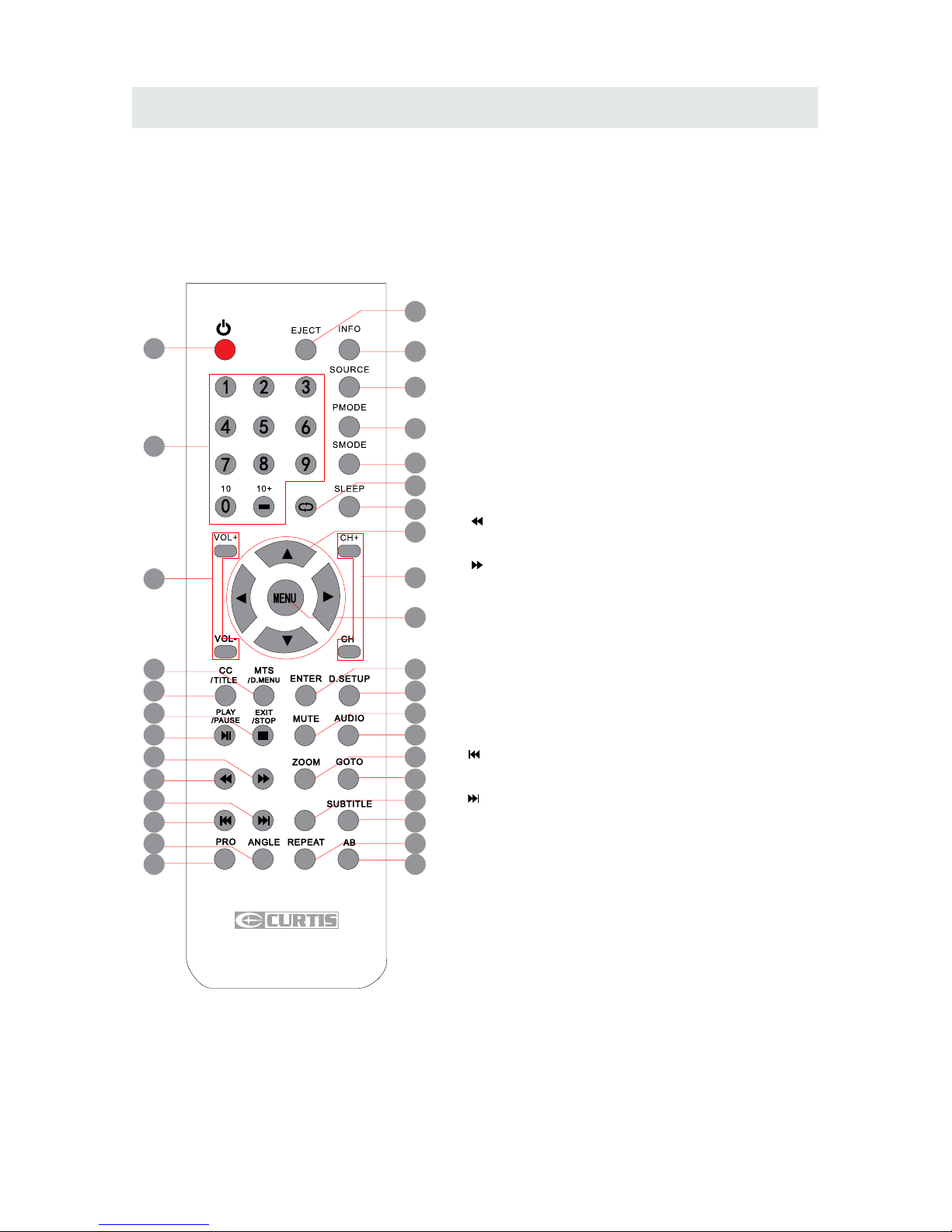
REMOTE CONTROL
16.ENTER
Enters the function selected.
17.D.SETUP
Press this button to show the DVD SETUP menu.
18.Play/Pause
Press this button to play or pause the DVD you’re watching.
19.Exit
Press this button to exit the on screen display.
Stop
Press this button to stop playing the DVD you’re watching.
20.MUTE
Press this button to mute or restore sound.
21.AUDIO
Press this button to change the audio language of the DVD.
22.
Fast reverse in DVD mode.
23.
Fast forward in DVD mode.
FAV
Press this button to show the favourite channel list on your TV.
24.ZOOM
To select a screen display size on your TV in DVD mode.
25.GOTO
Press this button to start playing the disc program from
the time you want.
26.
Previous chapter in DVD mode.
27.
Next chapter in DVD mode.
28.EPG
Press this button to select the electronic programme guide..
29.SUBTITLE
To show the subtitle for the program you're watching.
30.PRO
To edit the program list of your DVD disc in DVD mode.
31.ANGLE
To select different angles to which the picture suits your
preference.
32.REPEAT
Press this button for repeat the program.
33.AB
Press this button for repeat play point A and B.
4
5
1
2
3
6
8
9
12
7
11
13
10
15
14
19
18
23
22
27
26
31
30
16
17
20
21
24
25
28
29
32
33
FAVFAV
EPGEPG
Universal Remote Code: 1218
Page 9
CONTROL REFERENCE GUIDE
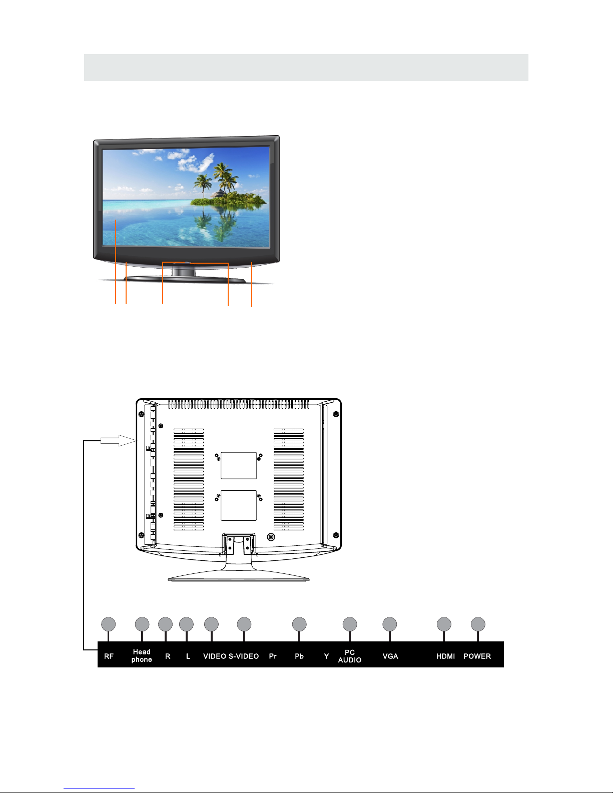
BACK VIEW
31 424
FRONT VIEW
6
1
4
10
9
11
2
3
8
7
6
5
1.Color LED Screen
2.Remote Sensor
Do not block this sensor or the
remote control will not work.
3.Standby Indicator
Indicates whether the unit is ON
or in STANDBY (OFF) mode.
Light in red: The unit is in STANDBY.
Light: in green:The unit is turned ON.
4. Speakers
1.TV ANTENNA Terminal
2.HEAD PHONE Jack
3.AUDIO IN Jack (Right)
4.AUDIO IN Jack (Left)
5.VIDEO IN Jack
6.S-VIDEO Jack
7.Y / PB / PR Jacks
8.PC AUDIOIN Jack
9.VGA IN Jack
10.HDMI IN Jack
11.DC IN (12V)
Page 10
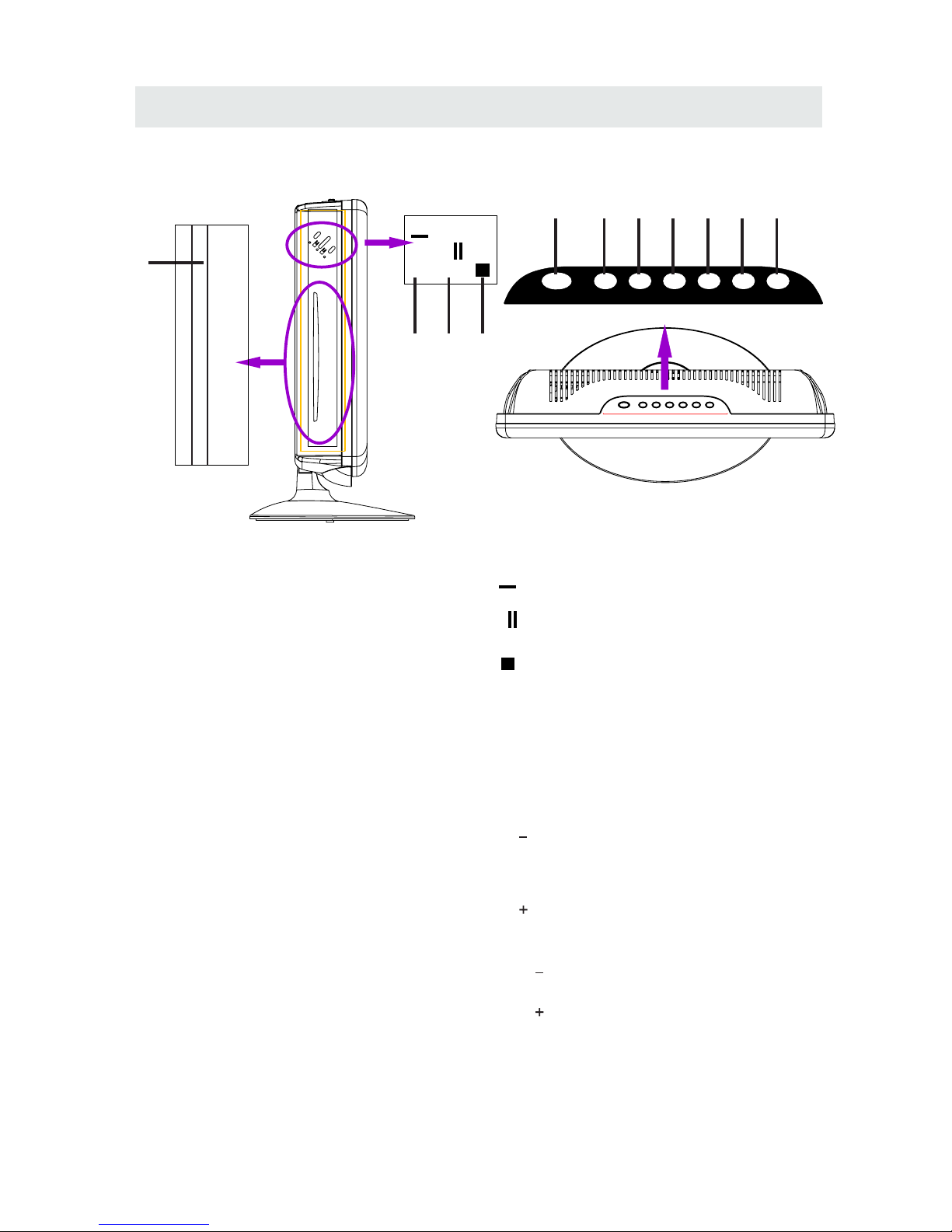
SIDE VIEW
CONTROL REFERENCE GUIDE
2. Bu tton
3. Bu tton
4. Button
7. Menu Button
9. CH Bu tton
11. VOL Bu tton
10. VOL Bu tton
5. STANDBY Button
7
1.Disc Door
Insert discs to disc door
Note: When inserting a disc, please
take note of the indication of direction
around the disc door for operation.
(Right direction: put the Mirror side of
the disc against yourself)
Press to start or resume playback of a disc.
Press to Eject a disc.
Press to stop the program of the disc.
Press to display the on-screen TV menu.
Press to change the TV channels and up
highlight selections on the menu screen.
8. CH Bu tton
Press to change the TV channels and down
highlight selections on the menu screen.
Press to adjust the volume up.
Press to adjust the volume down.
Press toturn the unit on and off.
1
Lab el Toward s Back
Label Towards Back
►
▲
STAN DBYSTAN DBY
INP UTINP UT MEN UME NU
CH-CH- CH+CH+
VOL -VOL - V OL+VOL +
OVER VIEW
2 3
4
5
6
7
8 9 10 11
▲
►
6. INPUT Button
Press to select the input source of the TV.
Page 11

CONNECTIONS
CONNECTING A TV ANTENNA / CABLE / S A TELLITE
To vi ew televis io n channels co rrectly, a sig nal must
be rece iv ed from one of the fo llowing so urces:
- An indoo r or outdoor aeria l antenna
- A ca bl e system
- A sate ll ite system
Fo r rec ei ving over-the -air TV broad casts , we
recomm end that yo u use an exte rn al fixe d an te nna.
Sh ou ld you require th e use of a tempor ar y a ntenna,
pl ea se ensure that you purc hase an anten na wi th
su ff icien t abi lity to receive in weak si gnal areas .
On ly w hen you a re in cl ose proximi ty t o a tr ansmi tt er
wi ll a tem po rar y ante nn a rep ro duce a sign al as
st ro ng ly as a fixed anten na.
To co nnect to other equ ipment suc h as a VCR, ca mcorder, satellit e sys te m or cable, etc.
CONNEC TING AN A/ V DEVICE
NOTE
Connecting to a VCR / Camcorder /
Satellite System / Cable
AUDIO OUT S-VIDEO OUT
AUDIO IN S-VIDEO IN
NOTE
CONNEC TING DEVICES WITH A COMPOSI TE (YELLOW RCA-TYPE)
VIDEO OUTPUT
Connecting to a VCR / Video Game System / Camcorder
AUDIO VIDEO OUT
AUDIO VIDEO IN
NOTE
Co nn ect the AUDIO and S-V IDEO cable
(n ot in cluded) as sh own.
Ma ke sure yo u co nnect t he c able from t he o ther
eq ui pment ( an d ) to
th is un it ( an d ).
Pl ea se refer to the u se r manua l for the oth er
eq ui pment for more inf ormatio n.
To con ne ct A/V de vices suc h as a V CR , video g am e system or c am corder.
Co nn ect the AUDIO / VIDEO ca ble (not incl uded) as show n.
Ma ke sure yo u co nnect t he c able from t he o ther eq ui pment ( and ) to this u ni t
( and ).
Pl ea se refer to the u se r manua l
fo r th e other e qu ipment fo r
mo re info rmation .
Sa te ll ite, cable or TV anten na
ca bl e to TV A NT ENNA
term in al (cable not in cluded)
To AUDIO / VID EO
IN ja cks (AV I N)
To AUDIO / VID EO
OUT ja cks
To S-V IDE O OUT / A UDIO OU T jacks
To AUD IO IN
jac ks (AV IN )
8
To DIO IN
jac ks (AV IN)
S VI-
Page 12
CONNECTIONS
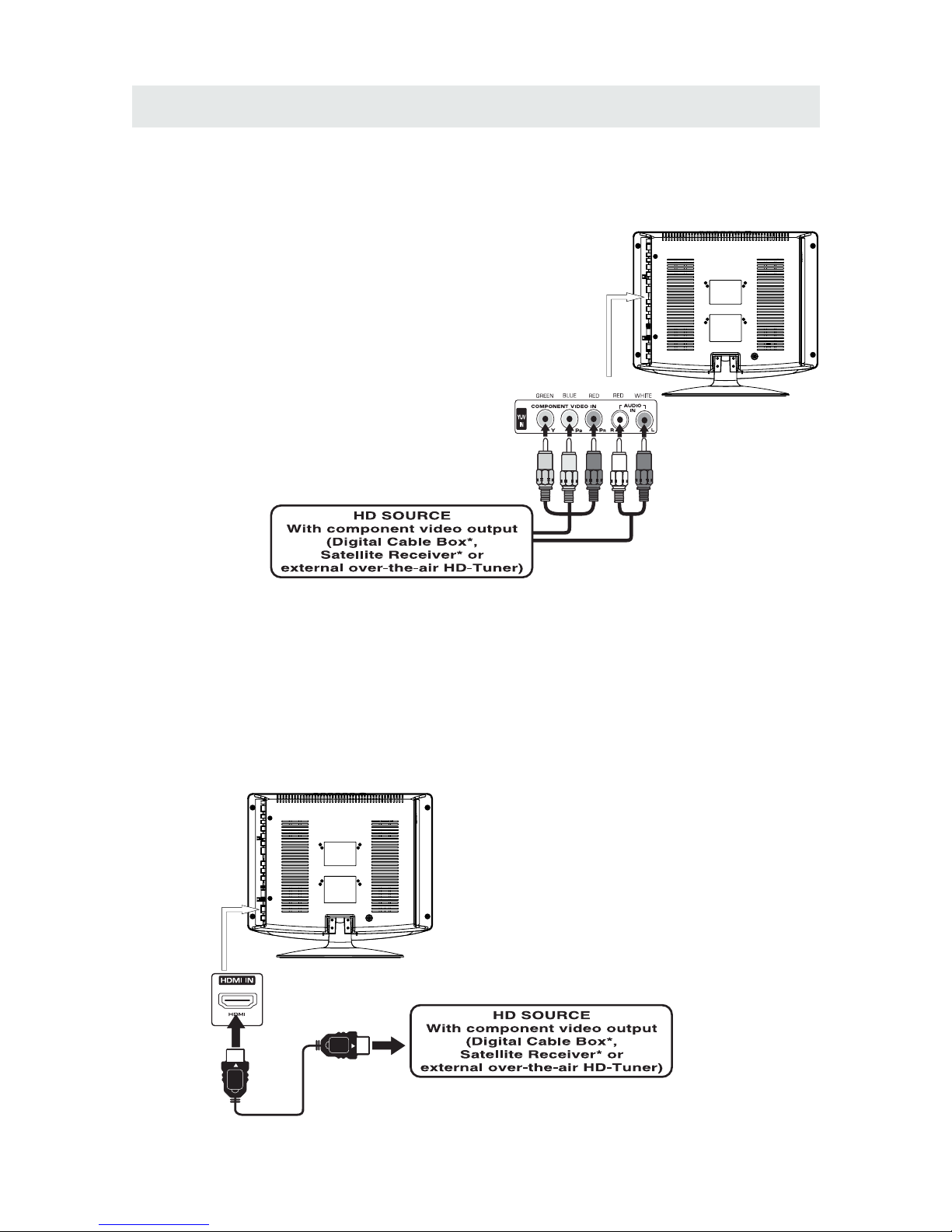
CONNEC TING A HIGH-DEFINITION (HD) SOURCE USING CONNECTION
OUT AUDIO OUT IN AUDIO I
NOT E
COMPONENT
COMPONE COMPONENT N
High -D efiniti on (H D) Devices with component video output must be connec te d to the Y inpu t.
Conn ec t the component video cable and audi o cable (not include d) as shown.
Ma ke sure yo u co nnect t he c ompon ent video c able an d au dio cab le f ro m the oth er equipm ent
( and ) to thi s unit and ).
When conn ecting a DVD pla yer to the televisio n,
the pictu re reso lu tion is solel y dependent upon
the resol ut ion suppor ted by the DVD player at tached.
DVD playe r res olution s var y from 480i to 1080 ,
and this tel ev ision can suppo rt DVD play ers up to
a maximum re so lution of 1080i .
PbPr
i
* May re quire a subscription
fo r rec eiving HD cha nnels ,
ch ec k with your cable/ satellite
se rvi ce provide r for detai ls.
To CO MP ONENT
VI DE O OUT jac ks
CONN EC TING A HIGH -DEFINITION (HD) SOU RCE USING HDMI CON NECTI ON
HDMI (High Definiti on Multime dia Interface ) sup por ts both video and aud io on a sing le digital connection
fo r us e with DV D pl ayers , DTV, set- top b oxes a nd othe r di gital AV d ev ices. H DM I was dev el oped to p rovi de
the tec hn ologies of High Bandwidth Digi tal Conten t Pro te ction (HDCP) as we ll as Digi tal Visual In te rfa ce
(D VI ) in one sp ec ifica ti on. HDC P is used to prot ec t digit al c ontent tr ansmitted a nd received b y
DVI- complia nt or HDMIcompl iant displ ays.
HDMI has the ca pabilit y to suppo rt standard, enhan ced or high-d efinition video plus st andard to
mult i-chann el surround-sound audio. HD MI feature s inc lude uncom pressed digita l video, a bandw id th of
up to 2.2 gigabytes per second (w ith HDT V signals), one connector (i nstead of several cables and
conn ectors), and co mmunica tion betwe en the AV source and AV devices such as DTVs.
To HDMI
IN jack
To HDMI
ja ckOUT
To COMPONENT
VIDEO IN jacks
( IN )COMPON ENT
To AUDI O
IN jack s
( IN )COMPON ENT
To AUDI O
OU T ja cks
Co nn ect the H DM I cable (no t inclu ded) as
sh ow n:
Ma ke sure yo u co nnect t he c able from t he
so ur ce eq uipment ( ) to this unit
( ).
HD MI OU T
HD MI IN
HDMI CABLE
(NOT INCLUDED)
9
Page 13
CONNECTIONS
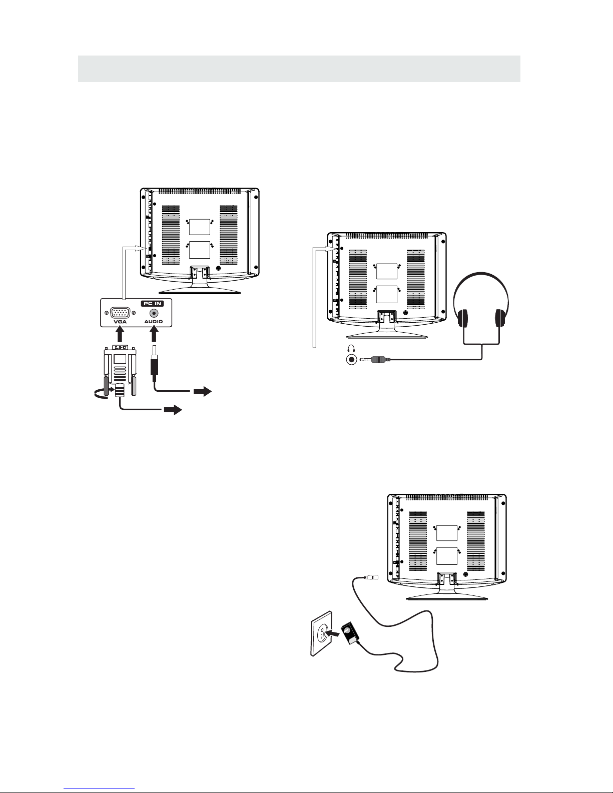
CONN ECTING A
AUDI O - PC O UT
VGA AUDIO - PC IN
PC
VGA
Co nn ect the 15-pi n D-SUB PC/VGA connector
from your co mputer to the 15-p in D-SUB PC/VGA
in pu t on this unit usin g a monitor cabl e and an
au di o cable (not inc luded) as sho wn.
Ma ke sure yo u co nnect t he c able from t he comput er
( an d ) to this unit
( and ) .
CONN EC TING THE POWER CORD
You can power your TV unit by plugg ing the Switc hing adap ter cord into the AC socket on the side of
th e un it and in to a w all AC power ou tlet. Che ck that t he r ated voltag e of y ou r unit ma tc hes your lo ca l
volt ag e. Make sure that the Switching adapt er cord is fully inserte d into the unit.
TO PC Conne ctor
TO AUDIO OUT jacks
NOT E
• Insert the power plug fully into the socket outlet
If the power plug is loose it could generate heat and
cause fire
connected to prevent electrical shock
• An apparatus with CL ASS I construction shall be
connected to a power socket outlet with a protective
grounding connection.
Do not tou ch the power plug with a wet h and
This may cause electrical shock
Do not use any power cord other than that prov ided
withthis TV This may cause fire or electr ical shock
Do not d amage the power cord
A dama ged cord may cause fire or electrical shock
• Do not move the TV with the cord plugge d in the
socket outlet.
• Do not place a heavy object on the cord or place
the cord near a high-temperature object.
• Do not twist the cord, bend it excessively, o r stretch it.
• Do not pull on the cord . Hold onto the power plug body when disconn ecting cord .
• Do not use a damaged power plug or s ocket outlet.
.
( ,
.)
.
( .)
. ( .)
.
( ).
•
•
•
To AC wall outlet
• Turn d own the volum e before
conn ecting hea dphones to
the unit, then adjust the
volume to your desired level.
• When headphone s are
conn ected, no sound will come
from the front speaker s.
Avoiding listening to sound a t high
levels fo r prolonge d period of time.
This m ay be harmful to you a nd may
caus e hearing loss.
NOT E
CONNEC TING HEADPHONES
Headphones
(1 /8 "[ 3.5mm ]dia meter plug )
NOT INCLU DED
10
Switching adapter
Page 14

WALL MOUNT INSTALLATION
INSTALL ING REMO VING THE BASE STAND
WAR NING/: The LED D is play is v ery fra gi le an d mu st be pro te cted at a ll t imes wh en r emovi ng the base
Stand
Be sure that no ha rd or sharp object or anything that could scratch or dama ge the LED display come s into
cont act with it Do NOT exer t pressure on t he front of the uni t at any time because the screen coul d crack
1 Disc onnect all cables or cords connected to the unit
2 Lay the unit down on a flat surface wit h the back side f acing up Please make sure to pla ce a soft
cushioned material such as a pillow or thick piece of foam b eneath the sc re en
3 To remove th e base stand loosen screws off the holes then pull downw ards to release
the base stand
4 To insta ll the base stand put the st and into the hole at the bot tom of the TV t hen inser t screw s to the
holes and tighten.
,
.
, ,
. .
. .
. .
. ,
.
. ,
MO UN TING ON THE WAL L
NOT E
Remove the base stand be fore mount ing the unit on the wa ll.
This unit is VESA-compliant, and is designed to be wall-mounted with a VESA-compliant 3” x 3”
(75mm x 75mm) mounting kit designed for flat-panel TVs (not supplied). Mount this unit according to
the instructions included in the mounting kit.
11
3"
3"
Length of screw should not exceed 10mm.
Page 15

INITIAL SETUP
Wh en you turn on your t ele vision set for
th e fir st ti me, b e sure to p lac e it on a solid
st able surface .
To avo id da nger, do n ot expose the T V
to water, or a hea t sou rce
(e .g. lamp, candle, radiator ).
Do not obstruct the ventilation grid
at t he rear a nd be s ure to le ave s uff ici ent
ga ps around the unit.
PUTTING THE UNIT ON A PROPER PL ACE
12
SOUR CE SELECT ION
1. Press the button on the remo te control.
2.
TV, AV , S-Video, , HDMI , V GA)
and sel ect any of t hem using the button or
the bu tton.
ource
Note:
Be fore watching pleas e make sure all necessary
cables and devices are connected.
SOUR CE
ENT ER
DVD, Comp onent
Us e or button t o sel ect the options
(
the
(T he sc re en wi ll ch ang e to your desired s ).
INPUT SOURCE
TV
AV
S-Video
Component
HDMI
VGA
DVD
TURNING THE UNIT ON FOR THE FIRST TIME
Af ter yo u have initiall y connected your TV
anten na or cable(no s et to p box )
tu rn the te levision ON.
A scree n will display asking yo u to ru n a
to se arc h and receiv e
avai lable local digi tal ch ann els.
It is he re where you will sel ect an tenna options
an d run .
Chann els will be s tor ed in t he TV tuner.
Press th e bu tton on the remote control.
.
Pr ess t he butto n to highlight A IR/ CABLE.
Channel Auto Scan
Channel Auto Scan
MENU
TV
Please run
Channel Auto Scan
in the TV menu
Using the buttons, scroll to highlight mode
Page 16

INITIAL SETUP
13
AIR.
Set up
12
6
Tim
e
Pict ure Audio
Ca ble Sy st em
Au to
MENU
St art to Sc an
Mo ve Ne xt Ex it
Set up
Mo ve Ne xt Exi t
MENU
Pic ture Audio
12
e
miT
RF C H
Fo und
7
4
Air Mode: Select wh en con nected to an
in doo r/outdoo r ante nna.
AIR
Setu p
LOC K
12
6
Tim
e
Pict ure Audio
CHAN NEL
Air /C able
Au to Sc an
Fa vor it eFa vor it e
Sho w Hi deSho w Hi de
Ch ann el NoCh ann el No
Ch ann el labelCh ann el label
DT V Sig nalD TV Si gna l
Air
Se lec t Ex itMo ve
MENU
KO CEKO CE L BL B
Se lec t Ex itMo ve
MENU
Setu p
12
6
Tim
e
Pict ure Audio
Air /C able
Au to Sc an
Fa vor it eFa vor it e
Sho w Hi deSho w Hi de
Ch ann el NoCh ann el No
Ch ann el labelCha nnel la bel
DT V Sig nalD TV Si gna l
Ca ble
Se lec t Ex itMov e
MENU
Se lec t Ex itMov e
MENU
Cable Mode: S elect if you subs cribe to
a pay televisi on ser vice inclu d i ng sat ellite.
CABLE
How to Navigate
Set up
12
6
Tim
e
Pict ure Audio
Ca ble Sy st em
Au to
MENU
St art to Sc an
Mo ve Ne xt Ex it
Set up
Mo ve Ne xt Exi t
MENU
Pic ture Audio
12
6
e
miT
RF C H
Fo und
7
4
CHAN NEL
CHAN NELCHAN NEL
CHAN NEL
CHAN NEL
Press the button to highlight
Using the ◄► button to highlight CABLE.
Press the ▼ button to select AUTOSCAN then
press the ► button to start Channel Auto Scan.
Press the ▼ button to select AUTOSCAN.
Press the ENTER button and the cursor will move
up and CABLE SYSTEM will be displayed next.
Press ► the button to select STD > IRC > HRC >
Auto (Auto is recommended).
Press the ▼ button to select Auto Scan
and press ENTER to start Channel Auto Scan.
Channel Auto Scan may take several minutes
to complete.
Channel Auto Scan may take several minutes
to complete.
NOTE: For cable or satellite users with no TV antenna, there no need to run Channel Auto Scan.
Connect your cable or satellite set top box to one of the available inputs on the TV for viewing.
Page 17

TV SETUP
14
Set up
12
6
Tim
e
Pic ture Audio
Picture Mo de
Co nt ra st
Brightnes s
Co lo r
Tin t
Sh arpness
Co lo r Mod e
St andard
No rmal
Mo ve Ad just Exit
MEN U
50
50
50
0
50
Pictu re
PICTURE MENU
Set up
12
6
Tim
e
Pic ture Audio
Picture Mo de
Co nt ra st
Brightnes s
Co lo r
Tin t
Sh arpness
Co lo r Mod e
St andard
No rmal
Mo ve Se le ct E xi t
MEN U
50
50
50
0
50
Set up
Par ental
12
6
Tim
e
Pic ture Audio
TV
Picture Mo de
Co nt ra st
Brightnes s
Co lo r
Tin t
Sh arpness
Co lo r Mod e
St andard
No rmal
Mo ve Ad just Exit
MEN U
50
50
50
0
50
The PICTURE menu offers options to enhance and refine the picture displayed on your TV
based on ambient room light and personal preferences.
Adjustment options include contrast, brightness, color, sharpness and color temperature.
How to Navigate:
Press the MENU button on the remote control. Navigate using the ◄► buttons to select PICTURE.
Press the ▼ button to highlight ,
then press the ► button to select your viewing
preference from 4 factory options:
STANDARD > DYNAMIC > MOIVE > PERSONAL.
The STANDARD setting is recommended for most
viewing environments.
Depending on the ambient light level in the room,
you may find one of the other options
more pleasing.
To make more critical picture adjustments based on your own preferences in PERSONAL:
Use the ▼ button to highlight Contrast.
Navigate using the ◄► buttons to
increase or decrease contrast intensity.
Use the ▼ button to highlight Brightness.
Navigate using the◄► buttons to
increase or decrease overall brightness.
Page 18

TV SETUP
15
Pictu re
PICTURE MENU
Set up
12
6
Tim
e
Pic ture Audio
Picture Mo de
Co nt ra st
Brightnes s
Co lo r
Tin t
Sh ar pness
Co lo r Mod e
St andard
No rmal
Mo ve Ad ju st Ex it
MEN U
50
50
50
0
50
Set up
12
6
Tim
e
Pic ture Audio
Picture Mo de
Co nt ra st
Brightnes s
Co lo r
Tin t
Sh ar pness
Co lo r Mod e
St andard
No rmal
Mo ve Ad ju st Ex it
MEN U
50
50
50
0
50
Set up
12
6
Tim
e
Pic ture Audio
Picture Mo de
Co nt ra st
Brightnes s
Co lo r
Tin t
Sh ar pness
Co lo r Mod e
St andard
No rmal
Mo ve Ad ju st Ex it
MEN U
50
50
50
0
50
Set up
12
6
Tim
e
Pic ture Audio
Picture Mo de
Co nt ra st
Brightnes s
Co lo r
Tin t
Sh ar pness
Co lo r Mod e
St andard
No rmal
Mo ve Ad ju st Ex it
MEN U
50
50
50
0
50
The PICTURE menu offers options to enhance and refine the picture displayed on your TV
based on ambient room light and personal preferences.
Adjustment options include contrast, brightness, color, sharpness and color temperature.
Press the MENU button on the remote control. Navigate using the ◄► buttons to select PICTURE.
Use the ▼ button to highlight Color.
Navigate using the ◄► buttons to
increase or decrease color intensity.
Use the ▼ button to highlight Tint.
Navigate using the ◄► buttons to adjust colors
toward green or reddish tint.
Use the ▼ button to highlight Sharpness.
Navigate using the ◄► buttons to soften or
view crisper edges in the picture.
Use the ▼ button to highlight Color Temperature.
Navigate using the ◄► buttons to select COOL
(more bluish tone), NORMAL or WARM.
The default setting is NORMAL.
WARM mode will provide color that is calibrated
to D6500° Kelvin, the standard color that
broadcast stations and the Motion Picture
industry consider as the most accurate to
view programming.
Note:
When adjustments are completed, you may select another menu by pressing
the Menu button.
Page 19

TV SETUP
16
AUDIO MENU
Audio
Surround
Set up
12
6
Tim
e
Sound Mo de
Ba ss
Treble
Ba la nce
Surround
Au dio Language
St andard
En glish
Mo ve Se lect Ex it
MEN U
50
50
50
Of f
Pict ure Audio
Set up
12
6
Tim
e
Sound Mo de
Ba ss
Treble
Ba la nce
Surround
Au dio Language
St andard
En glish
Mo ve Adj us t Exit
MEN U
50
50
50
Of f
Pict ure Audio
Set up
12
6
Tim
e
Sound Mo de
Ba ss
Treble
Ba la nce
Surround
Au dio Language
St andard
En glish
Mo ve Adj us t Exit
MEN U
50
50
50
Of f
Pict ure Audio
How to Navigate:
Press the MENU button on the remote control. Navigate using the ◄► buttons to select AUDIO.
The AUDIO menu offers options to make sound enhancements while listening through the built-in
speakers and personal preferences.
Adjustment options include bass, treble, balance, surround and audio language.
Press the ▼ button to highlight SoundMode,
then press the ► button to select your sound
preference from 4 factory options:
STANDARD > MUSIC > MOVIE > PERSONAL.
The STANDARD setting is recommended for most
sound environments.
Depending on the surroundings in the room,
you may find one of the other options
more pleasing.
To make more critical audio adjustments based on your own preferences in PERSONAL:
Use the ▼ button to highlight Bass.
Navigate using the ◄► buttons to
increase or decrease low frequency intensity.
Use the ▼ button to highlight Treble.
Navigate using the ◄► buttons to
increase or decrease high frequency intensity.
Page 20

TV SETUP
17
Set up
12
6
Tim
e
Sound Mo de
Ba ss
Treble
Ba la nce
Surround
Au dio Language
St andard
En glish
Mo ve Selec t Ex it
MEN U
50
50
50
Of f
Pict ure Audio
Surround
Set up
12
6
Tim
e
Sound Mo de
Ba ss
Treble
Ba la nce
Surround
Au dio Language
St andard
En glish
Mo ve Adj us t Exit
MEN U
50
50
50
Of f
Pict ure Audio
Set up
12
6
Tim
e
Sound Mo de
Ba ss
Treble
Ba la nce
Surround
Au dio Language
St andard
En glish
Mo ve Selec t Ex it
MEN U
50
50
50
Of f
Pict ure Audio
AUDIO MENU
Audio
How to Navigate:
Press the MENU button on the remote control. Navigate using the ◄► buttons to select AUDIO.
The AUDIO menu offers options to make sound enhancements while listening through the built-in
speakers and personal preferences.
Adjustment options include bass, treble, balance, surround and audio language.
Note:
When adjustments are completed, you may select another menu by pressing
the Menu button.
Use the ▼ button to highlight Balance.
Navigate using the ◄► buttons to adjust sound
towards the right or left speaker.
Use the ▼ button to highlight Surround.
Navigate using the ► button to turn the
dimensional surround effect ON or OFF.
(for built-in speakers only).
Use the ▼ button to highlight Audio Language.
Navigate using the ◄► buttons to select to listen
to an alternative language broadcast
(if available) English > Spanish > French.
You may select an alternative language using
the remote control by pressing MTS)
Page 21

TV SETUP
18
TIME MENU
12
6
Tim
e
Set up
Sl eep Tim er
Tim e Zone
Da ylight S aving Time
Cl ock
Mo ve Selec t Ex it
MEN U
Pic ture
Of f
Pa cific
Of f
200 7 1 0 3 1 04 04 PM
12
6
Tim
e
Audio
Set up
Sl eep Tim er
Tim e Zone
Da ylight S aving Time
Cl ock
Mo ve Selec t Ex it
MEN U
Pic ture
Of f
Pa cific
Of f
200 7 1 0 3 1 04 04 PM
12
6
Tim
e
Audio
Set up
Sl eep Tim er
Tim e Zone
Da ylight S aving Time
Cl ock
Mo ve Selec t Ex it
MEN U
Pic ture
Of f
Pa cific
Of f
200 7 1 0 3 1 04 04 PM
12
6
Tim
e
Audio
Set up
Sl eep Tim er
Tim e Zone
Da ylight S aving Time
Cl ock
Mo ve Selec t Ex it
MEN U
Pic ture
Of f
Pa cific
Of f
200 7 1 0 3 1 04 04 PM
12
6
Tim
e
Audio
Press the MENU button on the remote control. Navigate using the ◄► buttons to select TIME.
How to Navigate:
The TIME menu includes adjustment of settings for your local time zone and daylight savings time.
The clock will adjust automatically after the initial Channel Auto Scan of available broadcast
channels in your area.
Note:
When adjustments are completed, you may select another menu by pressing
the Menu button.
Use the ▼ button to highlight SleepTimer,
then press the ► button to select among:
5min, 10min, 15min, 30min, 45min, 60min,
90min, 120min, 180min, 240min and off.
Use the ▼ button to highlight TimeZone,
then press the ► button to select among:
EASTERN > CENTRAL > MOUNTAIN >
PACIFIC > ALASKA > HAWAII.
Use the ▼ button to highlight
Daylight Saving Time.
Navigate using the ◄► buttons to turn
this feature on or off.
Clock: Display the time at present.
Page 22

TV SETUP
19
SETUP MENU
Setu p
Lock
12
6
Time Chan nel
Men u La ngua ge
Tran spar enc y
Zoo m Mo de
Noi se Red ucti on
Adv ance
Clo se C apti on
XVS
Res tore D efau lt
Eng lish
Mov e Sele ct Ex it
MENU
Pict ure
Off
Nor mal
Off
Setu p
Audio
On
12
6
Time
Men u La ngua ge
Tran spar enc y
Zoo m Mo de
Noi se Red ucti on
Adv ance
Clo se C apti on
XVS
Res tore D efau lt
Eng lish
Mov e Sele ct Ex it
MENU
Pict ure
Off
Nor mal
Off
Setu p
Audio
On
1212
6
Time
Men u La ngua ge
Tran spar enc y
Zoo m Mo de
Noi se Red ucti on
Adv ance
Clo se C apti on
XVS
Res tore D efau lt
Eng lish
Mov e Sele ct Ex it
MENU
Pict ure
Off
Nor mal
Off
Setu p
Audio
On
6
Time
Men u La ngua ge
Tran spar enc y
Zoo m Mo de
Noi se Red ucti on
Adv ance
Clo se C apti on
XVS
Res tore D efau lt
Eng lish
Mov e Sele ct Ex it
MENU
Pict ure
Off
Nor mal
Off
Setu p
Audio
On
1212
6
Time
Men u La ngua ge
Tran spar enc y
Zoo m Mo de
Noi se Red ucti on
Adv ance
Clo se C apti on
XVS
Res tore D efau lt
Eng lish
Mov e Sele ct Ex it
MENU
Pict ure
Off
Nor mal
Off
Setu p
Audio
On
6
Time
Men u La ngua ge
Tran spar enc y
Zoo m Mo de
Noi se Red ucti on
Adv ance
Clo se C apti on
XVS
Res tore D efau lt
Eng lish
Mov e Next Ex it
MENU
Pict ure
Off
Nor mal
Off
Setu p
Audio
On
Are yo u sure ?
No
Yes
Press the MENU button on the remote control. Navigate using the ◄► buttons to select SETUP.
How to Navigate:
In the SETUP menu you may change the initial set up of preferences that include settings for
language, menu display, computer monitoring, closed captions, enhancement of black detail
in the picture and resetting your TV back to its factory default status.
Use the▼ button to highlight Menu Language,
Press the ► button to select the language
you prefer among English, French and Spanish.
Use the ▼ button to highlight Noise Reduction.
Navigate using the ◄► buttons to reduce video
noise: Off > Low > Medium > High
Default setting: medium)
Use the ▼ button to highlight Transparency.
Navigate using the ◄► buttons to turn Off or On
the translucent effect of the OSD.
Use the ▼ button to highlight XVS.
Navigate using the ◄► buttons to select:
Off > On. XVS provides noticeable black detail
enhancement that may be preferred.
When
prompted,
Select "Yes"
to confirm.
Use the ▼ button to highlight Zoom Mode.
Navigate using the ◄► buttons to select the
viewing mode: Normal > Wide > Zoom > Cinema.
Use the ▼ button to highlight Restore Default.
Press the ► button to automatically set all
adjustments back to their original settings.
Page 23

SETUP MENU
Setu p
12
6
Time
CC M ode
Bas ic S ele cti on
Adv ance d Se lec tion
Opt ion
On
Mov e
MENU
Pict ure
CC1
Ser vice 1
Setu p
Audio
Sel ect Ex it
12
6
Time
CC M ode
Bas ic S ele cti on
Adv ance d Se lec tion
Opt ion
On
Mov e
MENU
Pict ure
CC1
Ser vice 1
Setu p
Audio
Sel ect Ex it
12
6
Time
CC Mod e
Basi c Sel ecti on
Adv anced Se lecti on
Opt ion
On
Mov e
MENU
Pict ure
CC 1
Ser vice 1
Setup
Audio
Se lec t Ex it
12
6
Time
CC M ode
Bas ic S ele cti on
Adv ance d Se lec tion
Opt ion
On
Mov e
MENU
Pict ure
CC1
Ser vice 1
Setu p
Audio
Nex t Ex it
12
6
Time
Mod e
Fon t S tyle
Fon t S ize
Fo nt E dge Styl e
Fon t E dge Colo r
FG Col or
BG Col or
FG O pacit y
BG O pac ity
Exi t
MENU
Pict ure
Set up
Audio
Cus tom
Def ault
Def ault
Def ault
Def ault
Def ault
Def ault
Def ault
Def ault
Mo ve
Se lec t
TV SETUP
Lock
12
6
Time Chan nel
Men u L ang ua ge
Tran spare ncy
Zoo m Mod e
Noi se Re duc tion
Adv ance
Clo se Ca pti on
XVS
Res tore Def ault
Eng lish
Mo ve Se le ct Ex it
MENU
Pict ure
Off
Nor mal
Off
Setup
Audio
On
12
6
Time
Men u L ang ua ge
Tran spare ncy
Zoo m Mod e
Noi se Re duc tion
Adv ance
Clo se Ca pti on
XVS
Res tore Def ault
Eng lish
Mo ve Ne xt Ex it
MENU
Pict ure
Off
Nor mal
Off
Setup
Audio
On
20
The SETUP menu includes adjustments for activating the Closed Caption feature for display
on the television and customizing CC display types and font styles.
How to Navigate:
Press the MENU button on the remote control.
Navigate using the ◄► buttons to select SETUP.
Press the▼ button to highlight Closed Caption
then press the ► button to select from the
following options.
Use the ▼ button to highlight Advance Selection.
Navigate using the ◄► buttons to select
Service 1 - 6.
Use the ▼ button to highlight CC Mode.
Navigate using the ◄► buttons to select
Off > On > CC on Mute.
Use the ▼ button to highlight Option.
Press the ► button to enter a menu with options
to cus tomize text fonts, colors and opacities.
Use the ▼ button to highlight Basic Selection.
Navigate using the ◄► buttons to select
CC 1-4, Text 1-4.
Note:
When adjustments are completed, you may select another menu by pressing
the Menu button.
Page 24

TV SETUP
SETUP MENU
Setu p
Set up
12
6
Tim
e
Picture Audio
Clo ck
Pha se
Aut o
Mov e Adj ust Exi t
MENU
50
50
50
0
H - pos
V - pos
Set up
12
6
Tim
e
Picture Audio
Clo ck
Pha se
Aut o
Mov e Adj ust Exi t
MENU
50
50
50
0
H - pos
V - pos
Set up
12
6
Tim
e
Picture Audio
Clo ck
Pha se
Aut o
Mov e Adj ust Exi t
MENU
50
50
50
0
H - pos
V - pos
Set up
12
6
Tim
e
Picture Audio
Clo ck
Pha se
Aut o
Mov e Next Exi t
MENU
50
50
50
0
H - pos
V - pos
Are yo u sure ?
No
Yes
Lock
12
6
Time Ch annel
Men u L ang uage
Tran spar enc y
Zoo m Mo de
Noi se Re duc tion
Adv ance
Clo se Cap tion
XVS
Res tore Def ault
Eng lish
Mov e Sele ct Ex it
MENU
Pict ure
Off
Nor mal
Off
Setu p
Audio
On
12
6
Time
Men u L ang uage
Tran spar enc y
Zoo m Mo de
Noi se Re duc tion
Adv ance
Clo se Cap tion
XVS
Res tore Def ault
Eng lish
Mov e Sele ct Ex it
MENU
Pict ure
Off
Nor mal
Off
Setu p
Audio
On
Set up
12
6
Tim
e
Picture Audio
Clo ck
Pha se
Aut o
Mov e Adj ust Exi t
MENU
50
50
50
0
H - pos
V - pos
21
In the SETUP menu you may adjust the position of images displayed on screen once you connect
an input signal from your PC. Recommended resolution is 1366 x 768.
If your PC system uses a standard signal mode, the screen will adjust automatically.
Connect an optional 3.5mm audio cable for stereo sound.
How to Navigate:
After connecting to a PC, press the SOURCE button and highlight VGA, then press the ENTER
button.
Press the MENU button on the remote control
and navigate using the ◄► buttons to select
SETUP. Press the ▼ button to highlight
Advanced, then press the ►button to select
from the following options.
Use the ▼ button to highlight Clock.
Navigate using the ◄► buttons to control the
width of the image.
Use the ▼ button to highlight H-POS.
Navigate using the ◄► but tons to adjust the
position of images displayed from side to side.
Use the ▼ button to highlight Phase.
Navigate using the ◄► buttons to improve focus
and image stability.
When
prompted,
Select "Yes"
to confirm.
Use the ▼ button to highlight V-POS.
Navigate using the ◄► buttons to adjust the
position of images displayed up and down.
Use the ▼ button to highlight AUTO.
Press the ► button to automatically adjust the
display to the best setting.
Page 25

TV SETUP
Lock
PARENTAL MENU
Set up
12
6
Tim
e
Pic ture Audio
Enter Pas sw or d
Ex it
MEN U
0 9~
Set up
12
6
Tim
e
Pic ture Audio
Ch an ge Pa ss wo rd
Sy st em Lo ck
US
Ca na da
Re se t RRT
RR T Setting
Se le ct
Ex it
MEN U
On
Mo ve
Set up
12
6
Tim
e
Pic ture Audio
Ch an ge Pa ss wo rd
Sy st em Lo ck
US
Ca na da
Re se t RRT
RR T Setting
Ne xt
Ex it
MEN U
On
Mo ve
22
Set up
12
6
Tim
e
Pic ture Audio
En te r New Password
Co nf irm Pas sw or d
Ex it
MEN U
0 9~
In the PARENTAL menu you may block television by inputting passwords.
To gain access and select your preferences within the Parental menu
make certain your input is set to TV.
Press the MENU button on the remote control. Navigate using the ◄► buttons to select Parental.
How to Navigate:
Press the ▼ button to highlight
Enter Password. Enter your 4 digit code
(factory default code is "0000")
unless previously changed.
Use the numeric buttons to input a new
4 digit code by two times.
To change the password, press the ► button
to display a screen to enter your new password,
then confirm again.
To make changes to PARENTAL controls,
Highlight SYSTEM LOCK then press
the ► button to ON.
NOTE:
RRT Setting and Reset RRT are not user's adjustable settings.
Page 26

TV SETUP
Lock
PARENTAL MENU
Set up
12
6
Tim
e
Pict ure Audio
TV
MPA A
Mov e Exi t
MENU
N A
Se lec t
Set up
12
6
Tim
e
Pict ure Audio
TV
MPA A
Mov e Exi t
MENU
N A
Ne xt
Set up
12
6
Tim
e
Pict ure Audio
MENU
Blo ck Pres s ENT ER t o lock or unl ock
TV RAT ING
TV Y
TV Y 7
TV G
TV P G
TV 1 4
TV M A
AL L FV V S L D
Ne xt Exi tMo ve
23
N/ A
In the PARENTAL menu you may block television and movie programming based on
U.S TV and movie rating guidelines. To gain ac cess and select your preferences
within the Parental menu make certain your input is set to TV.
How to Navigate:
Press the MENU button on the remote control. Navigate using the ◄► buttons to select Parental.
Press the ▼ button to highlight ENTER PASSWORD. Enter your 4 digit code
(factory default code is "0000") unless previously changed.
To set parental controls for television programming or DVD movies, press the ▲▼buttons to
highlight US. Navigate using the ◄► buttons to highlight TV/MPAA menu.
Highlight TV, then press the ► button to enter the TV Ratings menu to select your preference.
Highlight MPAA then press the ► button repeatedly to select your movie rating preference.
Page 27

TV SETUP
Lock
PARENTAL MENU
Set up
Ca nad a E ngli sh
Ca nad a F renc h
Mo ve
Se lec t Ex it
MENU
Pict ure Audio
12
6
Tim
e
G
G
Set up
Ca nad a E ngli sh
Ca nad a F renc h
Mo ve
Se lec t Ex it
MENU
Pict ure Audio
12
6
Tim
e
G
G
24
In the PARENTAL menu you may block television and movie programming based on
Canadian TV and movie rating guidelines. To gain ac cess and select your preferences
within the Parental menu make certain your input is set to TV.
How to Navigate:
Press the MENU button on the remote control. Navigate using t he ◄► buttons to select Parental.
Press the button to highlight ENTER PASSWORD. Enter your 4 digit code
(factory default code is "0000") unless previously changed.
To set parental controls for television programming or DVD movies, press the ▲▼ buttons to
highlight Canada.Navigate using the◄► buttons to highlight Canada English/Canada French menu.
Navigate using the ▼ button to highlight CANADA ENGLISH, then press the ► button repeatedly
to select your ratings preference.
Navigate using the ▼ button to highlight CANADA FRENCH, then press the ► button repeatedly
to select your ratings preference.
NOTE:
When adjustments are completed, you may select another menu by pressing
the Menu button.
Page 28

TV SETUP
TV MENU
Chan nel
Setu p
12
6
Tim
e
Pic ture Audio
Air /C able
Au to Sc an
Fa vor it e
Ad d Dele te
Ch ann el N o
Ch ann el Lab le
DT V S ign al
Air
Mo ve Nx et E xit
MENU
50 3
KO CE L B
Goo d
Set up
12
6
Tim
e
Pict ure Audio
Mo ve Pre ss 扙NT ER Cha nge Exi t
MENU
Channel Program Name Favorite
ATSC 1
ATSC 2
ATSC 3
KO CE HD
KO CE SD
KO CE LB
2 0
14 1
14 2
14 3
50 1
50 2
66 0
50 3
Prev Next
Setu p
12
6
Tim
e
Pic ture Audio
Air /C able
Au to Sc an
Fa vor it e
Ad d Dele te
Ch ann el N o
Ch ann el Lab le
DT V S ign al
Air
Mo ve Ne xt E xit
MENU
50 3
KO CE L B
Goo d
Set up
12
6
Tim
e
Pict ure Audio
Mo ve Pre ss 扙NT ER Cha nge Exi t
MENU
Channel Program Name Add/Delete
Prev Next
66 0
ATSC 1
ATSC 2
ATSC 3
KO CE HD
KO CE SD
KOCE LB
2 0
14 1
14 2
14 3
50 1
50 2
50 3
Setu p
12
6
Tim
e
Pic ture Audio
Air /C able
Au to Sc an
Fa vor it e
Ad d Dele te
Ch ann el N o
Ch ann el Lab le
DT V S ign al
Air
Mo ve Ne xt E xit
MENU
50 3
KO CE L B
Goo d
Set up
12
6
Tim
e
Pict ure Audio
Mo ve Ne xt Exit
MENU
K B B C - D T
25
The TV menu provides for the setup of your television to receive TV channels, store your favorites,
add or skip channels and label them by their call letters.
How to Navigate:
Press the MENU button on the remote control. Navigate using the ◄► buttons to select TV.
Press the ▼ button to highlight your preferences.
Highlight FAVOURITE to add channels to your Favorites List. Navigate using the ▲▼◄► buttons
to select channels to be added or deleted from your list. Press the ENTER button to add or delete
a channel. A checkmark indicates a channel has been added. You may also display your favourite
list from the remote control by pressing FAV.
Highlight to select ADD/DELETE or skip channels already in memory. Navigate using the ▲▼◄►
buttons to access the list of available channels. Press the ENTER button to change the channels
status. A checkmark indicates a channel has been added.
Highlight CHANNEL LABEL to name or rename a broadcast channel. Navigate using the ► button
to enter the screen menu to re-label a channel. Use the ▲▼ buttons to spell out each letter,
number or character. Use the ◄► buttons to advance to the next space.
Page 29

TV SETUP
ZOOM MODE
1 NORMAL.
2 WIDE.
3 ZOOM.
4 CINEMA.
26
FAVFAV
EPGEP G
The ZOOM function offers several viewing display options on the 16:9 screen.
Press ZOOM to cycle through the following widescreen settings.
Recommended for viewing native
widescreen content and
undistorted 4:3 images.
(With Black Bars)
Stretches certain 4:3 content and
may reduce the black bars.
Stretches the image both vertically
and horizontally to fill the screen
when viewing widescreen content.
The zoom effect will crop images
somewhat.
When viewing 4:3 content,
Cinema mode will fill the entire
screen eliminating the side black bars.
It may also eliminate or reduce black
bars on certain widescreen movies.
Page 30

DISC FORMATS
Th e uni t can play:
REGI ON MA NAGEMENT INFORMATIO N
Reg ion Management In formation: Thi s unit is
desi gn ed and manufactured to respon d to the
Reg ion Management In formation that is en coded
on DVDs. If the region numb er printed on the
DV D do es not co rres pond to the reg ion num be r
of this unit, this unit can not play that disc.
Th e re gi on numb er of th is eq ui pment i s .
ICON S USED ON DVDs
Sa mp le Icons
Lang ua ge selections for audi o
Lang ua ge selections for subt itles
Screen aspect ra tio
Mult ip le camera angles
Reg ion code indicato r
TI TL ES, CHAPTERS AND TRAC KS
• DVDs are divided into "TITLES" and "CHAPTERS".
If the disc has more than o ne movi e on i t,
each movie would be a separate "TITLE".
“CHA PTERS" are se ctions of titles.
• Audio CDs are divided into "TRAC KS".
NOT E
Nu mb ers iden tify eac h title, chap te r and track
on a d is c. Most d is cs have the se numb er s re cord
on t he m, but so me d o not.
NOT ES ON UNAUTHO RI ZED DISCS
You ma y not be ab le t o playbac k so me DVDs
on this eq uipment if th ey were purchas ed from
ou ts ide your geog raphic are a or mad e for
bu si ness purpo ses.
DVDs
[8 cm/12 cm disc]
Au dio CDs
[8 cm/12 cm disc]
CD R CD RW- -
Compatible
A "TRACK " is usuall y one song on a n Audio CD.
27
NOTES ON COPYRIGHT
It is forbidden by law to copy, broadcast, show,
broadcast on cable, play in public or rent
copyrighted material without permission.
Apparatus Claims of U.S. Patent Nos. 6,836,549;
6,381,747; 7,050,698; 6,516,132; and 5,583,936
licensed for limited viewing uses only.
DVDs are copy protected, and any recordings made
from these discs will be distorted. This product
incorporates copyright protection technology that is
protected by method claims of certain U.S. patents
and other intellectual property rights owned by
Macrovision Corporation and other rights owners.
Use of this copyright protection technology must be
authorized by Macrovision Corporation, and is
intended for home and other limited viewing uses
only, unless otherwise authorized by Macrovision
Corporation. Reverse engineering or disassembly
is prohibited.
NOTE
When playing back a CD-G (Graphics) or
CD EXTRA disc, the audio portion will be played,
but the graphic images may not be shown.
DI SC FU NCTION OR OPE RATION
TH AT IS NOT AVAIL ABL E
Wh en t he “ INVALID KEY ”
it indi cates that th e function or operation
at te mp ted is not availab le at that time.
Th is oc curs because the D VD manufac turer
de te rm ines the spec ific funct ions.
Ce rta in f uncti on s may not b e av ai lable o n
so me di scs. Be sure to read the documentation
prov id ed with the DVD.
sy mb ol appe ar s on th e sc re en,
Page 31

CD DVD OPERATION/
28
BASIC OPERATIONSBASIC OPERATIONS
This owner's manual explains the basic instructions of this unit.Some DVDs are produced with
limited operation during playback.For example,many DVDs do not allow users to skip government
warnings,or in some cases previews or other features.This is not a defect in the unit. Refer to
the instruction notes of discs.
“ ”may appear on the screen during operation. “ ” means that the desired
operation is not permitted by the unit or disc.
INVALID KEY INVALID KEY
TURN ON AND OFF THE DVD FUNCTION
Turn on the LCD TV and then press the TV / AV button repeatedly to select DVD mode.
INSERT DISC TO DVD
Insert the Disc to the Disc door (label side of the disc has to face backwards of the unit), the player
will load the disc automatically. There will have an on screen indication “CLOSE ” then “ READ”. After
loading the disc content, it will switch to play mode automatically. If the disc is already placed inside,
the disc will be read automatically.
NOTE: For some discs, after loading the content of the disc, need to press the or select from the disc menu
to start.
Please make sure when inserting the Disc, the label side of the disc should be facing you when inserting
the Disc incorrectly, you may damage the DVD mechanism.
PLAYING A PICTURE FILE DISC
This unit can play JPG files recorded on CD-R and CD-RW discs.
1. Hold the disc by its edge and gently push it into the door, with the label side facing the front.
2. The unit will load the disc and automatically display the contents of the disc on the screen,
while also beginning to play the picture file. These files will then be played back one by one.
3. Press the button to go to the folder list.
4. Press the ▲ or ▼button to highlight a file to play. Press the button to start playback.
PAUSING /PLAYING PLAYBACK
Press the button to switch between pausing and playing.
STOPPING PLAYBACK
Press the button at the location where you want to interrupt playback. To resume playback at the
position where the disc was stopped, press the button .
If you press the button twice, the unit's memory will be cleared and pressing the button will
reset the disc to the beginning.
SKIP (FORWARD / REVERSE)
Press the PREV button to go back to previous chapters/tracks.
Press the NEXT button to advance chapters/tracks.
For an Audio CD, use the number buttons (remote control only) to jump directly to that track number.
TITLE (for DVD disc only)
Press the TITLE button, there will have an on screen indication “TITLE”.
Press the direction or numeric buttons to select your favorite title.
Page 32

CD DVD OPERATION/
29
Press the / button s to adjust the output volume.
Playba ck DVD discs in original code, is not adjustabl e.
Press the but ton to mute the audio outp ut. There will have an on screen symb ol indicate “MUT E”.
Press again to cancel, or Press the button to cancel and adjust the volume.
In case there is no aud io outp ut, try to press the button to cancel mute.
If it is in PBC ON status, using program play back will t urn to PBC OFF automatically.
According to the highlight are a input the title and chapter number by the nu meric buttons, press t he
button t o st art; or move to the < > by the navigat ion buttons, press the button to st art.
While playing the program, y ou may press the button to display the program menu for edit .
To clear the prog ram by movi ng to < > by the nav igation buttons, press the button.
Or press the button to end the program. When press the button again, the disc will play by sequent.
While playing the program, there will have an on screen indication “PRG PLAY” and the current title
and chapter number.
VOLUME
MUTE
ZOOM
PROGRAM
VOL - VOL +
NOT E:
MUTE
VOL +
MUTE
PLAY ENTER
PROGRA M
CLEAR ENTE R
Press the button to zoom in the picture.
There are 6 zoom modes, press the button to toggle between different zoom modes in sequent.
(Zoom2 - Zoom3 - Zoom4 - Zoom1/2 - Zoom1/3 - Zoom1/4 - Zoom OFF)
In Zoom2-4, you may use the ▲▼◄► buttons to pan the picture for your favorite portion.
Using Program playback, you can select max. 16 tracks from the disc to playback in programmed order.
OSD for program playback as below.
ZOOM
ZOOM
•
•
•
•
•
•
•
•
•
•
•
TITTLE
CHAPTER
TRACK
TITLE CHAPTER PROGRAMMED PLAYBACK DVD/ ( )
TRACK PROGRAMMED PLAYBACK (CD)
Page 33

CD DVD OPERATION/
FAST FORWARD FAST REVERSE
SUBTITLE SELECTION DVD
ANGLE SELECTION DVD
/
( )
( )
1.Press the or button when a disc is playing.
2. Press the button to play when you reach the desired point to resume playback at normal speed
1. While a DVD is playing, press t he button to display the current the la nguage setting,
as shown in the example.
2. Press the button repeatedly to select the desired subtitle language.
• If only one language is recorded, the language d oes not change.
• About two seconds later, playback continues with the new subtitle you selected.
• The number of languages recorded differs depending on the disc.
• This function can only be used for discs on which subtitles have been recorded in multiple languages.
Some DVDs contain scenes which have b een shot from a number of different angles. Fo r these
discs, the same scene can be viewed from ea ch of these different angles.
1. While you are play ing a DVD with different angl es recorded, press the button to view
the number of the cur rent angl e available.
2. Press the button repeatedly to change the scene to the next angle in those recorded.
• About two seconds later, playback continues from the new angle you selected.
• If no button is pressed within 10 seconds, playback continues without changing the current angle.
multiple angles have been recorded
Each time the or butt on is pressed, the speed of fast scan c hanges in the following sequence:
•
.
.
.
SUBTITLE
SUBTITLE
NOTE
ANGLE
ANGLE
NOT E
AUDIO
SELECTION DVD( )
This function can only be used for discs on which scenes shot from
If no button is pressed within a few seconds, playback continues without changing the current subtitle.
On some discs, the sound is reco rded in two or more formats. Follow the directions below to select the
preferred language and sound system.
1. While a disc is playing, press the button to show the current audio format nu mber.
2. Press the button repeatedly to sele ct the desi red audio format.
If only one aud io format is recorded, the number does not change.
About two seconds later, playback continues in the new audio format.
AUDIO
Note
•
•
Sequence of angle shots
(Example)
1/3 2/3 3/3
FORWARD X 2 ---> FORWARD X 4 ---> FORWARD X 8 ---> FORWARD X 20 ---> PLAY
BACKWARD X 2 ---> BACKWARD X 4 --- > BACKWARD X 8 ---> BACKWARD X 20 ---> PLAY
30
AUDIO
Page 34

DISPLAY function (DVD) INFO Button
GOTO
ENTE R
If a DVD con tains title numbers, you ca n locate a specific titl e by directly s electing a title number.
1. Press the button.
2. Press the or button to hig hlight a sp ecific
field and press the corresponding number
button (s) for the t itle you wa nt.
3. Press the bu tton to confi rm. The Uni t will star t pla yback about 3 seconds later.
Using INFO button, you can check the current settings of
the following items : ANGLE, AUDIO and SUBTITLE.
You can move to a specific location by entering its correspo nding time (hours, minu tes, seconds)
1. Press the button.
2. Press the or button to hig hlight ti me.
3. Press the corresponding num ber buttons for the setting point you want.
4. Press the bu tton to confi rm. The Uni t will star t pla yback about 3 seconds later.
• Some discs may not respond to this p ro cess.
• Some scenes may n ot b e located a s precisely a s specified.
• This method for acc essing sp ecific locations is available o nly withi n the current t itle of the DVD.
GOTO
ENTE R
NOT E
While the disc is playing press the INFO
button repeatedly to display information on
operation status,.
LOCATING A SPEC IFIC TITLE (D VD)
LOCATING A SPECIFIC CHAPTER TRACK
GOTO
ENTE R
LOCATING A SPEC IFIC TIME
/
If you kno w the chapter / track number you want to play , you can locate a
specific chapter / track by directly selecting a chapter / track number.
1. Press the button to searc h for your desired chapter / track .
2. Press the or bu tton to highlight a chapter / track and press the correspond ing number button(s)
for th e chapter / track you want.
3. Press the button to confirm. Playback starts from the selected chapter / track .
CD DVD OPERATION/
SPECIAL FUNCTIONSSPECIAL FUNCTIONS
31
Page 35

DVD REPEATING
You can play a specific title or chapter repeatedly. (Title repeat, chapter repeat, A-B repeat)
You can play the same chapter repeatedly.
1. While the di sc is playi ng, press the button until the indicator displays
on the screen.
The current chapter is played repeatedly.
You can play the same title repeatedly.
2. While the disc is playing, press the button until the indicator displays on the screen.
The current title is played repeatedly.
3. While the disc is playing, press the button until the indicator displays on the screen.
You can play a single track and whole disc repeatedly.
You can play the same track repeatedly.
1. While the disc is playing, press the button until the indicator displays on the screen.
The current track is played repeatedly.
2. While the disc is playing, press the button until the indicator displays on the screen.
The whole disc is played repeatedly.
3. Press the button until th e indicator displays on the scree n.
You can play a specific section repeatedly.
1. While the disc is playing, press the button at the beginning of the section ( is displayed)
you want to play repeatedly.
2. Press the button again at the end of the section ( is displayed).
3. The Unit will immediately begin replaying your selection.
4. While the disc is playing, press the button until the indicator displays on the scre en.
A-B repeat can only be used with in the same t itle. If the start and end of the section to be repeated
are in different titles, A-B repeat is cancelled.
The A-B repeat function does n ot operat e in scenes w here diff erent camera angles are recorded.
REPEATING A CHAPTER
REPEATING A TITLE
TO RESUME NORMAL PLAYBACK
CD REPEATING
REPEATING A SINGLE TRACK
REPEATING A WHOLE DISC
TO RESUME NORMAL PLAYBACK
REPEATING A SPECIFIC SECTION (DVD) (CD)
TO RESUME NORMAL PLAYBACK
REPEAT
REPEAT
REPEAT
REPEAT
REPEAT
REPEAT
A-B
A-B
A-B
NOTE
•
•
CD DVD OPERATION/
32
Page 36

CD DVD OPERATION/
MP3/JPEG PLAYBACK
After loading the MP3 / JPEG disc, it wil start to scan for the stored MP3 /JPEG folders.
Then will firstly display the MP3 con tents automatically and start to play the first file (highlighted file).
Screen as follow:
01
10
09
08
07
06
05
04
03
02
MP 3 MP 3
01 MP 3
Display current
MP3 playback
function
Highlight file for
current playbac k.
Buttons for switching
between MP3 and JPEG
playback function.
Using the navigation buttons to check y ou folder and playback or move to the file.
Press the , buttons to move th e highlig ht to folders, documents or mode selection.
Press the numeric buttons to select the contents directly. For nu mber over 10, press the button first.
(e.g. File number 15, press then 5.)
When playback MP3 f iles, there is no picture display, only audio outpu t.
Playing the JPEG discs, pres s the button to select slide effects. The re are 16 slide modes,
press the button to toggle among different modes in sequence.
(Wipe top, Wipe bottom, Wipe left, Wipe right, Diaginal wipe left top, Diaginal wipe right top, Diaginal
wipe left bottom, D iaginal w ipe right bottom, Exte nd from cen ter H, Extend from center V, Compress t o
center H, Compress to center V, Wi ndow H, Window V, Wipe from el se to center Random, None )
When play or pause wi th picture playback, you may use the navigation buttons to flip / rotate the picture.
button to flip horizontally.
button to flip vertically.
button to ro tate left 90˚.
button to rotate right 90˚.
Press the / buttons to select next / previous page or press nu meric buttons to
view the corresponding pictures.
NOTE:
0
0
PROGRAM
PROGRAM
01
10
09
08
07
06
05
04
03
02
PI C T U RE
JP G
01 PI C T U RE
Display current
Picture playbac k
function
Scroll bar to view
next page.
Buttons for switching
between MP3 and JPEG
playback functi on.
33
Page 37

CUSTOMIZING THE DVD FUNCTION SETTINGS
34
Press the D.SETUP button and then press the ◄/► to display the system setup menu page
when in DVD mode.
Press the ▲/▼ button to move the highlight to select the following option.
Press the ► button to enter the following menu and use the ▲/▼ button to select a menu item.
Press the ENTER button to cnfirm.
Press the D.SETUP to exit the DVD setup menu.
Page 38

CUSTOMIZING THE DVD FUNCTION SETTINGS
35
Press the D.SETUP button and then press the ◄/► to display the language menu page
when in DVD mode.
Press the ▲/▼ button to move the highlight to select the following option.
Press the ► button to enter the following menu and use the ▲/▼ button to select a menu item.
Press the ENTER button to cnfirm.
Press the D.SETUP to exit the DVD setup menu.
Press the D.SETUP button and then press the ◄/► to display the audio setup menu page
when in DVD mode.
Press the ▲/▼ button to move the highlight to select the following option.
Press the ► button to enter the following menu and use the ▲/▼ button to select a menu item.
Press the ENTER button to cnfirm.
Press the D.SETUP to exit the DVD setup menu.
Page 39

CUSTOMIZING THE DVD FUNCTION SETTINGS
36
Press the D.SETUP button and then press the ◄/► to display the Digital setup menu page
when in DVD mode.
Press the ▲/▼ button to move the highlight to select the following option.
Press the ► button to enter the following menu and use the ▲/▼ button to select a menu item.
Press the ENTER button to cnfirm.
Press the D.SETUP to exit the DVD setup menu.
Page 40

DISPLAY MODE
PC FORMATS
H i
o a
o
r
z
nt l
S
c n
i
n
g
F eq en
an r u cy
Re
s l io
o ut n
(KHz
)
Vert
c
l
i
a
S
c n
n
e e
a
n
i
g Fr qu ncy
(H
z
)
F
orm
a
t
6
4
0
4
80
684
0
4 0
4
0
4
80
6
00 6
00
8
0
0
6 080
8
0
0
6 0
0
8
00 6
0
0
024 68
1 7
24 6
810 7
1
2
4
6
807
6 813 6 7
6
4
7.
7
31. 5
X
X
X
X
X
X
X
X
X
X
X
37
NOTE:
This product does not support the display mode not listed above.
In order to achieve the best display effect, please select the above-listed
11 display modes input signal.
Because of the difference of display drivers output signal
(especially non-standard signal output), the display image may appear little
disturbance which can be adjusted through “AUTO” button on the PC menu.
To prolong this unit's service life, please set your computer to power management
mode.
Page 41

DISPLAY MODE
VIDEO FORMATS
SUPPORTED COMPONENT / HDMI INPUT MODE
Horizontal
Scanning Frequency
Vertical
Scanning Frequency
Format
(Hz)
720 480
720 480
1280 720
1280 720
1920 1080
31. 47
15. 734
37. 5
45
31. 25
33. 75
59. 94
59. 94
50
60
50
60
480 p
480 i
1080 i
720 p
720 p
1080 i
e
iR so
l
u
t
o
n
X
X
X
X
The above listed formats are also related to the AV devices you are about to connect.
Before you connect this unit with others please read all instructions carefully and
make sure all necessary cables are connected.
.
This unit may be incompatible with some other formats which are not meet the
above conditions.
NOTE:
1920 1080
X
X
1920 1080
X
1920 1080
X
1080 p
1080 p
1920 1080
X
1080 p
50
60
24
27
56. 25
67. 50
38
Page 42

SPECIFICATION
13.3”LED TV / DVD COMBO
Panel Type LED Panel
13.3 inches
Diagonal Size
Screen Format 16 9:
Color System
ATSC/QAM/NTSC
Model Description
Panel
Resolution 1366 x 768
View Angle
Response Time
Contrast
Brightness
Maximum Color
220 nit
500 : 1
8 ms
262,144 colors
Sound Output
RF Input 75 ohm external terminal
HDMI Input
Video 480i 480p 720p 1080i, 1080p.: , , ,
Audio Two channel linear PCM 32 44 1 and 48kHz 16 20 and 24 bits: , . , ,
PC RGB Input-
D sub 15pinG 0 7Vp p 75ohms: . - ,
B 0 7Vp p 75ohms: . - ,
R 0 7Vp p 75ohms: . - ,
Power Requirement
Input /
Output
Jacks
Systems
Power
Sound System
M
Audio System
BTSC
L/R Speaker: 3W+W
3
Composite Video Input
Component Y Pb Pr Input/
Sound Input
Phono jack 1 For CVBS Component Audio input: /
Phono jack 2 For PC RGB Audio input: 500mV rms Impedance 20k ohms, :
Headphone Output 3.5 mm diameter jack
1.0 Vp-p, 75ohms RAC
-
S Video Input
Region Code
1
DVD
Disc Size
8cm / 12cm disc
Compatible Disc Type
DVD, DVD-R/+ R,DVD- RW / +RW, VCD, CD, CD- R, CD- RW
Y 1 0Vp p, 75ohms: . C 0 3Vp p, 75ohms: . -
RAC
Y: 1.0 Vp-p, 75ohms, 0.3V negative sync
Pb: 0.7Vp-p, 75ohms
Pr : 0.7Vp-p, 75ohms
DC 12V,3A
39
90(H)/65(V)
28
This manual is only for your reference.
Specifications are subject to update without prior notice.
2
Page 43

• Make sure the AC power cord is connected.
• Turn on the unit.
• Remove any obstacles between the remote and the unit.
• Use the remote near the unit.
• Point the remote at the remote sensor on the unit.
• Replace the batteries in the remote with new ones.
No power.
The remote does not
function.
• Make sure that you’ve selected DVD mode.
• The
system is in pause mode.Press the
button to return to
normal play mode.
• Fast
forward or fast reverse is performed.Press the
button
to return to normal play mode.
• Make
sure the AUDIO /
VIDEO
output
and AV IN input
connections are correct.
• This
unit is too hot. Power off the unit for 30 minutes to cool
down.
• The region number of the disc doesn’t match the region number
of this unit.
• Clean the disc.
• The disc is scratched
plugs and jacks are dirty.Wipe them with a cloth slightly
• Clean the disc
• There is no disc inside(“No Disc”appears on the screen).
• Insert the disc correctly with the label side facing yourself.
• Clean the disc.
• A non-NTSC disc has been inserted.The unit and disc region
number are incompatible.
• Condensation may have formed inside the unit due to a
sudden change in temperature.Wait about an hour for it to
clean and try again.
DVD
No sound or o nly a
very low-level sound is
heard.
No picture
The picture is not clear
Severe hum or noiseis
heard.
The disc does not play.
SYMPTOM CAUSE AND REMEDY( )
TROUBLESHOOTING GUIDE
• The
moistened with alcohol.
40
Page 44

SYMPTOM CAUSE AND REMEDY( )
TV
Bad
Picture
(snow,
multiple
images
distortion,blurry)
No sound.
Black
and
White
picture.
No picture or sound.
Coloredpatches of
picture.
Panel function key does
not respond correctly.
• Check the location of the antenna and adjust it if necessary.
• Make sure the antenna cable is firmly connected.
• Make sure all input cables are firmly connected.
• Increase the volume.
• Check the PICTURE setting within the PICTURE menu.
• Make sure the unit is plugged in and turned on.
• Make sure that the ATV mode is selected.
• Try a new channel to check for possible station trouble.
• Make sure the antenna is connected properly.
• Increase the volume.
•
• Make sure all cables are firmly connected.
• Check for local interference.
• Make sure there are no unshielded electrical devices nearby
that are causing interference.
• Turn the TV off for 30 minutes, then try it again.
• Under the influence of electrostatic phenomenon, the product
may malfunction and require usertopowerreset.
• Unplug and re-plug the AC power cord.
TROUBLESHOOTING GUIDE
• Check to make sure the program you are watching is broadcast
in Color and not Black & White.
• Check
whether the mute function has been activated on the
Remote Control.
The display monitor's
panel goes hot.
• LED TV takes inside lighten phosphor. It may increase the
temperature of the screen in some occasions. It's not a defect.
Unusual dots
• Black dots and Bright points may appear on the LED screen.
This is a structural property of the LED panel and is not a defect.
Stripes on screen
• Adjust the impulse phase may decrease stripes. RGB in( )
The top of the monitor
• It may occur during long-time working. It's not a defect.
gets hot
.
Make sure the antenna or audio/video source device is
working properly.
Unable to selec t a
certain channel.
The channel may be skipped. Choose this channel by
directly selecting the buttons from the re mote control.
•
Disorder display
at power on.
••This may be caused because of a very short interval
between POWER OFF and ON.
Unplug the powe r and restart.
41
 Loading...