

Page 1

Installation Manual
Transfer Switch
OTECA (Spec A)
40-1000 Amps
OTECB (Spec A)
OTECC (Spec A)
OTECD (Spec A)
English - Original Instructions 4-2010 962-0617 (Issue 5)
Page 2

Page 3

Table of Contents
1. INTRODUCTION............................................................................................................................ 1
1.1 Installation Manual.................................................................................................................. 1
1.2 Transfer Switch Application .................................................................................................... 1
1.3 Transfer Switch Function ........................................................................................................ 1
1.4 Installation Overview............................................................................................................... 2
1.5 Model Identification................................................................................................................. 3
1.6 How to Obtain Service ............................................................................................................ 5
2. MOUNTING.................................................................................................................................... 7
2.1 Location .................................................................................................................................. 7
2.2 Wall Mounting ......................................................................................................................... 7
2.3 Seismically Certified Installations ........................................................................................... 9
3. WIRING ........................................................................................................................................ 11
3.1 Recommended Compression Lugs (OTECE Spec A).......................................................... 17
3.2 AC Connections.................................................................................................................... 18
3.3 Control Connections ............................................................................................................. 24
3.4 Inspection and Cleanup ........................................................................................................ 35
APPENDIX A. INTERCONNECT DIAGRAMS AND OUTLINE DRAWINGS.................................... 37
962-0617 (Issue 5) i
Page 4

Table of Contents 4-2010
This page is intentionally blank.
ii 962-0617 (Issue 5)
Page 5

Safety Precautions
This manual includes the following symbols to indicate potentially dangerous conditions. Read the manual
carefully and know when these conditions exist. Then take the necessary steps to protect personnel and
the equipment.
DANGER: This symbol warns of immediate hazards that will result in severe
personal injury or death.
WARNING: This symbol refers to a hazard or unsafe practice that can result in severe
personal injury or death.
CAUTION: This symbol refers to a hazard or unsafe practice that can result in personal injury
or product or property damage.
ELECTRICAL SHOCK CAN CAUSE SEVERE PERSONAL INJURY OR DEATH
High voltage in transfer switch components presents serious shock hazards that can result in severe
personal injury or death. Read and follow these suggestions.
Keep the transfer switch cabinet closed and locked. Make sure only authorized personnel have the cabinet
keys.
Due to the serious shock hazard from high voltages within the cabinet, all service and adjustments to the
transfer switch must be performed only by an electrician or authorized service representative.
UTILITY-TO-GENSET APPLICATIONS
If the cabinet must be opened for any reason:
1. Move the operation selector switch on the generator set to Stop.
2. Disconnect the battery charger.
3. Disconnect the starting batteries of the generator set or sets (remove the ground [-] lead first).
4. Remove AC power to the automatic transfer switch. If the instructions require otherwise, use extreme
caution due to the danger of shock hazard.
GENERAL PRECAUTIONS
Place rubber insulative mats on dry wood platforms over metal or concrete floors when working on any
electrical equipment. Do not wear damp clothing (particularly wet shoes) or allow skin surfaces to be damp
when handling any electrical equipment.
Jewelry is a good conductor of electricity and should be removed when working on the electrical equipment.
Wear safety glasses whenever servicing the transfer switch and and do not smoke near the batteries.
Do not work on this equipment when mentally or physically fatigued, or after consuming alcohol or any drug
that makes the operation of equipment unsafe.
WARNING: INCORRECT SERVICE OR REPLACEMENT OF PARTS CAN RESULT IN
DEATH, SEVERE PERSONAL INJURY, AND/OR EQUIPMENT DAMAGE.
SERVICE PERSONNEL MUST BE QUALIFIED TO PERFORM ELECTRICAL
AND/OR MECHANICAL SERVICE.
962-0617 (Issue 5) iii
Page 6

Safety Precautions 4-2010
This page is intentionally blank.
iv 962-0617 (Issue 5)
Page 7

1 Introduction
1.1 Installation Manual
This manual covers models produced under the Cummins®/Onan®and Cummins Power
Generation brand names.
This manual provides information necessary for the installation of an OTEC transfer switch. This
is an open transition transfer switch that includes an automatic transfer switch (ATS) control.
With an open transition switch, there is never a time when both sources are supplying power to
the load.
Programmed transition switches pause in the neutral position of the transfer switch, between
switched positions, so that transient currents from the load can diminish before the load is
switched to the other source.
1.2 Transfer Switch Application
Transfer switches are an essential part of a building's standby or emergency power system. The
utility line (normal power), is backed up by a generator set (emergency power). The transfer
switch automatically switches the electrical load from one source to the other.
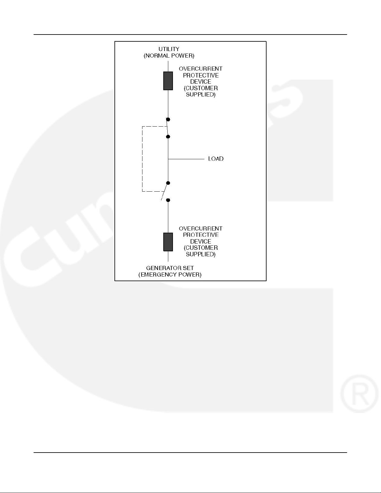
The load is connected to the common of the ATS (Figure 1). Under normal conditions, the load
is supplied with power from the utility (as illustrated). If utility power is interrupted, the load is
transferred to the generator set (genset). When utility power returns, the load is retransferred to
the utility. The transfer and retransfer of the load are the two most basic functions of a transfer
switch.
1.3 Transfer Switch Function
Automatic transfer switches, capable of automatic operation without operator intervention,
perform the basic function of transferring the load to the available power source. The controller
monitors each source for allowable voltage and frequency range.
This automatic transfer switch, capable of automatic operation without operator intervention, is
designed for utility-to-genset applications. In utility-to-genset applications, the transfer switch
performs the following functions:
1. Senses the interruption of utility power.
2. Sends a start signal to the genset.
3. Transfers the load to the genset.
4. Senses the return of utility power.
5. Retransfers the load to the utility.
6. Sends a stop signal to the genset.
962-0617 (Issue 5) 1
Page 8
1. Introduction 4-2010
FIGURE 1. LOAD TRANSFER SWITCH (TYPICAL FUNCTION)
1.4 Installation Overview
These installation recommendations apply to typical installations. Whenever possible, these
recommendations also cover factory designed options or modifications. However, because of
the many variables in any installation, it is not possible to provide specific recommendations for
every situation. If there are any questions not answered by this manual, contact your nearest
Cummins/Onan distributor for assistance.
1.4.1 Application and Installation
Installations must be carefully planned and correctly installed for proper operation. This involves
two essential elements: application and installation.
2 962-0617 (Issue 5)
Page 9

4-2010 1. Introduction
Application refers to the design of the complete standby power system that usually includes
power distribution equipment, transfer switches, ventilation equipment, mounting pads, cooling
systems, exhaust systems, and fuel systems. Each component must be correctly designed so
the complete system functions as intended. Application and design is an engineering function
generally done by specifying engineers or other trained specialists. Specifying engineers are
responsible for the design of the complete standby system and for selecting the materials and
products required.
Installation refers to the actual set-up and assembly of the standby power system. The
installers set up and connect the various components of the system as specified in the system
design plan. The complexity of the standby system normally requires the special skills of
qualified electricians, plumbers, sheet metal workers, etc. to complete the various segments of
the installation. This is necessary so all components are assembled using standard methods
and practices.
1.4.2 Safety Considerations
The transfer switch has been carefully designed to provide safe and efficient service when
properly installed, maintained, and operated. However, the overall safety and reliability of the
complete system depends on many factors outside the control of the manufacturer. To avoid
possible safety hazards, make all mechanical and electrical connections to the transfer switch
exactly as specified in this manual. All systems external to the transfer switch must comply with
all applicable codes. Make certain all required inspections and tests have been completed and
all code requirements have been satisfied before certifying the installation is complete and ready
for service.
Verify that both power source voltages match the nameplate rating prior to installation.
1.5 Model Identification
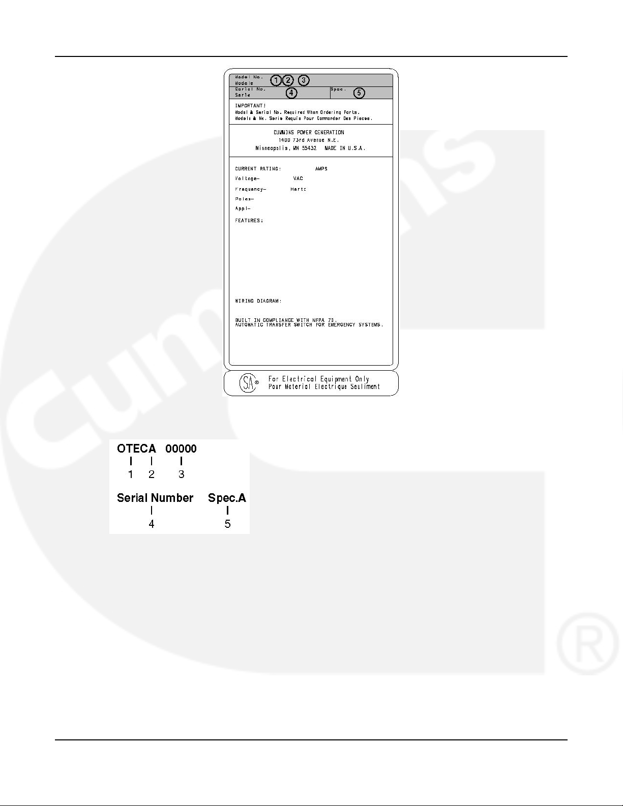
Identify your model by referring to the Model and Specification number as shown on the
nameplate. Electrical characteristics are shown on the lower portion of the nameplate (see
Figure 2), which is located on the cabinet door.
If it is necessary to contact a distributor regarding the transfer switch, always give the complete
Model, Specification, and Serial number. This information is necessary to properly identify your
unit among the many types manufactured.
962-0617 (Issue 5) 3
Page 10
1. Introduction 4-2010
FIGURE 2. NAMEPLATE
The model number is made up of code segments that designate various features or options:
1. OTEC - Open transition transfer switch
2. Ampere Rating:
A = 40, 70, 125
B = 150, 225, 260
C = 300, 400, 600
D = 800, 1000
E = 1200
3. Assigned spec number - issued for each specific combination of accessories, voltages,
frequency, and standards codes. This number is only repeated for standard product.
4. Serial Number - A unique number assigned to the transfer switch.
4 962-0617 (Issue 5)
Page 11

4-2010 1. Introduction
5. Specification letter - advances with production modification.
1.6 How to Obtain Service
When the transfer switch requires servicing, contact your nearest Cummins Power Generation
distributor. Factory-trained Parts and Service representatives are ready to handle all your
service needs.
To contact your local Cummins Power Generation distributor in the United States or Canada,
call 1-800-888-6626 (this automated service utilizes touch-tone phones only). By selecting
Option 1 (press 1), you will be automatically connected to the distributor nearest you.
If you are unable to contact a distributor using the automated service, consult the Yellow Pages.
Typically, our distributors are listed under:
Generators-Electric,
Engines-Gasoline or Engines-Diesel, or
Recreational Vehicles-Equipment,
Parts and Service.
For outside North America, call Cummins Power Generation, 1-763-574-5000, 7:30 AM to 4:00
PM, Central Standard Time, Monday through Friday. Or, send a fax to Cummins Power
Generation using the fax number 1-763-528-7229.
When contacting your distributor, always supply the complete Model, Specification, and Serial
Number as shown on the generator set nameplate.
962-0617 (Issue 5) 5
Page 12

1. Introduction 4-2010
This page is intentionally blank.
6 962-0617 (Issue 5)
Page 13
2 Mounting
2.1 Location
The location of the transfer switch in the existing electrical circuit varies with the application and
the type of entrance switch. The location and wiring must comply with the contract drawings.
There must be a service disconnect in the commercial power line ahead of the transfer switch.
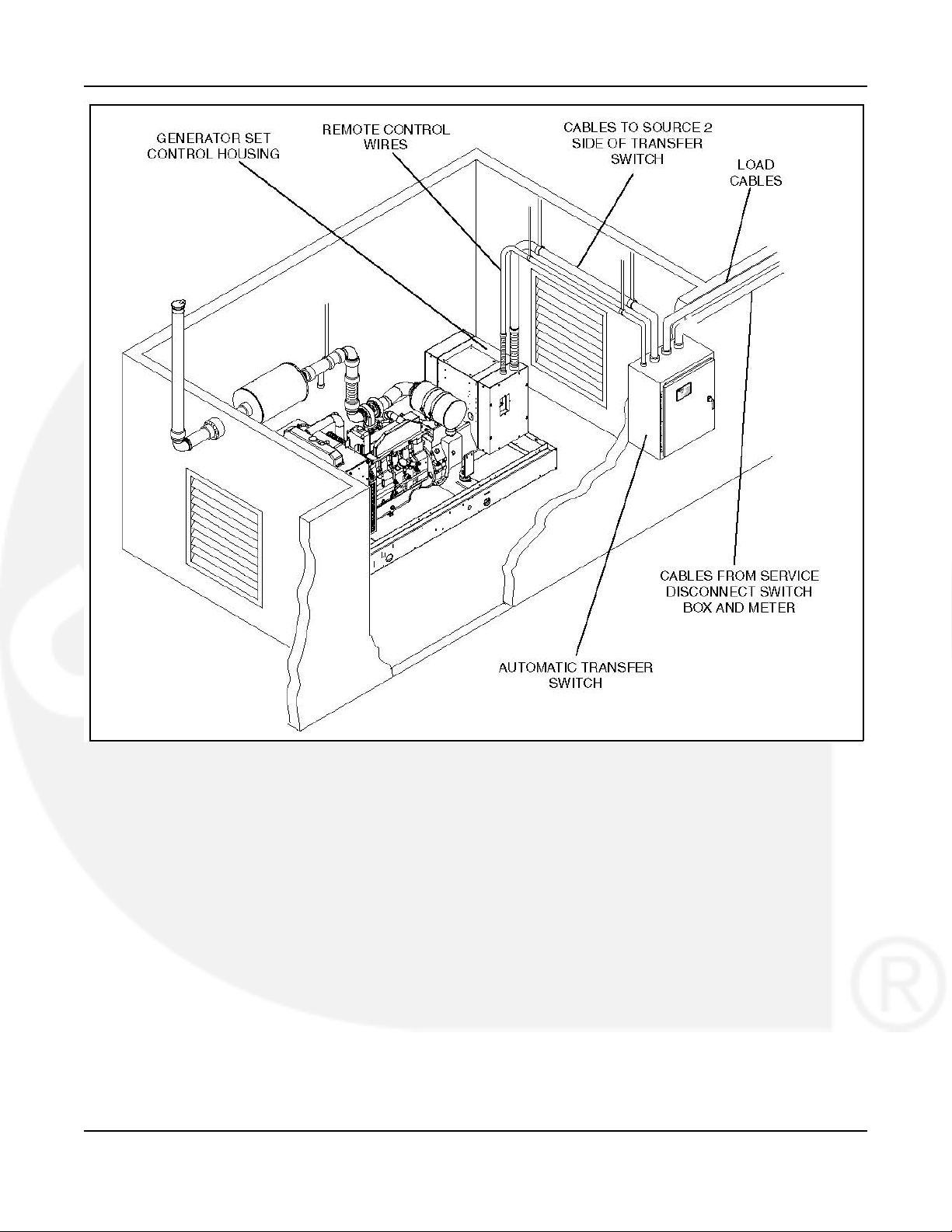
A typical installation is shown in Figure 3. Cabinet dimensions and weights are listed in Table 2,
Table 3, and Table 4.
Choose a vibration-free mounting surface that supports the weight of the switch. Avoid locations
that are near flammable liquids or gases, or are hot, moist, or dusty.
WARNING: An electrical arc occurs during transfer that can ignite a flammable
atmosphere, resulting in severe personal injury or death. The switch must
not be located near batteries, fuel tanks, solvents, or other sources of
flammable liquids or gases, or in areas sharing ventilation with such sources.
2.2 Wall Mounting
1. Check the location to be sure that no wires or plumbing, gas, or exhaust lines run behind
the wall.
2. Install two mounting bolts in the wall for the top cabinet mounting keyholes.
3. With the shipping box standing so the cabinet is upright, carefully remove the top and sides
of the box.
4. Raise the cabinet and mount it on the two mounting bolts in the wall.
WARNING: Improper lifting can cause severe personal injury. Have sufficient manpower
for lifting and mounting the cabinet.
5. Install two bottom mounting bolts, but do not tighten. (Do not remove the cabinet support
until all bolts are installed.)
6. Push the cabinet against the wall. If the cabinet does not align flush against the wall, shim
the mounting bosses as required.
7. Tighten all mounting bolts.
TABLE 2. APPROXIMATE NEMA 1 CABINET DIMENSIONS
Switch Current
Rating
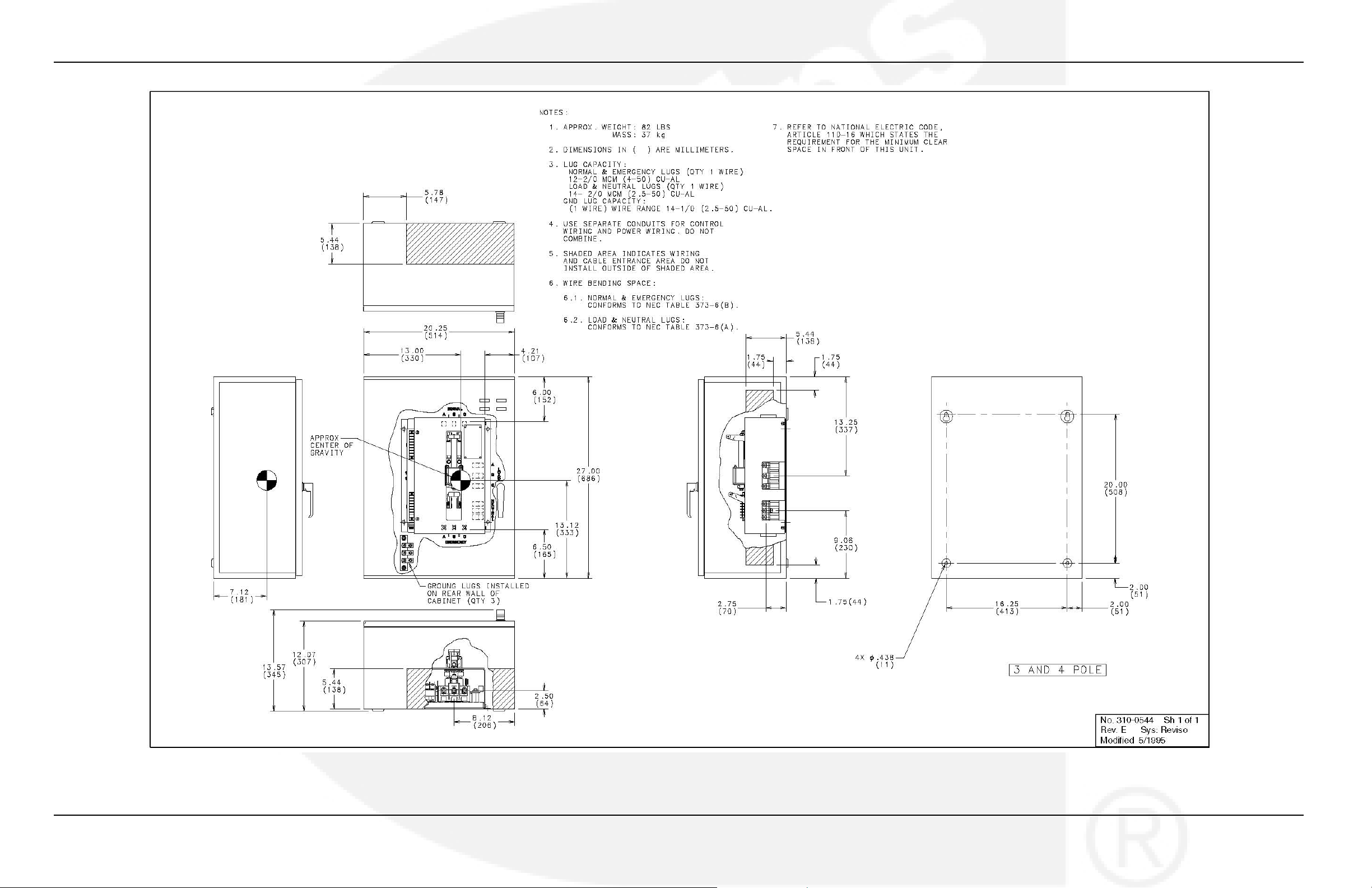
40, 70, & 125 27 in 20.25 in 13.6 in 31.5 82 lb
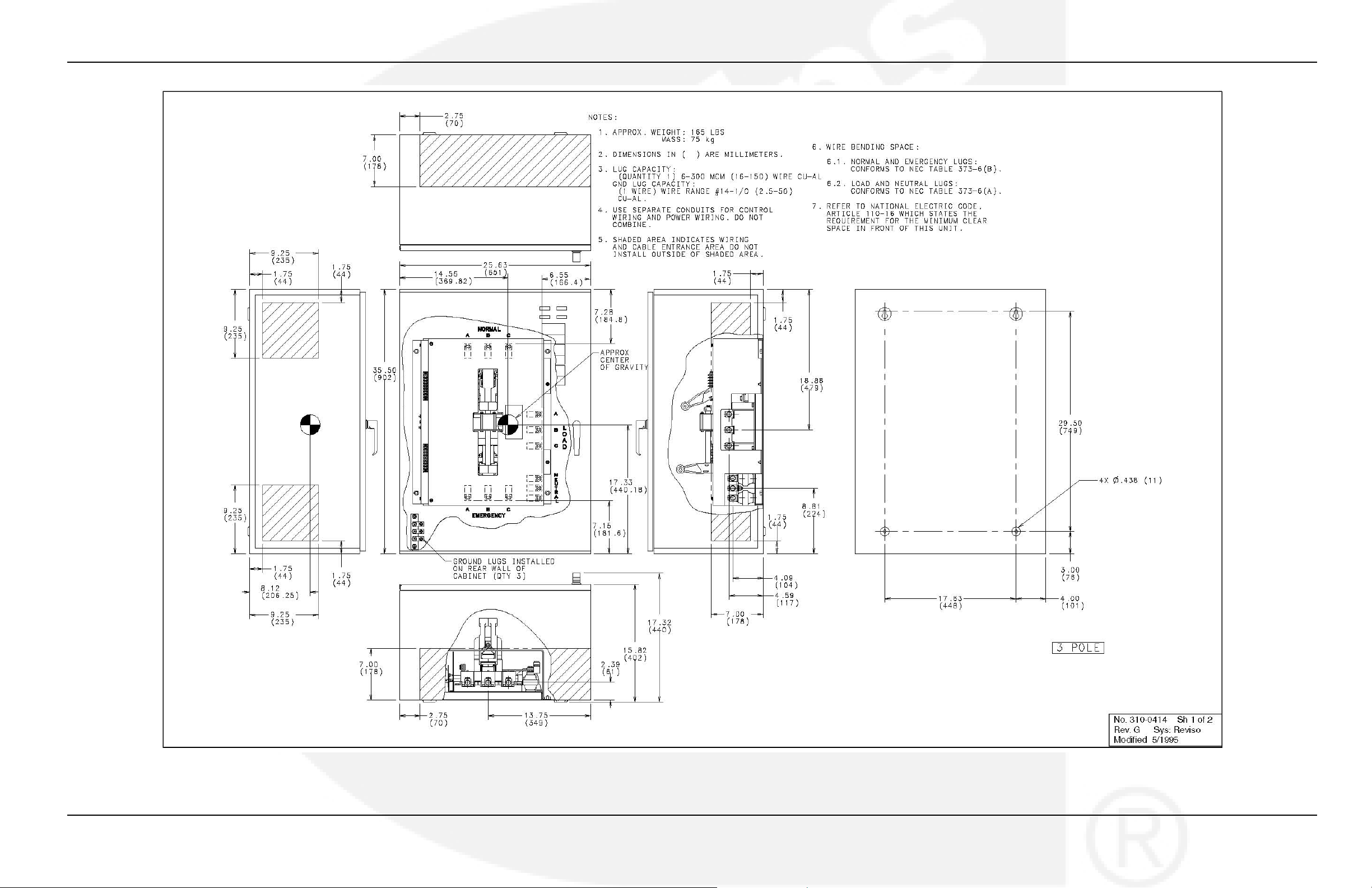
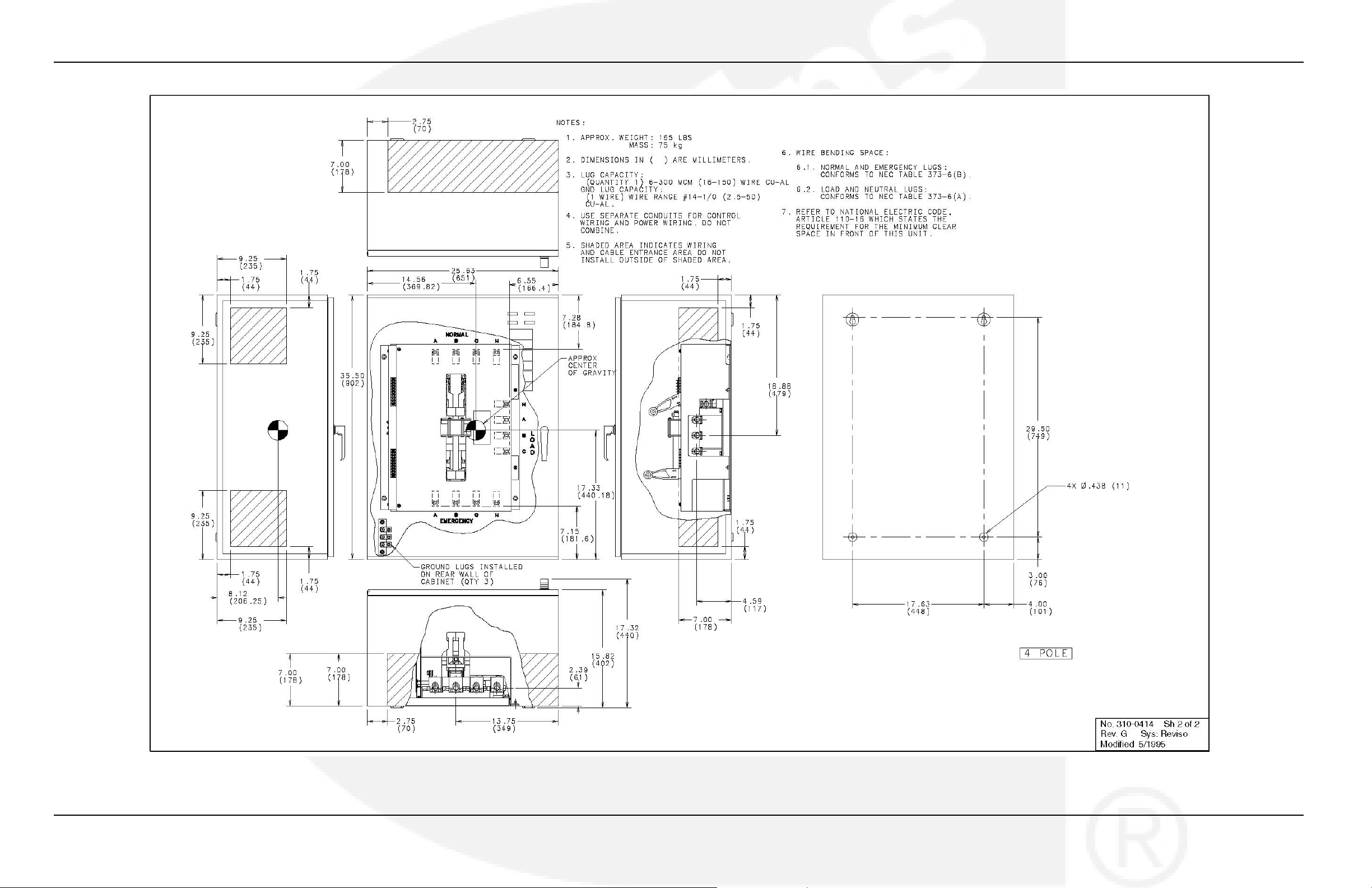
150 & 225 35.5 in 25.6 in 17.3 in 40.6 in 165 lb
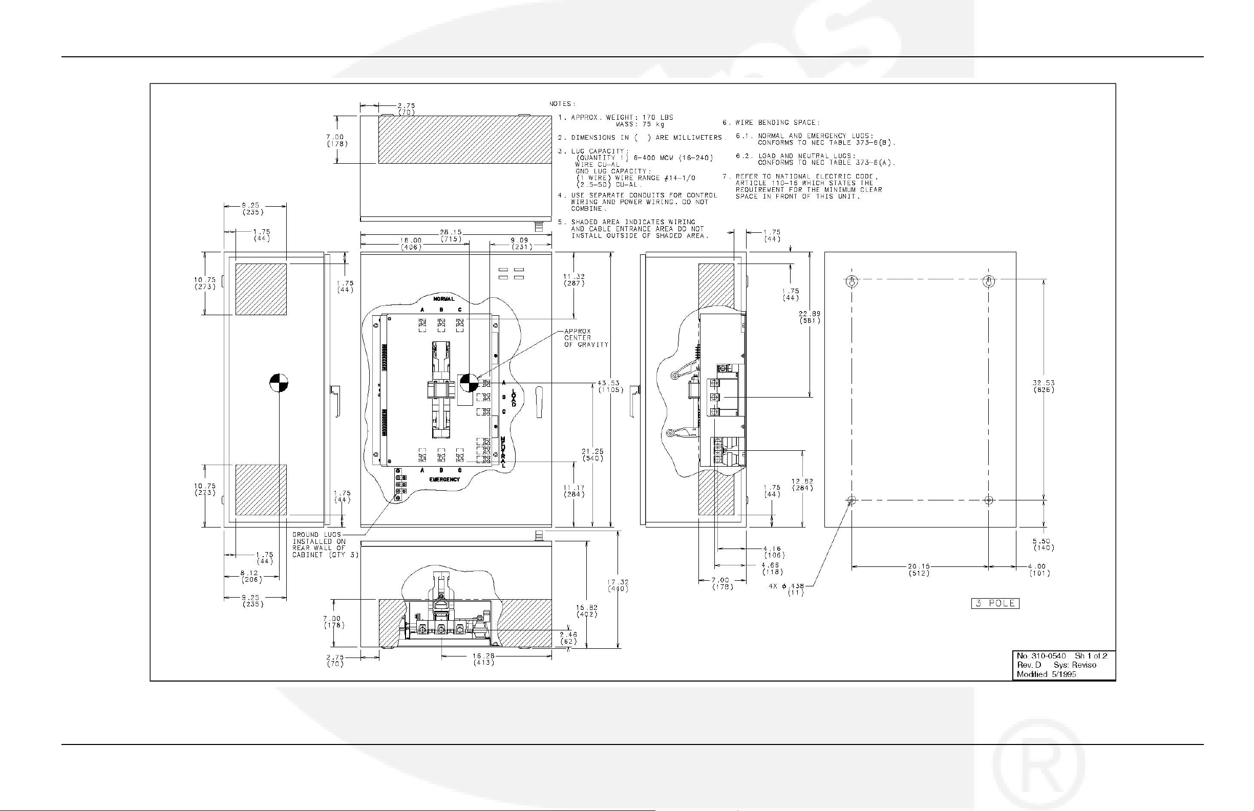
260 43.5 in 28.2 in 17.3 in 43.2 in 170 lb
Height Width Weight
686 mm 514 mm 345 mm 800 mm 37 kg
902 mm 651 mm 440 mm 1032 mm 74.25 kg
1105 mm 715 mm 440 mm 1096 mm 76.5 kg
Depth With Door
Closed Open
962-0617 (Issue 5) 7
Page 14
2. Mounting 4-2010
Switch Current
Rating
300, 400, & 600 53.8 in 25.2 in 19.6 in 42.2 in 225 lb
800 & 1000 67.6 in 30 in 20.6 in 48.4 in 360 lb
1200 90 in 39 in 27.5 in 65 in 730 lb
Height Width Weight
1367 mm 639 mm 497 mm 1071mm 101.25 kg
1718 mm 762 mm 524 mm 1227 mm 162 kg
2286 mm 991 mm 698 mm 1644 mm 331 kg
Depth With Door
Closed Open
TABLE 3. APPROXIMATE NEMA 3R AND 12 CABINET DIMENSIONS
Switch Current
Rating
40, 70, & 125 33.8 in 26.25 in 13.75 in 36.7 in 125 lb
150 & 225 42.3 in 30.4 in 17.6 in 44.4 in 190 lb
260 45.75 in 32 in 17.6 in 46 in 200 lb
300, 400, & 600 58.7 in 27.5 in 20.2 in 43.9 in 290 lb
800 & 1000 73.5 in 32.3 in 20.8 in 49.75 in 410 lb
1200 90 in 39 in 27.5 in 65 in 730 lb
Height Width Weight
859 mm 667 mm 350 mm 931 mm 56.3 kg
1075 mm 771 mm 447 mm 1129 mm 85.5 kg
1162 mm 814 mm 447 mm 1170 mm 90 kg
1491 mm 697 mm 512 mm 1113 mm 130.5 kg
1867 mm 821 mm 529 mm 1263 mm 184.5 kg
2286 mm 991 mm 698 mm 1644 mm 331 kg
Depth with Door
Closed Open
TABLE 4. APPROXIMATE NEMA 4 CABINET DIMENSIONS
Switch Current
Rating
40, 70, & 125 33.8 in 26.25 in 13.75 in 37.4 in 125 lb
150 & 225 42.3 in 30.4 in 17.6 in 45.1 in 190 lb
260 45.75 in 32 in 17.6 in 46.7 in 200 lb
300, 400, & 600 58.7 in 27.5 in 20.2 in 44.625 in 290 lb
800 & 1000 73.5 in 32.3 in 20.8 in 50.45 in 410 lb
1200 90 in 39 in 27.5 in 65 in 730 lb
Height Width Weight
859 mm 667 mm 350 mm 949 mm 56.3 kg
1075 mm 771 mm 447 mm 1147 mm 85.5 kg
1162 mm 814 mm 447 mm 1188 mm 90 kg
1491 mm 697 mm 512 mm 1131 mm 130.5 kg
1867 mm 821 mm 529 mm 1281 mm 184.5 kg
2286 mm 991 mm 698 mm 1644 mm 331 kg
Depth with Door
Closed Open
8 962-0617 (Issue 5)
Page 15
4-2010 2. Mounting
FIGURE 3. TYPICAL WALL-MOUNT INSTALLATION
2.3 Seismically Certified Installations
Seismically certified transfer switch installations (feature code A080-7) have special
requirements, as defined by IAA-VMC (Independent Approval Agency, the VMC Group).
1. The design of post-installed anchors in concrete used for the component anchorage; is
prequalified for seismic applications in accordance with AC1 355.2 and documented in a
report by a reputable testing agency (for example, the Evaluation Service Report issued by
the international Code Council).
2. Anchors must be installed to an embedment depth, as recommended in the prequalification
test report defined in Note 1. For IBC 2000 and IBC 2003 applications, the minimum
embedment must be 8 times the anchor diameter.
962-0617 (Issue 5) 9
Page 16

2. Mounting 4-2010
3. Anchors must be installed in a minimum of 4000 PSI compressive strength normal weight
concrete. Concrete aggregate must comply with ASTM C33. Installation in structural
lightweight concrete is not permitted unless otherwise approved by the structural engineer
of record.
4. Anchors must be installed to the maximum torque specification, as recommended by the
anchor manufacturer.
5. Anchors must be installed in the locations specified on the Installation Outline Drawings or
on Seismic Requirements Installation Drawing 0179-5288.
6. Wide washers must be installed at each anchor location between the anchor head and the
equipment for tension load distribution. Wide steel washers must be Series W of American
National Standard Type A plain washers flow carbon steel washers), ANSI B18.22.1- 1965,
R1975, with the washer sizes specified on drawing 0179-5288 (Switch Installation; Seismic
Requirements, sheet 2 of 3).
7. Concrete floor slab and concrete housekeeping pads must be designed and
rebar-reinforced for seismic applications, in accordance with ACI 318.
8. All housekeeping pad thicknesses must be designed in accordance with the prequalification
test report, as defined in Note 1 or a minimum of 1.5 times the anchor embedment depth,
whichever is largest.
9. All housekeeping pads must be dowelled or cast into the building structural floor slab and
designed for seismic application, as per SCI 318 and as approved by the structural
engineer of record.
10. Wall mounting equipment must be installed to a rebar-reinforced structural concrete wall
that is seismically designed and approved by the engineer of record to resist the added
seismic loads from components being anchored to the wall.
11. Floor mounted equipment (with or without a housekeeping pad) must be installed to a
rebar-reinforced structural concrete floor that is seismically designed and approved by the
engineer of record to resist the added seismic leads from components being anchored to
the floor.
12. When installing to a floor or wall, rebar interference must be considered.
13. Attaching seismic certified equipment to any floor ar wall, other than those constructed of
structural concrete and designed to accept the seismic loads from said equipment, is not
permitted by this specification.
14. Attaching seismic certified equipment to any floor constructed of light weight concrete over
steel decking is not permitted by this specification.
15. Attaching seismic certified equipment to any concrete bock walls or cinder block walls is
not permitted by this specification.
For special switch installation requirements, see written and tabulated seismic
requirements listed on drawing 0179-5288.
The installation of the seismically certified switch should be overseen by the installation project
structural engineer of record.
The Site Specific Requirements listed on page one of the "Seismic Certificate of Compliance"
should be filled out by the installation project structural engineer of record.
Drawing 0179-5288 and the Seismic Certificate of Compliance for transfer switch and seismic
installation requirements are included in the literature package of each seismically certified
switch with feature code A080-7.
10 962-0617 (Issue 5)
Page 17

3 Wiring
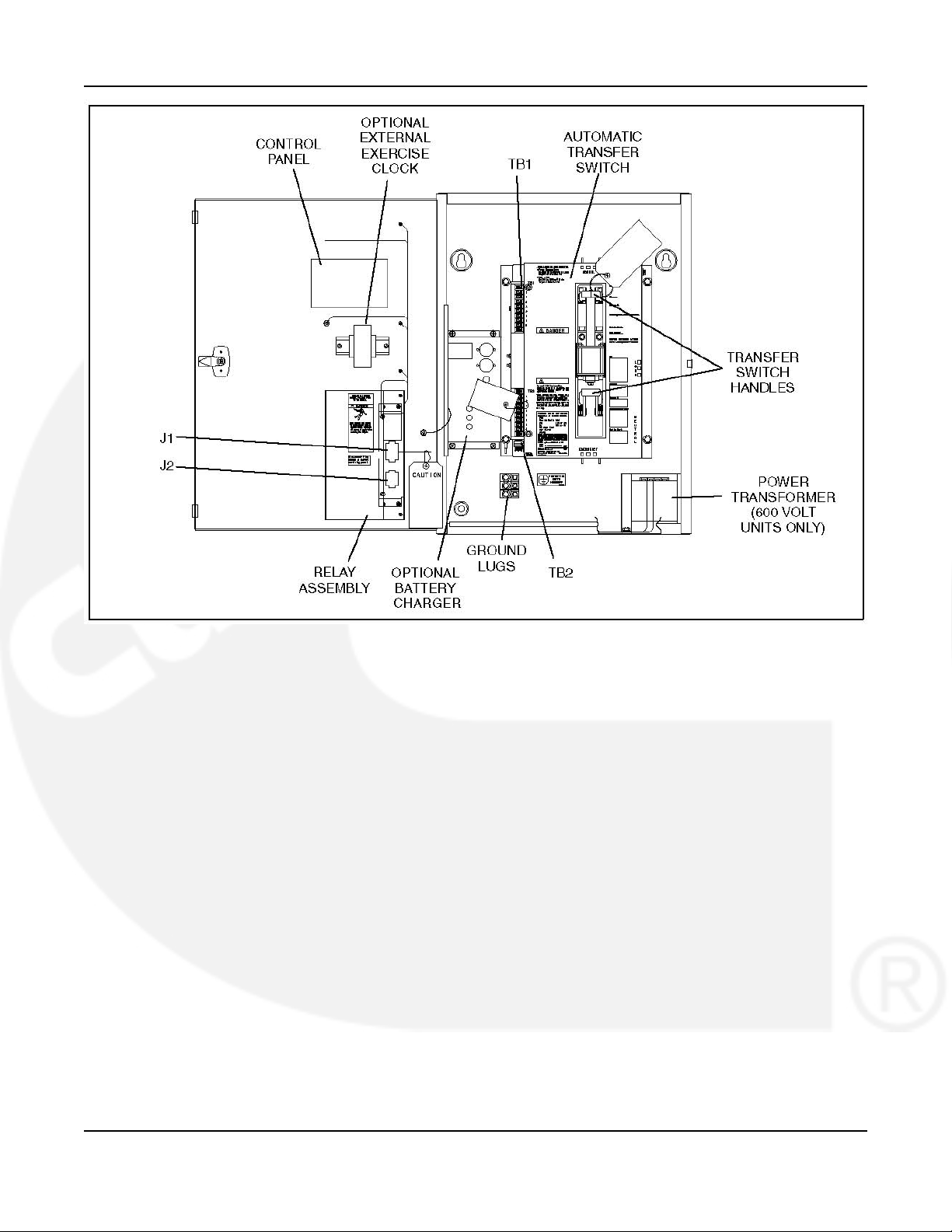
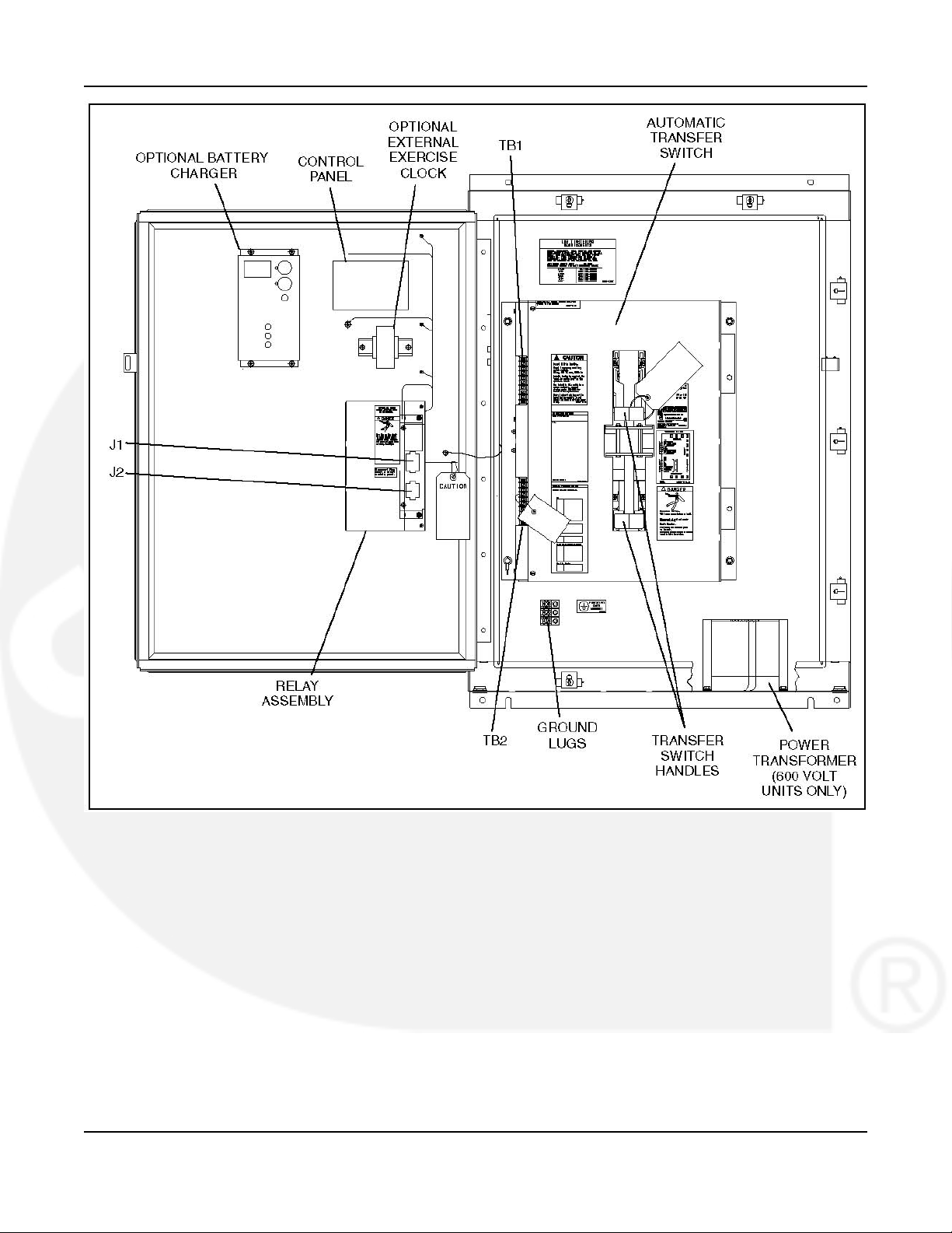
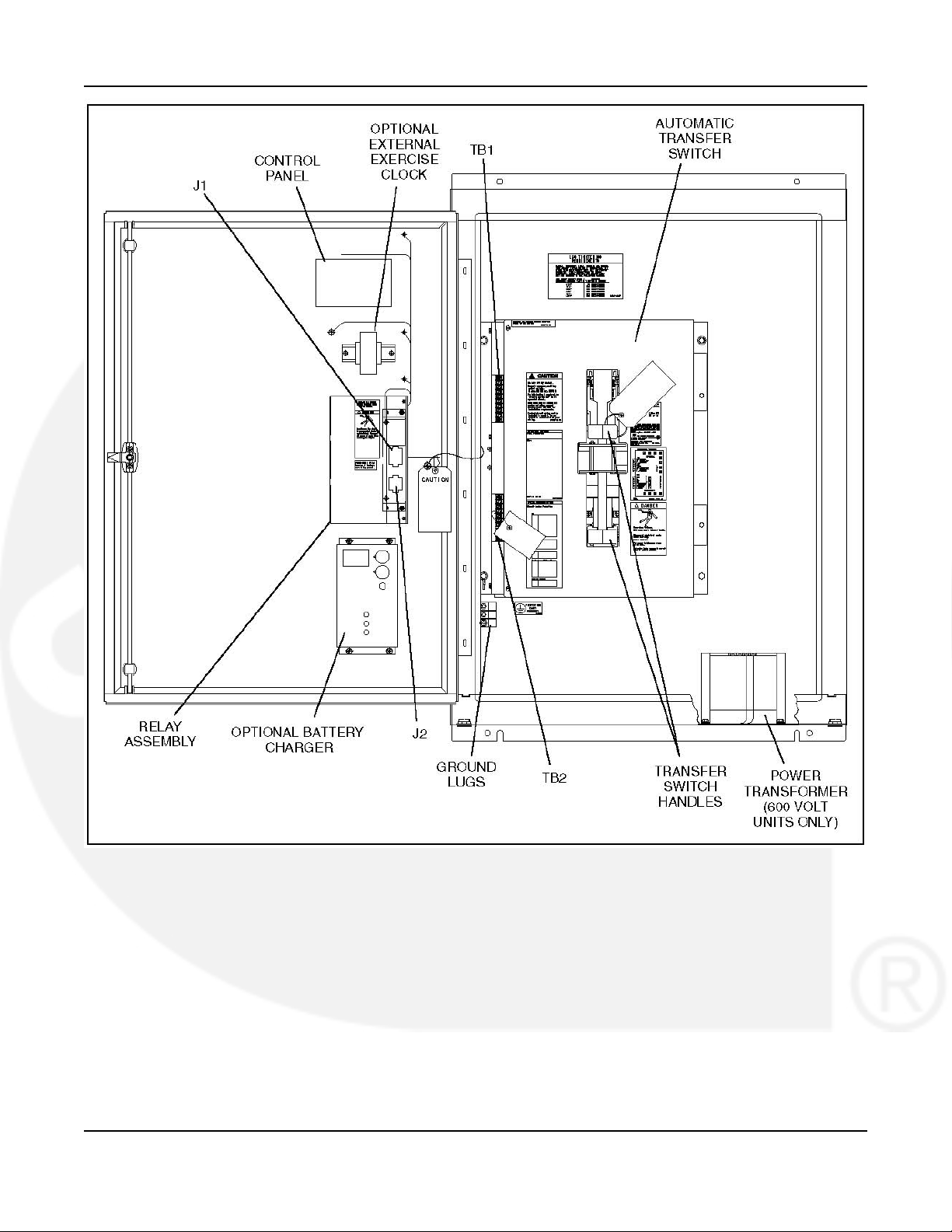
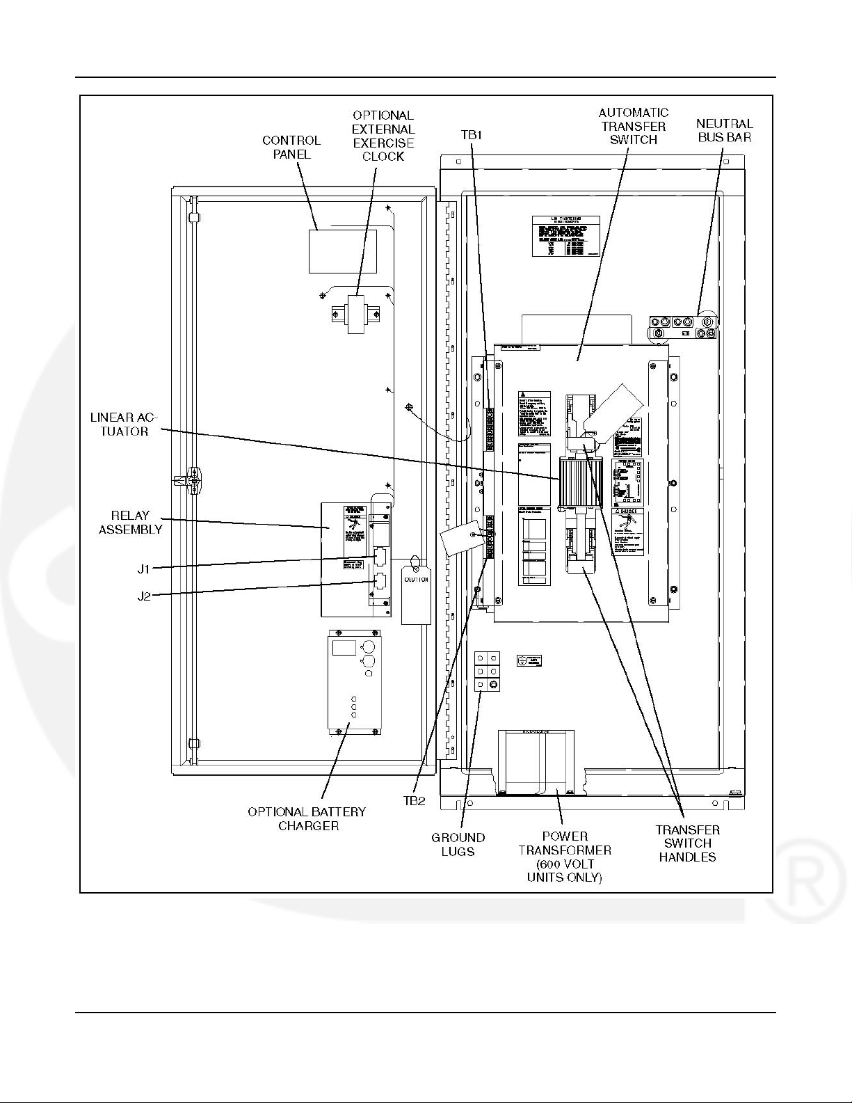
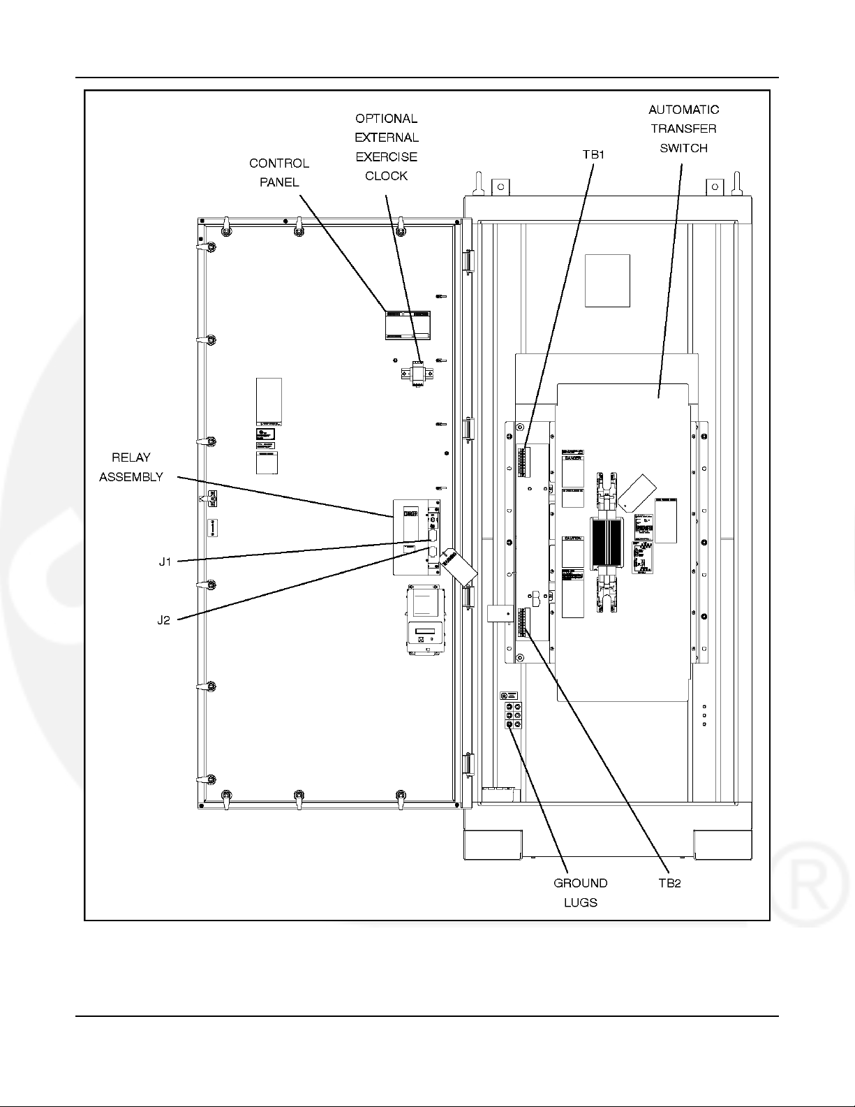
Refer to Figure 4 thru Figure 8 for component locations.
WARNING: AC voltages and currents present an electrical shock hazard that can cause
severe personal injury or death. Only trained and experienced personnel are
to perform the following procedures.
When installing conduit, observe the following precautions:
1. Before beginning conduit installation, cover the transfer switch to prevent accidental
entry of metal chips.
2. If using rigid conduit between the generator set and the transfer switch, install at least 2
feet (610 mm) of flexible conduit between the rigid conduit and generator set to absorb
vibration.
3. Run control circuit wiring in separate conduit from the AC wiring; otherwise, induced
currents could cause operational problems within the switch. Cutouts can be made through
the top, bottom, or sides of the cabinet. (Refer to the switch outline drawings included in
Appendix A.)
CAUTION: Installation debris can cause equipment failure and damage. Use extreme care to
keep drill chips and filings out of the relays, contacts, and other parts of the
automatic transfer switch when mounting or connecting conduit. Screwdrivers
should be used carefully to prevent damage to components.
962-0617 (Issue 5) 11
Page 18
3. Wiring 4-2010
FIGURE 4. INTERIOR/COMPONENTS: 40-125 AMP SWITCH, TYPE 1 CABINET
12 962-0617 (Issue 5)
Page 19
4-2010 3. Wiring
FIGURE 5. INTERIOR/COMPONENTS: 150-225 AMP SWITCH, TYPE 4 CABINET
962-0617 (Issue 5) 13
Page 20
3. Wiring 4-2010
FIGURE 6. INTERIOR/COMPONENTS: 260 AMP SWITCH, TYPE 3R AND 12 CABINET
14 962-0617 (Issue 5)
Page 21
4-2010 3. Wiring
FIGURE 7. INTERIOR/COMPONENTS: 300-600 AMP SWITCH, TYPE 3R AND 12 CABINET (800-1000
AMP SIMILAR)
962-0617 (Issue 5) 15
Page 22
3. Wiring 4-2010
FIGURE 8. INTERIOR/COMPONENTS: 1200 AMP SWITCH, TYPE 1, 3R, 4, 4X CABINET
16 962-0617 (Issue 5)
Page 23
4-2010 3. Wiring
3.1 Recommended Compression Lugs (OTECE Spec A)
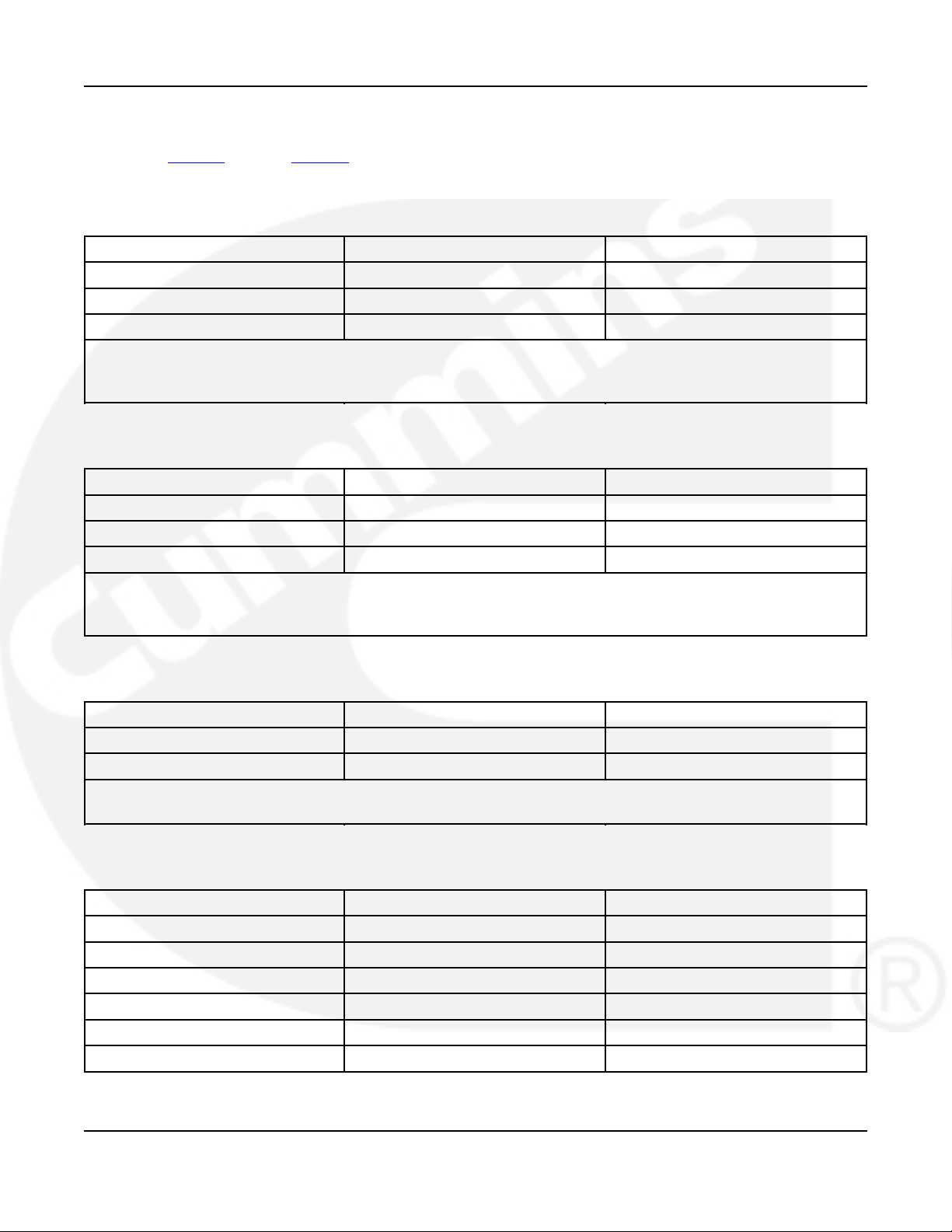
Table 5 through Table 8 list recommended compression lugs in sizes 500, 600, and 750 MCM
for the OTECE Spec A switch.
TABLE 5. COMPRESSION LUGS FROM ILSCO
750 MCM 600 MCM 500 MCM
CRA-750L2 CRA-600L2 CRA-500L2
2ACL-750 2ACL-600 2ACL-500
2IACL-750 2IACL-600 2IACL-500
CRA-xxxL2 represents long barrel copper compression lugs.
2ACL-xxx represents aluminum compression lugs.
2IACL-xxx represents narrow tang aluminum compression lugs.
TABLE 6. COMPRESSION LUGS FROM THOMAS & BETTS (COLOR-KEYED)
750 MCM 600 MCM 500 MCM
54223 54289 54286
60278 60275 60273
60278N 60278N 60278N
54xxx represents short barrel two hole lugs.
60xxx represents two hole lugs - 90° C.
60xxxN represents range taking narrow tongue single barrel lugs. The 60278N lug is from 500 to 750 MCM.
TABLE 7. COMPRESSION LUGS FROM THOMAS & BETTS ( BLACKBURN)
750 MCM 600 MCM 500 MCM
LCN75 LCN600 LCN500
ATL502 ATL6002 ATL5002
LCN represents long barrel 2-hole mount copper lugs.
ATL represents 2-hole aluminum lugs.
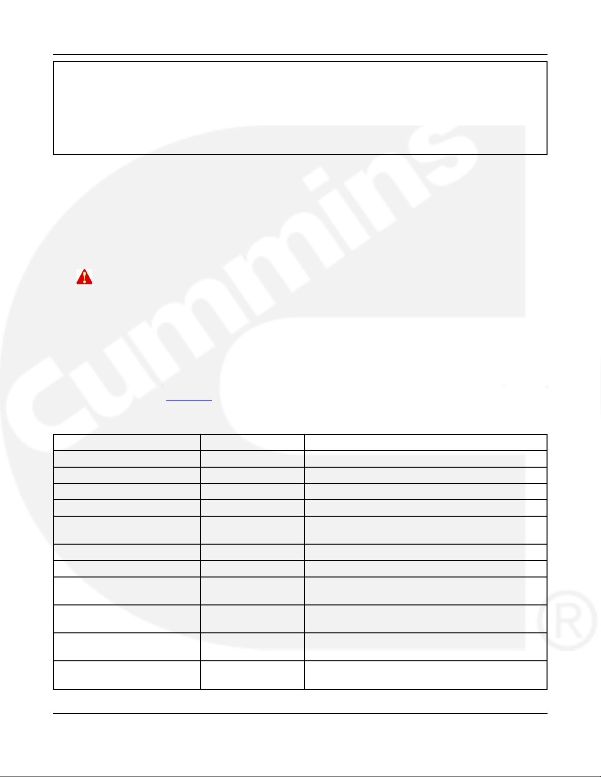
TABLE 8. COMPRESSION LUGS FROM BURNDY
750 MCM 600 MCM 500 MCM
YA39-2LN YA36-2LN YA34-2LN
YA39-2N YA36-2N YA34-2N
YA44L-2NTC-FX - YA38L-2NTC-FX
YAG44L-2NTC-LD - YAG38L-2NTC-LD
YA44-2N-FXB - YA38-2N-FXB
YA39A5 and YA39AM2 YA36A3 YA34A3
962-0617 (Issue 5) 17
Page 24
3. Wiring 4-2010
YAxx-2LN represents standard length barrel copper compression terminal.
YAxx-2N represents long barrel uninsulated copper compression terminal.
YAxxL-2NTC-FX represents standard length barrel copper compression terminal for flexible and extra flexible copper
cables.
YAGxxL-2NTC-LD represents standard length barrel lead plated copper compression terminal.
YAGxx-2N-FXB represents long barrel copper compression terminal belled entry for flexible and extra flexible copper
cables.
YAxxAx and YAxxAMx represent 2-hole and 4-hole uninsulated aluminum compression terminal.
3.2 AC Connections
Perform wiring in the following sequence:
1. Test the operation of the generator set from its own controls.
2. Stop the generator set and remove the negative lead from the cranking battery to prevent
starting.
WARNING: Failure to prevent the generator set from starting before wiring procedures
are performed presents a shock hazard that can cause severe personal injury
or death. Disconnect generator set battery (negative (-) terminal first) before
proceeding.
3. Connect conductors of sufficient size (see contract drawings) to carry rated current from
the line, load, and generator set directly to the transfer switch terminals, which are marked
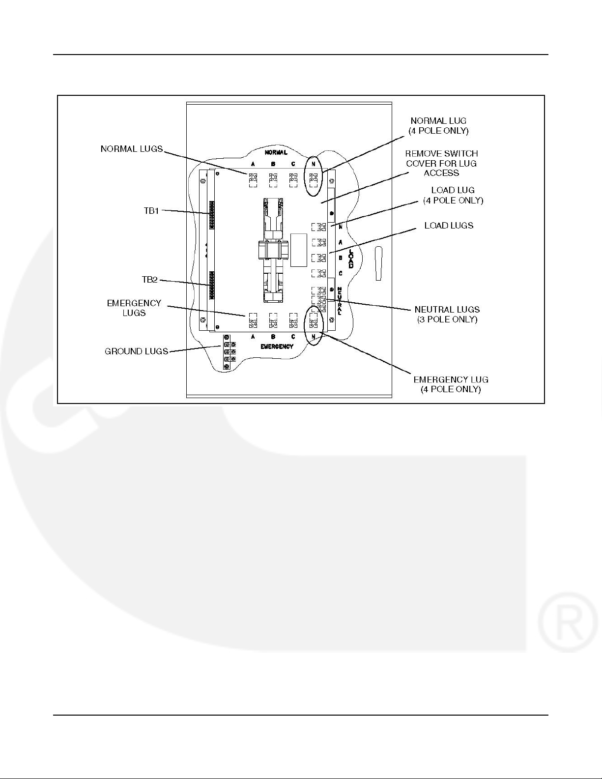
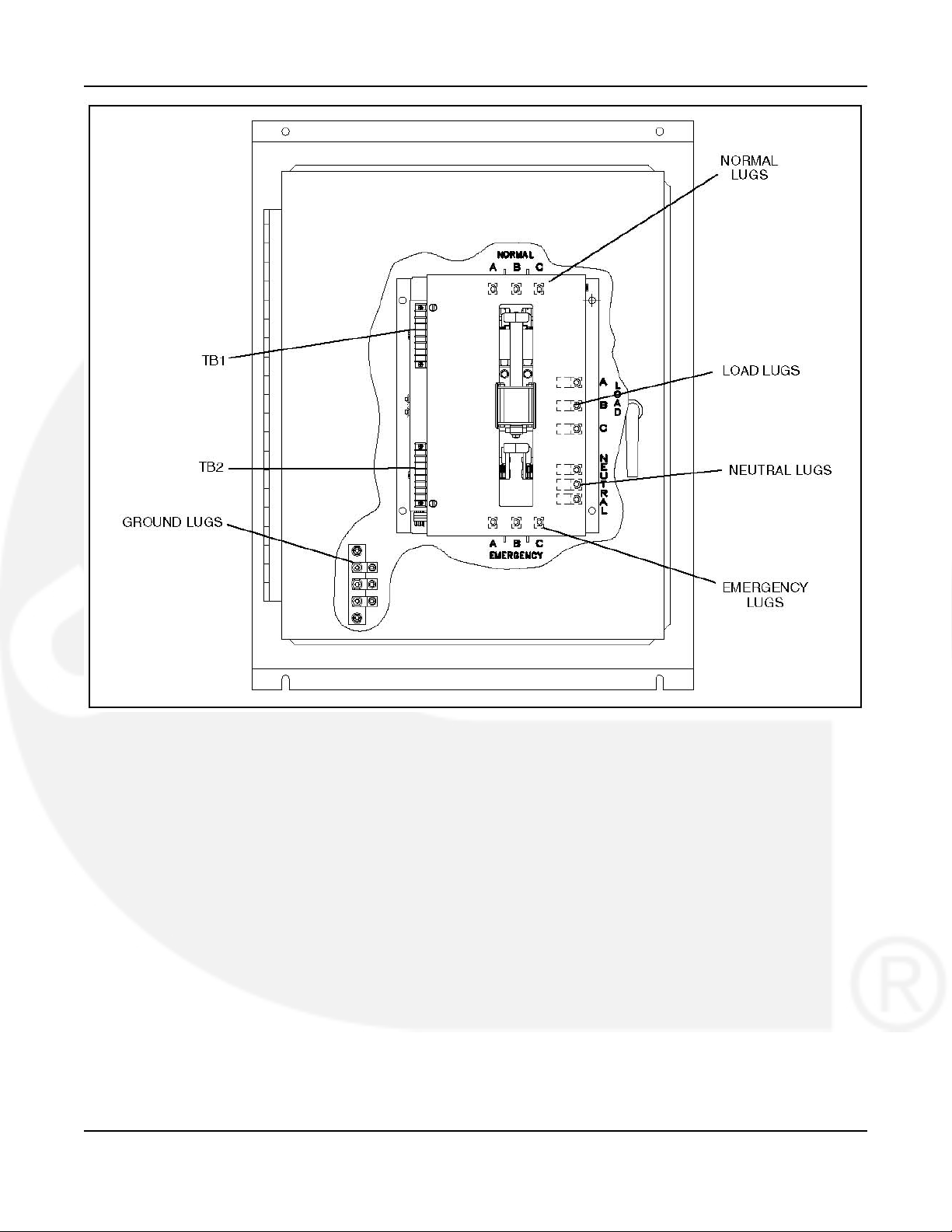
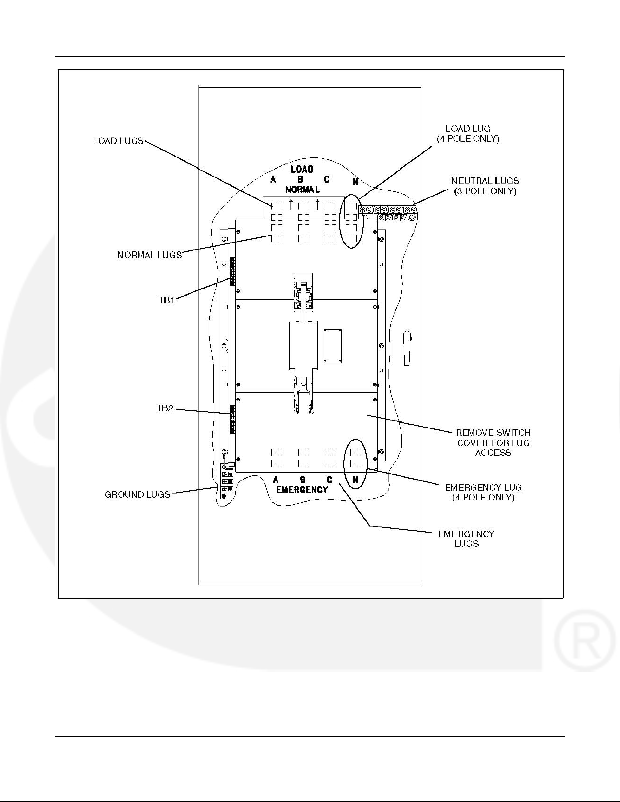
A, B, and C (A, B, C, and N on 4-pole switches). A neutral bar with lugs is standard on
3-pole switches. Phase rotation must be the same on the utility and genset power sources.
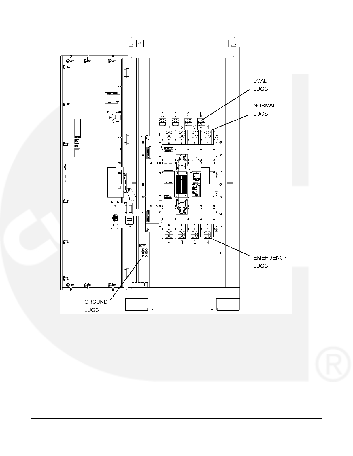
Table 9 gives the type and maximum conductor size the transfer switch accepts. Figure 9
through Figure 12 show transfer switch source and load connections.
TABLE 9. TERMINAL LUG CAPACITY FOR COPPER OR ALUMINUM CONDUCTORS
Switch Current Rating Wires per Phase Size Range of Wires
40/70/125 Source 1 12 AWG-2/0 Cu-Al
40/70/125 Load & Neutral 1 14 AWG-2/0 Cu-Al
150/225 1 6 AWG-300 MCM Cu-Al
260 1 6 AWG-400 MCM Cu-Al
300/400 2 3/0 AWG-250 MCM Cu-Al
1 3/0 AWG-600 MCM Cu-Al
600 2 250-500 MCM Cu-Al
800/1000 4 250-500 MCM Cu-Al
1200 4 2 AWG-600 MCM Cu-Al
(standard - mechanical lugs)
1200 4 4-1/0-750 MCM Cu-Al
(optional - mechanical lugs)
1200 4 500 MCM Cu-Al
(optional - compression lugs)
1200 4 600 MCM Cu-Al
(optional - compression lugs)
18 962-0617 (Issue 5)
Page 25
4-2010 3. Wiring
Switch Current Rating Wires per Phase Size Range of Wires
1200 4 750 MCM Cu-Al
(optional - compression lugs)
4. On 120-volt switches, connect the hot side to the (A) lug and the neutral side to the Neutral
lug. On 240-volt single phase switches, connect the two hot lines to the A- and C-lugs and
the Neutral line to the Neutral lug.
5. Connect power cables to the load terminals. Tighten the lugs as indicated in Table 10.
TABLE 10. LUG TORQUES
Set Screw Socket Size (Across Flats) Minimum Torque For Proper Operation
3/16 In 80 In-lbs (9 N·m)
1/4 In 200 In-lbs (23 N·m)
5/16 In 275 In-lbs (31 N·m)
3/8 In 375 In-lbs (43 N·m)
1/2 In 500 In-lbs (57 N·m)
9/16 In 600 In-lbs (68 N·m)
WARNING: AC voltages and currents present an electrical shock hazard that can cause
severe personal injury or death. Make sure that both AC power sources are
disconnected.
6. Make sure that both AC power sources are disconnected.
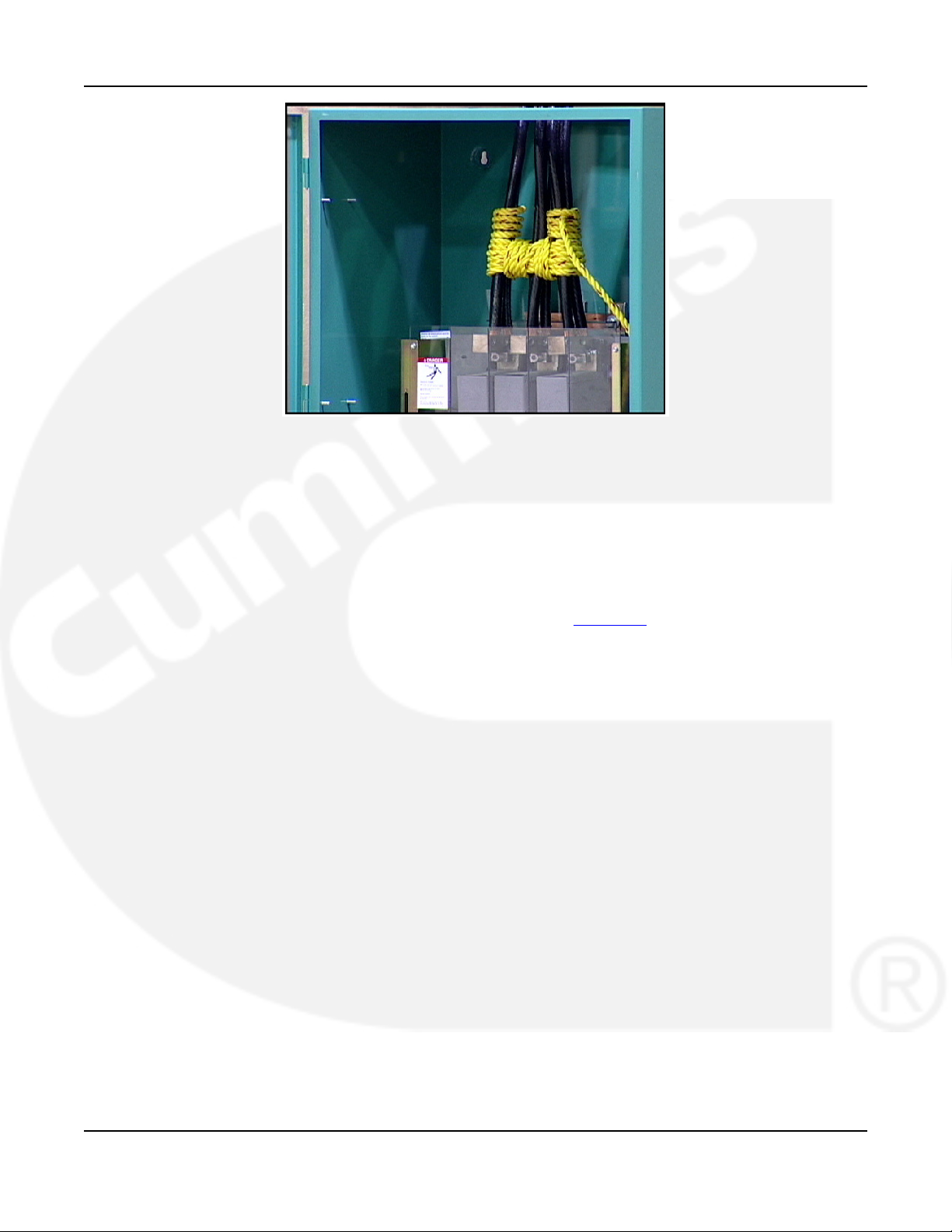
7. For 800-1000 amp transfer switches used on a circuit capable of delivering 50,000 amps @
600 volts, wrap the line cables together with nominal 1/2-inch nylon rope, or rope having a
minimum tensile strength of 4200 pounds, at five inches from the line terminals with four
wraps (see Figure 13).
962-0617 (Issue 5) 19
Page 26
3. Wiring 4-2010
FIGURE 9. 150-260 AMPERE, 4 POLE TRANSFER SWITCH TERMINAL LUG ACCESS, TYPE 1
CABINET (3 POLE, TYPE 3R, 4, AND 12 CABINETS ARE SIMILAR)
20 962-0617 (Issue 5)
Page 27
4-2010 3. Wiring
FIGURE 10. 40-125 AMPERE, 3 POLE TRANSFER SWITCH TERMINAL ACCESS (TYPE 3R AND 12
CABINET SHOWN - TYPE 1 AND 4 ARE SIMILAR)
962-0617 (Issue 5) 21
Page 28
3. Wiring 4-2010
FIGURE 11. 300-1000 AMPERE, 3 AND 4 POLE TRANSFER SWITCH TERMINAL LUG ACCESS (800
AMP TYPE 1 CABINET SHOWN - OTHERS ARE SIMILAR)
22 962-0617 (Issue 5)
Page 29
4-2010 3. Wiring
FIGURE 12. 1200 AMPERE, 4 POLE TRANSFER SWITCH TERMINAL LUG ACCESS
962-0617 (Issue 5) 23
Page 30
3. Wiring 4-2010
FIGURE 13. SECURE THE POWER CABLES
3.3 Control Connections
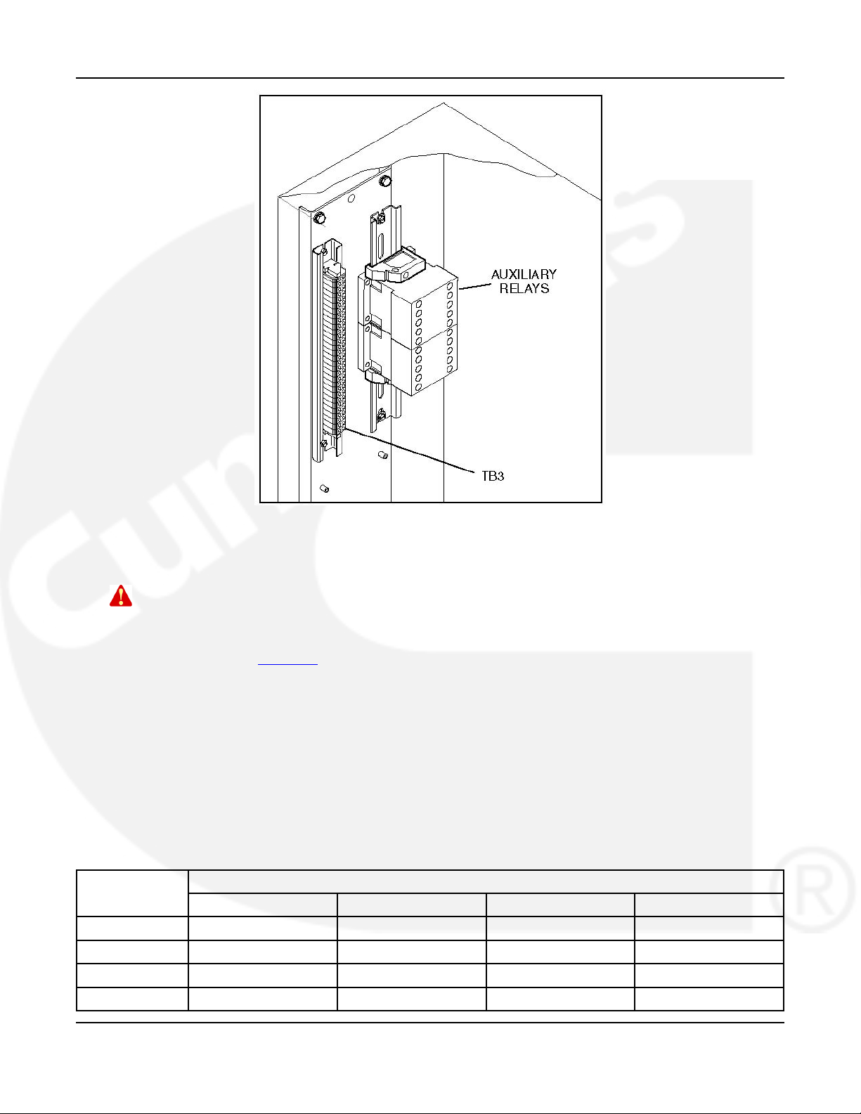
Connections of standard and optional control wiring are made at terminal blocks TB1, TB2, and
TB3; and directly at the (optional) auxiliary relays.
TB1 is located near the top left side on the front of the transfer switch. TB2 is located below
TB1, near the bottom left side of the transfer switch. TB3 and auxiliary relays are located inside,
on the upper left wall of the cabinet on the DIN rail (see Figure 14).
24 962-0617 (Issue 5)
Page 31
4-2010 3. Wiring
FIGURE 14. CONTROL WIRING CONNECTIONS
3.3.1 Connecting Transfer Switch to Genset
WARNING: AC voltages and currents present an electrical shock hazard that can cause
severe personal injury or death. Disconnect the AC power source.
Wire size depends on the distance and the type of battery charger installed in the transfer
switch. Refer to Table 11 to determine the wire size required.
· Use Column A for connections to TB2-2, 4, 5, 6, 7, 8, and, if equipped, the annunciator.
· Use Column B for connections to TB2-1 (GND) and TB2-3 (B+) if no battery charger is
installed in the transfer switch.
· Use Column C for connections to TB2-1 (GND) and TB2-3 (B+) if a 2-Amp battery charger
is installed in the transfer switch.
· Use Column D for connections to TB2-1 (GND) and TB2-3 (B+) if a 10-Amp battery
charger is installed in the transfer switch.
TABLE 11. WIRE SPECIFICATIONS
Wire Size
(AWG)
16 1000 425 125 25
14 1600 675 200 40
12 2400 1080 300 60
10 4000 1715 500 100
Column A Column B Column C Column D
Distance in Feet, One Way (Multiply by 0.3 for Meters)
962-0617 (Issue 5) 25
Page 32
3. Wiring 4-2010
Wire resistance must not exceed 0.5 ohm per line. Use stranded wire only. For connection to
the screw terminal, strip the insulation back 3/8 inch (10 mm).
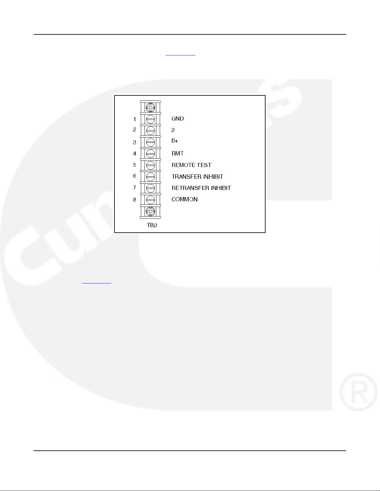
Remote starting (for Cummins Power Generation water-cooled generator sets only) uses
terminals B+, GND (ground), and RMT of terminal block TB2 (Figure 16). Connect these
terminals to like terminals on the generator set. Refer to Interconnect Wiring diagram shipped
with the switch. A jumper is shipped with the transfer switch and is in a small envelope attached
to TB2.
· For PCC 3100 and PCC 2100 genset controls, install a jumper between TB2-1 and TB2-2
for ground-to-start connection.
· For Detector 12 genset controls, install a jumper between TB2-2 and TB21-3 for B+ start.
· For PCC 3200 genset controls requiring a dry contact start, do not install a jumper.
Be sure to check the Interconnect Wiring diagram shipped with the transfer switch.
3.3.2 Auxiliary Contacts
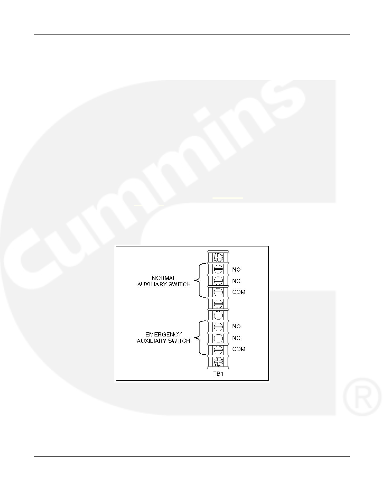
Auxiliary contacts, for external alarm or control circuitry, are available for the Normal (utility
power) and Emergency (genset power) sides of the transfer switch. Connections for the auxiliary
contacts can be made on terminal block TB1 (Figure 15). The contacts have ratings of 10
amperes at 250 VAC. Figure 15 shows the normally open and normally closed positions of the
auxiliary contacts with the transfer switch in the neutral position. Moving the transfer switch to
Normal or Emergency actuates the corresponding auxiliary contacts.
Use number 22 to number 12 AWG wire. For connection to the screw terminal, strip the
insulation back 3/8 inch (10 mm).
FIGURE 15. TERMINAL BLOCK TB1
3.3.3 Remote Start-Stop Connections
Use number 18 to number 12 AWG wire. Resistance must not exceed 0.5 ohm per line.
Stranded wire is recommended. For connection to the screw terminal, strip the insulation back
3/8 inch (10 mm).
26 962-0617 (Issue 5)
Page 33
4-2010 3. Wiring
Remote starting (for Onan water-cooled generator sets only) uses terminals B+, GND (ground),
and RMT of terminal block TB2 (Figure 16). Connect these terminals to like terminals on the
generator set. Refer to your generator set wiring diagrams.
Connect the supplied jumper between terminals 1 and 2 for PowerCommand control systems.
Connect the jumper between terminals 2 and 3 for Detector Control systems. Do not use the
jumper for all other systems.
FIGURE 16. TB2: START CONNECTIONS, REMOTE TEST, AND TRANSFER/RETRANFER INHIBIT
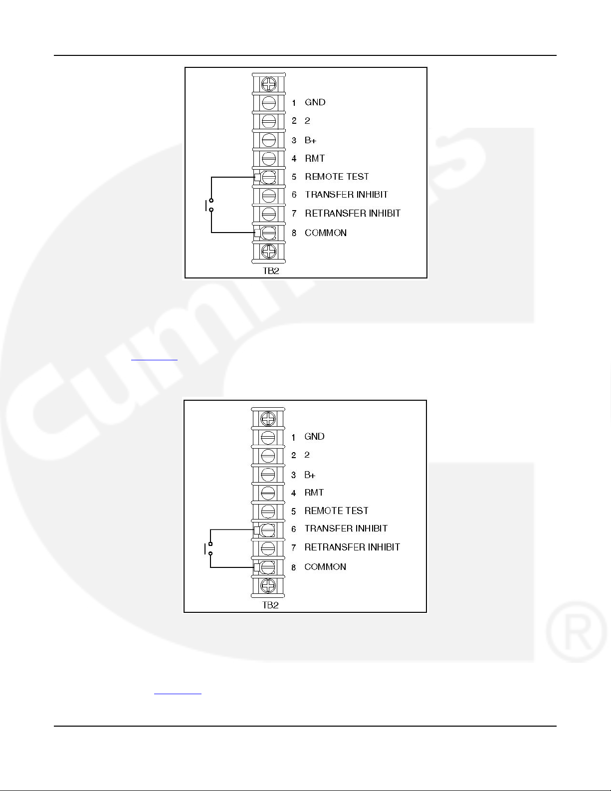
3.3.4 Remote Test Input
To add remote test, connect a normally open, dry contact between terminals 5 and 8 of TB2
(see Figure 17). Closing the contact activates the feature and opening the contact deactivates
it.
Use number 22 to number 12 AWG wire. For connection to the screw terminal, strip the
insulation back 3/8 inch (10 mm).
962-0617 (Issue 5) 27
Page 34
3. Wiring 4-2010
FIGURE 17. TB2 CONNECTIONS FOR REMOTE TEST TRANSFER
3.3.5 Transfer Inhibit Input
To add transfer inhibit, connect a normally open, dry contact between terminals 6 and 8 of TB2
(see Figure 18). Closing the contact enables the feature and opening the contact disables it.
Use number 22 to number 12 AWG wire. For connection to the screw terminal, strip the
insulation back 3/8 inch (10 mm).
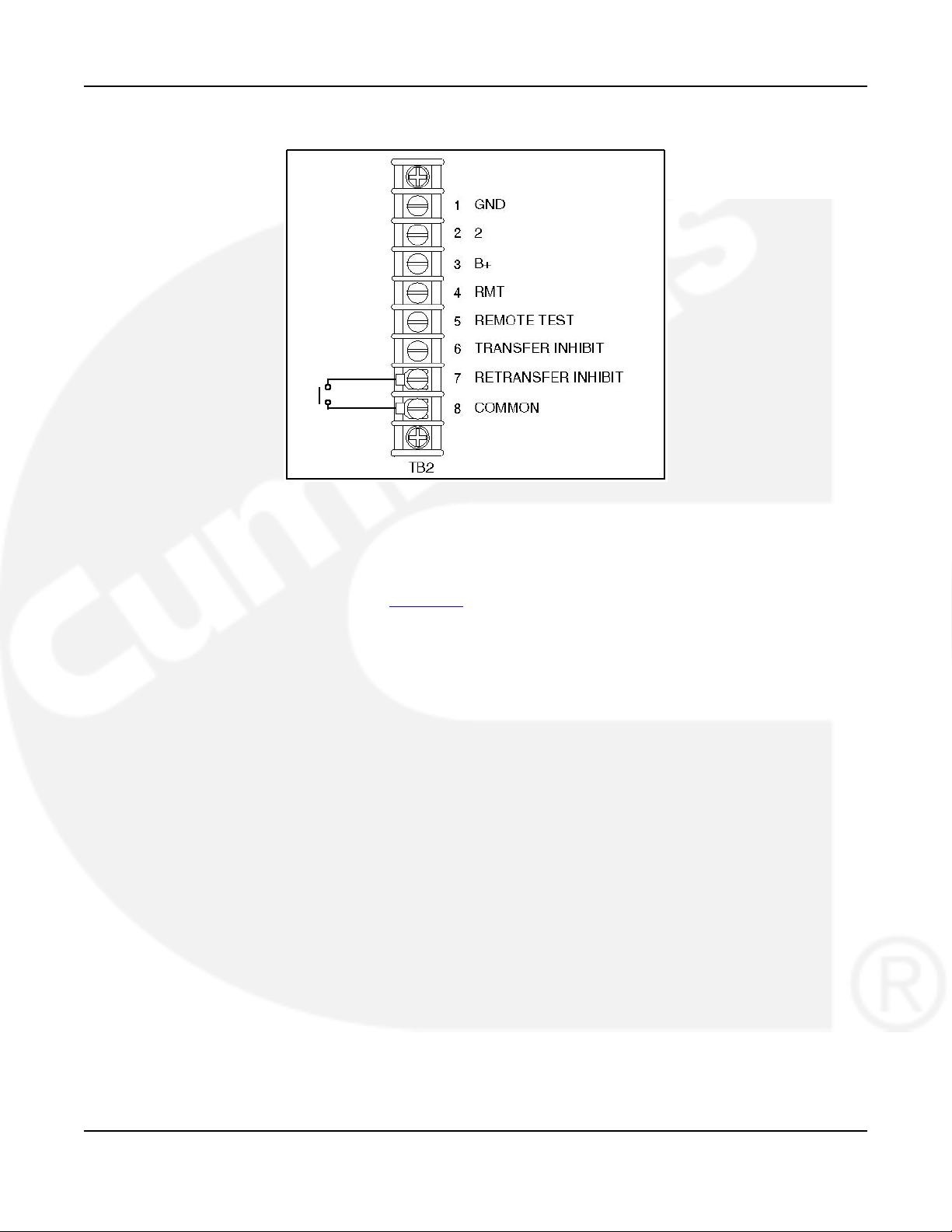
FIGURE 18.
3.3.6 Retransfer Inhibit Input
To add retransfer inhibit, connect a normally open, dry contact between terminals 7 and 8 of
TB2 (see Figure 19). Closing the contact enables the feature and opening the contact disables
it.
28 962-0617 (Issue 5)
Page 35
4-2010 3. Wiring
Use number 22 to number 12 AWG wire. For connection to the screw terminal, strip the
insulation back 3/8 inch (10 mm).
FIGURE 19. TB2 CONNECTIONS FOR RETRANSFER INHIBIT
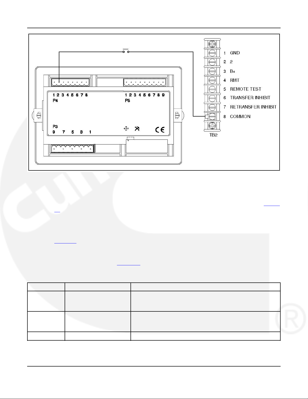
3.3.7 Remote Override Input
To add remote override, connect a normally open, dry contact between P4-2 on the back of the
control panel and TB2-8 (see Figure 20). Closing the contact enables the feature and opening
the contact disables it.
Use number 22 to number 12 AWG wire. For connection to the screw terminal, strip the
insulation back 3/8 inch (10 mm).
962-0617 (Issue 5) 29
Page 36
3. Wiring 4-2010
FIGURE 20. CONNECTIONS FOR REMOTE OVERRIDE INPUT
3.3.8 Auxiliary Relays and Elevator Relay Options
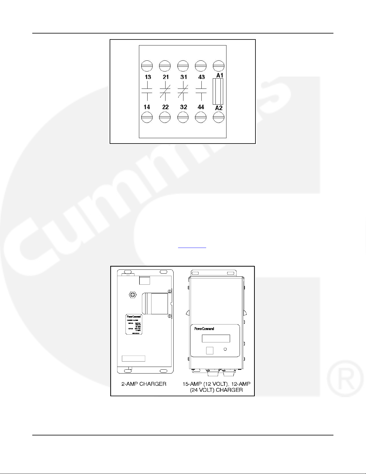
Connections to the auxiliary and elevator relays are made directly to the relay terminals. Figure
14 shows the location of the Auxiliary Relays on the options panel. The terminals accept wire
sizes from one number 18 AWG wire to two number 12 AWG wires. For connection to the screw
terminal, strip the insulation back 3/8 inch (10 mm).
There are two types of auxiliary relay coils (12 VDC and 24 VDC).
Table 12 lists the available auxiliary relay and elevator signal relay options, along with their
feature codes.
All relays have two normally open and two normally closed contacts that are rated for 6
amperes at 600 VAC (see Figure 21).
TABLE 12. AUXILIARY AND ELEVATOR RELAYS
Code Coil type Description
L101 24 Vdc Coil Installed, Not Wired
L102 24 Vdc Coil Emergency position Relay
L103 24 Vdc Coil Normal position Relay
L201 12 Vdc Coil Installed, Not Wired
L202 12 Vdc Coil Emergency position Relay
L203 12 Vdc Coil Normal position Relay
M032 12 or 24 vdc coil Elevator Signal Relay
30 962-0617 (Issue 5)
Page 37
4-2010 3. Wiring
FIGURE 21. RELAY TERMINALS
3.3.9 Battery Charger Options
When so equipped, a battery charger can be used for charging genset starting and control
batteries. These chargers are current limiting and supply automatic constant voltages.
When the battery approaches the full charge preset voltage, the charging current automatically
tapers to zero amperes or to a steady-state load on the battery.
A float-charge battery charger regulates its charge voltage to continuously charge without
damage to the battery. As the battery approaches full charge, the charging current automatically
tapers to zero amperes or to steady-state load on the battery.
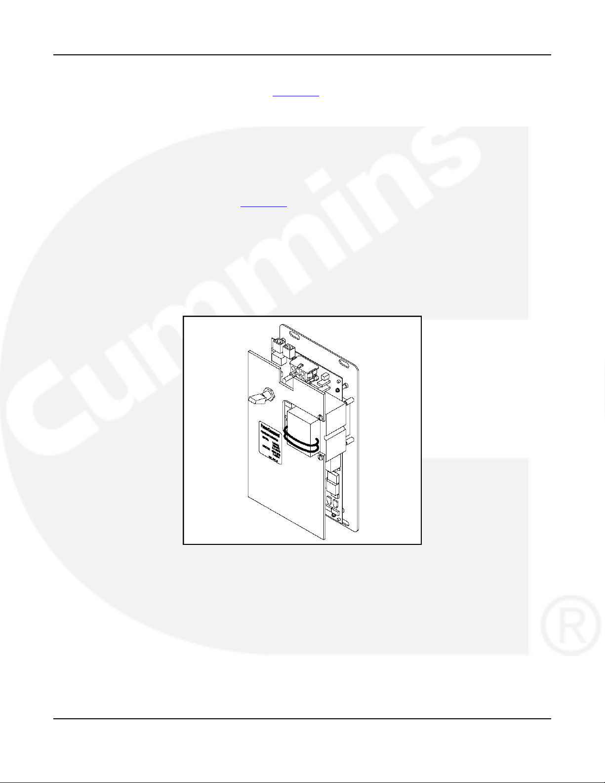
Two battery chargers are available (see Figure 22). One battery charger is rated for 2 amperes
at 12 or 24 VDC. The other battery charger is rated for 15 amperes at 12 VDC or 12 amperes at
24 VDC.
FIGURE 22. CURRENT BATTERY CHARGERS
962-0617 (Issue 5) 31
Page 38
3. Wiring 4-2010
3.3.9.1 2-Amp Battery Charger
The 2-ampere battery charger {see Figure 23) has a 5 amp DC output circuit breaker switch on
the front of the battery charger. The charger also includes a 5 amp AC fuse to protect the
battery charger circuit.
Under normal operating conditions, the Low Bat and AC Fail relays are energized and the High
Bat relay is de-energized. In response to a Low Bat or AC Fail condition, the appropriate
normally energized relay (Low Bat or AC Fail) drops out. In response to a High Bat condition,
the normally de-energized High Bat relay is energized.
Control Panel - The 2-amp charger control panel includes a digital display, a RESET button, and
an LED status indicator (see Figure 24).
· The 2-line X 16-character digital display displays menus and faults.
· The RESET button is used to select menu options and to clear fault messages.
· The status LED displays the appropriate color for the following conditions.
· Green - On solid indicates unit is charging
· Red - On solid indicates a fault condition. The fault number is sown on the digital
display.
FIGURE 23. 2-AMP POWERCOMMAND BATTERY CHARGER
32 962-0617 (Issue 5)
Page 39

4-2010 3. Wiring
FIGURE 24. 2-AMP CHARGER CONTROL PANEL
Battery Charger Configuration - The RESET button on the control panel (see Figure 24 is used
to configure the battery charger for the correct battery voltage. (More information on Setup
menus is included in the Battery Charger Operator's Manual.)
3.3.9.2 15/12-Amp Battery Charger
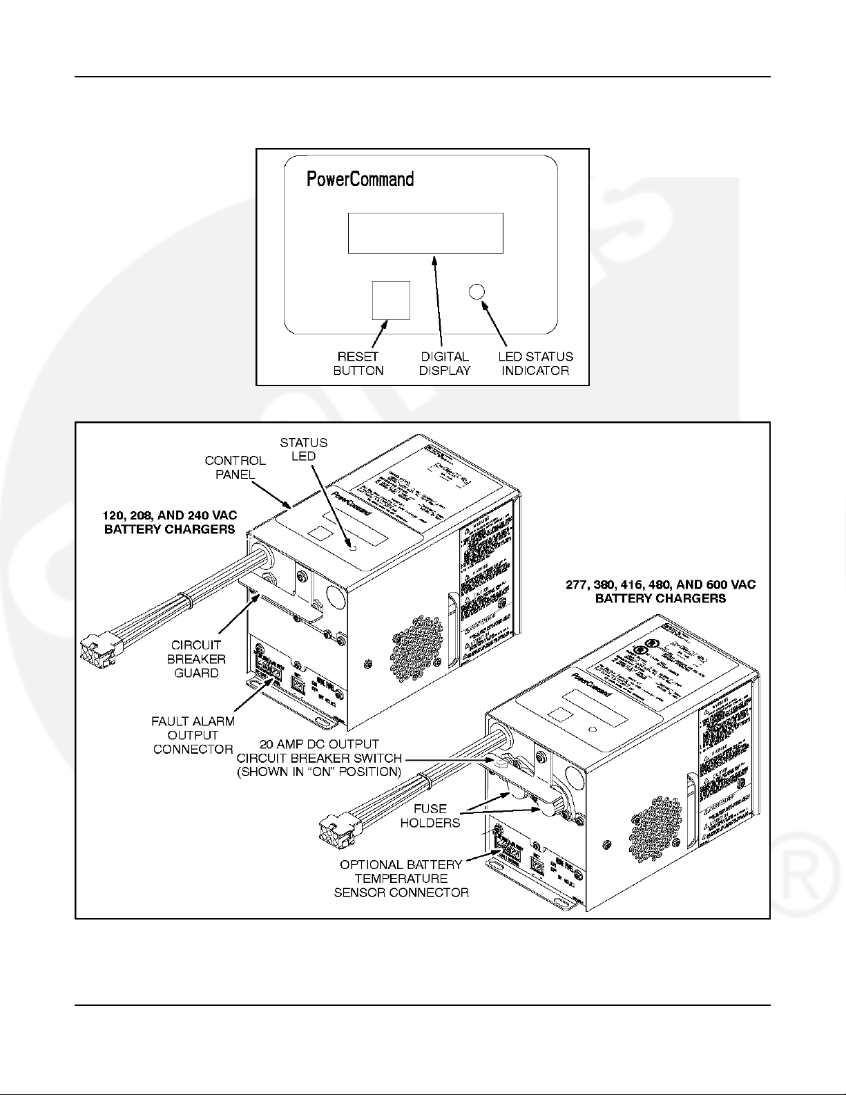
There are two types of 15/12-amp PowerCommand battery chargers (see Figure 26). All
I5/12-amp battery chargers have a 20 amp DC circuit breaker switch on the front of the battery
charger. The 120, 208, and 240 VAC battery chargers include two 10 amp AC circuit breaker
switches and a circuit breaker guard, while the 277, 380, 416, and 600 VAC battery chargers
include two AC fuse holders.
Control Panel - The 15/12-amp charger control panel includes a digital display, a Reset button,
and an LED status indicator (see Figure 25).
· The 2-line x 16-character digital display displays menus and faults.
· The Reset button is used to select menu options and to clear fault messages.
· The status LED is displays the appropriate color for the following conditions.
· Green - On solid indicates unit is charging
· Amber - On solid indicates Equalizing
· Red - On solid indicates a fault condition. The fault number is shown on the digital
display.
Optional Battery Temperature Sensor - A connector for an optional battery temperature sensor
is located on the front of the battery charger. When used to monitor battery temperature, the
optional battery temperature sensor is connected from the battery charger to the positive
terminal of the battery. A fault message (fault code 2263) is displayed if the battery temperature
is too high (reaches 131 degrees F (55 degrees C)).
Battery Charger Configuration - The RESET button on the control panel (see Figure 25) is used
to configure the battery charger, (More information on Setup menus is included in the Battery
Charger Operator's Manual .)
· Battery Voltage and Type - The battery charger must be correctly configured, using the
Setup menus, for the correct battery voltage and type before it is connected to the battery.
The battery voltage can be set for 12 or 24 VDC (default = 12 VDC). The battery type can
be set for Lead-Acid, Gel, or AGM batteries (default = Lead-Acid) .
NOTE: A factory installed battery charger is set up for the proper DC battery voltage
requested on the production order, with the Lead-Acid battery type selected
as the default.
962-0617 (Issue 5) 33
Page 40
3. Wiring 4-2010
· Battery Equalization - Battery equalization is available for lead-acid batteries that are
completely charged, using the Equalize Battery screen in the Setup menus. When
batteryequalization is in process, the LED status indicator turns amber.
FIGURE 25. 15/12-AMP CHARGER CONTROL PANEL
FIGURE 26. 15/12-AMP POWERCOMMAND BATTERY CHARGERS
34 962-0617 (Issue 5)
Page 41
4-2010 3. Wiring
3.3.10 Battery Charger Alarm Contacts Option
The optional 10-ampere battery charger can include three sets of Form-C relay contacts, as an
additional option.
Under normal operating conditions, the Low Bat and AC Fail relays are energized and the High
Bat relay is de-energized. In response to a Low Bat or AC Fail condition, the appropriate
normally energized relay (Low Bat or AC Fail) drops out. In response to a High Bat condition,
the normally de-energized High Bat relay is energized.
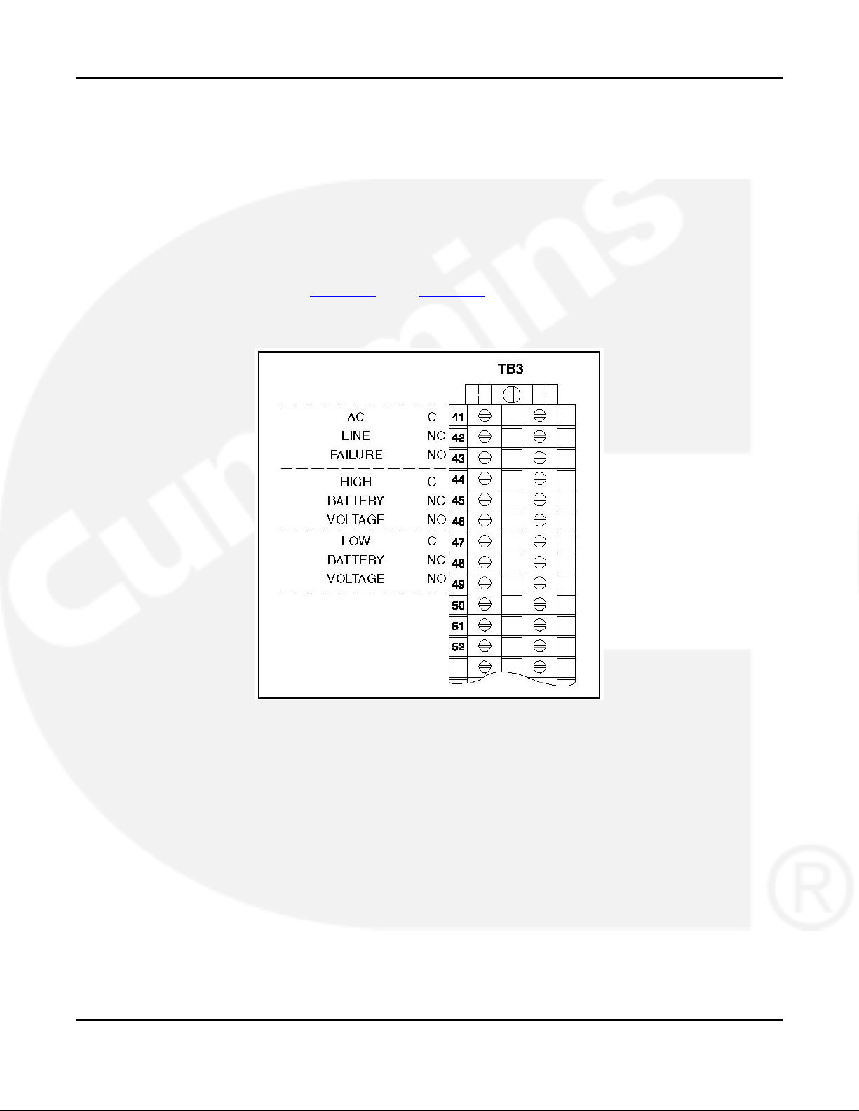
The contacts are rated for 4 amperes at 120 VAC or 30 VDC. Connections to these contacts are
made at terminals 41-42-43 (AC failure), 44-45-46 (high battery voltage), and 47-48-49 (low
battery voltage) of TB3 (Figure 27). See Figure 14 for the location of TB3 on the option panel.
Use number 22 to number 12 AWG wire. For connection to the screw terminal, strip the
insulation back 3/8 inch (10 mm).
FIGURE 27. BATTERY CHARGER ALARM CONTACTS
3.4 Inspection and Cleanup
· Inspect all wiring to be certain that:
· Wiring does not interfere with switch operation
· Wiring is not damaged as the door opens and closes
· Wiring does not contact sharp or abrasive surfaces
· No wiring is left loose and unconnected
· After mounting and wiring the cabinet, clean the interior with a vacuum cleaner to remove
any chips, filings, or dirt from the cabinet interior and components.
· Double check the power supply voltages to make sure they match the voltages listed on
the nameplate.
962-0617 (Issue 5) 35
Page 42

3. Wiring 4-2010
· Double check the phase rotation. The Normal side phase rotation must match the
Emergency side phase rotation.
· Verify that the remote start connections are correct for your application. For more
information on jumper replacement, determine the control type and refer to information
provided earlier in this section.
· Manually operate the ATS with power off to make sure it operates smoothly, with no
binding. If it does not operate smoothly, check for damage that may have occurred during
shipping or installation. Also check for installation debris.
36 962-0617 (Issue 5)
Page 43

Appendix A. Interconnect Diagrams and
Outline Drawings
Table of Contents
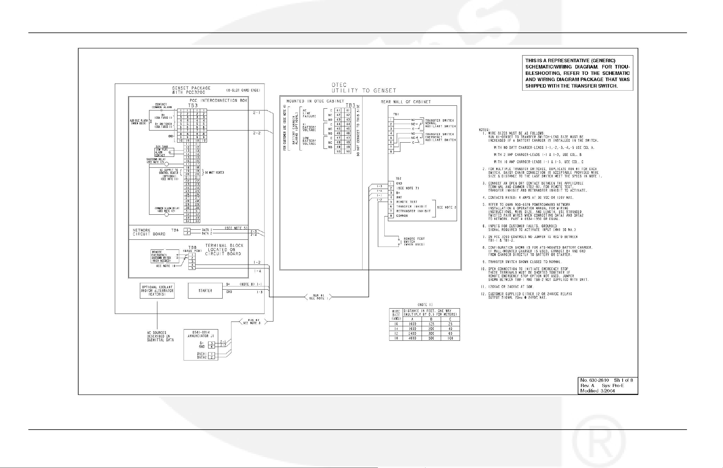
Figure 28. 40-1200 Amp Typical Interconnection Diagram 630-2810 (Sheet 1 of 8) .............................. 39
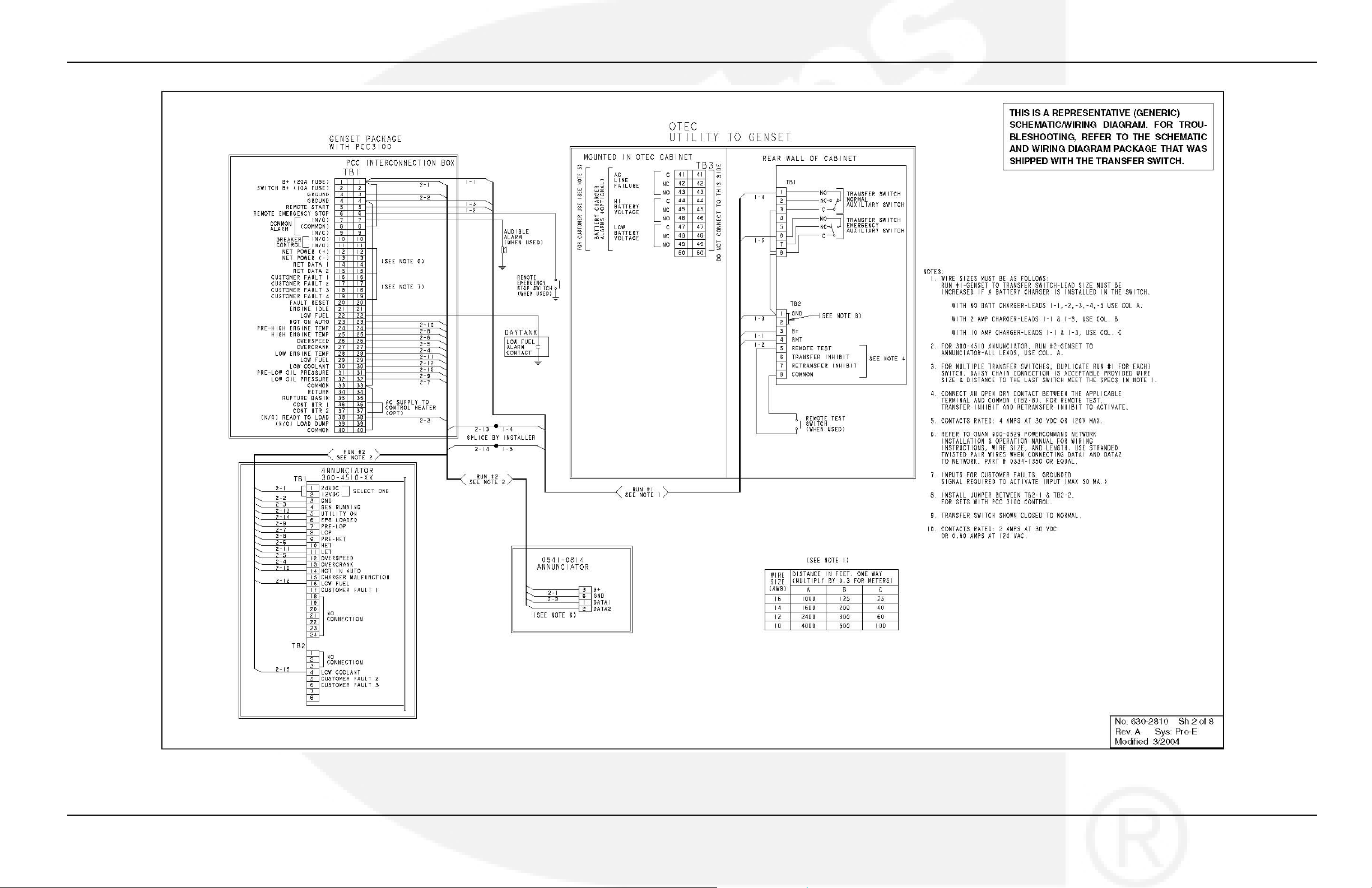
Figure 29. 40-1200 Amp Typical Interconnection Diagram 630-2810 (Sheet 2 of 8) .............................. 40
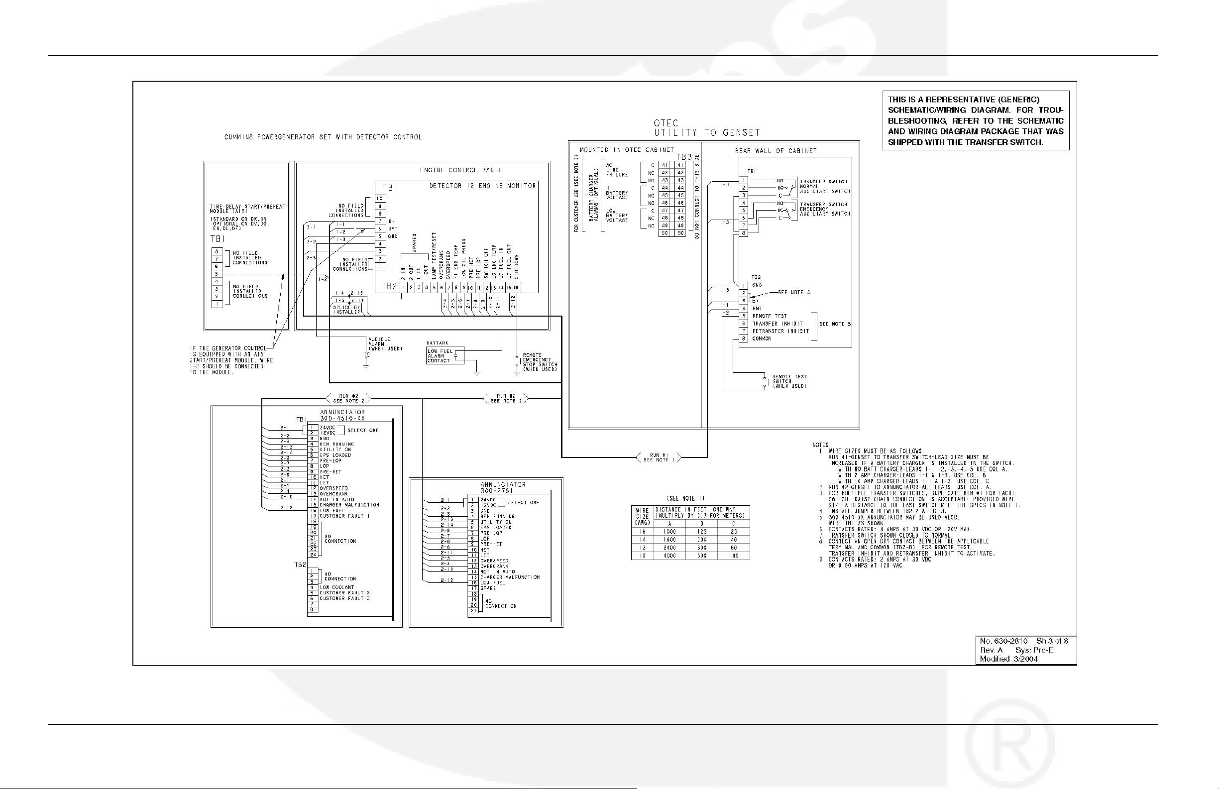
Figure 30. 40-1200 Amp Typical Interconnection Diagram 630-2810 (Sheet 3 of 8) .............................. 41
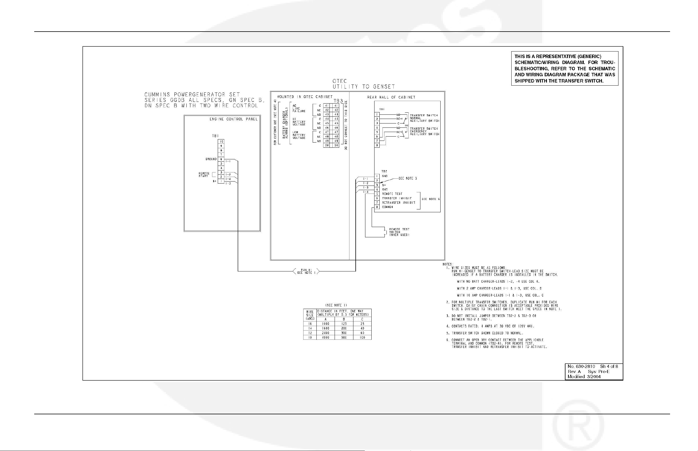
Figure 31. 40-1200 Amp Typical Interconnection Diagram 630-2810 (Sheet 4 of 8) .............................. 42
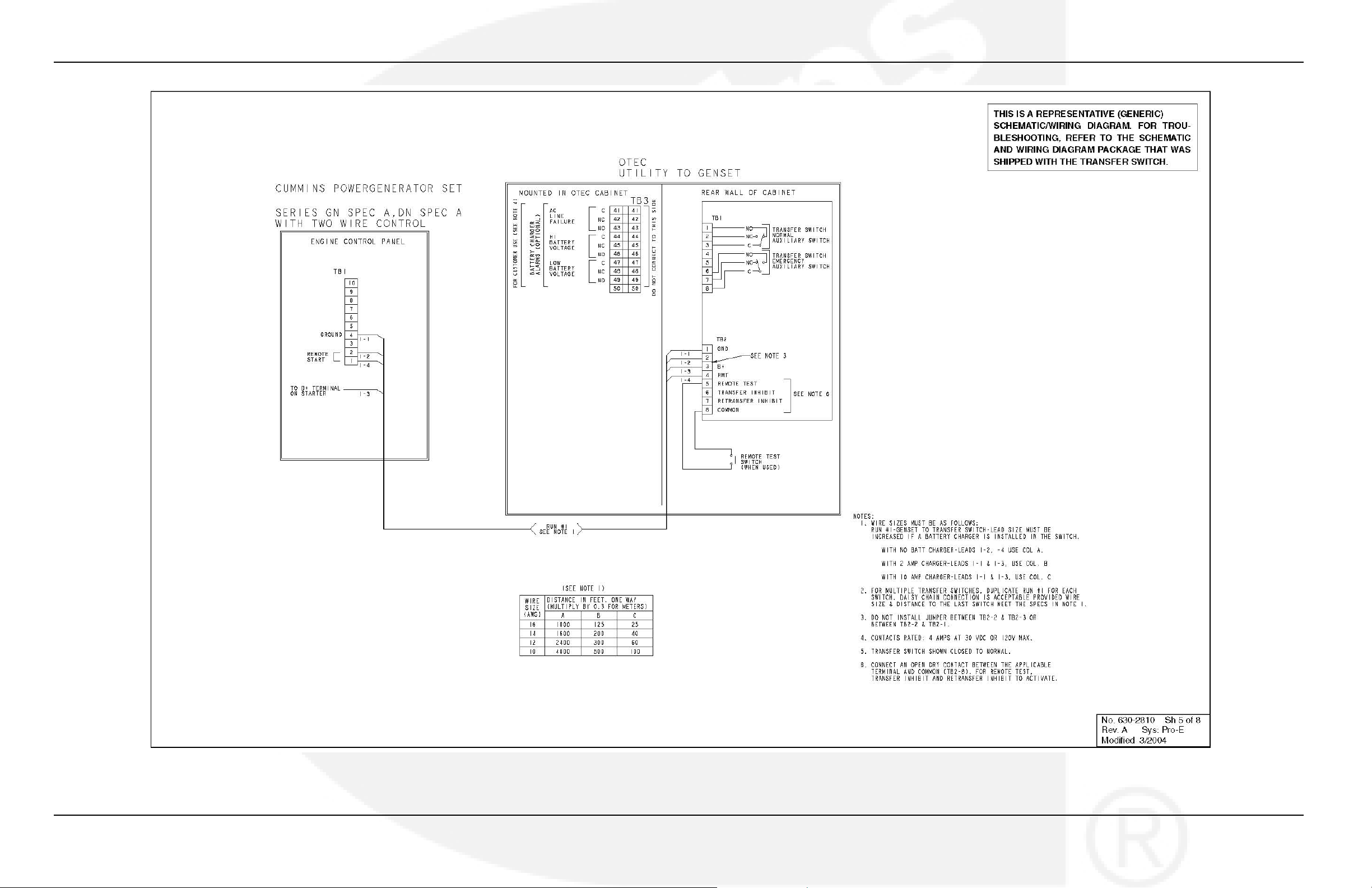
Figure 32. 40-1200 Amp Typical Interconnection Diagram 630-2810 (Sheet 5 of 8) .............................. 43
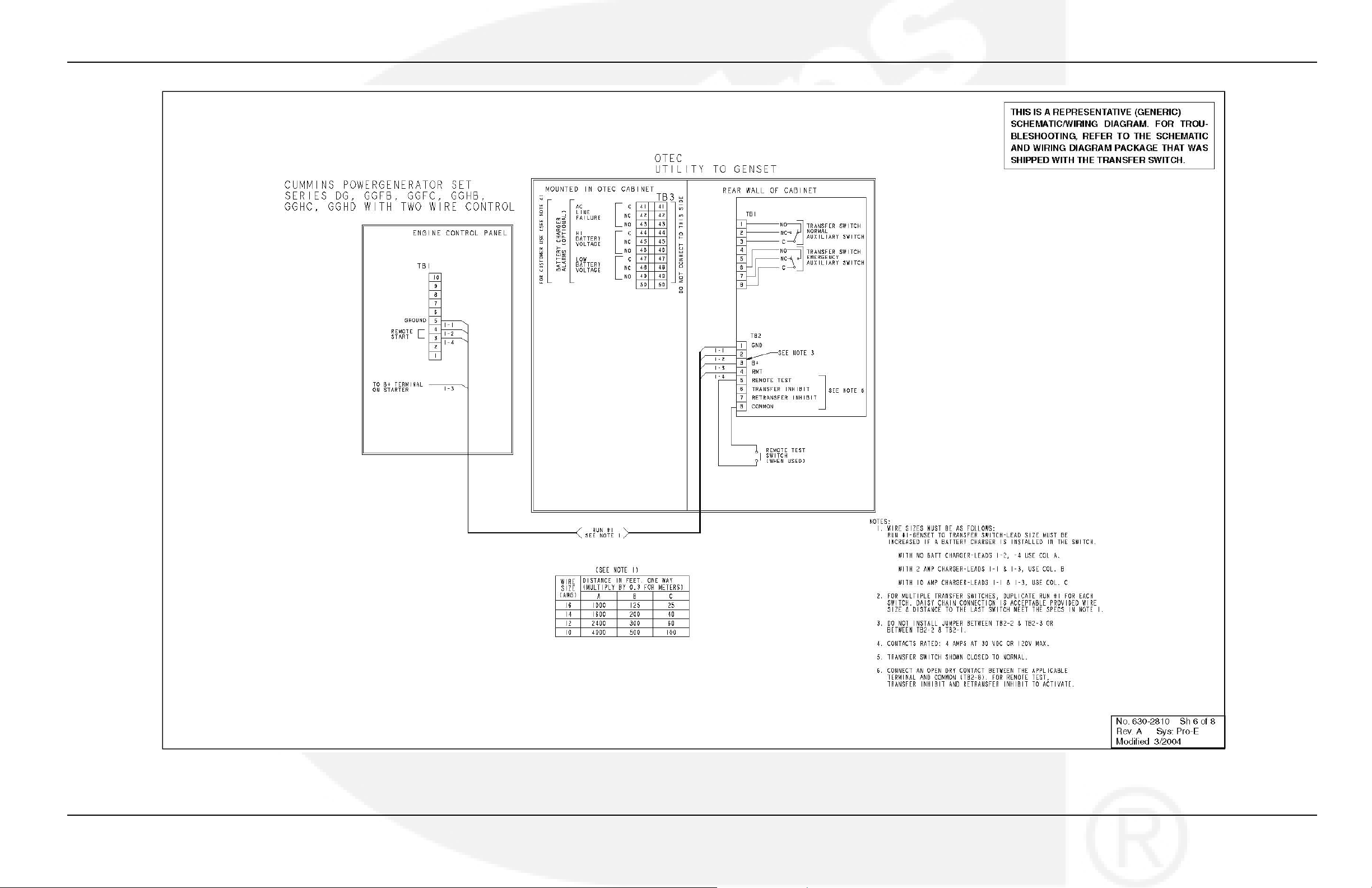
Figure 33. 40-1200 Amp Typical Interconnection Diagram 630-2810 (Sheet 6 of 8) .............................. 44
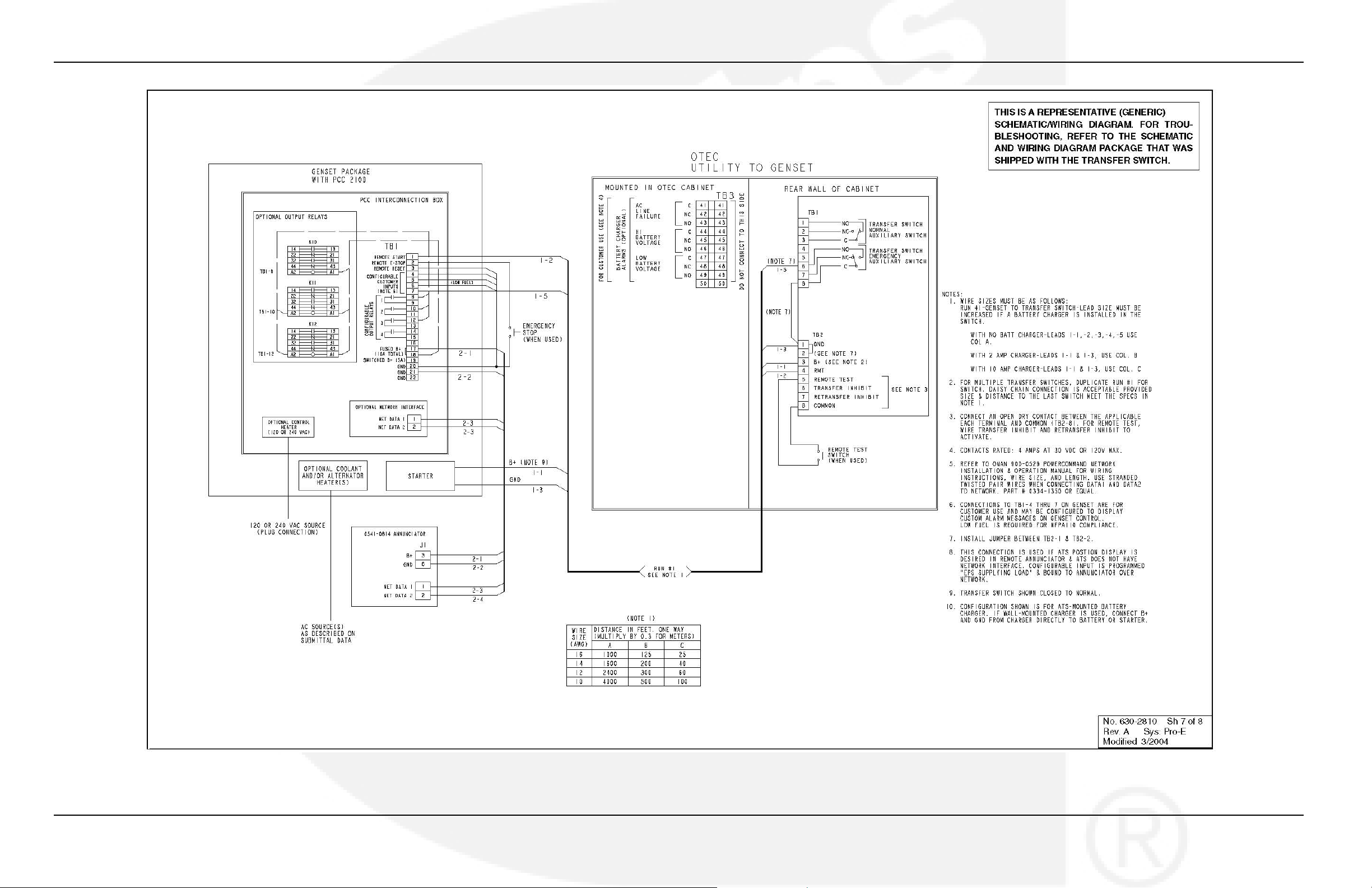
Figure 34. 40-1200 Amp Typical Interconnection Diagram 630-2810 (Sheet 7 of 8) .............................. 45
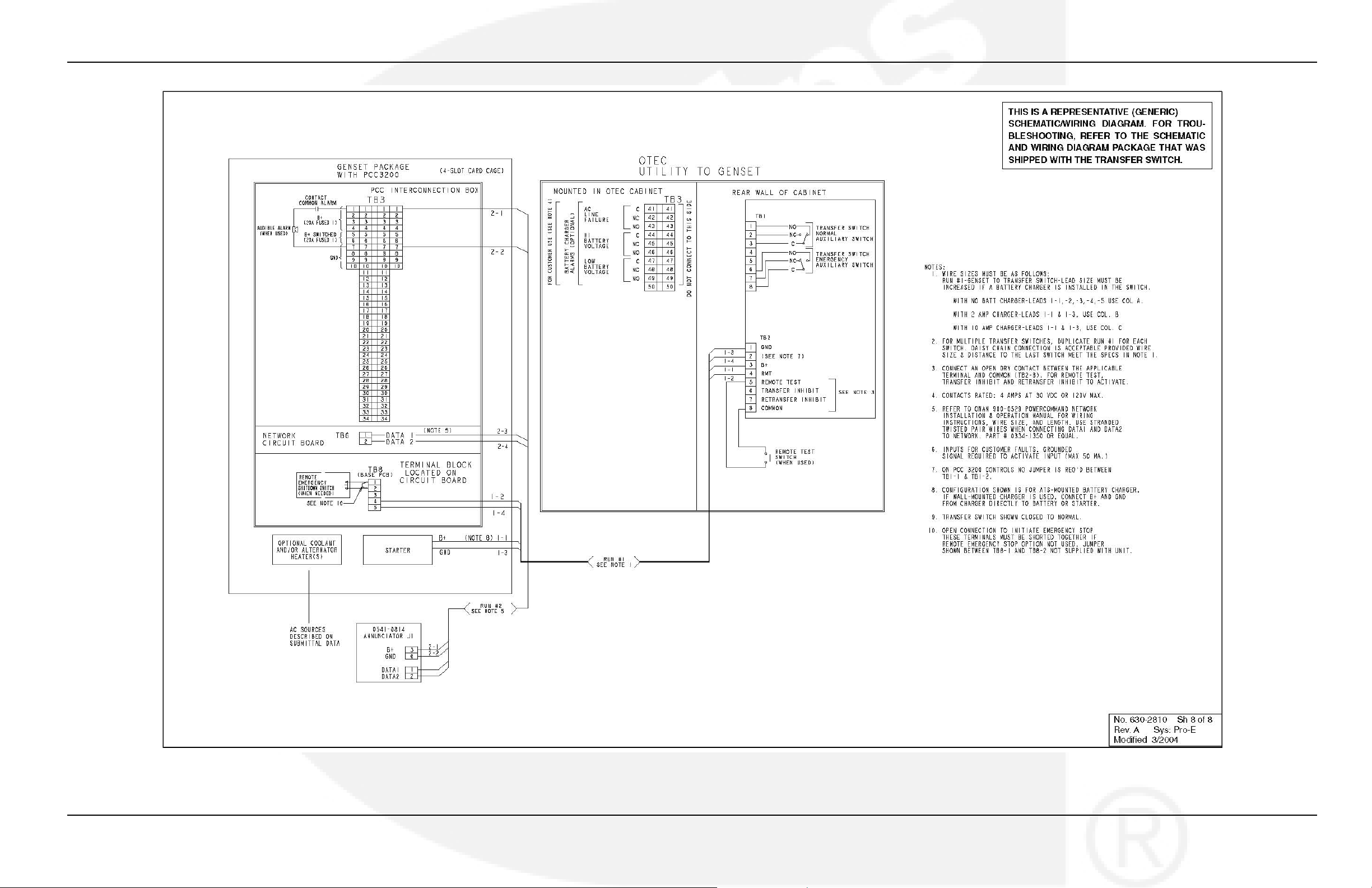
Figure 35. 40-1200 Amp Typical Interconnection Diagram 630-2810 (Sheet 8 of 8) .............................. 46
Figure 36. NEMA 1 Control Box Outline Drawing 310-0544, 40-125 Amp .............................................. 47
Figure 37. NEMA 1 Control Box Outline Drawing 310-0414, 150-225 Amp (Sheet 1 of 2) ..................... 48
Figure 38. NEMA 1 Control Box Outline Drawing 310-0414, 150-225 Amp (Sheet 2 of 2) ..................... 49
Figure 39. NEMA 1 Control Box Outline Drawing 310-0540, 260 Amp (Sheet 1 of 2) ............................ 50
Figure 40. NEMA 1 Control Box Outline Drawing 310-0540, 260 Amp (Sheet 2 of 2) ............................ 51
Figure 41. NEMA 1 Control Box Outline Drawing 310-1307, 300-600 Amp ............................................ 52
Figure 42. NEMA 1 Control Box Outline Drawing 310-0417, 800 and 1000 Amp (Sheet 1 of 2) ........... 53
Figure 43. NEMA 1 Control Box Outline Drawing 310-0417, 800 and 1000 Amp (Sheet 2 of 2) ........... 54
Figure 44. NEMA 3R and 12 Control Box Outline Drawing 310-0453, 40-125 Amp ............................... 55
Figure 45. NEMA 3R and 12 Control Box Outline Drawing 310-0454, 150-225 Amp (Sheet 1 of 2) ..... 56
Figure 46. NEMA 3R and 12 Control Box Outline Drawing 310-0454, 150-225 Amp (Sheet 2 of 2) ..... 57
Figure 47. NEMA 3R and 12 Control Box Outline Drawing 310-0455, 260 Amp (Sheet 1 of 2) ............. 58
Figure 48. NEMA 3R and 12 Control Box Outline Drawing 310-0455, 260 Amp (Sheet 2 of 2) ............. 59
Figure 49. NEMA 3R and 12 Control Box Outline Drawing 310-1315, 300-600 Amp ............................. 60
Figure 50. NEMA 3R and 12 Control Box Outline Drawing 310-0457, 800 and 1000 Amp (Sheet 1 of
2) .................................................................................................................................................................... 61
Figure 51. NEMA 3R and 12 Control Box Outline Drawing 310-0457, 800 and 1000 Amp (Sheet 2 of
2) .................................................................................................................................................................... 62
Figure 52. NEMA 4 Control Box Outline Drawing 310-0445, 40-125 Amp .............................................. 63
Figure 53. NEMA 4 Control Box Outline Drawing 310-0446, 150-225 Amp (Sheet 1 of 2) ..................... 64
Figure 54. NEMA 4 Control Box Outline Drawing 310-0446, 150-225 Amp (Sheet 2 of 2) ..................... 65
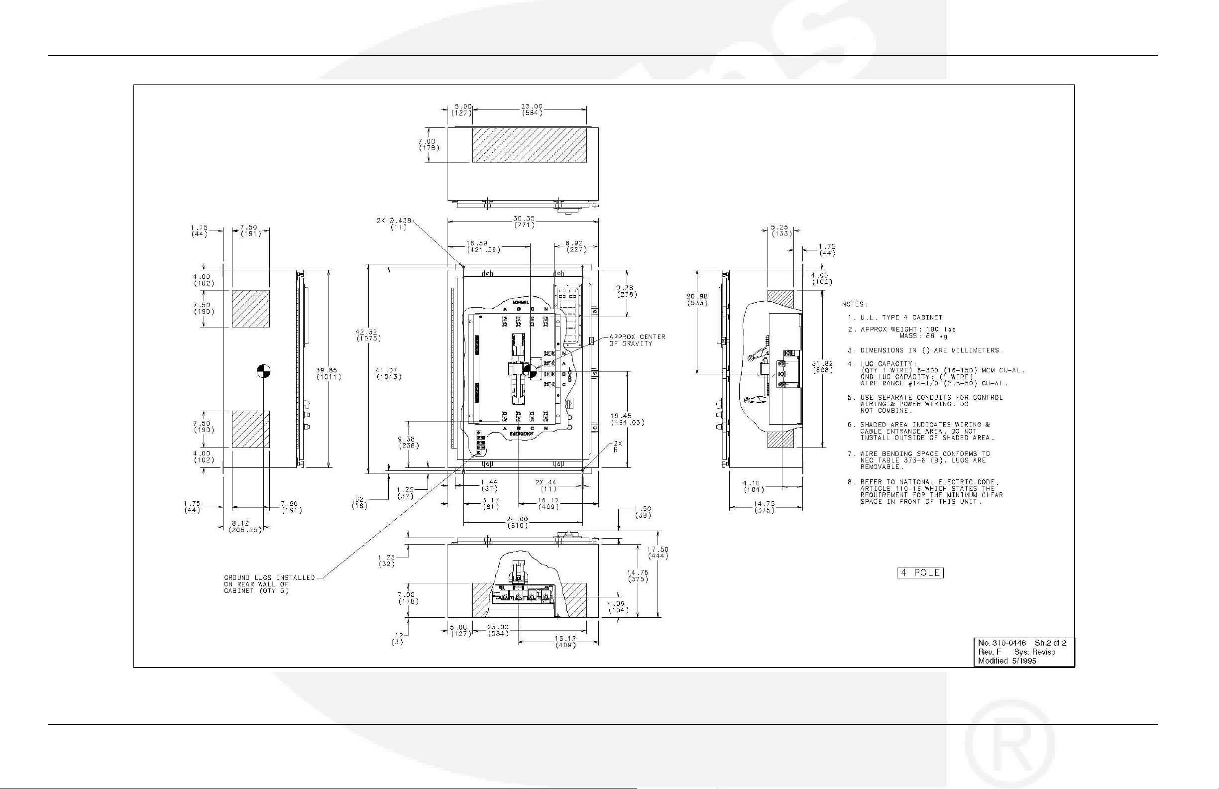
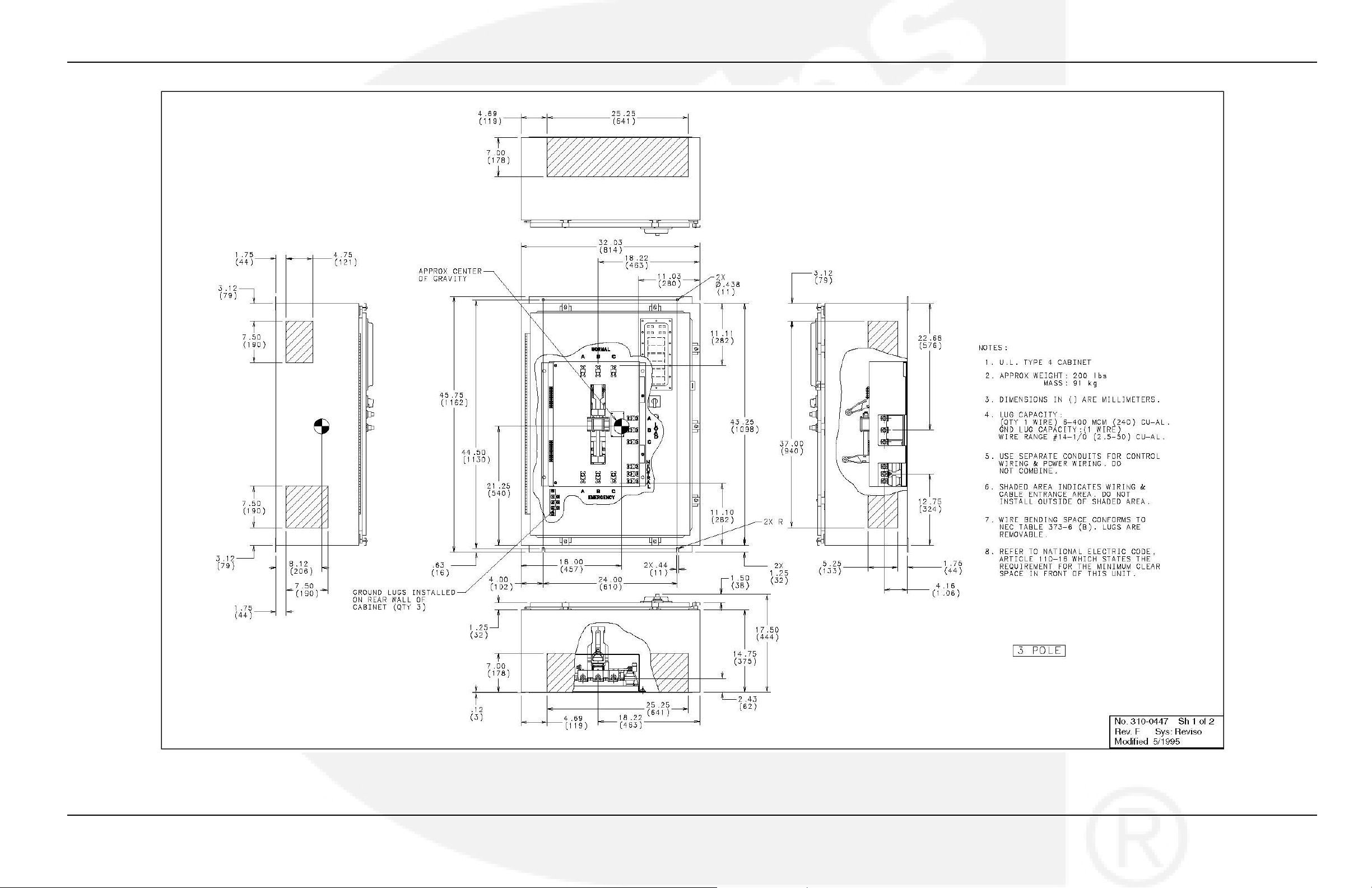
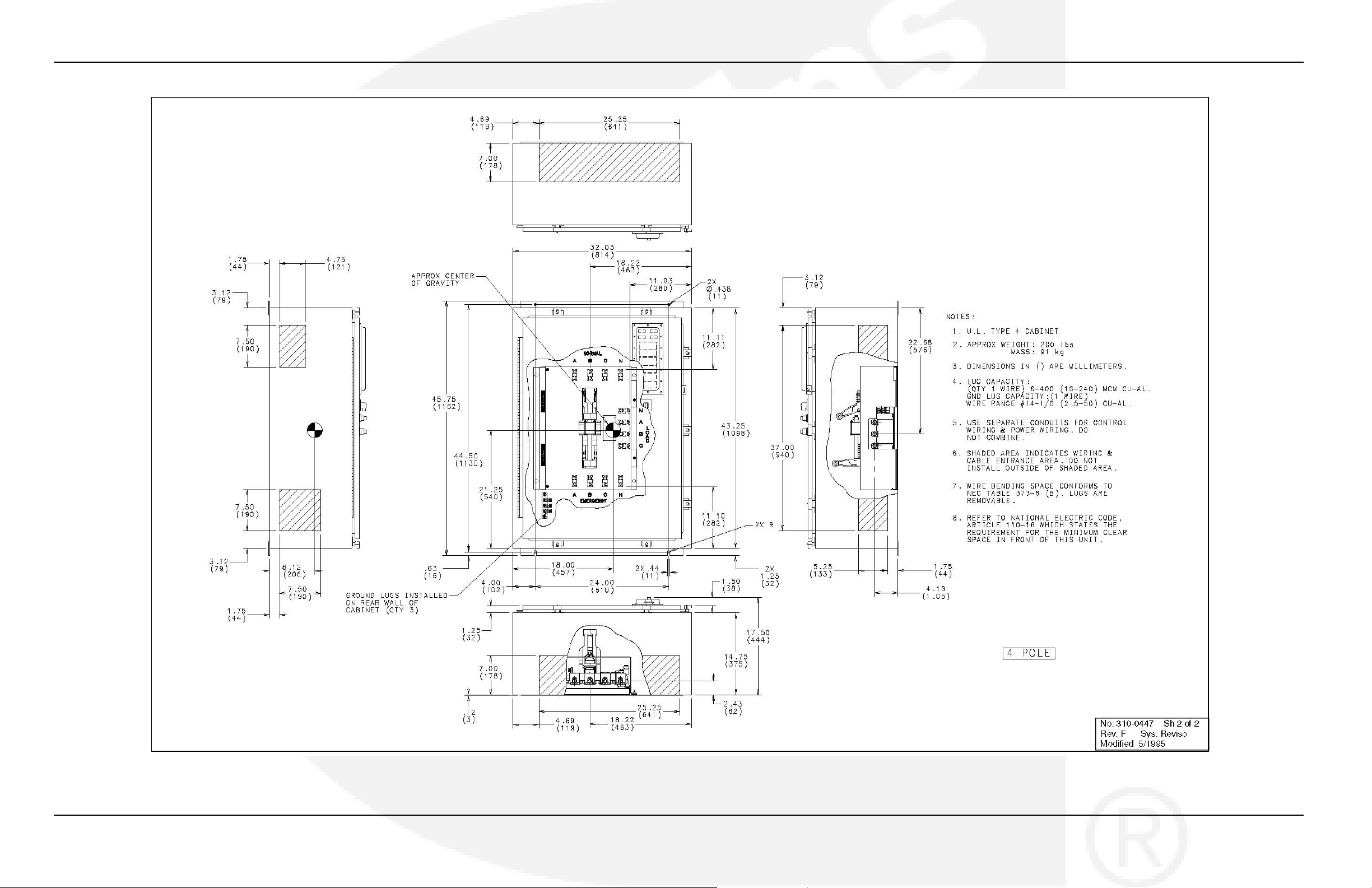
Figure 55. NEMA 4 Control Box Outline Drawing 310-0447, 260 Amp (Sheet 1 of 2) ............................ 66
Figure 56. NEMA 4 Control Box Outline Drawing 310-0447, 260 Amp (Sheet 2 of 2) ............................ 67
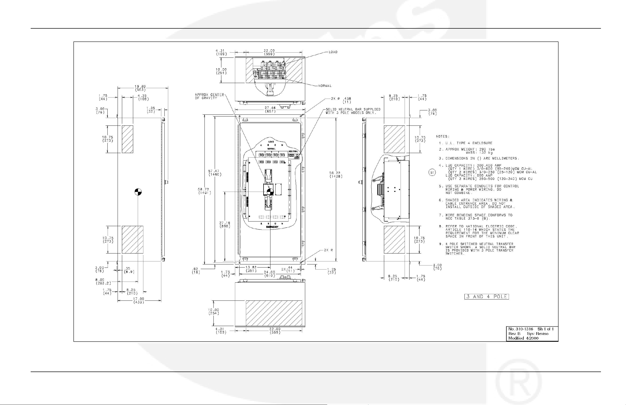
Figure 57. NEMA 4 Control Box Outline Drawing 310-1316, 300-600 Amp ............................................ 68
Figure 58. NEMA 4 Control Box Outline Drawing 310-0449, 800 and 1000 Amp (Sheet 1 of 2) ........... 69
962-0617 (Issue 5) 37
Page 44

Appendix A. Interconnect Diagrams and Outline Drawings 4-2010
Figure 59. NEMA 4 Control Box Outline Drawing 310-0449, 800 and 1000 Amp (Sheet 2 OF 2) .......... 70
Figure 60. NEMA 1, 3R, 4, and 12 Control Box Outline Drawing A030L411, 1200 Amp (Sheet 1 of 2) 71
Figure 61. NEMA 1, 3R, 4, and 12 Control Box Outline Drawing A030L411, 1200 Amp (Sheet 2 of 2) 72
38 962-0617 (Issue 5)
Page 45
4-2010 Appendix A. Interconnect Diagrams and Outline Drawings
FIGURE 28. 40-1200 AMP TYPICAL INTERCONNECTION DIAGRAM 630-2810 (SHEET 1 OF 8)
962-0617 (Issue 5) 39
Page 46
Appendix A. Interconnect Diagrams and Outline Drawings 4-2010
FIGURE 29. 40-1200 AMP TYPICAL INTERCONNECTION DIAGRAM 630-2810 (SHEET 2 OF 8)
40 962-0617 (Issue 5)
Page 47
4-2010 Appendix A. Interconnect Diagrams and Outline Drawings
FIGURE 30. 40-1200 AMP TYPICAL INTERCONNECTION DIAGRAM 630-2810 (SHEET 3 OF 8)
962-0617 (Issue 5) 41
Page 48
Appendix A. Interconnect Diagrams and Outline Drawings 4-2010
FIGURE 31. 40-1200 AMP TYPICAL INTERCONNECTION DIAGRAM 630-2810 (SHEET 4 OF 8)
42 962-0617 (Issue 5)
Page 49
4-2010 Appendix A. Interconnect Diagrams and Outline Drawings
FIGURE 32. 40-1200 AMP TYPICAL INTERCONNECTION DIAGRAM 630-2810 (SHEET 5 OF 8)
962-0617 (Issue 5) 43
Page 50
Appendix A. Interconnect Diagrams and Outline Drawings 4-2010
FIGURE 33. 40-1200 AMP TYPICAL INTERCONNECTION DIAGRAM 630-2810 (SHEET 6 OF 8)
44 962-0617 (Issue 5)
Page 51
4-2010 Appendix A. Interconnect Diagrams and Outline Drawings
FIGURE 34. 40-1200 AMP TYPICAL INTERCONNECTION DIAGRAM 630-2810 (SHEET 7 OF 8)
962-0617 (Issue 5) 45
Page 52
Appendix A. Interconnect Diagrams and Outline Drawings 4-2010
FIGURE 35. 40-1200 AMP TYPICAL INTERCONNECTION DIAGRAM 630-2810 (SHEET 8 OF 8)
46 962-0617 (Issue 5)
Page 53
4-2010 Appendix A. Interconnect Diagrams and Outline Drawings
FIGURE 36. NEMA 1 CONTROL BOX OUTLINE DRAWING 310-0544, 40-125 AMP
962-0617 (Issue 5) 47
Page 54
Appendix A. Interconnect Diagrams and Outline Drawings 4-2010
FIGURE 37. NEMA 1 CONTROL BOX OUTLINE DRAWING 310-0414, 150-225 AMP (SHEET 1 OF 2)
48 962-0617 (Issue 5)
Page 55
4-2010 Appendix A. Interconnect Diagrams and Outline Drawings
FIGURE 38. NEMA 1 CONTROL BOX OUTLINE DRAWING 310-0414, 150-225 AMP (SHEET 2 OF 2)
962-0617 (Issue 5) 49
Page 56
Appendix A. Interconnect Diagrams and Outline Drawings 4-2010
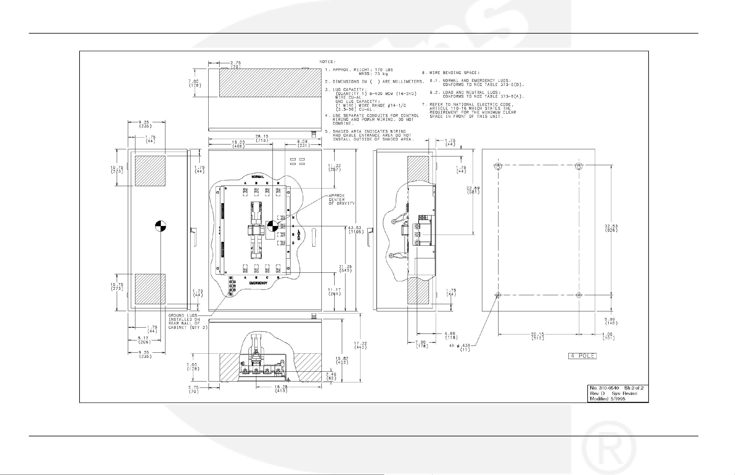
FIGURE 39. NEMA 1 CONTROL BOX OUTLINE DRAWING 310-0540, 260 AMP (SHEET 1 OF 2)
50 962-0617 (Issue 5)
Page 57
4-2010 Appendix A. Interconnect Diagrams and Outline Drawings
FIGURE 40. NEMA 1 CONTROL BOX OUTLINE DRAWING 310-0540, 260 AMP (SHEET 2 OF 2)
962-0617 (Issue 5) 51
Page 58

Appendix A. Interconnect Diagrams and Outline Drawings 4-2010
FIGURE 41. NEMA 1 CONTROL BOX OUTLINE DRAWING 310-1307, 300-600 AMP
52 962-0617 (Issue 5)
Page 59
4-2010 Appendix A. Interconnect Diagrams and Outline Drawings
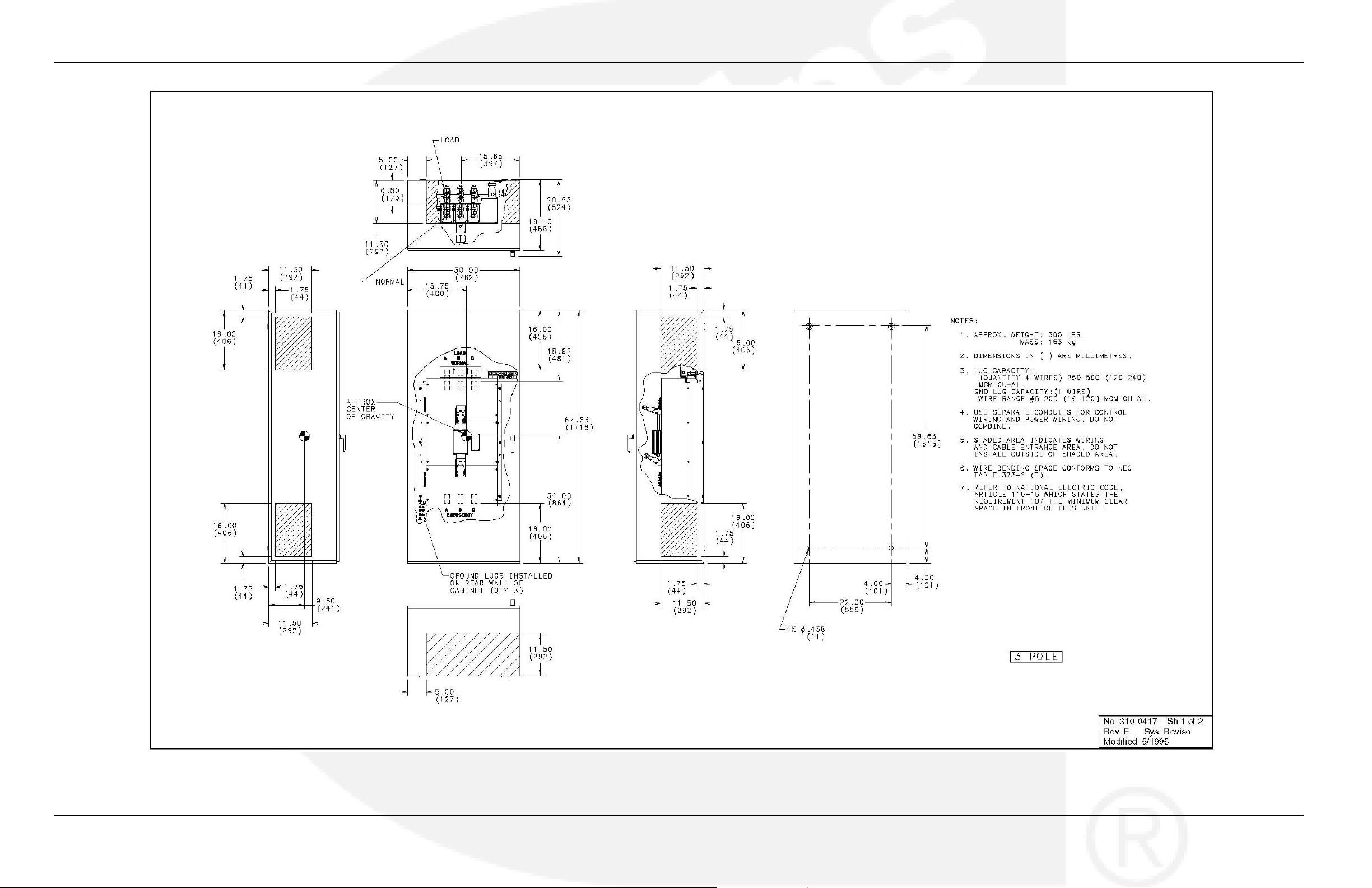
FIGURE 42. NEMA 1 CONTROL BOX OUTLINE DRAWING 310-0417, 800 AND 1000 AMP (SHEET 1 OF 2)
962-0617 (Issue 5) 53
Page 60
Appendix A. Interconnect Diagrams and Outline Drawings 4-2010
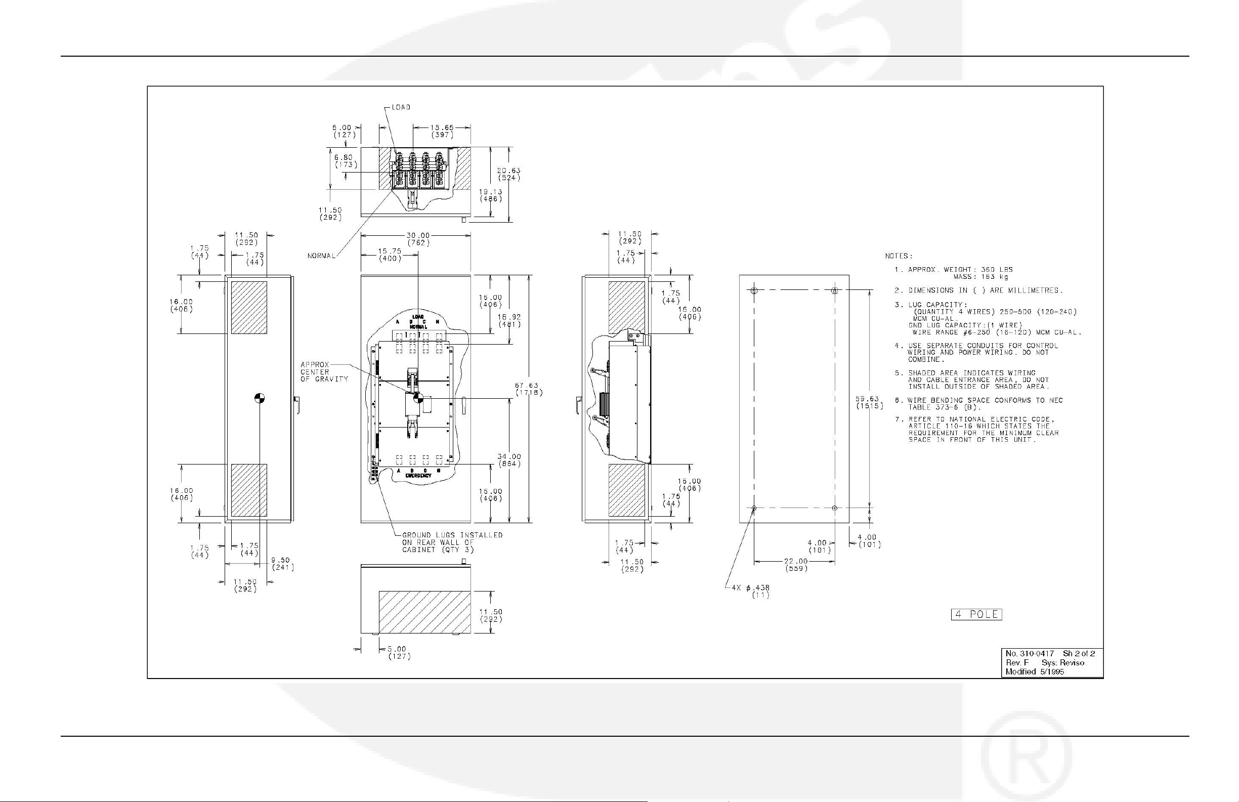
FIGURE 43. NEMA 1 CONTROL BOX OUTLINE DRAWING 310-0417, 800 AND 1000 AMP (SHEET 2 OF 2)
54 962-0617 (Issue 5)
Page 61
4-2010 Appendix A. Interconnect Diagrams and Outline Drawings
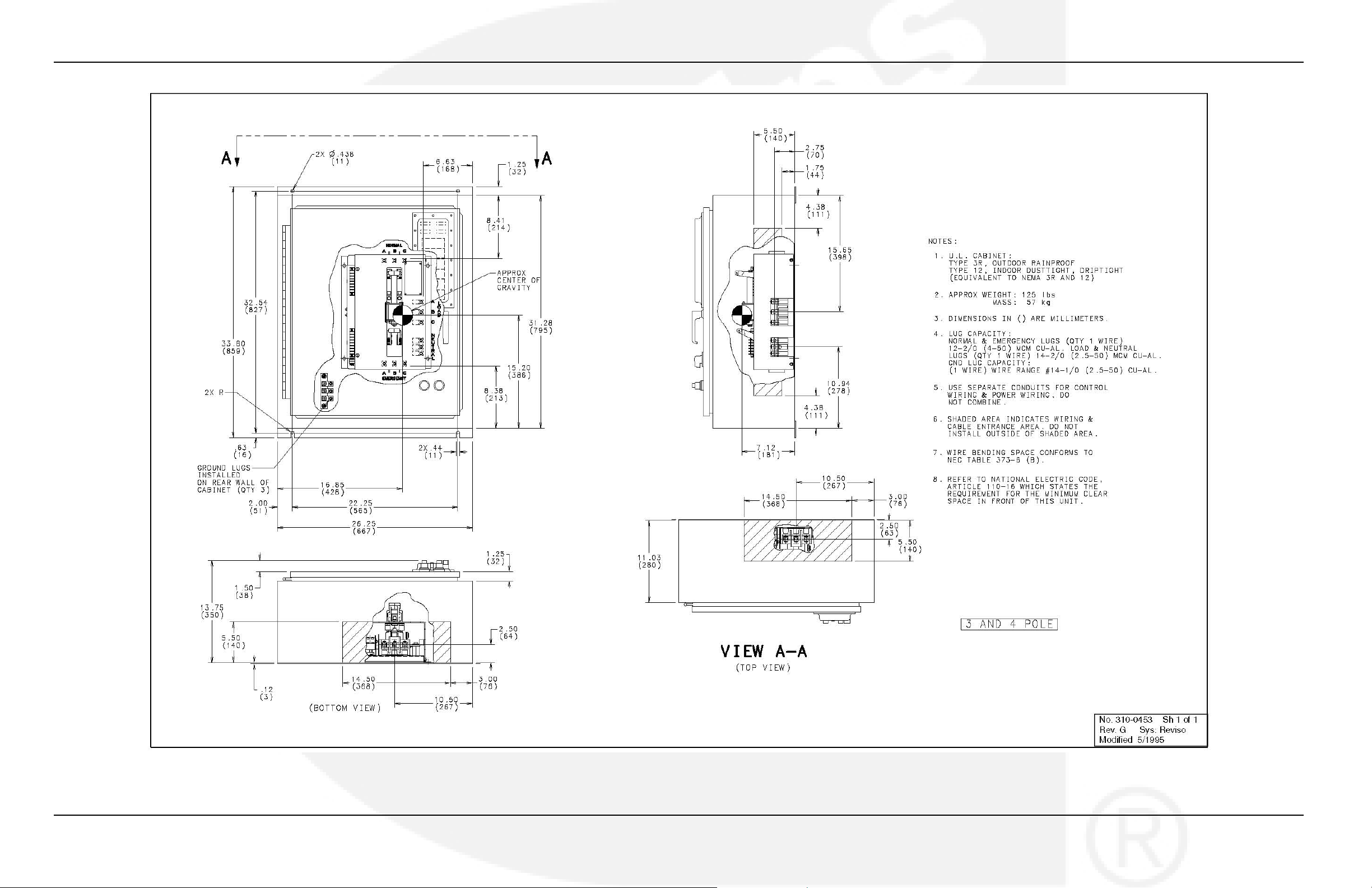
FIGURE 44. NEMA 3R AND 12 CONTROL BOX OUTLINE DRAWING 310-0453, 40-125 AMP
962-0617 (Issue 5) 55
Page 62
Appendix A. Interconnect Diagrams and Outline Drawings 4-2010
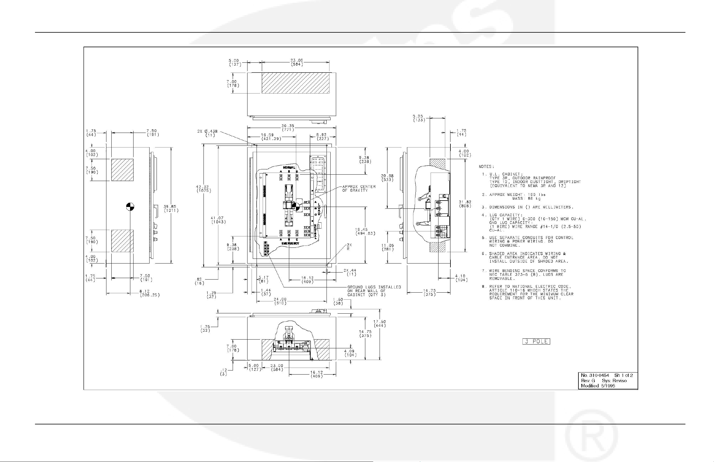
FIGURE 45. NEMA 3R AND 12 CONTROL BOX OUTLINE DRAWING 310-0454, 150-225 AMP (SHEET 1 OF 2)
56 962-0617 (Issue 5)
Page 63
4-2010 Appendix A. Interconnect Diagrams and Outline Drawings
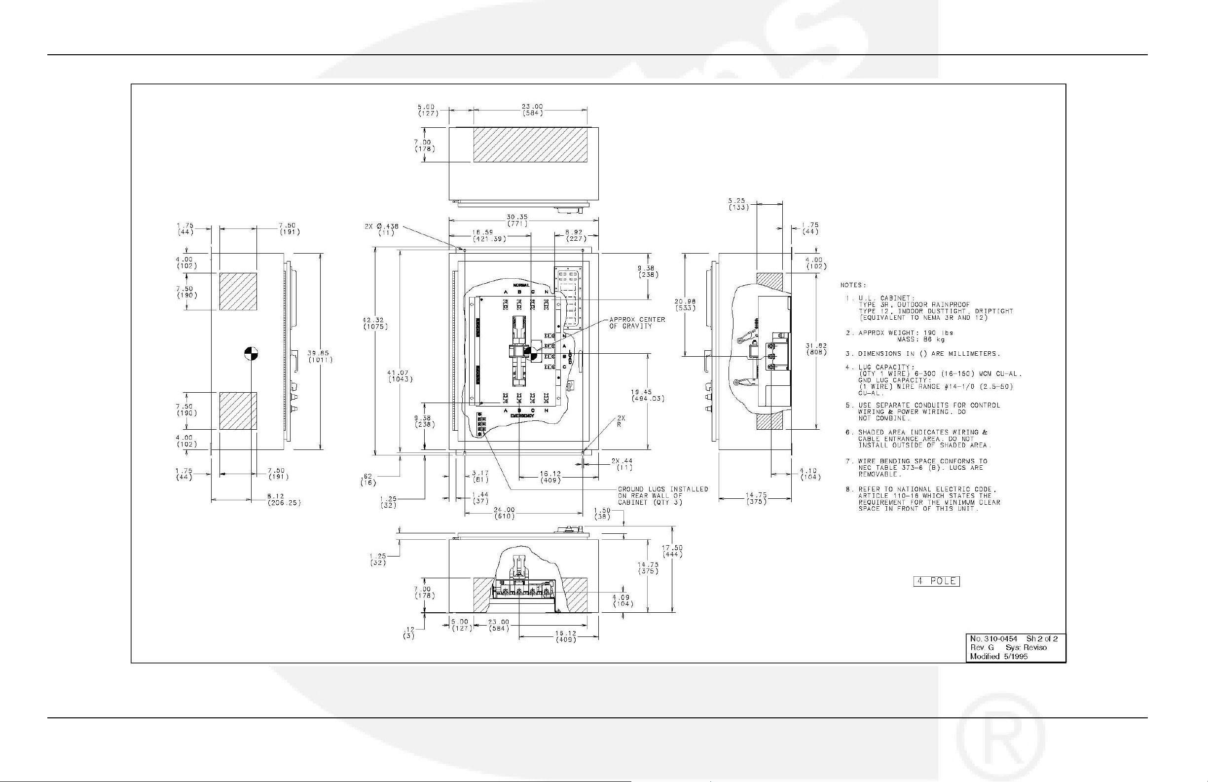
FIGURE 46. NEMA 3R AND 12 CONTROL BOX OUTLINE DRAWING 310-0454, 150-225 AMP (SHEET 2 OF 2)
962-0617 (Issue 5) 57
Page 64
Appendix A. Interconnect Diagrams and Outline Drawings 4-2010
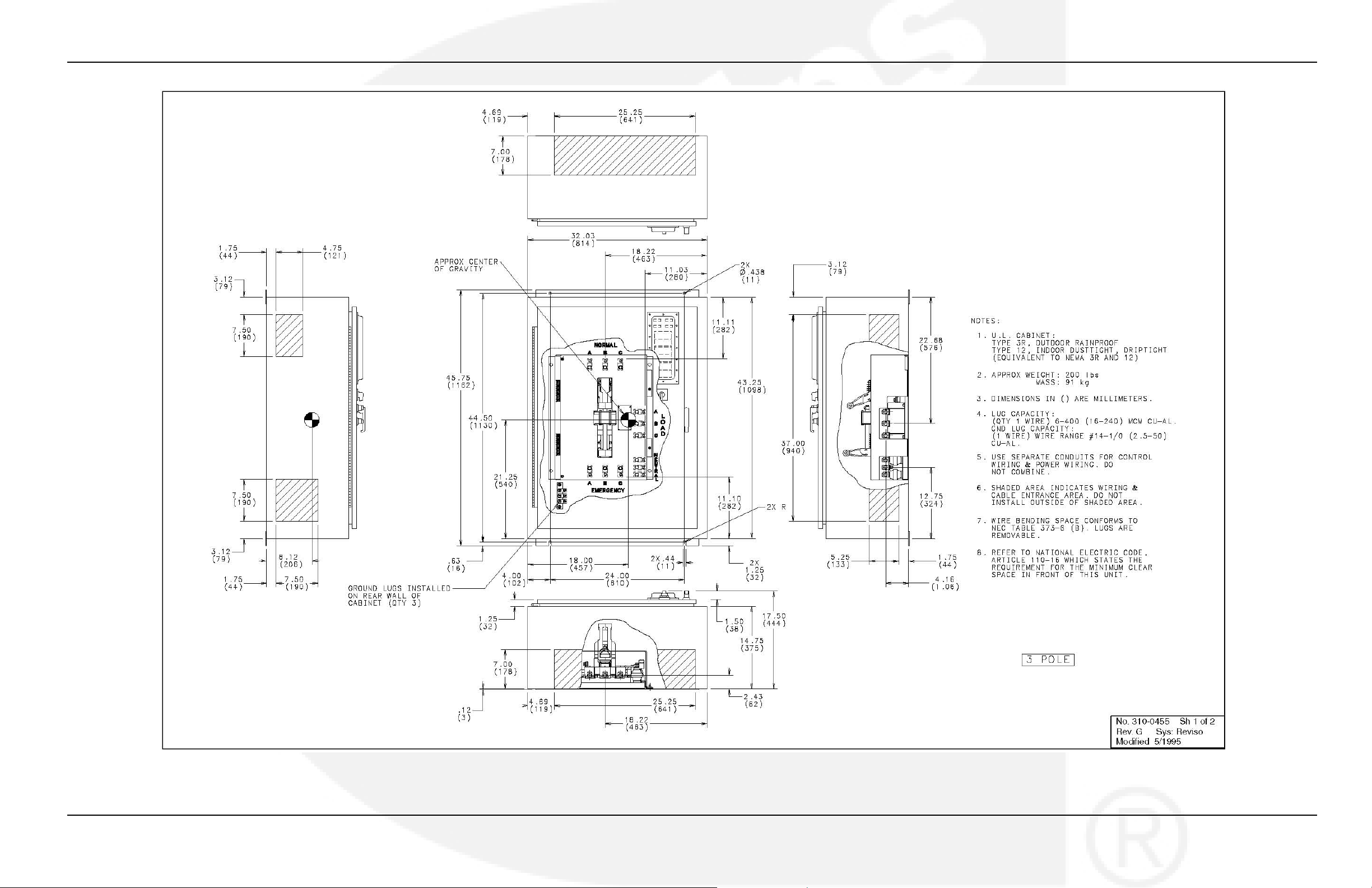
FIGURE 47. NEMA 3R AND 12 CONTROL BOX OUTLINE DRAWING 310-0455, 260 AMP (SHEET 1 OF 2)
58 962-0617 (Issue 5)
Page 65
4-2010 Appendix A. Interconnect Diagrams and Outline Drawings
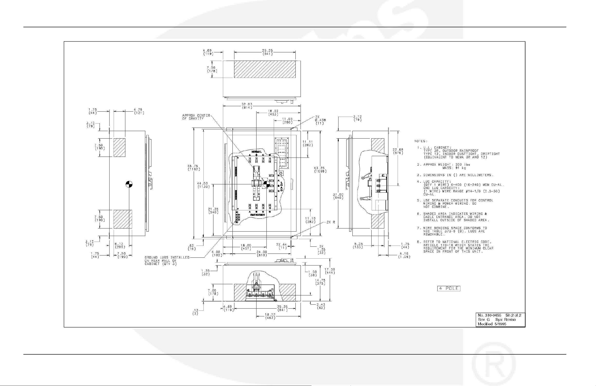
FIGURE 48. NEMA 3R AND 12 CONTROL BOX OUTLINE DRAWING 310-0455, 260 AMP (SHEET 2 OF 2)
962-0617 (Issue 5) 59
Page 66
Appendix A. Interconnect Diagrams and Outline Drawings 4-2010
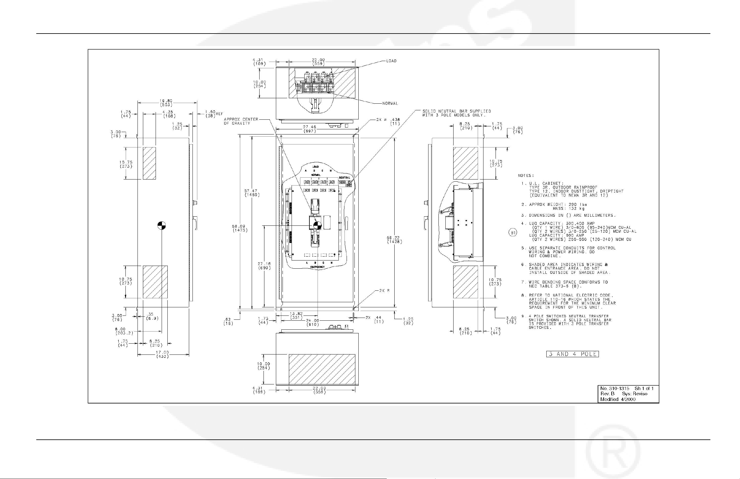
FIGURE 49. NEMA 3R AND 12 CONTROL BOX OUTLINE DRAWING 310-1315, 300-600 AMP
60 962-0617 (Issue 5)
Page 67
4-2010 Appendix A. Interconnect Diagrams and Outline Drawings
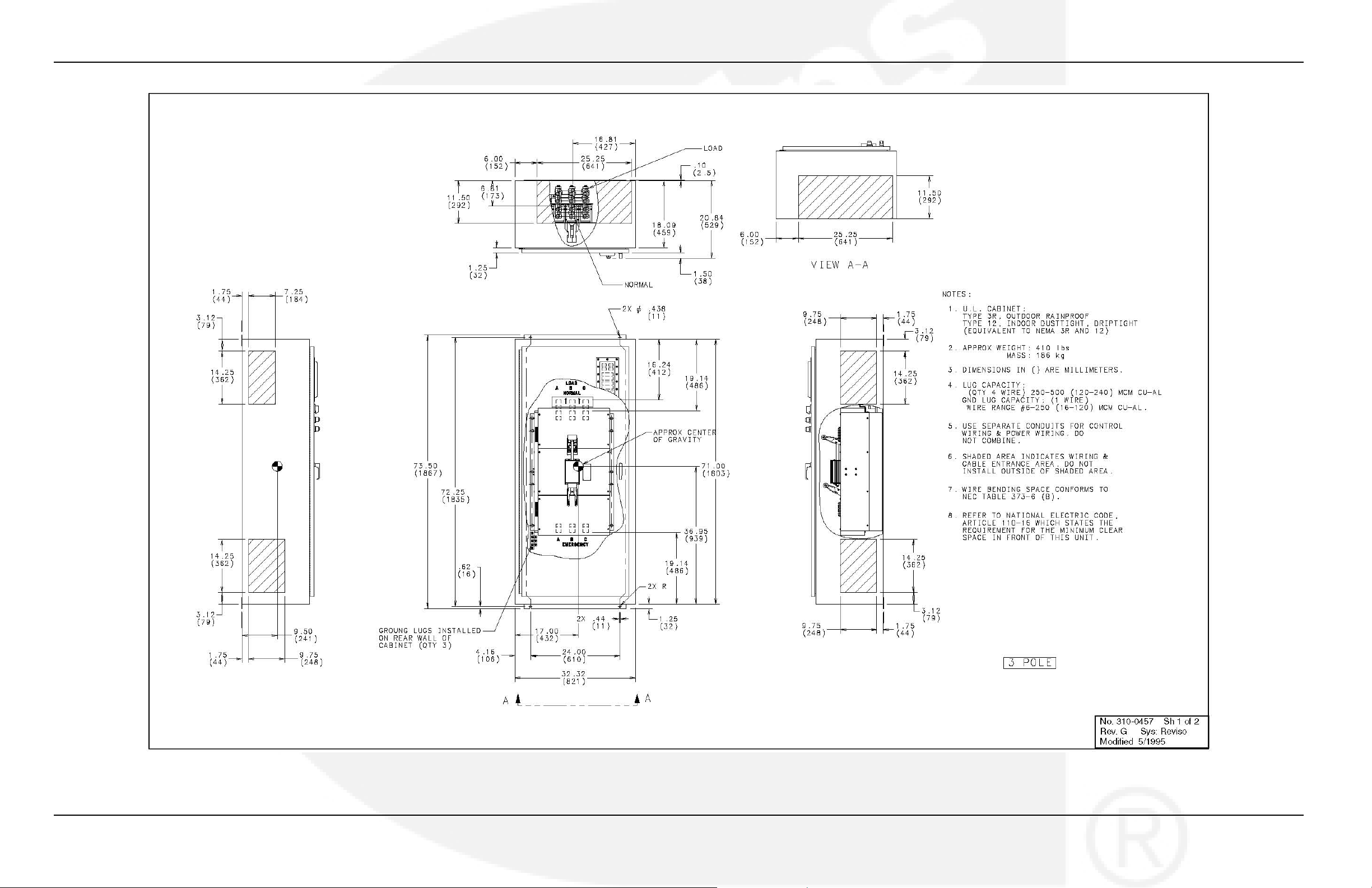
FIGURE 50. NEMA 3R AND 12 CONTROL BOX OUTLINE DRAWING 310-0457, 800 AND 1000 AMP (SHEET 1 OF 2)
962-0617 (Issue 5) 61
Page 68

Appendix A. Interconnect Diagrams and Outline Drawings 4-2010
FIGURE 51. NEMA 3R AND 12 CONTROL BOX OUTLINE DRAWING 310-0457, 800 AND 1000 AMP (SHEET 2 OF 2)
62 962-0617 (Issue 5)
Page 69
4-2010 Appendix A. Interconnect Diagrams and Outline Drawings
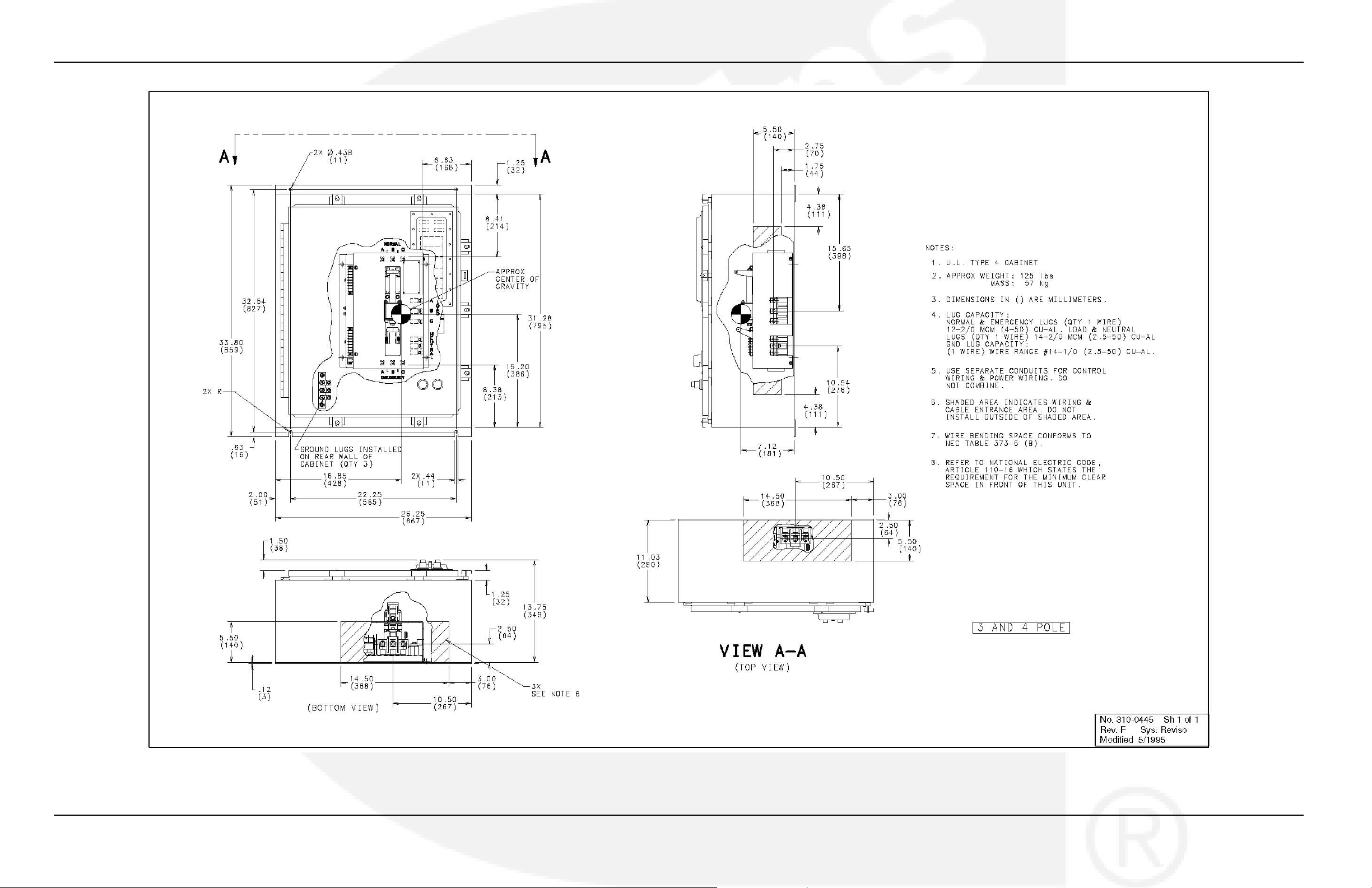
FIGURE 52. NEMA 4 CONTROL BOX OUTLINE DRAWING 310-0445, 40-125 AMP
962-0617 (Issue 5) 63
Page 70
Appendix A. Interconnect Diagrams and Outline Drawings 4-2010
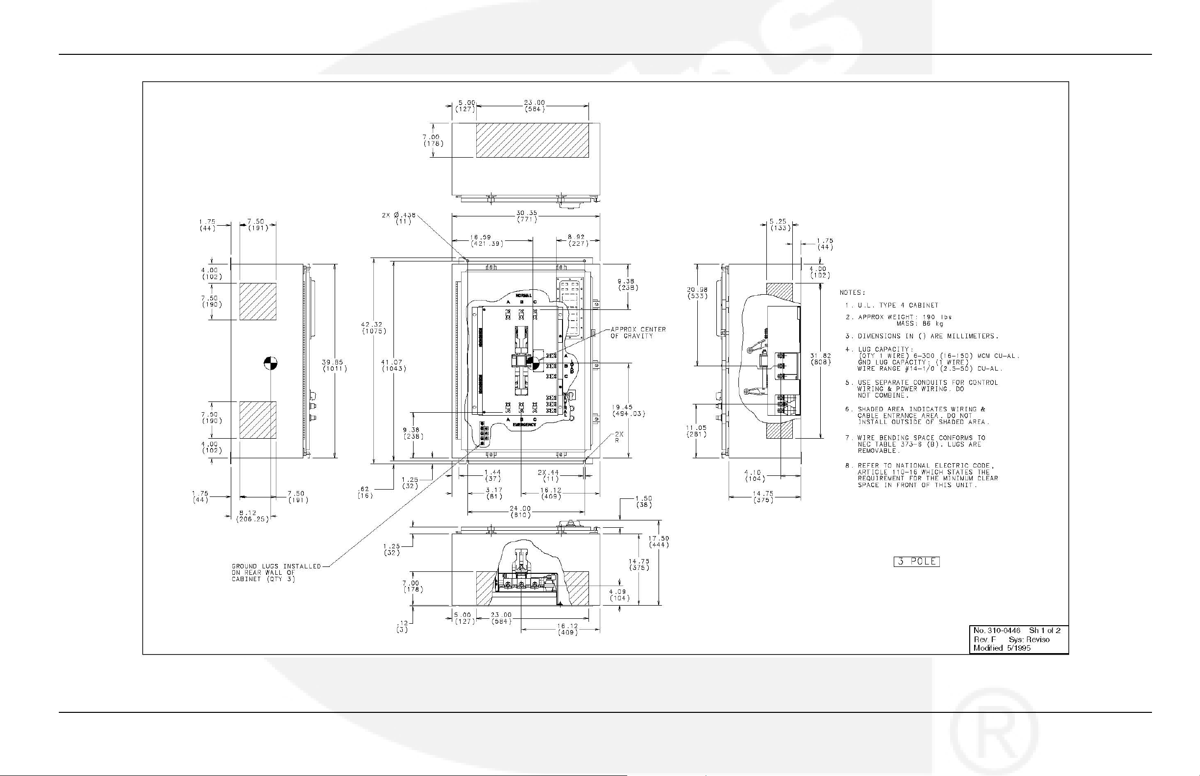
FIGURE 53. NEMA 4 CONTROL BOX OUTLINE DRAWING 310-0446, 150-225 AMP (SHEET 1 OF 2)
64 962-0617 (Issue 5)
Page 71
4-2010 Appendix A. Interconnect Diagrams and Outline Drawings
FIGURE 54. NEMA 4 CONTROL BOX OUTLINE DRAWING 310-0446, 150-225 AMP (SHEET 2 OF 2)
962-0617 (Issue 5) 65
Page 72
Appendix A. Interconnect Diagrams and Outline Drawings 4-2010
FIGURE 55. NEMA 4 CONTROL BOX OUTLINE DRAWING 310-0447, 260 AMP (SHEET 1 OF 2)
66 962-0617 (Issue 5)
Page 73
4-2010 Appendix A. Interconnect Diagrams and Outline Drawings
FIGURE 56. NEMA 4 CONTROL BOX OUTLINE DRAWING 310-0447, 260 AMP (SHEET 2 OF 2)
962-0617 (Issue 5) 67
Page 74
Appendix A. Interconnect Diagrams and Outline Drawings 4-2010
FIGURE 57. NEMA 4 CONTROL BOX OUTLINE DRAWING 310-1316, 300-600 AMP
68 962-0617 (Issue 5)
Page 75
4-2010 Appendix A. Interconnect Diagrams and Outline Drawings
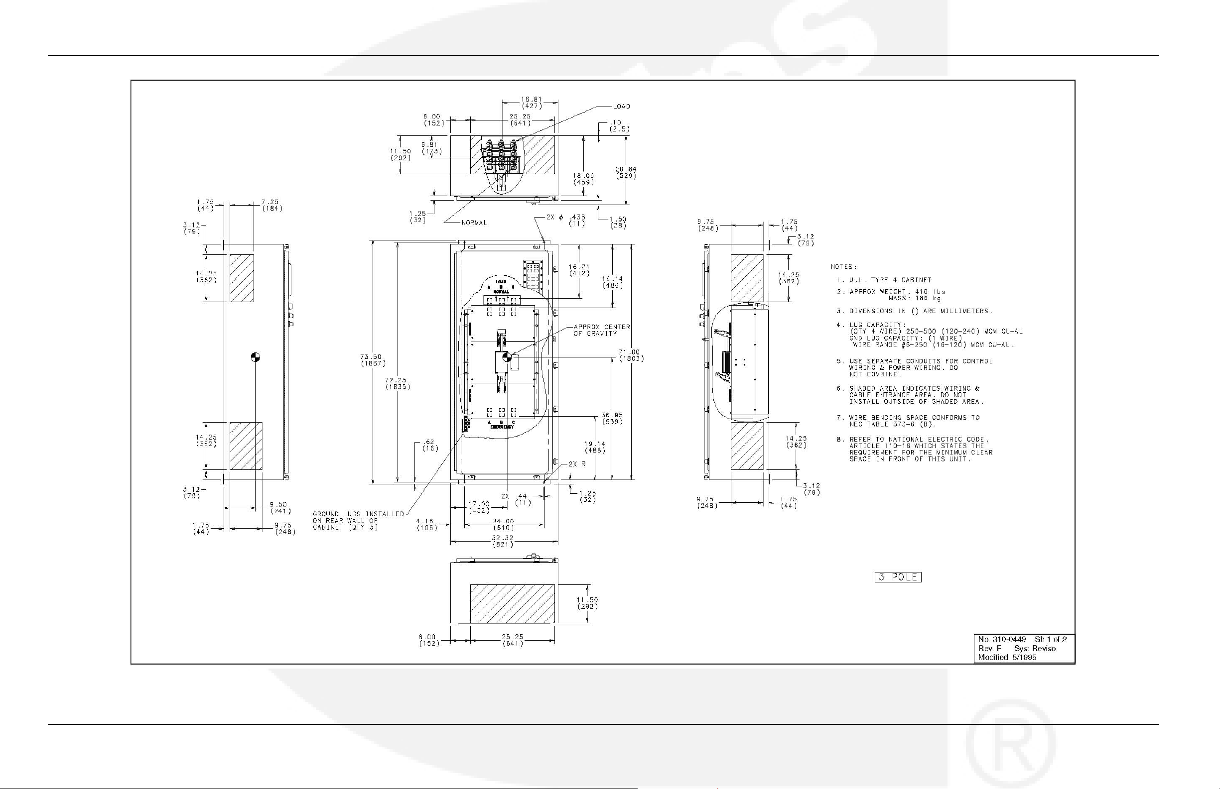
FIGURE 58. NEMA 4 CONTROL BOX OUTLINE DRAWING 310-0449, 800 AND 1000 AMP (SHEET 1 OF 2)
962-0617 (Issue 5) 69
Page 76
Appendix A. Interconnect Diagrams and Outline Drawings 4-2010
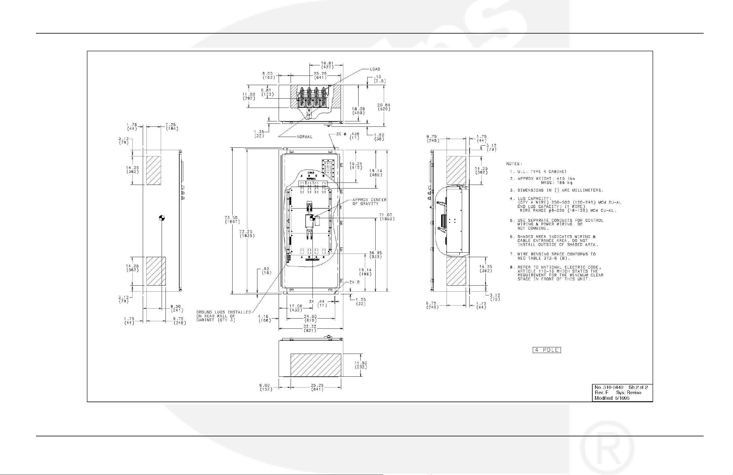
FIGURE 59. NEMA 4 CONTROL BOX OUTLINE DRAWING 310-0449, 800 AND 1000 AMP (SHEET 2 OF 2)
70 962-0617 (Issue 5)
Page 77
4-2010 Appendix A. Interconnect Diagrams and Outline Drawings
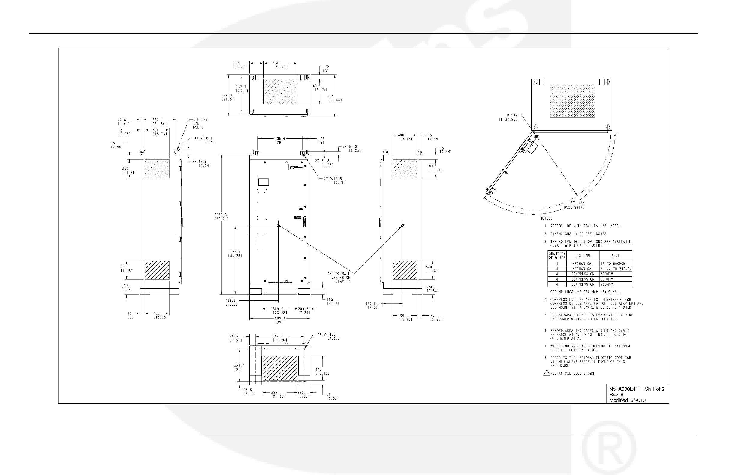
FIGURE 60. NEMA 1, 3R, 4, AND 12 CONTROL BOX OUTLINE DRAWING A030L411, 1200 AMP (SHEET 1 OF 2)
962-0617 (Issue 5) 71
Page 78
Appendix A. Interconnect Diagrams and Outline Drawings 4-2010
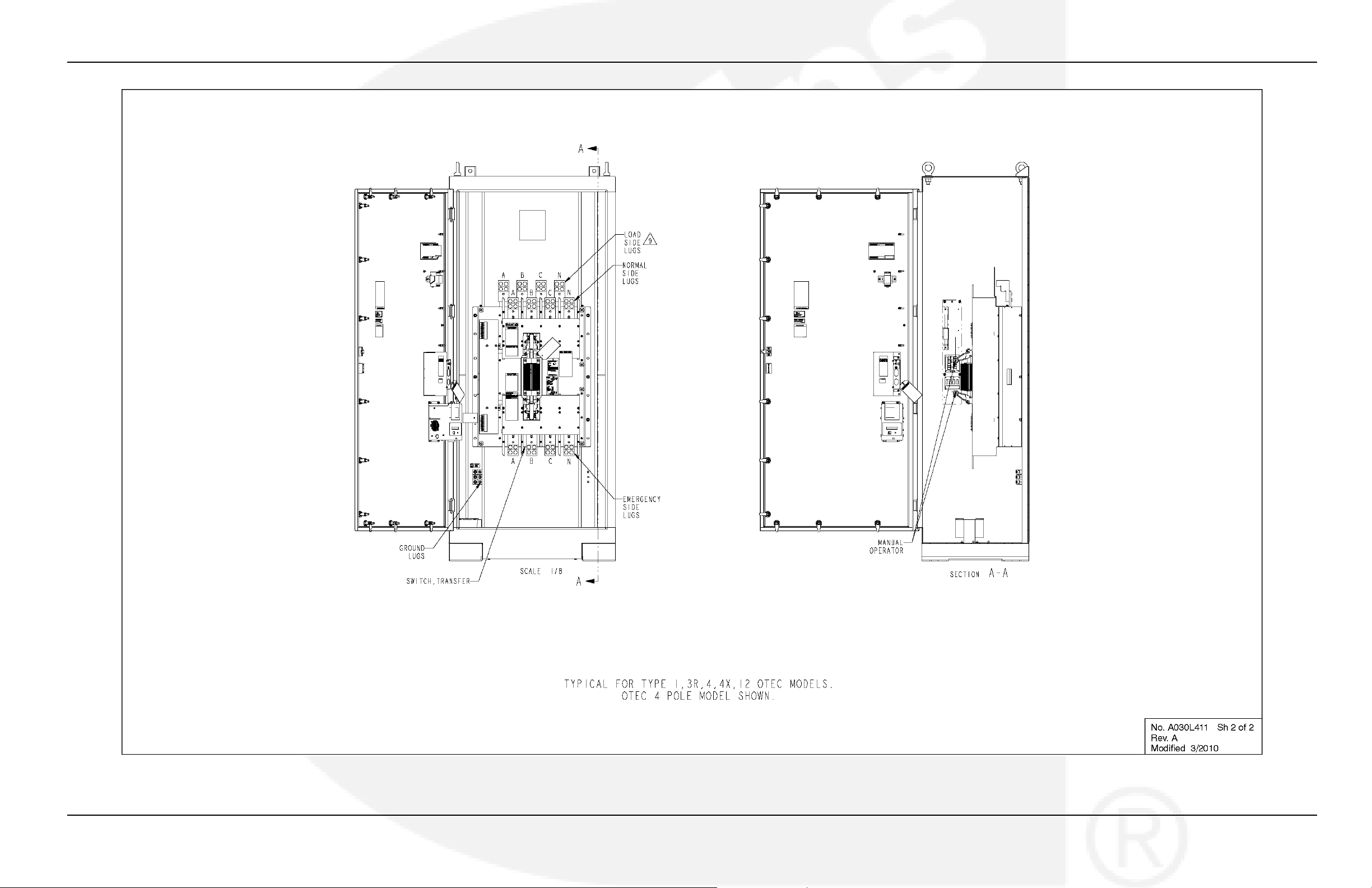
FIGURE 61. NEMA 1, 3R, 4, AND 12 CONTROL BOX OUTLINE DRAWING A030L411, 1200 AMP (SHEET 2 OF 2)
72 962-0617 (Issue 5)
Page 79

Page 80

Cummins Power Generation
1400 73rd Ave. NE
Minneapolis, MN 55432 USA
Phone 1 763 574 5000
Toll-free 1 800 888 6626
Fax 1 763 574 5298
Copyright © 2010 Cummins Power Generation, Inc. All rights reserved.
Cummins, Onan, the "C" logo, and "Performance you rely on." are
trademarks of Cummins Inc.
 Loading...