

Page 1

InstallationInstallation ManualManual
Home Standby Power Generator Set
GSBB (Spec A-D)
GSBC (Spec B-D)
English
Original Instructions 6-2016 A029V088 (Issue 22)
Page 2

Page 3

Table of Contents
1. IMPORTANT SAFETY INSTRUCTIONS ...................................................................................... 1
1.1 Save These Instructions ........................................................................................................ 1
1.2 General Precautions .............................................................................................................. 1
1.3 Generator Voltage is Deadly .................................................................................................. 1
1.4 Engine Exhaust is Deadly ...................................................................................................... 2
1.5 Fuel is Flammable and Explosive .......................................................................................... 2
1.6 Batteries Can Explode............................................................................................................ 2
1.7 Moving Parts Can Cause Severe Personal Injury or Death .................................................. 3
1.8 The Hazards of Carbon Monoxide.......................................................................................... 3
1.8.1 What Is Carbon Monoxide Poisoning? ........................................................................ 3
1.8.2 What Are the Special Risks of CO Near the Home?................................................... 3
1.8.3 Only You Can Protect Yourself From CO Poisoning!.................................................. 3
2. INTRODUCTION............................................................................................................................ 5
2.1 About this Manual................................................................................................................... 5
2.2 Model Specifications............................................................................................................... 5
2.3 Information For After Installation............................................................................................. 8
3. STEP-BY-STEP OUTLINE OF INSTALLATION............................................................................ 9
3.1 Pre-Installation Considerations............................................................................................... 9
3.1.1 Installation Codes and Standards for Safety ............................................................. 10
3.1.2 Required Items for Installation................................................................................... 10
3.1.3 Choosing A Transfer Switch ...................................................................................... 12
3.2 Generator Set Installation Requirements.............................................................................. 16
3.3 Generator Set Installation Suggestions/Guidelines.............................................................. 16
3.4 Preparing the Site................................................................................................................. 16
3.5 Lifting and Moving the Generator Set................................................................................... 17
3.6 Staking the Generator Set in Place ...................................................................................... 17
3.7 Electrical Wiring Connections............................................................................................... 17
3.7.1 AC Power Supply Connections.................................................................................. 18
3.7.2 Grounding .................................................................................................................. 19
3.7.3 Automatic Transfer Switch......................................................................................... 20
3.7.4 Heater and Outlet Connections.................................................................................. 21
3.7.5 Operator Panel........................................................................................................... 21
3.7.6 Load Shed Communications Wires............................................................................ 23
3.7.7 Ethernet Connections Wire........................................................................................ 26
3.7.8 Battery ....................................................................................................................... 26
3.8 Fuel System.......................................................................................................................... 27
3.8.1 Fuel Line Connections ............................................................................................... 28
3.8.2 Fuel Line Connections (Model 14GSBB-6716B Only)............................................... 29
3.8.3 Natural Gas Fuel System........................................................................................... 29
3.8.4 Propane Fuel System ................................................................................................ 31
iA029V088 (Issue 22) Copyright © 2016 Cummins Inc.
Page 4

Table of Contents 6-2016
3.8.5 Testing the Fuel System for Leaks ............................................................................ 36
3.9 Engine Exhaust..................................................................................................................... 36
4. OPTIONAL INTERNET/EMAIL INTERFACE DESCRIPTIONS................................................... 39
4.1 Introduction .......................................................................................................................... 39
4.2 Screen Descriptions ............................................................................................................. 40
4.2.1 Setting Time and Date .............................................................................................. 40
4.2.2 Set Exercise Schedule .............................................................................................. 40
4.2.3 Load Control (Management) ..................................................................................... 41
4.2.4 Event Log .................................................................................................................. 41
4.2.5 Fault Log ................................................................................................................... 42
4.2.6 Network Setup Screen Descriptions.......................................................................... 42
4.2.7 Email Setup Screen Descriptions .............................................................................. 43
4.2.8 Saving Changes......................................................................................................... 44
5. OPTIONAL INTERNET/EMAIL INTERFACE SETUP.................................................................. 45
5.1 Network Connectivity Options............................................................................................... 45
5.2 Material/Cable Routing ......................................................................................................... 45
5.3 Network Information Needed For Setup ............................................................................... 45
5.3.1 Network Router.......................................................................................................... 45
5.3.2 Email/Internet Service Provider (ISP)........................................................................ 45
5.4 In-Home Network Access to the Generator Set .................................................................. 46
5.5 Setting Up Internet Access and E-mail Alerts....................................................................... 49
5.6 Port Forwarding ................................................................................................................... 51
5.7 Remote Viewing IP Options Static IP .................................................................................. 51
5.8 Dynamic IP Monitoring ......................................................................................................... 52
5.9 Help Hotline ......................................................................................................................... 52
5.10 Frequently Asked Questions .............................................................................................. 52
6. OPERATION ............................................................................................................................... 55
6.1 3 Position Switch................................................................................................................... 55
6.2 In-Home Operator Panel ...................................................................................................... 55
6.2.1 BACK Button.............................................................................................................. 56
6.2.2 START STOP Button................................................................................................. 56
6.2.3 Standby ON/OFF Button............................................................................................ 56
6.3 Typical Operation.................................................................................................................. 57
6.3.1 Normal Operation: Utility Power Available and Connected ....................................... 60
6.3.2 Emergency Operation: Utility Power Interrupted ....................................................... 61
6.4 To Enable/Disable Standby ................................................................................................. 62
6.5 To Manually Start/Stop Generator Set ................................................................................ 62
6.6 Fault, Maintenance and New Event Screens ....................................................................... 63
6.6.1 Fault Screen............................................................................................................... 63
6.6.2 Maintenance Due Screen .......................................................................................... 64
6.6.3 New Event Screen ..................................................................................................... 64
6.7 Genset Status ...................................................................................................................... 65
6.8 Display Setup and Software Info .......................................................................................... 66
6.8.1 Brightness and Contrast ............................................................................................ 66
ii A029V088 (Issue 22)Copyright © 2016 Cummins Inc.
Page 5

Table of Contents6-2016
6.8.2 Software Info.............................................................................................................. 67
6.9 Event Log.............................................................................................................................. 68
6.9.1 To Check Log of Last 20 Events................................................................................ 68
6.9.2 List of Recordable Events.......................................................................................... 68
6.10 Fault Log............................................................................................................................. 69
6.11 Exercise Settings ............................................................................................................... 70
6.12 Time Setup ......................................................................................................................... 71
6.13 Load Management.............................................................................................................. 72
6.13.1 Automatic Load Management.................................................................................. 72
6.13.2 Manual Load Management ...................................................................................... 73
7. STARTUP AND CONFIGURATION............................................................................................. 75
7.1 Installation Review ............................................................................................................... 75
7.2 Startup ................................................................................................................................. 75
7.3 Fuel Solenoid - First Startup................................................................................................. 76
7.4 Generator Set Configuration ................................................................................................ 76
7.5 Transfer Switch Configuration ............................................................................................. 78
7.6 Transfer Switch Parameter Adjustments ............................................................................. 80
7.7 Generator Adjustments......................................................................................................... 81
7.7.1 To Adjust the Output Voltage..................................................................................... 81
7.7.2 To Calibrate the Display Meter ................................................................................. 82
8. COMMUNICATION TROUBLESHOOTING................................................................................. 83
8.1 In-Home Network Access to Generator Set Troubleshooting .............................................. 83
8.2 Remote Internet Access to Generator Set Troubleshooting ................................................ 84
8.3 Email Alert Troubleshooting ................................................................................................. 85
APPENDIX A. OUTLINE AND SYSTEM DRAWINGS...................................................................... 89
iiiA029V088 (Issue 22) Copyright © 2016 Cummins Inc.
Page 6

Table of Contents 6-2016
This page is intentionally blank.
iv A029V088 (Issue 22)Copyright © 2016 Cummins Inc.
Page 7

1 IMPORTANT SAFETY INSTRUCTIONS
1.1 Save These Instructions
This manual contains important instructions for the generator set that should be followed during
installation, operation and maintenance of the generator and batteries.
Thoroughly read the Operator Manual before operating the generator set. Safe operation and top
performance can only be obtained when equipment is properly operated and maintained.
The following symbols in this manual alert you to potential hazards to the operator, service person and
equipment.
DANGER
Alerts you to an immediate hazard that will result in severe personal injury or death.
WARNING
Alerts you to a hazard or unsafe practice that can result in severe personal injury or death.
CAUTION
Alerts you to a hazard or unsafe practice that can result in personal injury or equipment damage.
1.2 General Precautions
• Keep ABC fire extinguishers handy.
• Make sure all fasteners are secure and torqued properly.
• Keep the generator set and its compartment clean. Do not store any items in the genset
compartment.
◦ Excess oil, oily rags (etc.) can catch fire.
◦ Dirt and gear stowed in the compartment will restrict cooling air flow.
• Before working on the generator set, move the Stop Switch (S2) to the Stop position, disconnect the
remote harness (P7) to disable the ATS mounted charger and then remove the negative (-) battery
cable to prevent starting.
• Use caution when making adjustments while the generator set is running, hot, moving or when parts
are electrically live, as all situations may cause personal injury or death.
• Used engine oil has been identified by some state and federal agencies as causing cancer or
reproductive toxicity. Do not ingest, inhale or come into contact with used oil or its vapors.
• Do not work on the generator set when mentally or physically fatigued or after consuming alcohol or
drugs.
1.3 Generator Voltage is Deadly
• Generator output connections must be made by a trained and experienced electrician in accordance
with all applicable codes.
1A029V088 (Issue 22) Copyright © 2016 Cummins Inc.
Page 8

1. IMPORTANT SAFETY INSTRUCTIONS 6-2016
• This standby generator set and the public utility may only be connected to the house circuits by
means of the automatic transfer switch.
◦ Improper connections can lead to electrocution of utility workers and damage to equipment.
• Use caution when working on live electrical equipment. Remove jewelry, make sure clothing and
shoes are dry and stand on a dry wooden platform.
1.4 Engine Exhaust is Deadly
• See What Is Carbon Monoxide Poisoning? to learn the symptoms of Carbon Monoxide poisoning.
• This generator set is for outdoor installation only.
◦ It must be located well away from doors, windows, other openings into the house and where
the exhaust gases will disperse away from the house.
1.5 Fuel is Flammable and Explosive
• Keep flames, cigarettes, sparks, pilot lights, electrical arc-producing equipment, switches and all
other sources of ignition well away from areas where fuel fumes are present and areas sharing
ventilation.
• Fuel lines must be secured, free of leaks and separated or shielded from electrical wiring.
• Leaks can lead to explosive accumulations of gas. Prevent leaks and the accumulation of gas.
◦ A "rotten egg" smell indicates a possible Natural Gas or Propane leak:
▪ Natural Gas rises when released and can accumulate under hoods and inside housings
and buildings.
▪ Propane sinks when released and can accumulate inside housings and basements and
other below-grade spaces.
1.6 Batteries Can Explode
Batteries can explode, causing severe skin and eye burns and can release toxic electrolytes.
• Wear safety glasses.
• Do not smoke.
• Do not dispose of the battery in a fire.
◦ The battery is capable of exploding.
• Do not open or mutilate the battery.
◦ Released electrolytes have been known to be harmful to the skin and eyes and to be toxic.
• Batteries present the risk to high short circuit current:
◦ Remove watches, rings or other metal objects and use tools with insulated handles.
• To prevent arcing when disconnecting the battery:
◦ Move the Stop Switch (S2) to the Stop position, disconnect the remote harness (P7) to disable
the ATS mounted charger and then remove the negative (-) battery cable to prevent starting.
• To prevent arcing when reconnecting the battery:
◦ First, reconnect the positive (+) cable, then the negative (-) cable, and finally reconnect the
battery charger.
2 A029V088 (Issue 22)Copyright © 2016 Cummins Inc.
Page 9

1. IMPORTANT SAFETY INSTRUCTIONS6-2016
• When replacing the generator set battery, always replace it with a battery as specified in the Model
Specifications section of this manual.
1.7 Moving Parts Can Cause Severe Personal Injury or Death
• Do not wear loose clothing or jewelry near moving parts such as fans.
• Keep hands away from moving parts.
• Keep guards in place, over fans.
1.8 The Hazards of Carbon Monoxide
Engine-driven generators can produce harmful levels of carbon monoxide that can injure or kill you.
1.8.1 What Is Carbon Monoxide Poisoning?
Carbon Monoxide (CO) is an odorless, colorless, tasteless and non-irritating gas. You cannot see it or
smell it. Red blood cells, however, have a greater affinity for CO than for Oxygen. Therefore, exposure
even to low levels of CO for a prolonged period can lead to asphyxiation (lack of Oxygen) resulting in
death. Mild effects of CO poisoning include eye irritation, dizziness, headaches, fatigue and the inability to
think clearly. More extreme symptoms include vomiting, seizures and collapse.
1.8.2 What Are the Special Risks of CO Near the Home?
Residents can be exposed to lethal levels of CO when the genset is running. Depending on air
temperature and wind, CO can accumulate in or near the home.
To protect yourself and others from the dangers of CO poisoning, it is recommended that reliable and
approved CO detector alarms be installed in the home.
WARNING
Carbon Monoxide (CO) gas can cause nausea, fainting or death.
1.8.3 Only You Can Protect Yourself From CO Poisoning!
• Locate the generator in an area where there are no windows, doors or other access points into the
home.
• Make sure all CO detectors are working properly.
• Pay attention to the signs of CO poisoning.
• Check the exhaust system for corrosion, obstruction and leaks each time you start the generator set
and every eight hours if you run it continuously.
3A029V088 (Issue 22) Copyright © 2016 Cummins Inc.
Page 10

1. IMPORTANT SAFETY INSTRUCTIONS 6-2016
This page is intentionally blank.
4 A029V088 (Issue 22)Copyright © 2016 Cummins Inc.
Page 11

2 Introduction
This generator set application is intended for stationary emergency use.
Important note for Brazil applications: The manufacturer warns that the installation, operation and
maintenance of equipment by the user must fully comply with the Manual's guidelines and current
Brazilian laws, including those of the Brazilian Agency of Petroleum, Natural Gas and Fuels (ANP) and the
Brazilian Energy Agency (ANEEL).
2.1 About this Manual
This manual is a guide for the installation of the generator set models listed on the front cover. Proper
installation is essential for top performance, reliable operation and safety. Read through this manual
before starting the installation.
The installation must comply with all applicable building codes.
See the generator set Operator Manual (A029V089) for operation and maintenance and the Service
Manual (A030A239) for service.
Manuals are updated from time to time to reflect changes in the equipment and its specifications.
The most up-to-date version of this manual will be found on the QuickServe website
(https://quickserve.cummins.com/info/index.html).
NOTICE
NOTICE
2.2 Model Specifications
TABLE 1. GSBB AND GSBC MODEL VARIATIONS
Product Description
20GSBB-6713A\B 60 Hz Warm
20GSBB-6714A\B 60 Hz Cold *
14GSBB-6716A\B 50 Hz (AU/NZ)
20GSBB-6717A\20GSBC-6927B 60 Hz CSA Cold *
20GSBB-6714D 60 Hz Cold *
20GSBC-6727D 60 Hz CSA Cold *
* Includes an engine oil heater.
NOTICE
See the Cold Weather Specifications Table for recommendations.
5A029V088 (Issue 22) Copyright © 2016 Cummins Inc.
Page 12

2. Introduction 6-2016
TABLE 2. COLD WEATHER SPECIFICATIONS TABLE
60 Hz 50 Hz
Propane Vapor Natural Gas Propane Vapor Natural Gas
Operating Temperature Range
Above 40 °F (4 °C) and low
humidity
High humidity Alternator drying heater recommended.
Below 20 °F (-7 °C) Additional oil heater recommended for starting. Factory-installed model available.
Below 0 °F (-18 °C) Additional accessory breather shield/shroud required to avoid possible engine
Below -10 °F (-23 °C) Additional accessory battery blanket recommended for starting.
Dimensions
Weight (With Oil) 540 lbs (245 kg)
Size (L x W x H) 48 x 43 x 34.6 in (1219 x 864 x 880 mm)
Noise 62 dB(A) at 23 ft (7 m) at normal load. (Normal load is equal to the typical
No dryers or starting aids required.
damage. See warranty statement.
TABLE 3. GENERATOR SET SPECIFICATIONS TABLE
60 Hz 50 Hz
Propane Vapor Natural Gas Propane Vapor Natural Gas
household consumption of 3 KW.)
TABLE 4. FUEL SPECIFICATIONS TABLE (SPEC A AND CANADIAN GSBB SPEC B)
60 Hz 50 Hz
Propane Vapor Natural Gas Propane Vapor Natural Gas
Fueling
1/2 Load 132,500 Btu/Hr
53 ft3/Hr
Full Load 275,000 Btu/Hr
109 ft3/Hr
Fuel Pressure (all loads)
As measured at genset fuel
regulator service port
Tank Size Contact your local gas company to verify the tank size required for your application.
7-11 inches WC 5-11 inches WC 7-11 inches WC 5-11 inches WC
135,000 Btu/Hr
135 ft3/Hr
240,000 Btu/Hr
233 ft3/Hr
122,000 Btu/Hr
48 ft3/Hr
229,000 Btu/Hr
91 ft3/Hr
114,000 Btu/Hr
111 ft3/Hr
213,000 Btu/Hr
207 ft3/Hr
6 A029V088 (Issue 22)Copyright © 2016 Cummins Inc.
Page 13

Fueling
2. Introduction6-2016
TABLE 5. FUEL SPECIFICATIONS TABLE (US GSBB SPEC B AND CANADIAN GSBC SPEC B)
60 Hz 50 Hz
Propane Vapor Natural Gas Propane Vapor Natural Gas
1/2 Load 195,000 Btu/Hr
78 ft3/Hr
Full Load 310,000 Btu/Hr
123 ft3/Hr
Fuel Pressure (all loads)
As measured at genset fuel
regulator service port
Tank Size Contact your local gas company to verify the tank size required for your application.
Engine 2 Cylinder-V Twin, OHV, Air-Cooled, 4-Stroke, Spark Ignited, 3600 RPM
Displacement 60.59 in3(993 cc)
Spark Plug Gap .020 inch (.51 mm)
Spark Plug Torque 15 ft-lb (20 N-m)
Intake and Exhaust Cold Valve
Lash
(Measure at 0.25" (6.35mm)
past top dead center)
12-14 inches WC 5-7 inches WC 12-14 inches WC 5-7 inches WC
TABLE 6. ENGINE SPECIFICATIONS TABLE
Propane Vapor Natural Gas Propane Vapor Natural Gas
0.004-0.006 inch (0.10 - 0.15 mm)
177,000 Btu/Hr
172 ft3/Hr
255,000 Btu/Hr
248 ft3/Hr
60 Hz 50 Hz
165,000 Btu/Hr
66 ft3/Hr
262,500 Btu/Hr
104 ft3/Hr
150,000 Btu/Hr
146 ft3/Hr
217,000 Btu/Hr
211 ft3/Hr
Oil Capacity Approximately 80 oz (2.3 Liters)
Oil Recommendation
(See Operator Manual)
Generator Brush-Type, 2-Pole Rotating Field, Single Bearing
Power (kVA) --- --- 13.5 13.5
Rated Voltage (V) 120/240 120/240 115/230 115/230
Rated Current (Amps) 162/81.25 144/72 117.4/58.7 117.4/58.7
Phase Type Single Phase
Circuit Breaker (Amps) 100 100 60 60
5W-30 Synthetic Engine Oil
TABLE 7. GENERATOR SPECIFICATIONS TABLE
60 Hz 50 Hz
Propane Vapor Natural Gas Propane Vapor Natural Gas
7A029V088 (Issue 22) Copyright © 2016 Cummins Inc.
Page 14

2. Introduction 6-2016
60 Hz 50 Hz
Propane Vapor Natural Gas Propane Vapor Natural Gas
De-rating Guidelines: Maximum wattage or maximum current are subject to and limited by such factors as fuel Btu
content, ambient temperature, altitude, engine power and condition, etc. Full rated power is available at 60 °F (15.5
°C) at sea level. De-rate 3.5% for each 1000 ft (304.8 m) above sea level and 3% for each 10 °F (5.5 °C) increase in
ambient temperature above 60 °F (15.5 °C).This generator is rated in accordance with UL 2200 (Stationary Engine
Generator Assemblies) or CSA C22.2 No. 100-04 (Motors and Generators). The maximum continuous current values
that are listed on the generator set nameplate and specification tables occur at the lower limit of acceptable voltage.
Maximum current occurs at 108 and 216 volts, 10% below nominal voltage 120/240. The voltage set point of this
generator set can be adjusted from the operator panel if desired. Refer to the Operator manual procedure To Adjust
the Output Voltage.
TABLE 8. CONTROL SPECIFICATIONS TABLE
60 Hz 50 Hz
Propane Vapor Natural Gas Propane Vapor Natural Gas
Controller Integrated Microprocessor-Based Engine, Generator, Transfer Switch Controller
TABLE 9. DC SYSTEM SPECIFICATIONS TABLE
60 Hz 50 Hz
Propane Vapor Natural Gas Propane Vapor Natural Gas
DC System
Nominal Battery Voltage 12 Volts DC
Battery Group 26 R
Battery Type Maintenance Free
Minimum Cold Crank Amps 545
2.3 Information For After Installation
WARNING
Improper installation can result in severe personal injury, death and damage to equipment. The
installation must comply with all applicable building codes. It is strongly recommended that the
installer be properly trained and licensed to perform electrical and mechanical equipment
installations, however a person with the proper knowledge and experience in installing electrical
and mechanical equipment installations may also install this genset.
Refer to the GSBB Specifications Sheetfor specific information about the system and its components.
Refer to the Outline and System Drawings for specific information about the installation and wiring
connections.
See the Operator Manual (A029V089) for proper operation and maintenance instructions.
8 A029V088 (Issue 22)Copyright © 2016 Cummins Inc.
Page 15

3 Step-By-Step Outline of Installation
WARNING
The installer is responsible for complying with all applicable installation codes and safety
requirements. See the Installation Codes and Standards section of this manual for more
information.
The following sections create a step-by-step overview of a typical generator set installation.
Review these sections to become familiar with specific procedures and important safety precautions
before beginning the installation.
NOTICE
For information on pre-installation considerations (tools, materials, locating the genset, codes
and standards and specifications) see the Introduction chapter of this manual.
3.1 Pre-Installation Considerations
Before installation begins, certain actions must be considered. Prior coordination will reduce delays and
the amount of time power has to be interrupted.
Areas of consideration:
• The location of the generator set is one of the first decisions to be made, as it affects all other
aspects of the installation, such as:
◦ the length of electric wiring
◦ the length of gas lines
▪ Natural Gas or Propane - both of which must be inspected by the gas utility inspectors
and building inspectors
◦ the site preparation
▪ access to the site
▪ trenches
▪ site preparation materials needed
• Fuel supply pressure.
• The installation cannot be completed without connections to an automatic transfer switch. Decide
where to locate the automatic transfer switch
• Decide what tools and materials will be needed
• Maintain the minimum distance from the Propane tank fill.
◦ Verify the legal minimum distance with local code officials.
• Determine what (if any) accessories will be required for the customer's application. Utility power may
be required at the generator set, make plans accordingly.
9A029V088 (Issue 22) Copyright © 2016 Cummins Inc.
Page 16

3. Step-By-Step Outline of Installation 6-2016
NOTICE
Depending on the locality and use of the generator set, it may be necessary to obtain an air
quality emissions permit before installation begins. Check with local pollution control or air
quality authority to determine whether or not a permit is needed.
3.1.1 Installation Codes and Standards for Safety
WARNING
The generator set installer bears sole responsibility for following all applicable local codes and
regulations.
The following list of Installation Codes and Standards for Safety applies to the installation and operation of
standby generator sets. This list is for reference only and not intended to be inclusive of all applicable
codes and standards. The address of each agency is listed so that copies of the codes may be obtained
for reference. Installation codes and recommendations are subject to change, and may vary by location or
over time.
TABLE 10. INSTALLATION CODES AND STANDARDS FOR SAFETY RECOMMENDATIONS
NFPA 70 - National Electric Code
NFPA 37 - Installation and Use of Stationary Combustion Engines
and Gas Turbines
NFPA 54 - National Fuel Gas Code
NFPA 58 - Storage and Handling of Liquefied Petroleum Gases
CSA Electrical Bulletin
CSA C22.2 No. 100
CSA C22.2 No. 14
California Administrative Code - Title 25 Chapter 3 State of California
Underwriters Laboratories
UL2200
National Fire Protection Association
470 Atlantic Avenue
Boston, MA 02210
Canadian Standards Association
Housing and Construction Materials Section
178 Rexdale Blvd.
Rexdale, Ontario, Canada M9Q 1R3
Documents Section
P.O. Box 1015
North Highlands, CA 95660
Underwriters Laboratories, Inc.
333 Pfingsten Road
Northbrook, IL 60062-2096
3.1.2 Required Items for Installation
Specific tools and materials are required for the installation of this generator set. These items are
identified in the following sections.
10 A029V088 (Issue 22)Copyright © 2016 Cummins Inc.
Page 17
3.1.2.1 Materials Required
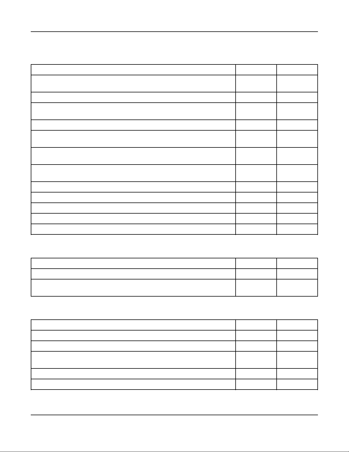
TABLE 11. ELECTRICAL MATERIALS
3. Step-By-Step Outline of Installation6-2016
Required Optional
Appropriately-sized gauge and length AC wires with 75 °C insulation. 4 wires; L1,
L2, N and Gnd.
Appropriate conduit for all AC wires. X
Cummins Power Generation Plug-n-Play harness from Genset to ATS. (1', 50' and
100' lengths available for purchase)
Appropriate conduit for DC communications wires. X
Cummins Power Generation Plug-n-Play harnesses for Generator Set to in home
display (if installing in the house). (1', 50' and 100' lengths available for purchase)
Three conductor 75 °C 300V minimum-rated wiring appropriately sized to 120 volt
GFCI installation or to Alternator/Oil heaters (if equipped).
Appropriately-sized junction box and cover for heater/GFCI wiring (if installing).
Provided on cold weather model.
Code compliant GFCI outlet and "While in Use - Wet Location" cover. X
Cat 5e for Internet installation. X
Two conductor 300V wire (18AWG) per Load Management relay. X
Low Voltage: SPDT relay min 1A 24VAC. X
High Voltage: SPDT relay sized to load (amp and voltage). X
X
X
X
X
X
TABLE 12. MOUNTING MATERIALS
Required Optional
Four base mounting spikes. Provided with generator. X
Cummins Power Generation Installation Wheel Kit is available for easy on-site
generator transportation.
TABLE 13. FUEL MATERIALS
Required Optional
12" Flexible fuel line. Provided with generator. X
UL Listed pipe thread sealant. X
Size Fuel line. NG: 5-7" H20, LP: 12-14" H20 fuel pressure (as measured at genset
fuel regulator service port). See Installation Manual guidelines.
Fuel regulator - as required.
Manual fuel shut-off at Genset (preferred). X
X
X
11A029V088 (Issue 22) Copyright © 2016 Cummins Inc.
Page 18

3. Step-By-Step Outline of Installation 6-2016
TABLE 14. IN-HOME DISPLAY MATERIALS
Required Optional
In-home display. One (1) provided with generator. X
Four wall anchors and screws (no. 6) if mounting on stud wall. X
Standoffs and mounting fasteners if mounting on block or brick wall. X
3.1.2.1.1 Loose Parts Shipped With the Generator
The following loose parts are shipped with the generator set:
• Oil drain hose
• Flexible fuel hose assembly
• Welch plug tied to fuel regulator (US GSBB Spec B and Canadian GSBC Spec B only)
• Four base spikes (ground stakes)
• In-home display
• Two keys
• Literature - Operator Manual (A029V089), Installation Manual (A029V088) and Warranty Statement
3.1.2.2 Tools Required
Use a forklift to move the generator set and set it in place. Alternatively, a one-man hand dolly designed to
fit the generator set base is available to move the generator set and set it in place.
Hand tools required include the following:
• Wire stripper for terminating the communications wires
• Torque wrench
• Jewelers screwdriver
• Allen wrench
• Ratchet set with 10 mm socket and extension
• Two pipe wrenches for gas connections
• Phillips-head and flat-blade screwdrivers
• Ball peen hammer
• Fuel meter (operates down to 5 in. WC)
3.1.3 Choosing A Transfer Switch
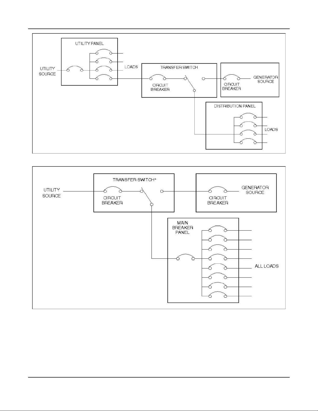
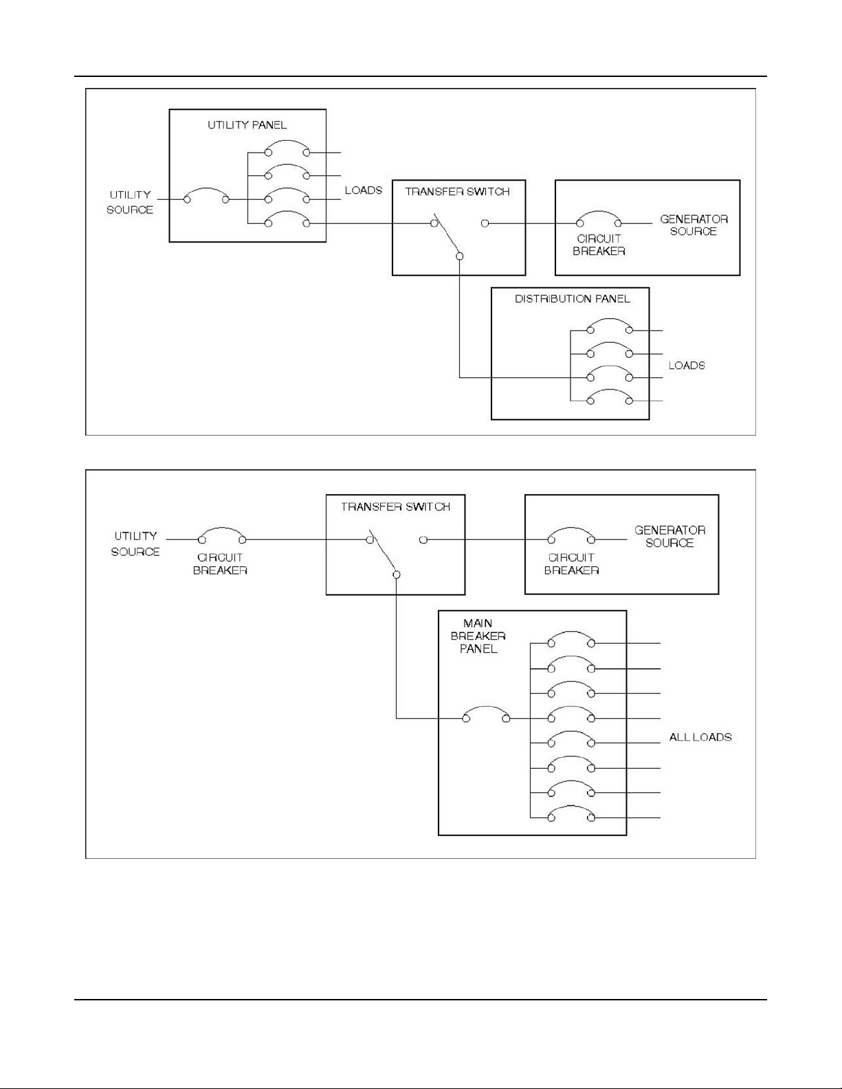
Block diagrams showing partial or full load coverage are shown on the following pages:
• UL 1008 listed, Service Entrance Rated Automatic Transfer Switch (without controller):
◦ RSS 100-6868
◦ RSS 200-6869
• CSA Approved and UL 1008 listed (with controller):
◦ RSS 100-6634
◦ RSS 200-6635
12 A029V088 (Issue 22)Copyright © 2016 Cummins Inc.
Page 19

3. Step-By-Step Outline of Installation6-2016
• UL 1008 listed, Service Entrance Rated (without controller):
◦ RSS 100-6868
◦ RSS 200-6869
NOTICE
If the transfer switch is connected for full load coverage which exceeds the generator set rating,
it may be necessary to shed large loads such as air conditioners.
NOTICE
• The RSS 100 transfer switch models can be connected for full or partial load coverage
equal to the capacity of the generator set.
• The RSS 200 transfer switch models can be connected for full load coverage greater than
the capacity of the generator set.
TABLE 15. TRANSFER SWITCH CONNECTION VS. LOAD COVERAGE
Transfer Switch Model Connection Capabilities
Full Load
(Greater Than Capacity of Genset)
RSS 100-6634 X
RSS 200-6635 X
RSS 100-6868 X
RSS 200-6869 X
Full or Partial Load
(Equal to Capacity of Genset)
NOTICE
Model RSS 100-6634 and RSS 200-6635 transfer switches do not incorporate a utility circuit breaker and
therefore must be connected through a Service Entrance Utility Panel incorporating the utility circuit
breaker.
Perform Generator Set Configurationwhen ready to start up the generator set.
13A029V088 (Issue 22) Copyright © 2016 Cummins Inc.
Page 20
3. Step-By-Step Outline of Installation 6-2016
FIGURE 1. PARTIAL COVERAGE LOAD CONNECTIONS (TRANSFER SWITCH WITHOUT CONTROLLER)
FIGURE 2. FULL COVERAGE LOAD CONNECTIONS (TRANSFER SWITCH WITHOUT CONTROLLER, ONE
CIRCUIT BREAKER)
14 A029V088 (Issue 22)Copyright © 2016 Cummins Inc.
Page 21
3. Step-By-Step Outline of Installation6-2016
FIGURE 3. PARTIAL COVERAGE LOAD CONNECTIONS (TRANSFER SWITCH WITH CONTROLLER)
FIGURE 4. FULL COVERAGE LOAD CONNECTIONS (TRANSFER SWITCH WITH CONTROLLER)
15A029V088 (Issue 22) Copyright © 2016 Cummins Inc.
Page 22
3. Step-By-Step Outline of Installation 6-2016
3.2 Generator Set Installation Requirements
WARNING
EXHAUST GAS IS DEADLY! Install the generator set out-doors only. The generator set must be
located away from doors, windows and other openings to the house and where exhaust gases
will disperse away from the house.
Generator set location is critical for safety and performance. Follow the guidelines below
• Must comply with applicable codes (NFPA, NEC, etc.).
• Install out-doors only.
• Call the local utilities to mark the locations of buried utility services (gas, electric or telephone) before
digging trenches for fuel and electrical lines.
• Ask the homeowner for locations of any other buried components (gas, electric or telephone) before
digging trenches for fuel and electrical lines.
Clearances:
• The exhaust side of the generator set must be located 5 feet from combustible materials (NFPA 37).
• The exhaust side of the generator must be located 5 feet from any opening in a wall (window, door,
vent, etc.).
• The generator must be located such that the exhaust is not able to accumulate in an occupied area.
• The generator must have access for installation, service and maintenance as deemed appropriate
by a Cummins Power Generation authorized dealer or installer.
• The generator must be located to ensure ventilation openings are not blocked.
3.3 Generator Set Installation Suggestions/Guidelines
• Locate the generator set on stable ground, not subject to flooding.
• Locate and orient the generator set such that prevailing winds will carry exhaust gases and fuel
leaks away from the house or occupied area.
• Make sure engine vent port on the side of the enclosure is not blocked and is free of debris.
3.4 Preparing the Site
Steps to preparing a proper/safe generator set site:
1. Create a level area.
Add a layer of sand or pea gravel that is deep enough that the generator set will sit level.
2. Be sure that the area is at least 48 in by 34 in (1219 mm by 864 mm).
Sites on an incline require more area.
3. Be sure that the area is on firm ground.
4. Remove any combustible material that would be under and around the generator set.
5. Be aware of water/sprinkler systems to prevent water intrusion into enclosure openings.
16 A029V088 (Issue 22)Copyright © 2016 Cummins Inc.
Page 23
3. Step-By-Step Outline of Installation6-2016
3.5 Lifting and Moving the Generator Set
WARNING
The generator set is heavy. Dropping the generator set can cause severe personal injury or
death. Keep feet and hands clear when lifting the generator set.
CAUTION
The generator is shipped with oil in the crankcase. Keep the generator set upright.
The generator set is heavy and must be handled with care.
• Use a fork lift to move the generator set and set it in place.
◦ The lifting eyes on the engine and alternator should not be used for lifting the entire generator
set.
◦ Alternatively, a one-person hand dolly designed to fit the generator set base is available to
move the generator and set it in place.
3.6 Staking the Generator Set in Place
WARNING
Pounding the stakes into electric, gas or telephone service lines can result in severe personal
injury or death. Observe the utility company markings and discuss any other buried lines with
the home owner.
Set the generator set in place and pound the four corner stakes into the ground to secure the generator
set in place.
3.7 Electrical Wiring Connections
Refer to the Outline and Systems Drawings for the locations of the electrical conduit openings on the
side of the generator set and the alternative stub-up opening in the base for all power and
communications wiring connections between the generator set and transfer switch.
Route the wires from the transfer switch through the conduit and connect the wires to the mating terminals
on the generator set terminal block.
Two separate conduits are required:
• One is for all AC voltage connections on TB2 or in the AC junction box
• One is for all communications cables on P7, J4 or Ethernet cables.
17A029V088 (Issue 22) Copyright © 2016 Cummins Inc.
Page 24

3. Step-By-Step Outline of Installation 6-2016
Callout
Number
1 Electrical Stub-up Area Through Plastic Skid
2 Manual/Stop/Remote Switch
3 Installer Access
4 Removable Service Panel
5 Battery Location
Component
FIGURE 5. STUBUP OPENING
3.7.1 AC Power Supply Connections
WARNING
Electrical connections must be made by a licensed electrician. Improper installation can lead to
electrocution and damage to property.
WARNING
Automatic startup of the generator set during installation can cause severe personal injury or
death. Push the control switch OFF and disconnect the negative (-) cable from the battery to
keep the generator set from starting.
18 A029V088 (Issue 22)Copyright © 2016 Cummins Inc.
Page 25
3.7.1.1 Main Wiring
Refer to the requirements of The National Electrical Code (NFPA No. 70) for all AC wiring
connections.
For access to the wiring connection terminal block (TB2):
• Open the top of the generator set
• Swing the service door wide open, or gently lift up on each side of the front cover to remove it
completely
• Remove the finger guard cover from the terminal block compartment
Connections:
• Consult the local electric code for wire size (L1, L2, N and GND). Wire size is determined by the
length of the run.
◦ Connect them to the AC output terminal block (TB-2)
◦ Torque the terminals per the table on the side of TB-2
• The wires must be routed to the transfer switch in approved liquid-tight conduit
3. Step-By-Step Outline of Installation6-2016
WARNING
◦ The conduit can be stubbed up through the bottom stub-up opening or connected to the
conduit opening on the side of the generator set
◦ If the stub-up opening is used, fill in the stub-up opening with duct seal or mastic tape to keep
out insects and rodents
AC wiring can induce false signals in control and communications wiring. Do not route in the
same conduit.
3.7.2 Grounding
Use the Typical System Grounding One-Line Diagrams in this section to be sure that the generator set,
transfer switch, power supply wiring and all connected electrical equipment are bonded to a common
grounding point in accordance with the applicable codes and standards.
The generator set grounding terminal (TB2-4) must be connected to the grounding terminal in the
transfer switch. Do not provide a separate grounding rod for the generator set.
Generator set neutral is not grounded at the generator set, but at the common system grounding
point.
CAUTION
WARNING
NOTICE
WARNING
Contact with electrical equipment can result in severe personal injury or death. It is extremely
important that bonding and equipment grounding be properly done. All metallic parts that could
become energized under abnormal conditions must be properly grounded.
19A029V088 (Issue 22) Copyright © 2016 Cummins Inc.
Page 26

3. Step-By-Step Outline of Installation 6-2016
FIGURE 6. TYPICAL SYSTEM GROUNDING ONE-LINE DIAGRAMS
3.7.3 Automatic Transfer Switch
Install the transfer switch in accordance with its Installation Manual and make connections to the
generator set in accordance with the Electrical Connections section of this manual.
20 A029V088 (Issue 22)Copyright © 2016 Cummins Inc.
Page 27

3.7.3.1 Transfer Switch Communications Wires
WARNING
Interconnecting the generator set and the public utility can lead to the electrocution of personnel
working on the utility lines, damage to equipment and fire. An approved switching device must
be used to prevent interconnections.
Install the transfer switch in accordance with its Installation Manual.
Wiring harnesses are available in various lengths for quick connection between the generator set and
transfer switch. See the Outline and System Drawings Appendix for harness details.
3.7.4 Heater and Outlet Connections
3.7.4.1 120 Volt Optional Accessories
NOTICE
Engine oil heaters are factory installed on models 20GSBB-6714, 20GSBC-6727, 15GSBB-6720
To supply 120 VAC to power the following accessories, connect 12 AWG 75 °C wires to the accessory
wires in the 120 volt junction box from a 15 amp protected circuit in the main distribution panel in the
house.
3. Step-By-Step Outline of Installation6-2016
• Optional battery heater
• Optional engine heater and alternator drier assembly
• Optional installer-supplied GFCI outlet
• Optional breather shroud/heater
NOTICE
The wires my be run through the same conduit as the AC power output wires.
3.7.5 Operator Panel
3.7.5.1 Operator Panel Communication Wires
NOTICE
There are two unmarked connectors on the back of the display, either one may be used for
connecting the display to the generator set.
Wiring harnesses are available in various lengths for quick connection between the generator set and inhome display. See the Outline and System Drawings Appendix for harness details.
Class 1 wiring methods should be used for the in-home display, Ethernet and transfer switch
communication conductors between the generator set and transfer switch. Separation of Class 2 and
power circuits should be maintained per Article 725.136 of 2008 NFPA 70: National Electrical Code.
See the Operator Manual (A029V089) for information regarding using the operator panel to operate and
monitor the generator set.
21A029V088 (Issue 22) Copyright © 2016 Cummins Inc.
Page 28

3. Step-By-Step Outline of Installation 6-2016
3.7.5.2 Operator Panel Installation In The Home
Mount the generator set operator panel on a wall, in a convenient location such as next to the house
thermostat.
To install the operator panel:
• In drywall or paneled walls:
1. Drill a hole that is large enough to clear the harness connector on the back of the operator
panel.
2. Route the wires inside the wall, to hide the wires.
3. Mount the operator panel with four No. 6 wood screws or wall anchors.
• On brick, stone or block walls:
1. Mount with spacers to clear the harness connector on the back of the operator panel.
2. Mount with the appropriate wall anchors.
3. Connect the operator panel to the generator set harness using either of the two 8 pin
connectors on the back of the operator panel.
Refer to the Outline and System Drawings Appendix of this manual for guidelines on how to connect
the operator panel to the generator set.
3.7.5.3 Operator Panel Installation In The Generator Set
The operator panel may be installed inside of the generator set.
To install the operator panel in the generator set:
NOTICE
The control panel bezel must be removed for installation in the generator set.
1. Remove the bushing in the 1" hole on the control panel.
2. Remove the 4 small screws from the control panel.
3. Pulling the harness through the 1" hole, connect J4 directly to the back of the operator panel into the
connector that lines up with the hole in the metal panel.
4. Replace the 4 small screws.
22 A029V088 (Issue 22)Copyright © 2016 Cummins Inc.
Page 29
3. Step-By-Step Outline of Installation6-2016
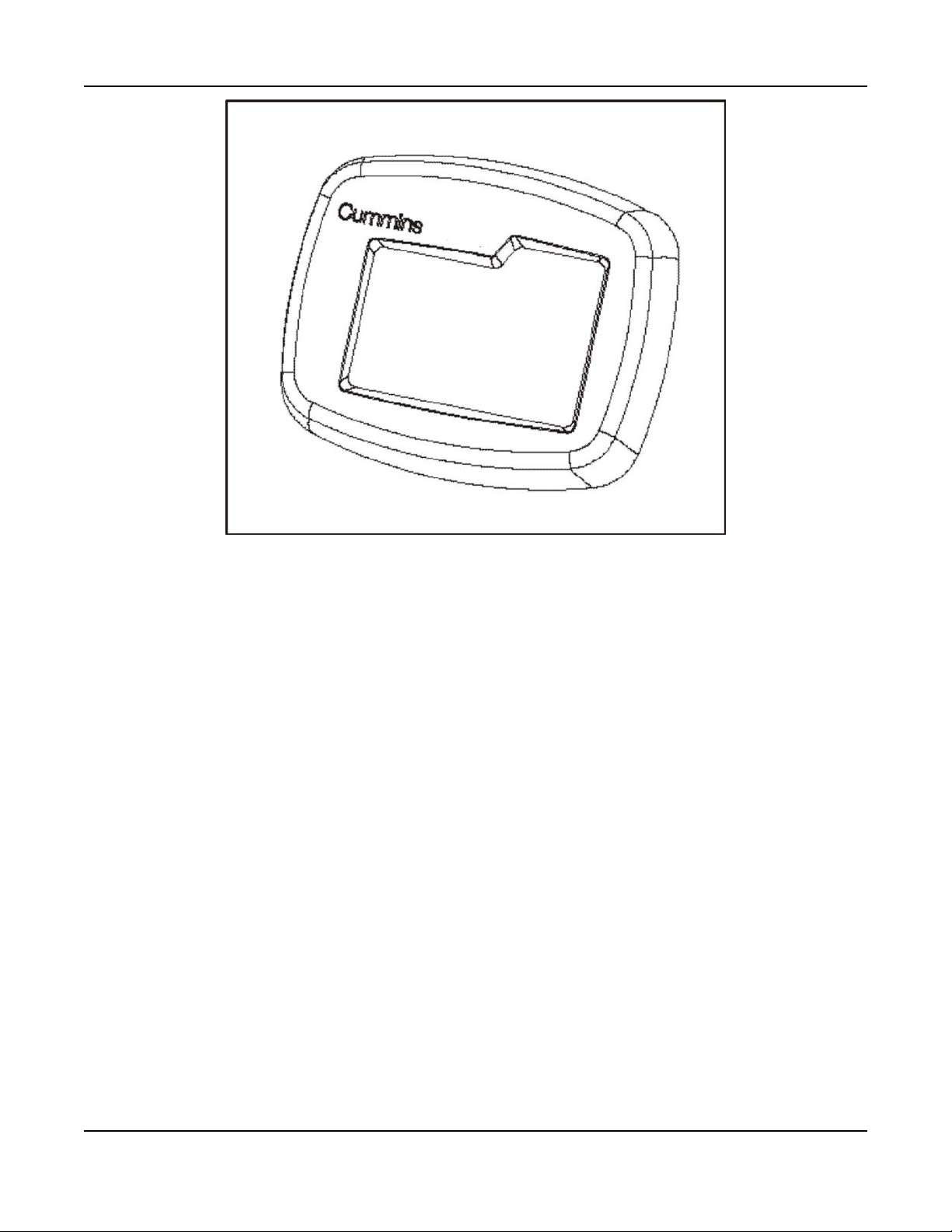
FIGURE 7. OPERATOR PANEL BEZEL
3.7.6 Load Shed Communications Wires
The control cable has the load control wires brought out of the generator set (P7-7 and P7-8). Class 1
wiring methods should be used for the in-home display, Ethernet and transfer switch communication
conductors between the generator set and transfer switch. Separation of Class 2 and power circuits
should be maintained per Article 725.136 of 2008 NFPA 70: National Electrical Code.
Use 300V 18 gauge 75 °C wire for wiring the relay.
See the following figures for the different ways the relays can be wired.
23A029V088 (Issue 22) Copyright © 2016 Cummins Inc.
Page 30
3. Step-By-Step Outline of Installation 6-2016
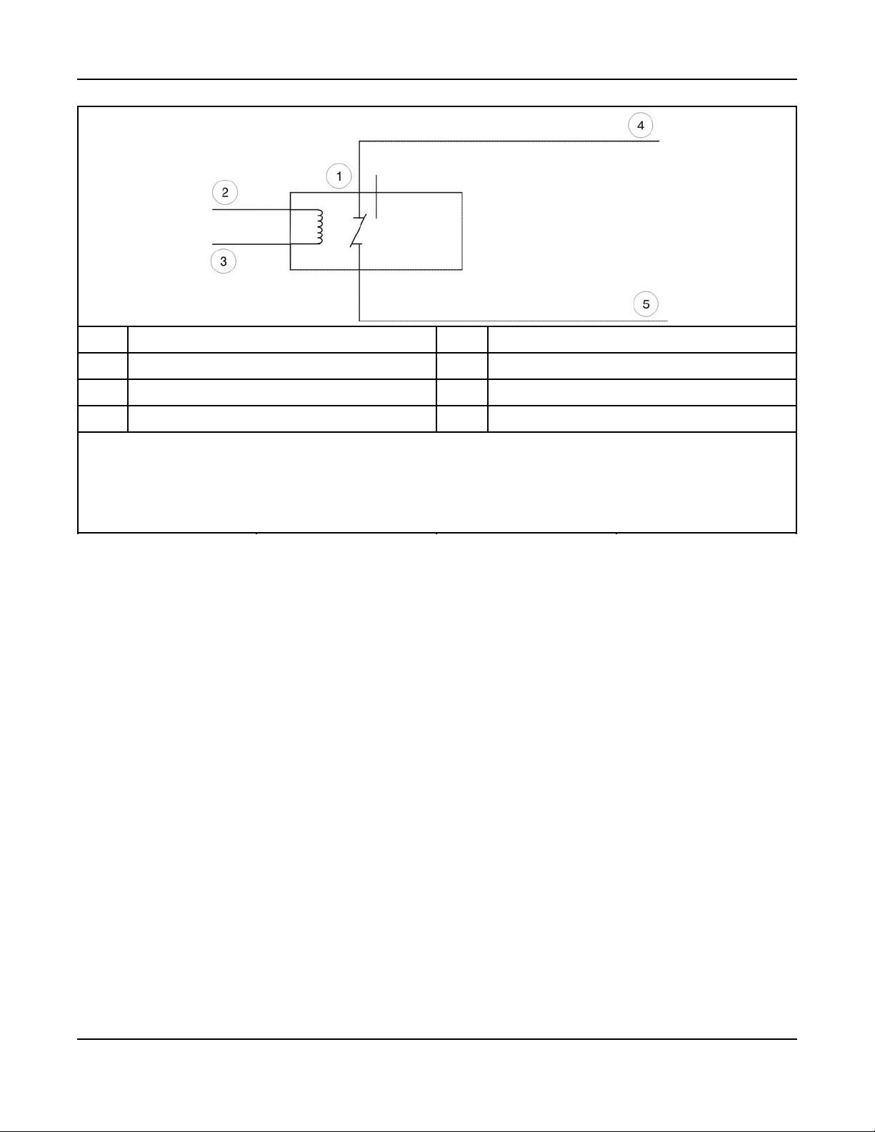
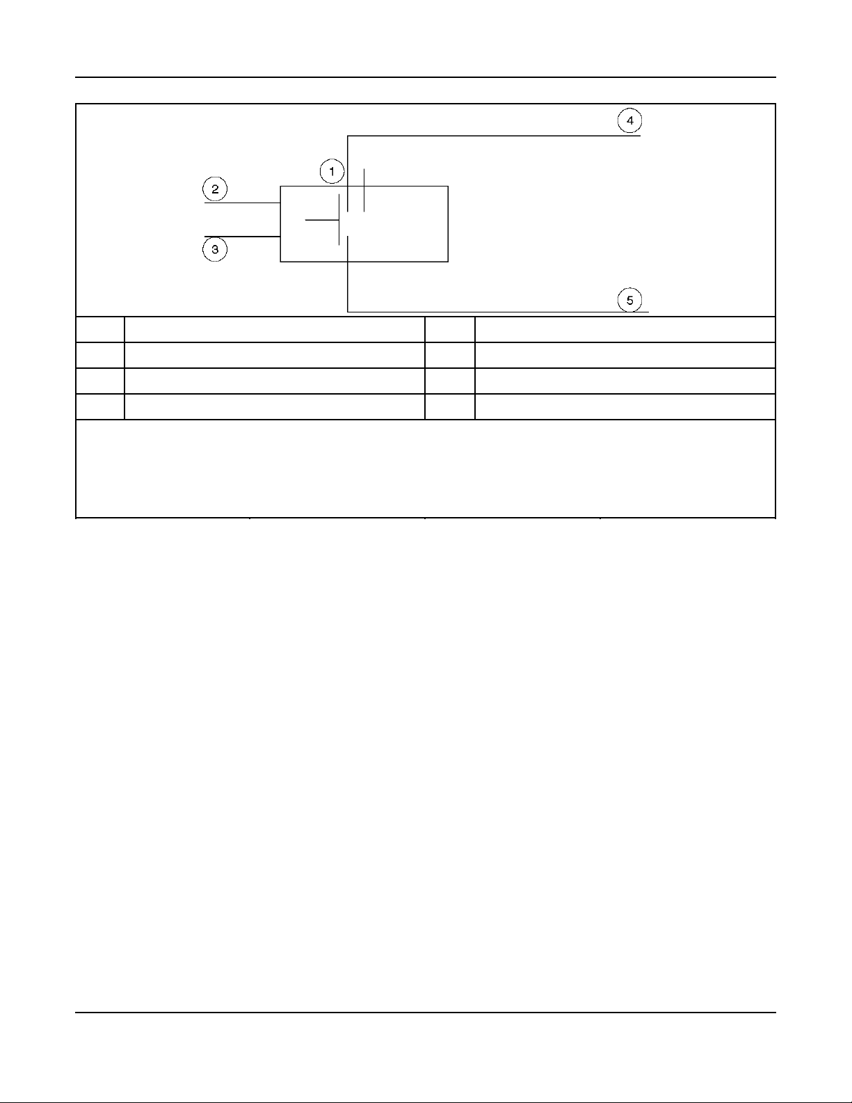
No. Description No. Description
1 Normally Closed 2 Load control pin 7 or 8
3 Ground pin 4 4 From thermostat
5 To air conditioner (load)
Relay Requirement:
• Input: 12Vdc, Max 0.5 Amp
• Contact: Low voltage current, < 40 Amp
• Mounting: No restrictions
FIGURE 8. LOW VOLTAGE RELAY SPDT
24 A029V088 (Issue 22)Copyright © 2016 Cummins Inc.
Page 31
3. Step-By-Step Outline of Installation6-2016
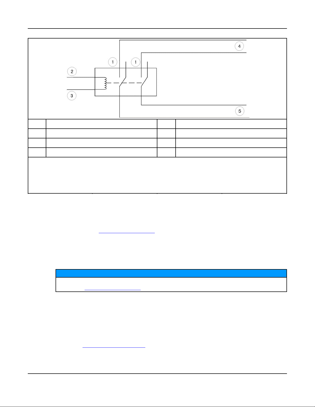
No. Description No. Description
1 Normally Closed 2 Load Control Pin 7 or 8
3 Ground Pin 4 4 From Circuit Breaker
5 To Load
Relay Requirement:
• Input: 12Vdc, Max 0.5 Amp
• Contact: 120 V AC, Amp rating for load
• Mounting: Typically in distribution panel
FIGURE 9. HIGH VOLTAGE RELAY SPDT 120V AC LOAD
25A029V088 (Issue 22) Copyright © 2016 Cummins Inc.
Page 32
3. Step-By-Step Outline of Installation 6-2016
No. Description No. Description
1 Normally Closed 2 Load Control Pin
3 Ground Pin 4 4 From Circuit Breaker
5 To Load
Relay Requirements:
• Input: 12Vdc, Max 0.5 Amp
• Contact: 120 V AC, Amp rating for load
• Mounting: Typically in distribution panel
FIGURE 10. HIGH VOLTAGE RELAY DPDT 220V AC LOAD
3.7.7 Ethernet Connections Wire
The generator set control board has a connector for Cat 5 Ethernet cable for connection to a remote
modem/router. See Ethernet/Email Interface for setup and operation.
Use Cat 5 Ethernet cable and 300V 18 gauge 75 °C wire for wiring the relay.
Class 1 wiring methods should be used for the in-home display, Ethernet and transfer switch
communication conductors between the generator set and transfer switch. Separation of Class 2 and
power circuits should be maintained per Article 725.136 of 2008 NFPA 70: National Electrical Code.
The Internet/Email interface requires “high speed" or “broadband" cable or DSL service to the
house. See Ethernet/Email Interface for a full list of requirements.
3.7.8 Battery
NOTICE
The generator set has a 12 VDC, negative-ground control and engine cranking system. The engine has a
battery charger for recharging during generator set operation.
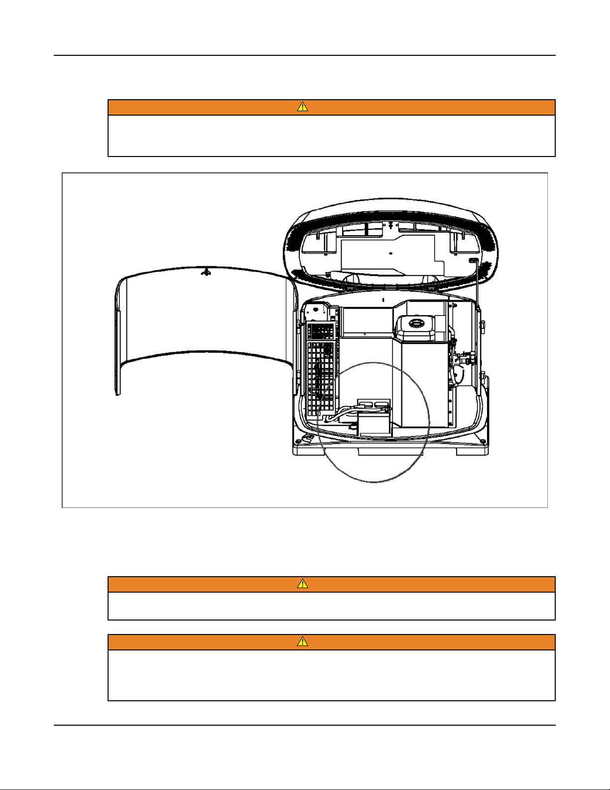
A battery charger located in the transfer switch keeps the battery charged during generator set standby.
Refer to the GSBB Specifications Table for battery specifications.
An optional thermostatically controlled battery heater is available for more reliable starting in ambient
temperatures down to -20 °F (-28.8 °C). The heater wraps around the battery. The heater cord is
connected to the 120V, accessory junction box. Install the heater in accordance with the kit instructions.
26 A029V088 (Issue 22)Copyright © 2016 Cummins Inc.
Page 33
3. Step-By-Step Outline of Installation6-2016
To prevent injury due to accidental start-up, do not connect the battery cables to the battery until the
installation has been completed and it is time to start the set.
WARNING
Before working on the generator set, move the Switch (S2) to the Stop Position, disconnect the
remote harness (P7) to disable the ATS mounted charger, and remove the negative (-) battery
cable from the battery to prevent starting.
3.8 Fuel System
Fuel systems must be installed by qualified service technicians. Improper installation presents
hazards of fire and improper operation, resulting in severe personal injury or property damage.
Gaseous fuels are flammable, explosive and can cause severe personal injury or death. Do not
smoke if you smell gas, are near fuel tanks for fuel-burning equipment or are in an area sharing
ventilation with such equipment. Keep flames, sparks, pilot lights, electrical arcs, arc-producing
equipment and all other sources of ignition well away. Keep a type ABC fire extinguisher handy.
FIGURE 11. BATTERY INSTALLATION
WARNING
WARNING
27A029V088 (Issue 22) Copyright © 2016 Cummins Inc.
Page 34

3. Step-By-Step Outline of Installation 6-2016
In all fuel system installations, cleanliness is extremely important.
• Make every effort to prevent fuel contamination of:
◦ moisture
◦ dirt
◦ excess thread sealant
◦ contaminants of any kind
• Clean all fuel system components before installing.
Gaseous-fuel supply system design, materials, components, fabrication, assembly, installation, testing,
inspection, operation and maintenance must comply with the applicable codes. See NFPA Standards No.
37, 54 and 58.
Most codes require a manual shutoff valve ahead of a flexible fuel hose. The manual valve should be of
the indicating type. The generator set has an electric (battery-powered) shutoff valve included.
NOTICE
It is recommended that a shutoff valve be located near the generator set as well, for emergency
shut off or servicing the generator set.
Until the generator set is connected, cap the fuel line stub-up at the generator set to prevent dirt from
entering and gas from discharging if the gas supply shutoff valve is opened inadvertently.
3.8.1 Fuel Line Connections
Fuel presents the hazard of fire or explosion that can result in severe personal injury or death.
Do not smoke or allow any flame, spark, pilot light or other ignition sources near fuel or in the
installation area. Read the important safety precautions in the Fuel System section of this
manual.
Refer to the Outline and System Drawings for the location of the fuel supply connection through the side
of the generator set.
The low fuel pressure switch connection comes standard on the 50 Hz. model and is an option
on the 60 Hz. model of this generator set.
A flexible fuel hose is packaged inside the generator set.
The section of flexible fuel hose supplied with the generator set must be used between the engine's fuel
system and fuel supply line to protect the fuel system from damage caused by vibration, expansion and
contraction. The fuel hose must be installed according to all applicable codes and standards.
WARNING
NOTICE
Connect it between the 3/4 NPT fitting on the generator set and the fuel supply line.
28 A029V088 (Issue 22)Copyright © 2016 Cummins Inc.
Page 35

3. Step-By-Step Outline of Installation6-2016
Callout
Number
12 Fuel Connection (Female) 3/4 NPT & NG & LPV
13 4x Anchoring Spike
Component
FIGURE 12. FUEL LINE CONNECTIONS
3.8.2 Fuel Line Connections (Model 14GSBB-6716B Only)
The factory installed, UL approved valve must be removed and an Australian Gas Association (AGA)
approved shutoff valve must be installed prior to generator set installation in Australia or New Zealand.
Adaptation from NPT to BSPT may be required, depending on the valve used. The maximum amperage of
the valve selected must be less than 1.0 amp at 12 VDC.
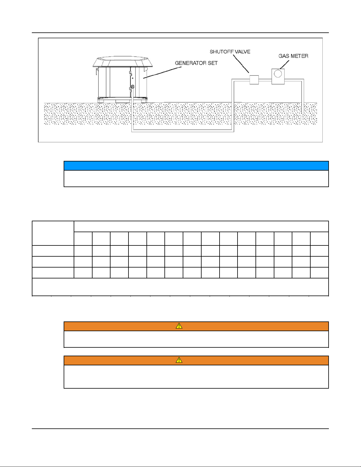
3.8.3 Natural Gas Fuel System
The generator set requires an adequate fuel supply to operate correctly at full load. The length of the fuel
supply pipe from the gas service entrance to the generator set must be known to determine the correct
fuel pipe size. Refer to the Natural Gas Pipe Capacity - Cubic Feet of Gas Per Hour table, located within
the Natural Gas Supply Line Size section of this manual to find the fuel supply requirement for your
generator set. The Pipe must be a minimum of schedule 40 subject to the authority having jurisdiction.
3.8.3.1 Natural Gas Supply
NOTICE
The Natural Gas supply meter may need to be exchanged for a higher capacity meter to supply
the additional gas consumed by the generator set.
29A029V088 (Issue 22) Copyright © 2016 Cummins Inc.
Page 36

3. Step-By-Step Outline of Installation 6-2016
See the Generator Set Specifications Table for fuel specifications, such as BTU. To determine the
required meter capacity, generator set consumption must be added to the gas consumed for heating,
cooking, clothes drying, etc.
• A typical installation might require a 400,000 BTU meter.
Consideration should also be given to utilizing high pressure gas supply (2 psi) if available. This will
reduce the required size, and therefore cost, of gas piping, especially if the location of the generator set
requires a long supply line.
NOTICE
An older site might require upgrading and repair of the gas supply system, which should be
scheduled to minimize power and gas supply interruptions.
3.8.3.2 Natural Gas Supply Line Size
See the Generator Set Specifications Table for fuel specifications (such as BTU/hr).
The Natural Gas meter may not be adequate if the meter serves other gas appliances, such as a:
• Furnace
• Water heater
• Stove
To correctly size the fuel pipe, you must also take other loads operated from the fuel supply line into
consideration, such as:
• Space heating equipment
• Water heating equipment
Use the total load requirement of the fuel supply line to determine the size of the fuel supply pipe. Use the
Natural Gas Pipe Capacity - Cubic Feet of Gas Per Hour table to determine the correct pipe size.
NOTICE
For Spec A and Canadian GSBB Spec B, make sure the fuel supply pressure at the inlet to the
generator regulator (at service port) is set between 5–11 in. WC for all operating loads (no load to
full load).
For US GSBB Spec B and Canadian GSBC Spec B, make sure the fuel supply pressure at the
inlet to the generator regulator (at service port) is set between 5–7 in. WC for all operating loads
(no load to full load).
30 A029V088 (Issue 22)Copyright © 2016 Cummins Inc.
Page 37
3. Step-By-Step Outline of Installation6-2016
FIGURE 13. TYPICAL NATURAL GAS INSTALLATION
NOTICE
Typically, 1 ft3/hr = 1000 BTU/hr. When the fuel delivery value falls between two columns, use the
larger value.
TABLE 16. NATURAL GAS PIPE CAPACITY - CUBIC FEET OF GAS PER HOUR
Normal Iron
Pipe Size
(Inches)
3/4 360 250
1 680 465 375 320 285 260 240
1 1/4 1400 950 770 660 580 530 490 460 430 400 360 325 300 280
Maximum pipe capacity in cubic feet per hour of 0.60 specific gravity Natural Gas with a pressure drop of 0.5 inches
(1.27 mm) WC over the length.
10 20 30 40 50 60 70 80 90 100 125 150 175 200
Length of Pipe in Feet
3.8.4 Propane Fuel System
WARNING
NFPA Standard No. 58 requires all persons handling and operating Propane to be trained in
proper handling and operating procedures.
WARNING
Fuel leaks can lead to explosive accumulations of gas. Propane sinks in air and can accumulate
inside housings, basements and other below-grade spaces. Prevent gas leaks and the
accumulation of gaseous fuel in the event of a leak.
31A029V088 (Issue 22) Copyright © 2016 Cummins Inc.
Page 38

3. Step-By-Step Outline of Installation 6-2016
3.8.4.1 Recommended Fuel (Propane)
WARNING
Propane presents the hazard of fire or explosion that can cause severe personal injury or death.
Do not permit any flame, spark, arc-producing equipment, switch, pilot light, cigarette or other
ignition source near the fuel system. Keep an ABC type fire extinguisher nearby.
Use clean, fresh HD-5 grade Propane or equivalent product consisting of at least 90% Propane.
NOTICE
Commercial Propane may contain more than 2.5% butane, which can result in poor fuel
vaporization and low tank pressure - resulting in poor engine staring in below 32 °F (O °C)
temperatures.
3.8.4.2 Propane Tank Size
First, some Propane tank facts to bear in mind when figuring the proper Propane tank size:
• Propane tanks are sized by the number of gallons of water they can hold, not the amount of fuel
they can hold.
• Propane tanks are generally filled to only 80% of their water capacity. Therefore, a 500 lb. tank
results in 400 lb. tank capacity.
• Low ambient temperatures affect the amount of fuel available from the Propane tank.
• Approximately 60% of the fuel (in gallons) filled in the tank can be effectively used. Therefore, a 500
lb. tank results in 300 gallon capacity.
To assist in the proper selection of the Propane tank, follow the guidelines below.
• Propane tanks must be fitted with a pressure reducing regulator before connection to the generator
set to prevent fuel system damage.
• Propane tanks must be located at least 10 ft. (3048 mm) from any source of combustion (including
the generator set).
TABLE 17. REQUIRED PROPANE TANK SIZE IN GALLONS (LITERS) FOR INDICATED TEMPERATURES
WHEN KEPT AT LEAST HALF FULL
Withdrawal
Rate
100 cfg
(250,000
BUT/hr)
[2.8 m3/hr (264
MJ/hr)]
32 °F (0 °C) 20 °F (-7 °C) 10 °F (-12
250
(945)
250
(945)
Lowest Average Winter Temperature
0 °F (-18 °C) -10 °F (-23
°C)
250
(945)
400
(1515)
°C)
500
(1890)
-20 °F (-29
°C)
1000
(3785)
-30°F (-34
°C)
1500
(5675)
150 cfg
(375,000
BUT/hr)
[4.2
m3/hr(395.6
MJ/hr)]
300
(1135)
400
(1515)
500
(1890)
32 A029V088 (Issue 22)Copyright © 2016 Cummins Inc.
500
(1890)
1000
(3785)
1500
(5675)
2500
(9640)
Page 39

3. Step-By-Step Outline of Installation6-2016
Withdrawal
Rate
200 cfg
(500,000
BUT/hr)
[5.7 m3/hr
(527.5 MJ/hr)]
300 cfg
(750,000
BUT/hr)
[8.5 m3/hr
(791.2 MJ/hr)]
32 °F (0 °C) 20 °F (-7 °C) 10 °F (-12
400
(1515)
750
(2840)
500
(1890)
1000
(3785)
Lowest Average Winter Temperature
0 °F (-18 °C) -10 °F (-23
°C)
750
(2840)
1500
(5675)
1000
(3785)
2000
(7570)
°C)
1200
(4540)
2500
(9640)
-20 °F (-29
°C)
2000
(7570)
4000
(15140)
3.8.4.3 Propane Vapor Fuel Supply Line Size and Pressure
Fuel line size depends on the amount of fuel needed to run the generator set at full load at the distance
the fuel must be moved.
• See the Generator Set Specifications Table for fuel system specifications, such as the amount of
propane vapor at certain loads.
The following figure shows a typical Propane vapor installation and the table below lists fuel capacity for
given distances and pipe size.
-30°F (-34
°C)
3500
(13250)
5000
(18925)
Size the fuel line so that the Propane vapor pressure drops no more than 1.5 inches WC from no load to
full load.
NOTICE
For Spec A and Canadian GSBB Spec B, make sure the fuel supply pressure at the inlet of the
generator fuel regulator (at service port) is set between 7–11 in. WC for all operating loads (no
load to full load).
For US GSBB Spec B and Canadian GSBC Spec B, make sure the fuel supply pressure at the
inlet of the generator fuel regulator (at service port) is set between 12–14 in. WC for all operating
loads (no load to full load).
33A029V088 (Issue 22) Copyright © 2016 Cummins Inc.
Page 40

3. Step-By-Step Outline of Installation 6-2016
TABLE 18. PROPANE VAPOR PIPE CAPACITY - CUBIC FEET OF GAS PER HOUR
Nominal Iron
Pipe Size
(Inches)
3/4 227 157 126
1 428 293 236 201 179 164 151 138 129 123 110
1 1/4 882 598 485 416 365 333 308 289 207 252 230 204
1 1/2 1323 920 743 624 567 570 472 434 409 390 346 315
2 2488 1732 1386 1197 1058 958 882 819 768 724 642 598
Maximum pipe capacity in cubic feet per hour of Propane vapor with a pressure drop of 0.5 inches (1.27 mm) WC
over the length
10 20 30 40 50 60 70 80 90 100 125 150
FIGURE 14. TYPICAL PROPANE VAPOR WITHDRAWL INSTALLATION
Length of Pipe in Feet
3.8.4.4 Converting From Natural Gas to Propane (Vapor Withdrawal)
The generator set leaves the factory set up for Natural gas.
For use with Propane, the generator must be converted by configuring the control for Propane.
For US GSBB Spec B and Canadian GSBC Spec B, additional steps must be taken when converting to
Propane.
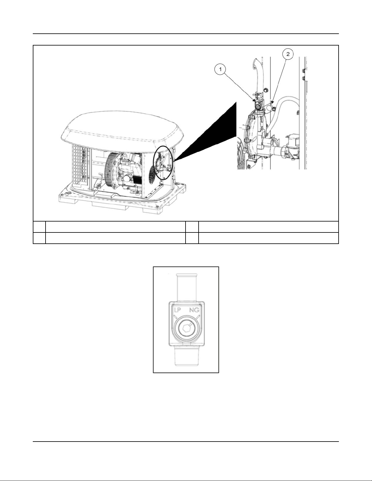
1. The manual fuel selector must be adjusted to the LP setting.
2. Once the manual fuel selection is set, install the welch plug tied to the front of the fuel regulator by
hammering the plug into the fuel selector until the plug distorts and cannot be removed. Once the
plug is installed, the fuel type cannot be changed unless the welch plug is physically removed. If the
welch plug is removed, it will most likely be damaged and will need to be replaced with a new welch
plug.
34 A029V088 (Issue 22)Copyright © 2016 Cummins Inc.
Page 41
3. Step-By-Step Outline of Installation6-2016
No. Description No. Description
1 Manual Fuel Selector 2 Welch Plug (in bag)
FIGURE 15. MANUAL FUEL SELECTOR AND WELCH PLUG (US GSBB SPEC B AND CANADIAN GSBC SPEC
B ONLY)
FIGURE 16. MANUAL FUEL SELECTOR (US GSBB SPEC B AND CANADIAN GSBC SPEC B ONLY)
35A029V088 (Issue 22) Copyright © 2016 Cummins Inc.
Page 42

3. Step-By-Step Outline of Installation 6-2016
FIGURE 17. WELCH PLUG INSTALLATION (US GSBB SPEC B AND CANADIAN GSBC SPEC B ONLY)
3.8.5 Testing the Fuel System for Leaks
WARNING
Fuel presents the hazard of explosion or fire which can result in severe personal injury or death.
Do not smoke or allow any flame, spark, pilot light, arc-producing equipment, switch or other
ignition sources around fuel or fuel components.
Before operating the generator set, test the fuel system for leaks.
• Energize the fuel solenoid from a separate 12-volt DC source before testing the fuel system
NOTICE
Testing for gas leaks with a flame can cause a fire or explosion that can lead to severe personal
injury or death. Use approved methods only.
After assembly, and before initial operation, all fuel system connections, hose valves, regulators and
fittings must be tested and proven free of leaks using a soap-and-water (or equivalent) solution while the
system is under gas or air pressure of at least 1.5 times the supply pressure or 3 psi (20.7 kPa) minimum.
• Apply the soap-and-water solution to all fuel system connections, hose valves, regulators and
fittings.
◦ When the system is running, bubbles will form where air/pressure is leaking from the system.
Other approved methods of detecting leaks can be used if appropriate. DO NOT use a flame to test for
gas leaks.
3.9 Engine Exhaust
The exhaust system for this generator set is complete and was designed specifically for this engine. Do
not modify or add to the exhaust system of this generator set.
36 A029V088 (Issue 22)Copyright © 2016 Cummins Inc.
Page 43
3. Step-By-Step Outline of Installation6-2016
WARNING
EXHAUST GAS IS DEADLY! The exhaust system must terminate away from building vents,
windows, doors and sheltered spaces that may not have ample fresh air ventilation.
WARNING
Engine discharge air and exhaust carry carbon monoxide gas (odorless and invisible) which can
cause asphyxiation and death. Never use engine discharge air or exhaust for heating a room or
enclosed space.
37A029V088 (Issue 22) Copyright © 2016 Cummins Inc.
Page 44

3. Step-By-Step Outline of Installation 6-2016
This page is intentionally blank.
38 A029V088 (Issue 22)Copyright © 2016 Cummins Inc.
Page 45

4 Optional Internet/Email Interface
Descriptions
4.1 Introduction
This feature allows for in-home or remote access to your generator set through a web page.
NOTICE
An Internet browser (i.e., Internet Explorer) is required for this option.
On this web page, you can start or stop the generator set, adjust the exerciser day and time, determine if
utility power is available and view the last 20 events/faults on the generator set.
This feature is useful for homeowners who travel or have a second home and want to be able to remotely
interface with their generator set. This feature can also help to reduce troubleshooting time and service
calls when the service technician has access to the same web page.
Use of the Ethernet is not required if you do not use web access. To set up your generator set for web
access, complete installation instructions are included in the Network Setup Guide instruction sheet,
included with your generator set literature package.
The Internet/Email Interface can make the same fault, maintenance and event notices available to you
and to your generator set service contract agency with appropriate Internet Service and email account.
NOTICE
Technical support for setup and troubleshooting of the hardware used for in-home network
access to the generator set is available through the selling Cummins Power Generation
dealer/distributor.
The owner may be required to contact their ISP and/or email provider for technical support of the
email notification feature setup and troubleshooting.
Due to the variations in network equipment, network configurations and ISPs, the owner is
responsible for acquiring the needed support/service from a qualified network specialist to
properly and securely set up the owner's network for remote monitoring of the generator set.
Cummins Power Generation does not provide technical support for setup and troubleshooting of
the owner's network and email service.
39A029V088 (Issue 22) Copyright © 2016 Cummins Inc.
Page 46

4. Optional Internet/Email Interface Descriptions 6-2016
4.2 Screen Descriptions
FIGURE 18. HOME PAGE
4.2.1 Setting Time and Date
Select the Genset Time/Date Tab on the Home Screen to set the time and date for the generator set
control.
FIGURE 19. SET GENSET TIME AND DATE
4.2.2 Set Exercise Schedule
Select the Exercise Schedule Tab on the Home Screen to set the generator set exercise schedule.
40 A029V088 (Issue 22)Copyright © 2016 Cummins Inc.
Page 47
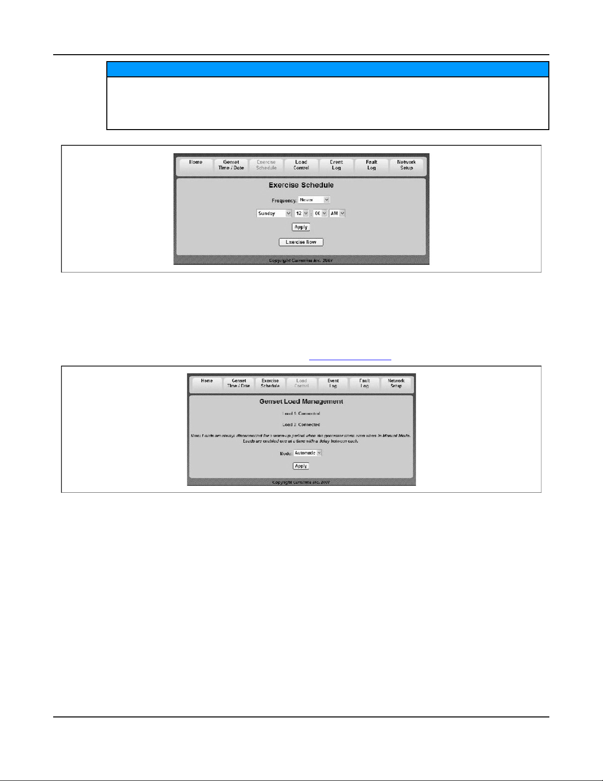
NOTICE
The generator set will exercise on the first scheduled day for which it is programmed. After that it
exercises on that day at the scheduled interval. For example, if the generator set is scheduled on
a Wednesday for Saturdays with a monthly interval, the generator set starts on the next available
Saturday. After that it exercises on Saturdays one month apart.
FIGURE 20. SET EXERCISE SCHEDULE
4.2.3 Load Control (Management)
4. Optional Internet/Email Interface Descriptions6-2016
Select the Load Control Tab on the Home Screen to enable Automatic or Manual Load Control. In
Automatic mode, the user can only view which loads are connected. In Manual mode, the user can view
loads and also connect or disconnect them. See Load Management for details.
4.2.4 Event Log
Select the Event Log Tab on the Home Screen to review the last 20 events. See the Event Log screen
capture below for a list of all of the recordable events.
FIGURE 21. GENSET LOAD MANAGEMENT
41A029V088 (Issue 22) Copyright © 2016 Cummins Inc.
Page 48

4. Optional Internet/Email Interface Descriptions 6-2016
FIGURE 22. EVENT LOG
4.2.5 Fault Log
Select the Fault Log Tab on the Home Screen to review the last 5 faults.
FIGURE 23. FAULT LOG
4.2.6 Network Setup Screen Descriptions
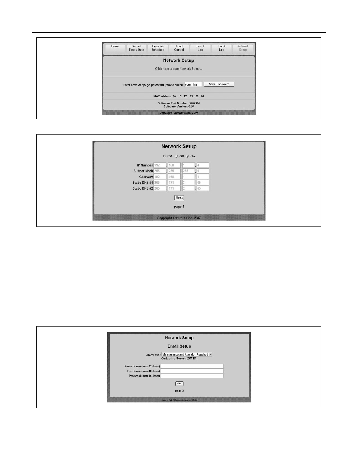
An owner-custom password can be defined in the Network Setup screen shown below. The user will be
prompted to enter the User Name and Password to access this screen.
The Network Setup Parameters screen allows dynamic addresses to be changed to static addresses. This
screen allows the user to configure the static address for the in-home network. See the Network Setup
Parameters screen shown below.
42 A029V088 (Issue 22)Copyright © 2016 Cummins Inc.
Page 49
4. Optional Internet/Email Interface Descriptions6-2016
FIGURE 24. NETWORK SETUP SCREEN
FIGURE 25. NETWORK SETUP PARAMETERS
4.2.7 Email Setup Screen Descriptions
The user must determine what events will trigger an email notification of the event:
• Never
• All Events
• Maintenance and Attention Required or Attention Required Only
This screen is also used to set up e-mail configuration.
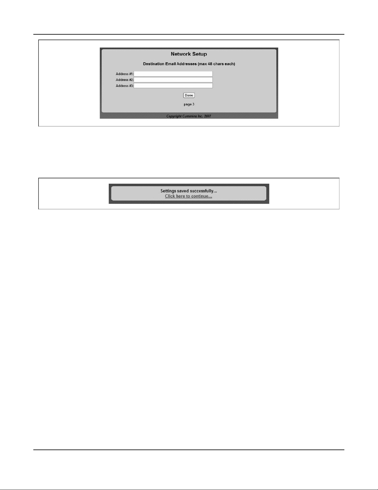
The user may enter up to three email addresses for receiving notifications of the home-standby generator
set status. See the Email Addresses figure below.
FIGURE 26. EMAIL SETUP PARAMETERS
43A029V088 (Issue 22) Copyright © 2016 Cummins Inc.
Page 50
4. Optional Internet/Email Interface Descriptions 6-2016
FIGURE 27. EMAIL ADDRESSES
4.2.8 Saving Changes
After the email addresses are added and Done is selected, this screen will appear, verifying that all
changes have been saved.
FIGURE 28. SAVE SCREEN
44 A029V088 (Issue 22)Copyright © 2016 Cummins Inc.
Page 51

5 Optional Internet/Email Interface Setup
5.1 Network Connectivity Options
Network connectivity includes in-home Network access to the generator set, e-mail notification, and
remote access to the generator set.
5.2 Material/Cable Routing
Route the category 5 Ethernet cable from the generator in the same conduit as the control lines and
display cable (for in-home mounted displays) to the transfer switch and into the house. Ensure the cable is
long enough to reach the network router. Attach the cable end connectors at each end.
5.3 Network Information Needed For Setup
The following sections will help with gathering information required for a successful installation.
5.3.1 Network Router
The following information is needed to configure the generator set with a static IP address.
• Router User Name:_______________________________
• Router Password:________________________________
• Available Static IP Address:________________________
5.3.2 Email/Internet Service Provider (ISP)
This information is used when configuring email notifications. The internet service provider (ISP) may need
to be contacted for this information.
NOTICE
If these items cannot be verified or provided, email communication and/or remote Internet access
may not work. If the service provider will not verify or provide the installer with this information,
it is the responsibility of the customer to provide this information.
Email Account Provider (May Be ISP):____________________________________________
Email Account Provider Contact Number:__________________________________________
Email Provider Allows SMTP Communications Via Port: ___
Email Provider Supports Authenticated and Unauthenticated Email: Yes/No (circle one)
NOTICE
Some email accounts will not accept unauthenticated emails and will not work with the system.
Ensure the email account and SMTP port accept non-SSL and TLS connections.
Email Server Static IP Address:_________________________________________
Email Server Name (SMTP):____________________________________________
45A029V088 (Issue 22) Copyright © 2016 Cummins Inc.
Page 52

5. Optional Internet/Email Interface Setup 6-2016
(Example: smtp.hughes.net)
Email Account User Name: _____________________________________________
(Example: [email protected])
Email Account Password:_________________________________________
Email Notification Preferences
Email Address 1:________________________________________________
Email Address 2:________________________________________________
Email Address 3:________________________________________________
NOTICE
The ISP may take several days to establish the IP address and an additional service cost may be
incurred.
5.4 In-Home Network Access to the Generator Set
1. Connect a category 5 (Ethernet) cable from the generator set control board to the modem/router.
Make sure the modem/router has sufficient ports available for connections for both the generator set
and the computer connections.
NOTICE
The router will assign an IP address to the generator set control.
2. Write down the IP Address (shown on the Network Setup screen below) on the generator set's inhome operator panel.
IP Address _____________________
46 A029V088 (Issue 22)Copyright © 2016 Cummins Inc.
Page 53

5. Optional Internet/Email Interface Setup6-2016
FIGURE 29. NETWORK SETUP SCREEN ON THE IN-HOME OPERATOR PANEL
NOTICE
Leave the DHCP (Dynamic Host Configuration Protocol) on, as it assigns a dynamic IP
address to your internet connection.
3. Type the IP address in the address bar of the web browser of a computer established on the same
in-home network as the generator set. The computer’s web browser will display the generator set’s
web page.
4. Enter the User Name and Password. The default User Name and Password is as follows.
User Name: admin
Password: cummins
5. To change your password, click the Network Setup tab. Enter a new password, and click Save
Password.
47A029V088 (Issue 22) Copyright © 2016 Cummins Inc.
Page 54

5. Optional Internet/Email Interface Setup 6-2016
FIGURE 30. GENERATOR SET HOME PAGE
FIGURE 31. NETWORK SETUP SCREEN
48 A029V088 (Issue 22)Copyright © 2016 Cummins Inc.
Page 55

5. Optional Internet/Email Interface Setup6-2016
FIGURE 32. NETWORK SETUP (PAGE 1)
5.5 Setting Up Internet Access and E-mail Alerts
1. Set up the in-home computer access to the generator set. See Section 5.4.
NOTICE
For the following steps, refer to the figures below.
FIGURE 33. NETWORK SETUP SCREEN
FIGURE 34. NETWORK SETUP PAGE 1
49A029V088 (Issue 22) Copyright © 2016 Cummins Inc.
Page 56

5. Optional Internet/Email Interface Setup 6-2016
FIGURE 35. NETWORK SETUP PAGE 2
FIGURE 36. NETWORK SETUP PAGE 3
2. Click Network Setup on the home page.
3. Click Click here to start Network Setup.
4. Click Off to turn off the generator set DHCP.
NOTICE
Skip step 5 is a unique IP address was already provided by the router.
5. In the IP Number field, enter a unique in-home network address for the generator set by changing
the field of IP address number to a number between 001 and 256 (one that is not in use by another
device on the same network).
6. The Subnet Mask, Static DNS #1 and #2, and Gateway numbers establish the connections
between the modem/router and the generator set and do not need to be changed.
7. Press Next to continue to the e-mail setup screen.
8. Select the Alert Level to choose the type of e-mail message that the customer would like to receive.
9. Enter the SMTP Port Number provided by your ISP or e-mail service provider.
10. Enter your e-mail Server Name.
NOTICE
An e-mail server name may be obtained from the customer's ISP or e-mail service provider
(example: smtp.cummins).
11. Enter the User Name and Password for the provided e-mail server.
12. Click Next to enter the destination e-mail addresses.
13. Enter up to three different e-mail addresses which will receive generator set e-mail alerts.
50 A029V088 (Issue 22)Copyright © 2016 Cummins Inc.
Page 57

5. Optional Internet/Email Interface Setup6-2016
E-mail Address 1:___________________________________________
E-mail Address 2:___________________________________________
E-mail Address 3:___________________________________________
14. Press Done to complete the e-mail confirmation.
NOTICE
If the IP address was changed in step 5, type the new address into the Internet browser's
address bar in order to return to the home screen.
15. To complete the remote viewing process, see Section 5.6 and Section 5.7.
FIGURE 37. NETWORK SETUP SCREEN
5.6 Port Forwarding
NOTICE
Opening ports in a firewall can pose network security risks. The following instructions require
forwarding port 80.
1. Access the customer’s modem/router user manual.
2. Using the operator manual, determine how to gain access to the modem/router’s setup screen.
3. Locate the port forwarding section of the modem/router’s setup menu.
4. Configure port 80 to be forwarded to the IP address created in Section 5.5.
NOTICE
To maintain connections to all devices connected to the modem/router, do not turn off the
modem/router DHCP.
5. To complete the remote viewing process, see Section 5.7.
5.7 Remote Viewing IP Options Static IP
1. Acquire a static IP address.
NOTICE
Acquiring a static IP may incur additional service charges from your ISP.
2. Use the provided static IP address to access the generator set webpage from any location with
Internet access.
51A029V088 (Issue 22) Copyright © 2016 Cummins Inc.
Page 58

5. Optional Internet/Email Interface Setup 6-2016
5.8 Dynamic IP Monitoring
NOTICE
If a static IP address has been authorized from your ISP, the following steps are not required.
Some services may require software to be installed on a home computer.
1. Determine the home network's public/external IP address using an online tool (such as,
www.whatismyip.com).
2. Locate a dynamic IP host online and register for services.
NOTICE
Online dynamic hosting service can often be provided at no cost.
3. Configure the modem/router to update the dynamic IP host each time its external/public IP address
changes.
NOTICE
Instructions for completing the above step should be provided by the dynamic IP
monitoring host and the router user manual.
4. Use the URL provided by the dynamic IP host service to access the generator set webpage from any
location with Internet access.
5.9 Help Hotline
1-800-888-6626 option 1
Technical support for setup and troubleshooting of the hardware used for in-home network access to the
generator set is available through the selling Cummins Power Generation dealer/distributor.
The owner may be required to contact their ISP and/or email provider for technical support of the e-mail
notification feature setup and troubleshooting.
Due to the variations in network equipment, network configurations and ISPs, the owner is responsible for
acquiring the needed support/service from a qualified network specialist to properly and securely set up
the owner's network for remote monitoring of the generator set.
Cummins Power Generation does not provide technical support for setup and troubleshooting of the
owner's network and email service.
• If you can't remember your password, reset it to “cummins" by selecting Reset Password on the
Network Setup screen on the in-home Operator Panel and pressing the up or down arrow.
• The customer's public IP Address must be a static IP Address. If the customer's public IP Address is
dynamic, the customer must either obtain a static IP Address from their service provider or set up a
domain name that manages the dynamic IP Address.
5.10 Frequently Asked Questions
Question: Do I need a router?
52 A029V088 (Issue 22)Copyright © 2016 Cummins Inc.
Page 59

5. Optional Internet/Email Interface Setup6-2016
Answer: Yes, a router or switch is required to allow for the connection of more than one device
(computer, generator set, etc.) with each other and the Internet.
• Typically, your Internet modem also serves as a router.
• If you have an available Ethernet connection on your router-enabled modem, you may not need to
add an additional router.
Question: Do I need a modem?
Answer: A modem is required if you want to utilize the email and remote Internet access features of the
generator set.
• Only one modem is required.
• If you already have an Internet connection, you have a modem.
Question: What is an IP Address?
Answer: An IP Address, or Internet Protocol Address, is a unique address that devices such as a
computer or your home generator set use to communicate with each other, both on your in-home network
(LAN network) or with the World Wide Web.
Question: What is the difference between Static and Dynamic IP Addresses?
Answer:
Dynamic IP Address - On your in-home network, the router (with DHCP enabled) will assign a dynamic IP
Address to all devices (computer, home generator set, etc.) connected to the router. As devices are added
and removed from the router, the devices are automatically updated with new IP Addresses. This means
that your computer and generator set IP Addresses will not always be the same unless static IP
Addresses are assigned.
Static IP Address - A static IP Address is a unique address that is permanently assigned to a device. On
the World Wide Web, your typical ISP (Internet Service Provider) assigns a dynamic IP Address to your
Internet connection. This is the IP Address you type into your Internet browser to access your generator
set from the World Wide Web. A static IP Address is required for you to establish a constant address you
can always access from the World Wide Web. Contact your ISP to set up a static IP Address for your
Internet connection.
Question: What is DHCP?
Answer: DCHP, or Dynamic Host Configuration Protocol, automatically assigns IP Addresses, subnet
masks, and gateways to devices, allowing them to communicate with each other.
• Your router and generator set are equipped with DHCP.
• Default is for DHCP to be on.
Question: What is a UPS device and why is it recommended?
Answer: A UPS (Uninterruptible Power Supply) device is battery backup to keep devices such as
computers and modems powered during short-term power outages.
• We recommend that the modem/router be powered through a UPS device to ensure that your
generator set is able to send emails and be remotely accessed at all times.
◦ For example, if your generator set shuts down during a utility power outage, the generator set
can still send you an email letting you know that the power has failed and that the generator
set shut down.
Question: When do I need to use a Static IP Address?
Answer: Static IP addresses are required if you plan to access your generator set remotely via the
Internet.
Question: I used the IP Addresses shown on the front of this guide, but why was I not able to access the
generator set?
53A029V088 (Issue 22) Copyright © 2016 Cummins Inc.
Page 60

5. Optional Internet/Email Interface Setup 6-2016
Answer: The IP Addresses shown in this guide are only examples and are not likely to be the ones that
will work on your network setup.
Question: The IP Address consists of four numbers ranging from 0 to 255 which are separated by dots;
179.168.052.094, for example. Are leading zeros necessary?
Answer: No, the IP Address, 192.168.0.1, for example, is equivalent to 192.168.000.001. The address
can be entered either way.
Question: How do I get my IP Number, Subnet Mask and Gateway?
Answer:
On a PC:
1. Disable the PC's wireless function.
2. Establish an Ethernet connection between the computer and generator set via a common modem.
3. On the computer, Click Start>Run.
4. On the run menu that appears type “cmd" and click OK.
5. Type “ipconfig" on the DOS window that appears.
Question: Why do I need two IP Addresses to access my generator set?
Answer: You can access your generator set from two networks, your in-home or local network, and from
the World Wide Web, thus requiring two addresses.
• Your local IP Address is different from your World Wide Web IP Address.
◦ From your in-home network you use the generator set's Static IP Address.
◦ From the World Wide Web you first need to access your modem, which is accomplished by
typing in the Static IP Address of your Internet connection.
Your modem will then automatically forward you to your generator set on the local network.
54 A029V088 (Issue 22)Copyright © 2016 Cummins Inc.
Page 61

6 Operation
6.1 3 Position Switch
A three-position Start/Stop switch is located at the genset control panel.
Switch positions available:
• Manual Start: Normally only the maintenance/service technician has occasion to manually start and
stop the generator set. Push the switch down at the thick end to start the set immediately.
• Stop (middle position): This switch disables the set.
• Remote: For automatic operation, the Start/Stop switch must be in the Remote position and Standby
On must be activated on the In-Home Display. Push the switch down at the thin end to put into the
Remote position.
No. Description No. Description
1 Manual Start Position 2 Remote Position
3 Stop Position
FIGURE 38. 3 POSITION SWITCH (STOP SWITCH)
6.2 In-Home Operator Panel
The operator panel must be hard-wired to the generator set in order for the generator system to operate.
55A029V088 (Issue 22) Copyright © 2016 Cummins Inc.
Page 62

6. Operation 6-2016
NOTICE
The in-home operator panel and Internet/Email interface can be used simultaneously
The operator panel consists of two UTILITY status lamps, three GENERATOR status lamps, three action
buttons and an LCD display screen with four navigation buttons.
No. Description
1 Back Button - When navigating through the LCD menus, press this button to return to the main operating
screen.
2 Standby On/Off Button - See the To Enable/Disable Standby section of this manual.
3 Start Stop Button - See the To Manually Start/Stop Generator Set section of this manual.
4 Navigation Buttons - The function of these buttons change as different screens appear.
FIGURE 39. IN-HOME OPERATOR PANEL
6.2.1 BACK Button
When navigating through the LCD menus, press the BACK button to return to the main operating screen.
6.2.2 START STOP Button
See To Manually Start/Stop Generator Set.
6.2.3 Standby ON/OFF Button
See To Enable/Disable Standby.
56 A029V088 (Issue 22)Copyright © 2016 Cummins Inc.
Page 63
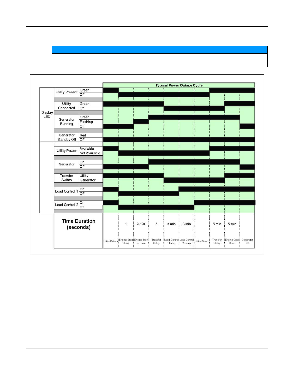
6.3 Typical Operation
The following diagrams are based on an APPROXIMATE time duration. Your genset may vary
slightly from the timing diagrams in this manual.
6. Operation6-2016
NOTICE
FIGURE 40. TYPICAL POWER OUTAGE CYCLE TIMING DIAGRAM
57A029V088 (Issue 22) Copyright © 2016 Cummins Inc.
Page 64
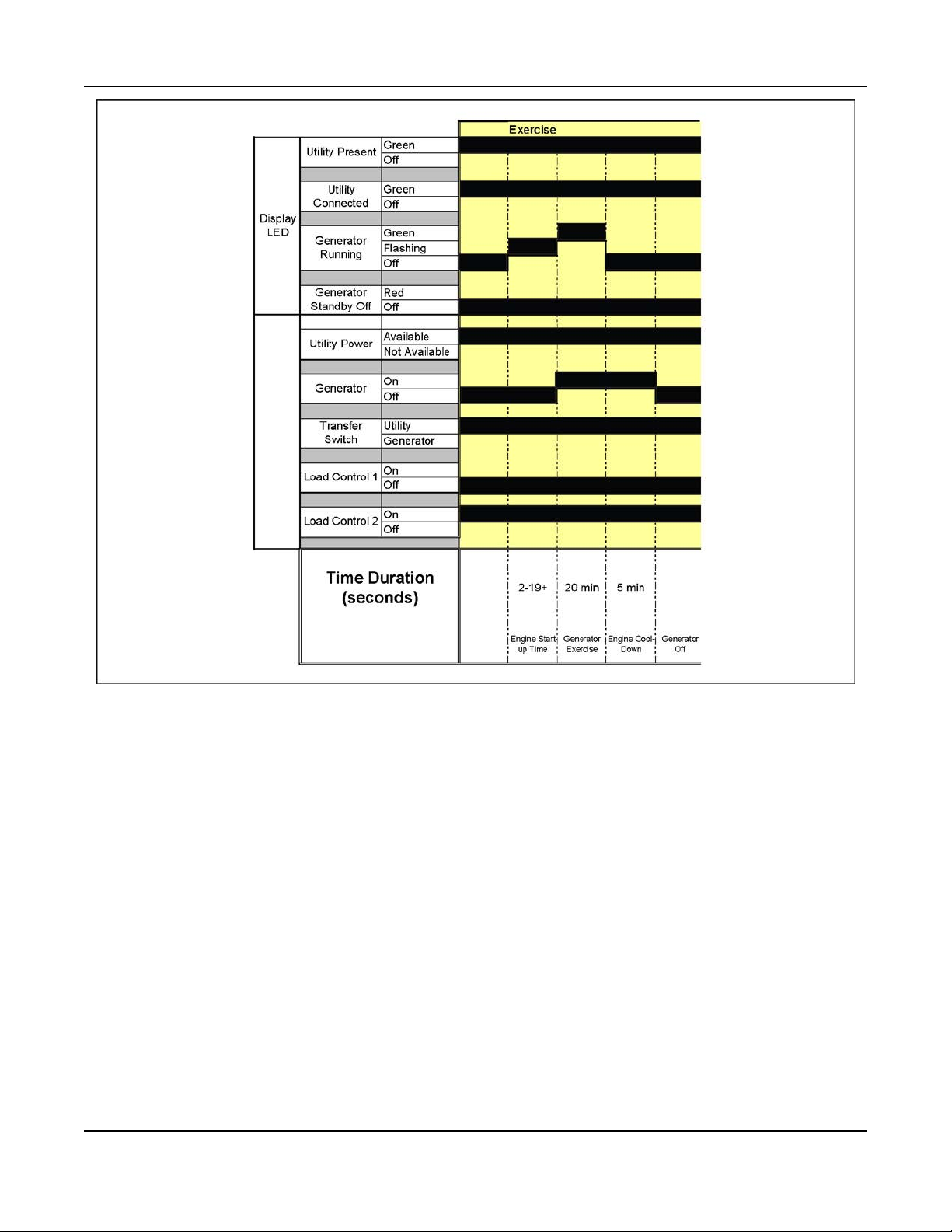
6. Operation 6-2016
FIGURE 41. EXERCISE TIMING DIAGRAM
58 A029V088 (Issue 22)Copyright © 2016 Cummins Inc.
Page 65

6. Operation6-2016
FIGURE 42. MANUAL START/STOP TIMING DIAGRAM
59A029V088 (Issue 22) Copyright © 2016 Cummins Inc.
Page 66

6. Operation 6-2016
FIGURE 43. LOAD MANAGEMENT TIMING DIAGRAM
6.3.1 Normal Operation: Utility Power Available and Connected
As long as utility power is available and connected, both of the green UTILITY lamps (PRESENT and
CONNECTED) will stay on and the LCD screen will indicate “Genset Stopped".
If the red GENERATOR STANDBY OFF light is on, the generator set will not start up automatically if utility
power is interrupted. See the To Enable/Disable Standby section of this manual to enable STANDBY so
that the generator set will automatically supply power if utility power is interrupted.
60 A029V088 (Issue 22)Copyright © 2016 Cummins Inc.
Page 67
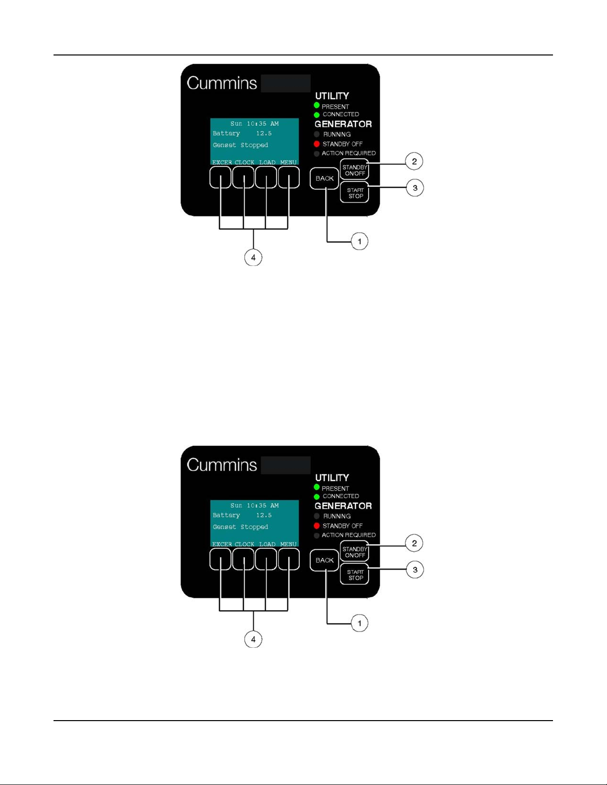
FIGURE 44. UTILITY PRESENT AND CONNECTED—STANDBY OFF LAMP ON
6.3.2 Emergency Operation: Utility Power Interrupted
6. Operation6-2016
If utility power is interrupted,
1. The green UTILITY PRESENT lamp will go out
2. The generator set will start automatically and the green GENERATOR RUNNING lamp will turn on.
3. The UTILITY CONNECTED light will go out when the generator set is connected to supply power.
The LCD screen will provide a visual indication of “Genset Load" (bar graphs). The bar graphs indicate
how much of the available power is being used in each supply line (L1 and L2).
If the red ACTION REQUIRED light comes on, either the generator shut down or periodic maintenance
has come due. The LCD screen will indicate what maintenance is due or which fault occurred.
FIGURE 45. GENERATOR SET RUNNING—ACTION REQUIRED LAMP ON
61A029V088 (Issue 22) Copyright © 2016 Cummins Inc.
Page 68
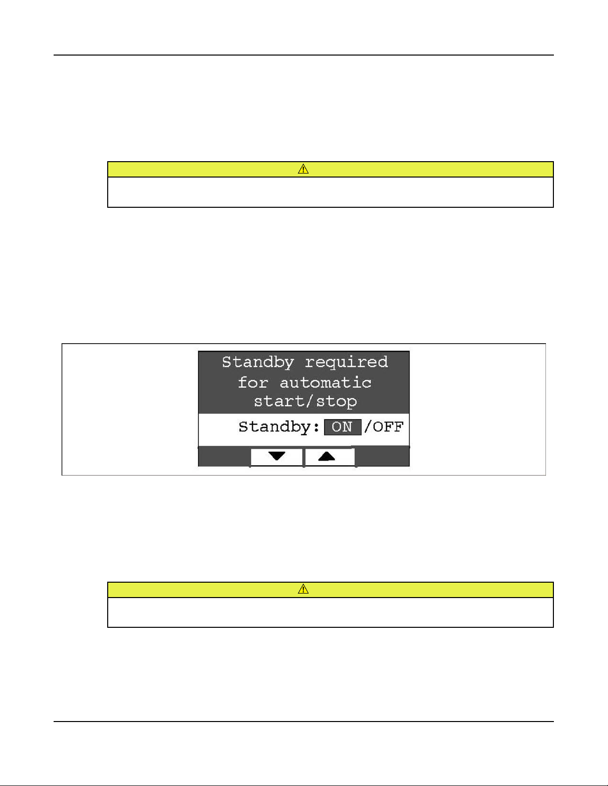
6. Operation 6-2016
6.4 To Enable/Disable Standby
Normally, you should not have to disable generator set STANDBY.
• STANDBY should always be enabled (ON) except during maintenance/service.
• STANDBY will have to be re-enabled (STANDBY OFF light on) if the generator set is started or
stopped manually (normally a maintenance/service function) or a fault shutdown has occurred.
CAUTION
When STANDBY is disabled the generator set will NOT automatically start to supply power if
utility power is interrupted.
To enable or disable generator set standby:
1. Press the STANDBY ON/OFF button on the operator panel, which takes you to the Standby ON/OFF
screen.
2. Press the up or down arrow button to select ON or OFF.
3. To enable STANDBY select ON and press the BACK button. The STANDBY OFF lamp will go out
and the display will state: “Standby ready enabled by user."
4. To disable STANDBY select OFF and press the BACK button. The STANDBY OFF lamp will come
on and the display will state: “Standby ready disabled by user."
FIGURE 46. ENABLE/DISABLE STANDBY SCREEN
6.5 To Manually Start/Stop Generator Set
Normally, only the maintenance/service technician has to manually start and stop the generator set.
• Starting the generator set will result in the generator powering the house loads.
CAUTION
Manually starting or stopping the generator set disables generator set STANDBY. The generator
set will not automatically start to supply power if utility power is interrupted.
Manually start and stop the generator set once every 3 months to test that these functions are
working properly.
62 A029V088 (Issue 22)Copyright © 2016 Cummins Inc.
Page 69
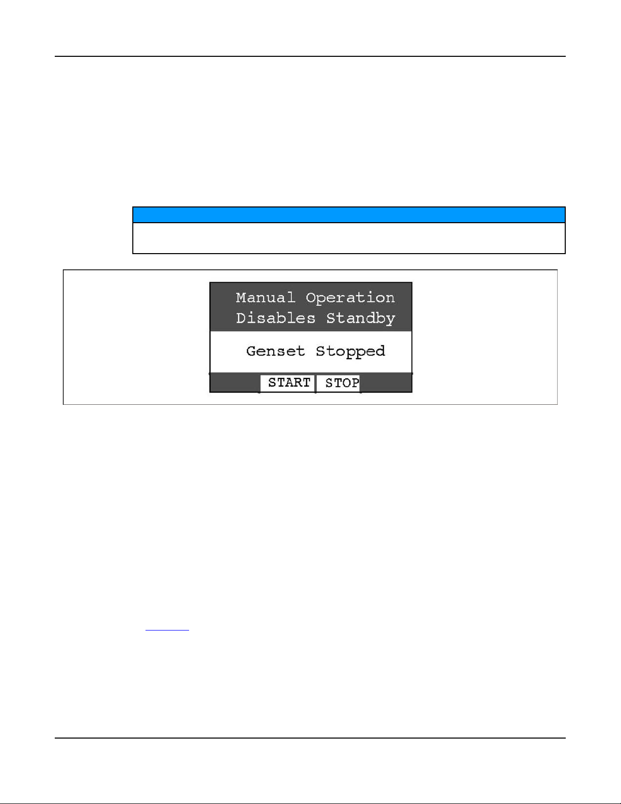
6. Operation6-2016
To manually start or stop the generator set:
1. Press the START STOP button on the operator panel, which takes you to the Genset START/STOP
screen.
• The screen will display “Genset Stopped" or “Genset Running," as appropriate.
2. Press START to manually start the generator set and connect it to supply power to the house. The
STANDBY OFF lamp will come on and the display will state: “Genset started manually (Standby
Ready Disabled)."
3. Press STOP to manually stop the generator set and disconnect it. The STANDBY OFF lamp will
come on and the display will state: “Genset stopped manually (Standby Ready Disabled)."
NOTICE
To start the generator set without connecting loads pick Exercise Now on the Exerciser
Clock screen.
FIGURE 47. GENSET START/STOP SCREEN
6.6 Fault, Maintenance and New Event Screens
Various warning and event screens may appear on the operator panel during Normal or Emergency
Operation.
6.6.1 Fault Screen
If a generator set shutdown fault occurs, a FAULT warning appears with the following information:
• Brief description of the warning or fault
• The two-digit Fault Code Number
• The time of occurrence of the fault
Press the BACK button to reset the fault and return to the home screen.
See the Fault Log section of this manual to review the log of the last 5 faults.
63A029V088 (Issue 22) Copyright © 2016 Cummins Inc.
Page 70
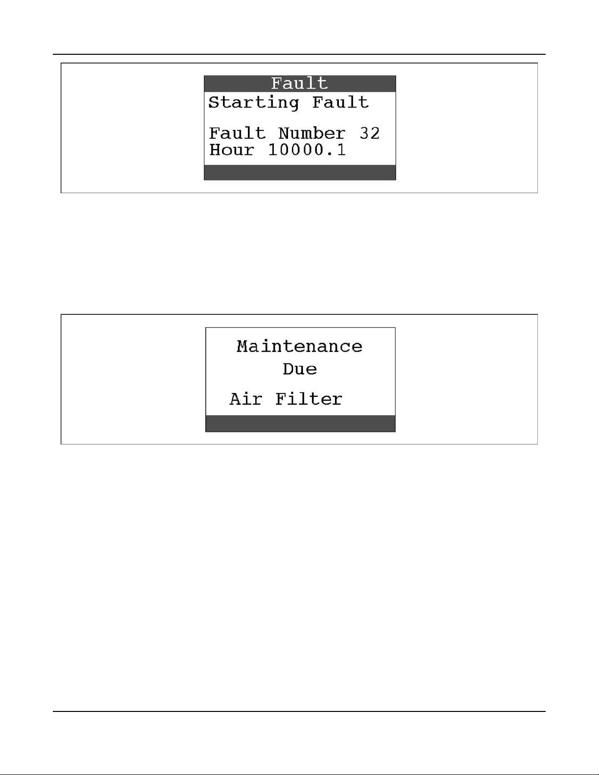
6. Operation 6-2016
FIGURE 48. TYPICAL FAULT SCREEN
6.6.2 Maintenance Due Screen
A Maintenance Due screen appears when a scheduled maintenance operation is due.
• The warning does not time out.
• Perform the maintenance.
Press the BACK button to return to the home screen.
FIGURE 49. TYPICAL MAINTENANCE DUE SCREEN
6.6.3 New Event Screen
A New Event screen appears whenever system status changes, such as when there is an interruption of
utility power. The screen provides a brief description of the event along with the time and date of the
event.
• The message does not time out, unless superseded by a new event.
• Press the BACK button to return to the home screen.
64 A029V088 (Issue 22)Copyright © 2016 Cummins Inc.
Page 71
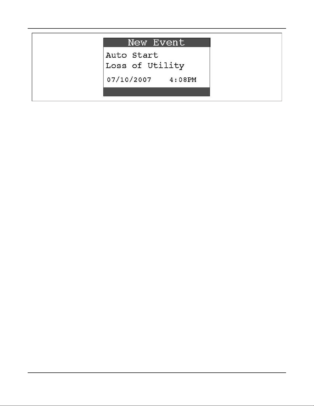
FIGURE 50. TYPICAL NEW EVENT SCREEN
6.7 Genset Status
To check generator set output voltage and frequency and the total numbers of hours run:
1. Press the MENU button on the home screen.
2. Press the up or down arrow button on the menu screen to select Genset Status.
3. Press the ENTER button on the menu screen and note the values displayed on the Genset Status
screen.
6. Operation6-2016
4. Press the BACK button to return to the home screen.
65A029V088 (Issue 22) Copyright © 2016 Cummins Inc.
Page 72
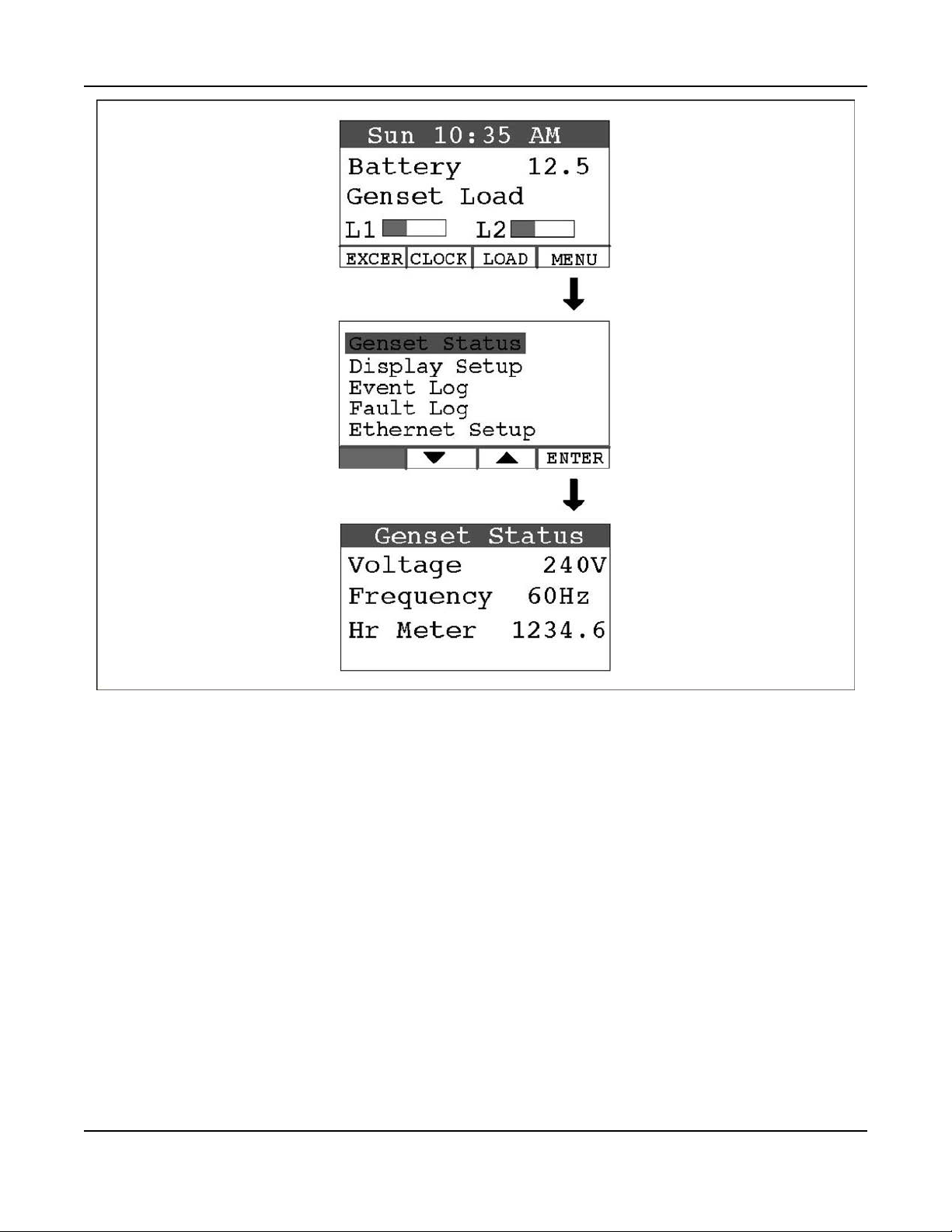
6. Operation 6-2016
FIGURE 51. GENERATOR SET STATUS SCREEN
6.8 Display Setup and Software Info
6.8.1 Brightness and Contrast
To change the Brightness and Contrast of the display screen:
1. Press the MENU button on the home screen.
2. Press the up or down arrow button on the menu screen to select Display Setup.
3. Press the ENTER button on the menu screen.
4. Press the NEXT button to select Brightness or Contrast.
5. Press the increase or decrease arrow button to increase or decrease brightness.
6. Change Contrast the same way as Brightness.
7. Press the BACK button to save the settings and return to the home screen.
66 A029V088 (Issue 22)Copyright © 2016 Cummins Inc.
Page 73
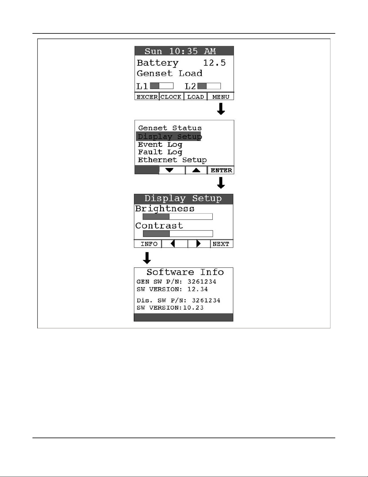
6. Operation6-2016
FIGURE 52. DISPLAY SETUP AND SOFTWARE INFO SCREENS
6.8.2 Software Info
To check on the generator set and display software:
1. Press the MENU button on the home screen.
2. Press the up or down arrow button on the menu screen to select Display Setup.
3. Press the ENTER button on the menu screen.
4. Press the INFO button on the Display Setup screen and note the values displayed on the Software
Info screen.
5. Press the BACK button to return to the home screen.
67A029V088 (Issue 22) Copyright © 2016 Cummins Inc.
Page 74

6. Operation 6-2016
6.9 Event Log
6.9.1 To Check Log of Last 20 Events
1. Press the MENU button on the home screen.
2. Press the up or down arrow button on the menu screen to select Event Log.
3. Press the ENTER button on the menu screen.
4. Scroll through the event log with the up and down double-arrow buttons. Each screen provides a
brief description of the event along with the time and date of the event.
5. Press the BACK button to return to the home screen.
FIGURE 53. EVENT LOG SCREEN
6.9.2 List of Recordable Events
• "Genset started manually (Standby Ready Disabled)"
• "Genset stopped manually (Standby Ready Disabled)"
• "Genset exercise started"
• "Genset exercise completed"
• "Genset started due to loss of utility"
• "Genset stopped with return of utility"
68 A029V088 (Issue 22)Copyright © 2016 Cummins Inc.
Page 75

• "Switch on genset moved to remote position"
• "Switch on genset moved to run position"
• "Switch on genset moved to off position"
• "Standby ready disabled by user"
• "Standby ready enabled by user"
• "Utility lost - not in Standby Ready"
• "Utility returned - not in Standby Ready"
• "Maintenance reminder - Change oil and check valve lash"
• "Maintenance reminder - Change oil & filter, air filter, adjust valve lash, clean and check battery &
engine cooling fins"
• "Genset fault - (Fault description appended)"
• "Genset warning - Transfer Switch Signal Failure"
• "Genset warning - Transfer Switch Failed to Transfer to Utility"
• "Genset warning - Low Battery or Battery Charger Failure"
6.10 Fault Log
6. Operation6-2016
To check the log of the last 5 faults:
1. Press the MENU button on the home screen.
2. Press the up or down arrow button on the menu screen to select Fault Log.
3. Press the ENTER button on the menu screen.
4. Scroll through the fault log with the up and down double-arrow buttons. Each screen provides a brief
description of the fault, the fault code number and the time and date of the fault.
5. Press the BACK button to return to the home screen
NOTICE
If there are no faults recorded, the “No Stored Faults" screen will appear.
69A029V088 (Issue 22) Copyright © 2016 Cummins Inc.
Page 76
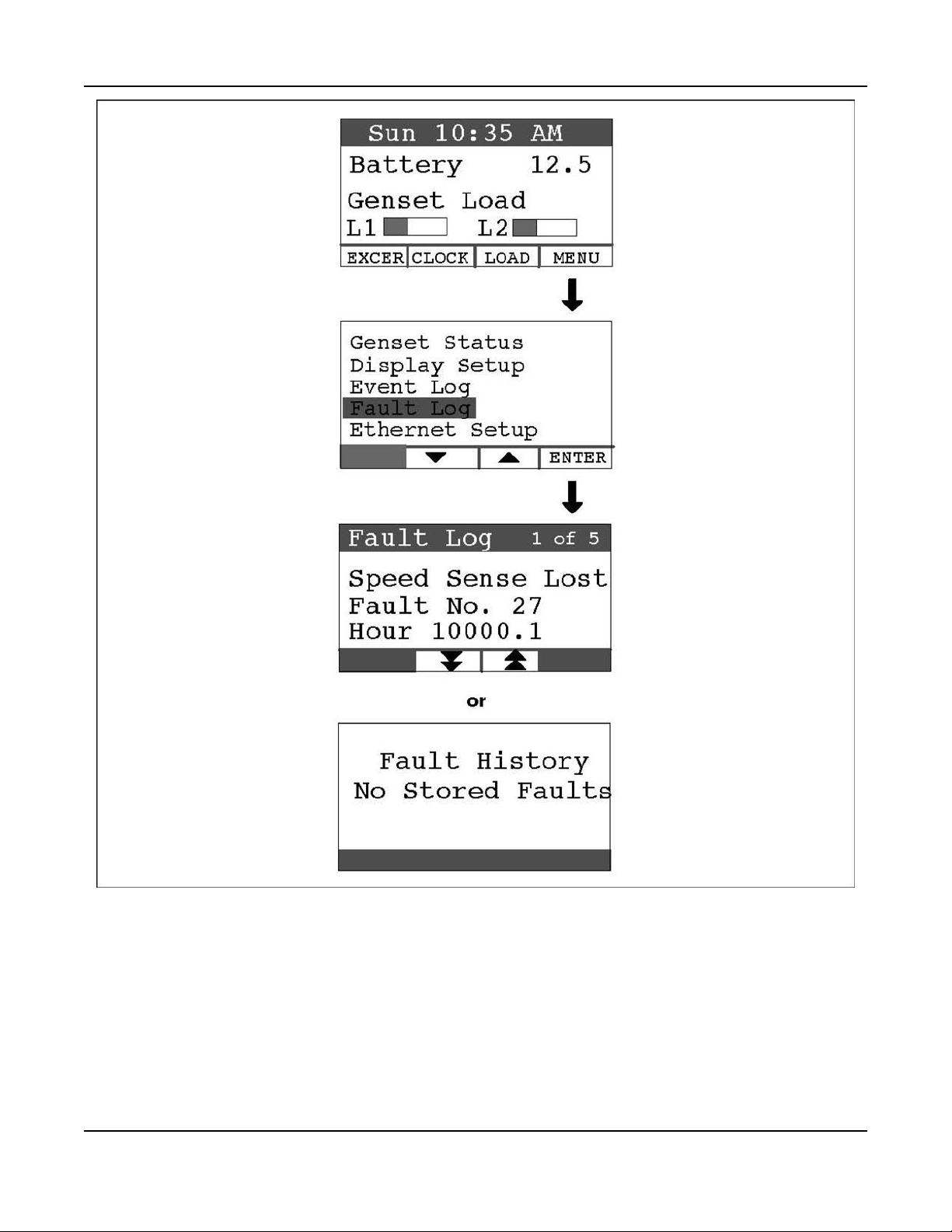
6. Operation 6-2016
FIGURE 54. FAULT LOG SCREEN
6.11 Exercise Settings
To set the generator set exercise schedule:
1. Press the EXCER button on the home screen.
2. Press the NEXT button on the Exerciser Clock screen to select the field to change.
3. Press the up or down arrow button to increase or decrease the frequency of exercise and the day of
the week and time of day for exercise.
70 A029V088 (Issue 22)Copyright © 2016 Cummins Inc.
Page 77
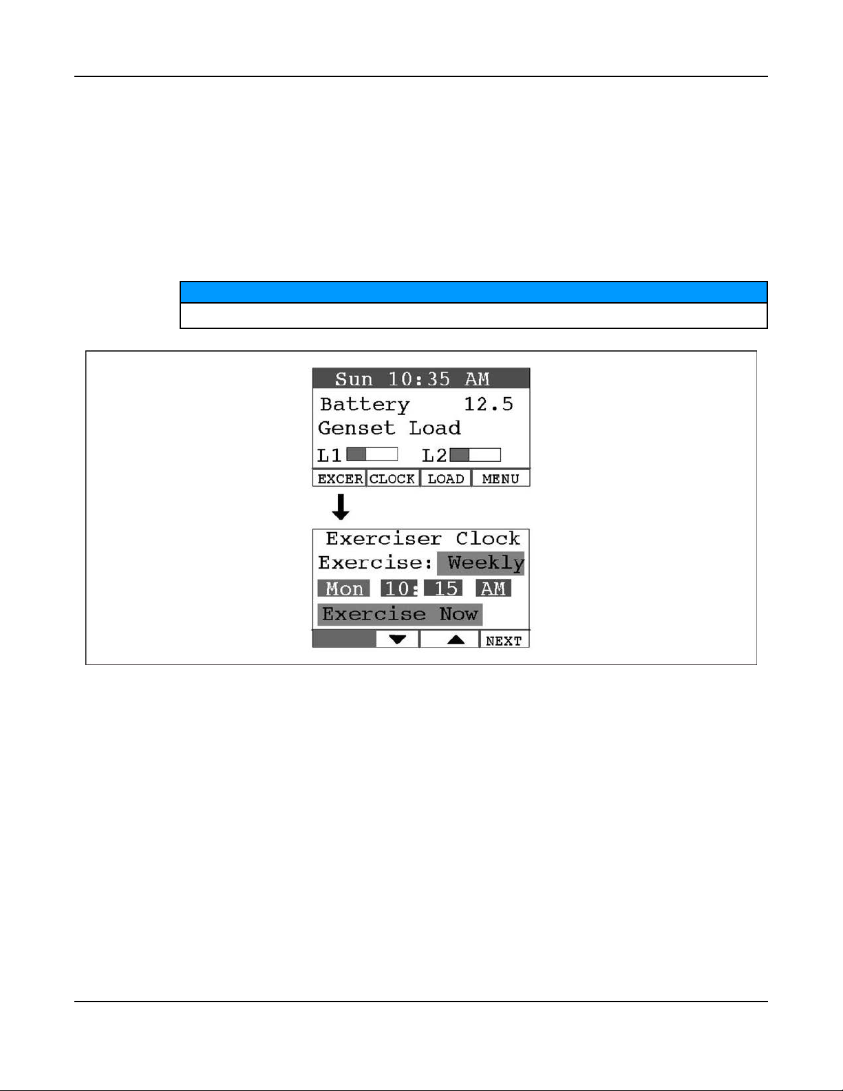
6. Operation6-2016
Frequency selections are:
Weekly
Bimonthly
Monthly
Never
4. Press the BACK button to save the settings and return to the home screen.
5. If you want to exercise the generator set now, select Exercise Now, and press either the up or down
arrow.
NOTICE
Scheduled or prompted exercise does not transfer the house loads to the generator set.
6.12 Time Setup
To set up the generator set clock for the current date and time:
1. Press the CLOCK button on the home screen.
2. Press the NEXT button on the Time Setup screen to select the field to change.
3. Press the up or down arrow button to increase or decrease or change the date or time.
4. Press the BACK button to save the settings and return to the home screen.
FIGURE 55. EXERCISE CLOCK SCREEN
71A029V088 (Issue 22) Copyright © 2016 Cummins Inc.
Page 78
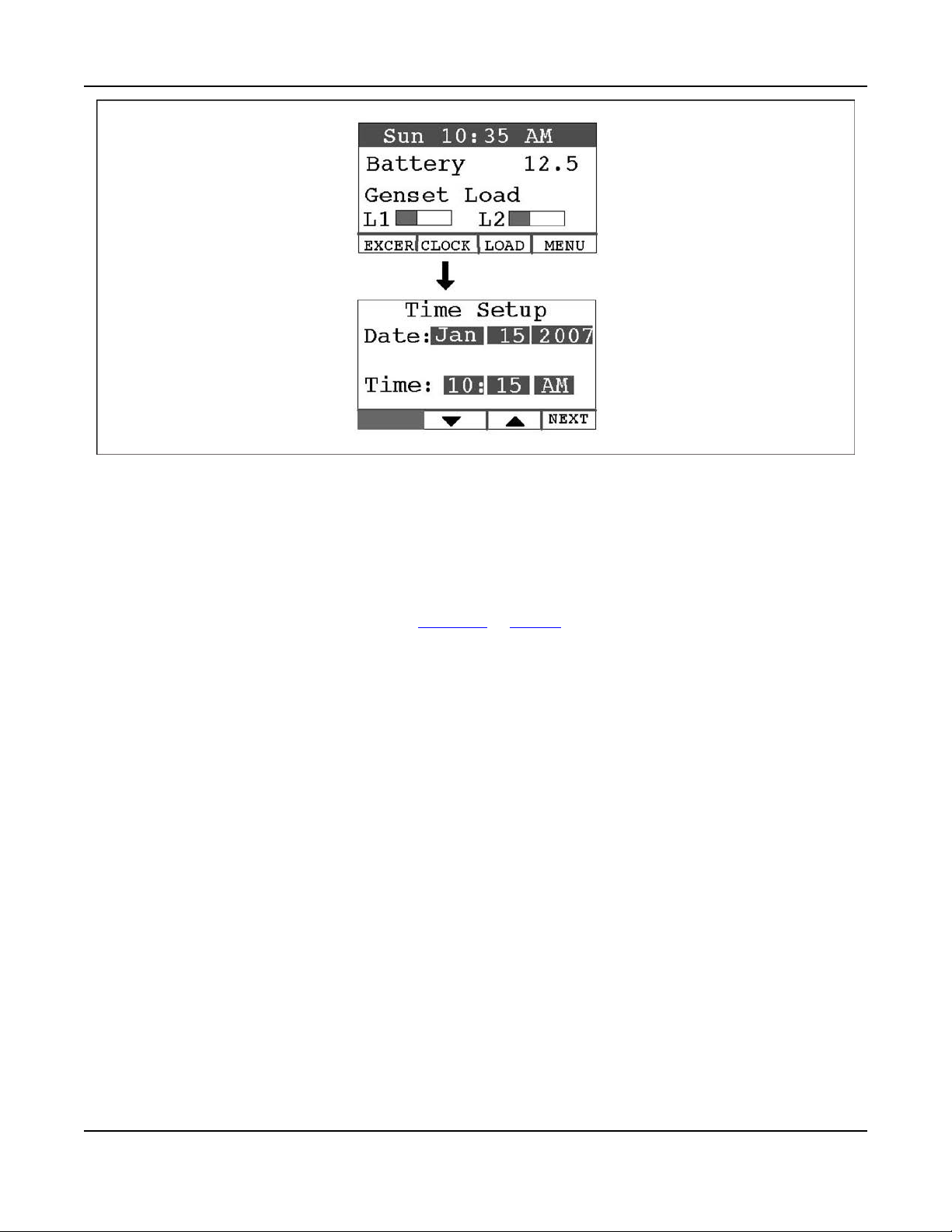
6. Operation 6-2016
FIGURE 56. TIME SETUP SCREEN
6.13 Load Management
The generator set may have been set up at installation to connect and disconnect certain large loads,
such as air conditioners, to manage the total load so as not to overload the generator set. This requires
the installation of relays to the load management signals which allow for the disconnection of loads. Load
management can be set to operate in automatic or manual mode.
Whether in automatic or manual mode, there is a delayed start. Load 1 is enabled three minutes after the
generator set is connected to the house loads, and Load 2 is enabled six minutes after the generator set
is connected to the house loads.
6.13.1 Automatic Load Management
When set to automatic mode, the user takes no action and can only view which loads are connected.
Three minutes after the generator starts, the load that is connected to genset load L1 is connected. After a
delay of three more minutes, the load that is connected to genset load L2 is connected. If the connection
of loads L1 and L2 exceeds 95% of the generator's load capacity, they are disconnected by the generator.
Following another three minute delay, the control reconnects both loads following the same connection
sequence used in the first attempt (three minutes apart). If generator load capacity is exceeded again,
both loads are disconnected and no further reconnection is tried.
To select automatic load management and view whether the selected loads are connected while the
generator set is running:
1. Press the LOAD button on the home screen.
2. Press the up or down arrow button to select Automatic.
3. Note which loads are connected or disconnected.
4. Press the BACK button to return to the home screen.
Adjust percent load to match the derate.
72 A029V088 (Issue 22)Copyright © 2016 Cummins Inc.
Page 79

6.13.2 Manual Load Management
To reduce unnecessary loss of service, it is highly recommended that manual load management
be undertaken only by an authorized Cummins Power Generation dealer.
When set to manual mode, the user is able to view, connect, and disconnect loads. If the connection of
loads L1 and L2 exceeds generator capacity, the AC circuit breaker trips.
To select manual load management when the generator is running:
1. Press the LOAD button on the home screen.
2. Press the up or down arrow button to select Manual.
3. Note which loads are connected or disconnected.
4. Press the double-down arrow button to go the load connect/disconnect screen.
5. Connect or disconnect Load 1 or Load 2 as necessary by pressing either button under Load 1 or
Load 2.
6. Press the BACK button to save the setting and return to the home screen.
6. Operation6-2016
CAUTION
FIGURE 57. LOAD MANAGEMENT SCREEN
73A029V088 (Issue 22) Copyright © 2016 Cummins Inc.
Page 80

6. Operation 6-2016
This page is intentionally blank.
74 A029V088 (Issue 22)Copyright © 2016 Cummins Inc.
Page 81
7 Startup and Configuration
7.1 Installation Review
Before starting the genset inspect the installation and check off each of the following questions if it can be
answered “YES". If a question cannot be checked off, review the appropriate section in the manual.
• [ ] Can the top, maintenance and service access doors be swung fully open for operation,
maintenance and service?
• [ ] Are the cooling air inlet and outlet openings free of obstructions?
• [ ] Have the AC output connections been made properly?
• [ ] Has the transfer switch been installed properly to prevent connecting the generator set to the
utility?
• [ ] Has a properly sized battery been installed?
• [ ] Are all fuel connections tight?
• [ ] Is fuel supply pressure correct?
• [ ] Are electrical and fuel lines properly separated?
• [ ] Does engine exhaust disperse away from buildings?
• [ ] Have all fuel connections been checked for leaks?
• [ ] Is the fuel supply pressure to the inlet of the generator set appropriately set for the fuel being
used?
• [ ] Does the installation meet all applicable local, state, and federal codes?
• [ ] Is the fuel regulator vent screen free of obstructions.
• [ ] Is the manual fuel selector set to proper fuel?
7.2 Startup
When all installation requirements have been met, connect the battery cables to the battery, positive (+)
cable first.
Automatic startup of the generator set during installation can cause severe personal injury or
death. Push the control switch OFF and disconnect the negative (–) cable from the battery to
keep the generator set from starting.
Read through the Operator's Manual and perform the maintenance and pre-start checks instructed. The
genset is shipped from the factory with the proper level of engine oil, but should be checked before the
genset is started. Start and operate the genset, following all the instructions and precautions in the
Operator Manual.
Perform Generator Set Configuration.
WARNING
75A029V088 (Issue 22) Copyright © 2016 Cummins Inc.
Page 82

7. Startup and Configuration 6-2016
NOTICE
Before leaving the site, if the genset is ready to be placed in service, set the control switch to the
REMOTE position to provide automatic standby power.
7.3 Fuel Solenoid - First Startup
First Start: Upon first connection of the fuel, especially in LP systems, it is possible for a spike of
pressure greater than the operating strength of the fuel solenoid to pass through the main regulator and to
lock the solenoid into an inoperable position. This issue can be reduced by using a two-stage regulator at
the tank.
If the situation occurs, close the main valve at the tank and vent the fuel from the line at the tank. After
reconnecting the lines, start the crank cycle at the generator set and then turn on the fuel at the tank while
the engine is cranking. Multiple crank attempts may be required to purge the fuel line depending on the
length of the run.
7.4 Generator Set Configuration
The operator panel has a menu with four generator set/transfer switch parameters that must be configured
for the installation.
To configure the generator set:
1. Press the MENU button on the home screen.
2. Press and hold the blank (far left, solid black) button on the menu screen for at least 5 seconds to go
to the Config Menu.
3. Press the up or down arrow button on the Config Menu screen to select Generator Config.
4. Press Enter on the Config Menu to go to the Generator Config screen.
5. Press the NEXT button on the Generator Config Menu screen to select the Config, Frequency or
Rating field.
6. Press the up or down arrow button to increase or decrease the configuration parameter.
a. Config: Select appropriate configuration (depending on model and fuel) from the table shown
below.
b. Frequency: Select 60 Hz or 50 Hz.
c. Rating: Rating will be filled in, based on the configuration selected. This value can be lowered
in order to correctly de-rate for high altitude or hot climates. (Selecting the correct Amps value
will also allow the correct genset load to be displayed on the Operator Panel.
d. Press the BACK button to save the setting and return to the home screen.
76 A029V088 (Issue 22)Copyright © 2016 Cummins Inc.
Page 83

7. Startup and Configuration6-2016
TABLE 19. CONFIGURATIONS, BASED ON MODEL AND FUEL TYPE
Model (Spec) Fuel Configuration
GSBB Spec A / Canadian GSBB
Spec B
GSBB Spec A / Canadian GSBB
Spec B
US GSBB Spec B and later /
Canadian GSBC Spec B and later
US GSBB Spec B and later /
Canadian GSBC Spec B and later
Natural Gas 14
Propane 15
Natural Gas 18
Propane 19
77A029V088 (Issue 22) Copyright © 2016 Cummins Inc.
Page 84
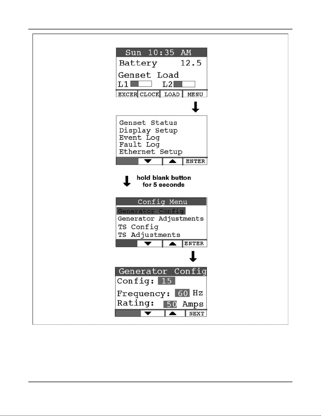
7. Startup and Configuration 6-2016
FIGURE 58. GENERATOR CONFIGURATION
7.5 Transfer Switch Configuration
To configure the generator set for the transfer switch being used:
1. Press the MENU button on the home screen.
78 A029V088 (Issue 22)Copyright © 2016 Cummins Inc.
Page 85

7. Startup and Configuration6-2016
2. Press and hold the blank button on the menu screen for at least 5 seconds to go to the Config Menu.
3. Press the up or down arrow button on the Config Menu screen to select TS Config.
4. Press Enter on the Config Menu to go to the Transfer Switch screen.
5. Press the up or down arrow button to select between two choices: “RSS100-6868 and RSS2006869" or “RSS100-6634 and RSS200-6635," which must match the model number of the transfer
switch being used.
NOTICE
For non-Cummins Power Generation transfer switches, select RSS100-6634 and RSS100-
6635.
6. Press the BACK button to save the setting and return to the home screen.
FIGURE 59. TRANSFER SWITCH CONFIGURATION
79A029V088 (Issue 22) Copyright © 2016 Cummins Inc.
Page 86

7. Startup and Configuration 6-2016
7.6 Transfer Switch Parameter Adjustments
Model RSS100-6634 and RSS200-6635 Transfer Switches: Refer to Transfer Switch Installation Manual
962-0620 to set the parameters inside the transfer switch.
Model RSS100-6868 and RSS200-6869 Transfer Switches: To make transfer switch parameter
adjustments:
1. Press the MENU button on the home screen.
2. Press and hold the blank button on the menu screen for at least 5 seconds to go to the Config Menu.
3. Press the up or down arrow button on the Config Menu screen to select TS Adjustments.
4. Press Enter on the Config Menu to go to the Transfer Switch screen.
5. Press the NEXT button on the Generator Config Menu screen to select the Pickup, Dropout or
Nominal field.
6. To set Nominal - Press the up or down double-arrow button to increase or decrease the nominal
utility voltage parameter to match actual (Present) utility voltage. The Pickup and Dropout
parameters are percentages of the nominal voltage parameter.
7. To set Pickup- Press the up or down double-arrow button to increase or decrease the minimum
utility voltage to which the transfer switch will connect. Default is 90% of nominal. It can be increased
to 95% of nominal.
8. To set Dropout- Press the up or down double-arrow button to increase or decrease the minimum
utility voltage at which the transfer switch will disconnect. Default is 85% of nominal. It can be
decreased to 80/75/70% of nominal.
9. Press the BACK button to save the setting and return to the home screen.
80 A029V088 (Issue 22)Copyright © 2016 Cummins Inc.
Page 87

7. Startup and Configuration6-2016
FIGURE 60. TRANSFER SWITCH ADJUSTMENTS
7.7 Generator Adjustments
7.7.1 To Adjust the Output Voltage
Use the following procedure:
1. Connect an accurate AC volt meter across L1 and L2 while the generator set is running.
2. With Output Volts selected on the Adjustments Menu screen, press the up or down arrow button to
adjust the voltage to the desired setting
3. The control allows an adjustment of 240 VAC ± 7% (17 VAC).
4. Press the BACK button to save the settings and return to the home screen.
81A029V088 (Issue 22) Copyright © 2016 Cummins Inc.
Page 88

7. Startup and Configuration 6-2016
7.7.2 To Calibrate the Display Meter
Use the following procedure:
1. Connect an accurate AC volt meter across L1 and L2 while the generator set is running.
2. Press the NEXT button to select the Display Cal field (screen not shown).
3. Press the up or down arrow to adjust the voltage reading on the screen until it matches the meter
reading.
4. Press the BACK button to save the settings and return to the home screen.
FIGURE 61. ADJUSTMENT MENU SCREEN
82 A029V088 (Issue 22)Copyright © 2016 Cummins Inc.
Page 89

8 Communication Troubleshooting
8.1 In-Home Network Access to Generator Set
Troubleshooting
WARNING
Some generator set service procedures present hazards that can result in severe personal injury
or death. Only trained and experienced service personnel with knowledge of fuels, electricity,
and machinery hazards should perform generator set service.
Possible Causes: Bad connections or bad communications
Corrective Actions:
1. Check connections.
a. Verify that the Ethernet cable is plugged into the generator set control and the router.
b. Verify that the computer that is attempting to access the generator set is connected to the
same router as the generator set via an Ethernet cable (on the same local area network).
c. Verify that the wireless card on the computer is turned off.
d. Check to see if both ends of the Ethernet cable are assembled and crimped as described in the
installation instructions. If not, reassemble and crimp as described in the installation
instructions.
e. Verify that the Ethernet cable connections between the generator set and the router are solid
and correct.
f. Proceed to "Check communications."
2. Check communications.
a. If the router is also connected to an incoming connection from an ISP, check to see if you can
access a standard web page with the computer connected to the same router as the generator
set. If not, contact your router manufacturer for troubleshooting information.
b. Check to see if the green and orange lights are illuminated at the Ethernet connection port on
the generator set control board. If the lights are not illuminated, this indicates that no
information is being transmitted or received. Test the cable by disconnecting the Ethernet cable
from the generator control board and connecting it to the computer (swap the cable with the
existing Ethernet cable). With the router connected to the ISP, check to see if you can access a
standard web page.
i. If you can access a standard web page, call Cummins Support at 1-800-888-6626 and
select option 1.
ii. If you cannot access a standard web page, go to the “Check connections" step above.
c. Check to see if the correct generator IP address has been entered. If not, enter the correct IP
address in the address bar of the web browser. Be sure to not enter "www" or other text prior to
the IP address.
d. If none of the above troubleshooting techniques help, call Cummins Support at 1-800-888-6626
and select option 1.
83A029V088 (Issue 22) Copyright © 2016 Cummins Inc.
Page 90

8. Communication Troubleshooting 6-2016
FIGURE 62. NETWORK CONNECTIONS (CONTROL BOARD AND ETHERNET CONNECTION)
8.2 Remote Internet Access to Generator Set Troubleshooting
WARNING
Some generator set service procedures present hazards that can result in severe personal injury
or death. Only trained and experienced service personnel with knowledge of fuels, electricity,
and machinery hazards should perform generator set service.
Possible Causes: Improper setup, no high-speed internet connection, public IP address is not active or
properly set up, incorrect IP address is entered, computer is connected to the same router or network as
the generator set, or the internet connection is faulty.
Corrective Actions:
1. Check to see if you are able to access the generator set with your in-home computer.
If not, refer to the In-Home Network Access Troubleshooting procedures.
2. Verify that you followed the network setup procedures.
Refer to the Network Setup Guide.
3. Verify that you are using a high-speed internet connection.
4. Verify that the public IP address is active and set up properly with the ISP (Internet Service
Provider). If necessary, contact the ISP to verify your setup.*
5. Verify that the correct public IP address is entered into the web browser of the computer (i.e.
xxx.xxx.xxx.xxx).
6. Verify that the computer is not connected to the same router or local area network as the generator
set. If it is on the same network, you will be able to access the generator set using the local network
IP address configured on the generator set. The computer used for internet access must be
connected to a different internet connection than the generator set.
84 A029V088 (Issue 22)Copyright © 2016 Cummins Inc.
Page 91

7. Check to see if you can access a standard web page from a computer. If not, contact the ISP to
troubleshoot the internet connection.
8. Verify all settings, as described in the Network Setup Guide.
9. If the previous steps do not correct the problem, contact a computer network specialist to diagnose.
* To verify your IP address, access “whatismyipaddress.com" from the browser of a computer
connected to the internet and on the same network as the generator set. This web page displays
your current IP address which should match the IP address assigned to you by your ISP.
8.3 Email Alert Troubleshooting
WARNING
Some Generator Set service procedures present hazards that can result in severe personal injury
or death. Only trained and experienced service personnel with knowledge of fuels, electricity,
and machinery hazards should perform Generator Set service.
Possible Causes: An improper setup, the alert level is not set to “all events," emails cannot be received,
the outgoing email address is not included in your contact list, the email account is not capable of using
plain SMTP for the outgoing SMTP server setup, the domain name is not included in the user name filed
of the Network Setup screen, or the DNS #1 and #2 values are incorrect on the Network Setup screen.
8. Communication Troubleshooting6-2016
Corrective Actions:
1. Check to see if you are able to access the generator set with your in-home computer. If not, refer to
In-Home Computer Access Troubleshooting.
2. Verify that you followed the network setup instructions. Refer to the Network Setup Guide.
3. Verify that the alert level is set to All Events.
a. To verify that your generator set can send emails, select Disable Standby and wait several
minutes to verify that you did receive an email.
b. Select Enable Standby and wait a few more minutes to verify that you did receive a second
email.
4. Send an email to the destination email address and check to see if you received this email.
If not, contact your email service provider or your ISP (Internet service provider) to diagnose.
5. Check to see if the destination email accounts have spam filtering.
a. If spam filtering is present, add the outgoing email address to your contact list.
b. If spam filtering is not present, proceed to step 6.
6. Ensure that the SMTP server in use is capable of distributing non SSL certified emails. If the SMTP
server is not capable of sending non SSL certified emails or the status is unknown, please contact
your ISP technical support for information.
7. Verify that the domain name is included in the user name field of the Network Setup screen (i.e.
username@domainname).**
8. Verify with your ISP that the Static DNS (Domain Name Server) #1 and #2 are correct.
9. If the previous steps do not correct the problem, contact a computer network specialist to diagnose.
** “No authentication" is possible on some systems by leaving the username and password fields blank.
IMPORTANT NOTE: Changes are not saved unless you navigate through all three Network Setup
screens and click on “Done". The message “Settings Saved Successfully" is then displayed.
85A029V088 (Issue 22) Copyright © 2016 Cummins Inc.
Page 92
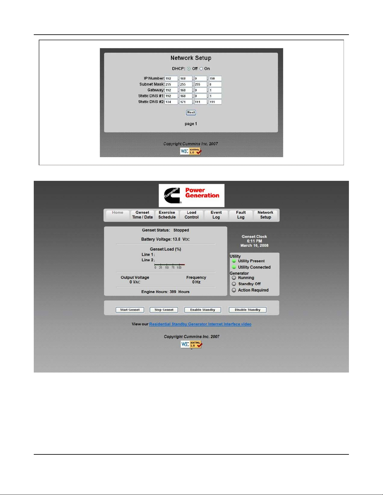
8. Communication Troubleshooting 6-2016
FIGURE 63. NETWORK SETUP - PAGE 1
FIGURE 64. GENERATOR SET HOME PAGE
86 A029V088 (Issue 22)Copyright © 2016 Cummins Inc.
Page 93
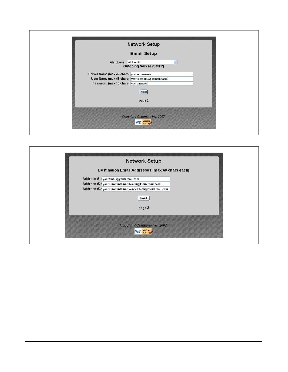
FIGURE 65. NETWORK SETUP - PAGE 2
8. Communication Troubleshooting6-2016
FIGURE 66. NETWORK SETUP - PAGE 3
87A029V088 (Issue 22) Copyright © 2016 Cummins Inc.
Page 94

8. Communication Troubleshooting 6-2016
This page is intentionally blank.
88 A029V088 (Issue 22)Copyright © 2016 Cummins Inc.
Page 95

Appendix A. Outline and System Drawings
Table of Contents
Figure 67. Ethernet Connector .................................................................................................................. 90
Figure 68. ethernet RJ-45 connector Wiring ............................................................................................ 90
Figure 69. Network Connections ................................................................................................................ 91
Figure 70. Manual Fuel Selection Valve ..................................................................................................... 92
Figure 71. Wiring Diagram (Sheet 1 of 3) ................................................................................................... 93
Figure 72. Wiring Diagram (Sheet 2 of 3) ................................................................................................... 94
Figure 73. Wiring Diagram (Sheet 3 of 3) ................................................................................................... 95
Figure 74. Harness Label ............................................................................................................................. 96
Figure 75. Wiring Harness Connections (Sheet 1 of 4) ............................................................................ 97
Figure 76. Wiring Harness Connections (Sheet 2 of 4) ............................................................................ 98
Figure 77. Wiring Harness Connections (Sheet 3 of 4) ............................................................................ 99
Figure 78. Wiring Harness Connections (Sheet 4 of 4) .......................................................................... 100
Figure 79. Outline Drawing ........................................................................................................................ 101
89A029V088 (Issue 22) Copyright © 2016 Cummins Inc.
Page 96

Appendix A. Outline and System Drawings 6-2016
Wiring connections to the Ethernet RJ-45 plug are shown in the Ethernet RJ-45 Connector
Wiring illustration. Utilize an appropriate Ethernet stripping and crimping tool for these
connections.
FIGURE 67. ETHERNET CONNECTOR
FIGURE 68. ETHERNET RJ-45 CONNECTOR WIRING
90 A029V088 (Issue 22)Copyright © 2016 Cummins Inc.
Page 97
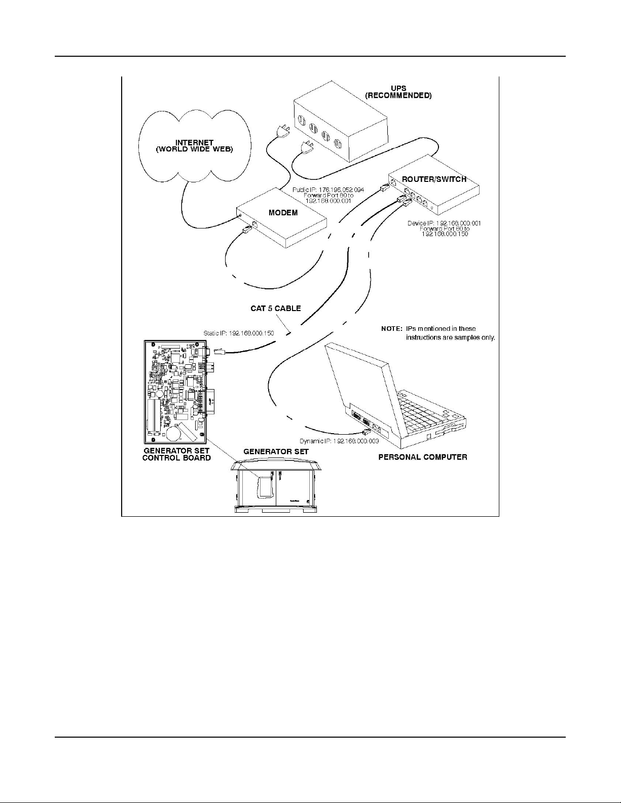
Appendix A. Outline and System Drawings6-2016
FIGURE 69. NETWORK CONNECTIONS
91A029V088 (Issue 22) Copyright © 2016 Cummins Inc.
Page 98

Appendix A. Outline and System Drawings 6-2016
FIGURE 70. MANUAL FUEL SELECTION VALVE
92 A029V088 (Issue 22)Copyright © 2016 Cummins Inc.
Page 99
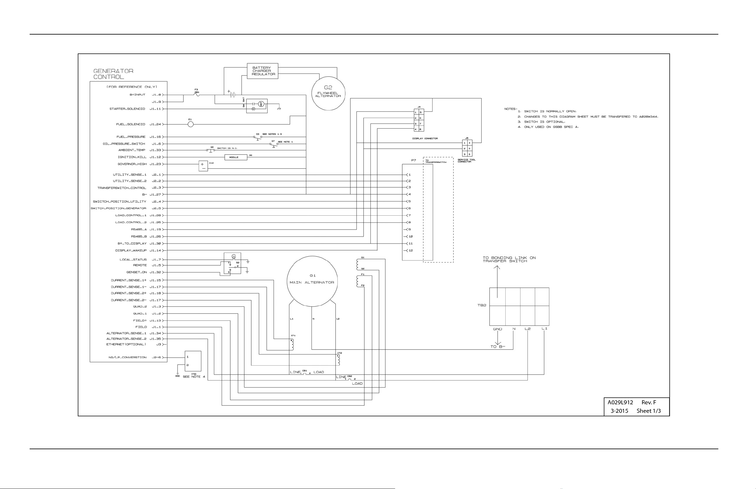
Appendix A. Outline and System Drawings6-2016
FIGURE 71. WIRING DIAGRAM (SHEET 1 OF 3)
93A029V088 (Issue 22)
Copyright © 2016 Cummins Inc.
Page 100

Appendix A. Outline and System Drawings 6-2016
Copyright © 2016 Cummins Inc.
FIGURE 72. WIRING DIAGRAM (SHEET 2 OF 3)
94 A029V088 (Issue 22)
 Loading...