

Page 1
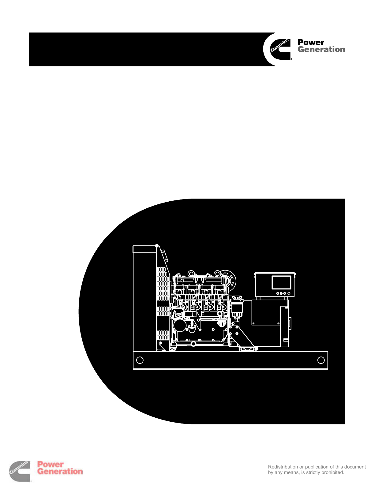
Installation Manual
Redistribution or publication of this document
by any means, is strictly prohibited.
GenSet Model
DNAC, DNAD, DNAE, DNAF
with PowerCommand Control
PCC1301
Printed in U.S.A.
967-0605B 01-2006
Page 2

Redistribution or publication of this document
by any means, is strictly prohibited.
Page 3

Table of Contents
Redistribution or publication of this document
by any means, is strictly prohibited.
SECTION TITLE PAGE
IMPORTANT SAFETY INSTRUCTIONS iii. . . . . . . . . . . . . . . . . . . . . . . . . . . . . . .
1 INTRODUCTION
About this Manual 1-1. . . . . . . . . . . . . . . . . . . . . . . . . . . . . . . . . . . . . . . . . . . . . . .
Installation Overview 1-1. . . . . . . . . . . . . . . . . . . . . . . . . . . . . . . . . . . . . . . . . . . . .
2 SPECIFICATIONS 2-1. . . . . . . . . . . . . . . . . . . . . . . . . . . . . . . . . . . . . . . . . . . . . . . . .
3 MECHANICAL
Location 3-1. . . . . . . . . . . . . . . . . . . . . . . . . . . . . . . . . . . . . . . . . . . . . . . . . . . . . . . .
Access and Lighting 3-1. . . . . . . . . . . . . . . . . . . . . . . . . . . . . . . . . . . . . . . . . . . . .
Mounting 3-1. . . . . . . . . . . . . . . . . . . . . . . . . . . . . . . . . . . . . . . . . . . . . . . . . . . . . . .
Engine Exhaust 3-2. . . . . . . . . . . . . . . . . . . . . . . . . . . . . . . . . . . . . . . . . . . . . . . . .
Cooling and Ventilation 3-3. . . . . . . . . . . . . . . . . . . . . . . . . . . . . . . . . . . . . . . . . . .
Fuel 3-5. . . . . . . . . . . . . . . . . . . . . . . . . . . . . . . . . . . . . . . . . . . . . . . . . . . . . . . . . . .
4 DC CONTROL WIRING
Control Wiring 4-1. . . . . . . . . . . . . . . . . . . . . . . . . . . . . . . . . . . . . . . . . . . . . . . . . . .
TB1 Remote Monitor/Control Connections 4-2. . . . . . . . . . . . . . . . . . . . . . . . . .
Switched B+ 4-2. . . . . . . . . . . . . . . . . . . . . . . . . . . . . . . . . . . . . . . . . . . . . . . . . . . .
Universal Annunciator 4-2. . . . . . . . . . . . . . . . . . . . . . . . . . . . . . . . . . . . . . . . . . . .
I/O Module 4-3. . . . . . . . . . . . . . . . . . . . . . . . . . . . . . . . . . . . . . . . . . . . . . . . . . . . . .
Run Relays (K10, K11) 4-3. . . . . . . . . . . . . . . . . . . . . . . . . . . . . . . . . . . . . . . . . . .
Batteries 4-4. . . . . . . . . . . . . . . . . . . . . . . . . . . . . . . . . . . . . . . . . . . . . . . . . . . . . . .
California
Proposition 65 Warning
Diesel engine exhaust and some of its constituents are known
to the State of California to cause cancer, birth defects, and
other reproductive harm.
i
Page 4

SECTION TITLE PAGE
Redistribution or publication of this document
by any means, is strictly prohibited.
5 AC ELECTRICAL CONNECTIONS
General 5-1. . . . . . . . . . . . . . . . . . . . . . . . . . . . . . . . . . . . . . . . . . . . . . . . . . . . . . . .
Transfer Switch 5-2. . . . . . . . . . . . . . . . . . . . . . . . . . . . . . . . . . . . . . . . . . . . . . . . .
AC Wiring 5-3. . . . . . . . . . . . . . . . . . . . . . . . . . . . . . . . . . . . . . . . . . . . . . . . . . . . . .
Control Heater (Optional) 5-6. . . . . . . . . . . . . . . . . . . . . . . . . . . . . . . . . . . . . . . . .
Coolant Heater (Optional) 5-6. . . . . . . . . . . . . . . . . . . . . . . . . . . . . . . . . . . . . . . .
Generator Heater (Optional) 5-6. . . . . . . . . . . . . . . . . . . . . . . . . . . . . . . . . . . . . .
6 PRESTART PREPARATION
General 6-1. . . . . . . . . . . . . . . . . . . . . . . . . . . . . . . . . . . . . . . . . . . . . . . . . . . . . . . .
InPower Service Tool General Information 6-1. . . . . . . . . . . . . . . . . . . . . . . . . .
Electrical System 6-1. . . . . . . . . . . . . . . . . . . . . . . . . . . . . . . . . . . . . . . . . . . . . . . .
PCC Options Prestart Checks 6-2. . . . . . . . . . . . . . . . . . . . . . . . . . . . . . . . . . . . .
Screen Adjust Menu 6-2. . . . . . . . . . . . . . . . . . . . . . . . . . . . . . . . . . . . . . . . . . . . .
Starting 6-4. . . . . . . . . . . . . . . . . . . . . . . . . . . . . . . . . . . . . . . . . . . . . . . . . . . . . . . .
7 INSTALLATION CHECKLIST
General 7-1. . . . . . . . . . . . . . . . . . . . . . . . . . . . . . . . . . . . . . . . . . . . . . . . . . . . . . . .
Generator Set Support 7-1. . . . . . . . . . . . . . . . . . . . . . . . . . . . . . . . . . . . . . . . . . .
Cooling Air Flow 7-1. . . . . . . . . . . . . . . . . . . . . . . . . . . . . . . . . . . . . . . . . . . . . . . . .
Diesel Fuel System 7-1. . . . . . . . . . . . . . . . . . . . . . . . . . . . . . . . . . . . . . . . . . . . . .
Exhaust System 7-2. . . . . . . . . . . . . . . . . . . . . . . . . . . . . . . . . . . . . . . . . . . . . . . . .
AC and DC Wiring 7-2. . . . . . . . . . . . . . . . . . . . . . . . . . . . . . . . . . . . . . . . . . . . . . .
Generator Set Prestart 7-2. . . . . . . . . . . . . . . . . . . . . . . . . . . . . . . . . . . . . . . . . . .
8 WIRING DIAGRAMS
Customer Connection Diagram 8-1. . . . . . . . . . . . . . . . . . . . . . . . . . . . . . . . . . . .
ii
Page 5
IMPORTANT SAFETY INSTRUCTIONS
Redistribution or publication of this document
by any means, is strictly prohibited.
SAVE THESE INSTRUCTIONS – This manual contains
important instructions that should be followed during
installation and maintenance of the generator and batteries.
Before operating the generator set (genset), read the
Operator’s Manual and become familiar with it and the
equipment. Safe and efficient operation can be
achieved only if the equipment is properly operated
and maintained. Many accidents are caused by failure
to follow fundamental rules and precautions.
The following symbols, found throughout this manual,
alert you to potentially dangerous conditions to the operator, service personnel, or the equipment.
This symbol warns of immediate
hazards which will result in severe personal injury or death.
WARNING
This symbol refers to a hazard or unsafe practice which can result in severe personal injury or death.
CAUTION
This symbol refers to a hazard or unsafe practice which can result in personal injury
or product or property damage.
FUEL AND FUMES ARE FLAMMABLE
Fire, explosion, and personal injury or death can result
from improper practices.
• DO NOT fill fuel tanks while engine is running, un-
less tanks are outside the engine compartment.
Fuel contact with hot engine or exhaust is a potential
fire hazard.
• DO NOT permit any flame, cigarette, pilot light,
spark, arcing equipment, or other ignition source
near the generator set or fuel tank.
• Fuel lines must be adequately secured and free of
leaks. Fuel connection at the engine should be
made with an approved flexible line. Do not use zinc
coated or copper fuel lines with diesel fuel.
• Be sure all fuel supplies have a positive shutoff
valve.
• Be sure battery area has been well-ventilated prior
to servicing near it. Lead-acid batteries emit a highly
explosive hydrogen gas that can be ignited by arcing, sparking, smoking, etc.
EXHAUST GASES ARE DEADLY
•
Provide an adequate exhaust system to properly
expel discharged gases away from enclosed or
sheltered areas and areas where individuals are
likely to congregate. Visually and audibly inspect
the exhaust daily for leaks per the maintenance
schedule. Make sure that exhaust manifolds are secured and not warped. Do not use exhaust gases to
heat a compartment.
• Be sure the unit is well ventilated.
• Engine exhaust and some of its constituents are
known to the state of California to cause cancer,
birth defects, and other reproductive harm.
MOVING PARTS CAN CAUSE SEVERE
PERSONAL INJURY OR DEATH
Keep your hands, clothing, and jewelry away from
•
moving parts.
• Before starting work on the generator set, discon-
nect battery charger from its AC source, then disconnect starting batteries, negative (–) cable first.
This will prevent accidental starting.
• Make sure that fasteners on the generator set are
secure. Tighten supports and clamps, keep guards
in position over fans, drive belts, etc.
• Do not wear loose clothing or jewelry in the vicinity of
moving parts, or while working on electrical equipment. Loose clothing and jewelry can become
caught in moving parts.
• If adjustment must be made while the unit is run-
ning, use extreme caution around hot manifolds,
moving parts, etc.
DO NOT OPERATE IN FLAMMABLE AND
EXPLOSIVE ENVIRONMENTS
Flammable vapor can cause an engine to overspeed and
become difficult to stop, resulting in possible fire, explosion, severe personal injury and death. Do not operate a
genset where a flammable vapor environment can be
created by fuel spill, leak, etc., unless the genset is
equipped with an automatic safety device to block the air
intake and stop the engine. The owners and operators of
the genset are solely responsible for operating the genset safely. Contact your authorized Cummins Power
Generation distributor for more information.
LS-14L
iii
Page 6

ELECTRICAL SHOCK CAN CAUSE
Redistribution or publication of this document
by any means, is strictly prohibited.
SEVERE PERSONAL INJURY OR DEATH
•
Remove electric power before removing protective
shields or touching electrical equipment. Use rubber insulative mats placed on dry wood platforms
over floors that are metal or concrete when around
electrical equipment. Do not wear damp clothing
(particularly wet shoes) or allow skin surface to be
damp when handling electrical equipment. Do not
wear jewelry. Jewelry can short out electrical contacts and cause shock or burning.
• Use extreme caution when working on electrical
components. High voltages can cause injury or
death. DO NOT tamper with interlocks.
• Follow all applicable state and local electrical
codes. Have all electrical installations performed by
a qualified licensed electrician. Tag and lock open
switches to avoid accidental closure.
• DO NOT CONNECT GENERATOR SET DIRECT-
LY TO ANY BUILDING ELECTRICAL SYSTEM.
Hazardous voltages can flow from the generator set
into the utility line. This creates a potential for electrocution or property damage. Connect only
through an approved isolation switch or an approved paralleling device.
GENERAL SAFETY PRECAUTIONS
Coolants under pressure have a higher boiling point
•
than water. DO NOT open a radiator or heat exchanger pressure cap while the engine is running.
Allow the generator set to cool and bleed the system
pressure first.
• Used engine oils have been identified by some state
or federal agencies as causing cancer or reproductive toxicity. When checking or changing engine oil,
take care not to ingest, breathe the fumes, or contact used oil.
• Keep multi-class ABC fire extinguishers handy.
Class A fires involve ordinary combustible materials
such as wood and cloth; Class B fires, combustible
and flammable liquid fuels and gaseous fuels; Class
C fires, live electrical equipment. (ref. NFPA No. 10).
• Make sure that rags are not left on or near the en-
gine.
• Make sure generator set is mounted in a manner to
prevent combustible materials from accumulating
under the unit.
• Remove all unnecessary grease and oil from the
unit. Accumulated grease and oil can cause overheating and engine damage which present a potential fire hazard.
• Keep the generator set and the surrounding area
clean and free from obstructions. Remove any debris from the set and keep the floor clean and dry.
• Do not work on this equipment when mentally or
physically fatigued, or after consuming any alcohol
or drug that makes the operation of equipment unsafe.
• Substances in exhaust gases have been identified
by some state or federal agencies as causing cancer or reproductive toxicity. Take care not to breath
or ingest or come into contact with exhaust gases.
• Do not store any flammable liquids, such as fuel,
cleaners, oil, etc., near the generator set. A fire or
explosion could result.
• Wear hearing protection when going near an oper-
ating generator set.
• To prevent serious burns, avoid contact with hot
metal parts such as radiator, turbo charger and exhaust system.
KEEP THIS MANUAL NEAR THE GENSET FOR EASY REFERENCE
iv
Page 7

1. Introduction
Redistribution or publication of this document
by any means, is strictly prohibited.
ABOUT THIS MANUAL
This manual provides installation instructions for
the generator set models listed on the front cover.
This includes the following information:
Mounting Recommendations - for fastening
generator set to base and space requirements
for normal operation and service.
Mechanical and Electrical Connections covers most aspects of the generator set installation.
Prestart – checklist of items or procedures
needed to prepare generator set for operation.
Initial Startup – test complete system to ensure proper installation, satisfactory performance, and safe operation. Refer to Operators
Manual for troubleshooting information.
Installation Checklist – reference checks
upon completion of installation.
This manual DOES NOT provide application information for selecting a generator set or designing the
complete installation. If it is necessary to design the
various integrated systems (fuel, exhaust, cooling,
etc.), additional information is required. Review
standard installation practices. For engineering
data specific to the generator set, refer to the Speci-
fication and Data Sheets. For application information, refer to Application Manual T-030, “Liquid
Cooled Generator Sets”.
INSTALLATION OVERVIEW
These installation recommendations apply to typical installations with standard model generator
sets. Whenever possible, these recommendations
also cover factory designed options or modifica-
tions. However, because of the many variables in
any installation, it is not possible to provide specific
recommendations for every situation. If there are
any questions not answered by this manual, contact
your nearest Cummins Power Generation distributor for assistance.
Application and Installation
A power system must be carefully planned and correctly installed for proper operation. This involves
two essential elements: application and installation.
Application (as it applies to generator set installations) refers to the design of the complete power
system that usually includes power distribution
equipment, transfer switches, ventilation equipment, mounting pads, and cooling, exhaust, and
fuel systems. Each component must be correctly
designed so the complete system will function as intended. Application and design is an engineering
function generally done by specifying engineers or
other trained specialists. Specifying engineers or
other trained specialists are responsible for the design of the complete power system and for selecting
the materials and products required.
Installation refers to the actual set-up and assembly of the power system. The installers set up and
connect the various components of the system as
specified in the system design plan. The complexity
of the system normally requires the special skills of
qualified electricians, plumbers, sheetmetal workers, etc. to complete the various segments of the
installation. This is necessary so all components
are assembled using standard methods and practices.
1-1
Page 8

Safety Considerations
Redistribution or publication of this document
by any means, is strictly prohibited.
The generator set has been carefully designed to
provide safe and efficient service when properly
installed, maintained, and operated. However, the
overall safety and reliability of the complete system
is dependent on many factors outside the control of
the generator set manufacturer. To avoid possible
safety hazards, make all mechanical and electrical
connections to the generator set exactly as specified in this manual. All systems external to the generator (fuel, exhaust, electrical, etc.) must comply
with all applicable codes. Make certain all required
inspections and tests have been completed and all
code requirements have been satisfied before certifying the installation is complete and ready for service.
Standby Heating Devices
In accordance with NFPA 110, Cummins Power
Generation recommends installing standby generator sets (life safety systems) equipped with engine
jacket water coolant heaters in locations where the
minimum ambient temperature is above 40
(4
°C). NFPA also requires that the engine be
heated as necessary to maintain the water jacket
temperature determined by the manufacturer for
cold start and load acceptance for the type of system. Although most Cummins Power Generation
generator sets will start in temperatures down to
–25
°F (–32°C) when equipped with engine jacket
°F
water coolant heaters, it might take more than 10
seconds to warm the engine before a load can be
applied when ambient temperatures are below
40
°F (4°C).
On generator sets equipped with a graphic display,
the Low Coolant Temperature (Code 203) mes-
sage, in conjunction with illumination of the Warning
LED, is provided to meet the requirements of NFPA
110. The engine cold sensing logic initiates a warning when the engine jacket water coolant temperature falls below 70
the ambient temperature falls below 40
°F (21°C). In applications where
°F (4°C), a
cold engine may be indicated even though the coolant heaters are connected and operating correctly.
Under these conditions, although the generator set
may start, it may not be able to accept load within 10
seconds. When this condition occurs, check the
coolant heaters for proper operation. If the coolant
heaters are operating properly, other precautions
may be necessary to warm the engine before applying a load.
Product Modifications
Agency certified products purchased from Cummins Power Generation comply only with those
specific requirements and as noted on company
product specification sheets. Subsequent modifications must meet commonly accepted engineering
practices and/or local and national codes and standards. Product modifications must be submitted to
the local authority having jurisdiction for approval.
Copyright 2005 Cummins Power Generation. All rights reserved.
Cummins and PowerCommand are registered trademarks of Cummins Inc.
1-2
Page 9

2. Specifications
Redistribution or publication of this document
by any means, is strictly prohibited.
MODEL
DNAC DNAD DNAE DNAF
GENERATOR: Single-Bearing, 4-Pole Rotating Field, Brushless, Microprocessor Regulated. See Generator Set
Nameplate for Rating.
ENGINE: Mechanically or Microprocessor Governed 4-Stroke Cycle Direct-Injection Diesel
Number of Cylinders 2 3 4 4
Bore
Stroke
Displacement
Compression Ratio 18.5:1 18.5:1 18.5:1 16.2:1
Firing Order 1-2 1-2-3 1-3-4-2 1-3-4-2
Aspiration Natural Natural Natural Turbocharger
Cooling Method Water Water Water Water
Engine Coolant Capacity
(Engine and Radiator)
Engine Oil Capacity*
Fuel Injection Timing 19-21° BTDC
Rotation
Valve Lash
Maximum Fuel Pump Lift 3 meter (10 feet)
Fuel Supply Connection 6 mm (0.24 inch) ID Hose Fitting
Fuel Return Connection 3.5 mm (0.14 inch) ID Hose Fitting
BATTERIES:**
Nominal Battery Voltage 12 volts
Minimum CCA (Cold Crank-
ing Amps) Rating
Charging Alternator Output 45 amps
INSTALLATION SPECIFICATIONS:
See the appropriate Specification Bulletin and Outline Drawing for maximum exhaust gas back pressure; minimum cooling air flow; fuel consumption rate; fuel, exhaust and electrical connection points; overall dimensions;
weight; etc.
* Includes Oil Filter
** A battery mounted in the built-in battery rack in the skid base must be of a type with barbed vent hose fittings for its cells. The vent lines
must be routed away from the generator end bell (air inlet) to prevent battery gasses from entering the generator and causing corrosion.
86.0 mm
(3.38 inch)
80 mm
(3.15 inch)
0.93 liter
56.75 in
6.5 liter
(6.8 quart)
3.2 liter
(3.4 quart)
3
Clockwise (looking at the fan or radiator end)
86.0 mm
(3.38 inch)
80 mm
(3.15 inch)
1.395 liter
85.13 in
7.1 liter
(7.5 quart)
4.4 liter
(4.7 quart)
3
Hydraulic tappets
525 amps
86.0 mm
(3.38 inch)
80 mm
(3.15 inch)
1.860 liter
113.50 in
7.6 liter
(8.0 quart)
5.7 liter
(6.1 quart)
86.0 mm
(3.38 inch)
80 mm
(3.15 inch)
3
1.860 liter
113.50 in
7.6 liter
(8.0 quart)
5.7 liter
(6.1 quart)
3
2-1
Page 10

THIS PAGE LEFT INTENTIONALLY BLANK
Redistribution or publication of this document
by any means, is strictly prohibited.
2-2
Page 11
3. Mechanical
Redistribution or publication of this document
by any means, is strictly prohibited.
LOCATION
Generator set location is a matter for system design
and application (see Introduction). Factors such as
engine exhaust, noise, ventilation, ambient temperature, security, location of the distribution switchboard, foundation or supporting structure and access for maintenance and service all affect the decision about where to locate the generator set.
Weather/vandal-protective housings are available
for outdoor installations.
ACCESS AND LIGHTING
Generally, at least 1 meter (3 feet) of clearance
should be provided on all sides of the generator set
for maintenance and service access. A raised
foundation or slab of 150 mm (6 inches) or more
above floor level will make servicing easier.
Lighting should be adequate for operation, maintenance and service operations and should be connected on the load side of the transfer switch so that
it is available at all times.
MOUNTING
The foundation, floor or roof must be level and be
able to support the weight of the generator set, resist the dynamic loads and not transmit objectionable noise and vibration. The generator set has a
skid base with elastomer vibration isolators between the generator assembly and skid base. Generally, additional vibration isolation is not required.
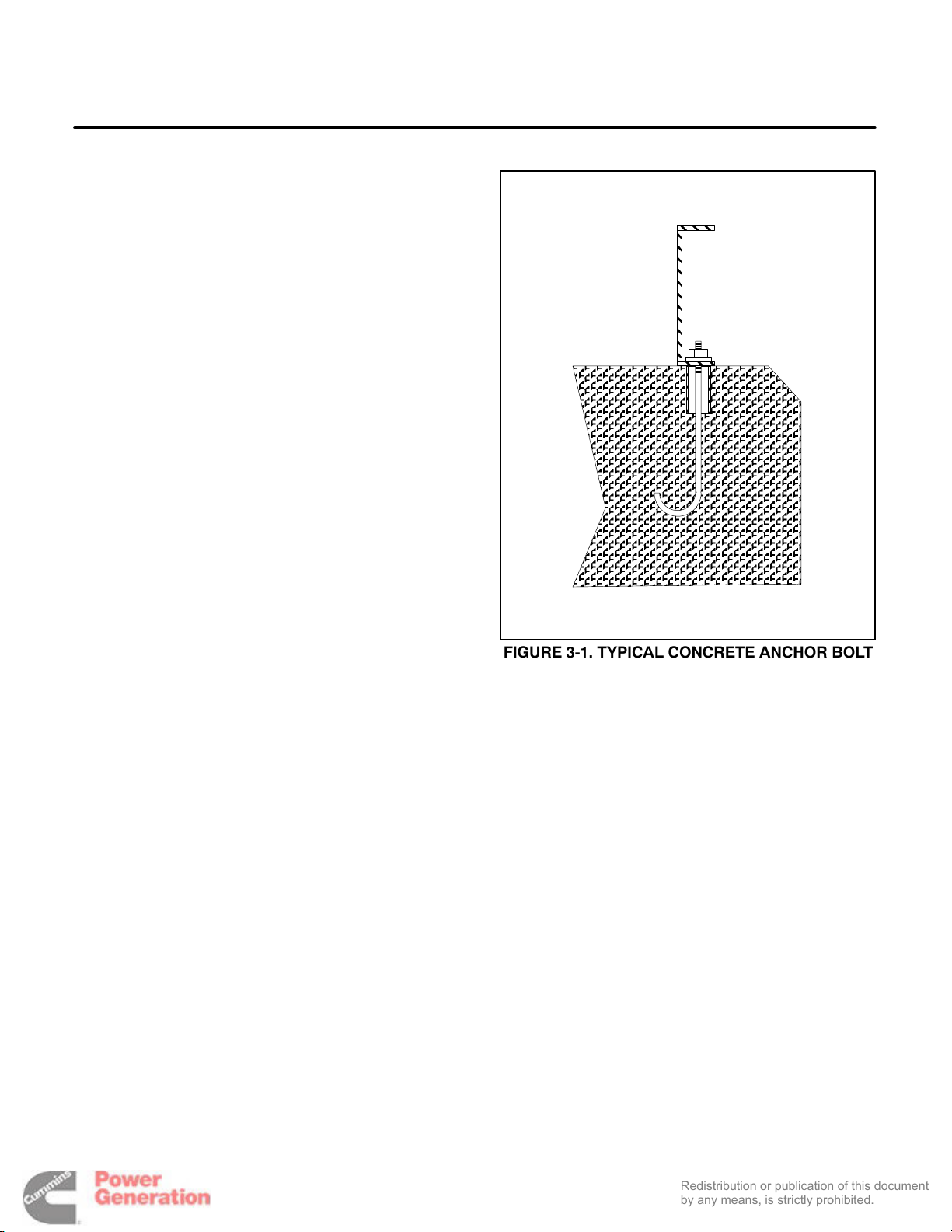
See the appropriate outline drawing for the anchor
bolt hole locations in the skid base or mounting
brackets. Figure 3-1 illustrates a typical anchor bolt
for concrete foundations.
FIGURE 3-1. TYPICAL CONCRETE ANCHOR BOLT
3-1
Page 12
ENGINE EXHAUST
Redistribution or publication of this document
by any means, is strictly prohibited.
The engine exhaust system must be gas-tight. It
must convey engine exhaust safely to the out-ofdoors and disperse the fumes, soot and noise away
from people and buildings.
WARNING
EXHAUST GAS IS DEADLY! The exhaust system must be gas-tight and terminate
away from buildings and building vents, windows and doors and areas where exhaust can
accumulate.
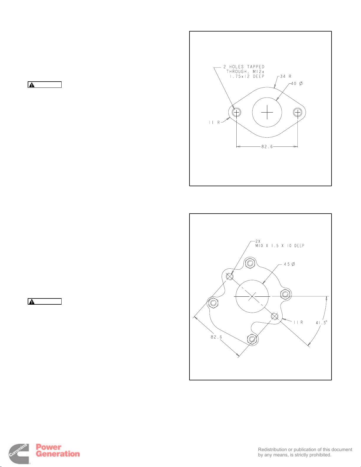
Schedule 40 black iron pipe is recommended for exhaust piping. Figures 3-2 and 3-3 are the exhaust
flange drawings for connections at the engine. Engine-mounted mufflers are available as an option
and have 1-1/4 inch NPT outlet connections.
Flexible, corrugated stainless steel exhaust tubing
at least 457 mm (18 inches) long must be connected between the engine or engine mounted muffler and exhaust piping. It must not be used to form
bends or to compensate for misaligned piping.
Mufflers (other than engine-mounted) and piping
must be supported on non-combustible hangers so
that the weight does not cause damage to the engine manifold or turbocharger.
Exhaust piping must be shielded or insulated by approved methods or be routed not closer than
229 mm (9 inches) to combustible material. Use an
approved thimble (Figure 3-4) where exhaust piping passes through a combustible wall, partition,
ceiling or roof.
FIGURE 3-2 EXHAUST FLANGE—NON-TURBO-
CHARGED ENGINES
WARNING
Exhaust piping can ignite combustible material. Use approved methods for routing, insulating and shielding exhaust pipe.
A rain cap must be provided if the exhaust outlet
points up.
Horizontal runs of piping should slope downwards
away from the engine to a condensate trap or to the
outlet. A condensate drain tap and plug should be
provided where piping turns to rise vertically.
Exhaust backpressure under full load must not exceed that specified on the Specification Sheet. Pipe
bends should be sweeping and pipe diameter
should be at least the same as, but never smaller
than, the outlet at the engine or mounted muffler.
See Application Manual T-030 for a method for calculating and testing exhaust backpressure.
FIGURE 3-3 EXHAUST FLANGE—TURBO-
CHARGED ENGINES
3-2
Page 13

COOLING AND VENTILATION
Redistribution or publication of this document
by any means, is strictly prohibited.
Generator sets dissipate heat and fumes that must
be removed by proper cooling and ventilation.
A louver assembly with narrow vanes, for example,
tends to be more restrictive than one with wide
vanes. The effective open area specified by the louver or screen manufacturer should be used.
Generator sets in factory-mounted housings for
outdoor installation are designed for proper cooling
and ventilation.
Indoor installations require careful design with respect to cooling and ventilation. In an indoor installation all generator set cooling air must be discharged to the out-of-doors. Figure 3-4 illustrates a
typical installation.
Flexible duct connectors (canvas) should be used
at the generator set to take up movement and vibration.
See the Specification Sheet for air handling parameters such as air flow, minimum air inlet and outlet
opening sizes and maximum static pressure drop.
See Application Manual T-030 for a method for calculating required ventilating air flow.
Louvers and screens over air inlet and outlet openings restrict air flow and vary widely in performance.
In colder climates it may be necessary to use dampers to close off the inlet and outlet air openings to
keep the generator room warm when the set is not
running. These must be controlled by the generator
set such that they are open when the set is running.
Also, in colder climates, a thermostatically controlled recirculating damper in the radiator discharge duct may be used to reduce the volume of
cold air drawn into the generator room.
If possible, the room air inlet opening should be located across the room and at a lower elevation than
the outlet so that the cooling and ventilating air will
sweep over the equipment and move through by
natural convection.
Ventilating air inlet and discharge openings should
be located or shielded to minimize fan noise and the
effects of wind on airflow.
3-3
Page 14
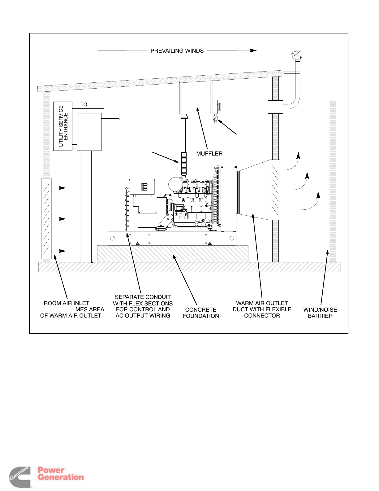
TO NON-EMERGENCY LOADS
Redistribution or publication of this document
by any means, is strictly prohibited.
TO EMERGENCY LOADS
PREVAILING WINDS
ENTRANCE
UTILITY SERVICE
SWITCH
TRANSFER
AUTOMATIC
AC FROM SET
CONTROL WIRING FROM SET
ROOM AIR INLET AT
LEAST 1-1/2 TIMES AREA
OF WARM AIR OUTLET
FLEXIBLE
TUBING
SEPARATE CONDUIT
WITH FLEX SECTIONS
FOR CONTROL AND
AC OUTPUT WIRING
MUFFLER
CONCRETE
FOUNDATION
CONDENSATE
DRAIN
WARM AIR OUTLET
DUCT WITH FLEXIBLE
CONNECTOR
WIND/NOISE
BARRIER
FIGURE 3-4. TYPICAL INDOOR EMERGENCY STANDBY INSTALLATION
3-4
Page 15

FUEL
Redistribution or publication of this document
by any means, is strictly prohibited.
WARNING
cause severe personal injury or death. Do not
smoke or allow any flame, spark, pilot light, arcproducing equipment, electrical switch or other
ignition source around fuel or fuel components,
or in areas sharing ventilation. Keep an appropriately sized type ABC fire extinguisher handy.
The fuel supply system must hold enough fuel to run
the generator set for the prescribed number or
hours before refueling (NFPA No. 110 Class designation). It must be free of leaks and contaminants.
See Figure 3-5 for a diagram of a typical fuel supply
system.
Diesel fuel is combustible and can
causes sludge that can clog fuel pumps and filters.
Although copper has been used for diesel fuel lines
for many years, black iron pipe is preferred. The
reason for this is that during long periods of standby
or of little use, diesel fuel can polymerize (thicken) in
copper tubing and clog fuel injectors.
Fuel supply tank construction, location, installation,
venting, piping, testing and inspection must comply
with all applicable codes.
A day tank must be provided if the fuel supply tank is
located above the engine fuel injectors or more than
3 meters (10 feet) below the fuel lift pump on the engine.
Approved flexible fuel hose must be used for fuel
supply and return connections at the engine to take
up generator set movement and vibration.
Diesel fuel lines should be black iron pipe. Galvanized pipe, fittings and tanks should not be used because the interaction between zinc and sulfur
A fuel transfer pump or float valve seat should be
protected from fuel tank debris by a prefilter or sediment bowl with a 100-120 mesh screen.
Note: Local regulations may require secondary
containment to prevent any leaking fuel from flowing into the sewer system or ground.
3-5
Page 16
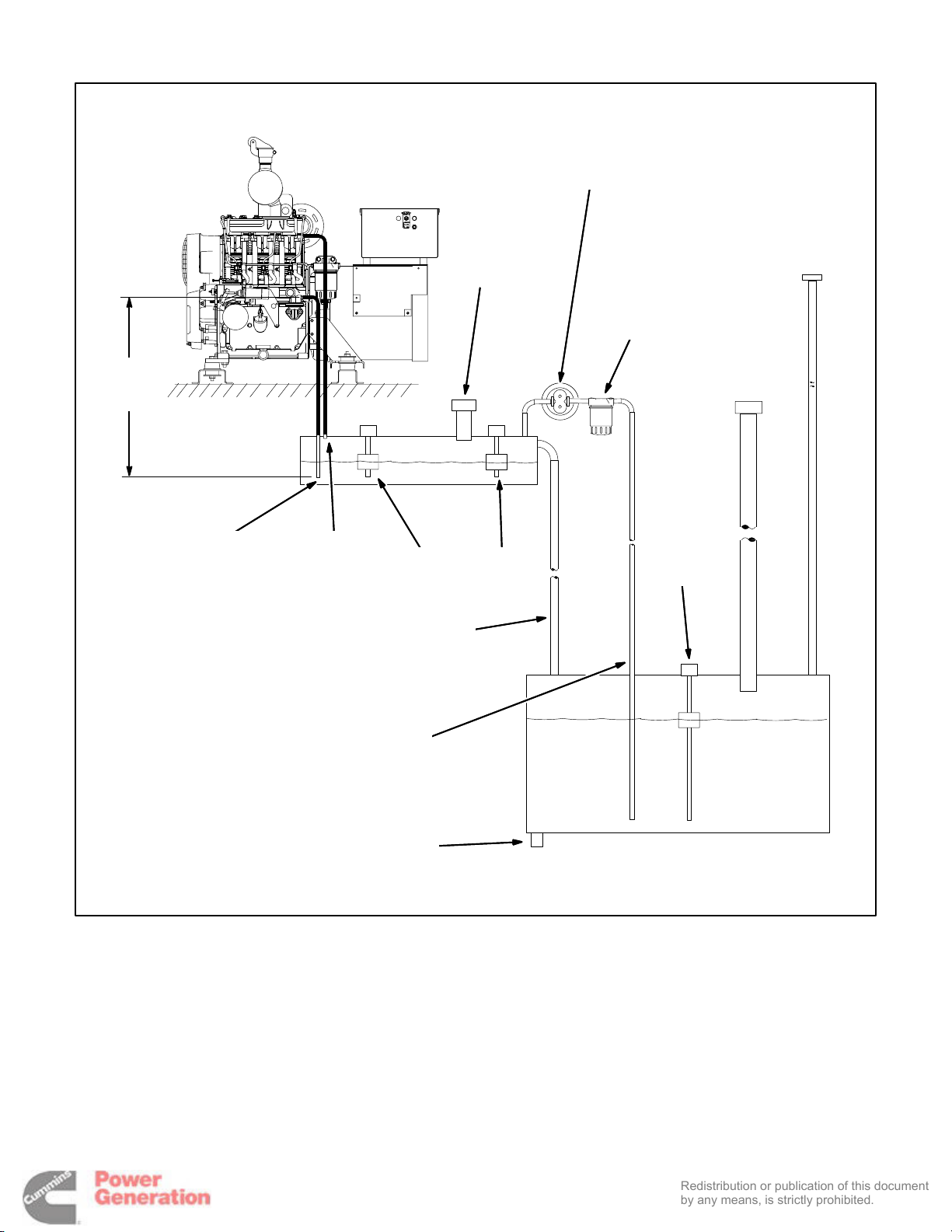
FUEL TRANSFER
Redistribution or publication of this document
by any means, is strictly prohibited.
PUMP
(LOAD SIDE OF
TRANSFER SWITCH)
3 METER
(10 FEET)
MAX
FUEL SUPPLY
(FLEXIBLE
FUEL HOSE)
FUEL RETURN
(FLEXIBLE
FUEL HOSE)
OVERFLOW LINE
(PIPE SIZE LARGER
THAN SUPPLY)
DAY TANK
LEVEL
GAUGE
VENTED
FILL CAP
FLOAT
SWITCH
PREFILTER
OR SEDIMENT
BOWL WITH
100-120 MESH
SCREEN
LEVEL
GAUGE
VENT
CAP
FILL
CAP
FUEL
SUPPLY
LINE
SEDIMENT
DRAIN
FUEL SUPPLY TANK
FIGURE 3-5. TYPICAL FUEL SUPPLY SYSTEM
3-6
Page 17
4. DC Control Wiring
Redistribution or publication of this document
by any means, is strictly prohibited.
CONTROL WIRING
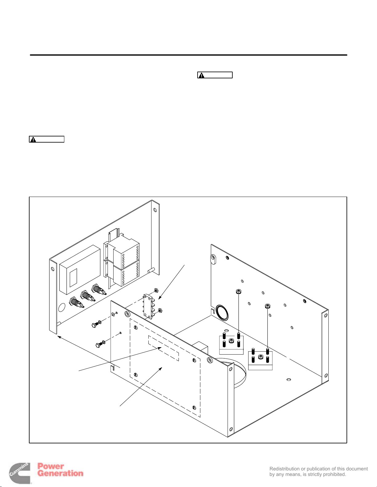
The generator set control box contains connection
points for remote control and monitor options.
These connection points are located inside of the
control box (Figure 4-1).
Use flexible conduit for all wiring connections to the
generator set.
CAUTION
for all customer connections to the control panel. Solid copper wire may break due to genset
vibration.
Stranded copper wire must be used
WARNING
HAZARDOUS VOLTAGE Touching
uninsulated high voltage parts inside the control box can result in severe personal injury or
death. Control wire installation must be done
with care to avoid touching uninsulated live
parts.
Stand on a clean dry wooden platform or clean
rubber insulating mat, make sure your clothing
and shoes are dry, remove jewelry and use tools
with insulated handles.
TB1
TB 26
BASE
BOARD
FIGURE 4-1. CONTROL BOX
4-1
Page 18

TB1 REMOTE MONITOR/CONTROL
Redistribution or publication of this document
by any means, is strictly prohibited.
CONNECTIONS
Customer monitor/control connections are attached to terminal block TB1 (Figure 4-1). Optional
equipment, such as sensing devices used to monitor genset operation, remote start/stop switches,
etc. are attached to TB1. Refer to Customer Connections diagram in Section 8.
Available options will vary between PCC1301 control
models (PCC with or without display).
TB1 Wiring
CAUTION
a separate metal conduit from AC power cables
to avoid inducing currents that could cause
problems within the control.
Digital Connections: Connection points, other
than relayed outputs and network are considered
digital connections to terminal strip TB1. The type/
gauge wire to use for these connections are:
Always run control circuit wiring in
• Less than 1000 feet (305m), use 20 gauge
stranded copper wire.
• 1000 to 2000 feet (305 to 610m), use 18 gauge
stranded copper wire.
Relay Connections: Due to the wide variety of devices that can be attached to the relay outputs of
TB1, the electrical contractor must determine the
gauge of the stranded copper wire that is used at
this installation site.
TB1 Customer Inputs
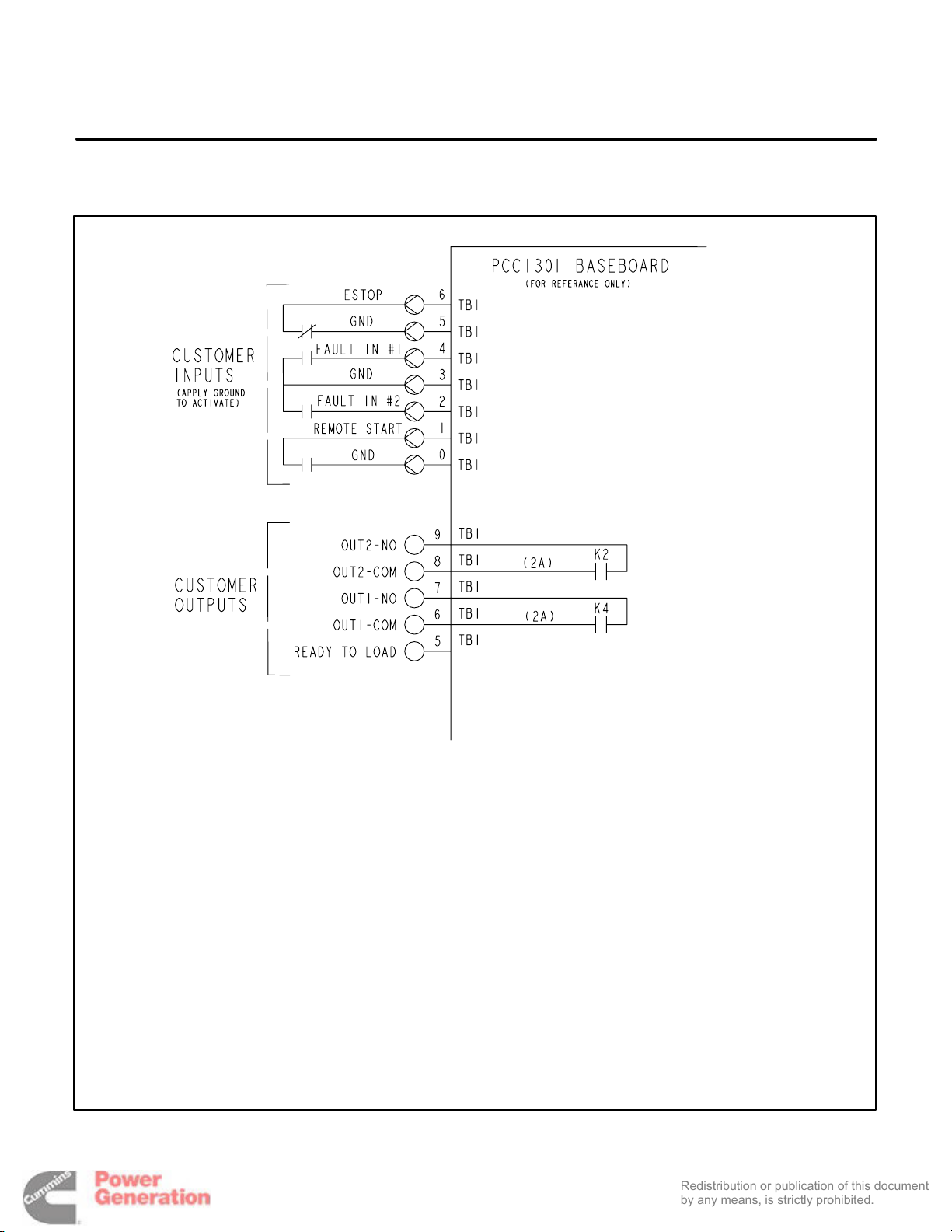
Refer to Page 8-1 for typical connections to TB1.
Remote Start: When the control is in Auto/Remote
mode, grounding this input initiates the engine
cranking and start sequence. This circuit must be
opened to permit resetting a shutdown condition
with the Reset input. (The remote stop is actually
the removal of the remote start signal to the control.)
Remote Emergency Stop: Opening this input
causes an immediate shutdown. Emergency stop
must be reset at the front panel.
The nature of the fault is an optional customer
selection. Example inputs: Low Coolant Level, Low
Fuel Pressure, Ground Fault, etc.
Each of the two fault functions can be programmed
as follows:
• Status, Warning or Shutdown. Default = Warning.
• Enter a brief description of the event (up to 32
characters).
The InPower service tool or access to the Setup Submenus is required to modify the customer fault inputs. Contact an authorized service center for assistance.
TB1 Customer Outputs
Refer to Page 8-1 for typical connections to TB1.
Customer Outputs 1 and 2: One set of normally
open (NO) contacts, rated for 2 amps at 30 VDC for
each of the two output signals. The relays can be
used to control small devices and indicator lamps.
The nature of the customer output signal (contacts
closed) is an optional customer selection. Example
outputs: Genset running (event), common warning,
common shutdown, etc. (Refer to Operator’s manual for warning and shutdown code listing and the
Service manual for event code listing.)
Each relay can be independently programmed to
energize by entering a code number (0 through 255,
default = 0) for the desired event.
The InPower service tool or access to the Setup Submenus is required to modify the customer outputs.
Contact an authorized service center for assistance.
Ready To Load Signal (Generator Set Running):
B+ signal out when the generator set has reached
90 percent of rated speed and voltage.
SWITCHED B+
Switched B+ (T26) has six terminals located in the
control box and is fused at 20 amps.
Customer Fault Inputs 1 and 2: Grounding any
one of these inputs activates the corresponding
warning or shutdown sequence.
External sensing equipment must be connected to
the designated digital input.
UNIVERSAL ANNUNCIATOR
The optional universal annunciator (300-5929) provides for remote monitoring of the power system.
Refer to its operators manual for connections.
4-2
Page 19
I/O MODULE
Redistribution or publication of this document
by any means, is strictly prohibited.
The optional I/O module provides additional customer inputs and outputs for control and monitoring
of the power system. Up to sixteen relay outputs
and twelve discrete analog inputs are available
when the control contains both the Base I/O Module (AUX101) and the Expansion I/O Module
(AUX102). Refer to Instruction Sheet C693 for I/O
module configuration/wiring information.
BASE BOARD
K10
K11
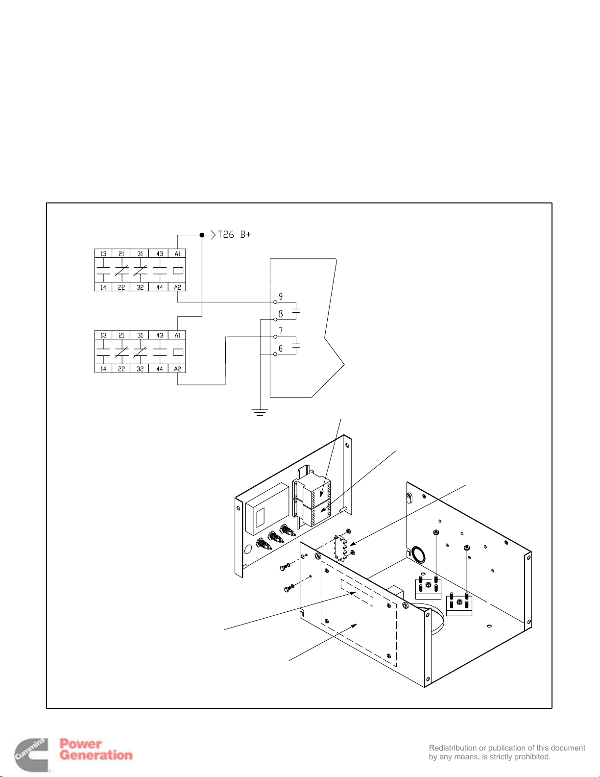
RUN RELAYS (K10, K11)
The optional run relays are mounted inside the control box (Figure 4-2). They are used to control auxiliary equipment such as fans, pumps and motorized
air dampers. The run relays are energized when the
generator set control receives a start signal.
The contacts are rated:
• 20 amps resistive @ 30VDC
• 15 amps inductive @ 30VDC
TB1
TB1
K10
K11
T26 (SW B+)
BASE
BOARD
FIGURE 4-2. OPTIONAL RUN RELAYS (K10, K11)
4-3
Page 20
BATTERIES
Redistribution or publication of this document
by any means, is strictly prohibited.
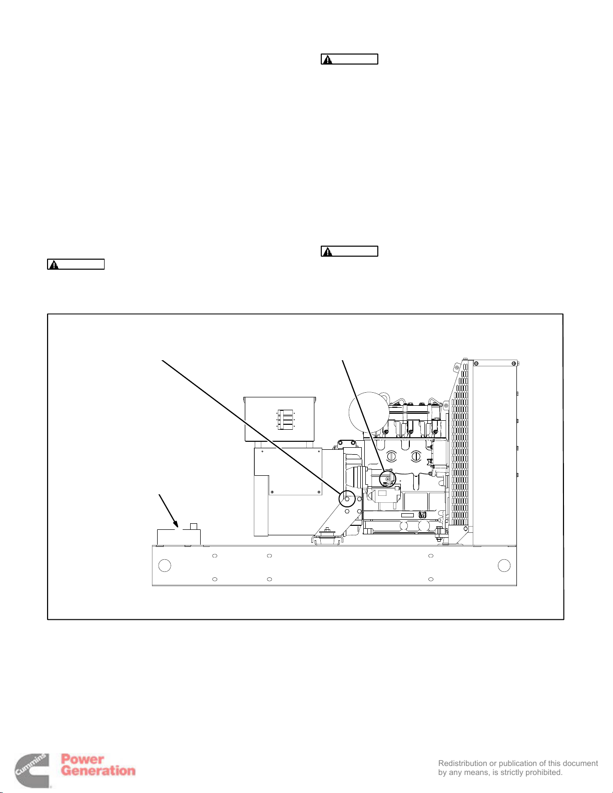
The generator set has a 12 VDC, negative-ground
control and starting system. See Figure 4-3 for battery cable connections and Specifications for mini-
mum battery requirements.
The engine is equipped with a 45 amp battery
charging alternator to supply the control loads and
restore cranking current. Emergency standby applications will require a battery charger powered by
the normal AC power supply. Check the local codes
for emergency standby requirements.
The generator set is provided with battery cables
and the skid-base has a built-in battery rack.
WARNING
vere personal injury or death. Push the control
panel switch to OFF before connecting the battery cables.
Accidental starting can cause se-
WARNING
Arcing can ignite battery gases and
cause severe personal injury and can cause
voltage spikes that can damage generator set
control circuits. To reduce arcing:
Always disconnect a battery charger from its
AC source before disconnecting the battery
cables.
Always disconnect the negative (–) cable first
and reconnect it last. (This prevents arcing if the
tool on the positive terminal touches grounded
metal.)
CAUTION
The battery must be of a type with
barbed vent hose fittings for its cells. The vent
lines must be routed away from the generator
end bell (air inlet) to prevent battery gases from
entering the generator and causing corrosion.
NEGATIVE (–) CABLE
CONNECTION
SEALED TYPE BATTERY TO
PREVENT GASES FROM EN-
TERING GENERATOR AND
CAUSING CORROSION
POSITIVE (+) CABLE CONNECTION
(STARTER SOLENOID TERMINAL)
FIGURE 4-3. BATTERY CONNECTIONS
4-4
Page 21
5. AC Electrical Connections
Redistribution or publication of this document
by any means, is strictly prohibited.
GENERAL
This section provides the procedure that is used to
connect the AC electrical system of the genset.
Before making any AC electrical connections, make
certain the generator set cannot be accidentally
started. Place the control panel run switch in the
OFF position. Turn off or remove AC power from the
battery charger and then remove the negative (–)
battery cable from the set starting battery.
WARNING
can cause severe personal injury or death. Arcing at battery terminals, light switch or other
equipment, flame, pilot lights and sparks can ignite battery gas. Do not smoke, or switch
trouble light ON or OFF near battery. Discharge
static electricity from body before touching batteries by first touching a grounded metal surface.
Ventilate battery area before working on or near
battery—Wear goggles—Stop genset and disconnect charger before disconnecting battery
cables—Disconnect negative (–) cable first and
reconnect last.
CAUTION
source before disconnecting battery cables.
Otherwise, disconnecting cables can result in
voltage spikes damaging to DC control circuits
of the set.
WARNING
set can cause severe personal injury or death.
Prevent accidental starting by disconnecting
the negative (–) cable from the battery terminal.
Ignition of explosive battery gases
Disconnect battery charger from AC
Accidental starting of the generator
WARNING
this section should be done only by persons
trained and experienced in electrical maintenance. Improper procedures may result in property damage, bodily injury or death.
Connecting the genset AC electrical system involves:
Each of the operations described in
• Installation of transfer switch
• Generator output voltage selection
• Load cable connection
• Standard and optional AC equipment connec-
tions (e.g., control box heater, coolant heater,
etc.).
Local regulations often require that wiring connections be made by a licensed electrician, and that the
installation be inspected and approved before operation. All connections, wire sizes, materials used,
etc. must conform to the requirements of electrical
codes in effect at the installation site.
WARNING
electrical hazard, resulting in severe personal
injury or death and/or property and equipment
damage.
Before starting the genset, check to make sure that
all electrical connections are secure, and that all
wiring is complete. Replace and secure any access
panels that have been removed during installation.
Check that the load cables from the genset are
properly connected.
WARNING
cause electrocution or property damage. Do not
connect to any building electrical system except through an approved device and after
building main switch is opened.
Improper wiring can cause a fire or
Backfeed to utility system can
5-1
Page 22
TRANSFER SWITCH
Redistribution or publication of this document
by any means, is strictly prohibited.
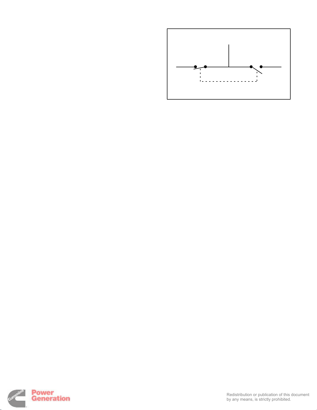
If the installation is for standby service, a transfer
switch must be used for switching the load from the
normal power source to the genset (see Figure 5-1).
Follow the installation instructions provided with the
transfer switch when connecting the load and control wiring.
LOAD
NORMAL
SOURCE
FIGURE 5-1. TYPICAL LOAD TRANSFER
FUNCTION
GENSET
5-2
Page 23

AC WIRING
Redistribution or publication of this document
by any means, is strictly prohibited.
Generator Voltage Connections
The available generator output voltages and maximum current ratings are specified on the generator
set nameplate. Line-to-neutral voltage is always the
lower voltage shown and line-to-line voltage is the
higher rating.
Some generator sets are capable of producing a
wide range of voltages and connection configurations, others have specific limited capabilities. Refer to wiring diagram and generator voltages (from
the nameplate) when reviewing the voltage connection information and use the wiring diagram supplied with your generator set when actually performing load connections.
These generators can be configured to the nameplate voltages as shown on the Reconnection Diagram decal, attached to the backside of the control
box cover. Many of the voltages listed will require
reconfiguration of the generator output leads on the
connection terminal block. This reconfiguration
must only be done by service personnel that are
trained and experienced to perform electrical installation. The generator set was adjusted to produce a
specified voltage during production verification testing prior to shipment. The installer must always
check the stator lead terminal block connections
and perform any necessary reconnect to obtain the
voltage required.
CAUTION
Reconfiguring generator sets to
higher voltages can exceed the voltage capability of the specific generator windings and damage the generator and also decrease line current, rendering line circuit breakers too large.
Consult with your distributor before performing
reconnection for a different voltage.
CAUTION
Reconfiguring generator sets to
lower voltages can reduce generator set ratings, and also increase line current, rendering
line circuit breakers too small. Consult with
your distributor before performing reconnection for a different voltage.
5-3
Page 24
Load Connections
Redistribution or publication of this document
by any means, is strictly prohibited.
Flexible conduit and stranded conductors must be
used for connections to take up movement of the
generator set.
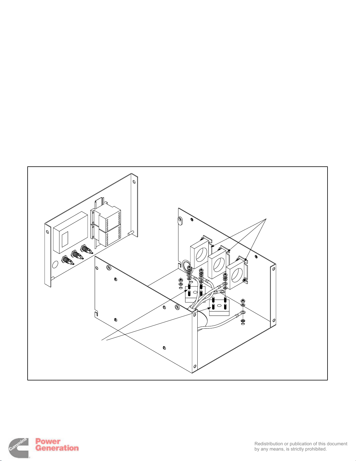
All loads are connected to the generator by bolting
stranded load wires to the appropriate terminals on
the generator reconnection terminal block or circuit
breaker lugs. The terminals are marked U, V, W and
N to indicate the line and neutral connections. (Reference: U, V, and W correspond with L1, L2 and L3;
and N with L0 respectively).
Load Balancing
When connecting loads to the generator set, bal-
ance the loads so the current flow from each line terminal (L1, L2 and L3) is about the same. This is especially important if both single phase and three
phase loads are connected. Any combination of
single phase and three phase loading can be used
as long as each line current is about the same, within 10 percent of median value, and no line current
exceeds the nameplate rating of the generator.
Check the current flow from each line after connections by observing the control panel ammeter.
Current Transformers (Optional)
The optional current transformers (CT’s) are used
to display genset load in kVA and alternator amperage. Refer to the Reconnection Diagram for routing
leads through the CTs.
AC TERMINALS
CURRENT
TRANSFORMERS
FIGURE 5-2. AC OUTPUT BOX
5-4
Page 25
Grounding
Redistribution or publication of this document
by any means, is strictly prohibited.
The following is a brief description of system and
equipment grounding of permanently installed AC
generators within a facility wiring system. It is important to follow the requirements of the local electrical
code.
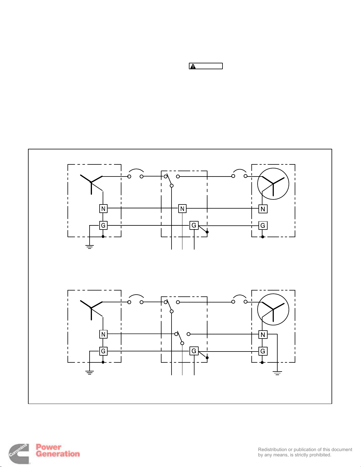
Figure 5-3 illustrates typical system grounding for a
3-pole and a 4-pole automatic transfer switch
(ATS). In the 3-pole ATS, note that the generator
neutral is connected to the ATS and is NOT bonded
to ground at the generator. In the 4-pole ATS system, a grounding electrode conductor and a bonding jumper are used to connect the generator neutral to ground.
Make sure the genset is grounded to earth in one
location only. Use the ground lug provided in the
power output box.
WARNING
Electric current can cause severe
personal injury or death. Bonding and grounding must be done properly. All metallic parts
that could become energized under abnormal
conditions must be properly grounded.
Typical requirements for bonding and grounding
are given in the National Electrical Code, Article
250. All connections, wire sizes, etc. must conform
to the requirements of the electrical codes in effect
at the installation site.
SERVICE ENTRANCE
THREE-PHASE, FOUR-WIRE UTILITY, THREE-POLE ATS
SERVICE ENTRANCE
GENERATOR SET
3-POLE ATS
LOAD
GENERATOR SET
4-POLE ATS
FIGURE 5-3. TYPICAL SYSTEM GROUNDING ONE-LINE DIAGRAMS
LOAD
THREE-PHASE, FOUR-WIRE UTILITY, FOUR-POLE ATS
5-5
Page 26

CONTROL HEATER (OPTIONAL)
Redistribution or publication of this document
by any means, is strictly prohibited.
A control heater (Figure 5-4) provides a means of
humidity / temperature control of the control box interior. It protects the components when the generator set is subjected to varying ambient air conditions
during extended periods of non-use.
The heater is equipped with a power cord that terminates with a 120V or 240V NEMA plug.
COOLANT HEATER (OPTIONAL)
Connect the heater to a source of power that will be
on during the time the generator set is not running.
Be sure the voltage rating is correct for the heater
element rating.
GENERATOR HEATER (OPTIONAL)
A generator heater is used to help keep the generator free of condensation when the generator set is
not running. During cool and humid conditions, condensation may form within a generator, creating
flashing and shock hazards.
A coolant heater is used to keep the engine coolant
warm when the engine is shut down. It heats and circulates the coolant within the engine. This reduces
startup time and lessens engine wear caused by
cold starts. It is electrically operated and thermostatically controlled.
WARNING
The coolant heater must not be operated while the cooling system is empty or
damage to the heater will occur.
The heater is equipped with a power cord that terminates with a 120V or 240V NEMA plug.
WARNING
Water or moisture inside a generator increases the possibility of flashing and
electrical shock, which can cause equipment
damage and severe personal injury or death. Do
not use a generator which is not dry inside and
out.
The heater is equipped with a power cord that terminates with a 120V NEMA plug.
Connect the heater to a source of power that will be
on during the time the generator set is not running.
5-6
Page 27
6. Prestart Preparation
Redistribution or publication of this document
by any means, is strictly prohibited.
GENERAL
Before attempting the initial start of the generator
set, be sure to complete the Installation Checklist in
Section 7.
INPOWER SERVICE TOOL
GENERAL INFORMATION
InPower is a PC based service tool for the PowerCommand
• Make adjustments to the controls trims and set-
• Perform diagnostics and monitoring.
• Create a capture file of the control’s trims and
• Update control calibrations (InPower PRO ver-
Refer to INPOWER User’s Guide for specifics.
tings.
settings.
sion).
1301 Control (PCC). Use InPower to:
InPower Adjust Mode
The adjustment feature allows you to make adjustments to genset parameters, calibrations and settings. There are several groups of adjustment parameters; note that not all gensets will have the
same adjustments available.
InPower Capture File Description
InPower provides a method of extracting (capturing) a device’s parameter values. Capturing saves
device information in a file that is identified with a
.CAP extension.
Capture files are used to store a copy of the genset’s parameter values. During genset installation,
it is suggested that a capture file be made before
and after changes are made to the genset operating
parameters. This information can be a very useful
when troubleshooting the genset (determine if parameters/settings have been modified after installation) and when replacement of the Base board is
necessary. The capture file can be used as a template to write the previous settings to the new Base
board software.
ELECTRICAL SYSTEM
Verify all electrical connections are secure and all
wiring is complete and inspected. Replace and secure any access panels that may have been removed during installation.
Battery Connections
WARNING
set can cause severe personal injury or death.
Make sure that the PCC is in the OFF mode before connecting the battery cables.
Starting the unit requires a 12 volt battery. Connect
positive battery cable before connecting negative
battery cable to prevent arcing.
Service the batteries as necessary. If an automatic
transfer switch is installed without a built-in charge
circuit, connect a separate battery charger. Proper
selection and maintenance of batteries and battery
chargers is essential for system reliability.
WARNING
can cause severe personal injury or death. Always connect negative (–) battery cable last to
prevent arcing.
WARNING
ing on or near battery. Arcing at battery terminals, light switch or other equipment, flame, pilot lights and sparks can ignite battery gas. Do
not smoke, or switch trouble light ON or OFF
near battery. Discharge static electricity from
body before touching batteries by first touching
a grounded metal surface.
Accidental starting of the generator
Ignition of explosive battery gases
Ventilate battery area before work-
6-1
Page 28

PCC OPTIONS PRESTART CHECKS
Redistribution or publication of this document
by any means, is strictly prohibited.
Adjusting Values/Parameters
All generator set configuration options are set at the
factory except for site related options, (e.g., Start/
Stop Time Delays, Cycle Crank, Customer Fault 1
and 2, etc.
If the PCC graphical display option is not provided,
the InPower service tool will be required to adjust all
site related options.
Adjustment of these options are divided into two
categories within the menu driven system. These
two categories are Setup and Screen Adjust.
The Setup menus are intended for qualified service
personnel only and require a password to modify
these submenus (refer to Service manual). The
Screen Adjust menu is intended for service personnel and site personnel.
SCREEN ADJUST MENU
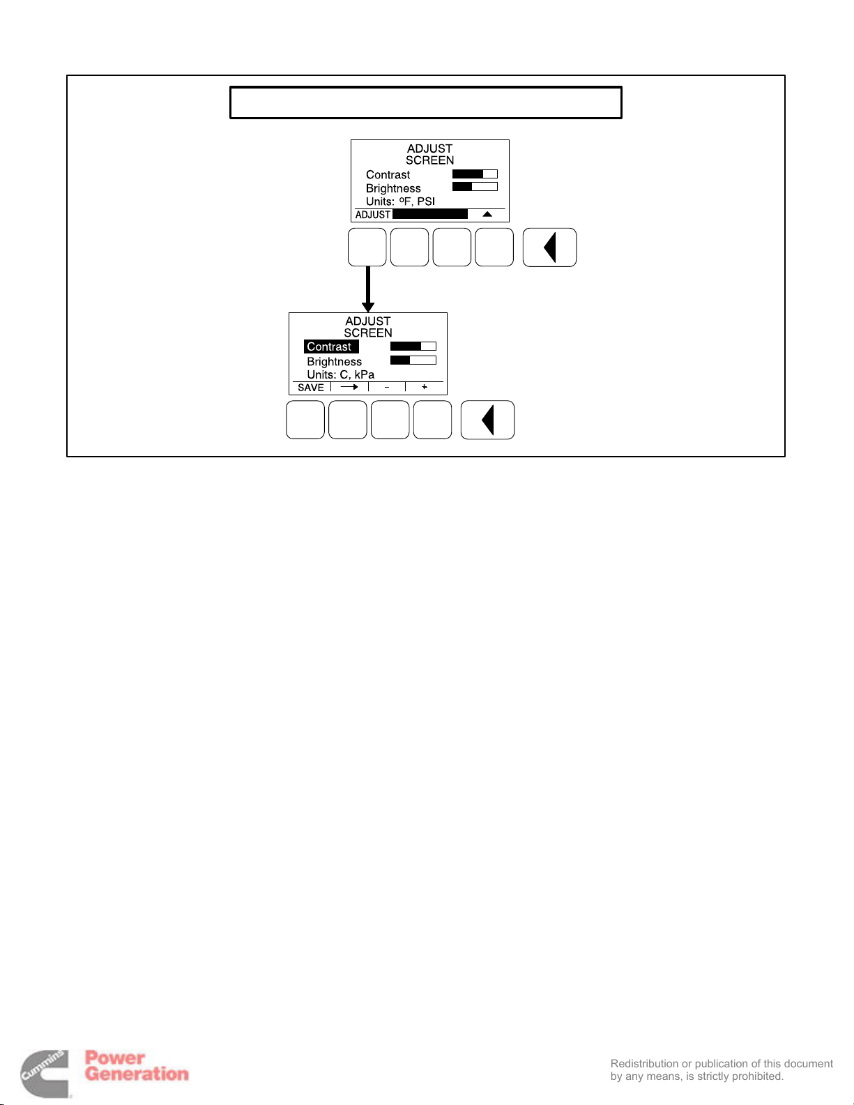
Figure 6-1 shows a block representation of the
Screen Adjust menu. The Screen Adjust menu is
displayed when the (3) button is pressed in the first
Service Menu.
1. Press the ADJUST selection button to select
the first parameter or value to be changed.
2. Press the + or – selection buttons to adjust val-
ues or select parameters.
3. Press the arrow selection button
to navigate to the next or previous adjustable value or
parameter.
4. After adjusting values/selecting parameters,
press the SAVE button to save your settings.
NOTE: If the Previous Menu button
is
pressed before pressing the SAVE button, the changes are not saved.
5. Press the
button to return to the Service
Menu.
Screen Adjust Menu
This menu allows for adjusting the screen’s contrast
and brightness and for selecting the units of measurement (SAE or SI) to be displayed.
• Contrast and Brightness: Press the + or –
selection buttons to adjust the screen’s contrast and brightness. Changing the brightness setting also affects the brightness of the
LEDs on the control panel.
From any of the Operator menus, simultaneously
press the
onds to display the first Service menu.
and selection buttons for two sec-
• Units: Press the + or – selection buttons to
select SAE (_F, PSI) or SI (C, kPa) units of
measurement to be displayed.
6-2
Page 29
SCREEN ADJUST MENU
Redistribution or publication of this document
by any means, is strictly prohibited.
FIGURE 6-1. SCREEN ADJUST MENU
6-3
Page 30

STARTING
Redistribution or publication of this document
by any means, is strictly prohibited.
Refer to the generator set Operator’s manual for important safety precautions and recommended procedures for starting the genset and verifying proper
operation. Start the generator set and verify all engine and generator menus are displaying the correct values.
6-4
Page 31

7. Installation Checklist
Redistribution or publication of this document
by any means, is strictly prohibited.
GENERAL
Generator set wattage capacity is sufficient to handle maximum anticipated load.
j
j At least 3 feet of clearance (or greater for housing door) is provided around entire generator set for servic-
ing and ventilation.
j Generator set is located in an area not subject to flooding.
j All operating personnel have read and are familiar with Operator’s manual.
j All operators have been thoroughly briefed on preventive maintenance procedures.
j All operators have read and understand all Important Safety Instructions in Operator’s manual.
GENERATOR SET SUPPORT
Floor, roof or earth on which the generator set rests is strong enough and will not allow shifting or move-
j
ment. Observe local codes on soil bearing capacity due to freezing and thawing.
j Generator set is properly supported and retained to approved base.
j Supporting base is large enough and is of non-combustible material – extends 6-inches all around set.
COOLING AIR FLOW
Generator set air inlet is faced into direction of strongest, prevailing winds.
j
j Air inlet openings are unrestricted and at least 1–1/2 times larger than air outlet area.
j Cooling air outlet is on downwind side of building (if not, wind barrier is constructed).
j Proper ducting material (sheet metal, canvas) is used between radiator and air outlet.
DIESEL FUEL SYSTEM
Fuel tanks meet or exceed all Local, State or National codes.
j
j Fuel lines are properly installed, supported and protected against damage.
j Approved flexible fuel line is installed between main fuel supply line and generator set’s fuel system, near
the generator set, to protect the fuel system from damage caused by vibration, expansion and contraction.
j Strainer or fuel screen (100 to 120 mesh) is installed in the fuel supply line to protect the fuel lift pump, day
tank transfer pump or float valve seat from fuel supply tank debris.
j Automatic fuel supply line shutoff valves are installed to prevent fuel flow in case of leaks.
j No shutoff valves are installed on engine fuel return line.
j External fuel pumps are connected and operational at all times (generator set started or shut down).
j Fuel system is properly primed.
j No fuel leaks are found in supply line or engine fuel system.
7-1
Page 32

EXHAUST SYSTEM
Redistribution or publication of this document
by any means, is strictly prohibited.
Operators are thoroughly briefed on the dangers of carbon monoxide gas.
j
j Areas around set are well ventilated. No possibility of exhaust fumes entering building doors, windows, or
intake fans.
j Exhaust gases are piped safely out-of-doors and away from building.
j The correct length of approved rigid pipe is connected to the generator set flexible pipe using approved
securing methods with no weight resting on engine exhaust components. There are no bends in flex section.
j Condensation drain is provided in lowest section of exhaust piping.
j Exhaust piping is insulated to guard against burns to personnel.
j Exhaust piping passing through walls or ceilings have approved fire-proof materials and are in com-
pliance with all codes.
j Exhaust piping is large enough in diameter to prevent excessive back pressure on engine.
AC AND DC WIRING
Wire sizes, insulation, conduits and connection methods all meet applicable codes.
j
j AC and DC wires are separated in their own conduit to prevent electrical induction.
j All load, line and generator connections are proper and correct.
j Flexible conduit between generator set and building or surrounding structure.
GENERATOR SET PRESTART
Generator set engine is properly serviced with oil and coolant.
j
j Batteries are properly installed, serviced and charged.
j Battery charger and engine coolant heater are connected and operational.
j All generator set covers and safety shields are installed properly.
j All fuel and coolant shutoff valves are operational.
j Created control capture file of the genset’s parameter values before and after modifications.
7-2
Page 33
8. Wiring Diagrams
Redistribution or publication of this document
by any means, is strictly prohibited.
NOTES:
1. TORQUE TERMINALS TO 4.4 IN/LBS (0.5 Nm).
2. WIRE SIZE, 30–AWG (0.14–2.5MM) (TB1).
3. WIRE TYPE, USE 60°C RATED MINIMUM. COPPER WIRE (TB1).
4. TERMINAL SCREWS ARE SLOTTED (0.6MN).
5. USE FLAT–BLADED SCREWDRIVER WITH 2.5MN BLADE.
6. STRIP WIRE LENGTH TO 6.0MN.
7. FAULT IN #1 USED FOR OPTIONAL LOW COOLANT LEVEL.
8. FAULT IN #2 USED FOR OPTIONAL FUEL FAULT.
CUSTOMER CONNECTION DIAGRAM
8-1
Page 34

THIS PAGE LEFT INTENTIONALLY BLANK
Redistribution or publication of this document
by any means, is strictly prohibited.
8-2
Page 35

Redistribution or publication of this document
by any means, is strictly prohibited.
Page 36

Cummins Power Generation
Redistribution or publication of this document
by any means, is strictly prohibited.
1400 73rd Avenue N.E.
Minneapolis, MN 55432
1-800-888-6626
763-574-5000 International Use
Fax: 763-528-7229
Cummins is a registered trademark of Cummins Inc.
 Loading...