

Culligan M2 Series, M2-4, M2-2, M2-5, M2-6 Installation, Operation And Service Instructions
...
CULLIGAN
Cat. No. 01023095
Rev. C 05/03/13
DCO # 013581
Installation,
Operation and
Service
Instructions
®
Series M2
Reverse Osmosis Water Treatment
Systems
Models from 2011
Firmware Version
©2013 Culligan International Com pa ny
Attention Culligan Customer:
Your local independently operated Culligan dealer employs trained service and maintenance personnel who are experienced in the installation, function and repair of Culligan equipment. This publication is written specifically for these
individuals and is intended for their use.
We encourage Culligan users to learn about Culligan products, but we believe that product knowledge is best obtained by
consulting with your Culligan dealer. Untrained individuals who use this manual assume the risk of any resulting property
damage or personal injury.
NOTICE Please send any suggestions for improving this manual to productmanuals@culligan.com.
WARNING! Electrical shock hazard! Prior to servicing equipment, disconnect power supply to
prevent electrical shock.
WARNING! If incorrectly installed, operated, or maintained, this product can cause severe injury.
Those who install, operate, or maintain this product should be trained in its proper
use, warned of its dangers, and should read the entire manual before attempting to
install, operate, or maintain this product. Failure to comply with any warning or
caution that results in any damage will void the warranty.
CAUTION! This product is not to be used by children or persons with reduced physical, sensory
or mental capabilities, or lack of experience or knowledge, unless they have been
given supervision or instruction.
CAUTION! Children should be instructed not to play with this appliance.
WARNING! This device complies with Part 15 of the FCC rules subject to the two following
conditions: 1) This device may not cause harmful interference, and 2) This device
must accept all interference received, including interference that may cause undesired
operation.
This equipment complies with Part 15 of the FCC rules. Any changes or modifications not expressly approved by the
manufacturer could void the user’s authority to operate the equipment. Changes or modifications not expressly approved
by the party responsible for compliance could void the user’s authority to operate the equipment.
CAUTION! To reduce the risk of fire, use only No. 26 AWG or larger telecommunications line
cord.
NOTE This system is not intended for use with water that is microbiologically unsafe or of unknown quality
without adequate disinfection either before or after the system.
NOTE Check with your public works department for applicable local plumbing and sanitation codes. Follow
local codes if they differ from the standards used in this manual. To ensure proper and efficient operation of the Culligan equipment to your full satisfaction, carefully follow the instructions in this manual.
Products manufactured and marketed by Culligan International Company (Culligan) and its affiliates are protected by
patents issued or pending in the United States and other countries. Culligan reserves the right to change the specifications referred to in this literature at any time without prior notice. Culligan, Aqua-Sensor, Tripl-Hull, and SoftMinder are
trademarks of Culligan International Company or its affiliates.
Culligan International Company
9399 West Higgins Road, Suite 1100
Rosemont, Illinois 60018
1-847-430-2800
www.culliganmatrixsolutions.com
Culligan®
Installation
and
Operation
Instructions
Series M2
Reverse Osmosis Water
Treatment Systems
Models From 2011
Contents
Introduction ........................................................................ 1
Features ............................................................................ 2
Series M2 Specifications ................................................... 5
Unit Configurations ............................................................ 6
RO Installation ................................................................... 7
Electrical Installation ........................................................ 12
GROC Board Layout ....................................................... 13
GROC Programming ....................................................... 15
Menu and Key Navigation ............................................... 16
First Time Set Up ............................................................. 17
Basic Operation ............................................................... 20
Setup ............................................................................... 21
Accessories ..................................................................... 28
Initial Startup.................................................................... 55
System Operating Information ......................................... 58
Service and Maintenance ................................................ 60
Flow Diagram ................................................................. 71
GBE RO Controller Wiring ............................................... 72
M2 RO Parts Diagrams and Lists .................................... 73
Appendix A Series M2 International ............................. 87
Appendix B Basic Principles ...................................... 102
Appendix C GBE RO Controller Menu Structure ....... 104
Appendix D Data Port Output..................................... 108
Appendix E Quick Programming Guide ..................... 112
Appendix F Programming Log ................................... 116
Index .............................................................................. 11 7
Cat. No. 01023095
i

This page intentionally left blank.
ii Culligan® Series M2 Reverse Osmosis
ii Cat. No. 01023095
Introduction
Read this Manual First
Before you operate the Culligan® Series M2 reverse osmosis systems, read this manual to become familiar with the
device and its capabilities.
®
Culligan
manual contains important information about the unit, including information needed for installation, operating, and maintenance procedures. A troubleshooting section provides a guide for quick and accurate problem solving.
In order for the water treatment system to continue to provide high quality water, you must develop a thorough understanding of the system and its operation. Review this manual before making any attempt to install, operate, or service
the system. Installation or maintenance done on this system by an untrained service person can cause major damage to
equipment or property damage.
About this Manual
This manual:
This publication is based on information available when approved for printing. Continuing design refinements could cause
changes that may not be included in this publication.
Series M2 reverse osmosis systems are designed to meet the needs of applications for high quality water. This
• Familiarizes the operator with the equipment
• Explains installation and setup procedures
• Provides basic programming information
• Explains the various modes of operation
• Gives specifications and troubleshooting information
Safe Practices
Throughout this manual there are paragraphs set off by special headings.
Notice
Notice is used to emphasize installation, operation or maintenance information which is important, but does not present
any hazard. For example,
NOTICE The nipple must extend no more than 1 inch above the cover plate.
Caution
Caution is used when failure to follow directions could result in damage to equipment or property. For example,
CAUTION! Disassembly while under water pressure can result in flooding.
Warning
Warning is used to indicate a hazard which could cause injury or death if ignored. For example,
WARNING! Electrical shock hazard! Unplug the unit before removing the timer mechanism or
cover plates!
The CAUTION and WARNING paragraphs are not meant to cover all possible conditions and situations that may occur. It
must be understood that common sense, caution, and careful attention are conditions which cannot be built into the equipment. These MUST be supplied by the personnel installing, operating, or maintaining the system.
Be sure to check and follow the applicable plumbing codes and ordinances when installing this equipment. Local codes
may prohibit the discharge of acid or caustic solutions to drain. An extra solution tank should be used to neutralize the
solution before discharging to drain.
Use protective clothing and proper face or eye protection equipment when handling chemicals or power tools.
Cat. No. 01023095
Introduction 1

Features
The M2 Series Reverse Osmosis systems are the direct result of Culligan’s long time experience in membrane applications around the world. From process water for any size business to treating water for an entire city, Culligan has the
knowledge and the range of products you need to get the job done.
The M2 reverse osmosis system is sized to serve many small-to-medium-sized applications that require high-quality
reverse osmosis water. It is designed with the flexibility to closely match your treatment requirements from 2.8 to 6.9 gallons per minute (4,000 to 10,000 gallons per day). A rich standard feature set with multiple options can satisfy virtually any
application. Select the right size and choose any options needed to complete your system.
Key Product Features
• Simple System Integration
• Global Product Platform
• Flexible Configurations
• Quick Delivery/Easy Installation
• Exclusive Culligan Advanced Electronics
• Historical Operating Data
• Alarm Recognitions
• US Standard and Metric Readings
• Remote Monitoring Options
• Telemetry Options
• Real Time Clock: Tracks date and time has five-year battery back up.
• TDS Probe: TDS probe measures product water quality.
• Remote Alarm Output Connection (Optional): Provides either a N.O. or N.C. Dry Contacts. This feature can be
used to activate an alarm or programmed into a customers (DCS) building alarm system.
GBE RO Controller (GROC) Features
System Computes Normalized Flow
The system computes normalized flow and can be set to trigger an alarm if the normalized flow drops below a specified
limit.
Power Up Mode
The system can be configured to either go to standby mode or to automatically return to making RO water in the event of
power loss and restoration.
Storage Tank and Pressure Logic
The system has the ability to monitor high and low level switches in an atmospheric storage tank and a pressure switch in
a pressurized storage tank to automatically put the system into standby mode when the tank is full.
Pretreatment Lockout
Allows for single softener or filter pretreatment that can be set to go into regeneration or backwash cycle at low water use
periods and have the RO in standby until cycle is completed. RO product water tank would need to be sized correctly
based on flow demand if continuous RO product water is required.
GBE Historical Data
The GBE RO Controller stores basic performance data over the lifetime of the membranes as an aid to optimizing RO
performance and determining when the membranes need to be cleaned or replaced.
Flush Options
The system offers five different membrane flush modes to improve performance and extend membrane life.
2 Culligan® Series M2 Reverse Osmosis
2 Cat. No. 01023095

Target TDS
The RO system keeps track of the average product water TDS whenever the RO system is operating, mixing lower quality
water with product water to meet the average product water TDS.
Communications via Modem
An optional modem and monitoring service can be used to remotely monitor the RO performance over time. This service
can also be used to alert the customer and the Culligan dealer in the event that an alarm or error condition occurs.
Wireless Remote Communication
An optional wireless remote can display the current operational status and performance statistics up to 200 feet from the
G1 RO system.
PLC Outputs Available
The GBE Controller collects data once per minute and then streams the data to a customer-owned PLC for data collection
or monitoring. Customer would have to write code to take text information and convert the data for their data collection
system. For more information, see Culligan P/N 01021512 Advanced Communication Manual.
This data, once converted from a text stream, can easily be imported to an excel spreadsheet and the data logged can
then be graphed and trended.
Multi-Unit RO
The GBE RO controller supports two multi-unit modes: Two Pass and Duplex-Alternating.
When in two-pass or duplex-alternating mode, the system is configured to support two GBE RO controllers that are connected together using the communication cable (P/N 01016327). One of these boards is set as the master, controlling the
operations of the other unit, also known as the slave. The slave unit performs as a sensing device.
• When in Two-Pass RO mode, the primary unit, identified as the master, issues commands to control the secondary
unit, identified as the slave.
• The GBE RO controller controller is capable of coordinating the alternating operation of two RO units plumbed in
parallel. This operation mode is designed for situations where RO redundancy is desired.
Cat. No. 01023095
Features 3

Error Flags (E-Mail Notice Service Level 2)
• Low inlet pressure
• Low RO Recovery/Low Normalized flow
• High RO Recovery
• High Product TDS
• Maximum RO pump hours per day
• External Alarm Input
Wireless Remote Communication on Main Screen
• Most recent RO % recovery
• Total feed water gallons since new
• Total product water since new
• Reject flow
• Most recent RO membrane normalization data
• TDS Out
• Any current text error messages
RS 232, RS 485, and MODBUS Outputs Available
The GBE Controller collects data every one minute and can stream the texted data to a customer’s own PLC for data
collection or monitoring. The Errors and historical data are listed below. Customer would have to write code to take text
information and convert the data for their data collection system.
Data Stream Available
• RO Status: Running, Standby or Offline
• All current Error Flags listed above
• Most recent feed flow in GPM
• Most recent product flow in GPM
• Total product gallons produced in gallons since new
• Total feed water gallons since new
• Most recent Normalized flow in GPM
• Total pump hours
• RO Product tank level switch status (Hi/Low or Opened/Closed)
• Most recent %RO Recovery
• Most recent product TDS
• Daily average gallons of product water produced
This data, once converted from a text stream, can easily be imported to an excel spreadsheet and the data logged can
then be graphed and trended.
4 Culligan® Series M2 Reverse Osmosis
4 Cat. No. 01023095
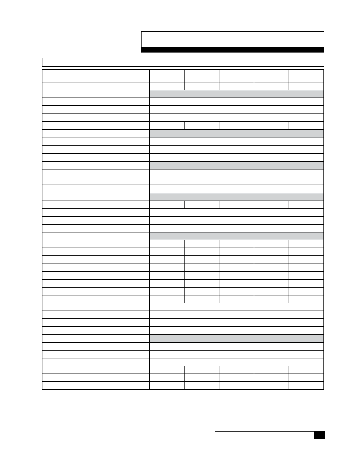
Series M2 Specifications
NOTE The International Specifications for M2 are in Appendix A on page 87.
M2-2 M2-3 M2-4 M2-5 M2-6
Nominal Capacity, GPD* 4000 5800 7500 9000 10000
Dimensions, Series M2 Units
Width - in [mm] 25.8 [655.3]
Depth - in [mm] 29.3 [744.2]
Height - in [mm] 52.6 [1336]
Operating Weight lb [kg] 198 [89.1] 228 [102.6] 258 [116.1] 288 [129.6] 318 [143.1]
Unit Connections
Inlet (NPT) 0.75"
Product (Tube) 0.5"
Concentrate (Tube) 0.5"
Electrical
Motor Horsepower (hp) 1.0
Power Requirement (VAC/Hz/phase) 208–230/60/1
Full Load Current (amp) 3.4-3.7
Hydraulic - Prefilter
Housing Quantity 2 3 4 5 6
Cartridge Quantity 1
Cartridge Size - in [mm] 10 [254]
Cartridge Rating (micron) 5
Hydraulic - RO
RO Housing Quantity 2 3 4 5 6
RO Element Quantity 2 3 4 5 6
RO Element Length - in [mm] 40 [1016] 40 [1016] 40 [1016] 40 [1016] 40 [1016]
Product Flow - gpm [L/min]* 2.78 [10.52] 4.03 [15.25] 5.21 [19.72] 6.25 [23.66] 6.94 [26.29]
Concentrate Flow - gpm [L/min]* 2.78 [10.52] 2.69 [10.16] 3.47 [13.14] 2.08 [7.89] 2.31 [8.76]
Recovery (%)*
Design 50 60 60 75 75
Minimum 40 50 50 60 60
Maximum Module Feed Pressure psig [kPa] 160 [1103]
Nominal Module Feed Pressure psig [kPa] 140 [965]
Maximum Product Pressure psig [kPa] 40 [276]
Operating Temperature °F [°C] 40–100 [4–38]
Inlet Pressure
Minimum, dynamic psig [kPa] 15 [103]
Maximum, dynamic psig [kPa] 40 [276]
Maximum, static psig [kPa] 100 [689]
Required Inlet Feed Flow gpm [L/min] 5.56 [21.0] 6.71 [25.4] 8.68 [32.9] 8.33 [31.5] 9.26 [35.1]
Pump Flow @ 125 psi gpm [Lmin] 11.0 [41.6] 11.0 [41.6] 11.0 [41.6] 11.0 [41.6] 11.0 [41.6]
Salt Rejection, Nominal (%) 97 97 97 96 95
†Calculated using a 0.85 fouling factor
*Nominal capacity based on new RO membranes operating on a properly pretreated feed water of 500 ppm TDS as NaCl,
77 °F (25 °C), Silt Density Index (SDI) below 3, and supplying water to atmosphere. Productivity will vary depending on
the actual feed water quality and temperature.
Cat. No. 01023095
Series M2 Specifications 5

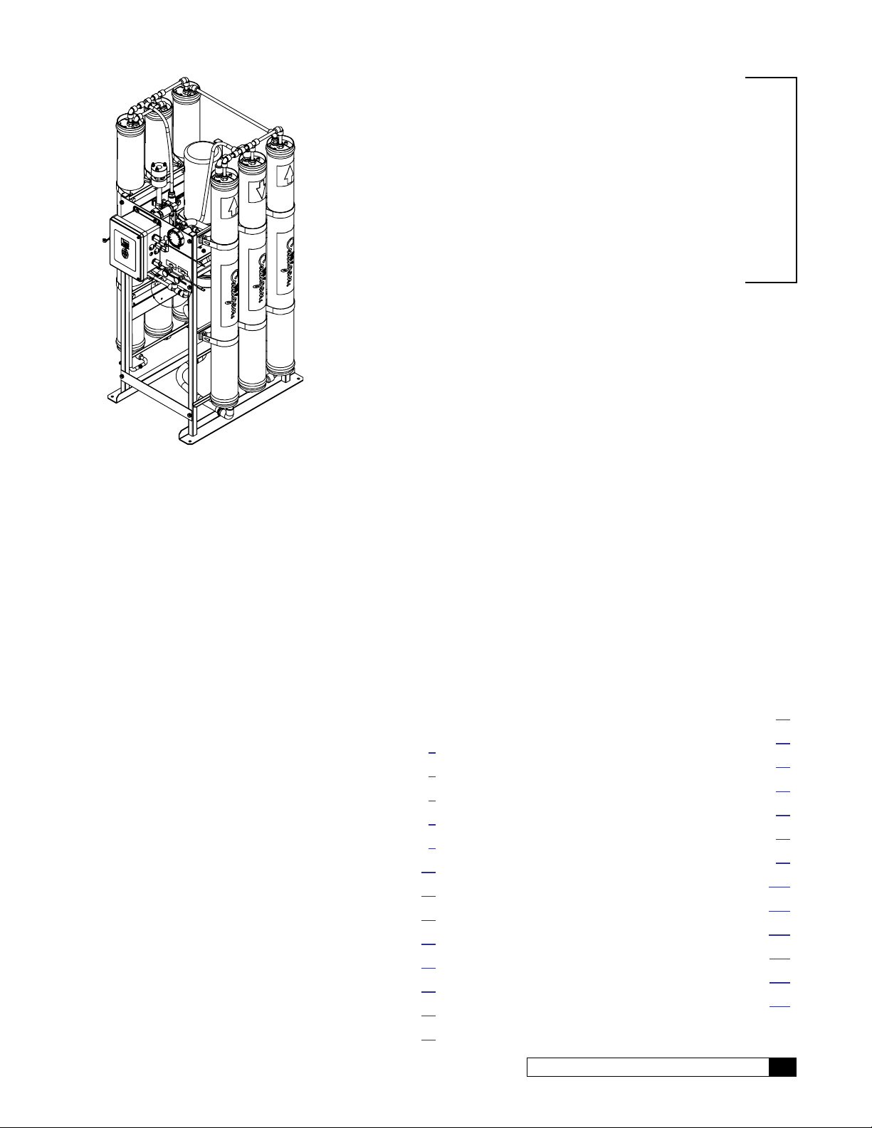
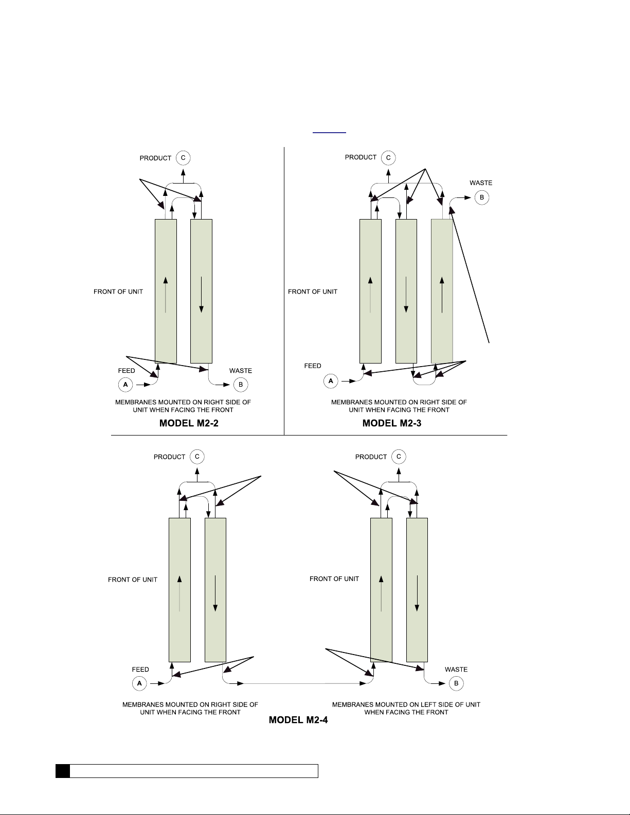
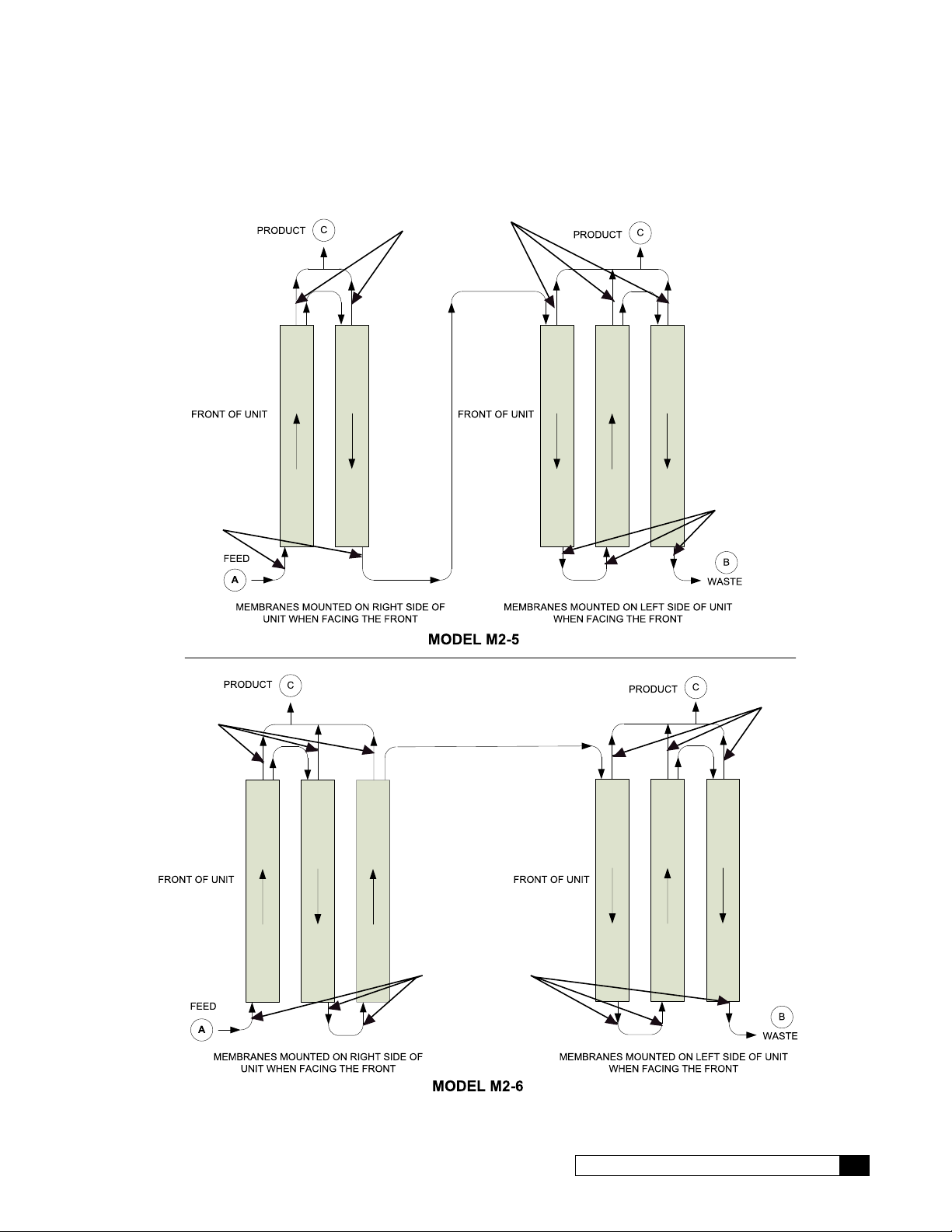
Unit Configurations
An M2-6 unit is pictured in Figure 1. See “M2 RO Parts Diagrams and Lists” on page 73 for a list of component part
numbers.
Membranes
Product Flow Meter
RO Controller (GROC)
Pump
Pump Feed Pressure
Recirculation Control
Waste Control
Prefilter
6 Culligan® Series M2 Reverse Osmosis
Figure 1. M2 RO front view.
6 Cat. No. 01023095
RO Installation
Unpacking the RO
This manual, the warranty, and registration card are packed in the control assembly box. Please complete the registration
card and mail it promptly.
NOTICE Examine each unit component carefully to check for loose or damaged parts. Report any apparent
or concealed shipping damage to the freight carrier immediately.
Materials Required
To install the system, the following items are required:
1. Level
2. Drill
3. Screwdrivers, including a small, flat-bladed (1/8” wide) screwdriver for wiring
4. Adjustable wrench
5. Tubing;
All—Nat 1/2” P.E. Tube, P/N 00901801 or 1/2" PVC piping Sched. 80 for Product
All—Nat 1/2” P.E. Tube, P/N 00901801 for Concentrate Waste.
All—3/4" PVC Sched. 80 for Feed
6. Bucket calibrated and stopwatch for taking flow rates
7. Clean rags
8. Thermometer
9. Portable Total Dissolved Solids meter
10. Safety glasses
Installation Location
The specification data lists the dimensions. Note that these figures do not account for working space around the unit and
the space for plumbing connections.
NOTICE The installer is responsible for the power supply to the unit.
The steel frame is designed to distribute the operating weight on an even floor space. If the floor is uneven, grout beneath
the steel frame feet so that the unit is evenly supported. Secure the base of the frame with four (4) 5/16” diameter bolts.
NOTICE Do NOT use any bolt size smaller than 5/16" diameter.
The unit must be located near a drain able to handle 3.5 gallons per minute (13 liters/min). This is in addition to the flow
from any other water treatment equipment.
CAUTION! The system must not be located near any corrosive chemicals which may cause failure
of the plastic or metal parts of the unit. In addition, do not locate the unit where the temperature may exceed the feed water temperature limits.
A 230 VAC/60 Hz/single-phase grounded power supply with 15 Amp fuse protection and a local disconnect switch is
required.
WARNING! The system must be grounded. An improperly grounded unit could cause injury from
electrical shock!
Cat. No. 01023095
RO Installation 7
RO Module Tubing
OFF-CENTER POR
OF END CAPS
T
For 3-D tube fitting diagrams, see the parts section starting on page 79.
CENTER PORT
OF END CAPS
CENTER PORT
OF END CAPS
T
CENTER PORT
OF END CAPS
OFF-CENTER PORT
OF END CAPS
OFF-CENTER POR
OF END CAPS
Figure 2. Module Tubing, two to four membranes.
8 Culligan® Series M2 Reverse Osmosis
8 Cat. No. 01023095
CENTER PORT
CENTER POR
OF END CAPS
T
OFF-CENTER POR
OF END CAPS
OF END CAPS
T
T
OFF-CENTER PORT
OF END CAPS
CENTER POR
OF END CAPS
Cat. No. 01023095
OFF-CENTER PORT
OF END CAPS
Figure 3. Module Tubing, five or six membranes.
RO Installation 9
WARNING! The system must be grounded. An improperly grounded unit could cause injury
from electrical shock!
Plumbing Installation
Refer to the appropriate hydraulic schematic/flow diagram on page 71 for further information.
Feed Water Connections
Connect pipe or tubing to the Feed water inlet. Observe the following:
1. To minimize pressure loss, the pipe or tubing size should be at least 3/4”.
2. Install optional pressure gauges (quantity 2 of P/N D1006272) before and after the pre-filter to measure the
pressure differential across the filter cartridge.
3. Install a tee, with an upstream shutoff valve on the branch, before the feed flow meter to provide a connection
for introducing cleaning solutions.
4. If necessary, install a pressure regulator (100 psi downstream max. setting) in the inlet plumbing, to assure
constant pressure and to prevent harmonic vibration.
5. Install a shutoff valve in the inlet plumbing to simplify maintenance and service.
6. If the feed water can be used for a short period, install bypass plumbing around the unit.
Concentrate Water Connections
1. Direct 1/2" tubing to drain from the outlet of the unit.
2. To prevent siphoning of the water in the unit to drain, raise the concentrate plumbing above the level of the
modules and provide an anti-siphon loop.
WARNING! An air gap must be provided between the end of the concentrate tubing and the
drain to prevent back-siphoning of drain contents.
Product Water Connections
The product water exits on the pump side of the unit in either 1/2” piping or tubing. Connect the product plumbing to the
fitting on the flow meter.
CAUTION! This unit produces high quality product water. This water can be contaminated by
plumbing following the unit or it can corrode the plumbing. Use only plumbing components of inert material that are compatible with the application.
The connection of the main product plumbing to service plumbing will depend on how the product water will be stored.
CAUTION! Reverse osmosis elements will fail immediately if product water is allowed to flow
backward into the unit.
Pressurized Storage Tank
The product water can be stored in a pressurized storage tank with the reverse osmosis unit controlled by a pressure
switch. Use the same components used for direct feed (see Figure 4) with the addition of a pressure switch which needs
to be wired to the control panel (see page 72 for RO standard wiring). A pressurized water storage kit is available under
part number D1018976.
10 Culligan® Series M2 Reverse Osmosis
10 Cat. No. 01023095
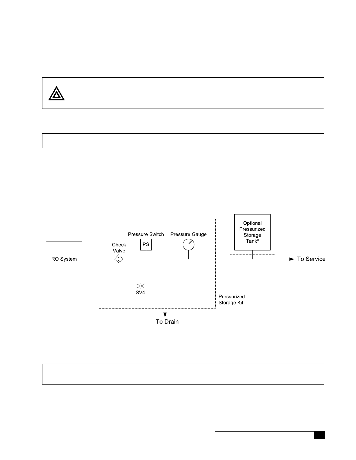
Non-Pressurized Product Water Storage Tank
*Use of Pressurized Storage Tank requires use of Pressurized Storage Kit D1018976.
Connect the product tubing to a bulkhead fitting at the top of the storage tank.
CAUTION! The highest point of the tubing should not be higher than four feet above the top of
the reverse osmosis modules, or the elements may be damaged.
Depending on the type of application, a level control may be required to turn the unit off when the storage tank is full.
Install the level control according to the instructions provided with the control. Refer to the wiring section in this manual for
electrical connections.
NOTICE If a repressurization pump is used, an additional level control is recommended to prevent the
pump from running dry if the storage tank is empty.
To maintain high water quality, a hydrophilic air vent filter, vacuum breaker, pop-off valve, ultraviolet lamp, and pressure
relief valve may be required.
Direct Feed
If the product water is to be used directly, without storage, a few precautions are necessary to prevent damage to the
elements. Install a pressure gauge, pressure relief valve, and a normally-open (“dump”) solenoid in the product water line
as shown in Figure 4. The pressure gauge will allow the operator to monitor the product water pressure. The relief valve,
which should be set to open at 40 psig, will prevent the product water pressure from exceeding 40 psi. The dump solenoid
will relieve all pressure when the unit is off.
(D1018976)
Figure 4. Direcfeed connection.
Wire the direct feed/pressurized storage solenoid valve in parallel with the motor.
NOTICE Install a check valve after these valves in case the service line remains under pressure. Product
back pressure will decrease the net pressure pushing water through the reverse osmosis elements. Therefore, the flow of product water will decrease.
Cat. No. 01023095
RO Installation 11
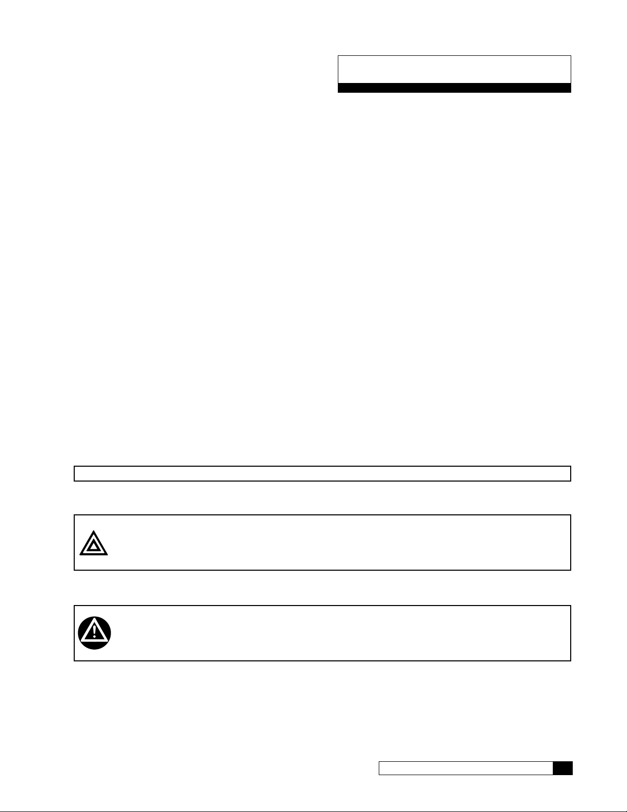
Electrical Installation
Incoming Power
Flush Kit 01025703
CAUTION! Observe the precautions listed below before the electrical installation of your GROC
controller. Failure to do so might cause permanent damage to the RO controller.
Electrical Installation of M2 RO Controller
Pre-Installation Recommendations
• Follow the local electrical code requirements.
• Be sure electrical power is off and disconnected at the source before completing any wiring/cabling connections.
• DO NOT include the GROC wiring cables in any conduit or raceway containing other 120-volt or higher circuits.
• Maintain a distance of at least 10 feet between the GBE controller and any electrical distribution panels, raceways
carrying 300 volts or more.
• Use the cabling provided. Failure to do so may affect performance of the GBE controller adversely.
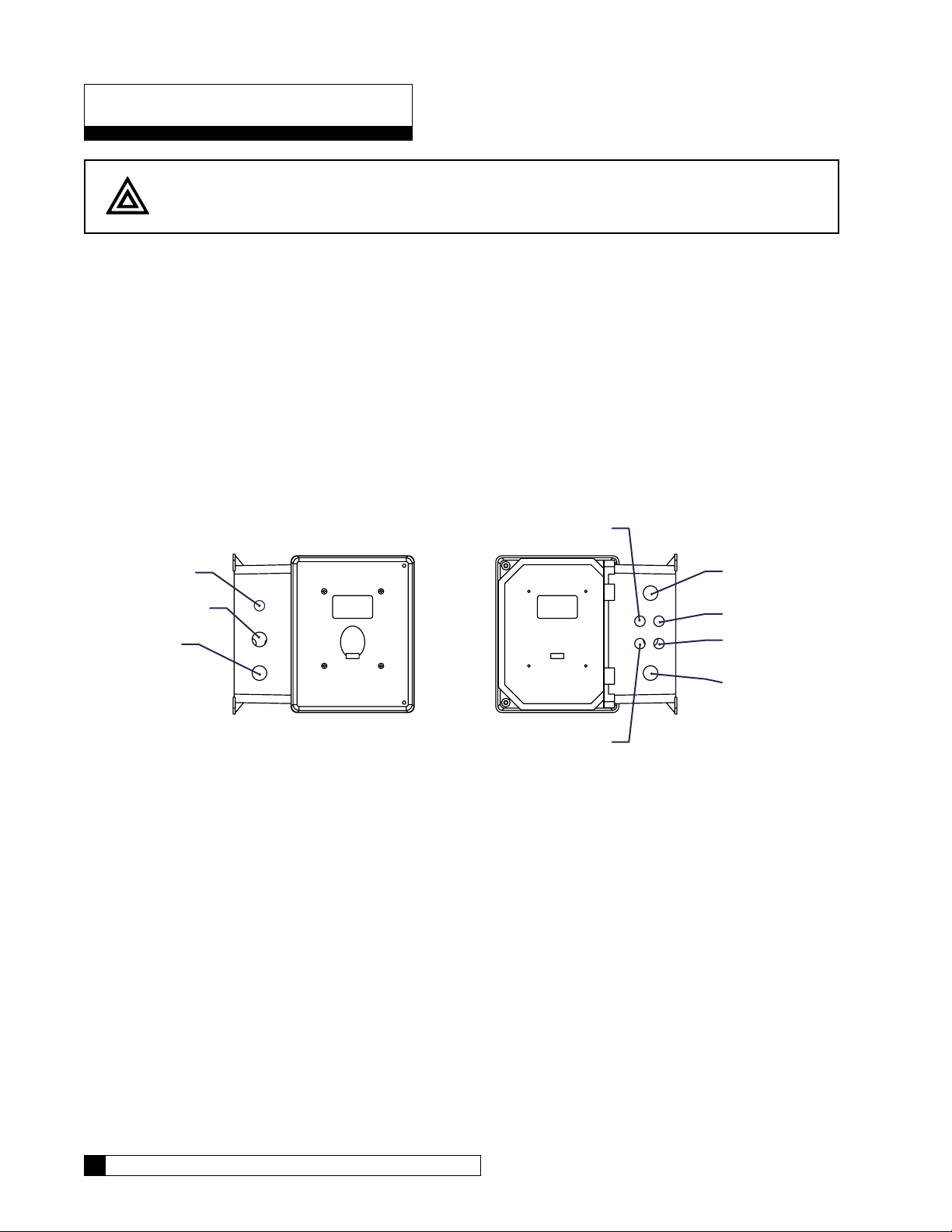
Series M2 Electrical Installation
To open the control panel, loosen the two screws and carefully open the cover by rotating it to the left.
Plugged
Product TDS
Motor Cord
Feed Flow Meter
Solenoid Valve 1
Optional for Fast
Product Flow Meter
Pressure Switch
Figure 5. M2 controller connections.
12 Culligan® Series M2 Reverse Osmosis
12 Cat. No. 01023095
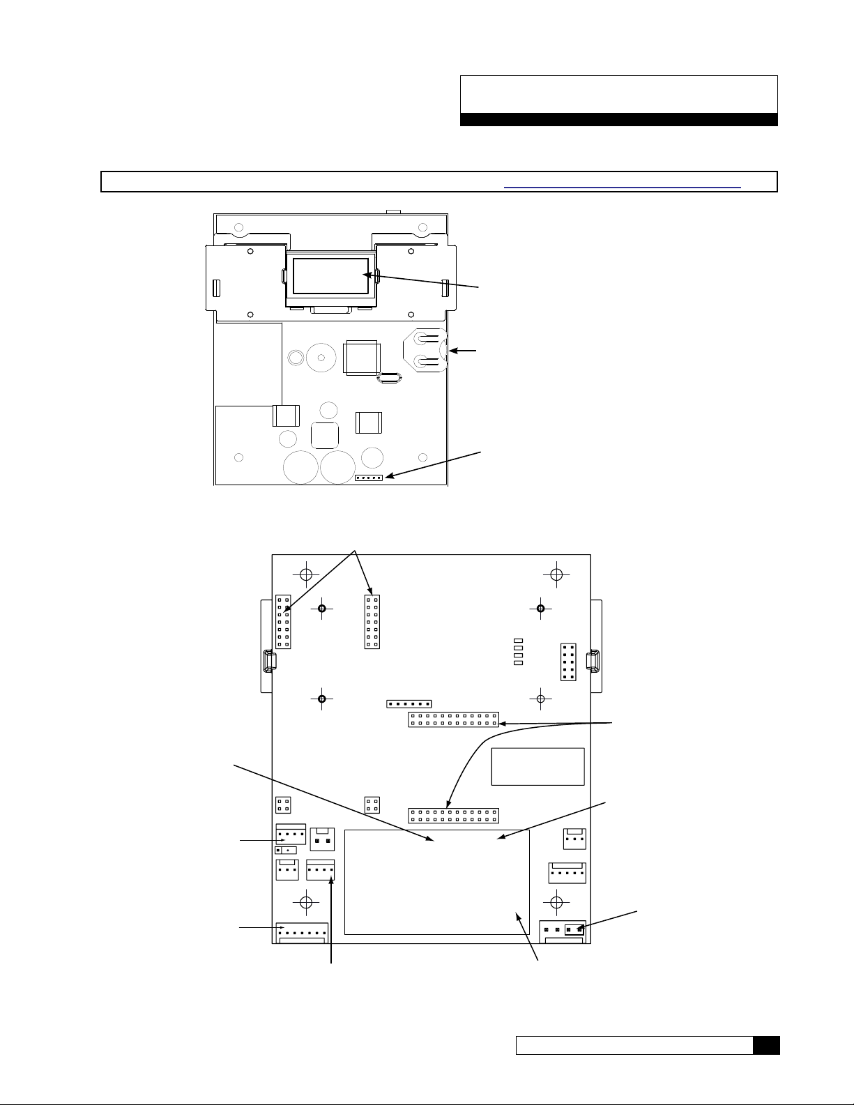
GROC Board Layout
Inlet Flow Meter (J13)
Modem
Series Global RO Controller Circuit Board Layout—Front
NOTE For a detailed explanation on wiring the circuit boards, refer to “GBE RO Controller Wiring” on page 72
OLED display
Battery
CR2032 (Postitive Side Up)
Keypad connector
Pressure Switch and
Pretreat Lockout (J2)
Hi and Lo Float
Switches (J12)
MT Board (J20)
Figure 6. GROC circuit board layout—front
Connectors
P/N: XXXXXXXX rev. X
VENDOR: XXXXXX
DATE CODE: WK/YY
HEX FILE: XXXXXXXX rev. X
24VAC
Remote Display
RF Board Connector
Product Flow Meter (J1)
Power
Cat. No. 01023095
Aux Board
Figure 7. GROC circuit board layout—back
GROC Board Layout 13
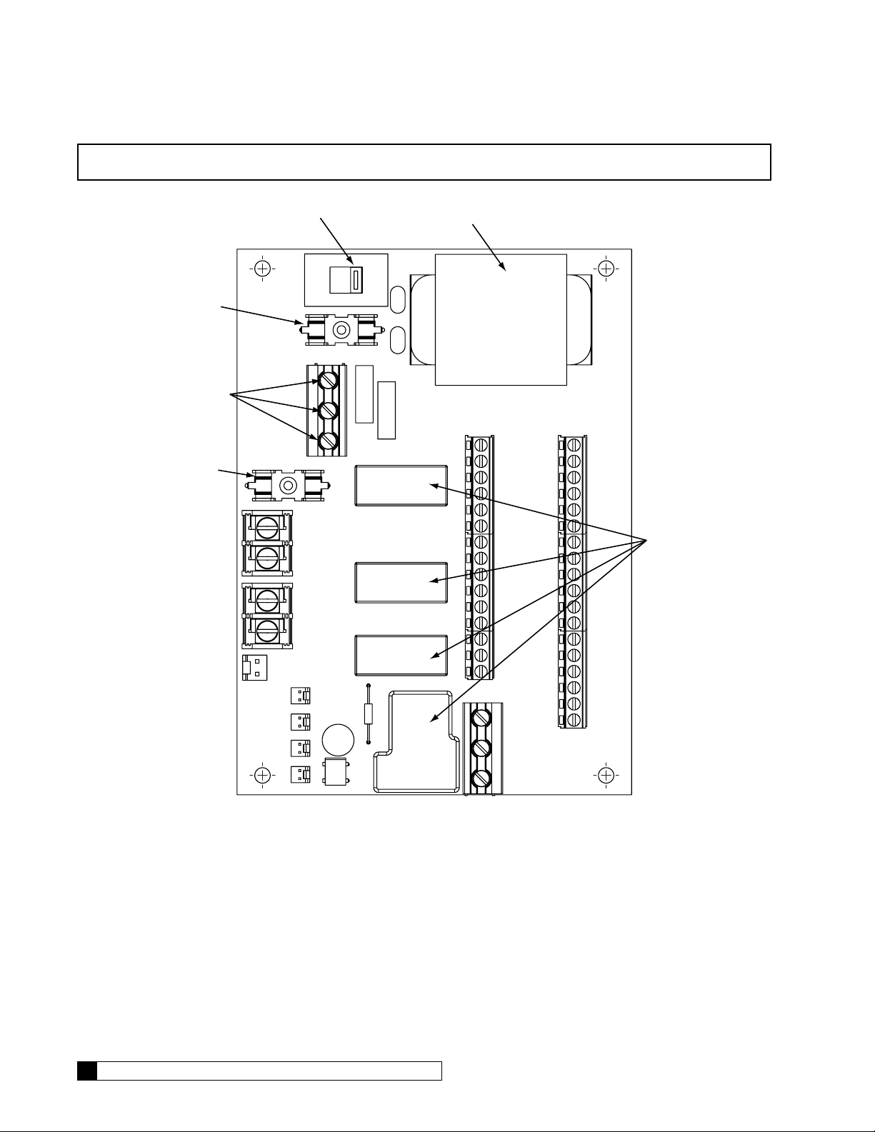
NOTE For Series M2 RO Systems, make sure the voltage selector switch is set at 230 VAC.
Voltage Selector Switch
Transformer
Fuse 315mA
Power
115V-230VAC
50-60Hz
Fuse 5A
115
230
Relays
14 Culligan® Series M2 Reverse Osmosis
Figure 8. GBE 115V/230V relay board.
14 Cat. No. 01023095

GROC Programming
Program Data Input
There are a few items to note that can make programming the Culligan® Global Reverse Osmosis Controller (GROC)
easier:
Slew Rates This term refers to the speed at which the display moves through the input of material. For ex-
ample, holding down the up arrow key for (5) seconds when inputting minutes for Time of Day
will cause the minutes to pass in (10) minute blocks of time. Press the up arrow or down arrow
keys for shorter periods (less than 5 seconds) will slow the rate. To move through the programming slowly, do not hold down the up arrow or the down arrow keys.
Beeper A beeper is available to assist the user by providing an audible tone (about 70 decibels) to signi-
fy valid (one beep) and invalid (three beeps) key presses. The beeper can be deactivated in the
programming mode. (If error occurs, beep will still sound even if set to “No” programming.)
Programming
Mode Timeout
Program Input
Acceptance
NOTE The following programming section is used for the G1, M2, G2 & G3 RO systems. The controller used
on the G1 & M2 RO units have the same programming but the controller has fewer features. Unless
otherwise specified, the programming is applicable to all units. Features not available on the G1 and
M2 are noted with a double-cross symbol (‡).
If there is no keypad activity for a one (1) minute period while in the programming mode, the
controller will exit the programming mode and return to the main display. Any setting that was
changed prior to the control timing out will revert to the original value. Pressing the CHECK
MARK button saves the setting.
For programming information to be accepted, the check mark key must be depressed prior to
programming mode timeout.
Cat. No. 01023095
GROC Programming 15
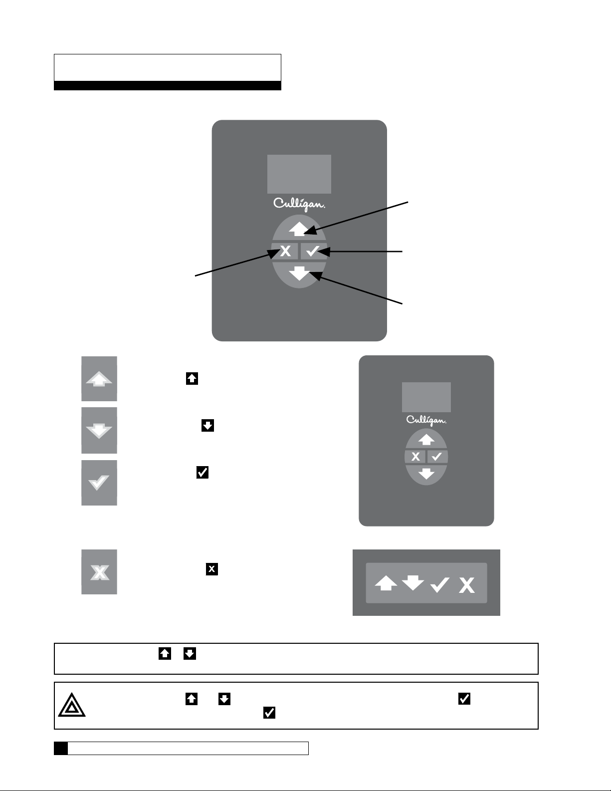
Menu and Key Navigation
ARROW Button
CANCEL
Key Pad Familiarization
or EXIT Button
UP ARROW Button
CHECK MARK Button
DOWN
UP ARROW button: scrolls up the menu
DOWN ARROW button: scrolls down the
menu
CHECK MARK button: selects the highlighted option, opens a new screen, or accepts a
changed setting
Controller
CANCEL or EXIT button: returns to the previous screen or cancels a changed setting
Remote
NOTE Hold down the or button to quickly scroll through the setting without repeatedly pressing the
button.
CAUTION! Use the and only to scroll through the menu settings. Do not use to perform
scrolling. Improper use of
16 Culligan® Series M2 Reverse Osmosis
might cause the controller to reset certain functions.
16 Cat. No. 01023095
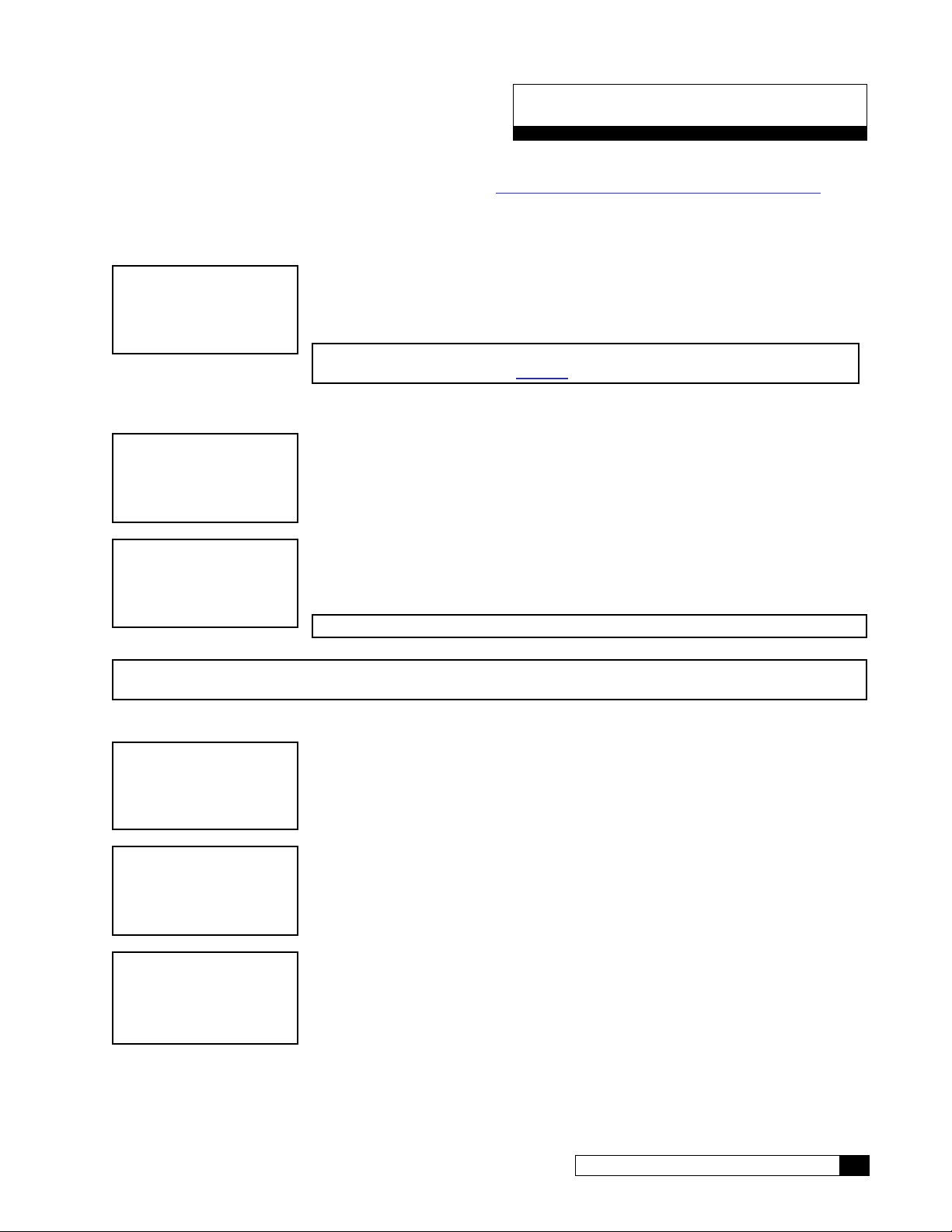
First Time Set Up
First Time Setup Procedure
If at any time you need to re-run the First Time Setup, refer to “Menu Default—Rerun First Time Setup” on page 19.
After completing the plumbing connections to the water softener, turn on and program the Global RO Controller.
Select Language (English, French, Italian, Spanish)
LANGUAGE
ENGLISH
1. Apply power to the unit. When a new controller is first turned on, the screen dis-
plays LANGUAGE. Press
gin first time setup in your preferred language.
NOTE You also can change the language setting after first-time setup from
the Setup menu. See page 22.
or and then to change the value and be-
Serial Number
FIRST TIME SETUP
PRESS DOWN ARROW
S/N:00012345
FWR***LT04
1. Plug in the wall transformer. When a new controller is first turned on, the screen
displays FIRST TIME SETUP. Press
2. The screen displays the serial number and firmware version and date installed for
this GROC. Press
ting, month.
to accept this information. The screen displays the first set-
.
MON DD YEAR
NOTE The S/N, firmware, and date displayed in this manual are examples only.
NOTE If this unit will be installed with a modem, it is required that this electronic serial number be reported to
Culligan on the IQR form.
Setting Up Date and Time
SET
MONTH JAN
SET
MONTH >JAN
SET
MONTH >FEB
Cat. No. 01023095
1. The screen displays the month setting. Press to accept this information and
view the day setting.
2. Press to select the item. The screen displays a cursor next to the value. This
indicates that the value may be changed by pressing the
3. Press to select a new value. The screen displays the new setting value next to
the cursor.
4. Press to select the next available value. You may press or to scroll
through all available options for this setting.
or button.
First Time Set Up 17

SET
DAY 1
5. Press to accept the selected screen value. The controller accepts the new
value and displays the next setting.
Other First Time Setup Settings
Screen Display Range Procedure
SET
DAY 1
SET YEAR
2012
CLOCK TYPE
12 HR
SET HOUR
12PM
SET
MINUTES 25
1–31
2010–2040
12 or 24
12AM–11PM
0–59
1. The screen displays the day setting. Press
then
2. The screen displays the year setting. Press
then
3. The screen displays the clock type setting. Press
4. The screen displays the hour setting. Press
then
5. The screen displays the minutes setting. Press
and then
to change the value and see the next setting.
to change the value and see the next setting.
and then to change the value and see the next setting.
to change the value and see the next setting.
to change the value and see the next setting.
or and
or and
or and
or
or
POWERON MODE
OFFLINE
Running
Offline
SYSTEM UNITS
US INCH
18 Culligan® Series M2 Reverse Osmosis
US INCH
METRIC
6. The screen displays the selected status of the RO when pow-
ered on. Press
value and see the next setting.
7. The screen displays the units of measure setting. Press
or and then to change the value and complete the
first-time setup.
NOTE This setting does not automatically change to metric
if you select a language other than English.
or and then to change the
18 Cat. No. 01023095

Completed First Time Setup
STARTING
JAN-01-12 12:01P
RUNNING
JAN-01-12 12:01P
1. When the setup is complete, the circuit board microprocessor automatically calcu-
lates the water conditioner capacity. The screen displays the initializing status and
the current date and time, and then transitions to the home screen.
2. The screen displays the current state of the RO system (RUNNING or OFFLINE)
and the date/time set for the unit. This is the default home screen.
Menu Lockout
It is possible to lock the keypad of the Global RO controller so that users will only have access to the INFORMATION, GO
TO RUNNING, and GO TO OFFLINE menu screens.
To lock the system, press and hold
NOTE Menu lockout may be completed only from the home screen.
and for 10 seconds. Repeat this process to unlock the keypad.
Menu Default—Rerun First Time Setup
Below is the procedure to default the board to factory settings and begin the first time setup.
1. Power down the control.
2. Press and hold
3. Power up the control while continuing to hold
and .
and for at least five (5) seconds.
4. Release
5. Power down the control.
6. Power up the control again. The screen lights up for two seconds and then displays the home screen.
7. Follow the first time setup process.
and . The display should be blank—if not go back to step 1.
Cat. No. 01023095
First Time Set Up 19
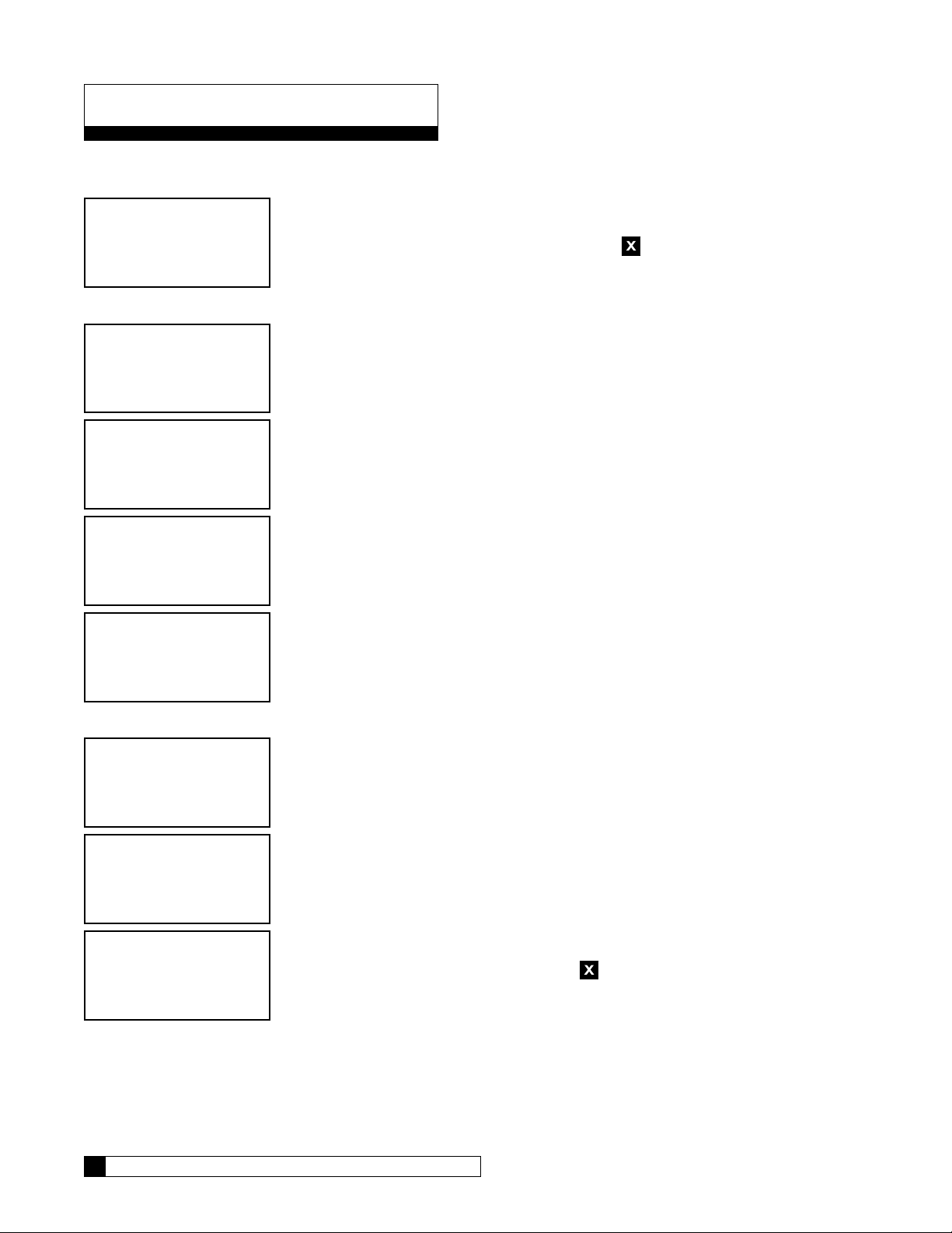
Basic Operation
After the first-time setup has been completed, the RO system will be online (RUNNING) or offline (OFFLINE). You can
change the operation status of the system from the main menu on the Global RO Controller.
RUNNING
JAN-01-12 12:01A
Go To Running
>1)GO TO RUNNING
2)GO TO OFFLINE
3)INFORMATION
4)SETUP
1. This is the home screen. Press any button except to display the main menu.
2. Press to select 1)GO TO RUNNING.
GO TO RUNNING
NO
STARTING
JAN-01-12 12:01P
STARTUP FLUSH
RUNNING
JAN-01-12 12:01A
Go To Offline
1)GO TO RUNNING
>2)GO TO OFFLINE
3)INFORMATION
4)SETUP
GO TO OFFLINE
NO
3. The GROC screen displays the GO TO RUNNING command. Press or
and then
(select NO to cancel the command and return to the main menu).
4. The screen displays the status of the unit as it initiates the startup process.
5. The home screen displays the operational status (RUNNING).
1. Press to select 1)GO TO OFFLINE.
2. The GROC screen displays the GO TO OFFLINE command. Press or
and then
(select NO to cancel the command and return to the main menu).
to change the value to YES if you want the system to start running
to change the value to YES if you want the system to stop running
OFFLINE
JAN-01-12 12:01A
20 Culligan® Series M2 Reverse Osmosis
3. The screen displays the main menu. Press repeatedly to return to the home
screen, which displays the operational status (OFFLINE).
20 Cat. No. 01023095

Setup
After completing the first time setup for the RO, you must also complete the system setup for flush modes, accessories,
and error limits before completing the initial startup.
Flow Meter K-Factor setting is required during setup. All other RO settings are optional depending on the accessories
installed. The RO controller does not require any specific setup to run unless accessories are installed or will be installed.
RO accessories include:
Accessory Global RO Controller (GROC) Setting
Flush Valves Setup—>Flush Modes
Flow Meters Setup—>Accessories—>Flow Meters
Modem Setup—>Accessories—>Modem
Wireless Remote, RF Board Setup—>Accessories—>Wireless Rem—>Channel #
Level Controls Setup—>Accessories—>Switch Inputs
Repressurization System Setup—>Accessories—>Switch Inputs
Pretreatment Lockout Setup—>Accessories—>Switch Inputs
Pressure Transducers (G2, G3 only) Setup—>Accessories—>Press Gauges
System Setup
Set Up Time/Date
If the unit loses time for some reason, you can use this setting to reset the correct date and time. Please note that if you
have a modem installed and connected to the phone line, the unit will check for the correct time each time it calls in.
RUNNING
JAN-01-12 12:01P
1. From the default home screen, press . The screen displays the main menu.
1) GO TO RUNNING
2) GO TO OFFLINE
3) INFORMATION
>4) SETUP
2. Press to scroll to 4) SETUP.
3. Press to select the SETUP menu.
>1) TIME/DATE
2) LANGUAGE
3) POWERON MODE
4. Set Time/Date is the first menu item, so press to select 1) SET TIME/DATE.
The screen displays the first setting that can be changed.
4) FLUSH MODES
Time/Date Settings
Screen Display Range Procedure
SET
MONTH JAN
Jan–Dec
1. The screen displays the month setting. Press
and then
to change the value and see the next setting.
or
SET
DAY 1
Cat. No. 01023095
1–31
2. The screen displays the day setting. Press
then
to change the value and see the next setting.
or and
Setup 21

Screen Display Range Procedure
SET YEAR
2012
CLOCK TYPE
12 HR
SET HOUR
12PM
2010–2040
12 or 24
12AM–11PM
3. The screen displays the year setting. Press
then
4. The screen displays the clock type setting. Press
5. The screen displays the hour setting. Press
then
to change the value and see the next setting.
and then to change the value and see the next setting.
to change the value and see the next setting.
or and
or
or and
SET
MINUTES 25
DAYLIGHT SAVING
YES
0–59
YES
NO
6. The screen displays the minutes setting. Press
and then
7. The screen displays whether you observe daylight savings
time where the RO unit is installed. Press
then
menu.
to change the value and see the next setting.
or and
to change the value and return to the Time/Date
RUNNING
JAN-01-12 12:01P
8. Press to return to the home screen.
Set Up Language
Use the language setting to change the displayed language on the RO controller.
NOTE Ensure the units of measure (US, Metric) are appropriate. See page 18 to change if necessary.
RUNNING
JAN-01-12 12:01P
1. From the default home screen, press . The screen displays the main menu.
or
1) GO TO RUNNING
2) GO TO OFFLINE
3) INFORMATION
>4) SETUP
2. Press to scroll to 4) SETUP.
3. Press to select the SETUP menu.
1) TIME/DATE
>2) LANGUAGE
3) POWERON MODE
4. Press to select 2)LANGUAGE. The screen displays the last selected language of the RO controller.
4) FLUSH MODES
22 Culligan® Series M2 Reverse Osmosis
22 Cat. No. 01023095

LANGUAGE
ENGLISH
1) TIME/DATE
>2) LANGUAGE
3) POWERON MODE
4) FLUSH MODES
Set Up Power On Mode
RUNNING
JAN-01-12 12:01P
1) GO TO RUNNING
2) GO TO OFFLINE
3) INFORMATION
>4) SETUP
1) TIME/DATE
2) LANGUAGE
>3) POWERON MODE
4) FLUSH MODES
5. Press or and then to change the display to your preferred
language.
6. The screen displays the setup menu in the selected language of the RO controller.
1. From the default home screen, press . The screen displays the main menu.
2. Press to scroll to 4) SETUP.
3. Press to select the SETUP menu.
4. Set Time/Date is the first menu item, so press to select 3)POWERON
MODE.
POWERON MODE
5. Press or and then to select Power On Mode options.
OFFLINE
RUNNING
OFFLINE
RUNNING
JAN-01-12 12:01P
6. Press to return to the home screen.
The RO system will start whenever power is supplied.
The RO system will go into standby when power is supplied to the unit.
Flush Modes
The GBE RO controller can be programmed to operate up to six different flush modes. Multiple flush modes can be specified and operating at any one time. If any one or more flush modes are calling for flushing to happen at a certain time, the
flush will take place. Some flush modes require additional plumbing and components such as solenoid valves.
Startup Flush
In this mode the fast flush solenoid (SV-2, Optional) opens for a specified number of minutes each time that the pump
turns on.
Standby Flush
In this mode any time that the system state is in STANDBY, the inlet AND fast flush solenoids open for a specified number of
minutes every specified number of hours. This is a line-pressure-level flush (ie the pump does NOT turn on during this flush).
Cat. No. 01023095
Setup 23
Time Trigger Flush
'UDLQ
3XPS
In this mode, any time that the system state is in RUNNING, the fast flush solenoid (SV-2, Optional) will open for a specified number of minutes every specified number of hours. Note that the pump is ON during this flush.
Flow Trigger Flush
In this mode, any time that the system state is in RUNNING, the fast flush solenoid (SV-2, Optional) will open for a specified number of minutes every specified number of PRODUCT RO water generated. Note that the pump is ON during this
flush.
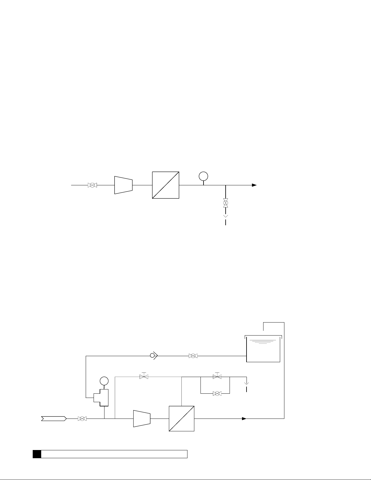
Quality Flush
If this mode is enabled, the product diversion solenoid (SV-3, NOT INCLUDED) is opened as soon as the pump turns on
when the RO system is RUNNING. This solenoid will remain open until the measured product TDS drops below the specified quality flush TDS setpoint or until the quality flush time period expires. If the TDS does not drop below the setpoint
during this period, the unit will switch to OFFLINE and the “product TDS High” error will be thrown. The Quality Flush solenoid valve is wired to the AUX board on the GBE RO controller at terminal AUX4. The solenoid valve must be 24 VAC.
7'6
7R 6HUYLFH
69
,QOHW
9DOYH
3XPS
0(0%5$1( +286,1*6
69
Figure 9. RO quality flush.
At startup, SV1 opens, and then the pump turns on. SV3 opens while the system monitors the product TDS level. The
user programs the maximum allowable product TDS and the number of minutes allowed following startup to reach the allowable TDS level. Usually at startup, the TDS level starts high and then drops. If the level drops below the allowable level
within the allowed time, then SV3 will close, and the unit is now in service. If the allowable TDS level cannot be reached,
the unit will shut down and generate an error message.
Permeate Flush
If this mode is enabled, the permeate flush solenoid (SV-3, NOT INCLUDED) is opened as soon as the
pump turns off. This solenoid will remain open until the permeate flush time period expires and permits water from an optional permeate storage tank to flush the membranes. The Permeate Flush solenoid valve is
wired to the AUX board on the GBE RO controller at terminal AUX4 (G1). The solenoid valve must be 24 Volt.
&KHFN
9DOYH
69
36
69
'UDLQ
)(('
69
24 Culligan® Series M2 Reverse Osmosis
Figure 10. RO permeate flush.
24 Cat. No. 01023095

At shutdown, the pump turns off and SV1 closes. Then fast flush solenoid valve SV2 and permeate valve SV3 open for a
programmed number of minutes. During this time, RO produt water stored either in an elevated atmospheric tank or in a
pressurized storage tank floods through the pump and the feed side of the membrane, and then SV2 and SV3 close. This
process provides RO-quality water during shutdown on both sides of the membrane to keep the membrane clean. This
process also ensures that the RO will provide high quality product water the next time the pump is turned on.
NOTE Quality Flush and Permeate Flush are mutually exclusive.
Flush Mode RO Pump Inlet Valve Waste (Fast) Flush Valve Product Flush Valve
Start Up On Open Open Closed
Standby Off Open Open Closed
Time On Open Open Closed
Flow On Open Open Closed
Quality On Open Closed Open
Permeate Off Closed Open Open
Table 1. RO pump and valve states during flush modes.
Any time that a Flush is actually taking place while the system state is RUNNING, the system will ignore the following error limits: delivered product TDS high, %recovery low, %recovery high, %reject low, membrane pressure drop, pump feed
pressure low. Once the flush ends, the error checking will resume. If the inlet pressure switch reports LOW pressure for
at least XX (XX is programmable at 1-30 seconds, at the main menu/setup/accessories/switch inputs menu) continuous
seconds, even if this is during or even partially during a flush time, the system will still recognize this instance as an error
condition, and it will begin the LOW PRESSURE process.
Flush Mode Setup
RUNNING
JAN-01-12 12:01P
1) GO TO RUNNING
2) GO TO OFFLINE
3) INFORMATION
>4) SETUP
1) TIME/DATE
2) LANGUAGE
3) POWERON MODE
>4) FLUSH MODES
1. From the default home screen, press . The screen displays the main menu.
2. Press to scroll to 4) SETUP.
3. Press to select the SETUP menu.
4. Set Time/Date is the first menu item, so press to select 4)FLUSH
MODES.
Cat. No. 01023095
Setup 25

Flush Mode Settings
Screen Display Range Procedure
>1) STARTUP
2) STANDBY
3) TIME TRIGGER
4) FLOW TRIGGER
START UP MODE
OFF
FLUSH DURATION
3
MINUTES
STANDBY MODE
OFF
FLUSH DURATION
3
MINUTES
Startup
Standby
Time Trigger
Flow Trigger
Qual Flush
Perm Flush
Off
On
1–180
Off
On
1–180
5. The screen displays the Flush Modes menu. Press
to scroll through the menu and then
setting.
6. The screen displays the Start Up Mode setting. This will flush
the drain prior to starting the pump. Press
then
sure flush.
7. If startup mode is set to ON, the screen displays the flush
duration of the drain. Press
change the value and then return to the Flush Mode menu.
8. The screen displays the Standby Mode setting. This will flush
the drain when the unit is in standby mode. Standby mode
may be triggered manually, by a STORAGE TANK FULL error, by a pretreatment lockout command, or other states. This
is a low pressure flush. Press
change the value if necessary.
9. If standby mode is set to ON, the screen displays the flush du-
ration setting. Press
value and then display the next setting.
to change the value if necessary. This is a line pres-
or and then to
or and then to change the
to select a flush mode
or and
or and then to
or
FLUSH EVERY
3
1–24
HOURS
TIME TRIG MODE
OFF
FLUSH DURATION
3
MINUTES
FLUSH EVERY
4
HOURS
26 Culligan® Series M2 Reverse Osmosis
1–180
1–24
Off
On
10. If standby mode is set to ON, the screen displays the flush in-
terval setting. Press
value and then return to the Flush Mode menu.
11. The screen displays the Time Trigger Mode setting. A flush
will be triggered after a specified amount of time has passed.
Press
necessary.
12. If time trigger mode is set to ON, the screen displays the flush
duration setting. Press
the value and then display the next setting.
13. If time trigger mode is set to ON, the screen displays the flush
interval setting. Press
the value and then return to the Flush Mode menu.
or and then to change the value if
or and then to change the
or and then to change
or and then to change
26 Cat. No. 01023095
 Loading...