

Culligan E2 Plus Series, E2 Plus-3, E2 Plus-2, E2 Plus-4, E2 Plus-5 Installation, Operation And Service Instructions
...Page 1

CULLIGAN
Cat. No. 01023094
Rev. D 05/03/13
DCO # 013581
Installation,
Operation and
Service
Instructions
®
Series E2 Plus
Reverse Osmosis Water Treatment
Systems
Models from 2011
©2013 Culligan International Com pa ny
Page 2
Attention Culligan Customer:
Your local independently operated Culligan dealer employs trained service and maintenance personnel who are experienced in the installation, function and repair of Culligan equipment. This publication is written specifically for these individuals and is intended for their use.
We encourage Culligan users to learn about Culligan products, but we believe that product knowledge is best obtained by
consulting with your Culligan dealer. Untrained individuals who use this manual assume the risk of any resulting property
damage or personal injury.
NOTICE Please send any suggestions for improving this manual to productmanuals@culligan.com.
WARNING! Electrical shock hazard! Prior to servicing equipment, disconnect power supply to
prevent electrical shock.
WARNING! If incorrectly installed, operated, or maintained, this product can cause severe injury.
Those who install, operate, or maintain this product should be trained in its proper
use, warned of its dangers, and should read the entire manual before attempting to
install, operate, or maintain this product. Failure to comply with any warning or
caution that results in any damage will void the warranty.
CAUTION! This product is not to be used by children or persons with reduced physical, sensory
or mental capabilities, or lack of experience or knowledge, unless they have been
given supervision or instruction.
CAUTION! Children should be instructed not to play with this appliance.
WARNING! This device complies with Part 15 of the FCC rules subject to the two following
conditions: 1) This device may not cause harmful interference, and 2) This device
must accept all interference received, including interference that may cause undesired
operation.
This equipment complies with Part 15 of the FCC rules. Any changes or modifications not expressly approved by the
manufacturer could void the user’s authority to operate the equipment. Changes or modifications not expressly approved
by the party responsible for compliance could void the user’s authority to operate the equipment.
CAUTION! To reduce the risk of fire, use only No. 26 AWG or larger telecommunications line
cord.
NOTE This system is not intended for use with water that is microbiologically unsafe or of unknown quality
without adequate disinfection either before or after the system.
NOTE Check with your public works department for applicable local plumbing and sanitation codes. Follow
local codes if they differ from the standards used in this manual. To ensure proper and efficient operation of the Culligan equipment to your full satisfaction, carefully follow the instructions in this manual.
Products manufactured and marketed by Culligan International Company (Culligan) and its affiliates are protected by patents issued or pending in the United States and other countries. Culligan reserves the right to change the specifications
referred to in this literature at any time without prior notice. Culligan, Aqua-Sensor, Tripl-Hull, and SoftMinder are trademarks of Culligan International Company or its affiliates.
Culligan International Company
9399 West Higgins Road, Suite 1100
Rosemont, Illinois 60018
1-847-430-2800
www.culliganmatrixsolutions.com
Page 3
Installation
Operation
Instructions
Culligan®
Series E2 Plus
Reverse Osmosis Water
Treatment Systems
Models From 2011
and
Contents
Introduction ........................................................................ 1
Features ............................................................................ 2
Series E2 Plus Specifications ............................................ 3
Unit Congurations ............................................................ 4
RO Installation ................................................................... 5
Operation ......................................................................... 10
Initial Startup.................................................................... 11
Accessories ..................................................................... 14
Service and Maintenance ................................................ 18
Flow Diagram .................................................................. 26
Wiring Diagram ................................................................ 27
E2 Plus RO Parts Diagrams and Lists............................. 28
Appendix A Series E2 Plus International ..................... 39
Appendix B Basic Principles ........................................ 51
Index ................................................................................ 53
Cat. No. 01023094
i
Page 4

This page intentionally left blank.
ii Culligan® Series E2 Plus Reverse Osmosis
ii Cat. No. 01023094
Page 5
Introduction
Read this Manual First
Before you operate the Culligan® Series E2 Plus reverse osmosis systems, read this manual to become familiar with the
device and its capabilities.
®
Culligan
This manual contains important information about the unit, including information needed for installation, operating, and
maintenance procedures. A troubleshooting section provides a guide for quick and accurate problem solving.
In order for the water treatment system to continue to provide high quality water, you must develop a thorough understanding of the system and its operation. Review this manual before making any attempt to install, operate, or service
the system. Installation or maintenance done on this system by an untrained service person can cause major damage to
equipment or property damage.
About this Manual
This manual:
This publication is based on information available when approved for printing. Continuing design refinements could cause
changes that may not be included in this publication.
Series E2 Plus reverse osmosis systems are designed to meet the needs of applications for high quality water.
• Familiarizes the operator with the equipment
• Explains installation and setup procedures
• Provides basic programming information
• Explains the various modes of operation
• Gives specifications and troubleshooting information
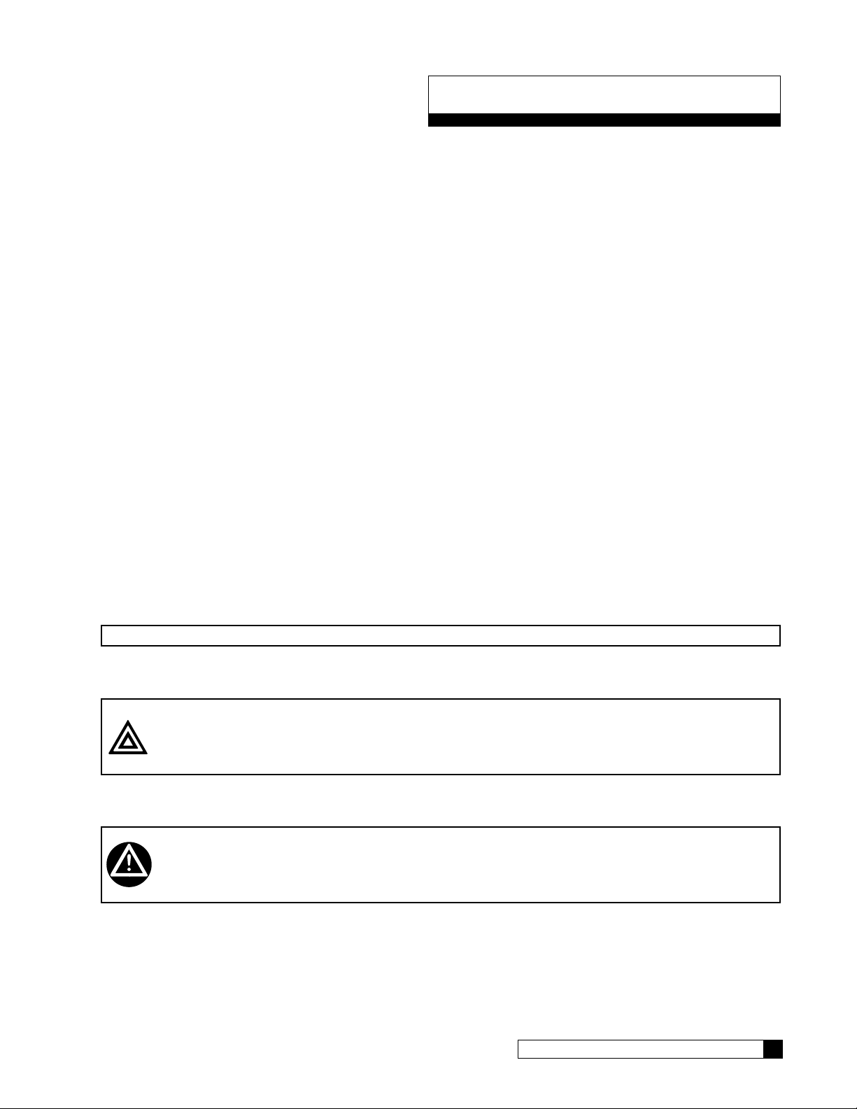
Safe Practices
Throughout this manual there are paragraphs set off by special headings.
Notice
Notice is used to emphasize installation, operation or maintenance information which is important, but does not present
any hazard. For example,
NOTICE The nipple must extend no more than 1 inch above the cover plate.
Caution
Caution is used when failure to follow directions could result in damage to equipment or property. For example,
CAUTION! Disassembly while under water pressure can result in flooding.
Warning
Warning is used to indicate a hazard which could cause injury or death if ignored. For example,
WARNING! Electrical shock hazard! Unplug the unit before removing the timer mechanism or
cover plates!
The CAUTION and WARNING paragraphs are not meant to cover all possible conditions and situations that may occur. It
must be understood that common sense, caution, and careful attention are conditions which cannot be built into the equipment. These MUST be supplied by the personnel installing, operating, or maintaining the system.
Be sure to check and follow the applicable plumbing codes and ordinances when installing this equipment. Local codes
may prohibit the discharge of acid or caustic solutions to drain. An extra solution tank should be used to neutralize the
solution before discharging to drain.
Use protective clothing and proper face or eye protection equipment when handling chemicals or power tools.
Cat. No. 01023094
Introduction 1
Page 6

Features
The Aqua-Cleer Series Reverse Osmosis systems are the direct result of Culligan’s long time experience in membrane
applications around the world. From process water for any size business to treating water for an entire city, Culligan has
the knowledge and the range of products you need to get the job done.
The E2 Plus reverse osmosis system is sized to serve small-to-medium-sized applications that require high-quality
reverse osmosis water. It is designed with the flexibility to closely match your treatment requirements from 2.78 to 6.94
gallons per minute (4,000 to 10,000 gallons per day). A rich standard feature set with multiple options can satisfy virtually
any application. Select the right size and choose any options needed to complete your system.
Key Product Features
• Simple System Integration
• Flexible Configurations
• Quick Delivery/Easy Installation
• Feed and Product Flow Meters (Rotameters)
• TDS Probe: Shuts the unit down if the product TDS exceeds a user specified threshold (optional)
• Culligan Electronic Features
• Pretreatment Lockout
• Storage Tank Level and Pressure Control
• Low Pressure Auto-Restart
Flush Options
• Start up flush: Inlet valve opens for one minute whenever system starts to make RO water. Flushes reject side of
membrane and reduces the time it takes the RO to rinse up to quality.
• Time flush: In the running mode, the inlet solenoid valve remains open, allowing the reject side of the RO to be
flushed based on preset number of running hours for a set number of minutes. (May extend membrane cleaning
frequency in some applications).
2 Culligan® Series E2 Plus Reverse Osmosis
2 Cat. No. 01023094
Page 7
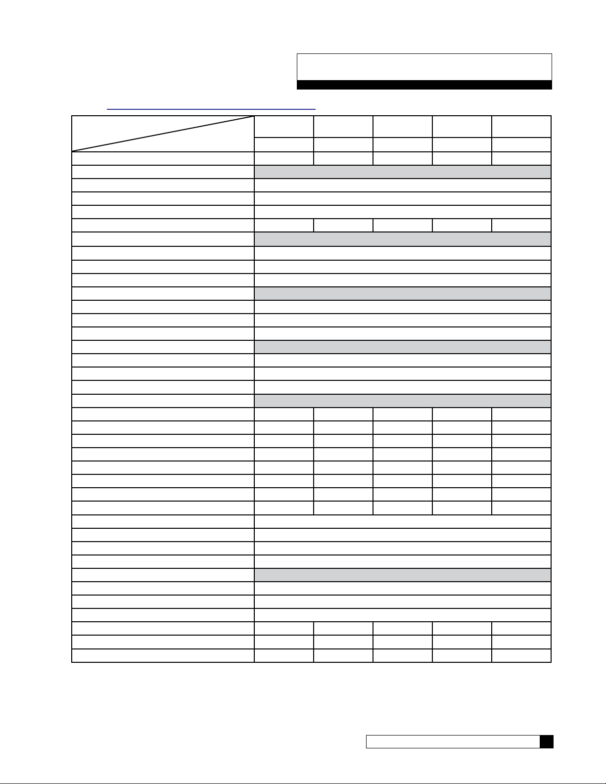
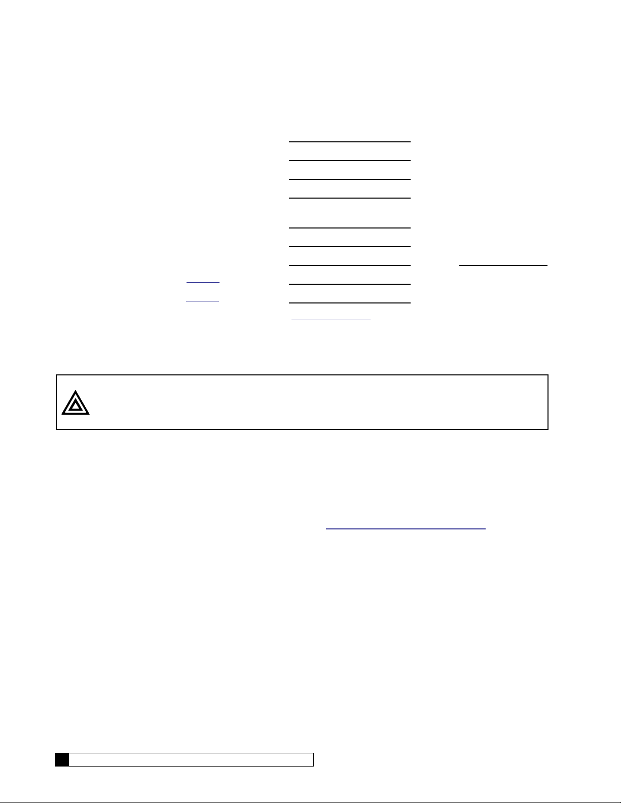
Series E2 Plus Specifications
NOTE “E2 Plus International Specifications” on page 39 details informations regarding 50Hz units.
Model
Part Number
Nominal Capacity, GPD* 4000 5800 7500 9000 10000
Dimensions, Series E2 Plus Units
Width - in [mm] 25.8 [655.3]
Depth - in [mm] 29.3 [744.2]
Height - in [mm] 52.6 [1336]
Operating Weight lb [kg] 198 [89.1] 228 [102.6] 258 [116.1] 288 [129.6] 318 [143.1]
Unit Connections
Inlet (NPT) 3/4 NPT
Product (Tube) 1/2 NPT
Concentrate (Tube) 0.5"
Electrical
Motor Horsepower (hp) 1.0
Power Requirement (VAC/Hz/phase) 208-230/60/1
Full Load Current (amp) 10.4/8.5
Hydraulic - Prefilter
Cartridge Quantity 1
Cartridge Size - in [mm] 10 [254]
Cartridge Rating (micron) 5
Hydraulic - RO
RO Housing Quantity 2 3 4 5 6
RO Element Quantity 2 3 4 5 6
RO Element Length - in [mm] 40 [1016] 40 [1016] 40 [1016] 40 [1016] 40 [1016]
Product Flow - gpm [L/min]* 2.78 [10.52] 4.03 [15.25] 5.21 [19.72] 6.25 [23.66] 6.94 [26.29]
Concentrate Flow - gpm [L/min]* 2.78 [10.52] 2.69 [10.16] 3.47 [13.14] 2.08 [7.89] 2.31 [8.76]
Recovery (%)*
Design 50 60 60 75 75
Minimum 40 50 50 60 60
Maximum Module Feed Pressure psig [kPa] 160 [1103]
Nominal Module Feed Pressure psig [kPa] 140 [965]
Maximum Product Pressure psig [kPa] 40 [276]
Operating Temperature °F [°C] 40–100 [4–38]
Inlet Pressure
Minimum, dynamic psig [kPa] 20 [103]
Maximum, dynamic psig [kPa] 40 [276]
Maximum, static psig [kPa] 100 [689]
Required Inlet Feed Flow gpm [L/min] 5.56 [21.0] 6.71 [25.4] 8.68 [32.9] 8.33 [31.5] 9.26 [35.1]
Pump Flow @ 125 psi gpm [Lmin] 11.0 [41.6] 11.0 [41.6] 11.0 [41.6] 11.0 [41.6] 11.0 [41.6]
Salt Rejection, Nominal (%) 97 97 97 96 95
†Calculated using a 0.85 fouling factor
*Nominal capacity based on new RO membranes operating on a properly pretreated feed water of 500 ppm TDS as NaCl,
77 °F (25 °C), Silt Density Index (SDI) below 3, and supplying water to atmosphere. Productivity will vary depending on
the actual feed water quality and temperature.
E2 Plus-2 E2 Plus-3 E2 Plus-4 E2 Plus-5 E2 Plus-6
01022839 01022840 01022841 01022842 01022843
Cat. No. 01023094
Series E2 Plus Specifications 3
Page 8
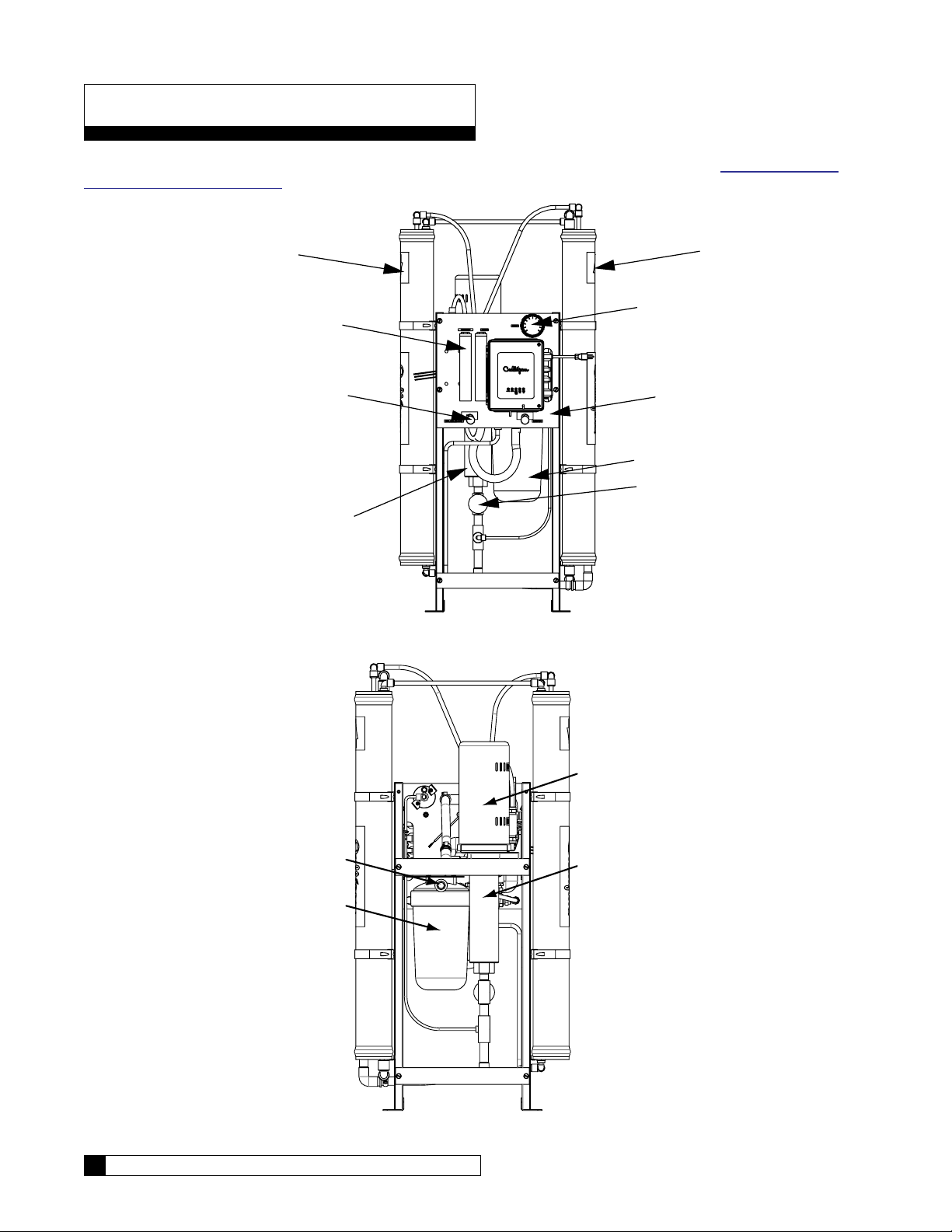
Unit Configurations
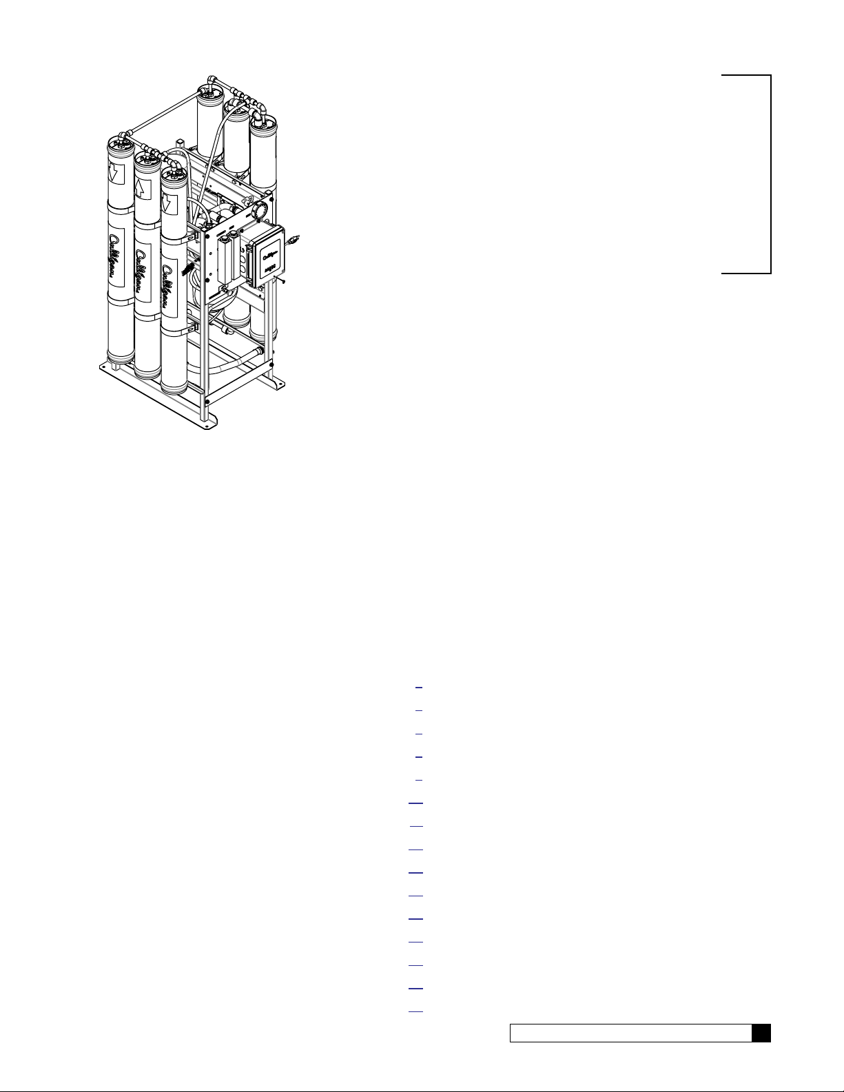
An E2-6 Plus unit is pictured in Figure 1 and Figure 2. Width of membrane rack varies with model. See “E2 Plus RO Parts
Diagrams and Lists” on page 28 for a list of component part numbers.
Filter
Arrays
Filter
Arrays
Feed and Product
Flow Meters
Water and Recirculation
Control Valves
Pump
Pump Pressure
Gauge
Front Panel
Assembly
Prefilter
Throttling
Valve
Figure 1. E2 Plus RO front view.
Inlet
Prefilter
4 Culligan® Series E2 Plus Reverse Osmosis
Motor
Pump
Figure 2. E2 Plus RO rear view.
4 Cat. No. 01023094
Page 9
RO Installation
Unpacking the RO
This manual, the warranty, and registration card are packed in the control assembly box. Please complete the registration
card and mail it promptly.
NOTICE Examine each unit component carefully to check for loose or damaged parts. Report any apparent
or concealed shipping damage to the freight carrier immediately.
Materials Required
To install the system, the following items are required:
1. Level
2. Drill
3. Screwdrivers, including a small, flat-bladed (1/8” wide) screwdriver for wiring
4. Adjustable wrench
5. Tubing;
All—1/2” PVC Tubing (P/N 00901801)
All—3/4" Feed piping,PVC Sched. 80
6. Clean rags
7. Thermometer
8. Portable Total Dissolved Solids meter
9. Safety glasses
Installation Location
The specification data lists the dimensions. Note that these figures do not account for working space around the unit and
the space for plumbing connections.
NOTICE The installer is responsible for the power supply to the unit.
The steel frame is designed to distribute the operating weight on an even floor space. If the floor is uneven, grout beneath
the steel frame feet so that the unit is evenly supported. Secure the base of the frame with four (4) 5/16” diameter bolts.
NOTICE Do NOT use any bolt size smaller than 5/16" diameter.
The unit must be located near a drain able to handle 5 gallons per minute (18.9 liters/min). This is in addition to the flow
from any other water treatment equipment.
CAUTION! The system must not be located near any corrosive chemicals which may cause failure
of the plastic or metal parts of the unit. In addition, do not locate the unit where the temperature may exceed the feed water temperature limits.
A 208-230 VAC/60 Hz/single-phase grounded power supply with 15 Amp fuse protection and a local disconnect switch is
required.
WARNING! The system must be grounded. An improperly grounded unit could cause injury from
electrical shock!
Cat. No. 01023094
RO Installation 5
Page 10
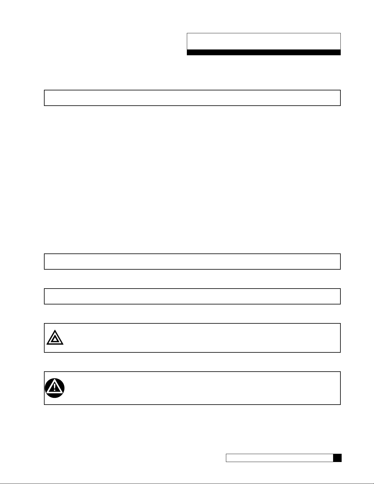
RO Module Tubing
For 3-D tube fitting diagrams, see the parts section starting on page 28.
CENTER PORT
OF END CAPS.
CENTER PORT
OF END CAPS.
OFF-CENTER PORT
OF END CAPS
CENTER PORT
OF END CAPS.
CENTER PORT
OF END CAPS.
MODEL E2-2 Plus MODEL E2-3 Plus
CENTER PORT
OF END CAPS.
OFF-CENTER PORT
OF END CAPS
CENTER PORT
OF END CAPS.
Figure 3. E2 Plus Module Tubing, two to four membranes.
6 Culligan® Series E2 Plus Reverse Osmosis
OFF-CENTER PORT
OF END CAPS
MODEL E2-4 Plus
6 Cat. No. 01023094
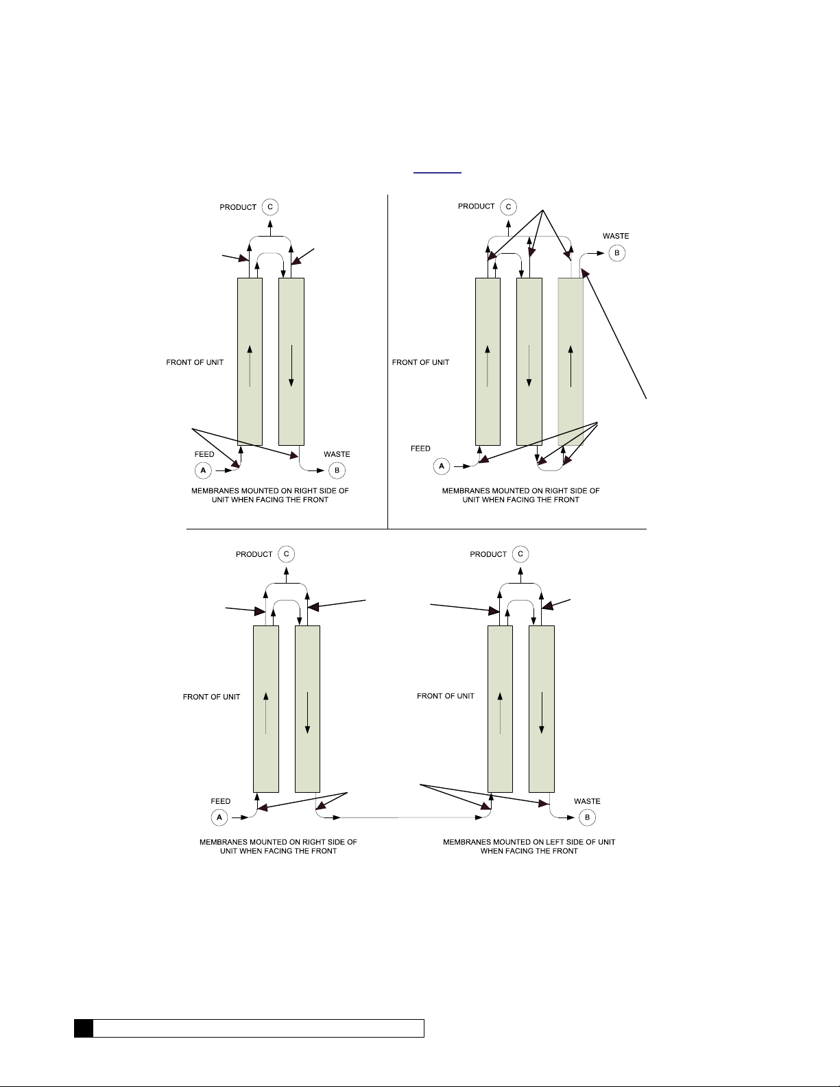
Page 11
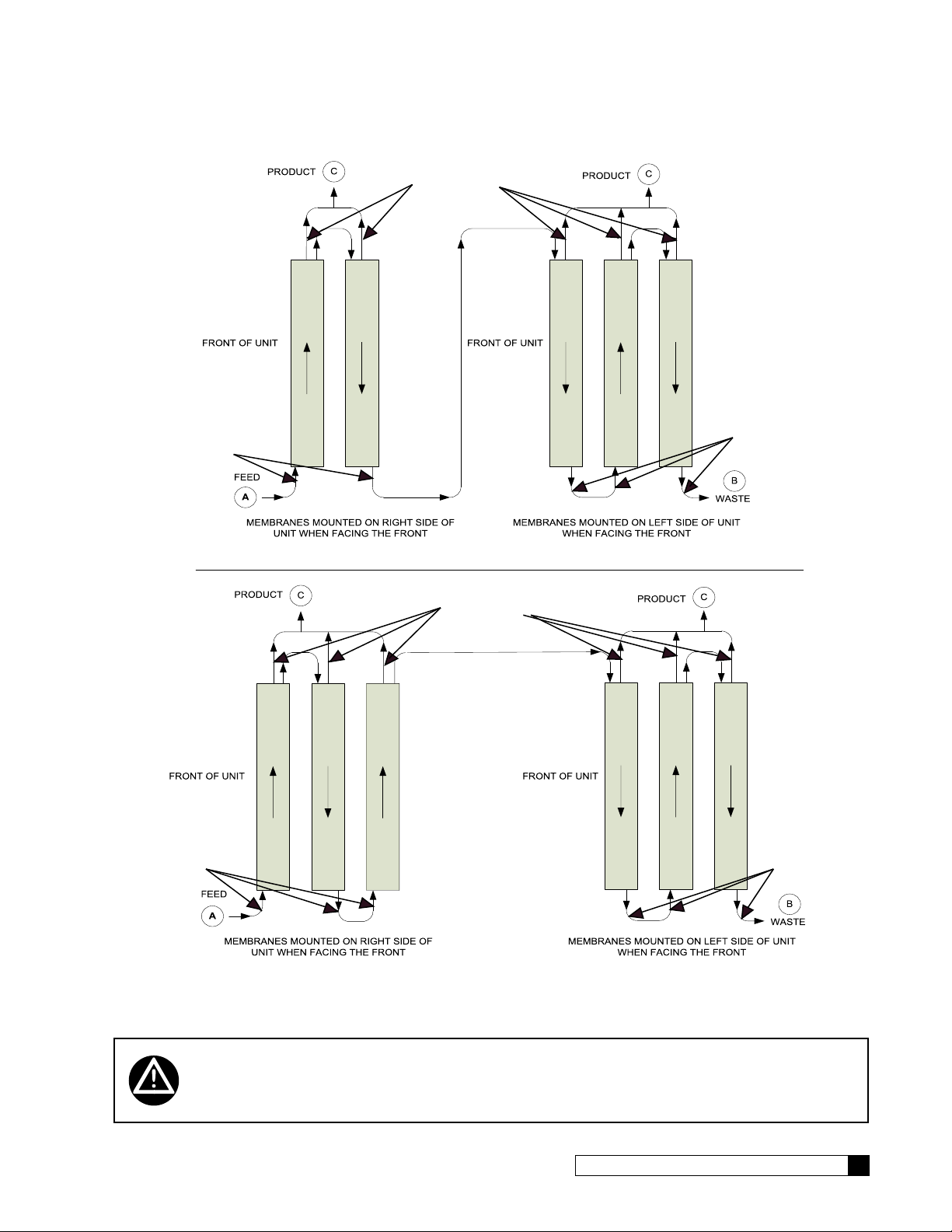
MODEL E2-5 Plus
MODEL E2-6 Plus
CENTER PORT
OF END CAPS.
OFF-CENTER PORT
OF END CAPS
CENTER PORT
OF END CAPS.
OFF-CENTER PORT
OF END CAPS
OFF-CENTER PORT
OF END CAPS
OFF-CENTER
PORT OF END
CAPS
Figure 4. E2 Plus Module Tubing, five or six membranes.
WARNING! The system must be grounded. An improperly grounded unit could cause injury
from electrical shock!
Cat. No. 01023094
RO Installation 7
Page 12
Plumbing Installation
Refer to the appropriate hydraulic schematic/flow diagram on page 26 for further information.
Feed Water Connections
Connect pipe or tubing to the Feed water inlet. Observe the following:
1. To minimize pressure loss, the pipe or tubing size should be at least 3/4”.
2. Install optional pressure gauges (quantity = 2 of P/N D1006272) before and after the pre-filter to measure the
pressure differential across the filter cartridge.
3. Install a tee, with a shutoff valve on the branch, before the feed flow meter to provide a connection for introducing cleaning solutions.
4. If necessary, install a pressure regulator (100 psi upstream max. setting) in the inlet plumbing, to assure constant pressure and to prevent harmonic vibration.
5. Install a shutoff valve in the inlet plumbing to simplify maintenance and service.
6. If the feed water can be used for a short period, install bypass plumbing around the unit.
Concentrate Water Connections
1. Direct 1/2" tubing to drain from the outlet of the unit.
2. To prevent siphoning of the water in the unit to drain, raise the concentrate plumbing above the level of the
modules and provide an anti-siphon loop.
WARNING! An air gap must be provided between the end of the concentrate tubing and the
drain to prevent back-siphoning of drain contents.
Product Water Connections
The product water exits on the pump side of the unit in either piping or tubing. Connect the product plumbing to the fitting
on the flow meter.
CAUTION! This unit produces high quality product water. This water can be contaminated by
plumbing following the unit or it can corrode the plumbing. Use only plumbing components of inert material that are compatible with the application.
The connection of the main product plumbing to service plumbing will depend on how the product water will be stored.
CAUTION! Reverse osmosis elements will fail immediately if product water is allowed to flow
backward into the unit.
Pressurized Storage Tank
The product water can be stored in a pressurized storage tank with the reverse osmosis unit controlled by a pressure
switch. Use the same components used for direct feed (see Figure 5) with the addition of a pressure switch which needs
to be wired to the control panel (see page 27 for RO standard wiring). A pressurized water storage kit is available under
part number D1018976.
8 Culligan® Series E2 Plus Reverse Osmosis
8 Cat. No. 01023094
Page 13
Non-Pressurized Product Water Storage Tank
Pressure Gauge
Connect the product tubing to a bulkhead fitting at the top of the storage tank.
CAUTION! The highest point of the tubing should not be higher than four feet above the top of
the reverse osmosis modules, or the elements may be damaged.
Depending on the type of application, a level control may be required to turn the unit off when the storage tank is full.
Install the level control according to the instructions provided with the control. Refer to the wiring section in this manual for
electrical connections.
NOTICE If a repressurization pump is used, an additional level control is recommended to prevent the
pump from running dry if the storage tank is empty.
To maintain high water quality, a hydrophilic air vent filter, vacuum breaker, pop-off valve, ultraviolet lamp, and pressure
relief valve may be required.
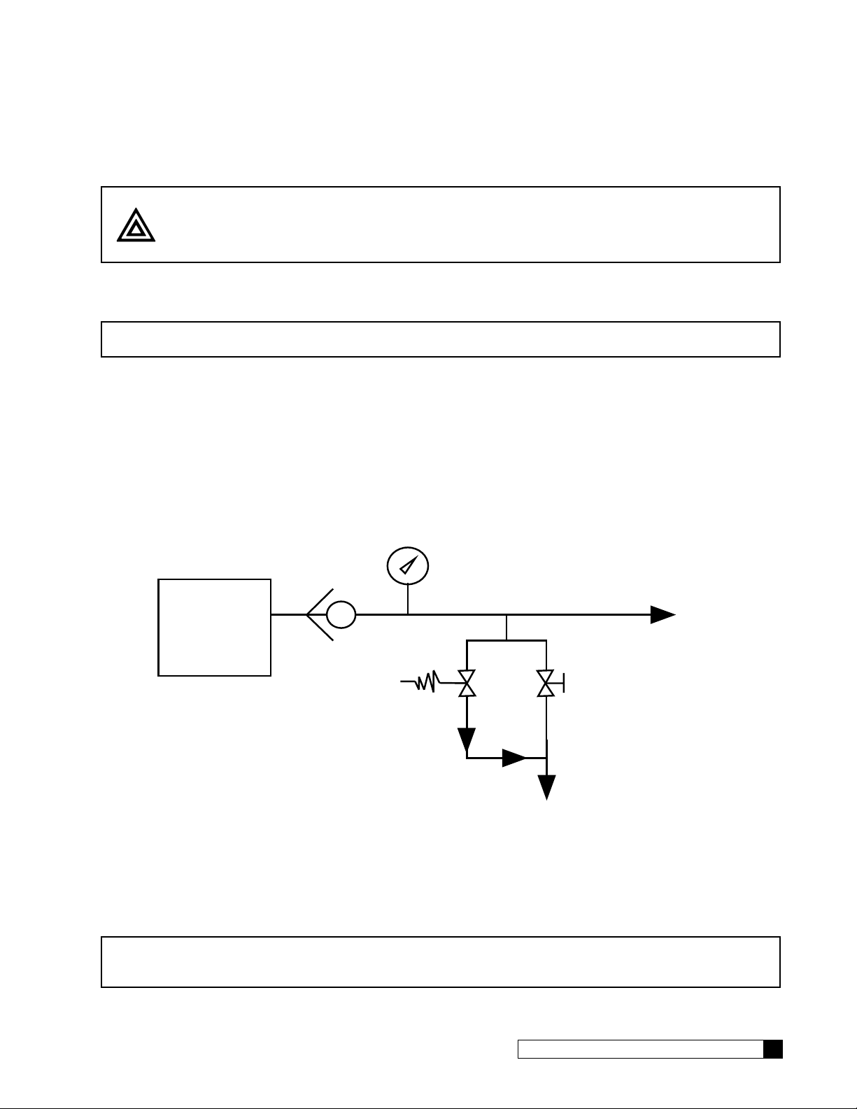
Direct Feed
If the product water is to be used directly, without storage, a few precautions are necessary to prevent damage to the
elements. Install a pressure gauge, pressure relief valve, and a normally-open (“dump”) solenoid in the product water line
as shown in Figure 5. The pressure gauge will allow the operator to monitor the product water pressure. The relief valve,
which should be set to open at 40 psig, will prevent the product water pressure from exceeding 40 psi. The dump solenoid
will relieve all pressure when the unit is off.
P/N 00440343
Check Valve
Reverse
Osmosis
System
Solenoid
Valve
Product Line
To Service
3
Pressure
Relief Valve
1
To Drain
Figure 5. Direct feed connection.
Wire the direct feed/pressurized storage solenoid valve in parallel with the motor.
NOTICE Install a check valve after these valves in case the service line remains under pressure. Product
back pressure will decrease the net pressure pushing water through the reverse osmosis elements. Therefore, the flow of product water will decrease.
Cat. No. 01023094
RO Installation 9
Page 14

Operation
CP Controller Board
The CP controller board controls the Culligan E1, M1, and E2 commercial RO product lines. This board requires no programming and has the following capabilities:
• 208-230 VAC single-phase motor up to 1 HP
• Line pressure front side flush prior to startup
• Line pressure front side flush every two hours of continuous make water
• Shut-down upon loss of inlet water pressure and auto-restart
• Power-loss and return auto-restart
• Pretreatment lockout
• Storage tank level (or pressure) switch control
• Diagnostic indicator lights and “Run Now” button
The CP controller is designed for simple control of small RO systems with the following characteristics:
• Inlet pressure switch to detect the presence/absence of feed water pressure to the RO
• Inlet solenoid valve, which is normally closed when the RO is off. The valve opens just prior to startup, remaining
open as long as the RO is in a make-water mode
Controller Behavior when Power First Applied
1. When main power is first applied to the CP controller, the controller will first wait for a one-hour delay. To immediately start the system, press the red “Run Now” button on the bottom of the controller. The “Run Now” button
will not work if any of the five events in step 5 are occuring.
2. The controller will then open the RO inlet solenoid valve, waiting for an additional one-minute period. During this
period, feed water under line pressure enters the RO, psses through the pump, flushes through the upstream
(feed water side) of the membranes, and then passes to the drain.
3. Because the line pressure is expected to be fairly low (less than 100 psi) very little permeate water is created
during this flush time. Instead, any high-TDS water on the membrane feed side is flushed to drain.
4. When the one-minute period has elapsed, the controller checks to see if there is sufficient incoming water pressure to operate the RO.
a. If there IS pressure, the controller turns on the main pump and the RO begins to produce permeate
water.
b. If there is NOT sufficient pressure, the entire process starts over, beginning with the one-hour delay.
c. As long as there is applied power and water pressure is being supplied to the unit, the RO will repeat
this delay, flush, and attempt to start cycle indefinitely up to 24 restart attempts per day.
5. Once the controller successfully enters the make-water mode, it will continue to operate the pump and produce
RO water until one of the following five events occurs:
• Tank Full switch indication
• Pretreatment lockout indication
• Loss of electrical power
• Loss of inlet pressure
• Two-hour continuous make-water timer expiration
When any of these five events occurs the system immediately ceases making RO water. The pump will turn off
and close the inlet solenoid.
6. If the unit has stopped for either tank full or pretreatment lockout conditions, it will remain off until these conditions no longer exist. The unit will then reopen the inlet solenoid, wait one minute, and then start the pump to
return to the make-water condition.
7. If the unit has stopped because of either an electrical power loss or loss of inlet pressure, the system will follow
the behavior described in step 1.
8. If the unit stops because it has been in a continuous make-water operation for the previous two hours, the pump
will remain off for one minute. During the time, the inlet solenoid valve will remain open, and the system will
perform a line-pressure front-side membrane flush to drain. At the end of the minute, the system will return to
make-water mode.
10 Culligan® Series E2 Plus Reverse Osmosis
10 Cat. No. 01023094
Page 15
Initial Startup
1. Open the feed water supply valve.
2. Direct the product water tubing to drain.
3. Open the recirculation valve (HCV-1) fully counterclockwise, then close two turns.
4. Connect the system to the power supply. You must press the Run Now button for the unit to start up without
delay.
NOTE If the inlet pressure falls below 20 psi during operation, a booster pump will be necessary.
CAUTION! If the pump chatters loudly, it is starving for water (cavitating). Turn the unit OFF
immediately to prevent pump damage. Correct the low pressure condition before
proceeding.
5. Check for leaks at all tube fittings and threaded joints.
6. Set the inlet pressure regulator (installed ahead of the Pre-filter) to 10 psig (69 kPa) below the minimum reading
shown on the inlet pressure gauge, but no lower than 20 psig. This will allow for pressure variation in the feed
water.
7. Slowly close the recirculation valve until the desired product flow rate is attained. Check again for leaks.
8. Allow the unit to run so that the shipping solution (sodium bisulfite and glycerin) is flushed from the system. Test
the concentrate water for sulfite; continue flushing until no sulfite is detected.
CAUTION! As the concentrate flow is reduced, the system pressure will increase. Open the sys-
tem pressure control valve as required to prevent the system pressure from exceeding
150 psi (1034 kPa). Excessive pressure will damage the pump and may cause property
damage. Excessive pressure may also damage the membranes, fittings, and tubing,
which may also cause property damage.
NOTICE Depending on the feed water quality, it may be possible to operate the unit with a lower concen-
trate flow rate, which would decrease operating costs. Refer to the printout from the Culligan®
CAAP® (Computer Aided Application Program) software, which indicates maximum allowable
recovery. If a printout is not available, contact the Culligan dealer.
9. Measure the product flow. Adjust the feed pressure with the system pressure control valve until the product
flow is approximately 10% higher than the flow required for the application.
NOTICE By adjusting the feed pressure as low as possible to meet the application requirement, the service
life of the pump and RO elements will be optimized. The system should run continuously, rather
than go through frequent start/stop cycles. Do not exceed specified product flow rate!
Cat. No. 01023094
Initial Startup 11
Page 16
10. Once all the desired flows are set, allow the system to run for approximately 30 minutes, and then record the
following measurements using the units gauges (U) and your instruments (I):
a. Feed Water Temperature, °F (I)
b. Feed Water SDI (I)
c. Feed TDS, ppm (I)
d. Inlet Pressure, psig (U)
e. System (pump outlet) pressure, psig
(U)
f. Product Pressure, psig (I)
g. Concentrate (waste) flow, gpm (U) x TCF =
h. % Recovery (see page 51)
i. % Rejection (see page 51)
1
TCF = Temperature Correction Factor. Refer to Table 1 on page 13 for this value.
11. Turn the power switch OFF. Connect the product tubing to the service plumbing.
12. Test the operation of the pressure switch by closing the inlet water supply valve. The unit should shut off immediately.
CAUTION! If the unit does not shut off, turn the unit OFF immediately to prevent pump damage.
Disconnect electrical power source, then check the wiring and replace the switch, if
necessary.
13. Open the inlet water supply valve. The unit should restart and the light should go out.
14. If connected, test the storage tank level control shutdown and the pretreatment lockout function.
Normal Operation
During normal operation, the system usually will start up and shut down based on signals from a level control or pressure
switch. Adjust the feed pressure as required (no higher than 150 psig) to maintain a constant product flow. Record the
performance data regularly and compare it to the performance on initial start up. If any changes are noticed, the product
flow should be normalized to determine if cleaning is required (see “Product Flow Calculations” on page 13).
12 Culligan® Series E2 Plus Reverse Osmosis
12 Cat. No. 01023094
Page 17
Product Flow Calculations
The product flow rate depends primarily on feed water pressure, product water pressure, and temperature. All Series E
and M units have specified nominal flow rates based on 100 psig net pressure and 77°F temperature. However, in most
applications the temperature and pressure are lower, so the product flow rate is lower than the nominal flow rate. The
actual flow rate must be converted to flow under standard conditions, then compared to the initial performance (also converted to standard conditions) to determine whether the system is still working properly.
To convert the data to standard conditions,
1. Measure the product flow. Example: 500 ml/min
2. Measure the feed pressure. Example: 175 psig
3. Measure the product pressure. Example: 35 psig
4. Subtract the product pressure from the feed pressure. Example: 140 psig
5. Divide the product flow by the result from step 4. Example: 500 / 140 = 3.57 ml/min/psi
6. Multiply the result from step 5 by 200. Example: 3.57 x 200 = 714 ml/min
7. Measure the temperature of the feed water, then determine the temperature correction factor from Table 1.
Example: At a temperature of 55°F , the factor is 1.54.
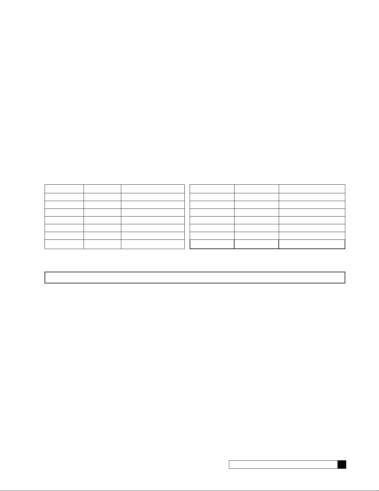
Temp. °F Temp. °C Correction Factor Temp. °F Temp. °C Correction Factor
40 4.4 2.12 75 24 1.04
45 6.7 1.90 80 27 0.95
50 10 1.71 85 29 0.86
55 13 1.54 90 32 0.79
60 16 1.39 95 35 0.72
65 18 1.26 100 38 0.66
70 21 1.14
Table 1. Temperature Correction Factors
8. Multiply the result of step 6 by the temperature correction factor. Example: 714 ml/min x 1.54 = 1099 ml/min.
NOTICE To convert ml/min to gallons per day, multiply by 0.38. For example, 1099 ml/min x 0.38 = 417 gpd.
9. Compare the current standardized flow to the initial standardized flow. If the flow has decreased by 10% or
more, it is time to clean the elements.
Example: If the initial standardized flow was 570 gpd, and the current standardized flow is 470 gpd, the flow has
decreased by 100 gpd, or 18% (100/570) = 0.18. The elements should be cleaned.
10. If the problem cannot be corrected with the troubleshooting guide and assistance is required, please have the
following information available when calling the Culligan dealer:
• Product flow rate
• Concentrate flow rate
• Feed pressure
• Product water quality
• Feed water quality
• Feed water temperature
• Prefilter outlet (and inlet if the optional prefilter inlet gauge was installed)
• Product pressure
Cat. No. 01023094
Initial Startup 13
Page 18
Accessories
A
Switch is required.
is CLOSED when water level
is below the float or pressure
in the storage tank is below
the shutof
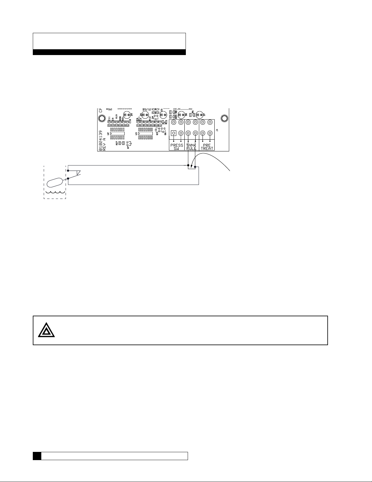
Level Control
The RO controller provides a Level Control High switch.
The Level Control connections are located on the controller board. It is labeled “TANK FULL” on the main circuit board.
This signal is Normally Closed. When OPEN it indicates that the atmospheric storage tank is FULL (or that a Pressurized
storage tank is at FULL PRESSURE.)
NORMALLY CLOSED Level
f pressure.
STORAGE TANK
The switch
LEVEL CONTROL INPUT
(Remove jumpers when installing TANK FULL
Switch)
Figure 6. RO level control switch.
Storage Tank Setup When Using a Single High Level Float Switch
Connect the level control (or pressure switch) to the TANK FULL terminals (see Figure 6). These terminals are intended
for dry-contact wiring using 18-24ga wire. Remove the installed jumper wire when making this connection.
When this event occurs, the system immediately stops making RO water and the pump will turn off and close the inlet
solenoid. It will remain off until this condition no-longer exists and then it will re-open the inlet solenoid, wait one minute
and then start the pump to return to the “make water” condition.
Storage Tank Setup When Using a Pressure Switch
When using pressurized storage, you must use a pressure switch that provides a closed signal when the tank is below the
shut off pressure, such as the switch provided in the Pressurized Water Storage Kit.
14 Culligan® Series E2 Plus Reverse Osmosis
CAUTION! Do not apply power to these terminals. Use dry contacts only.
14 Cat. No. 01023094
Page 19

Pretreatment Lockout
MVP Controller
The controller allows an external contact closure to cause the RO to go into a “pre-treat lockout” condition. This signal is
Normally Closed. When OPEN it indicates that the system should STOP because a piece of pretreatment equipment is
in a regeneration state.
When this event occurs, the system immediately stops making RO water and the pump will turn off and close the inlet
solenoid. It will remain off until this condition no-longer exists and then it will re-open the inlet solenoid, wait one minute
and then start the pump to return to the “make water” condition.
Timeclock controlled softeners, such as the Hi-Flo® 3, do not offer pretreatment lockout. If these units are used for pretreatment, they should be duplexed, or regenerated by a timeclock so that regeneration can occur when the RO unit is not
in operation.
Wiring for Hi-Flo® 2e, Hi-Flo® 55e, CSM Softeners and Filters with MVP controls
For these systems, you must add a 24 VAC relay, part number 01016156, to provide the pretreatment contact.
MVP to Relay: Connect a wire from terminal 5 of the relay to the left terminal of P8 (Aux 2) on the MVP circuit board.
Connect another wire from terminal 1 of the relay to the right terminal of P8. Refer to Figure 7. Refer to MVP Controller
manual (P/N 01017689) for programming information.
Relay to CP: Connect a pair of wires from the PRE-TREAT terminals on the CP board to terminals 2 and 4 on the relay.
Remove the installed jumper wire when making this connection.
SW6 Dip Switch
P11
Battery
P6
Motor
P9 Power
2.5VAC 24V
P7 Sol
Valve
P5
Aux1
LCD
Aux2
P8
P1
Cam
Aqua
Sensor
Comm
Flow
Meter
P3
CP Plus Controller
Cat. No. 01023094
Relay
Figure 7. MVP to CP relays.
Accessories 15
Page 20

Wiring for Hi-Flo® 2e, Hi-Flo® 55e, CSM Softeners and Filters with GBE controls
For these systems, you must add a 24 VAC relay, part number 01016156, to provide the pretreatment contact.
GBE to Relay: Connect a wire from terminal 5 of the relay to the left terminal of Aux 4 on the GBE softener/filter circuit
board. Connect another wire from terminal 1 of the relay to the right terminal of Aux 4. Refer to Figure 8.
Relay to CP: Connect a pair of wires from the PRE-TREAT terminals on the CP board to terminals 2 and 4 on the relay.
Remove the installed jumper wire when making this connection.
J5 J6
GBE SOFTENER/FILTER
J16
J17
J7
J10
CP CONTROLLER
J2
AUX OUT 4
Relay
Figure 8. GBE to CP relays.
16 Culligan® Series E2 Plus Reverse Osmosis
16 Cat. No. 01023094
Page 21

Flush Modes
Line Pressure Front Side Flush Prior to Startup
When main power is first applied to the CP controller, the controller will first wait for a one-hour delay and will then open
the RO inlet solenoid valve and waits for an additional period of one minute. During this minute, feed water under line
pressure enters the RO, passes thru the pump and flushes through the upstream (feed water side) of the membranes and
then passes to drain. When the one-minute time is elapsed, the controller checks to see if there is sufficient incoming water pressure to operate the RO. If there IS pressure, the controller turns on the main pump and the RO begins to produce
permeate water. If there IS NOT sufficient pressure, the entire process starts over beginning with the one-hour delay.
Line Pressure Front Side Flush Every Two Hours of Continuous Make Water
The unit will stop when it has been in a continuous make-water operation for two hours. The pump will remain off for one
minute. During this time, the inlet solenoid valve will remain open and the system will perform a line-pressure front-side
membrane flush to drain. At the end of the minute, the system will return to the “make-water” mode.
Cat. No. 01023094
Accessories 17
Page 22

Service and Maintenance
OFFON
POWE
POWE
POWE
POWE
POWE
Serial Numbers
The Culligan units have a serial number located directly behind the electronic controller on the side panel. Do not remove
or destroy these serial number labels.
The serial number must be referenced if the RO system requires repairs or parts replacement under warranty.
LED Status Indicators
Solution
LED Lights [
R HIGH
READY INLET
VALVE
OPEN
R HIGH
READY INLET
VALVE
OPEN
R HIGH
READY INLET
VALVE
OPEN
R HIGH
READY INLET
VALVE
OPEN
R HIGH
READY INLET
VALVE
OPEN
PUMP
ON
PUMP
ON
PUMP
ON
PUMP
ON
PUMP
ON
]
The system has power but is not making water because either the storage tank is
TDS
TDS
TDS
TDS
TDS
full or the pretreatment equipment is in pretreat lockout mode.
The system is in a one-hour delay period. These delay periods occur when either
the system has lost electrical power, or the system has lost sufficient incoming
water pressure. During this delay period you may push the RUN NOW button
located on the bottom of the control; the system will skip the remaining portion of
the delay.
The system is in start-up flush mode or timed flush mode. These modes usually
last one (1) minute.
The system is making RO water.
On systems equipped with an optional TDS probe, the system has stopped making water because the product TDS has risen above the required water quality set by the DIP switches for greater than four (4) minutes. If the system has
stopped, it might indicate that the RO membrane has failed or there might be
some other problem with the system. After resolving the problem, restart the RO
by momentarily switching the power OFF and then back ON. When the Power and Ready lights are ON, you can press the RUN NOW button. The system
should begin to produce RO water. Use a handheld TDS meter to measure the
TDS of the product water. If it remains above the specified threshold, the system
will turn back off after approximately four (4) minutes.The system will continue
running if you unplug the TDS meter from the CP+ controller board or specify a
DIP switch setting that corresponds to a higher TDS threshold level.
Troubleshooting
Problem Probable Cause Solution
1. Unit does not start. A. No power to unit. A. Check circuit breaker.
B. Low feed pressure. B. Correct low pressure condition.
C. Inlet solenoid failure C. Replace solenoid
D. Prefilter fouled. D. Replace cartridge
2. Unit running but not holding
high pressure.
18 Culligan® Series E2 Plus Reverse Osmosis
A. Pump malfunction. A. Replace pump.
B. System pressure control valve
B. Replace valve.
malfunction.
C. Concentrate flow too high. C. Check and adjust concentrate flow, re-
place tubing on A.
D. Product flow too high. D. Test modules.
18 Cat. No. 01023094
Page 23

3. Unit running but poor quality
(less than 95% rejection)
4. Low quantity of product water. A.-D. Same as 3. A.-D. Same as 3.
5. Excessive noise. A. Air in the plumbing. A. Check fittings for leaks. Purge air from
6. Inadequate product pressure
(direct feed systems)
A. Low pump pressure. A. See 2.
B. Module failure. B. Replace modules. Check product line
over pressurization.
C. Concentrate throttling valve
open.
D. Poor seal on endcap or
membrane.
E. Cold water. E. Install additional modules.
B. Misaligned pump. B. Remove pump and check for bearing
C. Harmonic vibration. C. Install a pressure regulator ahead of the
D. Low feed pressure. D. Increase feed pressure above 20 psig.
A. Low quantity of product water. A. See 4.
B. Demand for product water exceeds unit capacity.
C. Throttle valve down.
D. Check o-rings inside endcap. Replace
o-rings if necessary. Check membrane
sealing surface for debris. Check membrane O-ring and replace if necessary.
system.
wear.
prefilter.
B. Install additional modules.
Prefilter Cartridge Replacement
The prefilter cartridges should be changed when the pressure drop across the prefilter increases by 15 psi (103 kPa).
Refer to the diagram in the installation section.
CAUTION! The pressure after the prefilter should not be less than 20 psi (138 kPa), or the pump
might be damaged.
Replacing the Prefilter Cartridge
1. Disconnect power to the unit, then shut off the inlet water supply.
2. Unscrew the filter bowl.
3. Remove the old cartridge.
4. Clean the filter bowl with a damp cloth, rinse thoroughly.
5. Remove the wrappers from a new cartridge (10" P/N 01022387). Install the cartridge in the bowl, making sure it
seats in the bottom of the bowl.
6. Check the O-ring seal for dryness and cuts. Replace the seal if necessary and use silicone lube as needed.
CAUTION! Do not use petroleum-based lubricants, because they destroy the synthetic rubber
seal.
7. Screw the filter bowl back onto the filter head.
8. Turn on the inlet water supply.
Cat. No. 01023094
Service and Maintenance 19
Page 24

Membrane Replacement
Screws
Replace an element that has been damaged or cannot be cleaned. See Figure 9.
1. Disconnect power to the unit. Allow pressure to be completely relieved. Turn main feed line to RO off.
2. Remove retaining rings from both ends of all vessels.
3. Remove end caps from all vessels, with the tubing remaining in place. Note placement the caps to assure re-installation in the same orientation.
4. Remove the RO element from the housing. Note orientation of membranes to assure re-installation in same orientation. Flow direction is indicated by the arrow on the outside of the membrane vessel.
5. Check the O-ring seals on the element and end plug, and the element brine seal for damage. If an O-ring is cut
or crimped, it may have caused high flow and poor quality. Replace the O-rings and retest before replacing the
entire element.
6. Remove a new element from its plastic bag. Lightly lubricate the O-rings with a silicone-based lubricant or use a
mixture of 70% glycerin and 30% water.
CAUTION! DO NOT use a petroleum-based lubricant, because it will damage the synthetic rubber
and the membrane.
7. Make sure the brine seal is located in the direction of the incoming feed to that vessel according to the flow
arrow and the original membrane orientation.
8. Lubricate the O-ring on the end plugs with a silicone-based lubricant or use a mixture of 70 percent glycerin and
30 percent water. Re-install the end plugs in to the vessels same as the original orientation. Reinstall the retaining rings.
9. Refer to the section on Initial Startup for information on flushing the shipping solution form the new elements.
NOTE Do not forget to enter the new values for flow, pressure, temperature, and TDS.
Retaining Rings
End Cap
O-Rings
Housing
FLOW
Membrane
Brine Seal
20 Culligan® Series E2 Plus Reverse Osmosis
Figure 9. Series membrane.
20 Cat. No. 01023094
Page 25

Testing Modules
If the product flow calculations show a loss of flow, or the product quality has become poor, one or more elements will
require cleaning or replacement. Because poor performance might be due to only one element, test the product flow and
quality from individual housings.
To test each element:
1. Disconnect the product tubing from the housing to be tested.
2. Apply power to the unit, and then press the RUN NOW button. Measure the product flow and TDS from the test
element.
3. Disconnect power to the unit and reinstall the tubing.
4. Continue testing the elements as needed to determine which should be cleaned or replaced.
Cleaning Modules
During the operation of any reverse osmosis system, dissolved solids and particulate matter are concentrated inside the
module element. If these contaminants are present in relatively low concentrations, the concentrate flow from the system
flushes them to drain. In most cases, water pretreatment such as filters and softeners will prevent the deposit of these
contaminants.
When these deposits occur, there will be a decrease in the product water flow and quality. When these symptoms become excessive, the modules must be cleaned before they are permanently damaged.
To determine when cleaning is needed, compare the current system performance to the performance of the system when
the reverse osmosis elements were new. Use Table 2 to obtain data and compare the performance of the system, “new”
and “now” (record the data in pencil).
Test Data Feed Product Concentrate
New Now New Now New Now
Flow (gpm)
TDS (ppm)
Pressure (psi)
Temp. (°F)
Table 2. System performance—new vs. present.
NOTICE If new data is not available, use the specifications listed earlier in these instructions. However,
keep in mind that the new elements may have exceeded these specifications, so performance may
have decreased even if the unit still exceeds specifications.
In addition to differences in product flow and quality (TDS), determine whether there were any changes in concentrate water flow, feed water TDS, feed water temperature and feed or product pressures. Changes in these values provide clues
to indicate the cause of any problems with the product water.
If there were changes in feed water temperature or pressure, the product water flow rates will have to be converted to flow
rates under standard conditions (77° F and 100 psig) in order for any comparison to be valid. Refer to the Product Flow
Calculation section to calculate flow rates under standard conditions, then compare the converted values. A decrease in
the product water flow may have been due only to a decrease in temperature or pressure, in which case cleaning would
not be indicated.
If any change in the performance of the elements was not due to a change in operating conditions, it may be time to clean
the elements. In general clean the elements:
1. When the product flow rate decreases by 10% (or when the feed pressure must be increased by 10% to main-
tain the same product flow), or
2. When the percent of rejection decreases below specification.
Cat. No. 01023094
Service and Maintenance 21
Page 26

NOTICE Replace the prefilter cartridges if they are discolored by iron.
NOTICE Because strong chemicals are used to clean the elements, maintenance cleaning is not recom-
mended. If the elements need to be cleaned frequently (more than twice a year), the pretreatment
may be inadequate. Obtain a current water analysis and test the Silt Density Index and the Total
Chlorine level of the water on-site to review what changes in pretreatment may be needed.
When cleaning is required, the type of material which is fouling the element should be identified, if possible. Refer to
Table 3 to determine the possible causes of the performance change.
Percent
Rejection
Low Hardness Scale Hardness Scale (light) or Iron Membrane Damage
High Silt or Biofouling — Membrane Damage (light)
For example, if the product flow is low but the percent rejection is normal, the likely causes of the problem are silt or
biofouling. Please note that if the product flow rate has increased (with no increase in temperature or pressure) the likely
reason is damage to the membrane, which cannot be repaired by cleaning.
Once the foulant has been identified, choose the recommended cleaning chemical(s) from Table 4.
Membrane Problem Cleaning Chemical
Hardness Scale Hydrochloric acid, phosphoric acid
Iron Hydrochloric acid, phosphoric acid
Silt Phosphoric acid and sodium hydroxide
Biofouling Phosphoric acid and sodium hydroxide
Because phosphoric acid can be used by itself or in combination with sodium hydroxide to clean almost all types of foulants, it is generally recommended over hydrochloric acid when choosing a “stock” acid.
NOTICE Some municipal surface water supplies are treated with alum. Aluminum fouling results in low flow
and, occasionally, in low rejection. If aluminum fouling is suspected, use only hydrochloric acid.
Use a pH meter to prepare acid and caustic solutions, and to monitor pH changes as the solutions react with any foulants.
Materials required:
1. Solution tank (50 gallon capacity, minimum), to prepare and store the chemical solution.
2. Tank stand, to elevate solution tank to level above pump.
Low Normal High
Table 3. Performance change possible causes.
Table 4. Recommended membrane cleaning chemicals.
Flow
CAUTION! The bottom of the tank must be higher than the pump on the RO unit to prevent cavita-
tion of the pump when solution is drawn from the tank.
3. Tubing 1/2” O.D. to connect cleaning adapter ahead of Pre-filter.
4. A pH meter.
5. A pre-filter cartridge (P/N 00955004).
Before proceeding record the “NOW” values in Table 2.
22 Culligan® Series E2 Plus Reverse Osmosis
22 Cat. No. 01023094
Page 27

Prepare the Equipment for Cleaning
1. Turn the unit power off.
2. Place the solution tank on the tank stand. Connect the tubing to the cleaning adapter then place the other end
of the tubing at the bottom of the solution tank.
NOTICE The tubing length should be as short as possible to prevent excessive pressure drop. Cut the tub-
ing as required to minimize the length.
3. Remove the product tubing from the service connection and place the end in the solution tank. The concentrate
tubing should still be directed to drain.
4. Replace the Pre-filter cartridge.
5. Apply power to the unit, and then press the RUN NOW button.
6. Fill the tank with 30-40 gallons of RO product water.
CAUTION! DO NOT turn on the RO system unless water can flow from the product and waste
lines.
NOTE Soft water is an acceptable substitute for RO water. When the solution tank is filled, direct the prod-
uct tubing to drain. Next, open the pump system pressure control valve until the system pressure is
approximately 50 psig.
7. Turn the unit power off. Remove wires from Pressure switch terminals and install a jumper wire across those
two terminals.
8. Open the cleaning valve to allow feed water to displace air in the cleaning tubing, then close the inlet water
shutoff valve.
Step 1: Clean the Unit
1. Apply power to the unit, and then press the RUN NOW button.
CAUTION! If the pump is noisy, cavitation is occurring and the pump will be damaged. Turn the
power switch OFF and check for any obstructions to flow. Reduce the pump pressure
as required to prevent cavitation.
2. Record the pump pressure and measure the product water flow at low pressure. This flow will be used to esti-
mate if cleaning has been successful. Turn the unit power off.
3. Add enough acid to the solution tank until the pH is between 2.0 and 2.5.
NOTE If the foulant to be removed is silt or a biofilm, use phosphoric acid.
WARNING! Acid and Sodium Hydroxide are strong chemicals that must be handled carefully to
avoid injury. Wear protective clothing and have a source of water nearby to flush any
spills.
CAUTION! Local codes may prohibit the discharge of acid and caustic solutions to drain. If
necessary, an extra tank can be used to neutralize the solutions before discharging to
drain.
4. Apply power to the unit, and then press the RUN NOW button. After approximately 5 gallons have been drawn
from the solution tank, turn the unit power off.
5. Allow elements to soak for 15 minutes. Apply power to the unit, and then press the RUN NOW button. Draw
another 5 gallons from the solution tank. Turn the unit power off.
Cat. No. 01023094
Service and Maintenance 23
Page 28

6. Remove the end of concentrate tubing from the drain and place it in the solution tank.
7. Apply power to the unit, and then press the RUN NOW button. Allow the acid solution to circulate for 30 minutes. During recirculation, monitor the pH of the solution. If the pH rises above 3.0, add acid to reduce the pH to
2.0.
CAUTION! The temperature of the chemical solution will rise as it is recirculated. If the temper-
ature exceeds 95°F, turn the power switch to OFF and allow the solution to cool to
prevent damage to the RO elements.
NOTE A plastic gallon jug filled with ice may be placed in the solution to cool it.
8. When 30 minutes have passed, adjust the system pressure to the pressure recorded in Step 9. Measure the
product flow rate, then compare this flow to the flow recorded in Step 9. If cleaning is successful a noticeably
higher product flow should now be observed.
9. Turn the unit power off. If the cleaning was for removal of hardness scale or iron only, go to “Step 3: Finish
Cleaning Procedure” on page 25.
Step 2: Clean Silt or Biofouling
1. If the cleaning was for silt or biofouling, take a 250 ml sample of phosphoric acid solution and carefully add
sodium hydroxide until the pH is at least 12. If the solution turns cloudy, it contains hardness and/or iron.
Discard the contaminated acid and prepare a fresh 30 gallons of phosphoric acid solution.Add sodium hydroxide
to the phosphoric acid solution. The pH of the solution should be increased to 11.0-11.5.
NOTE The result is an alkaline solution of tri-sodium phosphate (TSP), a common ingredient in detergents.
2. If the solution remains clear, direct the concentrate tubing to drain, apply power to the unit, and then press the
RUN NOW button. Check that the unit is drawing chemical solution.
CAUTION! If the pump is noisy, cavitation is occurring and the pump will be damaged. Turn the
unit power off and check for any obstructions to flow. Reduce the pump pressure as
required to prevent cavitation.
3. After approximately 5 gallons have been drawn from the solution tank, turn the unit power off.
4. Allow the elements to soak for 15 minutes. Apply power to the unit, and then press the RUN NOW button. Draw
another 5 gallons from the solution tank. Turn the unit power off.
5. Remove the end of concentrate tubing from the drain and place it in the solution tank. Apply power to the unit,
and then press the RUN NOW button. Allow the alkaline solution to circulate for 30 minutes. During recirculation
monitor the pH of the solution. If the pH drops below 10.0 add sodium hydroxide to increase the pH to 11.5.
NOTE If the caustic solution becomes dark brown (like coffee), it probably is saturated with organic material.
Discard the solution and prepare a fresh batch of phosphoric acid and sodium hydroxide.
For more accurate testing, use a Hach Model DE-2 detergent test kit or equivalent to ensure that the
product water is less than 0.05 ppm detergent.
A plastic gallon jug filled with ice may be placed in the solution tank to cool the solution.
CAUTION! The temperature of the chemical solution will rise as it is recirculated. If the temper-
ature exceeds 95°F, turn the unit power off and allow the solution to cool to prevent
damage to the RO elements.
24 Culligan® Series E2 Plus Reverse Osmosis
24 Cat. No. 01023094
Page 29

Step 3: Finish Cleaning Procedure
1. When 30 minutes have passed, adjust the system pressure to the pressure recorded during low pressure.
Measure the product flow rate, then compare this flow to the flow recorded during low pressure. If cleaning is
successful a noticeably higher product flow should now be observed.
2. Turn the unit power off. Remove the concentrate and product tubing from the solution tank and direct them both
to drain. Apply power to the unit, and then press the RUN NOW button to draw most of the remaining cleaning
solution from the tank.
CAUTION! Do not allow the unit to draw air from the tank, or the pump will be damaged.
3. Turn the unit power off. Close the cleaning valve, reconnect the wires to the pressure switch, then open the
feed water valve.
4. Apply power to the unit, press the RUN NOW button, and then flush the cleaning solution from the unit for 30
minutes or until the pH levels of the concentrate water and the product water remain constant.
CAUTION! Soft water must be used to flush the caustic solution, or hardness will precipitate. If
soft water is not available, use temporary portable exchange softener tanks.
5. Adjust the system pressure to the normal value. Measure all flows, TDS levels, pressures, and temperature.
Compare these values with the “new” and “now” values to determine if cleaning has been successful. If cleaning
has not been successful, contact the service department at Culligan International Company for suggestions on
alternate cleaning chemicals. If cleaning has been successful, note which chemicals were effective. Use the
same chemical(s) when the unit is cleaned again.
6. Replace the Pre-filter cartridge.
7. After cleaning and rinsing have been completed, connect the product tubing to the service line. Remove the
jumper installed and reconnect the pressure switch. Rinse the cleaning tank and tubing with fresh water.
Cat. No. 01023094
Service and Maintenance 25
Page 30

Flow Diagram
Process Flow Diagram
CONCENTRATE
HCV-3 HCV-2
PRODUCT
UNIT
CV-1
UNIT
TDS
TDS
FI
FI-2
MEMBRANEHOUSING(S)
PI
PI-1
HCV-1
PUMP/MOTOR
PS
CONTROLLER
26 Culligan® Series E2 Plus Reverse Osmosis
S
FI
FI-1 SV-1 PS-1
FILTER
UNIT
CIP
SUPPLIED)
PRESSURE
(CUSTOMER
REGULATOR
VALVE
MANUAL
SHUTOFF
SUPPLIED)
(CUSTOMER
FEED
LEGEND
PI PRESSURE INDICATOR
PS PRESSURE SWITCH
HCV HAND CONTROLVALVE
SV SOLENOID VALVE
TDSTDS PROBE
FI FLOW INDICATOR
FS FLOW SENSOR
CV CHECKVALVE
CIPCLEAN IN PLACE
ELECTRICAL
CONNECTION TO PROCESS OR INSTRUMENTSUPPLY
26 Cat. No. 01023094
Page 31

Series E2 Plus Wiring Diagram
A
Switch is required.
is CLOSED when water level
is below the float or pressure
in the storage tank is below
the shutof
BROWN
115/230
VOLTAGE
SELECTOR
GREEN
WHITE
BLACK
Wiring Diagram
GREEN
115V/230V,
60Hz/50Hz,1PH
INCOMING POWER
RED
WHITE
GREEN
PRESSURIZED
STORAGE KIT
D1013880
SV4
PS
NORMALLY CLOSED Level
STORAGE TANK
The switch
f pressure.
BLACK
WHITE
BLACK
RED
LEVEL CONTROL INPUT AND
PRETREATMENT LOCKOUT INPUT
(Remove jumpers when installing TANK FULL
Switch or Pretreatment Lockout Connection)
RED
WHITE
NOTE: The inlet pressure switch is CLOSED when the
pressure is sufficient for the RO to run.
POWER CORD, MOTOR
GREEN
CABLE, SOLENOID
PRETREATMENT LOCKOUT SWITCH
A NORMALLY CLOSED switch is required. This
switch is OPEN during regeneration, but is
CLOSED at all other times.
CABLE, INLET PRESSURE SWITCH
B:LACK
Cat. No. 01023094
Figure 10. Series wiring diagram.
Wiring Diagram 27
Page 32

E2 Plus RO Parts Diagrams and Lists
Series E2 Plus Major Components and Water Connections, 208-230V/ 60
Hz, U.S.
Filter
2
Arrays
Filter
Arrays
3
Feed and Product
Flow Meters
Waste and Recirculation
Control Valves
Pump Pressure
Gauge
Front Panel
Assembly
Prefilter
Throttling
Pump
Figure 11. E2 Plus RO front view.
Item Description Part Number
E2-2 Plus E2-3 Plus E2-4 Plus E2-5 Plus E2-6 Plus
— RO System, E2 Plus 01022839 01022840 01022841 01022842 01022843
1 Assembly, Generic, E2 Plus 01023797
Assembly, Side, Pump, E2 Plus 01023794
Assembly, Side, Filter, E2 Plus 01023795
2 Filter Array, 2-2 01021963 01021963
3 Filter Array, 2-1 01021927 01021927
2 Filter Array, 3-2 01021962
3 Filter Array, 3-1 01021928 01021928 01021928
Membrane, 4”x40” 01024290
(2)
8 Cartridge Filter, 5 micron, 10” BB 00403232
18 Gate Valve 01021544
Controller 01024598
Piping Feed 01022959
Piping Concentrate 01022958
Piping Product 01021941
01024290
(3)
01024290
(4)
Valve
01024290
(5)
01024290
(6)
1
28 Culligan® Series E2 Plus Reverse Osmosis
28 Cat. No. 01023094
Page 33

Front Panel Assembly, 208-230V/ 60 Hz, U.S.
1
5
5
4
7
6
Figure 12. E2 Plus front panel assembly.
8
3
Item Part No. Description Qty
— 01022957 FRONT PANEL ASSEMBLY E2 PLUS RO
1
2 01022959 PIPING ASSEMBLY E2 PLUS FEED 1
3 01022958 PIPING ASSEMBLY E2 PLUS CONCENTRATE 1
4 01022978 Pressure Gauge,0-200 PSI,2-1/2",1/4"CBM 1
5 01022233 ROTAMETER 0-10 GPM 2
6 01024598 Assembly, CP+ Control, E2+ 1
7 01021316 CABLE, 9.4 MINI DIN CONNECTOR 1
— 01022319 CORD, M2, MOTOR POWER 1
8 01024302 Switch,Pressure,Adj,6-30PSI 1
— FRONT PANEL E2 PLUS
1
2
Cat. No. 01023094
E2 Plus RO Parts Diagrams and Lists 29
Page 34

Feed Assembly, 208-230V/ 60 Hz, U.S.
4
6
2
9
10
9
10
3
14
4
6
3
8
9
11
5
4
11
15
1
7
13
12
Figure 13. E2 Plus feed assembly.
Item Part No. Description Quantity
— 01022959 PIPING ASSEMBLY E2 Plus FEED
1 01017302 SOLENOID VALVE, 3/4",NC,220V/50–60HZ 1
2 — NIPPLE,3/4X3,PVC SCH.80,PE 1
3 — NIPPLE,3/4X4,PVC SCH.80,PE 2
4 — Nipple,3/4x2,PVC Sch.80,TOE 3
5 — Nipple,3/4x2-1/2,PVC Sch.80,TOE 1
6 — Tee,3/4",Socket,PVC Sch.80 2
7 — Bushing,3/4x1/4,TxT,PVC Sch.80 1
8 — Bushing,3/4x1/2,SxT,PVC Sch.80 1
9 — Elbow,3/4",SxS,PVC Sch.80 3
10 — Elbow,3/4",TxT,PVC Sch.80 2
11 — ADAPTER HOSE BARB 3/4" X 3/4" NPTE 2
12 — Fitting,Male Connector,1/2Tx1/2NPTE,PI 1
13 01021543 Check Valve 1
14 — Nipple,1/2xClose,PVC Sch.80,TBE 1
15 — Fitting,Stem Elbow,1/2Tx1/2Stem,PI 1
30 Culligan® Series E2 Plus Reverse Osmosis
30 Cat. No. 01023094
Page 35

Product Assembly, 208-230V/ 60 Hz, U.S.
4
1
5
1
1
3
Figure 14. E2 Plus product piping assembly.
Item Part No. Description Quantity
— 01021941 Piping Assembly Product
1 — Tee, Threaded, .50 PVC Sch.80, NPT 2
3
4 — Nipple,1/2x5,PVC Sch.80,TBE 1
5 — Fitting,Male Adaptor,1/2" 2
— Nipple,1/2xClose,PVC Sch.80,TBE
1
5
Cat. No. 01023094
E2 Plus RO Parts Diagrams and Lists 31
Page 36

Concentrate Piping Sub-Assembly, 208-230V/ 60 Hz, U.S.
Figure 15. E2 Plus concentrate piping sub-assembly.
Item Part No. Description Qty.
— 01022958 Piping Assembly E2 Plus Concentrate
1 01021539 Valve,Needle,1/2" Brass 2
2 — Fitting,Male Connector,1/2Tx1/2NPTE,PI 4
3 — Fitting,Stem Elbow,1/2Tx1/2Stem,PI 2
4 — Fitting,Union Tee,1/2T,PI 1
5 00901801 Tubing,1/2",PE,Natural -
32 Culligan® Series E2 Plus Reverse Osmosis
32 Cat. No. 01023094
Page 37

Membrane Vessel, 208-230V/ 60 Hz, U.S.
1
END CAP
RETAINING RINGS
SCREWS
2
O-RINGS
FLOW
3
GASKET END
NOTE:
1 Does NOT
Include 2
4
Item Part No. Description Per Vessel
1 01021540 Housing, Filter, FRP 4" End Port 1
2 01024290 Membrane, 4"x40" 1
3 01023073 End Plug Assembly, 4" 2
4 P1021848 O-Ring Head Seal 4”, 20 pack 2
1
Housing comes with everything, except the membrane.
4
Each vessel requires two (2) individual o-rings NOT two (2) packets of o-rings.
Figure 16. E2 Plus membrane vessel.
Cat. No. 01023094
E2 Plus RO Parts Diagrams and Lists 33
Page 38

Membrane Assembly, E2-2 Plus and E2-4 Plus, 208-230V/ 60 Hz, U.S.
This assembly is used on the E2-2 and E2-4. It is mounted on the right side (facing unit) of an E2-4.
13
9
10
12
4
5
8
11
7
10
12
11
2
9
5
20
7
8
1
6
Top View
397
Bottom View
Figure 17. E2 Plus Membrane Assembly.
NOTE Product water exits center holes in end cap. Feed and concentrate enter the outer holes.
Item Part No. Description Qty
— 01021927 Filter Array, 2-1
1 — Mount Filter, 2 2
2 01021540 Housing, Filter, FRP 4" End Port 2
3 — Plug, 1/2", Threaded, PVC Sch.80 2
4 01021090 Pipe, PEX, 1/2" 1
5 — Fitting, PEX, Stem Elbow, 1/2" 2
6 — Fitting, Stem Elbow, 1/2Tx1/2Stem, PI 1
7 — Bushing, 3/4x1/2, TxT, PVC Sch. 80 3
8 — Fitting, PEX, Male Connector, 1/2" 2
9 — Fitting, Male Connector, 1/2Tx1/2NPTE, PI 3
10/11 00901801 Tubing, 1/2", PE, Natural —
12 — Fitting, Union Elbow, 1/2T, PI 2
13 — Fitting, Union Tee, 1/2T, PI 1
14 — .75 x .75 NPT Fitting, Barbed 1
15 — Elbow, 3/4", TxT, PVC Sch.80 1
16 — Nipple, 3/4x3, PVC Sch.80, TBE 1
18 — Decal, Flow Arrow 2
19 — Decal, Culligan Script 2
20 01024102 Saddle Strap Kit (2 straps, 2 saddles, 4 screws) 2
14
15
3
16
34 Culligan® Series E2 Plus Reverse Osmosis
34 Cat. No. 01023094
Page 39

Membrane Assembly, E2-4 Plus and E2-5 Plus, 208-230V/ 60 Hz, U.S.
This assembly is used on the E2-4 & E2-5 as the left bank (when facing unit) of membranes.
Top View
10
8
11
7
7
10
8
6
6
4
6
5
9
456
18
10
11
12
11
10
9
Bottom View
Figure 18. E2-4 or E2-5 Plus Membrane Assembly.
Item Part No. Description Qty
— 01021963 Filter Array, 2-2
1 — Mount Filter 2 2
2 01021540 Housing, Filter, FRP 4" End Port 2
3 — Plug, 1/2", Threaded, PVC Sch.80 2
4 — Fitting, Stem Elbow, 1/2Tx1/2 Stem, PI 4
5 — Bushing, 3/4x1/2, TxT, PVC Sch.80 4
6 — Fitting, Male Connector, 1/2Tx1/2NPTE, PI 6
7 00901801 Tubing, 1/2", PE, Natural —
10 — Fitting, Union Elbow, 1/2T, PI 2
11 — Fitting, Union Tee, 1/2T, PI 1
12 01008007 Element RO 4" Dia. x 40" 2
13 — Decal, Flow Arrow 2
14 — Decal, Culligan Script 2
15 01024102 Saddle Strap Kit (2 straps, 2 saddles, 4 screws) 2
12
11
9
Cat. No. 01023094
E2 Plus RO Parts Diagrams and Lists 35
Page 40

Membrane Assembly, E2-3 Plus, E2-5 Plus, and E2-6 Plus, 208-230V/ 60
Hz, U.S.
This assembly is used on the E2-3 Plus, E2-5 Plus, and E2-6 Plus. It is mounted on the right side (when facing unit) of the
E2-5 Plus and E2-6 Plus.
14
5
10
11
12
13
9
6
8
9
7
9
6
11
13
Top View
10
12
4
5
13
21
9
6
1
6
7
2
7
5
Bottom View
3
4
3
5
3
7
Figure 19. E2-3, E2-5 or E2-6 Plus Membrane Assembly.
Item Part No. Description Qty
— 01021928 Filter Array, 3-1
1 — Mount Filter 3 2
2 01021540 Housing, Filter, FRP 4" End Port 3
3 — Plug, 1/2", Threaded, PVC Sch.80 3
4 01021090 Pipe, PEX, 1/2" —
5 — Fitting, PEX, Stem Elbow, 1/2" 4
6 — Bushing, 3/4x1/2, Txt, PVC Sch.80 5
7 — Fitting, PEX, Male Connector, 1/2" 4
8 — Fitting, Stem Elbow, 1/2Tx1/2Stem, PI 1
9 — Fitting, Male Connector, 1/2Tx1/2NPTE, PI 4
10 00901801 Tubing, 1/2", PE, Natural —
11 — Fitting, Union Tee, 1/2T, PI 2
12 — Fitting, Union Elbow, 1/2T, PI 2
15 — Adapter, Hose Barb, 3/4"x3/4" NPTE 1
16 — Elbow, 3/4", TxT, PVC Sch.80 1
17 — Nipple, 3/4x3, PVC Sch.80 TBE 1
18 01008007 Element RO, 4" Dia x 40" 3
19 — Decal, Culligan Script 3
20 — Decal, Flow Arrow 3
21 01024102 Saddle Strap Kit (2 straps, 2 saddles, 4 screws) 3
6
15
17
16
36 Culligan® Series E2 Plus Reverse Osmosis
36 Cat. No. 01023094
Page 41

Membrane Assembly, E2-6 Plus, 208-230V/ 60 Hz, U.S.
This assembly is used on the E2-6 Plus and is mounted on the left side when facing the unit.
10
11
10
5
7
8
11
8
9
6
6
4
9
6
5
5
7
6
6
4
Top View
15
4
3
Bottom View
45 6
7
5
6
4
Figure 20. E2-6 Plus Membrane Assembly.
Item Part No. Description Qty
— 01021962 Filter Array, 3-2
1 — Mount Filter 3 2
2 01021540 Housing, Filter, FRP 4" End Port 3
3 — Plug, 1/2", Threaded, PVC Sch.80 3
4 — Fitting, Stem Elbow, 1/2Tx1/2Stem, PI 6
5 — Bushing, 3/4x1/2, Txt, PVC Sch.80 6
6 — Fitting, Male Connector, 1/2Tx1/2NPTE, PI 9
7 00901801 Tubing, 1/2", PE, Natural —
8 — Fitting, Union Tee, 1/2T, PI 2
9 — Fitting, Union Elbow, 1/2T, PI 2
12 01008007 Element RO, 4" Dia x 40" 3
13 — Decal, Culligan Script 3
14 — Decal, Flow Arrow 3
15 01024102 Saddle Strap Kit (2 straps, 2 saddles, 4 screws) 3
Cat. No. 01023094
E2 Plus RO Parts Diagrams and Lists 37
Page 42

CP Plus Controller Assembly, 208-230V/ 60 Hz, U.S.
15
21
8
1
17 10
18
14
5
3
11
16
9
23
24
22
6
4
7
12
2
Figure 21. CP Plus Controller assembly.
Item Part No. Description Qty
— 01024598 Controller, CP Plus, Assembly 1
1 01024191 Enclosure, Global Control 1
8 01023445 Plug, Watertight, .625 Dia. 3
9 01024179 Cord, NEMA, 5-15 14/3, 108"L 1
10 01016142 Locknut, 1/2", Nylon 2
13 01014886 Plug Dome .875 Hole HEYC 2
38 Culligan® Series E2 Plus Reverse Osmosis
38 Cat. No. 01023094
Page 43

Appendix A Series E2 Plus International
E2 Plus International Specifications
Model
Part Number
Nominal Capacity, GPD* 3360 4870 6300 7560 8400
Dimensions, Series E2 Plus Units
Width - in [mm] 25.8 [655.3]
Depth - in [mm] 29.3 [744.2]
Height - in [mm] 52.6 [1336]
Operating Weight lb [kg] 198 [89.1] 228 [102.6] 258 [116.1] 288 [129.6] 318 [143.1]
Unit Connections
Inlet (NPT) 3/4 NPT
Product (Tube) 1/2 NPT
Concentrate (Tube) 0.5"
Electrical
Motor Horsepower (hp) 1.0
Power Requirement (VAC/Hz/phase) 220/50/1
Full Load Current (amp) 9.4
Hydraulic - Prefilter
Housing Quantity 2 3 4 5 6
Cartridge Quantity 1
Cartridge Size - in [mm] 10 [254]
Cartridge Rating (micron) 5
Hydraulic - RO
RO Housing Quantity 2 3 4 5 6
RO Element Quantity 2 3 4 5 6
RO Element Length - in [mm] 40 [1016] 40 [1016] 40 [1016] 40 [1016] 40 [1016]
Product Flow - gpm [L/min]* 2.34 [8.84] 3.39 [12.81] 4.38 [16.56] 5.25 [19.87] 5.83 [22.08]
Concentrate Flow - gpm [L/min]* 2.34 [8.84] 2.26 [8.53] 2.91 [11.04] 1.75 [6.63] 1.94 [7.36]
Recovery (%)*
Design 50 60 60 75 75
Minimum 40 50 50 60 60
Maximum Module Feed Pressure psig [kPa] 160 [1103]
Nominal Module Feed Pressure psig [kPa] 140 [965]
Maximum Product Pressure psig [kPa] 40 [276]
Operating Temperature °F [°C] 40–100 [4–38]
Inlet Pressure
Minimum, dynamic psig [kPa] 20 [103]
Maximum, dynamic psig [kPa] 40 [276]
Maximum, static psig [kPa] 100 [689]
Required Inlet Feed Flow gpm [L/min] 4.67 [17.6] 5.64 [21.33] 7.29 [27.64] 7.00 [26.46] 7.78 [29.48]
Pump Flow @ 125 psi gpm [Lmin] 9.24 [34.94] 11.0 [41.6] 11.0 [41.6] 11.0 [41.6] 11.0 [41.6]
Salt Rejection, Nominal (%) 97 97 97 96 95
†Calculated using a 0.85 fouling factor
*Nominal capacity based on new RO membranes operating on a properly pretreated feed water of 500 ppm TDS as NaCl,
77 °F (25 °C), Silt Density Index (SDI) below 3, and supplying water to atmosphere. Productivity will vary depending on
the actual feed water quality and temperature.
E2 Plus-2 E2 Plus-3 E2 Plus-4 E2 Plus-5 E2 Plus-6
01023850 01023851 01023852 01023853 01023854
Cat. No. 01023094
Series E2 Plus International 39
Page 44

Series E2 Plus Major Components and Water Connections, 220V/ 50 Hz,
International
Filter
2
Arrays
Filter
3
Arrays
Feed and Product
Flow Meters
Waste and Recirculation
Control Valves
Pump Pressure
Gauge
Front Panel
Assembly
Prefilter
Throttling
Pump
Figure 22. E2 Plus RO front view.
Item Description Product Number
E2-2 Plus E2-3 Plus E2-4 Plus E2-5 Plus E2-6 Plus
— RO System, E2 Plus, 50 Hz 01023850 01023851 01023852 01023853 01023854
1 Assembly, Generic, E2 Plus, 50 Hz 01023886 01023886 01023886
Assembly, Side, Pump, E2 Plus,50Hz 01023887 01023887 01023887
Assembly, Side, Filter, E2 Plus, 50 Hz 01025993
2 Filter Array, 2-2 01021963 01021963
3 Filter Array, 2-1 01021927 01021927
2 Filter Array, 3-2 01021962
3 Filter Array, 3-1 01021928 01021928 01021928
Membrane, 4”x40” 01024290
(2)
8 Cartridge Filter, 5 micron, 10”BB 00403232
18 Gate Valve 01021544
Controller 01024598
Piping Feed 01022959
Piping Concentrate 01022958
Piping Product 01021941
01024290
(3)
01024290
(4)
Valve
01024290
(5)
01024290
(6)
1
40 Culligan® Series E2 Plus Reverse Osmosis
40 Cat. No. 01023094
Page 45

Front Panel Assembly, 220V/ 50 Hz, International
1
5
5
4
7
6
Figure 23. E2 Plus front panel assembly.
8
3
Item Part No. Description Qty
— 01022957 FRONT PANEL ASSEMBLY E2 PLUS RO
1
2 01022959 PIPING ASSEMBLY E2 PLUS FEED 1
3 01022958 PIPING ASSEMBLY E2 PLUS CONCENTRATE 1
4 01022978 Pressure Gauge,0-200 PSI,2-1/2",1/4"CBM 1
5 01022233 ROTAMETER 0-10 GPM 2
6 01024598 Assembly, CP+ Control, E2+ 1
7 01021316 CABLE, 9.4 MINI DIN CONNECTOR 1
— 01022319 CORD, M2, MOTOR POWER 1
8 01024302 Switch,Pressure,Adj,6-30PSI 1
— FRONT PANEL E2 PLUS
1
2
Cat. No. 01023094
Series E2 Plus International 41
Page 46

Feed Assembly, 220V/ 50 Hz, International
4
6
2
9
10
9
10
3
14
4
6
3
8
9
11
5
4
11
15
1
7
13
12
Figure 24. E2 Plus feed assembly.
Item Part No. Description Quantity
— 01022959 PIPING ASSEMBLY E2 Plus FEED
1 01017302 SOLENOID VALVE, 3/4",NC,220V/50–60HZ 1
2 — NIPPLE,3/4X3,PVC SCH.80,PE 1
3 — NIPPLE,3/4X4,PVC SCH.80,PE 2
4 — Nipple,3/4x2,PVC Sch.80,TOE 3
5 — Nipple,3/4x2-1/2,PVC Sch.80,TOE 1
6 — Tee,3/4",Socket,PVC Sch.80 2
7 — Bushing,3/4x1/4,TxT,PVC Sch.80 1
8 — Bushing,3/4x1/2,SxT,PVC Sch.80 1
9 — Elbow,3/4",SxS,PVC Sch.80 3
10 — Elbow,3/4",TxT,PVC Sch.80 2
11 — ADAPTER HOSE BARB 3/4" X 3/4" NPTE 2
12 — Fitting,Male Connector,1/2Tx1/2NPTE,PI 1
13 01021543 Check Valve 1
14 — Nipple,1/2xClose,PVC Sch.80,TBE 1
15 — Fitting,Stem Elbow,1/2Tx1/2Stem,PI 1
42 Culligan® Series E2 Plus Reverse Osmosis
42 Cat. No. 01023094
Page 47

Product Assembly, 220V/ 50 Hz, International
4
1
5
1
1
3
Figure 25. E2 Plus product piping assembly.
Item Part No. Description Quantity
— 01021941 Piping Assembly Product
1 — Tee, Threaded, .50 PVC Sch.80, NPT 2
3
4 — Nipple,1/2x5,PVC Sch.80,TBE 1
5 — Fitting,Male Adaptor, 1/2" 2
— Nipple,1/2xClose,PVC Sch.80,TBE
1
5
Cat. No. 01023094
Series E2 Plus International 43
Page 48

Concentrate Piping Sub-Assembly, 220V/ 50 Hz, International
Figure 26. E2 Plus concentrate piping sub-assembly.
Item Part No. Description Qty.
— 01022958 Piping Assembly E2 Plus Concentrate
1 01021539 Valve,Needle,1/2" Brass 2
2 — Fitting,Male Connector,1/2Tx1/2NPTE,PI 4
3 — Fitting,Stem Elbow,1/2Tx1/2Stem,PI 2
4 — Fitting,Union Tee,1/2T,PI 1
5 00901801 Tubing,1/2",PE,Natural —
44 Culligan® Series E2 Plus Reverse Osmosis
44 Cat. No. 01023094
Page 49

Membrane Vessel, 220V/ 50 Hz, International
1
END CAP
RETAINING RINGS
SCREWS
2
O-RINGS
FLOW
3
GASKET END
NOTE:
1 Does NOT
Include 2
4
Item Part No. Description Per Vessel
1 01021540 Housing, Filter, FRP 4" End Port 1
2 01024290 Membrane, 4"x40" 1
3 01023073 End Plug Assembly, 4" 2
4 P1021848 O-Ring Heal Seal 4”, 20 pack 2
1
Housing comes with everything, except the membrane.
4
Each vessel requires two (2) individual o-rings NOT two (2) packets of o-rings.
Figure 27. E2 Plus membrane vessel.
Cat. No. 01023094
Series E2 Plus International 45
Page 50

Membrane Assembly, E2-2 Plus and E2-4 Plus, 220V/ 50 Hz, International
This assembly is used on the E2-2 and E2-4. It is mounted on the right side (facing unit) of an E2-4.
13
9
10
12
4
5
8
11
7
10
12
11
2
9
5
20
7
8
1
6
Top View
397
Bottom View
Figure 28. E2 Plus Membrane Assembly.
NOTE Product water exits center holes in end cap. Feed and concentrate enter the outer holes.
Item Part No. Description Qty
— 01021927 Filter Array, 2-1
1 — Mount Filter, 2 2
2 01021540 Housing, Filter, FRP 4" End Port 2
3 — Plug, 1/2", Threaded, PVC Sch.80 2
4 01021090 Pipe, PEX, 1/2" 1
5 — Fitting, PEX, Stem Elbow, 1/2" 2
6 — Fitting, Stem Elbow, 1/2Tx1/2Stem, PI 1
7 — Bushing, 3/4x1/2, TxT, PVC Sch. 80 3
8 — Fitting, PEX, Male Connector, 1/2" 2
9 — Fitting, Male Connector, 1/2Tx1/2NPTE, PI 3
10/11 00901801 Tubing, 1/2", PE, Natural —
12 — Fitting, Union Elbow, 1/2T, PI 2
13 — Fitting, Union Tee, 1/2T, PI 1
14 — .75 x .75 NPT Fitting, Barbed 1
15 — Elbow, 3/4", TxT, PVC Sch.80 1
16 — Nipple, 3/4x3, PVC Sch.80, TBE 1
18 — Decal, Flow Arrow 2
19 — Decal, Culligan Script 2
20 01024102 Saddle Strap Kit (2 straps, 2 saddles, 4 screws) 2
14
15
3
16
46 Culligan® Series E2 Plus Reverse Osmosis
46 Cat. No. 01023094
Page 51

Membrane Assembly, E2-4 Plus and E2-5 Plus, 220V/ 50 Hz, International
This assembly is used on the E2-4 & E2-5 as the left bank (when facing unit) of membranes.
Top View
10
8
11
7
7
10
8
6
6
4
6
5
9
456
18
10
11
12
11
10
9
Bottom View
Figure 29. E2-4 or E2-5 Plus Membrane Assembly.
Item Part No. Description Qty
— 01021963 Filter Array, 2-2
1 — Mount Filter 2 2
2 01021540 Housing, Filter, FRP 4" End Port 2
3 — Plug, 1/2", Threaded, PVC Sch.80 2
4 — Fitting, Stem Elbow, 1/2Tx1/2 Stem, PI 4
5 — Bushing, 3/4x1/2, TxT, PVC Sch.80 4
6 — Fitting, Male Connector, 1/2Tx1/2NPTE, PI 6
7 00901801 Tubing, 1/2", PE, Natural —
10 — Fitting, Union Elbow, 1/2T, PI 2
11 — Fitting, Union Tee, 1/2T, PI 1
12 01008007 Element RO 4" Dia. x 40" 2
13 — Decal, Flow Arrow 2
14 — Decal, Culligan Script 2
15 01024102 Saddle Strap Kit (2 straps, 2 saddles, 4 screws) 2
12
11
9
Cat. No. 01023094
Series E2 Plus International 47
Page 52

Membrane Assembly, E2-3 Plus, E2-5 Plus, and E2-6 Plus, 220V/ 50 Hz,
International
This assembly is used on the E2-3 Plus, E2-5 Plus, and E2-6 Plus. It is mounted on the right side (when facing unit) of the
E2-5 Plus and E2-6 Plus.
14
5
10
11
12
13
9
6
8
9
7
9
6
11
13
Top View
10
12
4
5
13
21
9
6
1
6
7
2
7
5
Bottom View
3
4
3
5
3
7
Figure 30. E2-3, E2-5 or E2-6 Plus Membrane Assembly.
Item Part No. Description Qty
— 01021928 Filter Array, 3-1
1 — Mount Filter 3 2
2 01021540 Housing, Filter, FRP 4" End Port 3
3 — Plug, 1/2", Threaded, PVC Sch.80 3
4 01021090 Pipe, PEX, 1/2" —
5 — Fitting, PEX, Stem Elbow, 1/2" 4
6 — Bushing, 3/4x1/2, Txt, PVC Sch.80 5
7 — Fitting, PEX, Male Connector, 1/2" 4
8 — Fitting, Stem Elbow, 1/2Tx1/2Stem, PI 1
9 — Fitting, Male Connector, 1/2Tx1/2NPTE, PI 4
10 00901801 Tubing, 1/2", PE, Natural —
11 — Fitting, Union Tee, 1/2T, PI 2
12 — Fitting, Union Elbow, 1/2T, PI 2
15 — Adapter, Hose Barb, 3/4"x3/4" NPTE 1
16 — Elbow, 3/4", TxT, PVC Sch.80 1
17 — Nipple, 3/4x3, PVC Sch.80 TBE 1
18 01008007 Element RO, 4" Dia x 40" 3
19 — Decal, Culligan Script 3
20 — Decal, Flow Arrow 3
21 01024102 Saddle Strap Kit (2 straps, 2 saddles, 4 screws) 3
6
15
17
16
48 Culligan® Series E2 Plus Reverse Osmosis
48 Cat. No. 01023094
Page 53

Membrane Assembly, E2-6 Plus, 220V/ 50 Hz, International
This assembly is used on the E2-6 Plus and is mounted on the left side when facing the unit.
10
11
10
5
7
8
11
8
9
6
6
4
9
6
5
5
7
6
6
4
Top View
15
4
3
Bottom View
45 6
7
5
6
4
Figure 31. E2-6 Plus Membrane Assembly.
Item Part No. Description Qty
— 01021962 Filter Array, 3-2
1 — Mount Filter 3 2
2 01021540 Housing, Filter, FRP 4" End Port 3
3 — Plug, 1/2", Threaded, PVC Sch.80 3
4 — Fitting, Stem Elbow, 1/2Tx1/2Stem, PI 6
5 — Bushing, 3/4x1/2, Txt, PVC Sch.80 6
6 — Fitting, Male Connector, 1/2Tx1/2NPTE, PI 9
7 00901801 Tubing, 1/2", PE, Natural —
8 — Fitting, Union Tee, 1/2T, PI 2
9 — Fitting, Union Elbow, 1/2T, PI 2
12 01008007 Element RO, 4" Dia x 40" 3
13 — Decal, Culligan Script 3
14 — Decal, Flow Arrow 3
15 01024102 Saddle Strap Kit (2 straps, 2 saddles, 4 screws) 3
Cat. No. 01023094
Series E2 Plus International 49
Page 54

CP Plus Controller Assembly, 220V/ 50 Hz, International
15
21
8
1
17 10
18
14
5
3
11
16
9
23
24
22
6
4
7
12
2
Figure 32. CP Plus Controller assembly.
Item Part No. Description Qty
— 01024598 Controller, CP Plus, Assembly 1
1 01024191 Enclosure, Global Control 1
8 01023445 Plug, Watertight, .625 Dia. 3
9 01024179 Cord, NEMA, 5-15 14/3, 108"L 1
10 01016142 Locknut, 1/2", Nylon 2
13 01014886 Plug Dome .875 Hole HEYC 2
16 01022319 Cord, M2, Motor Power 1
50 Culligan® Series E2 Plus Reverse Osmosis
50 Cat. No. 01023094
Page 55

Appendix B Basic Principles
Semi-Permeable
Semi-Permeable
Reverse Osmosis
In order to understand reverse osmosis, we must first define osmosis. Osmosis is the passage of a liquid through a
semi-permeable membrane. A semi-permeable membrane is a membrane which allows one component of a solution to
pass through it and not the others. In osmosis, there is a tendency for a liquid to go from an area of less concentration to
an area of more concentration through a semi-permeable membrane. Figure 33 shows the osmotic process.
Membrane
Concentrated
Solution
Figure 33. Osmotic process.
If pressure is applied to the concentrated solution, reverse osmosis will take place. The pressure causes a flow through
the semi-permeable membrane into the dilute solution. The semi-permeable membrane acts as a barrier to ions and does
not allow them to pass through into the dilute solution. When applied to water, this means that the product water has a
reduced total dissolved solids content as a result of the passage of water molecules through the membrane while the
mineral ions are rejected. See Figure 34.
Dilute
Solution
Passage of
Water
Pressure
Concentrated
Solution
Membrane
Dilute
Solution
Passage of
Water
Figure 34. Effect of pressure on reverse osmosis.
Rejection and Recovery
Feed water entering the system is split into two streams, a product stream and a concentrate stream. See Figure 35.
Concentrate
Feed
Product
Figure 35. Feed water product stream and concentrate stream.
During the process of reverse osmosis, some of the water has its dissolved solids content reduced by approximately 99%.
This high quality product water is sent to service.
The rest of the feed water contains the dissolved solids removed from the product water, in addition to the dissolved solids
already present in the feed water. This concentrate water is sent to drain.
The amount of total dissolved solids rejected by the system is expressed as a percentage. A 90% rejection means that
90% of the dissolved solids have been removed from the feed water by the system. To calculate the percent rejection, use
the following equation:
Cat. No. 01023094
Basic Principles 51
Page 56

(Feed TDS - Product TDS)
(Feed TDS)
600-24
600
Product Water Flow Rate (PFLOW)
Feed Water Flow Rate (FFLOW)
Where Feed TDS is the total dissolved solids content of the water going into the system, and Product TDS is the total dissolved solids content of the high quality product water. The feed and product TDS needs to be measured with a handheld
meter.
For example, if the Feed TDS is 600 ppm and the Product TDS is 24 ppm,
x 100 = 96% Rejection
NOTE Numbers used in these examples might not reflect those of your unit.
The amount of high quality water recovered for use as a percentage of the water fed into the reverse osmosis system is
called percent recovery. Product and feed flow rates are shown on the rotameters. Use the following equation to calculate
percent recovery:
CAUTION! An understanding of rejection/recovery percentages and temperature compensation
is essential for monitoring and evaluating the performance or condition of the reverse
osmosis system. DO NOT operate the system before becoming familiar with these
concepts.
x 100 = % Rejection
x 100 = % Recovery
Temperature Compensation
As the feed water temperature decreases so will the product water production. The rated product flow (gallons per minute,
gpm) as shown for the various models is based upon the feed water temperature equal to 77° F.
Feed Water Limits
Before starting the installation, verify that the feed water meets the limits shown in Table 5. A water softener is typically
used for pretreatment.
Property Minimum Maximum
Turbidity (NTU) 0.0 1.0
pH* 6 11
Chlorine (ppm) 0.0 0.1
Total Dissolved Solids (ppm) 50 2500
Temperature (°F) 33 100
Silt Density Index 0.0 5.0
Iron (ppm) 0.0 0.1
Table 5. Feed water limits.
*Short term cleaning is acceptable for pH ranges between 2.0/12.0. Additional treatment is required when chloramines are
present and the pH levels exceed 9.0.
NOTICE In some applications, a water softener is not required. Consult an independently operated Culligan
dealer for further information on these special applications.
52 Culligan® Series E2 Plus Reverse Osmosis
52 Cat. No. 01023094
Page 57

Index
Symbols
208-230V/ 60 Hz, U.S. 28, 29,
30, 31, 32, 33, 34, 35, 36,
37, 38
220V/ 50 Hz, International 40, 41,
42, 43, 44, 45, 46, 47, 48,
49, 50
A
Accessories 14
B
Basic Principles 51
Biofouling, Clean 24
C
Cleaning chemicals, Recommend-
ed membrane 22
Cleaning Modules 21
Cleaning Procedure, Finish 25
Clean Silt or Biofouling 24
Clean the Unit 23
Concentrate Piping Sub-Assem-
bly, 208-230V/ 60 Hz, U.S.
32
Concentrate Piping Sub-Assem-
bly, 220V/ 50 Hz, Interna-
tional 44
Concentrate Water Connections 8
Congurations, Unit 4
Connections, Concentrate Water
8
Connections, Feed Water 8
Connections, Product Water 8
Controller Assembly, 208-230V/ 60
Hz, U.S., CP Plus 38
Controller Assembly, 220V/ 50 Hz,
International, CP Plus 50
Controller Behavior when Power
First Applied 10
Controller Board, CP 10
CP Controller Board 10
CP Plus Controller Assembly, 208-
230V/ 60 Hz, U.S. 38
CP Plus Controller Assembly,
220V/ 50 Hz, International
50
D
Direct Feed 9
E
E2-2 Plus 34, 46
E2-3 Plus 36, 48
E2-4 Plus 34, 35, 46, 47
E2-5 Plus 35, 36, 47, 48
E2-6 Plus 36, 37, 48, 49
E2 Plus International Specica-
tions 39
E2 Plus Specications 3
F
Features 2
Feed Assembly, 208-230V/ 60 Hz,
U.S. 30
Feed Assembly, 220V/ 50 Hz,
International 42
Feed, Direct 9
Feed Water Connections 8
Feed Water Limits 52
Finish Cleaning Procedure 25
Flow Diagram 26
Flush Modes 17
Flush Options 2
Flush, Start up 2
Flush, Time 2
Front Panel Assembly, 208-230V/
60 Hz, U.S. 29
Front Panel Assembly, 220V/ 50
Hz, International 41
H
High Level Float Switch, Storage
Tank Setup When Using a
Single 14
I
Initial Startup 11
Installation Location 5
Installation, Plumbing 8
Installation, RO 5
International, Series E2 Plus 39
International Specications, E2
Plus 39
Introduction 1
K
Key Product Features 2
L
LED Status Indicators 18
Level Control 14
Limits, Feed Water 52
Line Pressure Front Side Flush
Every Two Hours of Continuous Make Water 17
Line Pressure Front Side Flush
Prior to Startup 17
Location, Installation 5
Lockout, Pretreatment 15
M
Maintenance 18
Major Components, 208-230V/ 60
Hz, U.S. 28
Major Components, 220V/ 50 Hz,
International 40
Materials Required 5
Membrane Assembly, E2-2 Plus
and E2-4 Plus, 208-230V/
60 Hz, U.S. 34
Membrane Assembly, E2-2 Plus
and E2-4 Plus, 220V/ 50
Hz, International 46
Membrane Assembly, E2-3 Plus,
E2-5 Plus, and E2-6 Plus,
208-230V/ 60 Hz, U.S. 36
Membrane Assembly, E2-3 Plus,
E2-5 Plus, and E2-6 Plus,
220V/ 50 Hz, International
48
Membrane Assembly, E2-4 Plus
and E2-5 Plus, 208-230V/
60 Hz, U.S. 35
Membrane Assembly, E2-4 Plus
and E2-5 Plus, 220V/ 50
Hz, International 47
Membrane Assembly, E2-6 Plus,
208-230V/ 60 Hz, U.S. 37
Membrane Assembly, E2-6 Plus,
220V/ 50 Hz, International
49
Membrane cleaning chemicals,
Recommended 22
Membrane Replacement 20
Membrane Vessel, 208-230V/ 60
Hz, U.S. 33
Membrane Vessel, 220V/ 50 Hz,
International 45
Modules, Cleaning 21
Modules, Testing 21
Module Tubing, RO 6
Cat. No. 01023094
Index 53
Page 58

N
Non-Pressurized Product Water
Storage Tank 9
Normal Operation 12
O
Operation 10
Operation, Normal 12
Osmotic process 51
P
Plumbing Installation 8
Prelter Cartridge Replacement
19
Prepare the Equipment for Clean-
ing 23
Pressure Switch, Storage Tank
Setup When Using a 14
Pressurized Storage Tank 8
Pretreatment Lockout 15
Principles, Basic 51
Product Assembly, 208-230V/ 60
Hz, U.S. 31
Product Assembly, 220V/ 50 Hz,
International 43
Product Flow Calculations 13
Product Water Connections 8
Service 18
Silt, Clean 24
Specications, E2 Plus 3
Specications, E2 Plus Interna-
tional 39
Start up ush 2
Startup, Initial 11
Status Indicators, LED 18
Storage Tank, Non-Pressurized
Product Water 9
Storage Tank, Pressurized 8
Storage Tank Setup When Using a
Pressure Switch 14
Storage Tank Setup When Using
a Single High Level Float
Switch 14
T
Tank, Non-Pressurized Product
Water Storage 9
Tank, Pressurized Storage 8
Temperature Compensation 52
Temperature Correction Factors
13
Testing Modules 21
Time ush 2
Troubleshooting 18
Tubing, RO Module 6
R
Recommended membrane clean-
ing chemicals 22
Recovery 51
Rejection 51
Replacement, Membrane 20
Replacing the Prelter Cartridge
19
Reverse Osmosis 51
RO Installation 5
RO Module Tubing 6
S
Serial Numbers 18
Series E2 Plus International 39
Series E2 Plus Major Components
and Water Connections,
208-230V/ 60 Hz, U.S. 28
Series E2 Plus Major Components
and Water Connections,
220V/ 50 Hz, International
40
Series E2 Plus Specications 3
U
Unit Congurations 4
Unpacking the RO 5
W
Water Connections, 208-230V/ 60
Hz, U.S. 28
Water Connections, 220V/ 50 Hz,
International 40
Water Connections, Concentrate
8
Water Connections, Feed 8
Water Connections, Product 8
Water Limits, Feed 52
Wiring Diagram 27
Wiring for Hi-Flo® 2e, Hi-Flo®
55e, CSM Softeners and
Filters with GBE controls 16
Wiring for Hi-Flo® 2e, Hi-Flo®
55e, CSM Softeners and Fil-
ters with MVP controls 15
54 Culligan® Series E2 Plus Reverse Osmosis
54 Cat. No. 01023094
 Loading...