

Culligan CSM Series, CSM-362R, CSM-242R, CSM-302R, CSM-202D Installation, Operating And Service Instructions
...
Cat. No. 01016449
Rev. B 03/04/14
DCO # 014223
Installation,
Operating and
Service
Instructions
CULLIGAN® CSM SERIES
Commercial Filters
©2014 Culligan International Com pa ny
Printed in USA
Attention Culligan Customer:
Your local independently operated Culligan dealer employs trained service and maintenance personnel who are experienced
in the installation, function and repair of Culligan equipment. This publication is written specifically for these individuals and is
intended for their use.
We encourage Culligan users to learn about Culligan products, but we believe that product knowledge is best obtained by
consulting with your Culligan dealer. Untrained individuals who use this manual assume the risk of any resulting property
damage or personal injury.
NOTICE Please send any suggestions for improving this manual to productmanuals@culligan.com
WARNING! Electrical shock hazard! Prior to servicing equipment, disconnect power supply to prevent
electrical shock.
WARNING! If incorrectly installed, operated, or maintained, this product can cause severe injury.
Those who install, operate, or maintain this product should be trained in its proper use,
warned of its dangers, and should read the entire manual before attempting to install,
operate, or maintain this product. Failure to comply with any warning or caution that
results in any damage will void the warranty.
CAUTION! This product is not to be used by children or persons with reduced physical, sensory or
mental capabilities, or lack of experience or knowledge, unless they have been given
supervision or instruction.
CAUTION! Children should be instructed not to play with this appliance.
CAUTION! If the power cord from the transformer to the unit looks or becomes damaged, the cord
and transformer should be replaced by a Culligan Service Agent or similarly qualified
person in order to avoid a hazard.
WARNING! This device complies with Part 15 of the FCC rules subject to the two following conditions:
1) This device may not cause harmful interference, and 2) This device must accept all
interference received, including interference that may cause undesired operation.
This equipment complies with Part 15 of the FCC rules. Any changes or modifications not expressly approved by the
manufacturer could void the user’s authority to operate the equipment. Changes or modifications not expressly approved by
the party responsible for compliance could void the user’s authority to operate the equipment.
CAUTION! To reduce the risk of fire, use only No. 26 AWG or larger telecommunications line cord.
NOTE This system is not intended for use with water that is microbiologically unsafe or of unknown quality
without adequate disinfection either before or after the system.
NOTE Check with your public works department for applicable local plumbing and sanitation codes. Follow local
codes if they differ from the standards used in this manual. To ensure proper and efficient operation of the
Culligan equipment to your full satisfaction, carefully follow the instructions in this manual.
Products manufactured and marketed by Culligan International Company (Culligan) and its affiliates are protected by patents
issued or pending in the United States and other countries. Culligan reserves the right to change the specifications referred to
in this literature at any time without prior notice. Culligan, Aqua-Sensor, Tripl-Hull, and SoftMinder are trademarks of Culligan
International Company or its affiliates.
Culligan International Company
9399 West Higgins Road, Suite 1100
Rosemont, Illinois 60018
1-847-430-2800
www.culliganmatrixsolutions.com
Installation,
Operating and
Service
Instructions
CULLIGAN® CSM SERIES
Commercial Filters
Contents
Introduction ........................................................................ 1
Performance Specications ............................................... 2
Basic Principles ................................................................. 4
Flow Diagram .................................................................... 5
Controller Features ............................................................ 7
Operation ........................................................................... 9
Installation ....................................................................... 10
Schematic ........................................................................ 25
Programming ................................................................... 32
Statistical Data................................................................. 44
Final Start-up ................................................................... 45
Suggested Preventative Maintenance ............................. 47
Appendix A Flow Device K-Factor Data ....................... 74
Appendix B Separate Source Assembly ...................... 75
Program Log .................................................................. 78
Diagnostics ....................................................50
Service .........................................................55
Service Parts ................................................................... 62
Cat. No. 01016449
i

This page intentionally left blank.
ii Culligan® CSM Series Filters
ii Cat. No. 01016449
Introduction
Read this Manual First
Before you operate the Culligan CSM Water Filter, read this manual to become familiar with the device and
its capabilities.
The Culligan CSM Water Filters are tested and certified by WQA against NSF/ANSI 372 for low
lead requirement.
About this Manual
This manual:
• Familiarizes the operator with the equipment
• Explains installation and setup procedures
• Provides basic programming information
• Explains the various modes of operation
• Gives specifications and troubleshooting information
Safe Practices
Throughout this manual there are paragraphs set off by special headings.
Notice
Notice is used to emphasize installation, operation or maintenance information which is important, but does not present
any hazard. For example,
NOTICE The nipple must extend no more than 1 inch above the cover plate.
Caution
Caution is used when failure to follow directions could result in damage to equipment or property. For example,
CAUTION! Disassembly while under water pressure can result in flooding.
Warning
Warning is used to indicate a hazard which could cause injury or death if ignored. For example,
WARNING! Electrical shock hazard! Unplug the unit before removing the timer mechanism or
cover plates!
The CAUTION and WARNING paragraphs are not meant to cover all possible conditions and situations that may occur. It
must be understood that common sense, caution, and careful attention are conditions which cannot be built into the equipment. These MUST be supplied by the personnel installing, operating, or maintaining the system.
Be sure to check and follow the applicable plumbing codes and ordinances when installing this equipment. Local codes
may prohibit the discharge of sanitizing or descaling solutions to drain.
Use protective clothing and proper face or eye protection equipment when handling chemicals or power tools.
NOTE The Culligan CSM Water Filter is not intended for use with water that is microbiologically unsafe or of
unknown quality without adequate disinfection either before or after the system.
NOTE Check with your public works department for applicable local plumbing and sanitation codes. Follow
local codes if they differ from the standards used in this manual. To ensure proper and efficient
operation of the Culligan CSM Water Filter to your full satisfaction, carefully follow the instructions in
this manual.
Cat. No. 01016449
Introduction 1
Performance Specifications
When selecting and sizing a CSM filter for a specific application, the backwash flow rate should be taken into account
prior to determining if the service flow rate is adequate. This is the most important function in the proper operation of a
filter. Periodically, the accumulated impurities (iron, sediment, etc.) must be removed (backwashed) from the filter. Backwash flow rates are always much higher than service flow rates and therefore limit the size of filter that can be installed.
As a general rule in sizing filters, select the largest filter that can be backwashed with the flow rate available at the point
of filter installation. Then note the service flow rate for the filter selected. If it is not adequate for the flow to be treated, a
twin or triple filter installed in parallel is required. A parallel installation will increase the service flow and yet permit each
filter to be backwashed separately with the existing water supply.
Superior water quality is recommended for most filtering applications under all operating conditions. Operating at these
service flow rates allows for the best quality of water, maximum time on line between backwashing, lowest pressure loss
and recommended is for influent suspended solids loads up to and greater than 300 ppm.
High water quality is recommended for many filtering applications. Operating at these service flow rates allows for very
good quality water, moderate time on line between backwashing, increased pressure loss and is recommended for influent suspended solids loads less than 300 ppm.
Utility water quality is operating at the peak design service flow rates of the filter system and operating at higher flow rates
are not recommended. Operating at these service flow rates allows for satisfactory quality water, shorter time on line
between backwashing, higher pressure loss and is recommended for influent suspended solids loads less than 150 ppm.
In order to function properly, some operational parameters must be followed. They include:
• An operating water pressure between 30 and 100 psi. If water pressure is greater, a pressure regulating valve
should be installed ahead of the system. If water pressure is lower, additional equipment will be required to maintain a 30 psi minimum operating pressure.
• Operating temperature between 40° and 120°F or 4.4° to 48° C.
Multi-layered filters are capable of 10 micron effluent water quality or better, whereas, all other filter types are capable of
40 micron effluent water quality or better.
All pressure drop figures are based on new filter media and a water temperature of 60ºF.
NOTE The tanks are available with Non-A.S.M.E. code steel tanks (NC) or with A.S.M.E. code steel tanks (CD).
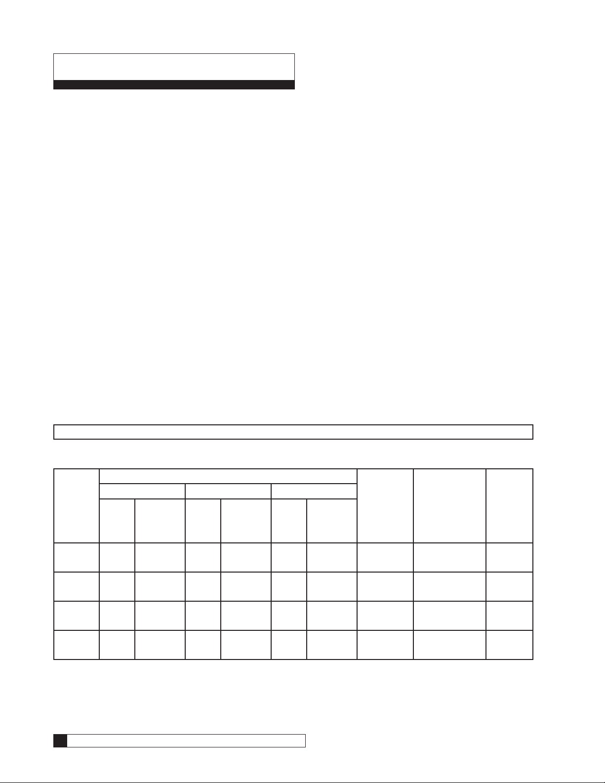
Table 1. Specifications Table for Activated Carbon Commercial Water Filters
Model Water Quality Backwash
Superior High Utility
Flow
Rate
(gpm)
CSM-242R 13 2 19 3 26 5 30
CSM-302R 20 3 30 4 40 6 46
CSM-362R 29 2 42 4 57 7 69
CSM-422R 39 3 58 6 77 9 95
Pressure
Loss
(psi)
Flow
Rate
(gpm)
Pressure
Loss
(psi)
Flow
Rate
(gpm)
Pressure
Loss
(psi)
Flow
Rate
(gpm)
Media Tank
Size & Floor
Space
Required
LxWxH
(inches)
24 x 54
25x33x74
30 x 60
31x40x90
36 x 60
37x46x90
42 x 60
43x53x92
Face
Piping
Size
(inches)
2
2
2
2
2 Culligan® CSM Series Filters
2 Cat. No. 01016449

Table 2. Specifications Table for Depth Commercial Water Filters
Model Water Quality Backwash
Superior High Utility
Flow
Rate
(gpm)
CSM-202D 22 3 33 5 44 8 30 20 x 54
CSM-242D 32 4 48 8 63 13 46 24 x 54
CSM-302D 50 6 74 13 99 20 76 30 x 60
CSM-362D 71 9 107 17 142 27 105 36 x 60
CSM-422D 97 11 145 22 193 33 150 42 x 60
CSM-423D 97 6 145 11 193 16 150 42 x 60
Pressure
Loss
(psi)
Flow
Rate
(gpm)
Pressure
Loss
(psi)
Flow
Rate
(gpm)
Pressure
Loss
(psi)
Flow
Rate
(gpm)
Media Tank
Size & Floor
Space
Required
LxWxH
(inches)
21x29x72
25x33x74
31x40x90
37x46x90
43x53x92
43x54x92
Face
Piping
Size
(inches)
2
2
2
2
2
3
Cat. No. 01016449
Performance Specifications 3

Basic Principles
Activated Carbon Filter
“Carbocleer” filters reduce unpleasant taste and odors from the water supply. In normal operation, the water passes
through the multi-port valve into the top of the media tank. As it flows down through the mineral bed, sediment in the water is filtered out and objectionable dissolved gases are absorbed into the mineral. The clear water that leaves the bottom
of the media tank and goes into the service lines is free from many disagreeable tastes and odors.
To keep the filter operating properly, it is necessary to periodically remove the accumulated sediment from the mineral
bed. This is done by a three step cleaning process:
Backwash
The direction of flow through the tank is reversed and the mineral bed is “backwashed”. This action expands and agitates
the bed, releasing the sediment which is then carried up and out to the drain.
Settle
The media tank is allowed to set idle to allow the Activated Carbon to settle. Water flow to drain will be present during the
duration of this step.
Fast Rinse
A fast down flow “flush” repacks the mineral bed and washes out traces of sediment not removed by backwash.
Generally, backwashing once a week is adequate, however, more frequent cleaning is recommended for waters with high
turbidity. Filters operated semi-automatically or automatically should be backwashed when the pressure drop across the
bed is 8 to 10 psi higher than a normal clean filter bed.
Depth Filter
Depth filters filter both heavy sediment and suspended matter from the water supply. In normal operation, the water
passes through the multi-port valve and into the top of the media tank. As the water flows down through the mineral bed,
sediment in the water is filtered out, The clear water that leaves the bottom of the media tank and goes through the service lines is free from most sediment and suspended matter.
To keep the filter operating properly, it is necessary to periodically remove the accumulated sediment from the mineral
bed. This is done by a three step cleaning process:
Backwash
The direction of flow through the bed is reversed and the mineral bed is “backwashed”. This action expands and agitates
the bed, releasing the sediment which is then carried up and out to the drain.
Settle
The tank is allowed to set idle to allow the different types of media to restratify and settle. Water flow to drain will be present during the duration of this step.
Fast Rinse
A fast down flow “flush” repacks the mineral bed and the filter is again ready for service.
It is recommended that this cleaning process take place at least once a week. On units with pressure gauges, the differential pressure across the filter can be monitored. A depth filter should be cleaned when the differential pressure across
the filter increases by 8-10 psi over the pressure differential across a clean filter bed.
4 Culligan® CSM Series Filters
4 Cat. No. 01016449
Flow Diagram
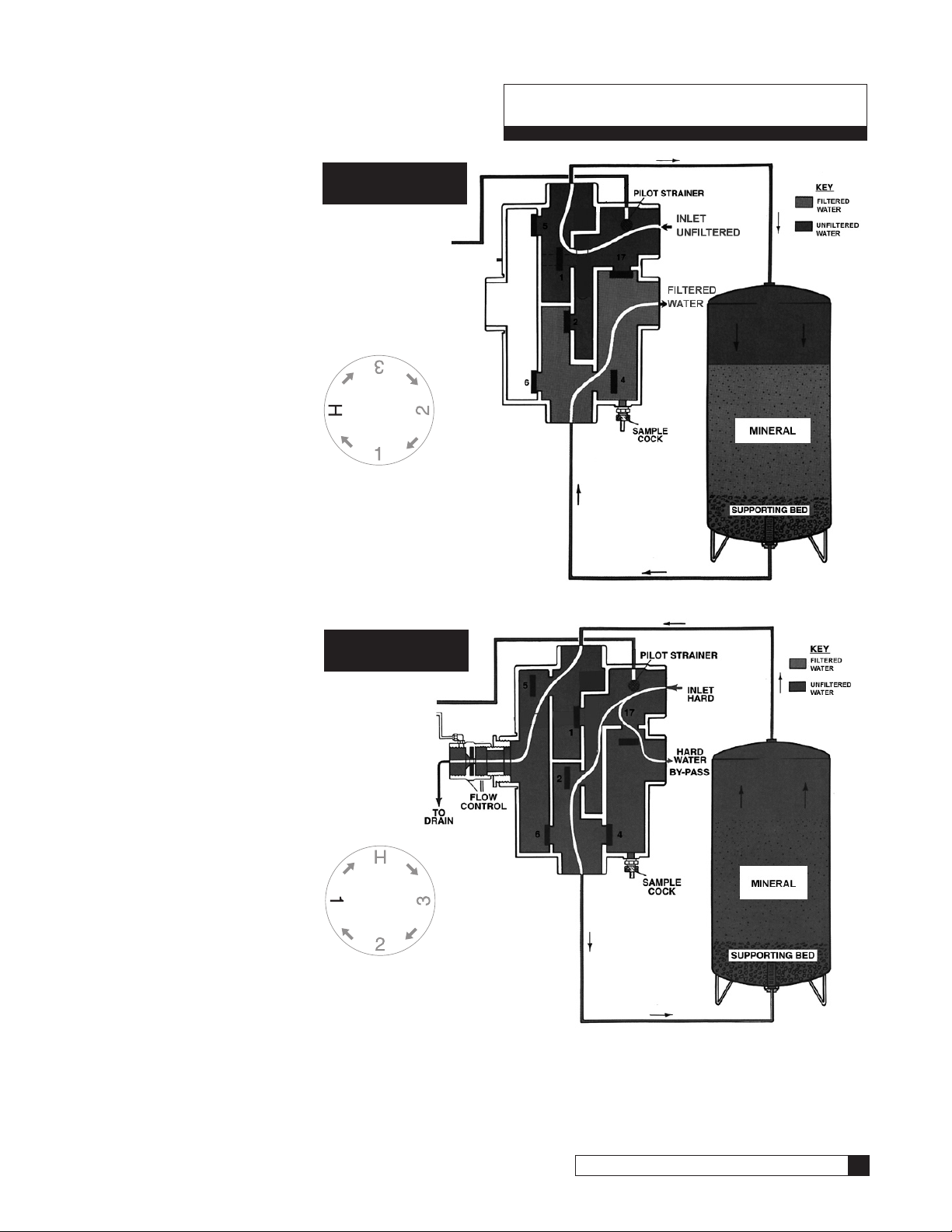
Flow Diagram -
Service Step
(H Position)
1. These diagrams illustrate the simplicity of
the Brunermatic valve
and positive control of
flow direction.
2. Note that only diaphragm valves 1 & 4
are open and flow is
directed to the top of
media tank, through
media bed, out bottom
of tank into service
line.
3. Pressure is directed
to pilot valve which
distributes pressure to
other valves.
Flow DiagramBackwash Step
(Position 1)
1. Expands and cleans the
resin bed.
2. Pilot valve changes
ports to direct water
into bottom of resin bed
and out the top of tank.
Diaphragm valves 2, 5,
and 17* are open.
3. Flow to drain is controlled by automatic
backwash flow control
assembly.
The backwash flow control assembly is accurate
over a range of 30-100
psi and insures against
media loss.
*Single tank systems requiring
bypass of unfiltered water.
SERVICE
Position
Dial
Figure 1.
BACKWASH
Position
Dial
Figure 2.
Cat. No. 01016449
Flow Diagram 5
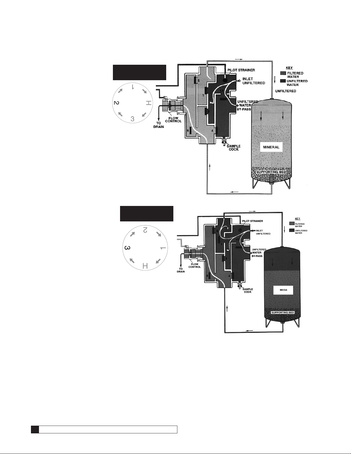
Flow Diagram -
Settle Step
(Position 2)
1. Diaphragm valve #6
opens.
2. Note that only two valves
are open in this cycle
(No. 6 and No. 17*).
3. Pressure directed through
pilot valve holds other
valves closed.
*Single tank systems requiring
bypass of unfiltered water.
Flow Diagram -
Flush Step
(Position 3)
1. Diaphragm valve # 6 opens.
2. Note that only two valves
are open in this cycle (No. 6
and No. 17*).
3. Pressure directed through
pilot valve holds other
valves closed.
SETTLE
Position
Dial
Figure 3.
FLUSH
Position
Dial
*Single tank systems requiring bypass of unfiltered water.
6 Culligan® CSM Series Filters
Figure 4.
6 Cat. No. 01016449
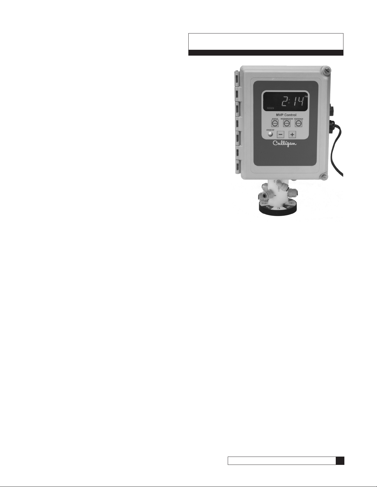
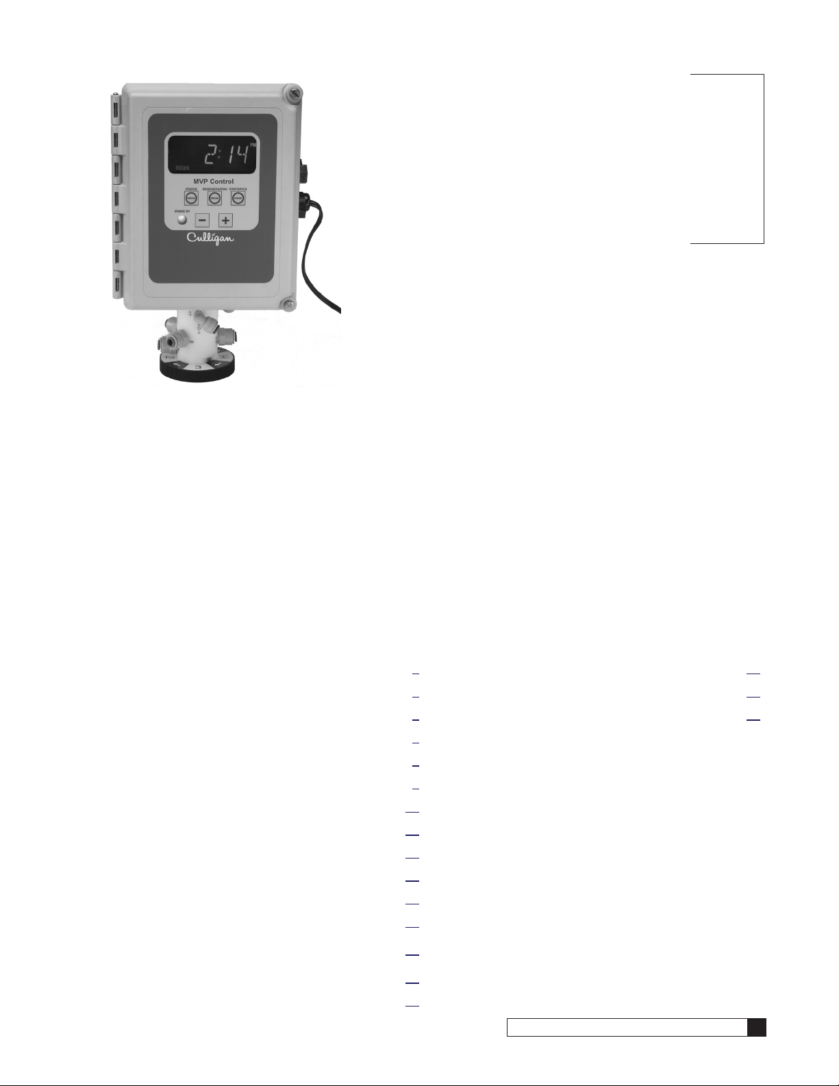
The Culligan MVP control’s (Figure 5) primary function is to initiate and
control the regeneration process via methods that are most convenient and
cost effective for the customer while offering many operation features and
benefits.
Features
Power Source
Electrical power required for the control is 24-Volt 50/60 Hz AC current. A
plug-in transformer (120v/24v) is provided
Battery Backup
Battery backup is available as an optional field add-on. The battery backup
will maintain the time of day for a minimum of 4 weeks using a 3.6V 1/2AAlithium type battery as supplied by Culligan.
EEPROM
Saves programmed and statistical functions.
AC Outputs
Four AC outputs are found within the controller for the following purposes:
• Motor control
• Blocking Valve (blocks the flow of water to service)
• Two programmable outputs for various optional accessories
Controller Features
Figure 5.
One-Touch Program Update
Multiple controls can have their programs updated simply through the touch of a button on the primary or “Master” control
eliminating the need to the programming process for each subsequent control in a system.
Lock/Unlock
Allows the control to be easily locked out from inadvertent program changes or abuse. This feature can be disabled if
desired.
Time of Day
Displays current time in either 12 hour (AM/PM) or 24 hour format.
Current Day of Week Regeneration
This feature is available for single, time clock operated systems.
Regeneration Interval
Provides an ability to initiate a time clock operated system on a number of days (range from 1 to 99 days), hours (range 1
to 24 hours), or a specific day of the week (single, time clock systems).
Progressive Flow Trip Point
Use of this patented feature allows multiple tank systems operating with water meters to be brought on-line or off-line as
facility flow demands increase or decrease.
Regeneration Start Delay
Allows a user determined number of hours (up to 9) to be input into the control for the purpose of increasing the amount
of time between multiple regeneration initiations.
Cat. No. 01016449
Controller Features 7

Program Beeper
Emits an audible beep when key pads are depressed to help identify valid (short beep) or invalid (3 short beeps) key pad
touches. Can be enabled or disabled as desired.
Screen Blanking
The screen can be programmed to go blank once programming is complete (After 5 minutes of no keypad activity).
Flow Meter/Sensor Input
Various types of Hall effect flow sensors can be used to measure the amount of treated water provided and initiate a
regeneration sequence.
Auxiliary Input
The auxiliary input is capable of accepting a remote signal from a dry contact device such as an operator push-button for
the purpose of initiating the regeneration sequence.
Home and Position Switch Inputs
The home and position switch inputs work to automatically detect the cycle position of the valve and properly configure
the circuit board for operation with either a four or five-cycle valve. The inputs also assist the operator to troubleshoot
many types of service problems.
Multiple Unit Communication Input/Output (RS485)
The communication input/output feature routinely recognizes when another controller within a multiple controller system is
in a regeneration sequence, prohibiting the chance of multiple units regenerating simultaneously. Additionally, the Communication input/output feature provides the means to operate the controller in the Progressive Flow mode.
8 Culligan® CSM Series Filters
8 Cat. No. 01016449

Operation
Modes of Operation
Time Clock
The controller will initiate a regeneration based upon a time schedule of either hours (between 1 to 24 hours), intervals of
days (i.e., every 3 days) or on a specific day of week schedule (i.e., Mondays, Wednesdays and Saturdays).
Differential Pressure
When combined with an optional differential pressure device, the Culligan MVP controller has the ability to initiate a backwashing sequence when the pressure differential across the media bed reaches a preset amount (usually 8 to 10 psi).
Progressive Flow
Used with up to six and as few as two mineral tanks in a system, the Progressive Flow mode allows more than one tank
in a system to either be on-line or off-line depending upon the downstream flow demand. If flow demand is greater than
the flow capability of the tank on-line, another tank can be brought on-line to help satisfy the excess demand. Once the
demand has decreased, the second tank is returned to a standby mode and the system reverts to just one tank on-line
providing treated water.
The progressive flow mode of operation relies on a user programmable set point or Trip Point. The Trip Point is a unit of
flow (gallons or liters) on a per minute basis. Once attained the trip point will cause the second unit (in multiple resin tank
system) to come on-line. Each additional resin tank in the system will subsequently be brought on-line as multiples of the
trip point are attained. (Example: a 3 tank system with a trip point of 50 gpm will bring have two tanks on-line once the
facility flow demands is equal to or greater than the 50 gpm trip point. Should the flow demand reach 100 gpm or more,
the third tank shall be brought on-line.
Additional tanks shall be returned to stand-by once the facility flow demand is <95% of the trip point for two tank systems,
<95% of 2X the trip point for triplex systems and <95% of 3X the trip point for quad systems, and remains there for 60
seconds.
Utilizing the progressive flow feature may allow the owner to use smaller water softening models, resulting in the potential
for reduced capital and operation costs.
The Progressive Flow setting may be used in combination with differential pressure device.
Cat. No. 01016449
Operation 9
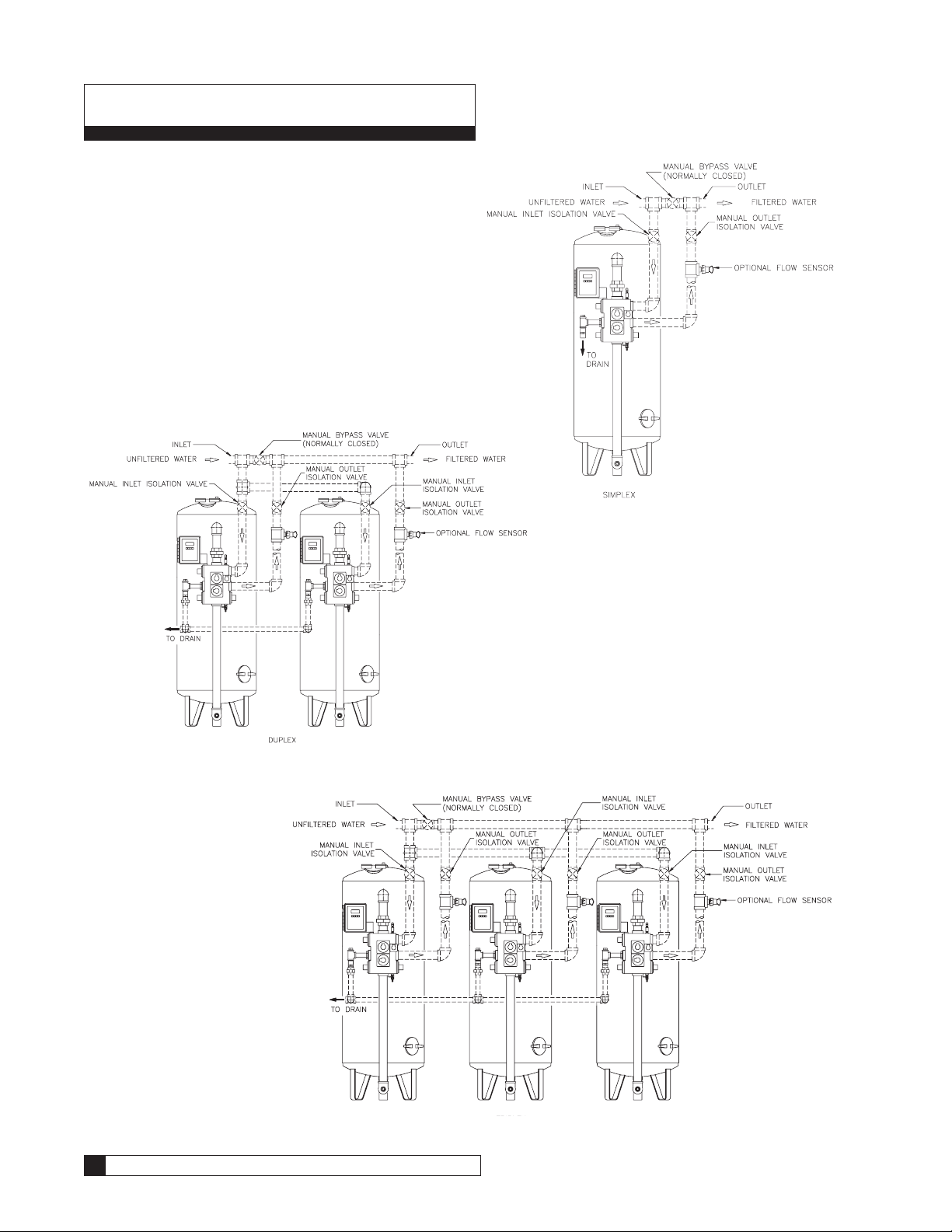
Installation
Figure 6.
Figure 7.
10 Culligan® CSM Series Filters
Figure 8.
10 Cat. No. 01016449
Make certain to follow each step carefully to insure that the filter runs trouble free. Also, be sure all plumbing practices
conform to local plumbing codes.
Locate Filter
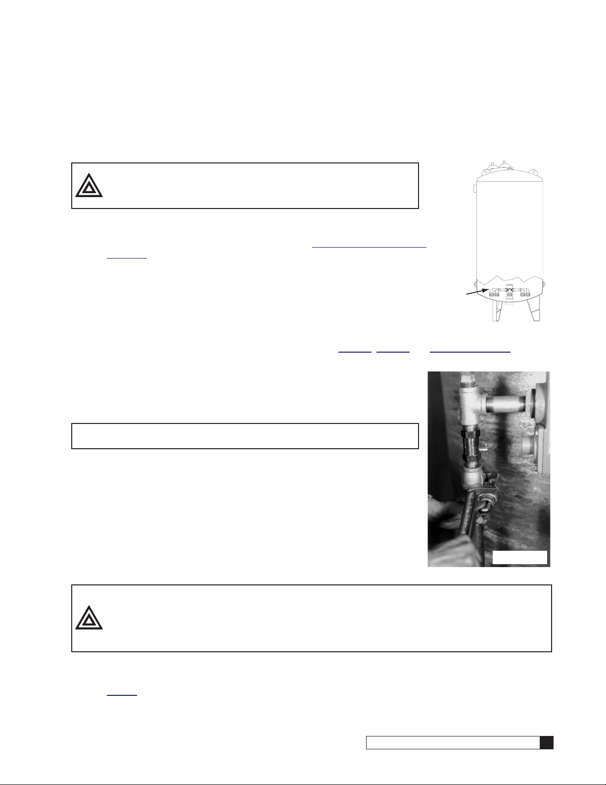
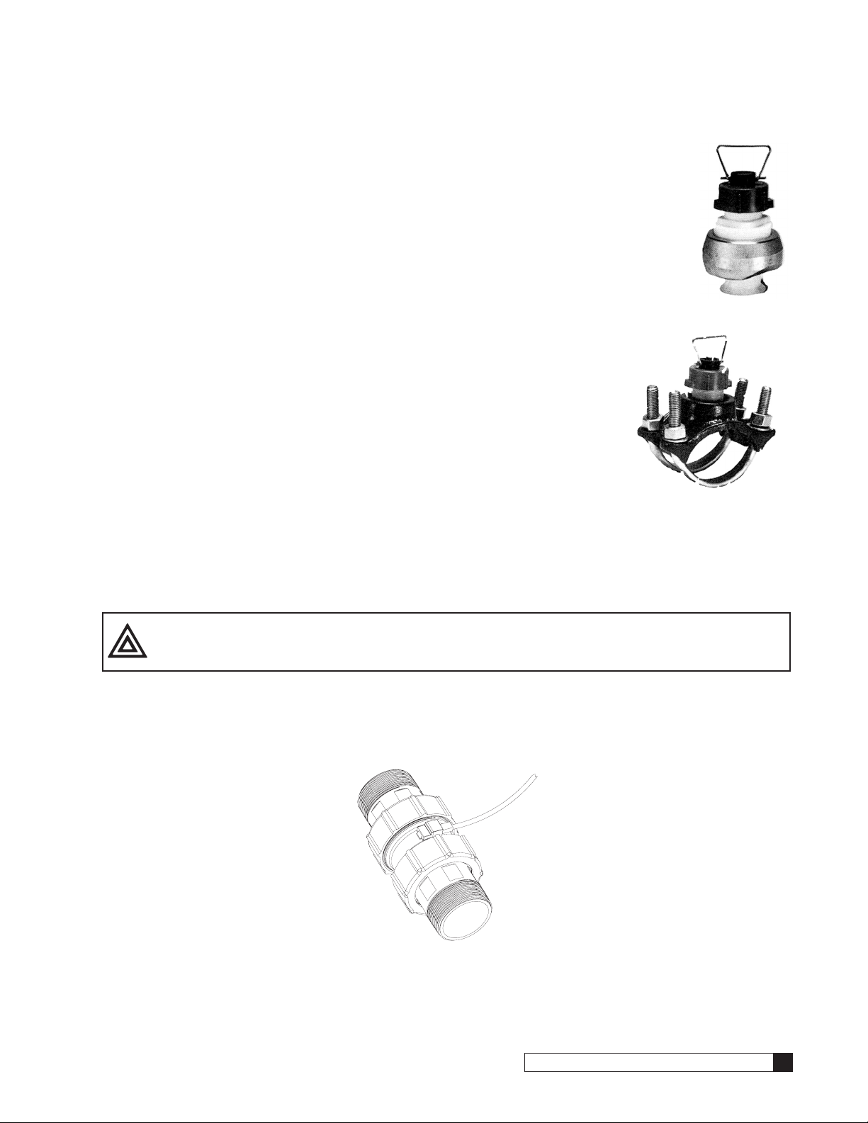
1. Check inside the tank to make sure that all of the plastic distributors and laterals (Figure 9) are tight.
CAUTION! Do Not Proceed if any distributors or laterals are broken.
Consult Culligan for assistance. If any are loose, hand
tighten only. Do not use a wrench.
2. If the tank drain valve option kit was purchased, install it at this time.
3. Select a position near a floor drain that has adequate carrying capacity to han-
dle the filter’s backwash flow rate. Refer to section, “Performance Specifications”
on page 2 for specific backwash flow rate.
4. Erect the resin tank on a level firm foundation, preferably concrete. The valve
and piping normally face the front for easy access.
5. Level the system.
Figure 9.
DISTRIBUTORS
AND LATERALS
Install Piping
1. Depending on the type of filter system (i.e. single, twin, etc.) and installation parameters, required pipe lengths
and piping accessories will vary. Sample layout drawings (Figure 6, Figure 7 and Figure 8 on page 10) are
provided to aid the installation. If the layout drawings are not sufficient for your application, consult the equipment provider for specific installation guidelines.
The use of unions on the inlet and outlet isolation valves is recommended to
facilitate service of the softener unit. It is recommended that a full flow by-pass
line be provided.
NOTE All pipe fittings and assemblies should follow good plumbing practices
for installation.
They are:
• Check the threads and make certain that they are clean and free of foreign
matter.
• Fittings must be free of cracks or chips.
• Prepare threads with either a pipe dope sealant or Teflon tape.
• Make certain that the fittings are not cross threaded during the assembly
process.
• Do not over-tighten fitting or threaded pipe being inserted into a cast or
forged part.
CAUTION! Never connect two dissimilar metals (such as copper pipe and aluminum valves) togeth-
er when plumbing the vale to the piping system. The use of unions (dielectric unions
if piping to cast iron valves) on copper or galvanized steel pipe followed by schedule
80PVC or CPVC short nipples to attach the piping to the control valve is strongly recommended to reduce the potential of corrosion by galvanic reaction.
2. Pipe a drain line from the backwash flow control assembly (left side of the Brunermatic valve) to the drain. Use
a minimum of elbows and increase or decrease the pipe size in order to make a connection to the backwash
flow control assembly. (see Figure 10) DO NOT install a valve in this line or use pipe smaller than listed in the
Table 3:
Figure 10.
Cat. No. 01016449
Installation 11
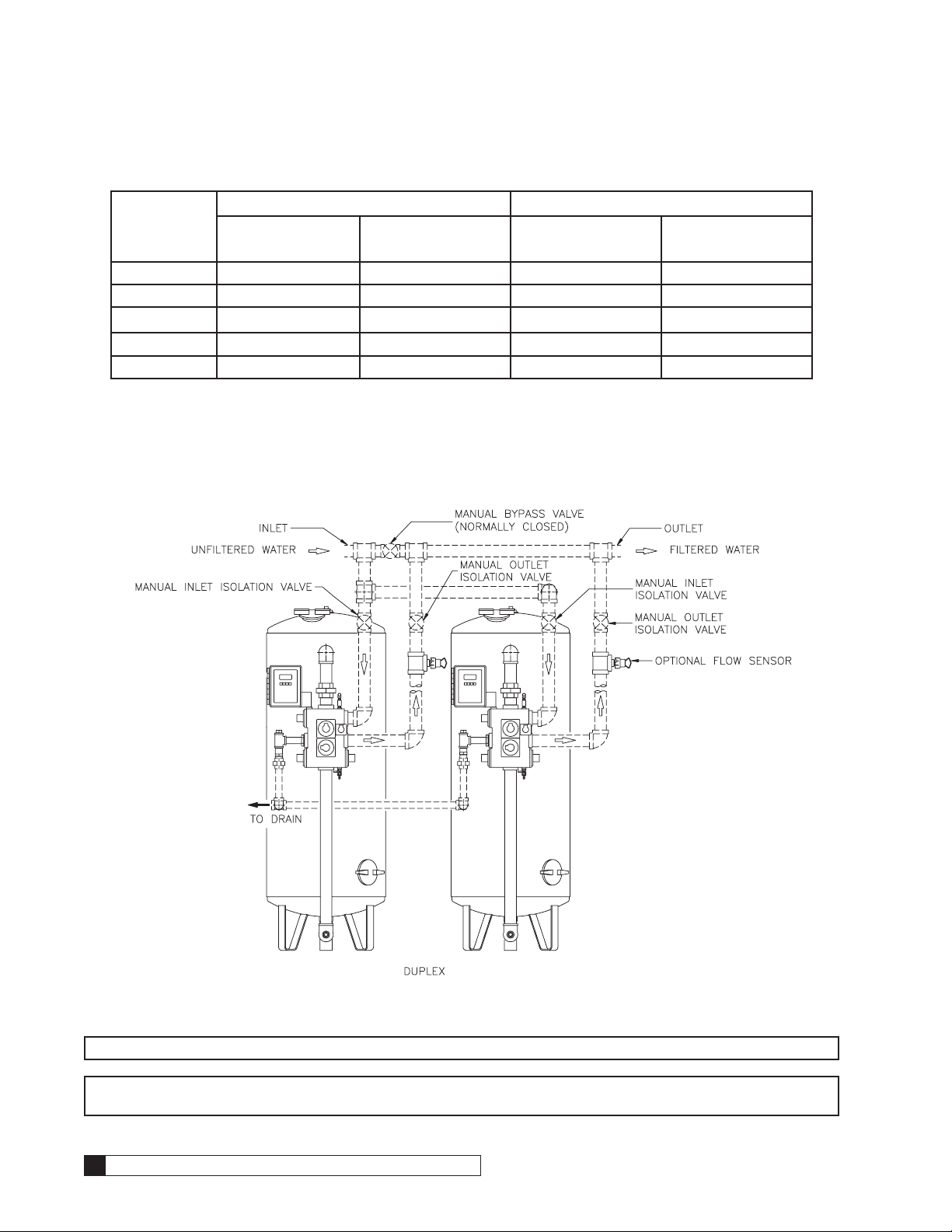
Table 3.
Carbon Filters Depth Filters
Tank Size
20 x 54 20 1-1/4 30 1-1/4
24 x 54 30 1-1/4 46 2
30 x 60 46 2 76 2-1/2
36 x 60 69 2 105 3
42 x 60 95 2-1/2 150 3
3. Install a union near the backwash flow control assembly to facilitate service when required.
DO NOT make a direct connection to the drain. Provide an air gap of at least four times the diameter of the drain
pipe or conform to local sanitation codes and to permit the observation of the drain flow.
Backwash Rate
(gpm)
Drain Line Size
(in.)
Backwash Rate
(gpm)
Installation of the Flow Measuring Device (Option)
Drain Line Size
(in.)
Figure 11.
NOTE *interconnecting piping, bypass valve and isolation valves are not supplied.
NOTE Time or initiated regenerated systems do not necessarily require the use of a flow-measuring device.
Therefore your system may not utilize this portion of the manual.
12 Culligan® CSM Series Filters
12 Cat. No. 01016449
Two popular types of flow measuring devices can be used with the controller; paddlewheel flow sensors or the Culligan
Valve Prior to Flow Sensor
in-line turbine meter. Please refer to the following chart for the number of meters required for your system configuration.
Table 4.
System Configuration Paddlewheel Flow Sensor Turbine Meter
Single 1 1
Duplex Parallel/Progressive Flow 2 2
Duplex Alternating 1 1
Triplex Parallel/Progressive Flow 3 3
To properly measure flow accurately, the paddlewheel flow sensor(s) must be installed with a certain amount of straight
pipe both before and after the paddlewheel flow sensor. The proper installation for these types of systems is shown on
below and page 14. Turbine meters do not have the same installation requirements and therefore may be positioned
immediately following the Brunermatic valve if the system is a single or parallel configuration or at any point in the common outlet header for alternating configurations.
Location of the Paddlewheel Flow Sensor Package
The flow sensor is to be mounted on the outlet piping of each
filter for single and duplex and triplex parallel systems and in the
common outlet piping of duplex alternating systems.
The piping that the flow sensor is being connected to should
be the same diameter as the mounting fitting. The flow sensor
must also be located in a free-flowing straight run of pipe. This
straight run includes the upstream piping and downstream piping of the flow sensor.
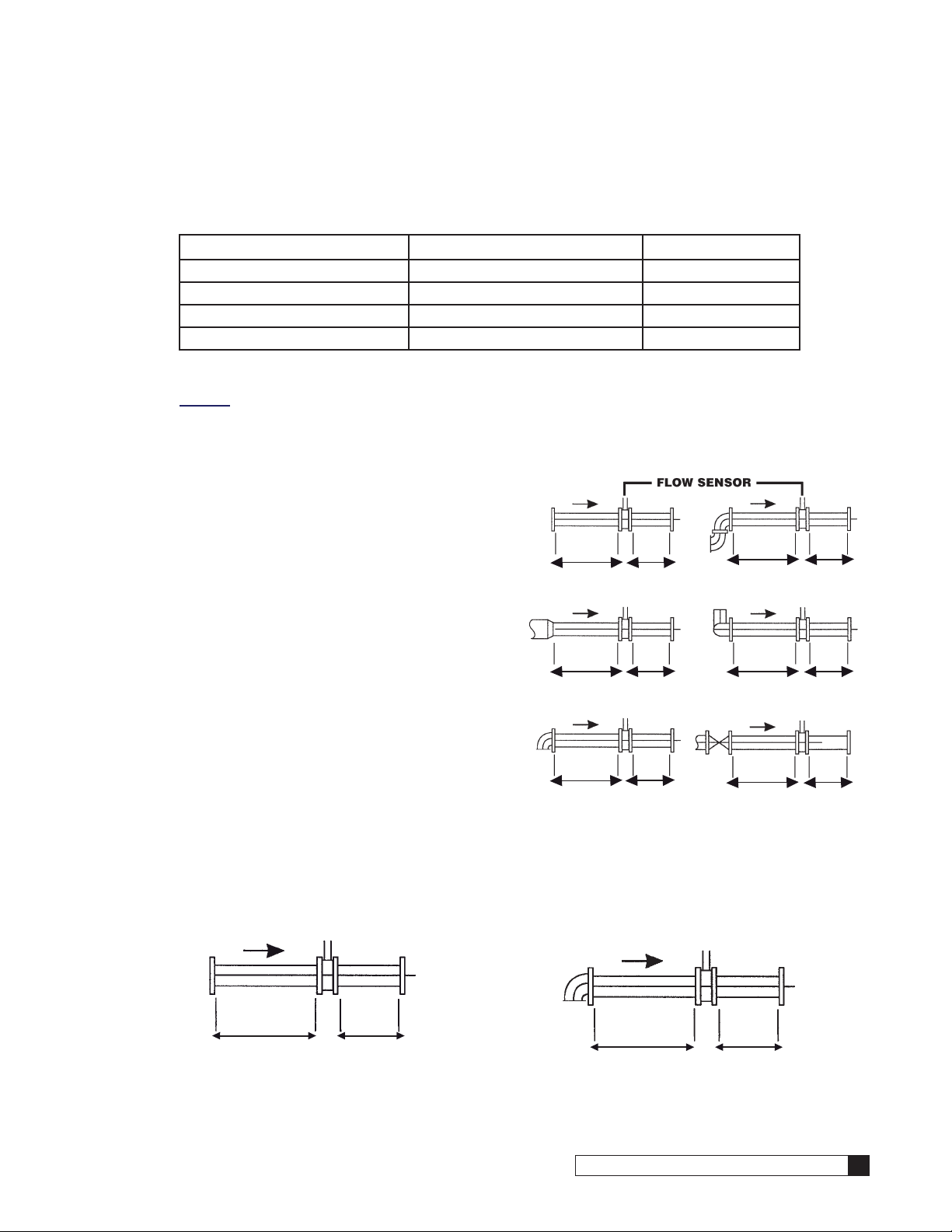
The proper length of upstream and downstream straight piping
is a minimum of 10 pipe diameters of free-flowing straight pipe
upstream of the flow sensor and 5 pipe diameters of free-flowing
straight pipe downstream.
EXAMPLE: A flow sensor that is installed on a length of 2” diameter straight pipe (see Figure 13).
Major obstructions will require considerably longer straight runs
of upstream piping, due to the turbulence created by their presence.
EXAMPLE: A flow sensor on a length of 2” diameter pipe that
has a 90° elbow upstream from the desired location (see Figure 14).
The examples below are intended as guide lines for the proper length of straight pipe required both upstream and downstream of the flow sensor installation point.
These recommendations are minimum requirements (see Figure 12).
10 x D5 x D
Straight Pipe Two Elbows in Same Plane
15 x D 40 x D
Reducer Prior to Flow Sensor Two Elbows in Different Planes
20 x D
Single Elbow Prior to Flow Sensor
5 x D
Figure 12.
25 x D
50 x D
5 x D
5 x D
5 x D5 x D
Figure 13. Example: D = 2”
Cat. No. 01016449
10 x D = 20”
5 x D
= 10”
5 x D
20 X D = 40”
Figure 14. Example: D = 2”
= 10”
Installation 13
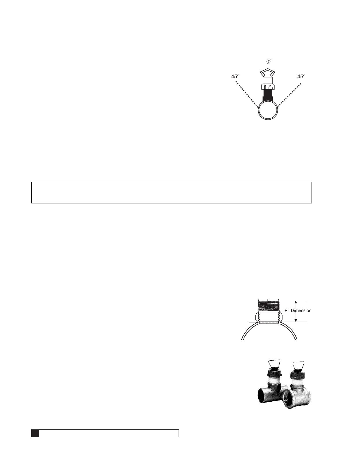
Position of the Flow Sensor Package
The flow sensor position is also important to the accuracy of the output signal. When
installing the flow sensor in a horizontal pipe, the optimum position of the flow sensor
in the pipe is at 0 or 180 degrees, assuming the pipe is always full of liquid and contains no suspended solids. Air pockets or sediment in the pipe will disturb the rotation
of the flow sensor, causing inaccuracy in the output signal.
Because of certain installation requirements due to space restrictions, it may be necessary to tilt the flow sensor slightly, (max. 45° angle). Excessive angles will cause
bearing drag on the flow sensor rotor at lower flow rates (see Figure 15).
On a vertical pipe run, it is preferable to locate the flow sensor where the flow is
upward. But, if downward flow is necessary, the system must be designed to prevent
air/water vapor pockets from developing in the pipe which will affect the performance of the flow sensor.
The maximum distance that the flow sensor can be located from the MVP controller is 500’. Paddlewheel type flow sensors should be supported in the piping as required by local plumbing codes; typically 18” before and after each joint (in a
horizontal run of pipe).
Figure 15.
Signet Flow Sensor Installation
NOTE Signet flow sensors must be installed as indicated. Failure to follow these instructions may result in
improper operation. Please refer to any supplemental instructions accompanying the flow sensor for
additional information.
1. Once you have located the flow sensor package and confirmed it is the correct size and material type for the
equipment at the site, proceed with installing the flow sensor mounting package.
2. You should follow good plumbing practices for all the installations. They are:
• Check the threads and make certain that they are clean and free of foreign matter.
• Fittings must be free of cracks and chips.
• Prepare threads with either a pipe sealant or Teflon tape.
• Make certain that the fittings are not cross threaded during the assembly process.
• Do not over-tighten the fittings or the threaded pipe that is being threaded into a casting or forging.
• Follow proper soldering processes as outlined in the plumbing code.
3. For each of the different types of installations, certain requirements must be followed to assure a proper installation.
a. Copper sweat tee - for use on copper tubing sizes. 1” 1-1/4”, 1-1/2”
and 2”. With the exception of the 1” copper sweat tee, all of the copper tees include a plastic insert which the flow sensor will attach to.
This insert should be removed in order to properly solder the tee into
the correct position. A tag is attached to the fitting to indicate the proper “H” dimension of the plastic insert when reassembling. This dimension is critical to the proper calibration of the flow sensor. Note the
location of the notch to the pipe (see Figure 16).
b. Threaded galvanized tee - for use on galvanized/iron pipe sizes 1”, 1-1/4”,
1-1/2” and 2”. All tees are threaded with NPT threads and have a plastic
insert to attach flow sensor. This insert is factory installed and should not
be removed. It is necessary for determining the proper location for the flow
sensor wheel when inserted into the fitting. Again this insert should not be
removed from the tee assembly (see Figure 17).
Figure 16.
14 Culligan® CSM Series Filters
Figure 17.
14 Cat. No. 01016449
c. Copper brazolet - for use on copper pipe sizes 2-1/2” and 3”. The copper brazolet
should be installed by a certified welder. A hole will need to be drilled in the pipe at
the desired location as described in this section. The hole size should be 1-7/16” and
must be completely deburred and free of any projections. Prior to welding the brazolet, the plastic insert must be removed. A special tool is provided with each brazolet
assembly for the removal and the replacement of the plastic insert. When the plastic
insert is replaced (after the welding is complete), Teflon tape should be used on the
threads. There is a special card that is attached to the insert, this card indicates the
proper “H” dimension for the insert depth when you reassemble the insert back into
the brazolet. This dimension is critical to the proper calibration of the flow sensor.
Note the location of the notch to the pipe (see Figure 18).
d. Iron saddle - for use on steel pipe 2”, 2-1/2” and 3”. A 1-7/16” hole will
need to be drilled in the pipe at the desired location as described in this
section. The assembly comes complete with a plastic insert which is factory installed and should not be removed. The assembly also comes with
a rubber washer which must be installed between the clamp and pipe.
Coat the rubber washer with a silicon lubricant and place it on the inside
of the saddle and form it around the raised groove. With the flat side of
the rubber washer facing the pipe surface, insert the plastic insert and
saddle to the drilled hole. Using the saddle clamps, tighten the saddle
into place.
e. PVC socket weld tee - for use on sizes 1”, 1-1/4”, 1-1/2”, 2”, 2-1/2”, 3”
and 4” schedule 80 PVC pipe. All tees are socket welded with a NPT
threaded port containing a plastic insert to attach the flow sensor. This insert is factory installed and
should not be removed. It is necessary in determining the proper location for the flow sensor wheel
when inserted into the fitting. Again, this insert should not be removed from the tee assembly. Once
the flow sensor installation is completed, locate the warning decal attached to the flow sensor. Apply
the decal to a visible location near the flow sensor in the event service is required.
Figure 19.
Figure 18.
CAUTION! Be certain there is no pressure in pipe BEFORE removing or installing flow sensor.
Turbine Meter Installation
Turbine meters are less sensitive to position. They can be mounted horizontally or vertically but straight runs before and
after the meter are best for accuracy. If mounted vertically, the water flow must be upward. Turbine meters however must
be supported as required by local plumbing codes; typically 18” before and after each joint (in a horizontal run of pipe).
Figure 20.
Cat. No. 01016449
Installation 15
Loading the Media Tank
Installing the Gravel Support Bed
1. Verify that the correct type and amount of gravel for the system is on site. The proper amount of gravel is
indicated in the following table. If the correct type and amount of gravel is not on site, DO NOT load the tank.
Contact the equipment provider for assistance.
Table 5.
Underbedding, lbs.
Non-Code Tanks
Part Number (Qty)
Size
Size
Layer 1
Med.
Gravel
Layer 1
Med.
Gravel
Layer 2
Cullsan U
Layer 2
Cullsan U
Carbon
Tank
Filters
CSM-242R 24 x 54 100 100 125 100 220 18.00 19.00
CSM-302R 30 x 60 150 150 200 150 330 26.25 26.50
CSM-362R 36 x 60 250 250 350 250 495 24.50 25.00
CSM-422R 42 x 60 350 350 550 350 660 25.50 25.00
Depth
Tank
Filters
CSM-202D 20 x 54 100 50 100 50 100 100 165 150 17.50 19.00
CSM-242D 24x 54 100 100 150 100 150 250 220 250 16.50 16.25
CSM-302D 30 x 60 200 150 250 150 200 200 330 350 25.00 25.50
CSM-362D 36 x 60 300 200 450 200 250 250 495 500 26.00 25.50
CSM-422D
CSM-423D
42 x 60 450 300 700 300 350 350 660 700 19.00 24.50
Underbedding, lbs.
ASME-Code Tanks
Part Number (Qty)
Layer 1
Med.
Gravel
Layer 1
Med.
Layer 2
Cullsan U
Layer 2
Cullsan U
Gravel
Filter Media, lbs.
Part Number (Qty)
Layer 3
Cullar D+
Layer 3
Cullsan G50
NonCode
ASME
Code
Layer 4
Cullsan A
Layer 5
Cullcite
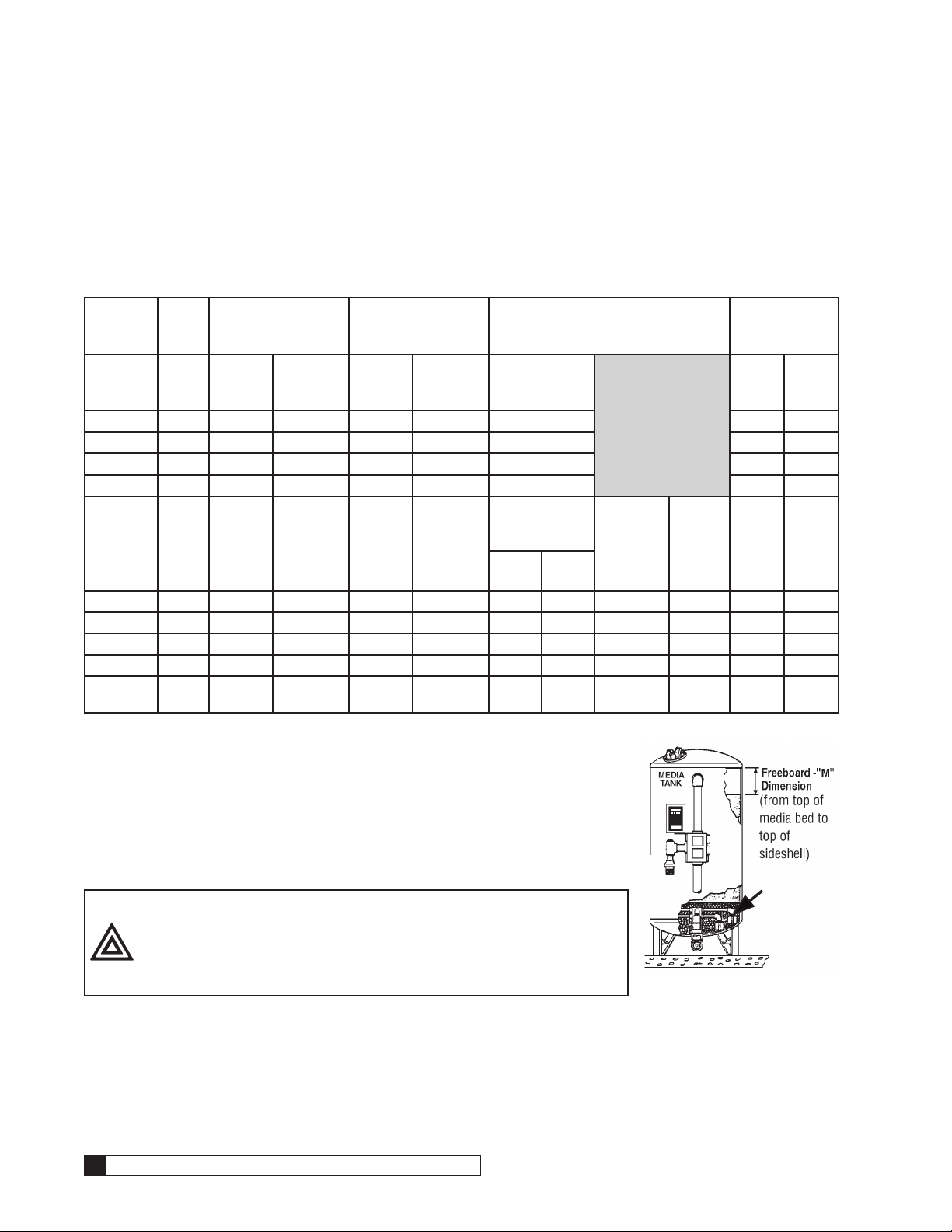
Freeboard
Dimension
“M” (in.)
Non
ASME
Code
Non
ASME
Code
Code
Code
2. Make sure all manual valves are closed. To prevent damage to the distribution system, add approximately 2 feet of water to the media tank with a hose
(Figure 21). It is not recommended that the media tank be entered to receive
and load the gravel. With water in the media tank, carefully pour the gravel
slowly into the media tank, leveling as loading progresses. On media tanks
with only a handhole in the top, it is recommended that a funnel be used to
load the gravel into the media tank to help prevent spillage. When properly
loaded, the gravel should cover the distributor system in the bottom of the
tank. If it does not, contact your Culligan dealer before proceeding to Step 3.
Distributor
System
CAUTION! Should it be necessary to enter the media tank, it is
recommended that a respirator be worn by any person
entering the tank to load gravel. Wet the bags of gravel
to reduce the amount of dust caused by the loading
procedure.
Figure 21.
16 Culligan® CSM Series Filters
16 Cat. No. 01016449

3. Level the Gravel Support Bed. An easy way to determine the levelness of the gravel support bed is to add water
(Figure 22) to the surface of the gravel. It may be necessary to add or remove
water to insure that the water level is at or near the same height of the gravel
level. Make certain that no foreign materials are left in the tank. This includes the
bags that the gravel is shipped in.
Installing Activated Carbon Filter Media
1. Before adding the Activated Carbon, verify that the correct type and amount of
Activated Carbon for the filter you are installing is on site. If the correct type and
amount (Table 5) of Activated Carbon is not on site, contact the Culligan Dealer
that sold you the filter.
2. Slowly pour in the Activated Carbon. It is recommended that a funnel be used on
those units with spin top and handhole covers, when loading Activated Carbon into the media tank. Make certain that no foreign material is left in the media tank.
3. With the MVP controller unpowered, rotate the position dial to the Backwash (#1) position. Slowly open the inlet
isolation valve and allow the media tank to slowly fill up with water until the water level covers the mineral bed.
The freeboard dimension should be checked at this time. If the freeboard dimension is correct, rotate the position dial to the Home (H) position at this time.
4. Do not install the spin top, handhole or manhole cover(s) at this time. Allow 24 hours for the air to escape from
the media tank.
Figure 22.
Installing Depth Filter Media
1. Before loading the different types of media, verify that the correct type and amount (Table 5) of each media for
the filter you are installing is on site. If the correct type and amount of each media is not on site, contact the
Culligan Dealer that sold you the filter. The media must be loaded into the mineral tank in the proper order to
assure proper filter operation. It is recommended that a funnel be used on those units with spin top and handhole covers, when loading each layer of media into the media tank.
2. Layer 2 - Slowly pour in the 8-12 mesh garnet. Make certain that no foreign material is left in the media tank.
Carefully level this layer of media. With the MVP controller unpowered, rotate the position dial to the Backwash
(#1) position. Slowly open the inlet isolation valve and allow the media tank to slowly fill up with water until the
water level is just at the top of this layer of media. Close the inlet isolation valve and verify that this layer of
media is level.
3. Layer 3 - Slowly pour in the 30-40 mesh garnet. Make certain that no foreign material is left in the media tank.
Carefully level this layer of media. Slowly open the inlet isolation valve and allow the media tank to slowly fill up
with water until the water level is just at the top of this layer of media. Close the inlet isola-tion valve and verify
that this layer of media is level.
4. Layer 4 - Slowly pour in the 0.35-0.45mm red flint sand. Make certain that no foreign material is left in the media
tank. Carefully level this layer of media. Slowly open the inlet isolation valve and allow the media tank to slowly
fill up with water until the water level is just at the top of this layer of media. Close the inlet isolation valve and
verify that this layer of media is level.
5. Layer 5 - Slowly pour in the 6-16 mesh carbon. Make certain that no foreign material is left n the media tank.
Carefully level this layer of media. Slowly open the inlet isolation valve and allow the media tank to slowly fill up
with water until the water level is just at the top of this layer of media. Close the inlet isolation valve and verify
that this layer of media is level.
6. The freeboard dimension should be checked at this time. If the freeboard dimension is correct, rotate the posi-
tion dial to the Home (H) position at this time.
7. Do not install the spin top, handhole or manhole cover(s) at this time.
Cat. No. 01016449
Installation 17
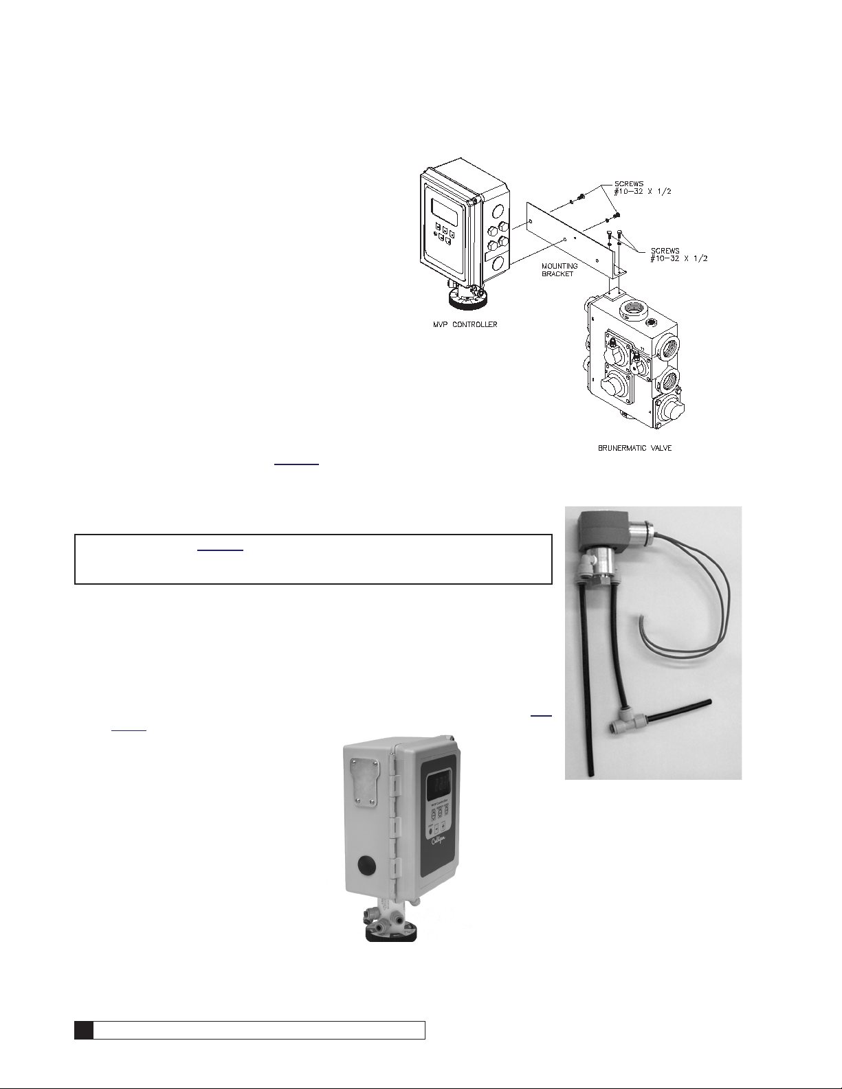
Controller Mounting
The MVP controller is shipped in its own box, complete
with transformer assembly, tubing assembly, mounting
bracket, and hardware.
1. Remove the controller mounting bracket from
the shipping carton. If the conditioning cartridge
option kit was ordered, follow the instructions
included with the kit to install the cartridge
assembly on the mounting bracket.
2. Install the controller to the mounting bracket
using the supplied hardware. Refer to Figure
23.
3. Install the bracket mounted controller to the
Brunermatic valve using the supplied hardware.
4. Retain the other items in the shipping carton for
future use.
5. If a solenoid blocking valve kit was shipped with
the system (for use in twin alternating systems),
install to the controller. Follow instruction steps
in following section and on page 28.
Figure 23.
Installation and Operation of the Blocking Solenoid Valve for Multi- Tank
Alternating Operation
NOTE Proceed to page 20 if your system is a single tank configuration.
The solenoid valve is only required for multiple unit alternating or
progressive flow systems.
The purpose of the solenoid valve (Figure 24) is to assist the controller in providing
automatic alternation of multiple tank systems. Each Brunermatic multiport valve in the
system will require its own solenoid valve. The solenoid should be mounted to the left
side of the controller (see Figure 25). These solenoids are tubed as follows:
• From solenoid valve port number 1 to Brunermatic multiport valve port number 4.
• From solenoid valve port number 2, tee into the tubing that attaches to the “IN”
port on the pilot valve body.
• From solenoid valve port number 3 to port number 4 on the pilot valve body (Fig-
ure 26).
Blocking Solenoid for
Alternating Operation
18 Culligan® CSM Series Filters
Figure 24. Solenoid
Valve Kit
Figure 25.
18 Cat. No. 01016449
6
IN
DR
1
3/4
2
5
Brunermatic
Valve
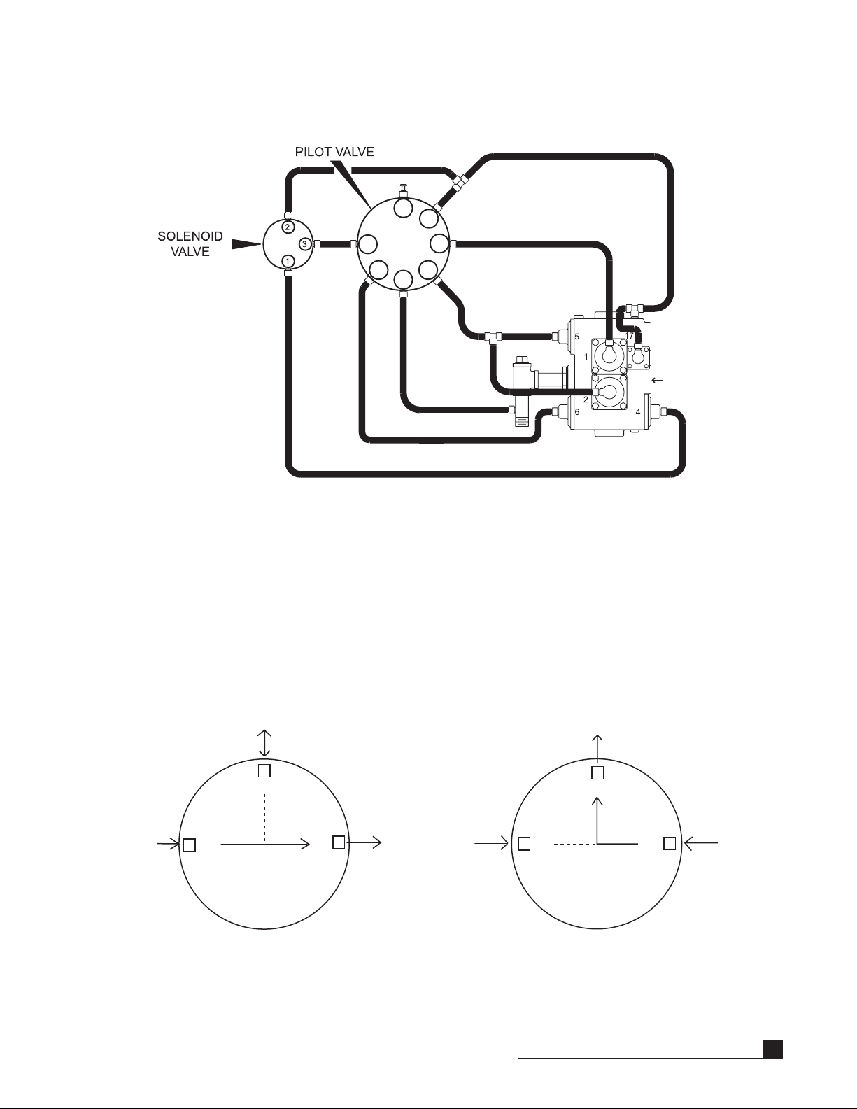
Figure 26. Alternating/Progressive Flow Parallel System w/ Plugged Bypass
Sequence of Operation
When a filter is in standby or a regeneration cycle, the MVP controller sends a signal to the P7 SOL-VIV terminal of the
primary circuit board, activating the solenoid valve. The orange LED will be on at this time. When the solenoid valve is
electrically activated, ports #1 and #2 of the solenoid (Figure 27) become common. This will direct pressure from the
constant IN pressure supply to Brunermatic diaphragm valve #4, which prohibits the flow of water through the outlet of the
Brunermatic valve.
Once the controller signals the unit to return to a Service status, the signal from P7Solvlv is removed and the solenoid
valve is deactivated. When the solenoid valve is electrically deactivated, ports #1 and #3 of the solenoid become common. The orange LED will not be on at this time. This will vent pressure, from Brunermatic diaphragm valve to port #4 on
the pilot valve body and then to drain. Brunermatic valve #4 opens which allows filtered water to flow through the outlet of
the Brunermatic valve.
From
"IN"
on
Pilot Valve
Body
(pressurized)
Cat. No. 01016449
To port #2 on Pilot Valve Body
(pressurized during regen,
no pressure in standby mode)
3
N
/
O
2
/
C
N
Solenoid Valve
Solenoid Valve Energized
When Tank
in Regen or Standby
To port #2 on Pilot Valve Body
3
N
/
O
1
/N
O
To
Port #4
(pressurized)
From
"IN"
on
Pilot Valve
Body
(pressurized)
N
2
/
C
N
/
1
O
(no pressure)
From
Port #4
on
Brunermatic
Valve
(no pressure)
Solenoid Valve
Solenoid Valve Not Energized
When Tank "Online"
Figure 27.
Installation 19
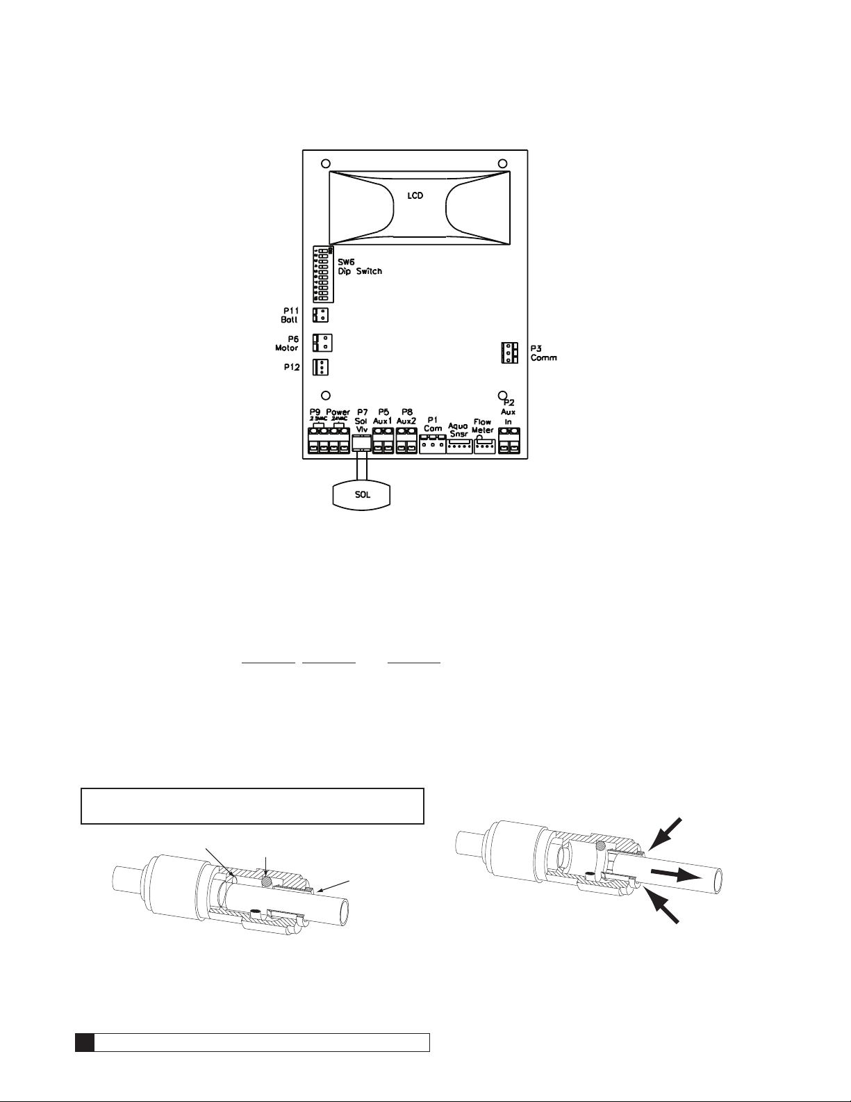
Figure 28.
Tubing Installation
The tubing assembly is shipped in the same carton as the controller. The tubing is suppled in lengths pre-cut to connect
up to a 3” Brunermatic valve.
1. Using the tubing supplied, interconnect the controller, Brunermatic valve, and any accessory kits ordered with
the system. Refer to Figure 31, Figure 32, and Figure 33 for system tubing diagrams.
2. For ease of installation, some tube fittings on the system are the push-in type. Tubing is simply inserted into the
fitting collet to make a secure, leak free connection. Refer to Figure 29 and Figure 30 for details on proper connection and disconnection.
CONNECTION
To make a connection, simply push the tubing in by hand.
NOTE The fitting will grip before it seals. Make certain
the tubing is fully pushed into the tube stop.
TUBE STOP
Figure 29.
20 Culligan® CSM Series Filters
O -RING
COLLET
DISCONNECTION
To disconnect tubing, push in the collet against the face
of the fitting. With the collet held against the face of the
fitting, the tubing can be removed.
Figure 30.
20 Cat. No. 01016449
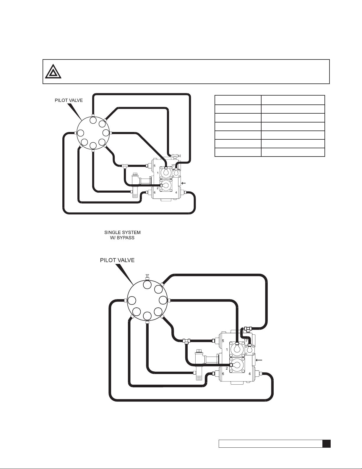
CAUTION! The port numbers on the Brunermatic valve may not coincide with the ports on the
Brunermatic
MVP pilot valve. Refer to Table 6 for cross-reference information.
Table 6. Cross Reference Port Chart
Pilot Valve Brunermatic Valve
1 1
6
IN
DR
1
3/4
Valve
2
5
3 2
2 4
4 5
5 6
6 17
Figure 31.
6
IN
DR
1
3/4
Brunermatic
Valve
2
5
Figure 32. PARALLEL (Non-Progressive Flow) SYSTEM W/PLUGGED BYPASS
Cat. No. 01016449
Installation 21
 Loading...