

Page 1
Culligan
®
Automatic
Water Softeners
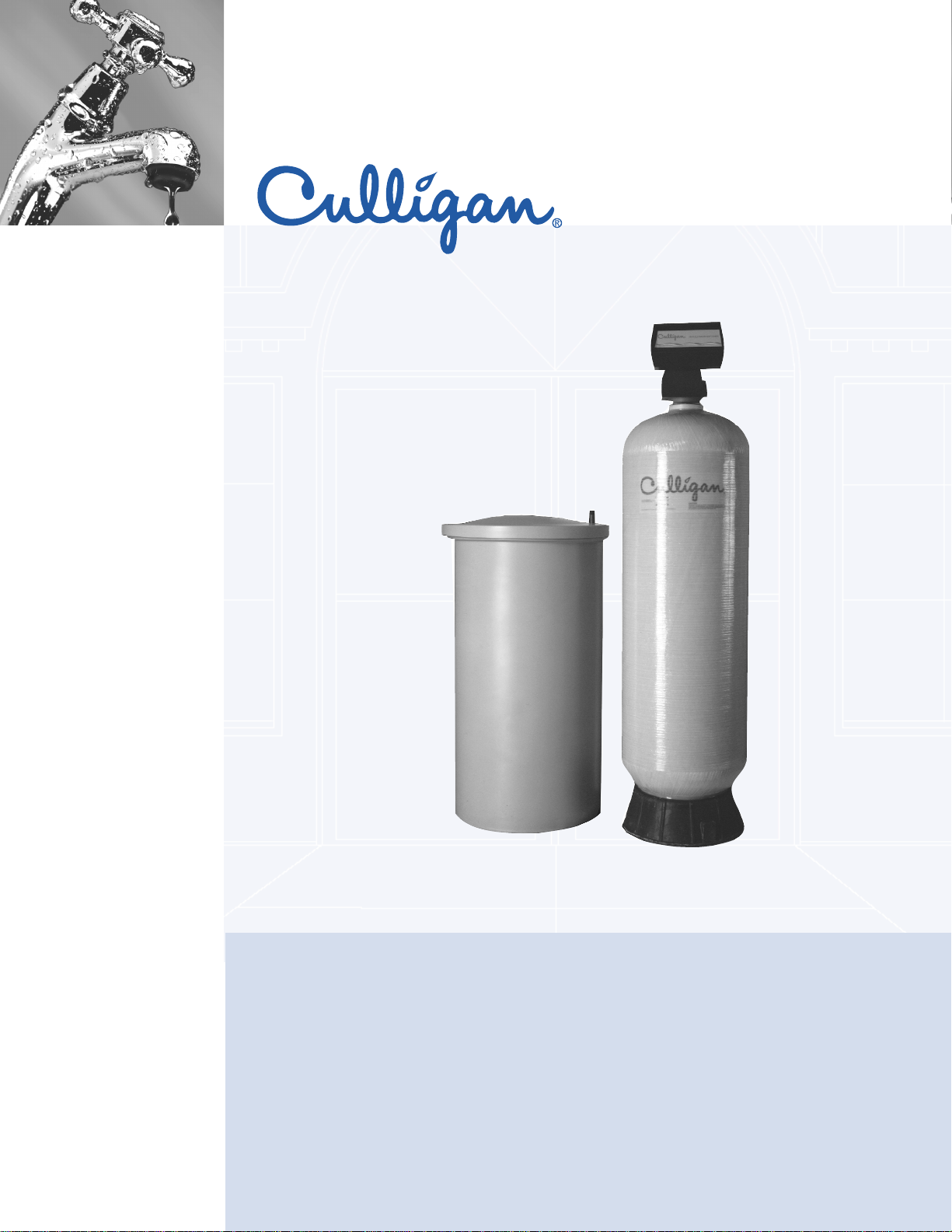
Hi-Flo
®
3 Automatic Water Softener
assisted living facilities
cafeterias
casinos
educational facilities
food service
grocery
hotel/ hospitality
institutions
laundry
corporate campuses
theme parks
vehicle wash
Culligan Hi-Flo®3 Water Softener Standard Features
• Positive Motor-Driven Regeneration Valve–Motor
driven piston is reliable under severe water conditions,
resists dirt, iron, turbidity.
• Automatic Brine Control—Automatically measures
the correct amount of brine. A single turn of dial sets
correct amount dosage and capacity.
• Dubl-Safe
™
Brine System—Positive overfill protection.
Automatic refill control is backed up by shutoff float
valve to minimize chance of overflow.
• Corrosion Resistant Tanks–made from fiberglassreinforced polyester. Additional reinforcement from
continuous fiberglass overwrap. Underdrain design
maximizes softener’s capacity, reduces pressure loss.
• Softening Media—High quality resin provides stability
and uniform size for top performance and long life.
• Choice of Cycle Controllers—Regeneration cycle may
be initiated by timeclock any or every day of the week.
Optional meter starts cycle after preset volume of
water has been softened.
More
Page 2
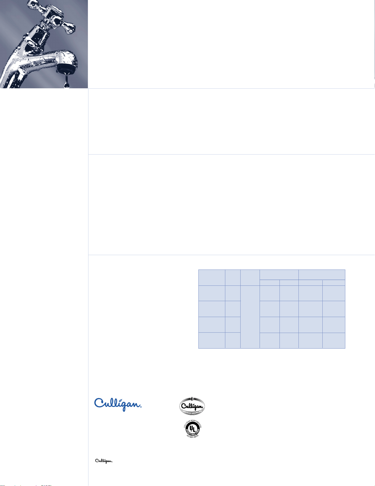
HC-150 5 60 78 21 x 54 24 x 48
HC-210 7 58 76 21 x 69 24 x 48
HC-300 10 65 85 24 x 72 30 x 48
HC-450 15 75 100 30 x 72 30 x 48
Model
Continuous* Peak**
Softener Brine
The Culligan Hi-Flo
®
3 Automatic Water Softener
System Specifications
Pressure: 30–120 psig
210–830 kPa
Vacuum: None
1
Temperature: 40–100°F
4 - 38°C
Electrical: 120V, 60 HZ
Turbidity: 5 NTU, max.
2
Chlorine: 1 mg/L, max.
2
Iron: 5 mg/L
1
Tank warranty is void if subject to vacuum
2
See media specification for details
***Flow rate at a 15 psi pressure loss.
***Flow rate at a 25 psi pressure loss.
***Dimensions are diameter by tank height.
Culligan Commercial @ Work
TM
www.culligan.com
1-800-CULLIGAN
©2001 Culligan International Co.
SL-0090 DCO 992824
Printed in USA (2/01)
MOORE PART NO.46956
“Hey Culligan Man!”
®
Resin
Qty.
(Ft
3
)
Flow Rates
Pipe
Size
Applications and Benefits
• RO/DI Pretreatment
• Apartment buildings, assisted living facilities and
hotels—Quality water for laundry, dishwashers,
boilers.
• Office buildings—For heating plant pretreatment,
tenant convenience, general housekeeping.
Hey Culligan Man, Culligan Man, Culligan Commercial @ Work, www.culligan.com
and Culligan Service Network are trademarks of Culligan International Company.
ISO 9001
Certification
SM
• Restaurants—For dishwashing, cleaning material
savings, scale reduction.
• Car washes—Quality results, detergent and water
heating savings, scale reduction.
• Light industry—For process and make-up water,
boiler and cooling system pretreatment, general
housekeeping.
Tank Size***
2″
Warranty
Culligan® Hi-Flo®3 water softeners are backed by a
limited 1-year warranty against defects in materials,
workmanship, and corrosion. The plastic conditioner
tank has a 5-year warranty. See printed warranty for
details.
*
Some localities have corrosive water. A softener cannot
correct this condition, so its printed warranty disclaims
liability for corrosion of plumbing lines, fixtures, or
water-using equipment. If you suspect corrosion, your
independently operated Culligan dealer has equipment
to control the problem.
*Culligan will provide a copy of warranties upon request.
The contaminants or other substances removed or reduced by
this water treatment device are not necessarily in your water.
Options
• Regeneration Flexibility—There are several choices
for regenerating a Hi-Flo
®
3 water softener to meet
your requirements. The simple, economical choice
is timeclock operation for both single and duplex
units. If water usage varies, meter operation is
available to signal regeneration immediately or
delay regeneration until a pre-set time. Duplex
meter operated units may be operated in parallel or
on an alternating basis, depending upon your needs.
Page 3
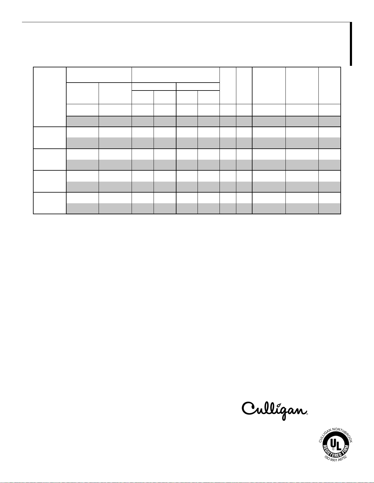
HI-FLO® 3
FULLY AUTOMATIC WATER SOFTENERS
SPECIFICATIONS AND OPERATING DATA
Single Exchange Capacity
1
Service Flow Rates
Tank @ Salt Dosage
Peak Continuous Softener Brine Approx.
Press. Press. Pipe Resin Tank Tank Ship.
Minimum Maximum Flow Drop Flow Drop Size Qty. Size Size Weight
gr @ lb gr @ lb gpm psi gpm psi in ft
Model g @ kg g @ kg m3/hr kPa m3/hr kPa in L mm mm kg
HC-150 100,000/30 150,000/75 78 25 60 15 2 5 21 x 54 24 x 48 540
6,480/14 9,720/34 17.7 172 13.6 103 2 142 530 x 1,370 610 x 1,200 46 0
HC-210 140,000/42 210,000/105 76 25 58 15 2 7 21 x 69 24 x 48 640
9,070/19 13,600/48 17.2 172 13.2 103 2 198 530 x 1,750 610 x 1,200 2 9 0
HC-300 200,000/60 300,000/150 85 25 65 15 2 10 24 x 72 30 x 48 865
12,960/27 19,400/68 19.3 172 14.7 103 2 284 410 x 1,830 760 x 1,200 39 5
HC-450 300,000/90 450,000/225 100 25 75 15 2 15 30 x 72 30 x 48 1,250
19,440/41 29,160/102 22.7 172 17.0 103 2 426 760 x 1,830 760 x 1,200 5 70
2
3
in in lb
1 Exchange capacities based on treating water containing 10 grains per gallon (171 mg/L) of hardness (expressed as calcium carbonate), free of color, oil, turbidity
and at a service flow rates not exceeding 20 gpm per square foot (49 m3/m2/min) of bed area. These are nominal capacities and will vary with influent water
characteristics, temperature, pressure and other factors.
2 Operation of a softener at peak flow rate for extended periods of time may result in a slight reduction of softening capacity. This is due to premature hardness
breakthrough.
NOTE: Operational, maintenance and replacement requirements are essential for this product to perform as advertised.
Specifications are shown for single models. Duplex models have two softener tanks and one brine tank system.
Commercial Systems
©2000 Culligan
1-800-CULLIGAN
www.culligan.com
Printed in USA 4/00
DCO 992587
SL-0074
Moore Part No. 46944
Page 4

Page 5

Hi-Flo 3
CAD File: Soft_HF3.dwg
Page 6

ENGINEER’S SPECIFICATION
More
AUTOMATIC WATER SOFTENER
HI-FLO® 3
1.0 SCOPE
1.1 Provide as indicated a vertical pres sure type water softener s ystem complete with pressure vessel, softening
resin, control valve, brine maker and controller. The system will be of an approved desi gn as fabricated by a
manufacturer regularl y engaged in the produc tion of wat er treatm ent eq uipm ent. All e qu ipment and m aterial will
be supplied in compliance with the specifications as intended for a complete and operational system.
¨ (Open Bidding Arrangement)
1.2 Qualif ied manuf acturers of water treatm ent equi pment of the type sp ecified are Culli gan Internati onal C ompan y
or the Engineer’s approved equal.
¨ (Closed Bidding Arrangement)
1.2 Qualif ied manuf acturer s of water soft ener equipm ent m us t be engaged in the m anuf acture of this equipm ent f or
a period of not less than fifteen (15) years. Accepta bl e manufacturers are Culli gan Int ernational Company or the
Engineer’s approved equal.
2.0 GENERAL DESCRIPTION
¨ (Selection for statement of specific model)
2.1 The system specifications are based on Culligan International model ________________________________.
The purpose of the Cu lligan International Ser ies Hi-Flo
hardness from a known water supply to a level not to exc eed ________ mg/l, as determ ined by an accepted
ASTM or EDTA test method, when the system is operated at ________ gpm and in accordance with the
operating instructio ns. The system will be capable of suppl ying ________ gallons of sof tened water between
regenerations based on the influent water analysis listed in Section 3.1 of this equipment specification.
CUSTOMER:
DATE:
3 automatic water softener will be to remove mineral
®
The systems perf ormance is rated at a desig n flow rate of ______ gpm with a rated pressur e drop of ______
psi, and will be cap able of a p eak flow ra te of _____ _ gpm for sustained periods of 90 m inutes with a pressur e
drop of ______ psi.
There shall be a quantity of ________ of the above described systems.
¨ (Selection for general statement)
2.1 The s ystem , in compliance with the equipm ent specification, is describ ed as an automatic __________ _____
water softener system meeting the performance and design data requirements as hereinafter specified.
3.0 PERFORM ANCE AND DESIGN DATA
3.1 INFLUENT WATER ANALYSIS
Calcium, Ca:
Magnesium, Mg:
Total Hardness:
(Constituents above are expressed in ppm or mg/l as CaCO3 or as otherwise specified.)
Iron, Fe:
Manganese, Mn:
Total Dissolved Solids, TDS:
(Constituents above are expressed in ppm or mg/l.)
Turbidity, NTU:
Color:
pH:
Page 7

3.2 DESIGN PARAMETERS
More
Normal System Flow & Pressure Drop: gpm @ 15 PSI
Maximum System Flow & Pressure Drop: gpm @ 25 PSI
Backwash/Rinse Flow: gpm
Backwash Volume: gallons nominal
Daily Water Usage: gallons per day (gpd)
Daily Hours of Water Demand:
Operating Temperature Range: 40°–100°F
Operating Pressure Range (System): 30–120 PSI
Electrical Requirements: 120 Volt, 60 Hz, 1 phase (receptacle required)
System Dimension (L x W x H): ”L x
¨ (ASTM soap test method)
3.3 EFFLUENT WATER QUALITY ZERO GPG HARDNESS
¨ (Hardness EDTA test method)
3.3 EFFLUENT WATER QUALITY MG/L HARDNESS
4.0 EQUIPMENT SPECIFICATIONS
4.1 SOFTENER TANK(S)
Each system shall include ____ _ tank(s). Each sof tener tank shall be ___ __ inches in diam eter. The sideshell
height shall be _____ inches, suf ficient to allow for proper f reeboard space above the res in bed for adequate
expansion of the resin during backwashing.
”W x ”H
4.1.0 Tank Construction
Tank(s) shall be manufactur ed of polyester reinforc ed by a continuous rov ing glass filam ent overwrap. T he top
opening will be 4”-8 UN threaded and the tank bottom will be supported on a molded structural base.
4.2 INTERNAL DISTRIBUTION
4.2.1 The upper distribution system shall be of the single point diffuser type to dispense water laterally to avoid
channeling within the resin bed.
4.2.2 The lower distribution system shall be of the s ingle point distributor t ype, constructed of PVC pipe a nd a fine
slotted strainer to provide even flow distribution through the resin bed. The distribution system shall be
embedded in a subfill of washed inorganic material to support the resin bed.
4.3 MAIN OPERATING VALVE
The main operating valve shall be of a top mount design constructed of all brass and sized with 2 inch NPT I
inlet and outlet connections.
The main operating valve will be of the motor dr iven, mechanically activated design with four (4) positions to
accomplish the reg eneration steps of backwash, brine draw/rinse and fast rinse/brin e refill, in addition to the
service position.
The main operating valve sha ll incorporate self adjusti ng flow regulat ors to control the r ate of flow and prevent
resin loss during backwash regardless of system pressure fluctuations between 30 and 120 psi.
The main operating valve will be fitted with a fixed orifice eductor.
¨ (Single units only – hard water bypass)
The unit shall be supplied so that the valve will allow aut omatic bypass of untreated water durin g regeneratio n.
The bypass shall be integral to the main operating valve body and be capable of being easily modified to
prevent hard water bypass.
¨ (Single units only – NO hard water bypass)
Culligan Hi-Flo® 3 Softener Engineer’s Specification Page 2
Page 8

The unit shall be supplied so that the valve will not allow automatic bypass of untreated water during
More
regeneration. The bypass shall be integral to the main operating valve body and be capable of being easily
modified to allow hard water bypass.
4.4 CONTROLS
The main operating valve will be contr o lled by an integral clock timer.
The controller sha ll sequence all s teps of an autom atic regenerat ion and autom atically r eturn the s oftener to a
service or stand-by mode.
The controller shall allo w for a manual initiation of the automatic regeneratio n sequence by utilizin g a manual
regeneration knob on the timer.
4.4.1 System control options
¨ (Time Clock, Single Unit)
A time-initiated re generation for sin gle units shall be available. T he clock timer will be capable of regener ating
the softener at any tim e of day or night and on an y or every day of the week. T he timer will activate a motor
drive that will perform the regeneration functions on the exhausted tank and return it to service.
¨ (Meter Initiated Delayed, Single Uni t)
A volumetric meter, mechanic ally coupled to the timer control, sh all set the timer for r egeneration at a preset
time of day or night after the preset volume of water has passed through the water softener. The timer will
activate a motor driv e that will perform the regeneration f unctions on the exhausted tank and return it t o the
service position.
¨ (Time Clock, Parallel Twin Unit)
A time-initiated regeneration for parallel twin units shall be available. Each clock timer will be capable of
regenerating the softener at any time of day or night and on any or every day of the week. The timer will
activate a motor drive th at wi l l per f orm the regeneration funct ions o n the exhausted tank and r eturn it to service.
Simultaneous regener ati ons sha ll not be pos s ib le.
¨ (Meter Initiated, Parallel Twin Unit)
Each unit shall include a vol um etric meter, m echanically cou pled t o the tim er control. Up on exh austi on of either
tank, its control shall ac tivate a m otor drive t hat wil l im m ediately, or at a pres et tim e of day or nig ht, per form the
regeneration functions on the exha usted tank and return it to the serv ice position. T he controls s hall includ e an
electrical interlock to prevent simultaneous regeneration of both softeners in the event the second tank
exhausts while the first tank is in regeneration.
¨ (Meter Initiated, Alternating Twin Unit)
A single, remote mounted volum etr ic meter shall s ignal t he sof ten ers to r egener ate on a n a lternati ng bas is after
the preset volume of water has passed through the water softener. One unit remains in a fully regenerated
stand-by condition while the other unit is in servic e. Upon exhaustion of the ser vice unit, the s tand-by un it shall
immediately be placed into serv ice and the exhauste d unit shal l be rem oved from service and the r egeneration
initiated. The tim er will activat e a m otor dr ive that will perf orm the r egeneratio n f unctio ns on the exha usted tank
and return it to the stand-by position. No exter n al alt er nat ing de vices will be accep tab le. The alternating function
must be contained in t he sequencing controller and each controller mus t communicate via a single pre-wired
cable assembly, simultaneous regenerations shall not be possible.
¨ (Meter Initiated systems ONLY)
4.4.2 Flow Meter(s)
¨ (Meter Initiated single and parallel systems ONLY)
A flow meter package shall be provided consisting of a mechanical turbine-type meter; the package shall
include a total of _____ meter assemblies.
The meter provided s ha ll be 2.0 inc hes , compatible with the s pecified piping. It wil l be designed to allow ease of
removal of the turbine for ins pection without modification of the p iping s ys tem. A cable shall be provided for
direct connection to the operating valve.
The meter package provid ed shall be f unction al within the flo w range of 3 to 130 gpm and will be pro vided wit h
a threaded tee meter fitting.
Culligan Hi-Flo® 3 Softener Engineer’s Specification Page 3
Page 9

¨ (Meter Initiated alternating system ONLY)
One remote mounted mechanical turbine-type meter will be provided.
The meter provided s ha ll be 2.0 inc hes , compatible with the s pec ified piping. It will be d es ig ned to a ll o w eas e of
removal of the turbine for ins pection without modification of the piping system. The meter will be electrically
connected to the cycle timer.
The meter provided shall be functional within the flow range of 3 to 130 gpm and will be provided with a
threaded tee meter fitting.
4.5 EXCHANGE RESIN
The ion exchange resin shall be virg in hig h cap acit y “stand ard m es h” of s ulfonated po l yst yrene type s tabl e over
the entire pH range with good resistance to bead fracture fr om attrition or osmotic shock. Each cubic foot of
resin will be capable of removing 30,0 00 grains of hardness as calcium carbonate when regenerated with 15
lbs. of salt. The r esin shall be solid, of the proper particle size of 20-50 m esh, U.S. standard scr een and will
contain no agglomerates, shells, plates or other shapes that might interfere with the normal function of the water
softener. The resin shall be manufactur ed to com ply with the food additive regulation 21 CFR 173.25 as set
forth by the USFDA.
The system shall includ e _____ c ubic feet of exchang e resin per vessel and a t otal of __ ___ cubic feet of resin
for the system.
4.6 BRINE SYSTEM
Provide a complete brine syst em consis ting of a plast ic tank, salt platf orm, br ine well, an autom atic brine valve
and all necessar y fittings f or oper atio n with t he water soft ening system . T he s ystem shall c ons ist of a com bined
brine measuring an d s alt s tor ag e ta nk with salt platform. The tank will be si zed _ ___ inc h es x __ ___ inches; the
system will include a total of _____ brine tank(s).
The brine tank will be equipped with a float operated non-corrosive field serviceable brine float valve for
automatic control of brine withdrawal and fresh water refill.
The brine valve will automatic ally open to admit brine to the resin tank during eduction and close autom atically
providing positi ve shut-off to prevent air f rom enterin g the system . The brine va lve will also r egulate the f low of
soft water into the br ine tank during r efill. T he brine va lve works with the tim ed fill featur e of the m ain o perating
valve controls to admit the correct vo lume of fresh water to th e brine tank in accorda nce with the s alt dosage
setting on the controls. The brine valve will include a float operat ed safety shut-off valve as a b ack up to the
timed refill from the main operating valve control to prevent brine tank overflow.
4.7 ACCESSORIES
(All Optional selections)
4.7.1 ¨ Water test kits for hardness tests will be supplied.
4.7.2 ¨ Pressure Gauges for hard water inlet and soft water outlet.
4.7.3 ¨ Sampling Cocks for hard water inlet.
4.7.4 ¨ Vacuum Breaker for protecting Fiberglass tanks from vacuum.
5.0 INSTRUCTIONS
_____ complete sets of installation, operating and maintenance manuals shall be provided.
6.0 FIELD SERVICE
The services of a f actory authorized service represen tative can be made available to super vise, inspect and
provide operator tra ining as req uired for ini tial s tart-u p and s yst em operation. Co ntact your loc al C ulli gan dealer
for service rates and scheduling.
7.0 WARRANTY
A single written warranty must be provided from the manufacturer of the water softener system covering
workmanship and materials.
Rev. 11/00
Culligan Hi-Flo® 3 Softener Engineer’s Specification Page 4
 Loading...