

Culligan Aqua-Cleer Series Installation, Operation & Service Instructions With Part List

Cat. No. 01020219
Rev. C 05/28/09
DCO # 010836
Installation, Operation
& Service Instructions
with Parts List
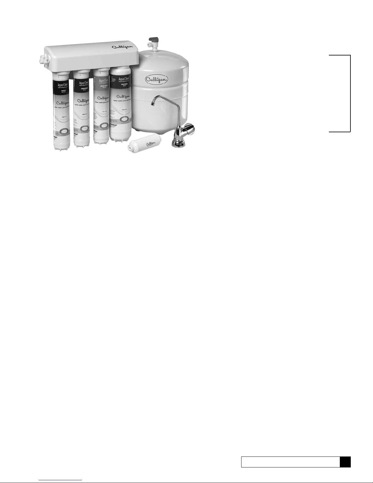
Culligan® Aqua-Cleer
Advanced Drinking
Water Systems
Models from 2008
®
© 2008 Culligan International Company
Attention Culligan Customer:
Your local independently operated Culligan dealer employs trained service and maintenance personnel who are experienced
in the installation, function and repair of Culligan equipment. This publication is written specifically for the purpose of training
and guiding these individuals and is intended for their use.
We encourage Culligan users to learn about Culligan products, but we believe that product knowledge is best obtained by
consulting with your Culligan dealer. Untrained individuals who use this manual assume the risk of any resulting property
damage or personal injury.
These systems are intended for use on potable water supplies or disinfected water containing cysts. Do not use where water
is microbiologically unsafe or with water of unknown quality. If bacterial contamination is present, a recognized method of
water disinfection is required.
Check with your public works department for applicable local plumbing and sanitation codes. Follow your local codes if they
differ from the standards used in this manual.
For installations in Massachusetts: Massachusetts Plumbing Code 248 CMR shall be adhered to. Consult your
licensed plumber for installation of this system. The use of saddle valves is not permitted in Massachusetts.
The Aqua-Cleer® system contains a replaceable reverse osmosis membrane filter which is critical for the effective reduction
of Total Dissolved Solids. The filtered water should be tested periodically to verify that the system is performing properly.
Safe Practices
Throughout this manual there are paragraphs set off by special headings.
Note: Note is used to emphasize installation, operation or maintenance information which is important, but does not present
any hazard. Example:
Note: The nipple must extend no more than 1 inch above the cover plate.
Caution!: Caution is used when failure to follow directions could result in damage to equipment or property. Example:
Caution! Disassembly while under water pressure can result in flooding.
Warning!: Warning is used to indicate a hazard which could cause injury or death if ignored. Example:
Warning! Electrical shock hazard! Unplug the unit before removing the timer mechanism or cover plates!
Serial Numbers
The serial number is located on the rear of the R.O. manifold housing.
Note: Do not remove or destroy the serial number. It must be referenced on requests for warranty repair or replacement.
Culligan International Company
9399 West Higgins Road, Suite 1100
Rosemont, Illinois 60018
847.430.2800
www.culligan.com
This publication is based on information available when approved for printing. Continuing design refinement could cause
changes that may not be included in this publication.
Warning! If incorrectly installed, operated or maintained, this product can cause severe injury. Those who
install, operate, or maintain this product should be trained in its proper use, warned of its dangers, and
should read the entire manual before attempting to install, operate or maintain this product.
ii Culligan® Aqua-Cleer® Drinking Water Systems
Installation, Operation
& Service Instructions
with Parts List
Culligan® Aqua-Cleer
Advanced Drinking
Water Systems
®
Models from 2008
Table of Contents
Page
Specifications . . . . . . . . . . . . . . . . . . . . . . . . . . . . . . . . . . . . . . . . 2
Suggested Installation Equipment . . . . . . . . . . . . . . . . . . . . . . . . 3
Product Information . . . . . . . . . . . . . . . . . . . . . . . . . . . . . . . . . . . 4
Component Description . . . . . . . . . . . . . . . . . . . . . . . . . . . . . . . . 5
Part Numbers . . . . . . . . . . . . . . . . . . . . . . . . . . . . . . . . . . . . . . . . 7
In-Plant Preparation . . . . . . . . . . . . . . . . . . . . . . . . . . . . . . . . . . . 8
Installation . . . . . . . . . . . . . . . . . . . . . . . . . . . . . . . . . . . . . . . . . .12
Performance and Technical Information . . . . . . . . . . . . . . . . . . .21
Service and Maintenance. . . . . . . . . . . . . . . . . . . . . . . . . . . . . . .29
Troubleshooting . . . . . . . . . . . . . . . . . . . . . . . . . . . . . . . . . . . . . . 32
Parts List . . . . . . . . . . . . . . . . . . . . . . . . . . . . . . . . . . . . . . . . . . .34
Aqua-Cleer System Performance Worksheet . . . . . . . . . . . . . . .37
Mounting Bracket Template . . . . . . . . . . . . . . . . . . . . . . . . . . . . .39
Table of Contents 1
Specifications
Typical System Flow Sequence . Particle Filter, Activated Carbon Filter, Reverse Osmosis Membrane, Specialty Filter,
Storage Tank, Polishing Filter, Dispensing Faucet
Particle Filter. . . . . . . . . . . . . . . . . 1, 2 or 3
Activated Carbon Filter . . . . . . . . Activated Carbon or Activated Carbon Block
Reverse Osmosis Membrane . . . Culligan® Aqua-Cleer® Thin Film Composite
Production Rate1 . . . . . . . . . . . . . Aqua-Cleer 30 Models 36 gpd (119 L/day)
. . . . . . . . . . . . . . . . . . . . . . . . . . . . Aqua-Cleer 50 Models 50 gpd (189 L/day)
Ratio of Product to Flush Flow
. . . . . . . . . . . . . . . . . . . . . . . . . . . . Standard Applications 1:3 - 1:5 (Aqua-Cleer-30 models only)
. . . . . . . . . . . . . . . . . . . . . . . . . . . . Soft Water Applications 1:1
Polishing Filter . . . . . . . .. . . . . . . Activated Carbon or Carbon Block
Specialty Cartridges
3
. . . . . . . . . . . . . . . . . . . . . . . . . . . . Arsenic Cartridge 1000 gallons
. . . . . . . . . . . . . . . . . . . . . . . . . . . . Total Defense (MTBE, VOC Reduction) 1000 gallons
. . . . . . . . . . . . . . . . . . . . . . . . . . . . Perchlorate Cartridge* 1000 gallons
Dispensing Faucet . . . . . . . . . . . . Culligan Aqua-Cleer Faucet: Rotary Operation, Stainless Steel and Resin Flow Passages,
. . . . . . . . . . . . . . . . . . . . . . . . . . . . Colors Brushed Nickel, Polished Chrome or White
Storage Capacity
. . . . . . . . . . . . . . . . . . . . . . . . . . . . Standard Tank 2 gallons (7.5 L)
. . . . . . . . . . . . . . . . . . . . . . . . . . . . Medium Tank 3 gallons (10.5 L)
. . . . . . . . . . . . . . . . . . . . . . . . . . . . Large Tank 9 gallons (34 L)
Dimensions
. . . . . . . . . . . . . . . . . . . . . . . . . . . . Filter Assembly 13.8” W x 4.2” D x 15.5” H (35 cm W x 10.7 cm D x 39.4 cm H)
. . . . . . . . . . . . . . . . . . . . . . . . . . . . Storage Tank • Std. 9” Diameter x 15”H (23 cm Diameter x 38 cm H)
• Med. 11” Diameter x 15”H (28 cm Diameter x 38 cm H)
• Lrg. 15.5” Diameter x 22”H (40 cm Diameter x 56 cm H)
2
with Built-in Siphon Break
1 Rating at 50 psi, 77°F, 500 mg/L TDS influent, without storage tank.
2 May vary with pressure. See “Replace Flow Control”, page 10, for all hard water applications and applications where TDS
exceeds 1000 mg/L (ppm).
3 Arsenic and Perchlorate cartridge must be installed after the RO membrane and system must have a Performance
Indicator Device (PID) installed to track gallon usage.
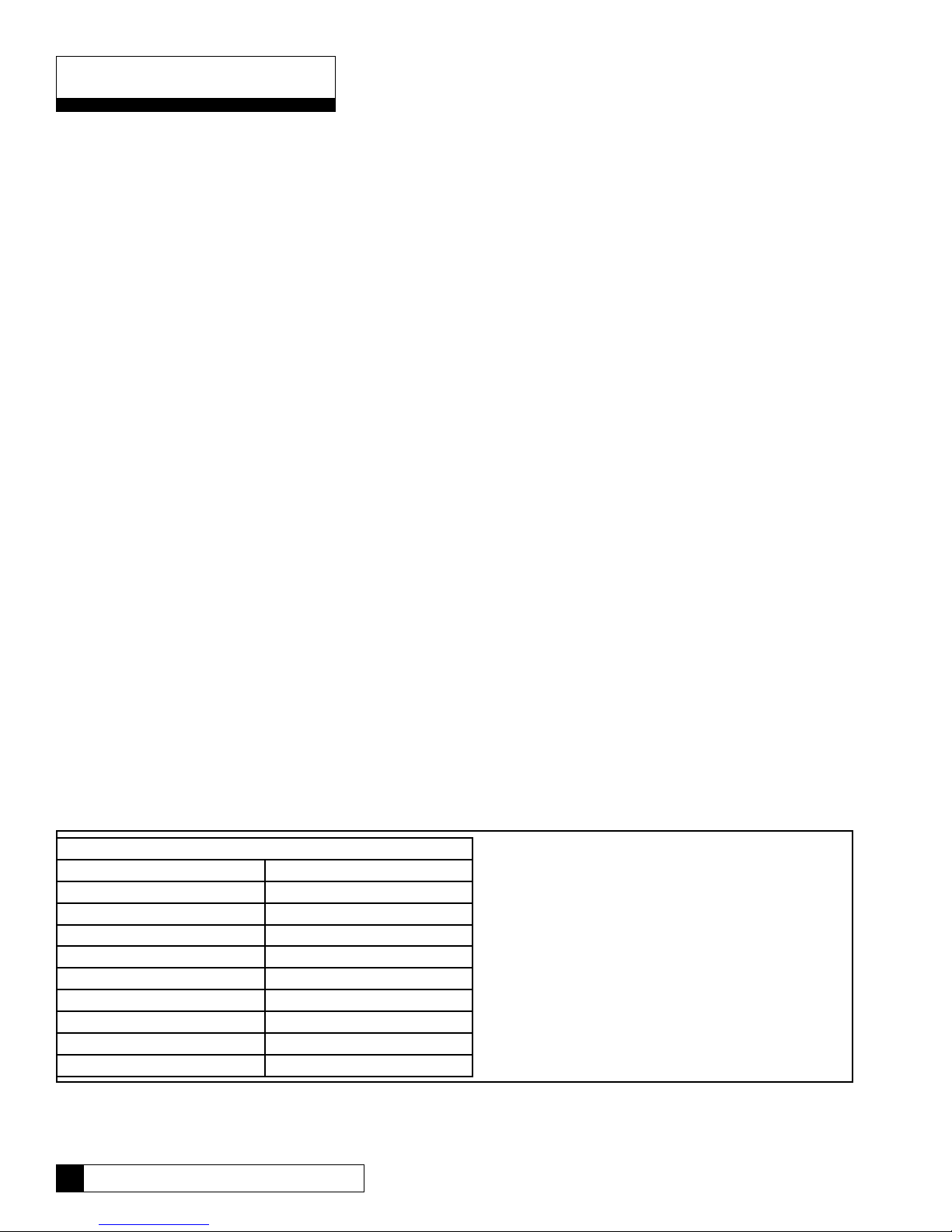
Influent Water Characteristic
Pressure 40 - 120 psi
Temperature 33 - 100 ºF
Total Dissolved Solids (TDS)10 - 2500 ppm (0 - 2500 mg/L)
pH 5 - 10
Chlorine
2
0 - 3 ppm (0 - 3 mg/L)
Chloramine 0 - 3 ppm (0 - 3 mg/L)
Turbidity 0 - 10 NTU
Hardness
3
0 - 10 gpg
Iron 0 - 1 ppm (0 - 1 mg/L)
Bacterial Quality Potable
* Cartridge not for sale in California.
Notes
1. See the “Performance & Technical Information” section for all
applications where TDS exceeds 1000 ppm. A booster is strongly
recommended to improve the reduction of TDS. Higher pressures
will help maintain the membrane’s maximum rejection performance.
2. The reverse osmosis membrane used in these systems may be
damaged by chlorine. These systems include activated carbon
filters which protect the membranes by reducing chlorine. Influent
chlorine should not exceed 3 mg/L.
3. A softener is strongly recommended for water over 10 gpg hard.
Installing a system without a softener on water with hardness higher
than 10 gpg will reduce the life of the membrane.
4. Additional information on factors that affect RO performance can be
found in the “Performance & Technical Information” section.
Table 1
2 Culligan® Aqua-Cleer® Drinking Water Systems

Suggested Installation Equipment
Sink Cutting Tools
Porcelain Cutter Kit, 1-1/4 inch diameter, PN 00591625
Greenlee Hole Punch, 1-1/4 inch diameter
Plumbers Putty
Heavy Duty Drill with speed control to 400 rpm
Tools
Screwdriver, blade and Phillips (#1)
1/8 inch diameter pilot drill for #10 screws
Center Punch
Razor Blade Knife
Accessories/Hardware
Tubing, Plastic, 1/4-inch, PN 00402184 Blue
Tubing, Plastic, 3/8-inch, PN 01000287 Blue
Piercing Valve, PN 01000889
Drain Saddle Kit, PN 42000001
Silicone Lubricant, PN 00471507
Thread Sealing Tape
TDS Meter, PN D0470504
Graduated Measuring Cylinder
Thermometer, PN 00470501
Stopwatch, or wristwatch with second hand
Chlorine Bleach (Clorox* unscented household, 5-1/4% strength) or sanitizer packet
Eye dropper (available at drug store)
Pressure Gauge (0-120 psi) with section of 1/4” OD tubing connector
#10 Screws, type determined by mounting surface and material
Tee, PN P1004728, if system will be connected to icemaker
Miscellaneous
Extension Work Light
Air Pressure Gauge
Air Pump (bicycle tire pump)
Furniture pad for Back Protection
Small Portable Blower for Ventilation
*Clorox is a registered trademark of the Clorox Company.
Suggested Installation Equipment 3

Product Information
This manual covers the technical aspects of Culligan® Aqua-Cleer® drinking water systems. It is important to read this manual
thoroughly so that you can properly apply, install, and service these systems.
The substances reduced by this system are not necessarily in the customer’s untreated water. See Performance Data Sheet
(located in the Owners Guide) for exact percentages of contaminant removal.
System Configuration
The 4-Port manifold system is designed with the flexibility to allow for multiple filter and membrane configurations.
Packaging
The Aqua-Cleer system is shipped from the factory in cartons:
Carton 1
• Manifold Assembly
• Parts Package, including:
Tank Valve
• Product Literature
Carton 2-6
• Particle Filter or
• Pre-Carbon Filter (Carbon Block or
Granular Activated Carbon)
• Reverse Osmosis Element (36
gpd, 50 gpd or Nanofilter*)
• Total Defense (MTBE, VOC
Reduction)
• Arsenic Cartridge
• Perchlorate Cartridge*
• Post Carbon Filter
Carton 7-
• Storage Tank
Carton 8-
• Faucet
Carton 9-
• Aqua-Cleer Sentry® Monitor
Note: The filter elements are shipped in their own sealed packaging. This will help to simplify in-plant preparation of the
system and to maximize the shelf life of the RO membrane element.
If the Aqua-Cleer system will not be installed immediately, refrigerate the RO membrane element at 35°/40°F (2°/5°C).
DO NOT ALLOW TO FREEZE.
Warranty
A limited warranty is extended to the original end user from Culligan. This warranty is printed on the back cover of the Owner’s
Guide.
Application Guidelines
The Aqua-Cleer system is designed for use on potable water supplies meeting the guidelines outlined in Table 1. The system
should be installed on a home’s cold water line. The flushing stream should discharge through an approved siphon break.
Installation of this system must comply with state and local laws and regulations.
High Efficiency Operation
The Aqua-Cleer system has an option high-efficiency operation. Soft water use is strongly recommended. For maximum RO
membrane life on all hard-water installations, substitute the flow control as described in the “In-Plant Preparation” section of
this manual.
* Cartridges not for sale in California.
4 Culligan® Aqua-Cleer® Drinking Water Systems
11
10
6
9
8
5
2
4
3
7
3/8” Outlet
1/4” Inlet
1
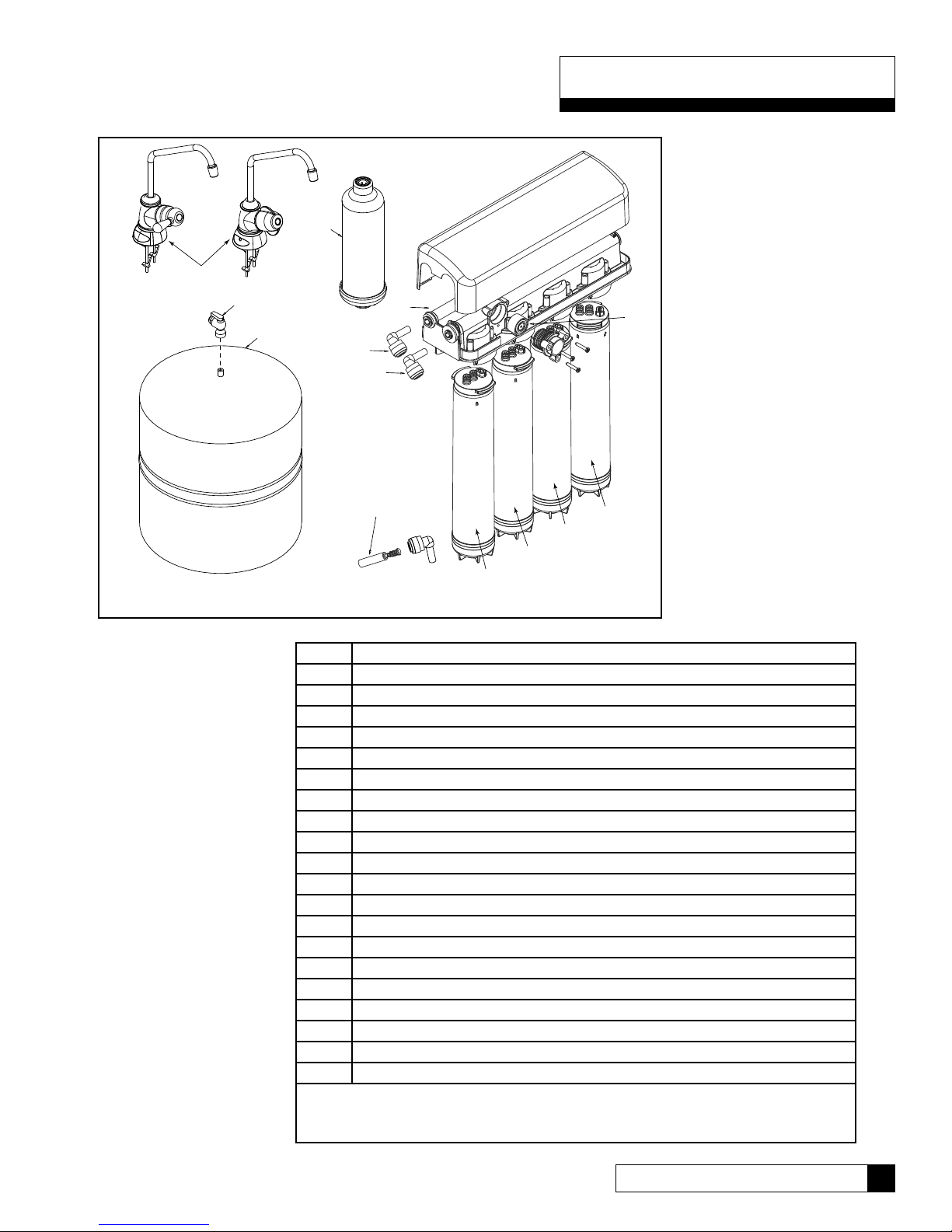
Component Description
Item Description
10 2 Gallon Storage Tank
11 Ball Valve
*Monitor (Not Shown)
**Cartridges not for sale in California
= Cartridge not for sale in California or Iowa
Figure 2
1 Manifold Assembly
2 SED 1 Sediment Filter
SED 2 Sediment Filter
SED 3 Sediment Filter
3 Carbon Block Filter
Granular Activated Carbon Filter
4 30 GPD Reverse Osmosis Membrane
50 GPD Reverse Osmosis Membrane
Nanofiltration Reverse Osmosis Membrane=
5 Arsenic Filter
Perchlorate Filter**
Carbon Block Filter (MTBE, VOC)
6 Post Carbon Filter
7 Flow Control
8 Automatic Shut-off Valve
9 Faucet
3 Gallon Storage Tank
9 Gallon Storage Tank
Component Description 5

Manifold/Main Filter Assembly (Refer to Figure 2 for component description.)
• Manifold Assembly
The manifold assembly serves as the functional hub of the Aqua-Cleer system by directing the flow through each of the
system’s main components.
• Particle Filter
The particle filter (2) is melt blown and is closed at one end. The particle filter screens out particulate material, such as
dirt, sand, or rust, which may clog the other filters in the system. The filter is available in either SED 1, SED 2, SED 3.
• Activated Carbon Filter (prior to Reverse Osmosis Membrane - #3)
The activated carbon filter (3) is offered in two styles, granular or block. Both are rated to treat 2000 gallons of water
containing 2.0 ppm of chlorine. The active material is acid washed activated carbon. The activated carbon filter reduces
chlorine which may damage the RO membrane filter. It must be regularly checked and or replaced to prevent premature
membrane failure.
• Reverse Osmosis Membrane (#4)
The RO membrane (4) reduces dissolved substances and other microscopic impurities such as arsenic, lead, sodium,
and others. It consists of a membrane envelope wound around a perforated tube. Product water diffuses through the
membrane to the inside of the envelope where it flows to and is collected by the tube. Impurities are flushed away in the
concentrate stream.
The RO membrane featured in the Aqua-Cleer system offers exceptional contaminant rejection, application versatility,
and long life. The membrane material is sensitive to an attack by chlorine. The activated carbon filter must be maintained
properly to prevent premature failure of the RO membrane.
Note: This preservative must be flushed from membrane before use. If ingested it may cause irritation of the
gastrointestinal tract, colic, diarrhea, or other similar symptoms. The manufacturer recommends discarding all the
product water for at least one hour of operation before drinking or use in food preparations. Culligan highly recommends
discarding the product water for a full 24 hours to flush the preservative and to properly hydrate the membrane for
maximum performance. The flushing procedure is on page 10.
(#1)
(#2)
• Flow Control Assembly (#7)
The flow control assembly or concentrate flow control (7) regulates the flow rate of the flushing (concentrate) stream and to
maintain pressure in the RO membrane filter. It is located at the bottom of the reverse osmosis element. The assembly can
be adjusted to change the rate of the concentrate stream. The substitution procedure is on page 10.
Note: Changing the flow control voids the NSF listing. Remove the NSF data label from the system if you adjust the
flow control. Changing the flow control voids the California Department of Public Health Certifications.
• Automatic Shutoff (#8)
The automatic shutoff (8) automatically stops the flow of water through the Aqua-Cleer system when the storage tank
is full.
• Storage Tank
The storage tank (10) collects and stores the water produced by the RO system. A compressed air diaphragm drives
the water to the polishing filter and faucet. The ball valve (11) provides a convenient way to lock water in the tank during
transport and filter changes.
• Polishing Filter
The polishing filter (6) adsorbs any residual tastes and odors just before the water is delivered through the faucet.
6 Culligan® Aqua-Cleer® Technical Manual

• Aqua-Cleer Sentry™ Monitor
This optional monitor (figure 1) accessory checks the TDS level of the drinking water each time the dispenser faucet is
used. A green LED indicator mounted in the faucet signals if the TDS level is below the setpoint, an red signal appears if it
is above.
• Dispenser Faucet (#9)
The Aqua-Cleer faucet (9) allows the product water to be
drawn from the system with a simple rotation of the handle. It
features a built-in siphon break for concentrate discharge as
required by most plumbing codes.
To help assure quick and trouble-free installation of the Aqua-
Cleer® system, the preparation steps should be performed
in the dealer facility. Cleanliness is essential in the InPlant Preparation procedure. Be sure to wash your hands
thoroughly before handling filters. The use of surgical gloves
is strongly recommended.
Figure 1
Component Description 7
In-Plant Preparation
Tubing Connectors
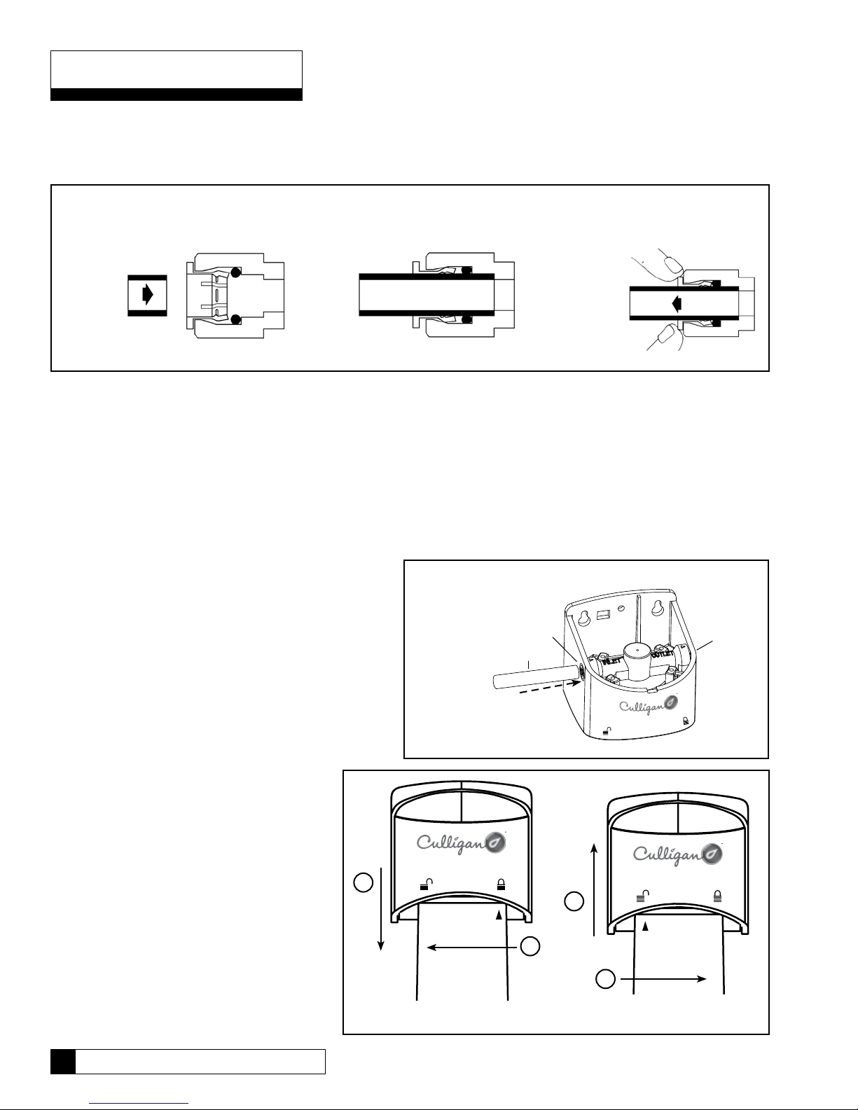
The Aqua-Cleer® system features reliable and convenient push-to-connect (figure 3) tubing connectors. Tubing is easily
connected and disconnected from these fittings as follows.
Quick-Connect Fitting
Insertion & Removal of Plastic or
Copper Tubing
1. Simply
push in
tube to
attach.
Connect:
Cut the tubing squarely with a sharp knife. Be careful not to crush the tubing. To avoid leaks, make sure the tubing end is
smooth and free of burrs and abrasions. Lubricate the end of the tube with water or a light coat of silicone and push the tube
end firmly into the fitting. You should feel it push past the O-ring. Avoid bending the tubing sharply away from the fitting.
2. Tube is secured in position. 3. Push in collet from both sides to
release tubing.
Figure 3
Disconnect:
Hold the collar against the fitting body and pull the tube from the fitting.
In the unlikely event that the connection leaks, remove
and recut the tubing. Check the inside of the fitting for
debris or O-ring damage. Reconnect.
Push-to-connect tubing connectors grip the outside
diameter of the tube. To help assure a reliable
connection, it is important to use high quality tubing with
a consistent outside diameter. Culligan recommends
that the tubing listed in the “Suggested Installation
Equipment” section of this manual (page 3) be used with
the Aqua-Cleer system.
Figure 4
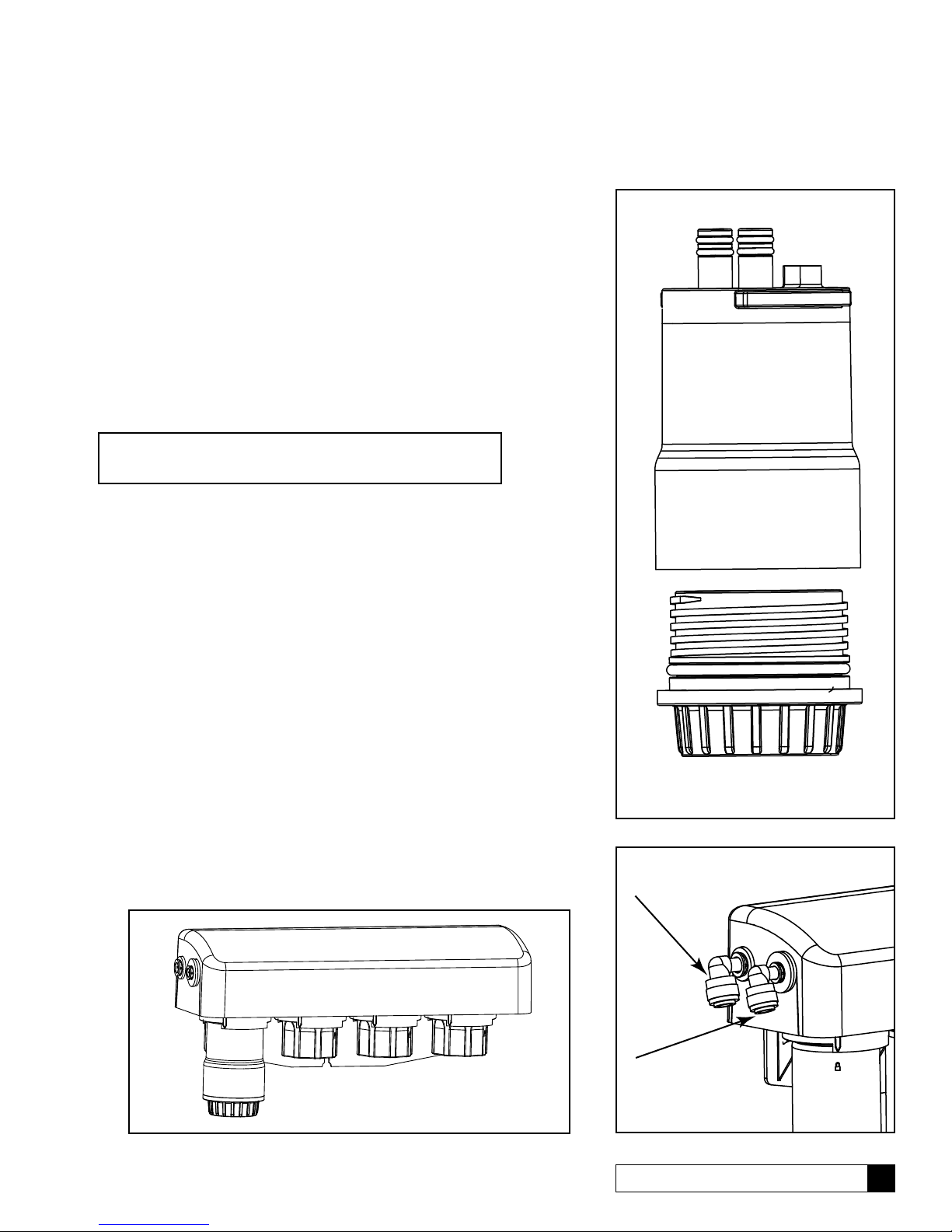
Filter Assembly Preparation
Activated Carbon Filter
The activated carbon filter must be thoroughly
flushed to remove carbon dust which can plug
the manifold or RO membrane.
To perform this procedure, it is necessary to use
a clean single head cartridge assembly.
1. Install 1/4” tubing to the inlet and outlet
of the single head cartridge assembly
(figure 4).
2. Install the activated carbon cartridge into
the single head cartridge
assembly (figure 5).
b
Insert
a
Figure 5
Inlet
Outlet
a
b
8 Culligan® Aqua-Cleer® Drinking Water Systems
3. Connect the inlet of the single head cartridge assembly to a source of clean,
1/4” - Raw / Inlet
3/8” - Product Water
filtered water.
4. Connect the outlet of the service housing to a suitable drain.
5. Slowly turn on the water and flush the filter for 5 minutes at a rate of 1-2
gpm (4-7 L/min). Turn the water on and off several times during flushing to
help loosen carbon particles from the filter.
6. Once flushed, the filter should be placed in service within 24 hours.
7. Remove the activated carbon filter cartridge from the service housing and
set it aside in a clean location for installation into the Aqua-Cleer system.
8. Reattach protective cap.
Sanitize Manifold Assembly
The Aqua-Cleer system may be sanitized with either sanitizer packet, 5-1/4%
liquid chlorine unscented bleach or sanitizer.
Note: The storage tank should also be sanitized at this time.
Pour two tablespoons liquid chlorine bleach into the sanitizer cartridge
1.
(figure 6A).
Assemble the cartridge to the 1st position in the manifold.
2.
Using 1/4” OD plastic tubing, connect the inlet of the system (figure 7) to a
3.
source of clean filtered water (RO or DI water, if available).
Connect 3/8” OD plastic tubing from the product water outlet to a 3/8” Tee.
4.
Connect the other ends of the Tee to the storage tank and 3/8” shut-off.
Install bypass plugs in the remaining cartridge positions (figure 6B).
5.
Turn on the supply valve, open the tank valve and 3/8” shut-off valve and
6.
allow the system to fill with water.
Once water begins to flow from the shut-off valve, turn off the supply valve
7.
and close the shut-off valve.
Allow the system to sit for ten minutes.
8.
Turn on the supply valve and flush the sanitizing solution from the system.
9.
The water coming from the storage tank should have a chlorine odor. If not,
10.
repeat steps 1-9 until it does.
Fill and empty the tank (steps 3,6,9) until only a faint chlorine odor remains.
11.
The polishing filter will remove any residual chlorine taste once the system
is installed.
Figure 6A
Figure 6B
Figure 7
In-Plant Preparation 9
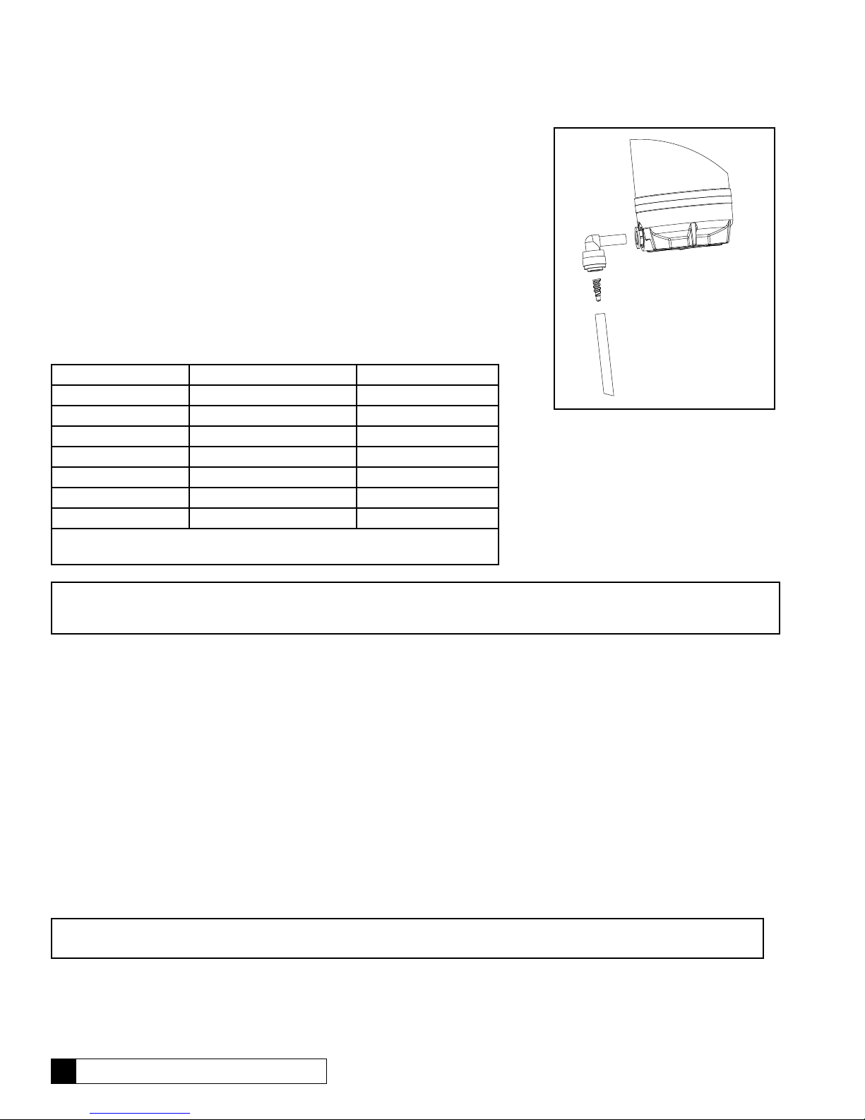
Replacing the Flow Control
The concentrate water flow control is shipped with the reverse osmosis cartridge
(it is taped to the cartridge). Follow the procedure below to install the flow control:
1. Insert the flow control into the inlet of the ¼” concentrate tubing.
2. Insert the tubing into the elbow located at the bottom of the reverse osmosis
cartridge (figure 8).
The Aqua-Cleer system is designed for a 35% recovery. For maximum efficiency
on most softwater installations the standard flow control assembly can be
replaced with a 50% recovery flow control assembly. Use the 25% recovery
flow control assembly on high hardness and/or high TDS. Follow the above
procedure to replace the flow control.
Unit Recovery Flow Control Color
Aqua-Cleer-30 25% Orange
Aqua-Cleer-30 35% (shipped w/ cartridge) Red
Aqua-Cleer-30 50% Green
Aqua-Cleer-50 25% White
Aqua-Cleer-50 35% (shipped w/ cartridge) Black
Aqua-Cleer-50 50% Yellow
Nanolter* 35% (shipped w/ cartridge) White
Note: The same white flow control is used for the Aqua-Cleer 50 at 25%
recovery and Nanofilter.
Figure 8
Note: Changing the flow control, shipped within the unit, voids the NSF listing. Remove the NSF data label from the system
if you adjust the flow control. Changing the flow control voids the California Department of Public Health Certifications.
Flush RO Membrane
The RO membrane must be flushed prior to use.
1. Turn on the supply valve to the system.
2. Allow the product water and flushing water to flow to a suitable drain for 24 hours.
3. Reattach protective cap.
Check Performance
Check the performance of the system according to the procedure beginning on page 21 of this manual.
Storage Tank Preparation
Note: Changing the air pressure will alter the amount of water stored in the tank. Increasing the pressure will decrease
capacity while decreasing pressure will increase capacity.
* Cartridge not for sale in California or Iowa.
10 Culligan® Aqua-Cleer® Drinking Water Systems

Check Air Pressure
Using a tire gauge with 1 psi increments, check the air pressure in the empty storage tank. The air pressure should be between
5 and 15 psi, for the 2, 3 and 9 gallon storage tanks. Depending on the influent water pressure the air pressure may need to be
adjusted. Refer to page 25 to determine the optimal air pressure setting. To modify the air pressure use a bicycle-type hand
pump to increase the air pressure or depress the stem of the air valve to decrease the pressure.
Install Tank Shut-off Valve
Use a high quality, food-grade thread sealant or PTFE tape to assemble the valve onto the tank.To avoid future leaks, do not
over tighten the plastic valve onto the tank.
Sanitize the Storage Tank
The storage tank must be flushed and sanitized prior to installation. See page 9 for sanitization procedure.
Fill the Storage Tank (optional)
So that your customers can begin using their new Aqua-Cleer system immediately upon installation, you may wish to fill the
storage tank with RO product water. Once the in-plant preparation of the Filter Assembly (prior section) is complete, proceed
as follows:
Warning! Do not use the tank ball valve to lift or carry the tank.
1. Connect a length of 3/8” OD plastic tubing between the tank ball valve and the product water fitting (figure 9) on the
manifold.
2. Using 1/4” OD plastic tubing, connect the system inlet to a water source meeting the characteristics listed in Table 1.
3. Using 1/4” OD plastic tubing, connect the concentrate outlet to a suitable drain.
4. Turn on the water supply, open the tank ball valve, and allow the tank to fill (3-4 hours).
5. Once the tank is full, close the tank ball valve and disconnect the system so that it can be transported to the
installation site.
Polishing Filter Preparation
The polishing filter must be flushed prior to use to remove any carbon dust generated during shipment.
1. Using 3/8” OD plastic tubing, connect the inlet of the filter to a source of clean filtered water (RO or DI water, if available).
Observe the direction of flow arrow on the filter.
2. Turn on the water supply and flush the filter for 5 minutes. Cycle the water on and off approximately 10 times during the 5
minute flush.
3. Turn off the water supply, disconnect the filter, and set aside for final installation.
4. Once flushed, the filter should be put into service within 24 hours.
In-Plant Preparation 11
 Loading...