

Culligan 9, 10"", 14"", 12 Owner's Manual
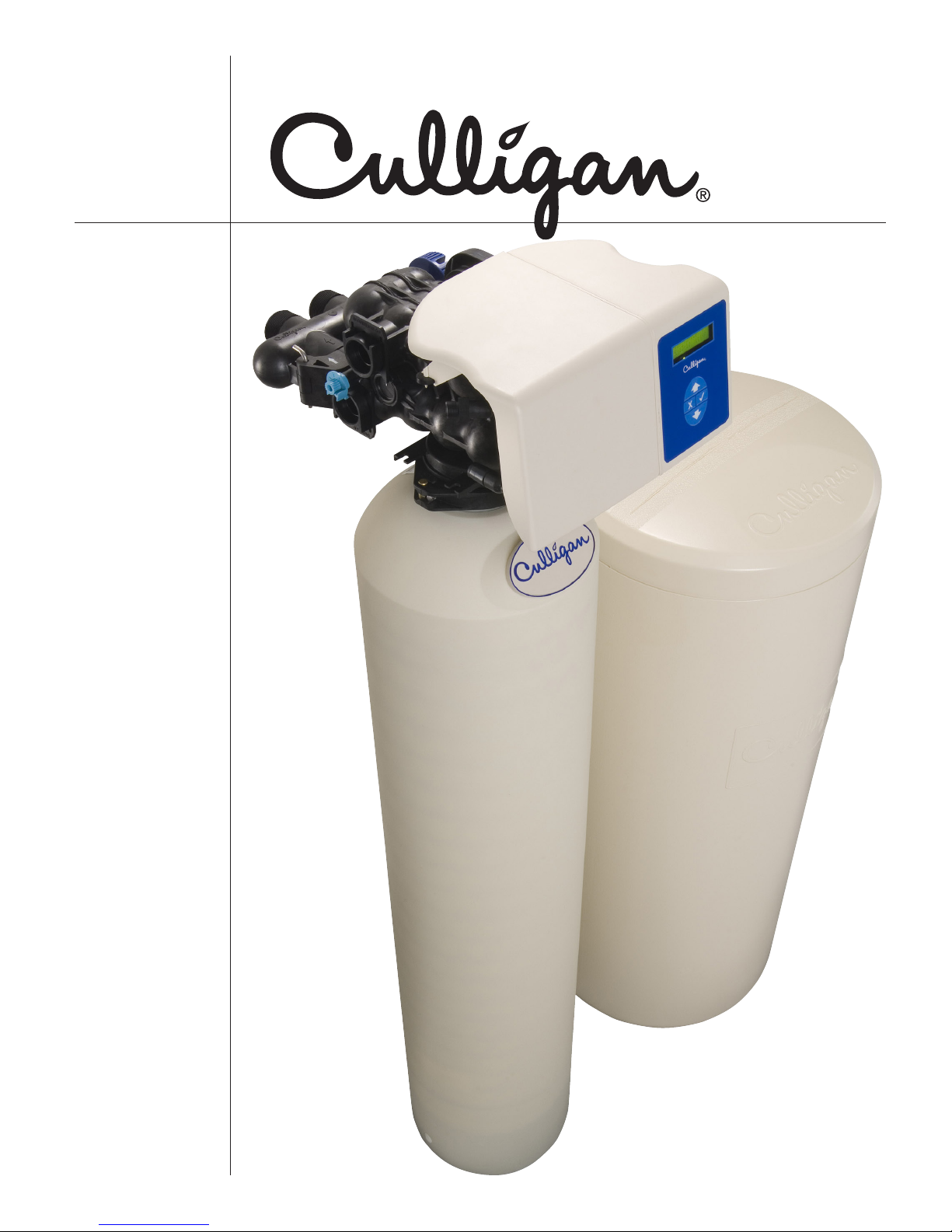
Culligan®
High
Efficiency
Automatic
Water
Softener
Owners
Guide
Attention
Culligan
Customer
The installation, service and maintenance of this equipment should be rendered by a qualified and trained
service technician. Your local independently operated Culligan dealer employs trained service and maintenance personnel who are experienced in the installation, function and repair of Culligan equipment. This
publication is written specifically for these individuals and is intended for their use.
We encourage Culligan users to learn about Culligan products, but we believe that product knowledge is
best obtained by consulting with your Culligan dealer. Untrained individuals who use this manual assume
the risk of any resulting property damage or personal injury.
WARNING! Electrical shock hazard! Prior to servicing equipment, disconnect
NOTE This system is not intended for use where water is microbiologically unsafe or with
water of unknown quality.
WARNING! If incorrectly installed, operated or maintained, this product can cause
WARNING! This device complies with part 15 of the FCC rules subject to the
power supply to prevent electrical shock.
severe injury. Those who install, operate, or maintain this product
should be trained in its proper use, warned of its dangers, and
should read the entire manual before attempting to install, operate,
or maintain this product.
two following conditions: 1) This device may not cause harmful
interference, and 2) This device must accept all interference received
including interference that may cause undesired operation.
This equipment complies with Part 15 of the FCC rules. Any changes or modifications not expressly approved by the manufacturer could void the user’s authority to operate the equipment. Changes or modifications not expressly approved by the party responsible for compliance could void the user’s authority to
operate the equipment.
CAUTION! To reduce the risk of fire, use only No. 26 AWG or larger
CAUTION! This product is not to be used by children or persons with reduced
telecommunications line cord.
physical, sensory or mental capabilities, or lack of experience or
knowledge, unless they have been given supervision or instruction.
Products manufactured and marketed by Culligan International Company (Culligan) and its affiliates are
protected by patents issued or pending in the United States and other countries. Culligan reserves the right
to change the specifications referred to in this literature at any time, without prior notice. Culligan, AquaSensor, Tripl-Hull, and SoftMinder are trademarks of Culligan International Company or its affiliates.
i
01021076
CAUTION! Children should be instructed not to play with this appliance.
CAUTION! If the power cord from the transformer to the unit looks or becomes
damaged, the cord and transformer should be replaced by a Culligan
Service Agent or similarly qualified
person in order to avoid a hazard.
Culligan International Company
9399 West Higgins Road, Suite 1100
Rosemont, Illinois 60018
1-847-430-2800
www.culligan.com

Thank You ................................................................................................................................... 1
Specifications .............................................................................................................................. 2
Introduction ................................................................................................................................. 5
How Your Water Conditioner Works .............................................................................................. 6
The Culligan Process .................................................................................................................... 7
Modes of Operation ..................................................................................................................... 8
Installation ................................................................................................................................. 10
Programming ............................................................................................................................ 27
Maintenance ............................................................................................................................ 40
Sanitizing Procedure ................................................................................................................. 43
Things to Check Before You Call for Service .................................................................................. 44
Error Codes ............................................................................................................................... 45
When and How to Bypass Your Water Conditioner ....................................................................... 47
Performance Data Sheet
Culligan High Efficiency 9” Water Softener with Soft-Minder® Meter ............................................. 48
Culligan High Efficiency 9" Water Softener with Aqua-Sensor® Sensing Device .............................. 49
Culligan High Efficiency 10" Water Softener with Soft-Minder® Meter ........................................... 50
Culligan High Efficiency 10" Water Softener with Aqua-Sensor® Sensing Device ............................ 51
Culligan High Efficiency 12" Water Softener with Soft-Minder® Meter ........................................... 52
Culligan High Efficiency 12" Water Softener with Aqua-Sensor® Sensing Device ............................ 53
Culligan High Efficiency 14” Water Softener with Soft-Minder® Meter ........................................... 54
Culligan High Efficiency 14” Water Softener with Aqua-Sensor® Sensing Device ............................ 55
Culligan High Efficiency 9” Upflow Water Softener with Soft-Minder® Meter .................................. 56
Culligan High Efficiency 9” Upflow Water Softener with Aqua-Sensor® Sensing Device ................... 57
Culligan High Efficiency 10” Upflow Water Softener with Soft-Minder® Meter ................................ 58
Culligan High Efficiency 10” Upflow Water Softener with Aqua-Sensor® Sensing Device ................. 59
Culligan High Efficiency Municipal 9" Water Softener ................................................................ 60
Culligan High Efficiency Municipal 10" Water Softener .............................................................. 61
Culligan High Efficiency Municipal 12” Water Softener .............................................................. 62
Culligan High Efficiency Municipal 14” Water Softener .............................................................. 63
California Department of Public Health Certificate .......................................................................... 64
Important Data on Your Water Softener ........................................................................................ 68
Electrical Schematic .................................................................................................................... 69
Parts List .................................................................................................................................... 70
Culligan Limited Warranty .......................................................................................................... 77
Index ........................................................................................................................................ 79
Contents
01021076
ii
About this
Manual
This manual:
• familiarizes the operator with the equipment
• explains installation and setup procedures
• provides basic programming information
• explains the various modes of operation
• gives specifications and troubleshooting information
Read this Manual First
Before you operate the Culligan High Efficiency Automatic Water Softener, read this manual to become
familiar with the device and its capabilities.
Safe Practices
Throughout this manual there are paragraphs set off by special headings.
Notice (or Note) is used to emphasize installation, operation or maintenance information which is important, but does not present any hazard. For example,
NOTICE The nipple must extend no more than 1 inch above the cover plate.
Caution is used when failure to follow directions could result in damage to equipment or property.
CAUTION! Disassembly while under water pressure can result in flooding.
Warning is used to indicate a hazard which could cause injury or death if ignored.
WARNING! Electrical shock hazard! Unplug the unit before removing the
timer mechanism or cover plates!
The CAUTION and WARNING paragraphs are not meant to cover all possible conditions and situations
that may occur. Understand that common sense, caution, and careful attention are conditions which
cannot be built into the equipment. These MUST be supplied by the personnel installing, operating, or
maintaining the system.
Be sure to check and follow the applicable plumbing codes and ordinances when installing this equipment. Local codes may prohibit the discharge of sanitizing or descaling solutions to drain.
Use protective clothing and proper face or eye protection equipment when handling chemicals or tools.
NOTE The Culligan High Efficiency Softener is not intended for use with water that is
microbiologically unsafe or of unknown quality without adequate disinfection
either before or after the system.
NOTE Check with your public works department for applicable local plumbing and
sanitation codes. Follow local codes if they differ from the standards used in
this manual. To ensure proper and efficient operation of the Culligan High
Efficiency Filter to your full satisfaction, carefully follow the instructions in this
manual.
iii
01021076
Welcome To Your New World of Better Living with Culligan Water.
The Culligan HE Water Softeners with Soft-Minder® Meter and Aqua-Sensor® sensing device are tested and certfied by WQA against NSF/ANSI Standard 372, CSA
B483.1, and NSF/ANSI Standard 44 for the effective reduction of hardness (calcium
and magnesium), barium, and radium 226/228, as verified and substantiated by test
data.
The Culligan HE Municipal Water Softeners are tested and certified by WQA against
NSF/ANSI Standard 372, CSA B483.1, and NSF/ANSI Standard 44 for the effective
reduction of hardness (calcium and magnesium), and NSF/ANSI Standard 42 for the effective reduction
of Chlorine Taste and Odor, as verified and substantiated by test data.
The Culligan HE Water Softener Outdoor Controller Enclosure complies with the UL 50/50E and UL 746C
standards for a NEMA 3R Enclosure Rating.
For installations in Massachusetts, Massachusetts Plumbing Code 248 CMR shall be adhered to. Consult your licensed plumber for installation of this system. This system and
its installation must comply with state and local regulations. The use of saddle valves is
not permitted.
If this is your first experience having soft, conditioned water in your home, you’ll be amazed at the marvelous difference it makes. We promise that you’ll never want to be without it again.
Congratulations, too, on selecting one of the “first family” of water conditioners in the prestigious Culligan
High Efficiency Water Softeners. With Culligan’s many years of knowledge and experience in water treatment, you can be confident that the model you selected has been designed and engineered to provide
years of service with a minimum of care and attention.
Some localities have corrosive water. A water softener cannot correct this problem and so its printed
warranty disclaims liability for corrosion of plumbing lines, fixtures or appliances. If you suspect corrosion,
your Culligan Dealer has equipment to control the problem.
Thank You
NOTICE Sodium Information: Water softeners using sodium chloride for regenera-
tion add sodium to the water. Persons who are on sodium restricted diets
should consider the added sodium as part of their overall sodium intake.
Serial Numbers
The control valve serial number is located on the back of the timer case.
The media tank serial number is located on the top surface of the tank.
NOTE DO NOT remove or destroy the serial number. It must be referenced on
request for warranty repair or replacement.
01021076
1
Specifications
2
01021076
Culligan High Efciency Water Conditioners with
Aqua-Sensor® Device or Soft-Minder® Meter—Downow Regeneration
Model 9" Model 10" Model 12" Model 14" Model
Control Valve 1” Reinforced Thermoplastic w/ HE Circuit Boards
Overall Conditioner Ht 56 in 62 in 60 in 73 in
Media Tank Design Quadra-Hull™
Media Tank Dimensions
(Dia x Ht)
Salt Storage Tank Dimensions (Dia x Ht)
Exchange Media, Type
and Quantity
Underbedding, Type and
Quantity
Exchange Capacity @ Salt
Dosage Per Recharge
Efficiency rated dosage
Freeboard to Media
Freeboard to
Underbedding
1
2
3
Salt Storage Capacity 250 lb or 375 lb 250 lb or 375 lb 375 lb 600 lb
Rated Service Flow @ Pressure Drop
Auxiliary Flow Rate
4
Total Hardness, Maximum 75 gpg 99 gpg 99 gpg 99 gpg
Total Iron, Maximum 5 ppm
Hardness to Iron Ratio,
Minimum
Operating Pressure 20-125 psi (138–862 kPa)
Operating Pressure
(Canada)
Operating Temperature 33-120°F (0–49°C)
Electrical Requirements 24V/60 Hz
Electrical Power Consumption, Min/Max
Drain Flow, Maximum
5
Recharge Time, Average6
Recharge Water
Consumption, Average
1
The efficiency rated dosage is only valid at the stated salt dosage and is efficiency rated according to NSF/ANSI Standard 44.
2
Measured from top of media to top surface of tank threads (backwashed and drained).
3
Measured from top of underbedding to top surface of tank threads.
4
Auxiliary flow rates do not represent the maximum service flow rate used for determining the softener’s rated capacity and efficiency and that continuous
operation at these flow rates greater than the maximum service flow rate may affect capacity and efficiency performances.
5
Backwash at 120 psi.
6
10 minute backwash, 4 lb. 9” model, 6 lb. 10” model, 7 lb. 12” model, or 12 lb. 14” model salt dosage.
6
9 x 48 in 10 x 54 in 12 x 52 in 14 x 65 in
16 x 43 in
or 18 x 43 in
16 x 43 in
or 18 x 43 in
18 x 43 in 24 x 42 in
Cullex® Media,1.0 ft3Cullex Media, 1.5 ft3Cullex Media, 2.0 ft3Cullex Media, 3.0 ft
Cullsan®
Underbedding, 12 lb
Cullsan
Underbedding, 15 lb
Cullsan
Underbedding, 20 lb
Cullsan
Underbedding, 25 lb
17,854 gr @ 4.0 lb 26,781 gr @ 6.0 lb 31,352 gr @ 7.0 lb 51,726 gr @ 12 lb
27,108 gr @ 8.0 lb 40,662 gr @ 12.0 lb 48,458 gr @ 16.0 lb 75,582 gr @ 24 lb
31,736 gr @ 12.0 lb 47,604 gr @ 18.0 lb 59,267 gr @ 18.0 lb 88,549 gr @ 36 lb
4,463 gr/lb @ 4 lb
salt dosage
4,463 gr/lb @ 6 lb
salt dosage
4,479 gr/lb @ 7 lb
salt dosage
4,310 gr/lb @ 12 lb
salt dosage
14.5 in 14.5 in 16 in 25 in
44.5 in 47.5 in 46 in 59 in
9.0 gpm @ 11 psi 9.4 gpm @ 12 psi 10.0 gpm @ 10 psi 10.6 gpm @ 11 psi
10.8 gpm @ 15 psi 11.0 gpm @ 15 psi 12.6 gpm @ 15 psi
12.8 gpm @ 15 psi
8 gpg to 1 ppm
20-90 psi (138–621 kPa)
8.4 watts/21.6 watts
2.5 gpm 2.5 gpm 3.0 gpm 5.3 gpm
78 minutes 67 minutes 62 minutes 76 minutes
47 gallons 45 gallons 67 gallons 155 gallons
3
Culligan High Efciency Softener—Upow Regeneration
Model 9" Model 10" Model
Control Valve 1” Reinforced Thermoplastic with HE Circuit Board
Overall Conditioner Height 56 in 62 in
Media Tank Design Quadra-Hull™
Media Tank Dimensions (Dia x Ht) 9 x 48 in 10 x 54 in
Salt Storage Tank Dimensions (Dia x Ht) 16" x 43" or 18" x 43"
Exchange Media, Type and Quantity Cullex® Media, 1.0 ft
3
Cullex Media, 1.5 ft
Underbedding, Type and Quantity Cullsan® Underbedding, 12 lb Cullsan Underbedding, 15 lb
Exchange Capacity @ Salt Dosage Per Recharge 9,792 gr @ 2.0 lb 30,081 gr @ 6.0 lb
17,366 gr @ 4.0 lb 47,726 gr @ 12.0 lb
27,306 gr @ 8.0 lb 54,975 gr @ 18.0 lb
Efficiency rated dosage1 4,896 gr/lb @ 2 lb salt dosage 5,014 gr/lb @ 6 lb salt dosage
Proportional Brining Efficiency Rating2 5,760 gr/lb @ 2 lb salt dosage 5,898 gr/lb @ 6 lb salt dosage
Freeboard to Media3 14.5 in 14.5 in
Freeboard to Underbedding4 44.5 in 47.5 in
Salt Storage Capacity 250 lb or 375 lb
Rated Service Flow @ Pressure Drop 9.0 gpm @ 11 psi 9.4 gpm @ 12 psi
Auxiliary Flow Rate
5
10.8 gpm @ 15 psi 11.0 gpm @ 15 psi
Total Hardness, Maximum 30 gpg
Total Iron, Maximum 2 ppm
Hardness to Iron Ratio, minimum 8 gpg to 1 ppm
Operating Pressure 20-125 psi (138–862 kPa)
Operating Pressure (Canada) 20-90 psi (138–621 kPa)
Operating Temperature 33-120°F (0–49°C)
3
Electrical Requirements 24V/60 Hz
Electrical Power Consumption, Min/Max 8.4 watts/21.6 watts
Drain Flow, Maximum6 2.2 gpm 2.3 gpm
Recharge Time, Average7 Recharge Water 68 minutes 57 minutes
Consumption, Average7 (Evaluated by WQA) 33 gallons 35 gallons
Consumption, Average8 (Not evaluated by WQA) 25.5 gallons 27.5 gallons
1
The efficiency rated dosage is only valid at the stated salt dosage and 5-minute backwash. It is efficiency rated according to NSF/ANSI 44.
2
The Proportional Brining Efficiency Rating assumes a 20 percent reserve capacity at the time of regeneration that is typical of what the manufacturer expects
under real-world operation. Proportional brining is not measured by NSF/ANSI 44, and so this cliam is not, and can not, be rated to NSF/ANSI 44.
3
Measured from top of media to top surface of tank threads. (backwashed and drained).
4
Measured from top of underbedding to top surface of tank threads.
5
Auxiliary flow rates do not represent the maximum service flow rate used for determining the softener’s rated capacity and efficiency and that continuous
operation at these flow rates greater than the maximum service flow rate may affect capacity and efficiency performances.
6
Backwash at 35 psi (830 kPa).
7
5 minute backwash, 2 lb. 9" model, 6 lb. 10" model. These values have been tested and certified by WQA.
8
2 minute backwash, 2 lb. 9” model, 6 lb. 10” model. These values are based on the manufacturer recommended backwash time.
01021076
3
Culligan HE Municipal Water Softener
9" Model 10" Model 12" Model 14" Model
Control Valve 1”, 5-cycle Reinforced Thermoplastic with Global Electronic (GBE) Circuit Board
Overall Conditioner Height 54 in 60 in 58 in 71 in
Media Tank Design Quadra-Hull™
Media Tank Dimensions (Dia
x Ht)
Salt Storage Tank Dimensions
(Dia x Ht)
Exchange Media, Type and
Quantity
Carbon Media, Quantity 6 lbs 8 lbs 12 lbs 18 lbs
Underbedding, Type and
Quantity
Exchange Capacity @ Salt
Dosage Per Recharge
Efficiency rated dosage1
Chlorine Taste and Odor
Capacity
Freeboard to Media2 15.75 in 19.5 in 17.31 in 25.89 in
Freeboard to Underbedding3 44.5 in 47.5 in 46 in 59 in
9 x 48 in 10 x 54 in 12 x 52 in 14 x 65 in
16 x 43 in or
18 x 43 in
Cullex® Media,
0.8 ft3
Cullsan®
Underbedding, 12 lb
16 x 43 in
or 18 x 43 in
Cullex® Media,
1.0 ft3
Cullsan®
Underbedding, 15 lb
18 x 43 in 24 x 42 in
Cullex® Media,
Cullex® Media,
1.5 ft3
Cullsan®
Underbedding, 20 lb
Underbedding, 25 lb
2.3 ft3
Cullsan®
17,119 gr @ 4.0 lb 21,399 gr @ 5.0 lb 29,062 gr @ 7.0 lb 39,118 gr @ 9.0 lb
25,232 gr @ 8.0 lb 31,540 gr @ 10.0 lb 43,990 gr @ 18.0 lb 59,297 gr @ 18.0 lb
27,806 gr @ 12.0 lb 34,758 gr @ 15.0 lb 49,343 gr @ 30.0 lb 71,448 gr @ 28.0 lb
4,280 gr/lb @
4 lb salt dosage
4,280 gr/lb @
5 lb salt dosage
4,152 gr/lb @
7 lb salt dosage
4,346 gr/lb @
9 lb salt dosage
300,000 gallons 339,000 gallons 621,000 gallons 935,000 gallons
Salt Storage Capacity 250 lb or 375 lb 375 lb 650 lb
Rated Service Flow @
Pressure Drop
9.0 gpm @ 12 psi 9.4 gpm @ 11 psi 10.0 gpm @ 11 psi 10.6 gpm @ 11 psi
Total Hardness, Maximum 15 gpg
Total Iron, Maximum 0 ppm
Color Less Than 1
Turbidity Less Than 5 NTU
TOC Less Than 0.5 PPM
Operating Pressure 20-125 psi (138–862 kPa)
Operating Pressure (Canada) 20-90 psi (138–621 kPa)
Operating Temperature 33-120°F (0–49°C)
Electrical Requirements 24V/60 Hz
Electrical Power Consumption,
Min/Max
8.4 Watts/21.6 Watts
Drain Flow, Maximum4 2.6 gpm 2.6 gpm 3.2 gpm 6.2 gpm
Recharge Time, Average5
Recharge Water
78 min 67 min 62 min 76 min
Consumption, Average5 70 gal 70 gal 97 gal 162 gal
1
The efficiency rated dosage is only valid at the stated salt dosage and is efficiency rated according to NSF/ANSI 44.
2
Measured from top of media to top surface of tank threads. (backwashed and drained).
3
Measured from top of underbedding to top surface of tank threads.
4
Backwash at 120 psi (830 kPa).
5
4
01021076
10 minute backwash, 4 lb. 9” model, 5 lb. 10” model, 7 lb. 12” model, or 9 lb. 14” model.
It’s All So Easy, So Economical, So Efficient, So Enjoyable!
Kind To Skin And Complexion
Soft water will help prevent red, itchy or dry skin because there are no hardness impurities to cause soreness, no soap curd to coat the skin. Shaving is easier, smoother—either with a blade or electric shaver.
Bathing And Showering
You’ll use far less soap with conditioned water. Use your soap very sparingly—not as you did before soft
water. Just a quick rinse removes all lather, leaving your skin pleasantly smooth and silky because now it’s
free of sticky soap curd and film.
Saves Washing Costs. Helps Control Environmental Pollution
Soft water washes whiter and cleaner with less soap or detergent. Because the hardness impurities are removed, your soap can concentrate solely on washing. People usually find that they can reduce the amount
of soap they use substantially. If you normally use a cup per wash load with hard water, try using 1/3 cup
depending on the size of your wash load and the degree of soil. Different amounts are required, but you
can use less with softened water. An added bonus is the fact that your washable fabrics will last longer.
Super Hair Conditioning
Soft water is great for scalp and hair care. No insoluble deposits are formed. Hair is shinier, softer, more
manageable. Reduce the amount of shampoo you have normally used.
Dishes Are A Delight
Washed by hand or in a dishwasher, glassware, dishes and silver wash cleaner, easier. Follow your
dishwasher manufacturer’s instructions. Soft water promotes sanitation because no greasy hard water film
can form to collect or harbor bacteria.
Introduction
Easier Housekeeping, Gleaming Fixtures
You’ll be amazed at the marvelous difference. Just a swish of the cloth, and the bathtub or shower and
fixtures are clean and sparkling. Imagine, no scouring! No hard water scum to cause rings, streaks, spots
and stains. To keep their gleaming luster, simply wipe fixtures with a towel after use. Formica, tile, walls,
floors, woodwork surfaces clean easier, stay clean longer. You’ll save on cleaning aids and save on time.
Saves Water-Heating Energy, Helps Water-Using Appliances
Soft water reduces the formation of rock-like hard water scale that encrusts water heaters, hot water pipes,
shower heads, and water-using appliances. This scale can cause premature maintenance and failure.
Elimination of hard water also provides substantial energy savings because scale acts as an insulator,
wasting electricity or gas used to heat water.
Water For Lawns And Household Plants
If possible, lawn sprinkling faucets should be supplied with hard water primarily because it is uneconomical to soften so much water.
Household plants are much more sensitive than lawns with respect to the kind of water which is best. First,
because they receive no rainfall and, second, there is little or no drainage of the soil. Preferably they
should be watered with rainwater or water which is low in mineral content such as distilled or demineralized water. Softened water is not recommended for house plants because a build-up of sodium in the soil
may interfere with efficient absorption of water by the plant root system. Additional information may be
obtained from your independently operated Culligan dealer.
Culligan Municipal Softener
With the Culligan Municipal softener you will experience the above benifits in addition to the reduction of
chlorine taste and odor for a fresh, clean taste and smell.
01021076
5
How Your
Water
Conditioner
Works
Why Water Gets Hard And How It Is Softened
All of the fresh water in the world originally falls as rain, snow, or sleet. Surface water is drawn upward
by the sun, forming clouds. Then, nearly pure and soft as it starts to fall, it begins to collect impurities as it
passes through smog and dust-laden atmosphere. And as it seeps through soil and rocks it gathers hardness, rust, acid, unpleasant tastes and odors.
Water hardness is caused primarily by limestone dissolved from the earth by rainwater. Because of this,
in earlier times people who wanted soft water collected rainwater from roofs in rain barrels and cisterns
before it picked up hardness from the earth.
Some localities have corrosive water. A softener cannot correct this problem and so its printed warranty
disclaims liability for corrosion of plumbing lines, fixtures or appliances. If you suspect corrosion, your
Culligan Man has equipment to control the problem.
Iron is a common water problem. The chemical/physical nature of iron found in natural water supplies is
exhibited in four general types:
1. Dissolved Iron—Also called ferrous or “clear water” iron. This type of iron can be removed
from the water by the same ion exchange principle that removes the hardness elements, calcium
and magnesium. Dissolved iron is soluble in water and is detected by taking a sample of the
water to be treated in a clear glass. The water in the glass is initially clear, but on standing
exposed to the air, it may gradually turn cloudy or colored as it oxidizes.
2. Particulate Iron—Also called ferric or colloidal iron. This type of iron is an undissolved par-
ticle of iron. A softener will remove larger particles, but they may not be washed out in regeneration effectively and will eventually foul the ion exchange resin. A filtering treatment will be
required to remove this type of iron.
3. Organic Bound Iron—This type of iron is strongly attached to an organic compound in the
water. The ion exchange process alone cannot break this attachment and the softener will not
remove this type of iron.
4. Bacterial Iron—This type of iron is protected inside a bacteria cell. Like the organic bound
iron, it is not removed by a water softener.
When using a softener to remove both hardness and dissolved iron it is important that it regenerates more
frequently than ordinarily would be calculated for hardness removal alone. Although many factors and
formulas have been used to determine this frequency, it is recommended that the softener be regenerated
when it has reached 50–75% of the calculated hardness alone capacity. This will minimize the potential
for bed fouling. (Iron removal claims have not been verified by the Water Quality Association.)
If you are operating a water softener on clear water iron, regular resin bed cleaning is needed to keep the
bed from coating with iron. Even when operating a softener on water with less than the maximum of dissolved iron, regular cleanings should be performed. Clean every six months or more often if iron appears
in your conditioned water supply. Use resin bed cleaning compounds carefully following the directions on
the container.
6
01021076
CAUTION! Do not use where the water is microbiologically unsafe or
with water of unknown quality without adequate disinfection
before or after the unit.
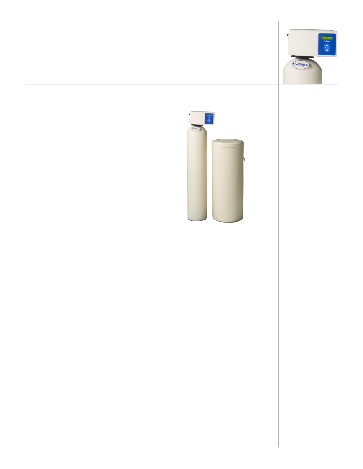
Your Culligan water conditioner consists of three basic components, (A) the Control Valve, (B) the Mineral
Tank, and (C) the Brine System.
A. Control Valve
The exclusive Culligan control valve automatically
A
performs a variety of tasks that are necessary for the
proper operation of your water conditioner. These tasks,
commonly referred to as cycles or operating positions,
B
C
are Service, Regeneration, and Brine Refill.
1. Service: While the control valve is in the
service cycle, hard water is directed down
through the column of Cullex® resin where
hardness minerals are removed from the
water. The softened water is then directed into
your household plumbing lines. The ability of
the Cullex resin to remove hardness minerals
needs to be periodically replenished; this is
referred to as …
2. Regeneration: While the control valve is in
the regeneration cycle, water is first directed
up through the column of Cullex resin to flush accumulated sediment out of the resin and down
the drain. Then, the regenerant brine solution is slowly drawn from the bottom of the salt storage
tank of the Brine System and is directed down through the column of Cullex resin, restoring the
ability of the resin to remove hardness minerals from your water supply. Once completed, the
regeneration cycle is followed by …
3. Brine Refill: While the control valve is in the brine refill cycle, a predetermined amount of
water is directed to the salt storage tank of the Brine System so that additional salt can be dissolved to provide the brine solution that will be needed for the next regeneration cycle.
The Culligan
Process
B. The Mineral Tank
The Mineral Tank contains the Cullex resin column, Cullsan® underbedding, and an outlet manifold (the
Culligan Municipal also includes carbon media for chlorine taste & odor reduction). The number of gallons
of hard water that can be softened by the Cullex resin column before it needs regeneration is called the
“capacity” of the resin column, and depends upon the amount of hardness minerals in each gallon of
water (expressed as grains per gallon) and upon the amount of regenerant brine solution (expressed as
pounds of salt) passed through the resin column during regeneration.
Your Culligan service person, taking into account the hardness of your water and the amount of softened
water your household may reasonably expect to use each day, has carefully established how often the
softener will regenerate and how much salt will be used for each regeneration. This will ensure that all of
your soft water needs will be fulfilled without using an excessive amount of salt.
C. The Brine System
The Brine System consists of a salt storage container and hydraulic Dubl-Safe™ valve. The salt storage container holds the salt that is used to make the regenerant brine solution. The hydraulic Dubl-Safe valve limits
the amount of water that is returned to the salt storage tank during the brine refill cycle.
Because a predetermined amount of salt is dissolved with each brine refill cycle, the salt must be periodically replenished in order to maintain efficient operation. Your Culligan service person will be able to tell
you about how often salt must be added to the salt storage container.
01021076
7
Modes of
Operation
Water Meter Mode
In water meter mode, the controller keeps track of the quantity of water that has flowed through the resin
bed. Based on the influent water hardness and the hardness capacity of the resin bed, a service life expectancy in the quantity of softened water is calculated and programmed into the control. When the set point
is reached, regeneration is triggered. If the predict mode is not selected the regeneration will start at time
of regeneration. In immediate mode the regeneration starts as soon as the regeneration signal is provided.
If time clock backup is set and the capacity has not been exhausted but the days since last regen is greater
than time clock backup, setting the softener will immediately regenerate.
Aqua-Sensor® Mode
The Aqua-Sensor is a conductivity probe that senses when the hardness front passes through the resin
bed. It functions independently of the influent water hardness so therefore, is useful in conditions when the
influent water hardness varies throughout the year. It provides for the most efficient mode of operation. In
addition to sensing when a resin bed is exhausted, it can also be used to determine when the brine solution is rinsed from the resin bed during the Brine Draw/Slow Rinse cycle triggering the control to move to
fast rinse. This patented feature provides water savings by optimizing the amount of rinse water required
to completely rinse out the resin bed.
Smart Brine Tank Probe
The smart brine tank probe monitors conditions inside the brine tank. It predicts when salt needs to be
added to the brine tank, detects the presence of salt-bridging, eductor line plugging and brine tank overfilling.
Wireless Remote Control
The wireless remote control displays the current status of the water softener or filters and allows for remote
control. It can be located up to 200 feet away from the softener (depending upon building construction
materials). The wireless remote displays information about softener performance, problems, days of salt
remaining and allows remote control for regeneration.
The wireless remote control is designed to communicate at 915 MHz and to work without interference with
other 915 MHz devices such as cordless telephones and baby monitors.
Modem
The modem allows for the system to be remotely monitored detecting problems before they occur, to schedule salt delivery when it is needed and to keep the system software up to date with the latest advances.
Manual Regeneration
Manual regeneration can be initiated via the softener control valve or wireless remote display. Manual
regeneration can be initiated to begin regeneration immediately or that night. To immediately initiate re-
generation, press and hold for at least ten (10) seconds. To cancel a delayed regeneration, press and
hold for at least five (5) seconds.
Predict Mode
The Predict Mode is used with the flow meter to determine the optimum regeneration point. Before the regeneration starts, the control will compare the remaining capacity value with the average daily water use.
If the average daily water usage is less than the reserve capacity, the controller will wait 24 more hours
before regeneration. If the reserve capacity is less than the average daily water usage, the control will
initiate regeneration. This works in delay mode only. At any time, if the total capacity value is reached,
the control will initiate an immediate regeneration.
Pre-Rinse Mode
The Pre-rinse mode is used to pre-rinse the softener resin bed or filter media. The pre-rinse in flow meter
mode will occur after the control has sensed that no water has flowed through the control for a period of X
hours (can be set through the programming menu). When the control is in this mode, once the X amount
8
01021076

of hours have elapsed the control will cycle to the fast rinse position for the pre-set length of minutes and
then return to the home or service position.
Down Flow Regeneration
Water and regenerate flow downward through the media tank.
Up Flow Regeneration
Water flow is downward and regenerate flow is upward through the media tank. The significance of this
is that regeneration will be most effective in those parts of the resin bed which are treated with the freshest
regenerate solution. There will tend to be less hardness leakage with up-flow regeneration.
Proportional Brining
The control monitors your softened water usage making only enough brine to regenerate that part of the
resin bed that has been exhausted. In this way the amount of salt used relates directly to the amount of
softened water used, making it more efficient and cost effective. Proportional brining can only be used
with upflow regeneration. The Aqua-Sensor or meter can be used to initiate a regeneration.
Dial-A-Softness
®
Dial-A-Softness is a manual adjustment built into the control valve that allows for variable hardness bypass
into the softened water. The hard water bypass can be adjusted from 0% to 30%. The Dial-A-Softness also
increases the softener capacity in proportion to the percent hard water bypass (less salt used).
01021076
9
Installation
NOTE Read this section entirely before starting the installation. Follow all applicable
plumbing and electrical codes.
Component Description
The water conditioner is shipped from the factory in a minimum of three cartons. With the exception of
media containers, remove all components from their cartons and inspect them before starting installation.
Control Valve Assembly
Includes the control valve, bypass valve, and meter. Small parts packages will contain additional installation hardware, and the conditioner Owner’s Guide.
Media Tank
Includes Quadra-Hull™ media tank complete with Cullex® ion exchange resin, underbedding and outlet
manifold (12” and 14” tanks are shipped without media).
Salt Storage Tank Assembly
Includes salt storage container with support plate and Dubl-Safe™ brine refill valve and chamber.
Tools and Materials
The following tools and supplies will be needed, depending on installation method.
NOTE Check and comply with your state and local codes. You must follow these
guidelines.
For installations in Massachusetts, Massachusetts Plumbing Code 248 CMR
shall be adhered to. Consult your licensed plumber for installation of this
system. This system and its installation must comply with state and local
regulations. The use of saddle valves is not permitted.
10
All Installations
• Safety glasses
• Phillips screwdrivers, small and medium tip.
• Gauge assembly
• Silicone lubricant (P/N 00471507 or equivalent)—Do Not Use Petroleum-Based Lubricants
• A bucket, preferably light-colored
• Towels
Special Tools
• Torch, solder and flux for sweat copper connections
• Use only lead-free solder and flux for all sweat-solder connections as required by state and federal
codes.
• Threading tools, pipe wrenches and thread sealer for threaded connections.
• Saw, solvent and cement for plastic pipe connections.
01021076
Materials
• Brine line, 3/8” (P/N 01009819 or equivalent)
• Drain line, 1/2” (P/N 00303082, gray, semi-flexible; P/N 00331946, black, semi-rigid; or
equivalent)
• Thread sealing tape
• Pressure reducing valve (if pressure exceeds 125 psi [860 kPa])
• Pipe and fittings suited to the type of installation
• Water softener salt (rock, solar or pellet salt formulated specifically for water softeners)
Application
Water Quality
Verify that raw water hardness and iron are within limits. Note the hardness for setting the salt dosage
and recharge frequency.
Iron is a common water problem. The chemical/physical nature of iron found in natural water supplies is
exhibited in four general types: Dissolved Iron, Particulate Iron, Organic Bound Iron and Bacterial Iron.
Hardness sample kits are available through your local Culligan dealer.
Pressure
If pressure exceeds 125 psi (860 kPa), install a pressure reducing valve (see materials checklist). On private water systems, make sure the minimum pressure (the pressure at which the pump starts) is greater than
20 psi (140 kPa). Adjust the pressure switch if necessary.
CAUTION! Do not use where the water is microbiologically unsafe or with
water of unknown quality adequate disinfection before or
after the unit.
CAUTION! The use of a pressure reducing valve may limit the flow of
water in the household.
Temperature
Do not install the unit where it might freeze, or next to a water heater or furnace or in direct sunlight.
Outdoor installation is not recommended, and voids the warranty. Use the Culligan Outdoor HE softener
for outdoor installations. The Culligan Outdoor HE softener has been certified by Underwriter’s Laboratories for outdoor installation. If installing in an outside location, you must take the steps necessary to assure
the softener installation plumbing, wiring, etc. Areas well protected from the elements (sunlight, rain, wind,
heat, cold), contamination, vandalism, etc. as when installed indoors.
Location
Space Requirements
Allow 6–12 inches (15–30 cm) behind the unit for plumbing and drain lines and 4 feet (1.3 meters) above
for service access and filling the salt container.
Floor Surface
Choose an area with solid, level floor free of bumps or irregularities. Bumps, cracks, stones and other
irregularities can cause the salt storage tank bottom to crack when filled with salt and water.
01021076
11
Drain Facilities
Choose a nearby drain that can handle the rated drain flow (floor drain, sink or stand pipe). Refer to Ta-
ble 3 “Height of Discharge Above Floor Level Operating.” on page 21, for maximum drain line length.
NOTE Most codes require an anti-siphon device or air gap. Observe all local
plumbing codes and drain restrictions. The system and installation must
comply with all state and local laws and regulations.
Electrical Facilities
A 10-foot cord and wall mount plug-in transformer are provided. The customer should provide a receptacle, preferably one not controlled by a switch that can be turned off accidentally. Observe local electrical
codes.
NOTE The softener works on 24 Volt/60 Hz electrical power only. Be sure to use the
included transformer. Be sure the electrical outlet and transformer are in an
inside location to protect from moisture. Properly ground to conform with all
governing codes and ordinances. Observe all local plumbing codes and drain
restrictions. The system and installation must comply with all state and local
laws and regulations.
NOTE P/N 01020620 and P/N 01018133 plug-in transformer are rated for indoor
installations only.
Placement
NOTE Read this section entirely before starting the installation. Follow all applicable
plumbing and electrical codes.
Refer to Figure 1 for system placement.
1. With the exception of media containers, open the remaining containers, remove all the components, and inspect them before starting installation.
2. Set the media tank on a solid, level surface near water, drain and electrical facilities.
3. Set the brine system on a flat, smooth, solid surface as near the media tank as possible.
Tank Assembly
9” and 10” tanks are filled with media at the factory.
1. Before the unit can be connected to the plumbing, you must insert the manifold and load the
media into the tank for 12" and 14" units.
12
01021076
CAUTION! Do not lay the tank down unless a suitable lifting device
is available. Personal injury and damage to the unit can
result if dropped.
Position the Mineral Tank(s)
Treated Water Out
Determine the location for the mineral tanks(s) prior to loading, because they will be difficult to move after
the underbedding and gravel are loaded.
To
Hose
Drain Line
Hard Water In
Heater
Bibs
Air Gap
(2x Pipe Diameter
or 1 inch, whichever
is larger)
Figure 1. HE system placement.
Load the Tank (12" and 14" Tanks)
1. Position the tank so that the Culligan® logo is in the front.
2. Remove the inlet strainer.
3. Install the outlet manifold into the tank (Figure 2).
4. Cover the tops of the manifolds with a clean rag.
5. Using a large-mouth funnel, load the Culligan underbedding
through the top of the tank.
CAUTION! DO NOT allow the outlet manifold
to move when loading the media.
The manifold must remain vertical
to ensure a good seal at the gasket.
Rap the tank near the bottom with a
rubber mallet to level the sand.
Brine Tank
Water
Meter
or
Pump
6. Load the tank with the Cullex® ion exchange resin. Leveling is not
required.
7. Remove the funnel.
8. Install the inlet strainer making sure to thread the strainer until it
bottoms out on the tank thread. Failure to install the strainer correctly can cause the control to leak.
Figure 2. HE Softener tank.
01021076
13
Install Aqua-Sensor
1. Measure the sensor cable length as shown in dimension Y. See Figure 2 and Table 1 (the AquaSensor cord is set at the factory for a 9" tank).
Tank Model Dimension Y
9" Quadra-Hull™ Tank 40"
10" Quadra-Hull Tank 44"
12" Quadra-Hull Tank 42"
14" Quadra-Hull Tank 52"
Table 1. HE cable lengths.
2. Loosen the small Aqua-Sensor Plug; a needle-nose pliers works
best. See Figure 3.
3. Moisten the cable sheath and slide the cable grip up or down to
the proper cable length.
4. Tighten the small Aqua-Sensor plug so that the fitting cannot slide
along the cable.
NOTE There must be no kinks or bends in the cable.
5. Insert the probe and cable through the Aqua-Sensor port.
6. Tighten the Aqua-Sensor plug into the Aqua-Sensor port.
Figure 3. Aqua-Sensor plug.
NOTE The media tank must be backwashed so that the Aqua-Sensor probe can
fall into the proper position. See “Recommended Aqua-Sensor® Start-Up
Procedure” on page 39.
Small
Aqua-Sensor
Plug
®
14
01021076
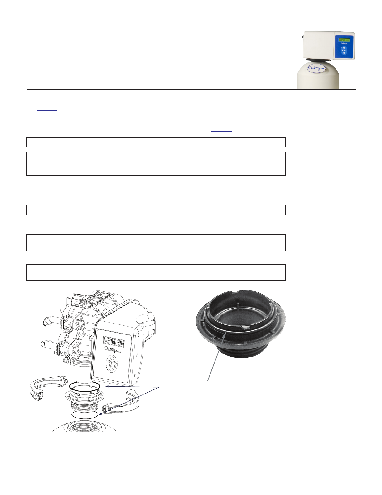
Mount the Control Valve
See Figure 4 for an illustration on mounting the control valve to the tank.
1. Assemble the O-rings, located in the parts pack, to the tank adapter.
2. The valve adapter O-ring sits on the first step on the adapter. See Figure 5.
NOTE Do not push the top O-ring down to the flange surface on the adapter.
NOTE The larger of the two O-rings in the parts should be positioned between the
adapter and the valve. Do not stretch the smaller O-ring onto the top of the
tank adapter.
3. Lubricate only the top o-ring on the tank adapter and the outlet manifold O-ring with silicone
lubricant.
4. Screw the adapter into the tank until the adapter bottoms out on the tank flange.
NOTE The adapter only needs to be tightened hand-tight to the tank flange.
5. Align the manifold with the center opening in the valve, and firmly press the valve onto the
adapter.
NOTE Make sure to push the valve straight down onto the manifold. If the valve is
cocked, it may cause the O-ring to slip off the manifold.
6. Assemble the tank clamp to the control, and tighten the clamp screw.
NOTE The clamp and valve will be able to rotate on the tank until pressure is
applied.
Figure 4. Mounting the control valve.
Add O-Rings
O-Ring
Figure 5. Valve adapter O-ring.
01021076
15
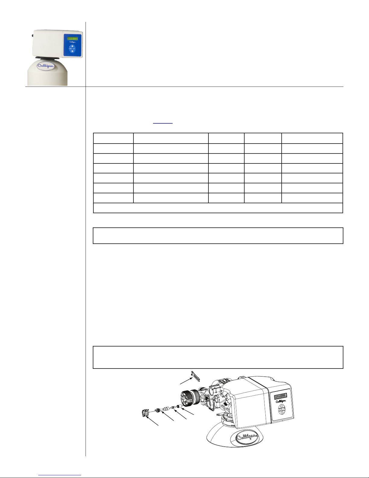
Backwash Flow Control, Eductor Nozzle—Throat
Use the recommended backwash flow control, eductor nozzle, and eductor throat for various size tanks.
See Table 2.
Refer to Figure 6 through Figure 9 and instructions below for changing the backwash flow control, eductor
nozzle, and eductor throat.
Unit Backwash Flow Nozzle Throat Brine Refill Flow
9" Upflow 2.5–3.1 gpm (#2 Brown)* Blue* Gray* 0.45 gpm
10" Upflow 2.5–3.1 gpm (#2 Brown)* Blue White 0.45 gpm
9" Downflow 2.5–3.1 gpm (#2 Brown)* Blue* Light Brown* 0.45 gpm
10" Downflow 2.5–3.1 gpm (#2 Brown)* Beige Light Brown 0.45 gpm
12" Downflow 3.0–3.2 gpm (#3 Green) Beige Light Brown 0.8 gpm
14" Downflow 5.3 gpm (Black) Green Blue 0.8 gpm
* Shipped assembled inside the control standard from factory
Table 2. Flow Restrictors.
NOTE For upflow models, the backwash and fast rinse default times are set at five
(5) minutes.
Eductor Nozzle and Throat Replacement
Refer to Figure 6 and the instructions below when changing the eductor nozzle and throat.
1. Remove the eductor cap clip.
2. Remove the eductor cap.
3. Remove the eductor assembly.
4. Remove the eductor screen from the assembly
5. Remove the blue nozzle and replace it with the correct nozzle. See Table 2.
6. Make sure to put the O-ring on the nozzle.
7. Replace the eductor throat if required.
8. Reverse the procedure to reassemble.
NOTE Observe the orientation of the arrow on the eductor cap. The arrow faces
down for downflow regeneration applications; the arrow faces up for
upflow/proportional brining regeneration applications.
16
01021076
Clip
Screen
Throat
Eductor Cap
Nozzle
Figure 6. Removing the eductor nozzle and throat.
Backwash Flow Control Replacement
Refer to Figure 7 through Figure 9, Table 2, and instructions below to replace the backwash flow control.
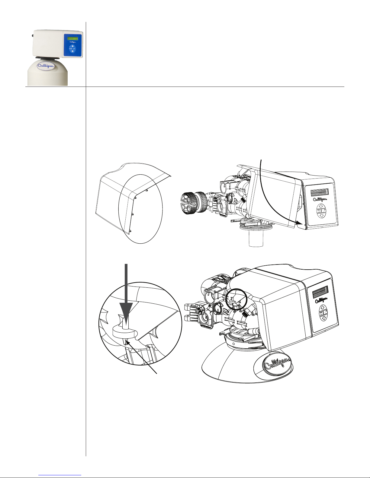
1. Remove the cover by releasing the cover fastener from the control valve. See Figure 7 and
Figure 8.
2. Remove the drain clip and pull the drain elbow straight off. See Figure 9.
3. Remove the backwash flow control located behind the elbow.
4. Install the correct backwash flow control. See Table 2.
5. Reverse the procedure to reassemble.
NOTE The number on the flow control should face into the valve body.
NOTE Do not re-install the cover until the drain line tubing is connected.
A
Figure 7. HE softener cover fastener clip. Figure 8. Removing the HE softener cover.
Brine Elbow
Drain Elbow
Filter
Flow Control
Clips
Figure 9. Removing the drain elbow and brine elbow.
01021076
17
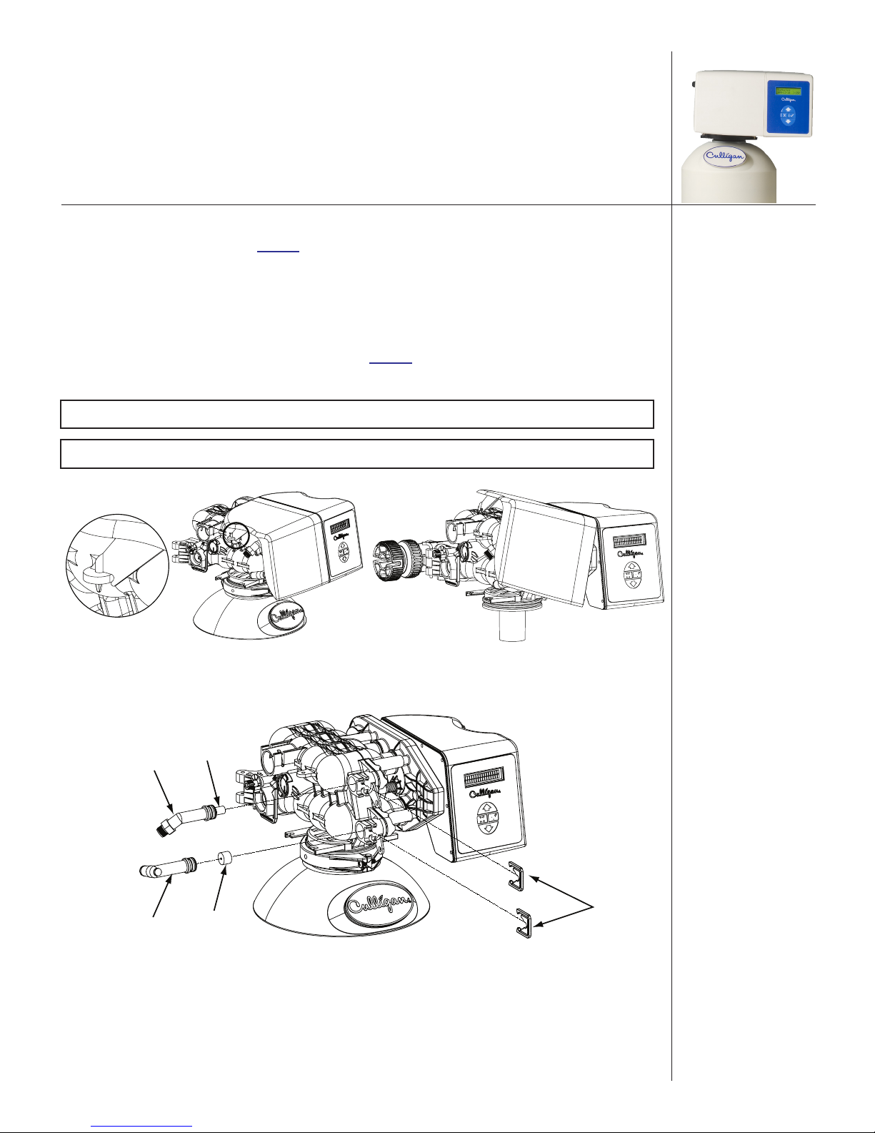
Attaching the Cover
Fastener
Push down
Once the drain and brine line is connected, re-attach the cover.
1. Insert the two pins on the top of the cover into the two holes on top of the frame; the cover
should be slightly angled. See Figure 10.
2. Rotate the cover downward inserting the two pins on the side of the cover into the two holes on
side of the frame. See Figure 11.
3. Attach the cover fastener onto the control valve. See Figure 12.
Figure 10. Cover fastener clip. Figure 11. Reattaching the HE softener cover.
into place
A
Cover
Figure 12. Reattaching the cover fastener.
18
01021076
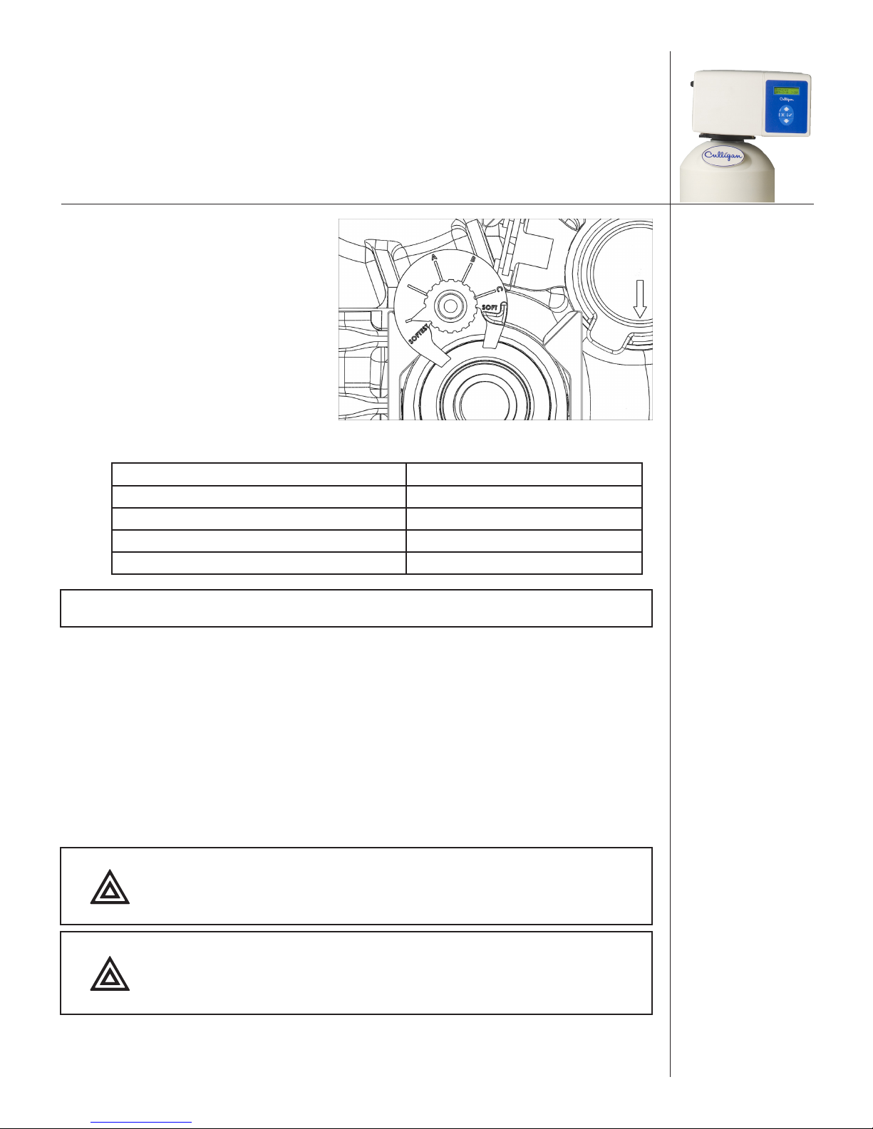
Dial-a-Softness
Dial-a-Softness is a manual adjustment built into
the control valve that allows for variable hardness
bypass into the softened water. The hard water
bypass can be adjusted to produce 1–3 gpg
hardness bleed. Shipped from the factory the Dial-a-Softness knob is set to the “SOFTEST” position
(no hard water bypass). See Figure 13.
To set the Dial-a-Softness:
1. Locate the Dial-a-Softness knob on the
control valve.
2. Set the Dial-a-Softness knob to position
A, B, or C as outlined in the table
below, based on raw water hardness; this should produce a 1–3 gpg hardness bleed.
Figure 13. Dial-a-Softness knob.
Letter on Dial-a-Softness Knob 1–3 gpg Hardness Bleed
SOFTEST 0
A Greater than 20 gpg
B Between 10–20 gpg
C Less than 10 gpg
NOTE The HE must take into account the adjusted capacity if the Dial-a-Softness was
changed. See Advanced System Setup to update the Dial-a-Softness setting.
Plumbing Connections
Shipped with each softener is a Culligan® bypass valve, which is used to connect the softener to the
plumbing system. The bypass allows the softener to be isolated from the water service line if service is
necessary while still providing water to the home. The bypass valve can be directly plumbed into the
system, or can be connected with the following optional sweat connection kits.
• P/N 01010783 1" Sweat Copper Adapter Kit
• P/N 01016564 3/4" Sweat Copper Adapter Kit
• P/N 01016565 3/4" Elbow Sweat Copper Adapter Kit
• P/N P1018757 1" NPT Plastic Elbow Adapter Kit
• P/N P1018758 1" NPT Plastic Installation Kit
CAUTION! Close the inlet supply line and relieve the system
pressure before cutting into the plumbing! Flooding
could result if not done!
CAUTION! When making sweat connections, use care to keep heat
away from the plastic nuts used to connect the plumbing
to the bypass. Damage to these components might result
otherwise.
01021076
19
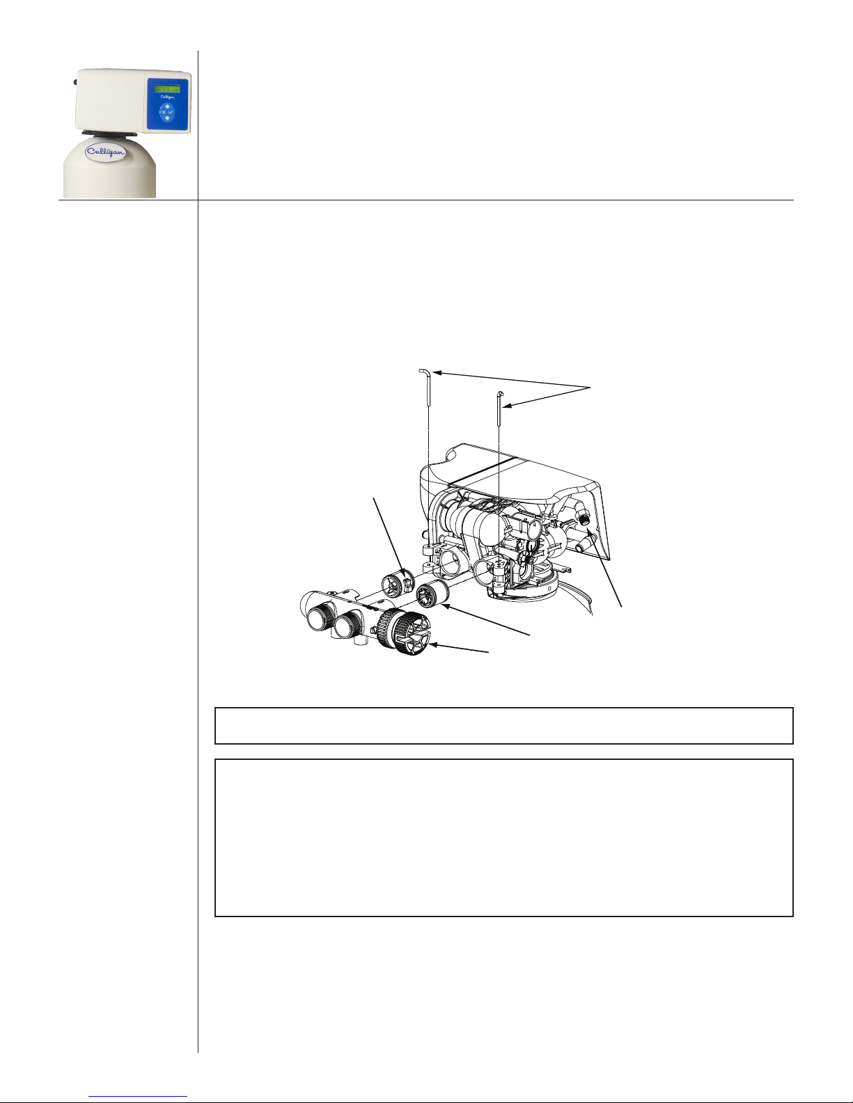
Bypass Valve Installation
Refer to Figure 14 and the instructions below to connect the meter, bypass valve, and interconnecting
pipe.
1. All HE units are equipped with a Soft-Minder® meter. The meter is installed on the outlet side
of the control valve. The meter body fits in the same space as the coupling between the control
valve and the bypass. Make sure the arrow on the flow meter is pointing in the direction of the
flow.
2. The bypass valve connects directly to the control valve with the meter and coupling and two
assembly pins. Lubricate all O-rings on the couplings/meter with silicone lubricant.
Assembly Pin
Coupling
Brine Connection
Meter Body
Bypass
NOTE The new Low Flow Meter has a white dot on the connection for the wire
harness.
NOTE If the ground from the electrical panel or breaker box to the water meter or
underground copper pipe is tied to the copper water lines and these lines
are cut during installation of the bypass valve, an approved grounding strap
must be used between the two lines that have been cut in order to maintain
continuity. The length of the grounding strap will depend upon the number
of units being installed. In all cases where metal pipe was originally used
and is later interrupted by the bypass valve to maintain proper metallic pipe
bonding, an approved ground clamp c/w not less than #6 copper conductor
must be used for continuity. Check your local electrical code for the correct
clamp and cable size.
20
01021076
Figure 14. Bypass valve assembly.
Drain Line Connection
Refer to Table 3 for drain line length and height limitations under the applicable tank size.
1. Remove 1/2” pipe clamp from the small parts pack included with the control.
2. Route a length of 1/2” drain line from the drain elbow to the drain.
3. Fasten the drain line to the elbow with the clamp.
4. Secure the drain line to prevent its movement during regeneration. When discharging into a
sink, or open floor drain, a loop in the end of the tube will keep it filled with water and will
reduce splashing at the beginning of each regeneration.
NOTE Waste connections or drain outlets shall be designed and constructed to
provide for connection to the sanitary waste system through an air gap of
two pipe diameters or 1 inch, whichever is larger.
NOTE Note: Observe all plumbing codes. Most codes require an anti-siphon device
or air gap at the discharge point. The system and installation must comply
with state and local laws and regulations.
Operating
Pressure
30 psi (210 kPa) 60 ft (18 m) 50 ft (15 m) 30 ft (9 m) 15 ft (5 m) Not allowable Not allowable
40 psi (279 kPa) 100 ft (30 m) 90 ft (27 m) 70 ft (21 m) 50 ft (15 m) 30 ft (9 m) 12 ft (4 m)
50 psi (349 kPa) 145 ft (41 m) 115 ft (35 m) 80 ft (24 m) 80 ft (24 m) 60 ft (18 m) 40 ft (12 m)
60 psi (419 kPa) 100 ft (30 m) 100 ft (30 m) 85 ft (26 m) 60 ft (18 m)
80 psi (559 kPa) Normal installation should not require 140 ft (43 m) 120 ft (37 m)
100 psi (699 kPa) more than 100 ft (30 m) of drain line 150 ft (46 m)
0 ft (0 m) 2 ft (0.6 m) 4 ft (1.2 m) 6 ft (1.8 m) 8 ft (2.4 m) 10 ft (3 m)
Table 3. Height of Discharge Above Floor Level Operating.
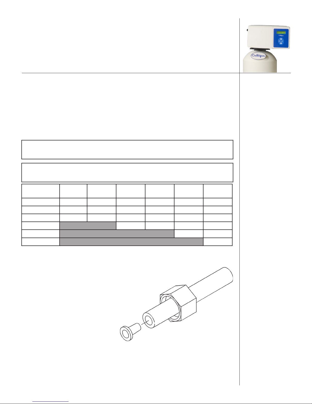
Connect the Brine Line
1. Measure a length of brine line sufficient to reach from the brine tank
to the brine fitting, with no sharp
bends. For easier access to the float
it is recommended to add an extra
four feet (1.3 meters) of length to the
brine line.
2. Cut both ends of the brine line
squarely and cleanly.
3. Slip the white nut over one end of
the tubing and press the plastic insert
into the end of the tubing (Figure
15). Connect to the brine valve and
Figure 15. Brine valve tubing.
tighten nut.
4. Remove white nut and plastic insert from the small parts pack.
5. Slip the white nut over one end of the tubing and press the plastic insert into the end of the tubing (Figure 15). Connect to the brine connection on the valve and tighten nut.
01021076
21
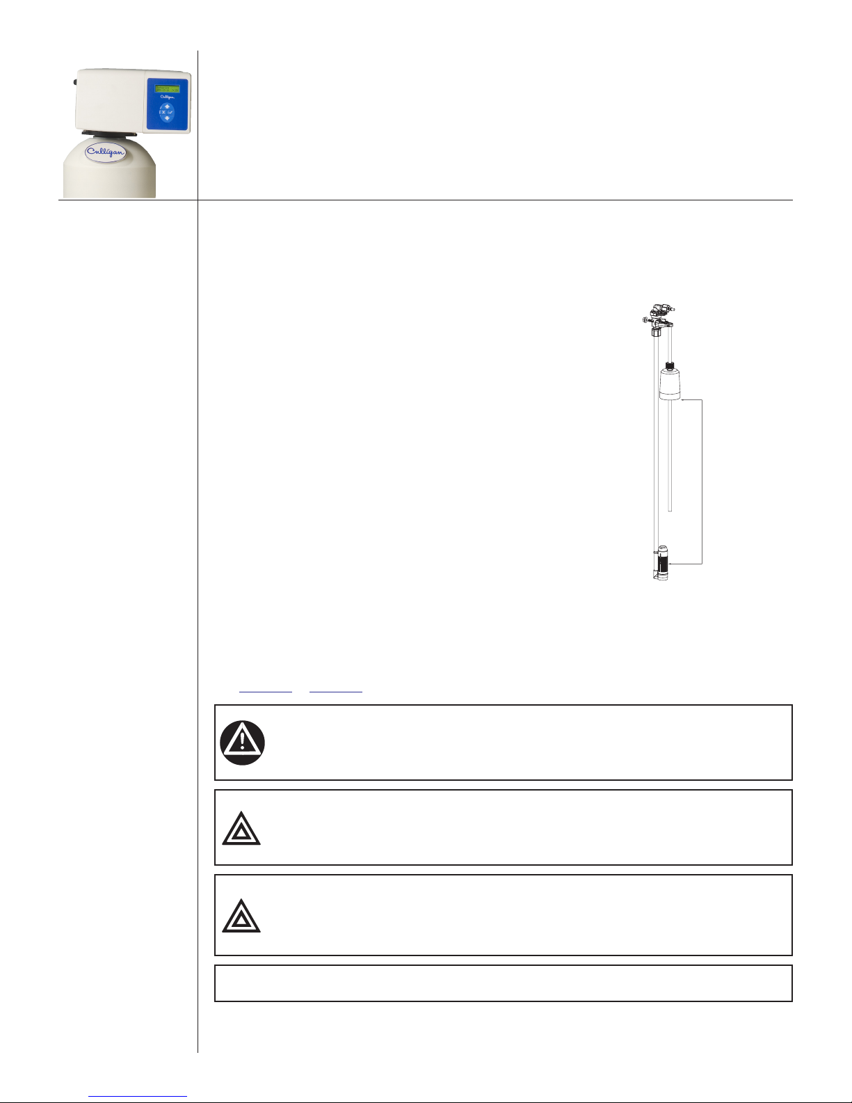
Fill The Salt Storage Container
Fill the salt storage container with water until the level reaches about 1 inch above the salt support plate.
Pour salt into the container. Fill with salt to within a few inches of the top.
Brine Valve “A” Dimension
The brine valve contains a brine float which can serve as
a backup refill shutoff in the event of a failure, such as a
power outage when in the refill position. The float level
should be set based on the salt dosage setting. Refer to
Figure 16.
1. Remove nut retaining brine valve to brine chamber.
2. Lift the brine valve from the brine chamber.
3. Find the correct “A” dimension in the HE
Softener Installation/Operation manual (PN
01021606).
4. Set the distance from the top of the filter screen
to the base of the float accordingly. The slight
difference in height when the float is pulled up
or down is negligible.
5. Re-install into brine chamber and replace nut.
Figure 16. Brine valve “A” dimension.
“A” Dimension
Circuit Board Connections
The 24 Volt power supply and flow meter wire harness is already connected to the circuit board. If no
other circuit board connections are required proceed to the First Time Setup. Refer to the instructions below
and Figure 17 to Figure 20 for connecting the Aqua-Sensor probe wire harness to the circuit board.
WARNING! Disconnect all electrical power to the unit before connecting.
CAUTION! Grip all connections to the circuit board by the connecting
terminals for assembly and disassembly. Failure to do so could
result in damage to the wire leads or connecting terminals.
CAUTION! Do not touch any surfaces of the circuit board. Electrical static
discharges might cause damage to the board. Handle the
circuit board by holding only the edges of the circuit board.
Mishandling of the circuit board will void the warranty.
NOTE Observe all state and local electrical codes.
22
01021076
 Loading...