

Page 1

Hydrostatic Zero-Turn
Residential Riding Mower
Turf Equipment
MODEL
20HP Z-Force 44
23HP Z-Force 50
OPERATOR’S AND SERVICE MANUAL
Page 2

TABLE OF CONTENTS
Foreword. . . . . . . . . . . . . . . . . . . . . . . . . . . . . . . . . . . . . . . . . . . . . . . . . . . . . . . . . . . . . . . 3
General Safety Operations. . . . . . . . . . . . . . . . . . . . . . . . . . . . . . . . . . . . . . . . . . . . . . . . . 4
A.General Operation . . . . . . . . . . . . . . . . . . . . . . . . . . . . . . . . . . . . . . . . . . . . . . . . . 4
B.Slope Operation . . . . . . . . . . . . . . . . . . . . . . . . . . . . . . . . . . . . . . . . . . . . . . . . . . . 5
C.Children . . . . . . . . . . . . . . . . . . . . . . . . . . . . . . . . . . . . . . . . . . . . . . . . . . . . . . . . .5
D.Service . . . . . . . . . . . . . . . . . . . . . . . . . . . . . . . . . . . . . . . . . . . . . . . . . . . . . . . . . . 6
Safety Decals . . . . . . . . . . . . . . . . . . . . . . . . . . . . . . . . . . . . . . . . . . . . . . . . . . . . . . . . . . . 7
Specifications . . . . . . . . . . . . . . . . . . . . . . . . . . . . . . . . . . . . . . . . . . . . . . . . . . . . . . . . . . . 8
Operating Instructions . . . . . . . . . . . . . . . . . . . . . . . . . . . . . . . . . . . . . . . . . . . . . . . . . . . . 9
A.General. . . . . . . . . . . . . . . . . . . . . . . . . . . . . . . . . . . . . . . . . . . . . . . . . . . . . . . . . .9
B.Controls . . . . . . . . . . . . . . . . . . . . . . . . . . . . . . . . . . . . . . . . . . . . . . . . . . . . . . . . 10
C.Initial Adjustments . . . . . . . . . . . . . . . . . . . . . . . . . . . . . . . . . . . . . . . . . . . . . . . . 12
D.Zero Turn Break-In and Operating Procedures. . . . . . . . . . . . . . . . . . . . . . . . . . . 13
Maintenance and Service. . . . . . . . . . . . . . . . . . . . . . . . . . . . . . . . . . . . . . . . . . . . . . . . .1 5
A.Cl eaning your Deck . . . . . . . . . . . . . . . . . . . . . . . . . . . . . . . . . . . . . . . . . . . . . . . 15
B.Mower Deck . . . . . . . . . . . . . . . . . . . . . . . . . . . . . . . . . . . . . . . . . . . . . . . . . . . . . 16
C.Hydrostatic Dr ive System. . . . . . . . . . . . . . . . . . . . . . . . . . . . . . . . . . . . . . . . . . . 17
D.Electrical Circuit . . . . . . . . . . . . . . . . . . . . . . . . . . . . . . . . . . . . . . . . . . . . . . . . . . 18
E.Tires . . . . . . . . . . . . . . . . . . . . . . . . . . . . . . . . . . . . . . . . . . . . . . . . . . . . . . . . . . .20
F. Brakes. . . . . . . . . . . . . . . . . . . . . . . . . . . . . . . . . . . . . . . . . . . . . . . . . . . . . . . . . . 20
G.
Hydraulic System. . . . . . . . . . . . . . . . . . . . . . . . . . . . . . . . . . . . . . . . . . . . . . . . . 21
H.Storage. . . . . . . . . . . . . . . . . . . . . . . . . . . . . . . . . . . . . . . . . . . . . . . . . . . . . . . . .21
Maintenance Schedule. . . . . . . . . . . . . . . . . . . . . . . . . . . . . . . . . . . . . . . . . . . . . . . . . . . 22
Performance Adjustments . . . . . . . . . . . . . . . . . . . . . . . . . . . . . . . . . . . . . . . . . . . . . . . . 24
A.High Speed Tracking Adjustment . . . . . . . . . . . . . . . . . . . . . . . . . . . . . . . . . . . . . 24
B.Engine RPM Check and Adjustment . . . . . . . . . . . . . . . . . . . . . . . . . . . . . . . . . . 24
C.Deck Corner Ball Wheel Roller Settings. . . . . . . . . . . . . . . . . . . . . . . . . . . . . . . . 25
D.Deck Center Anti-Scalp Roller Settings . . . . . . . . . . . . . . . . . . . . . . . . . . . . . . . .25
E. Lap Bar Adjustment . . . . . . . . . . . . . . . . . . . . . . . . . . . . . . . . . . . . . . . . . . . . . . . 25
F. Deck Leveling Procedure . . . . . . . . . . . . . . . . . . . . . . . . . . . . . . . . . . . . . . . . . . . 25
Wiring Diagram. . . . . . . . . . . . . . . . . . . . . . . . . . . . . . . . . . . . . . . . . . . . . . . . . . . . . . . . . 27
Slope Gauge. . . . . . . . . . . . . . . . . . . . . . . . . . . . . . . . . . . . . . . . . . . . . . . . . . . . . . . . . . .28
Warranty. . . . . . . . . . . . . . . . . . . . . . . . . . . . . . . . . . . . . . . . . . . . . . . . . . . . . . . Back cover
This product may be covered by one or more of the following patents:
D409,208; 5,946,894; 6,070,690; Pending
2
Page 3

FORWARD
The Hy d ros ta tic Z e ro- Tu rn Rid in g Mo wer pro v ide s su per b m an eu verab ility a nd mid - m o u nt cu tting. The mac hine i ncor pora tes many safety featur es that shoul d be st udied by al l operators
before use. The list of safety precautions should receive particular attention.
This manual presents all of the operating and maintenance ins truc tions necessar y to keep
your mower at peak efficiency. If operated and maintained properly, your mower will give
dependable service.
CAUTION:
Only thoroughly trai ned persons should operate and maintain this
mower. This machine can cause serious injur y to anyone who misuses it and does not understand its operation. For their personal
safety, all operators ar e required to read this entire manual before
operating the mower.
Hazard control and accident prevention are partially dependent
upon the design and configuration of the equipment. Awareness,
concern, prudence and proper training of the personnel involved in
the operation, transport, maintenance and storage of the equipment, are essential for hazard control and accident prevention.
NOTE:
The engine manufacturer is responsible for all engine-related issues with
regards to performance, power-rating, specifications, warranty and service.
Please refer to the engine manufacturer’s owner’s/operator’s manual,
packed seperately with your unit, for more information.
3
Page 4

WARNING
• The engine exhaust, some of its constituents, and certain vehicle components contain or emit chemicals
known to the St ate of California to cause cancer, birth defects or other reproductive harm .
• This unit is equipped with an internal combustion engine and should not be used on or near any unimproved
forest-covered, brush-covered, or grass-covered land unless the engine’s exhaust system is equipped with a
spark arrester meeting applicable local or state laws (if any). If a spark arrester is used, it should be maintaine d in eff ective work i ng or der by the op e r a to r.
• In the State of California, the above is required by law (Section 4442 of the California Public Resources
Code). Other States may have similar laws. Federal laws apply to federal lands. A spark arrester muffler
may be available.
IMPORTANT
THIS SYMB OL POINTS OU T IMPO RTANT SAFET Y INSTRUCTIONS WHICH, IF NOT FOLLOWED,
COULD ENDANGER THE PERSONAL SAFETY AND/OR PROPERTY OF YOURSELF AND OTHERS. READ AND FOLLOW ALL INSTRUCTIONS IN THIS MANUAL BEFORE ATTEMPTING TO
OPERATE YOUR UNIT. FAILURE TO COMPLY WITH THESE INSTRUCTIONS MAY RESULT IN
PERSON AL INJURY. W HEN YO U SEE TH IS SYMBOL-
D ANGER
Your lawn mower was built to be operated according to the rules for safe operation
in this manual. As with any type of power equipment, carelessness or error on the
part of the operator can result in injury. This lawn mower is capable of amputating
hands and feet or throwing objects. Failure to observe the following safety instructions could re sult in serious injury or death.
GENERAL SAFETY
OPERATIONS
A. GENERAL OPERATION
1. Read, un der stan d and f o llo w a ll inst ructio ns in
the man ual and on the machine before starting. Keep this manual in a safe place for
future and regular ref erence and f or ordering
replac em ent parts.
2. Only allow responsible individuals familia r with
the instructions to operate the machine. Know
the controls and how to stop the machine
quickly.
3. Do not put hands or feet under the cutting
deck or near rotating parts.
4. Clear the area of objects such as rocks, toys,
wire, etc. whic h could b e pic ked up an d throw n
by the blades. A small object may ha ve been
overlooked and co ul d be accidentally thrown
by the mo wer in any dire ction and ca use injury
to you or a bystander. To help avo i d a thrown
objects injury, keep children, animals,
byst anders and helpers at least 75 feet fro m
the mower while it is in operation. Always
wear sa f et y glass es w ith side shi elds or safety
goggles during operation or while performing
and adjustment or repair, to protect eyes from
foreign objects . Stop the blades when crossing gr avel drives, walks or roads.
SAFE OPERATION PRACTICES
HEED ITS WARNING.
5. Be sure the area is clear of othe r people
before mowing. Stop m achine if anyone
enters the area.
6. Never carry passengers.
7. Disenga ge t he blades bef ore shifting into
reverse and ba ck i ng up. Always look down
and behind before and while backing.
8. Be aware of the mow er and attachme nt di scharge di rec tion an d d o not po int it at an y on e .
Do not operate the mower without either the
entire grass catcher or the chute guard in
place.
9. Slow down before turning. Operate the
machine smoothly. Avoid erratic operation
and excessive speed.
10. Never lea ve a running machine unattended.
Always turn off the blades, place the transmission in neutral, set the parking brake, stop the
engine and remove key before dismounting.
11. Turn off blades when not mowing.
12. Stop the engine and wa i t until the blades
come to a complete stop before (a) removing
the grass catcher or unclogging chute, or (b)
making an y r epa irs, adj ust ing o r remo v ing an y
grass or debris.
13. Mow only in daylight or good artificial light.
14. Do not operate the mac hi ne while under the
influenc e of al cohol or drugs.
15. Watch for traffic w hen operating near or crossing road ways.
16. Use extra care when loading or unloading the
machine i nto a trailer or truck. This unit
4
Page 5

should not be driven up or down a ramp onto
a trailer or t ruck under power, because the
unit co uld tip over ca using seriou s personal
injury. The unit must be pushed m anually on
a ramp to load or unload properly.
17. Never ma ke a cutting height adjus tment while
the engin e is running if the operator must dismount to do so.
18. Wear sturdy, rough-sol ed work shoes and
closefi tti ng slacks and shirts . Do not wear
loose fitting clothes or jewelry. They can be
caught in moving parts. Never operate a unit
in bare feet, sandals or sneakers.
19. Check overhead clearance carefully before
driving under power lines, wires, bri dges or
low h anging tree br anches, before ente rin g or
leaving buildings, or in any other sit uation
where the operator may be struck or pulled
from the unit, which could result in serious
injury.
20. Disengage all attachm ent clutches, set the
parking br ake to the on positi on and put the
lap bars to th e neutral or out posit i on, before
attempting to start the engine.
21. Your mower is designed to cut normal residential g rass of a height no more than 10”.
Do not attem pt to mow through unusual ly tall,
dry grass (e. g. pas ture ) or piles of dry leaves.
Debris ma y build up on the mower dec k or
contact th e engine exhaust presenting a
potential f ire hazard.
22. Use onl y accesso r ies app rov ed for th i s
machine by
and follow all instructions provided with the
appro ved accessory.
Cub Cadet.
Read, understand
B. SLOPE OPERATION
Slopes are a major factor related to loss of control and tip-over accidents, which can result in
DO:
All
slopes require extra
T all grass can hide
severe injur y or death.
caution. If you cannot back up the slope
or if you feel uneasy on it, do not mow it.
For your safety, use the slope gauge included as
a part of this manual (see pg. 27) to measure
slopes before operating this unit on a sloped or
hilly area. If the slope is greater than 15 degrees
as shown on the slope gauge, do not operate this
unit on that area or serious injury could result.
• Mow across slopes, not up and down.
• Remove obstacles such as rocks, limbs, etc.
• Watch for holes , ruts or bumps. Uneven terrain
could overturn the machine.
obstacles.
• Use slow speed. Choose a low enough speed
so that you will not have to stop while on the
slope.
• Follow the manufacture’s recommendat ion s for
counterweights with attachments to improve stability.
• Use extra care with grass catchers or other
attachments. These can change the stability of
the machine.
• Keep all movement on the slopes
gradual.
or direction. Rapid acceleration or deceleration
could cause the front of the machine to lift and
rapidly flip over backwards, which could cause
serious injury.
• Avoid starting or stopping on a slope. If the
tires lose traction, disengage the blades and proceed slowly
Do not
•
turn slowly and use extra care.
• Do not
ments. The mower could suddenly turn over if a
wheel is over the edge of a cliff or ditch, or if an
edge caves in.
Do not
•
could cause sliding.
• Do not
your foot on the ground.
• Do not
Do not make sudden changes in speed
straight
turn on slopes unless necessar y ; then,
mow near drop-offs, ditches or embank-
mow on wet grass. Reduced traction
try to stabilize the machine by putting
use the grass catcher on steep slopes.
down the slope.
DO NOT :
slow
C. CHILDREN
Tragic accidents can occur if the operator is not
alert to the presence of children. Children are
often attracted to the machine and the mowing
activity.
remain where you last saw them.
1. Keep children out of the mowing area
and in wat chf ul care o f a n adul t other t ha n the
operator.
2. Be alert and turn the machine off if children
ente r the area.
3. Befor e and whe n bac k ing up , look beh ind a nd
down
4. Nev er c arry chi ldre n, even with the blades of f .
They may fall of f and be seriously injured or
may interfere with safe machine operation.
5. Never allow children under 14 years old to
operate the machine. Children 14 years and
over should only op erate th e m achine under
close pare ntal supervision and p roper instruction.
6. Use e xt ra care when approaching blind corners, shrub s, trees or othe r objects that may
obscure your vision of a chi l d or ot her hazard.
Never
assume that children will
for small children.
and
5
Page 6

7. Remove the key when the machine is left
unattended to prev ent unauthorized operation.
D. SERVICE
1. Use extreme care in handl i ng gasoline and
other fuels. They are extremely flam m able
and the vapors are explosive.
a. Use only an approved con-
tainer.
b. Nev er remove fuel cap or add fuel with
the engine running. Allow the engine
to cool at least two minutes before
refueling.
c. Replace the fuel cap securely and
wipe off any spilled fuel bef ore starting
the engine as it may cause a fire or
explosion.
d. Extinguish all cigarettes, cigars, pipes
and other sources of ignition.
e. Nev er refuel the machine indoors
because fuel vapors will accumulate in
the area.
f. Never store the fuel container or
machine inside where there is an open
flame or spark, such as a gas hot
water heater, space heater or furnace.
2. Ne v er run a machine ins ide a closed area.
3. To reduce fire hazard, keep the machine free
of grass, leaves or other debris build-up.
Clean up oil or fuel spillage. Allow the
machine t o cool at least 5 mi nut es bef o re storing.
4. Bef ore cleani ng, repa iring or insp ecting, m ake
certain the blade and all moving parts have
stopped. Disc onn ect the sp ark plug wire , and
keep the wire away from the spark plug to prevent accidental starting.
5. Check the b lad e and eng ine moun ting b olts a t
frequent intervals for proper tight nes s. Also
visually in sp ect blades for damage (e. g. ,
ex ce ss i ve wear, bent, crac ked). Replace with
blades which meet original equipment speci f i cations.
6. Keep all nuts, bol ts and screws tigh t to be
sure the equipment is in safe working condition.
7. Never tamper with safety devices. Check their
proper operation regularly. Use all guards as
instructed in this manual.
8. After striking a f or eign obj ect, s top the e ngin e ,
remove the wire from t he spark plug and thoroughly inspect the mower for any damage.
Repair the dam age before restarting and
operating the machine.
9. Grass catcher components ar e subject to
wear, damage and det eri oration, which could
expose moving parts or allow obj ects to be
thrown. For your safety protection, frequently
check the components and replace with manufact urers recommended parts when necessary.
10. Mower blades are sharp and can cut. Wrap
the blades or wear gloves, and use extra caution when s ervicing blades.
11. Chec k park br ake op erati on frequ ently. Adjust
and service as required.
12. Muffler, engi ne and belt guards be co m e hot
during oper ation an d can ca use a bu rn. All ow
to cool down before t ou ching.
13. Do not change the engine governor settings
or overspeed the engin e. Excessive engi ne
speeds are dangerous.
14. Observe pr oper disposal laws and regulations. Improper disposal of fluids and materials can harm the environment and the
ecolog y.
a. Prior to disposal, contact your local
Environmental Protection Agency to
determine the proper method for disposing of the waste. Recycling centers are established to properly
dispose of materials in an environmentally safe fashion.
b. Use proper containers when draining
fluids. Do not use food or beverage
containers that may mislead someone
into drinking from them. Properly dispose of the containers immediately following the draining of fluids.
c. DO NOT pour oil or other fluids i nto the
ground, down drain or into a stream,
pond, lake or other body of water.
Observe Environmental Protection
Agency regulations when disposing of
oil, fuel, coolant, brake fluid, filters, batteries, tires and other harmful waste.
15. We do not recommend the use of high pressure washers to clean your unit. They may
cause damage to electri cal component s; spindles; pulle ys; bearings; or the engine.
WARNI NG-YOUR RESPONSIBILITY:
read, understand and follow the warnings and instructions in this manual and on the machine.
Restrict the use of this power machine to persons who
6
Page 7
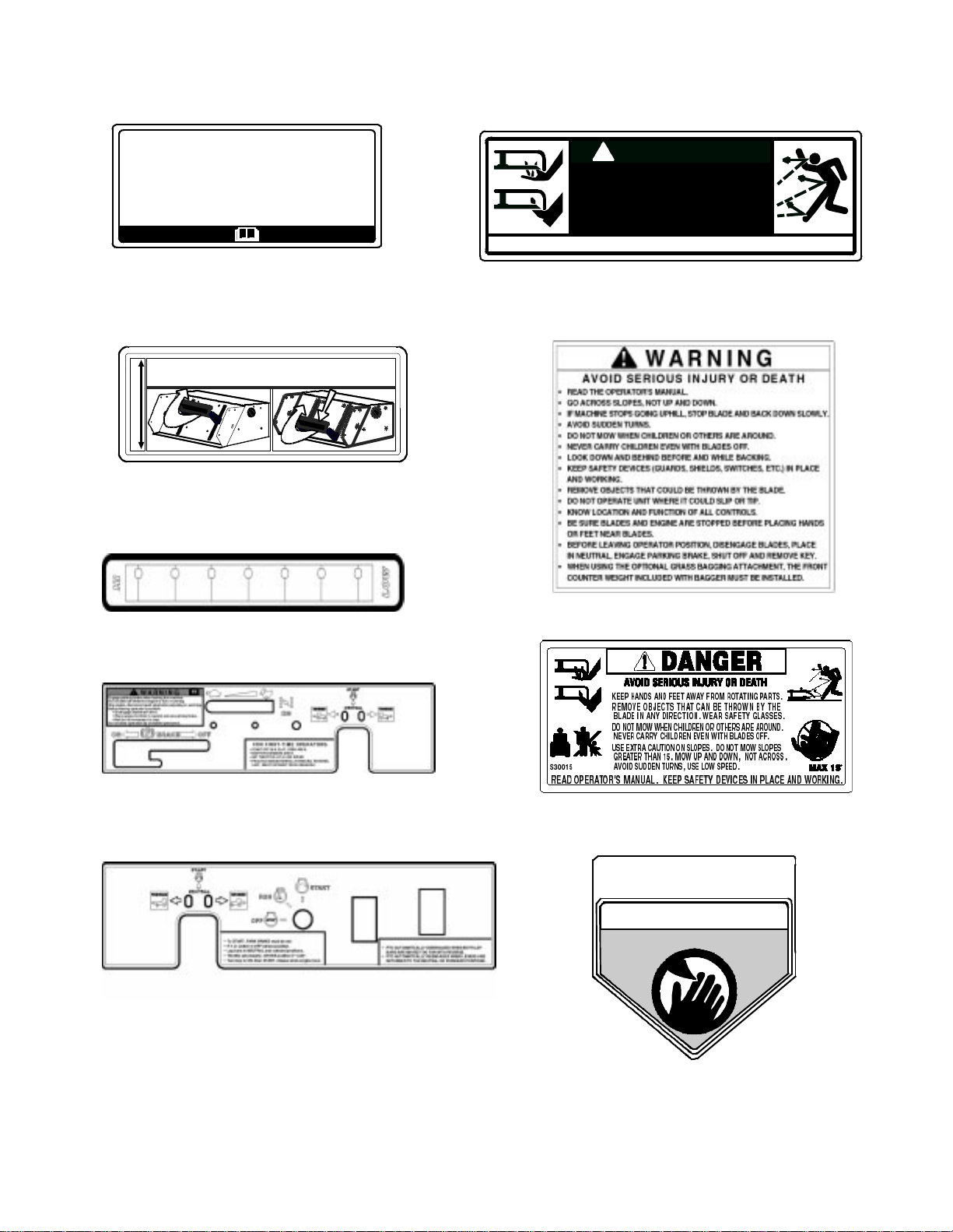
SAFETY DECALS AND LABELS
Belt
Routing
Part Number: 777I22421 (for 44” Deck)
To unlock, pull part of handle inward.
Lift unlock ed handle to in crease cuttin g height.
To lock, release upper part of handle to move outward.
LOWERCUTTI NG DECKHIGHER
Part Number: 777I22093
Part Number: 777I22094
I22093
KEEP HAND S AND FEET AWAY.
DANGER
DO NOT OPERATE MOWER
UNLESS CHUTE DEFLECTOR
OR ENTIRE GRASS CATCHER IS
IN ITS PROPER PLACE.
ASSEMBLE CHUTE DEFLECTOR TO THIS UNIT BEFORE OPERATING.
Part Number: 777S30503
Part Number: 777S32161
S30503
Part Number: 777I22290
Part Number: 777I22291
Part Number: 777S30015
TO REDUCE THE RISK OF INJURY,
DO NOT OPERATE MOWER UNLESS
DISCHARGE C HU TE COVER O R G R AS S
CATCHER IS IN ITS PROPER PLACE.
DANGER
KEEP HANDS and FEET AWAY
Part Number: 777S30145
7
Page 8

SPECIFICATIONS
Engine: 20HP & 23HP Kohler
Type: Vertical air cooled V-Twin
Air Cleaner: Paper element
Lube System: Pressurized with oil filter, drain valve with hose
Starter: 12-volt electric
Traction Drive: Engine to two variable-speed integrated hydraulic pump and
wheel motors on each drive wheel
Cutter Deck;Drive: 44" & 50” belt driven
Clutch: Electric
Deck Lift: Hand lever w/ lock for height adjustment
Cutting Height: 1-1/2" to 4"
No. of Blades 3, belt-driven, power take-off from engine
Controls: Engine ignition and start switch; throttle & choke; left and right
steering le ver s; ele ctric blade clutch s witch; parki ng br ake; mo wer
deck lift
Parking Brake: Mechanical linkage attached to the brake handle
Front Caster Wheels: 11 x 5.00 - 5
Tire Pressure: 8-10 psi rear, 20-25 psi front caster
Drive Wheels: 18 x 8.50 - 8 for 44” & 18 x 9.50-8 for 50”
Frame: Structural steel, all welded construction
Seat: Adjustable seat. 4" Adjustment, w/ arm rests
Fuel Tank: One 5 gallon with shut off valve
Ground Speed: 0-7 MPH forward. 0-3 MPH reverse
Instrumentation: Hour meter
Net Weight: 598 lbs w/44" & 618 lbs w/50”
8
Page 9

OPE RATING IN ST R U CT ION S
Figure. 1 Figure. 2
Hour Meter
Electric Blade
Clutch Switch
Ignition Switc h
A. General
1. When Mo wi n g:
a. Keep adults, children, and pets away from
the area to be mowed.
b. When operating this mower, in the forward
direction, do not allow the steering levers
to return to neutral on their own. Always
maintain a firm grip on the lev ers, operate
them smoothly and avoid any sudden
movements of the lev ers when s tarting and
stopping.
c. If the mower is equipped for side dis-
charge, never use the mower without the
discharge chute installed and placed in the
down position.
d. Always remove debris and other objects
from the area to be mowed (Note: debris
and loose grass will reduce traction).
e. Mow only in daylight or good ar t ificial light.
f. Watch f or holes, sprinkler heads, and other
hidden hazards.
g. Avoid driving too close to trees, creeks,
ditches, sand traps, and other obstacles.
h. Before backing up, check behind and
watch where you are going.
i. Always reduce speed when making a turn,
and when grass is wet.
j. Always mow across slopes, never up and
down the slope. Do not operate on steep
slopes and slow down before turning.
Avoid tur ning downhill if possible, start at
the bottom and work up to the top. Use
extra care and go slowly when turning
downhill. Control the speed and direction
of the zero turn machine “primarily” with
the speed/directional control (lap bar) of
the down hill s id e o f the machine...I .E.,
Choke
maintain the uphill side lap bar “essentially” in a fixed position.
k. Be careful when crossing gravel paths or
roadways. Always turn off the blade clutch
switch and wait until the blades stop rotating and raise the cutting deck to the transport position. Always allow other vehicles
to have the right of way.
l. If you hit a solid object while mowing, turn
off the blade clutch switch, place the steering levers in the neutral, opened-out position, move the throttle to slow, set the
parking brake, shut off the engine, and
take the key from the ignition switch.
Inspect for damage. Repair the damage.
Make sure the blades are in good condition
and that the blade bolts are tight before
restarting the engine.
m. Nev er leave t he mower unattended without
performing the following: turn off the blade
clutch switch, placing the steering levers i n
the neutral open-out position, moving the
throttle to slow, setting the parking brake,
shutting off the engine and taking the key
from the ignition switch.
n. Never walk or stand on the discharge side
of the mower when the engine is running.
Tur n off the blade clutch switch if another
person approaches while you are operating the mower.
o. Never attempt to operate the traction unit
without having the mowing deck attached.
p. Keep the mower and especially the engine
and hydraulic components clean and free
of grease, grass, and leaves to reduce the
chance of fire and permit proper cooling.
Engine throttle
9
Page 10

2. Safety Awareness when M owing
a. Do not operate on steep slopes, those
above 15 degrees (27% slope).
b. Avoid turning downhill if possible, use extra
care and go slowly .
c. Avoid turning when going downhill, traction
is at a minimum going downhill.
d. Do not operate with discharge side of the
mowe r toward streets, bu i l ding s , play-
grounds, parking lots, other machines, ani-
mals, and other people.
e. Avoid operation or use extreme care if the
traction surface is wet, unstable, or slip-
pery.
f. Use extra care when grass clippings,
leaves, pine needles, or debris are present
as traction can be reduced.
g. Slow-down before turn ing and come to a
complete stop before any zero t urn maneu-
ver.
h. Do not stop machine or park machine over
combustible materials such as dry grass,
leaves, debris, etc.
3. To Mow Grass and Produce a Striped P attern
a. Pick a point on the opposite side of the
area to be mowed (post, tree, shrub, etc.).
b. I f on a h ills i d e, sta rt at the bott om so that
the turns are uphill rather than downhill.
c. Align the mower so as to head directly
toward the object on the far side.
d. Slowly increase the speed of the machine
to match cutting conditions, terrain, and
operator familiarity with the controls and
keep the machine headed directly toward
the alignment object. Do not go fast as to
reduce cut quality or to be uncomfortable
in controlling the speed and direction of the
machine.
e. When approaching the other end of a strip,
slow down or stop before turning. A U-turn
is recommended unless a zero turn is
required. The speed of a U-turn that will
allow for machine controllability and minimal turf defacement will be dependent on
several factors including: the speed during
turning, the radius of the turn, the tire tread
pattern, the traction coefficient of the tire to
the traction surface, the slope of the traction surface.
f. Remem ber, a zero turn requires that the
forward or reverse travel of the machine be
stopped prior to the initiation of the turn or
severe turf defacement can occur.
g. To prevent rutting or grooving of the turf,
change the direction that the strips are
mowed by approximately 45 degrees the
next and each subsequent time that the
area is mowed.
B. Controls
Engine Ignition and Start Switch:
1.
ure 1.) Located on the instrument housing
below the rig ht side of the operator’s seat.
When the key is inserted and turned clockwise, 45 deg ree s, the ign itio n ci rcuit is cl osed.
Turning the switch further again st sp rin g pressure starts the engine. The engine will only
start if the blade clut ch switch is in th e “off”
position, the parking brake is engaged and
the left and right steeri ng lever s are in the
neutral, opened-out position. The ke y sh ould
always be re m oved from the switch if the
operator l eaves the mower’s seat.
Engine Throttle Control:
2.
Located on th e left side of the mow er next to
the operat or’s seat. Moving the t hrot tle c ontro l
from the rear to the front will increase the
engine spee d fr om slow to fast. Stop at the
detent, or the c hoke will be activated.
Left and Right Steering Levers:
3.
3.) These hinged le ve rs ope n out to the sid e in
the neutral position to permit the operator to
be seated or to leave the mower’s seat. The
operator, when seated, can pull th e levers up
to the operating position, a comfortable forearm’s length away. These levers control all of
the movements of the mower. Pushing both
lev ers forward causes the mower to move forward. Pulling both lev ers bac k causes the
mower to move bac k ward. Pushing one lever
ahead of the ot her lever cau ses the traction
wheel on the side where the lever is ahe ad t o
rotate f aster than the other traction wheel,
making the mo we r tu rn tow ard t he side w here
the le ver is behind. When on e l ever is pushed
forward and the other l ever pulled back the
same amount, one traction wheel will turn in
reverse a nd the mower will turn within its own
length.
In order to start the engine, both steering
lev ers must be opened out to the side in the
neutral position; the parking brake must be
engaged; and the blad e clu tch s w itch m us t be
“off”. Howev er, once the engine starts, the
parking bra k e must be release d before the
operator pl aces the steering levers into the
operating position or the engine will
automatically shut off.
Note:
neutral when released, but they should be
placed in neutral b y the driver. If the Drive
Handles are not placed in neutral, the tractor
may creep.
(See Fig-
(See Figure 2.)
(See Fi gure
The Steering Le ver will return tow ard
10
Page 11

Steering Levers
Brake
Figure. 3
Electric Blade Clutch Switch:
4.
Deck Lift Handle
(See Figur e
1.) Located on the right side of the mower
beside the i gnition swit ch . Thi s i s an “on/off”
push-p ull switch that c ont rols the electric
blade c l ut ch which supplies po wer to the cutting b lades through the PT O. The switch must
be turned off to start the engi ne and should
be turned off for safety any time another person approaches the mower or the mowing
deck is raised to the tr ansport position. Power
to the electric clutch will also be cut off if the
opera to r leaves the operator’s seat.
Parking Br ake :
5.
(See Figure 3.) Located on
the left side of t he traction unit. Th e handle is
an ov ercenter le ver which ap pl i es the drum
brake s on the driv e w heels when the handl e is
pulled to t he rear . The brak e mu st be enga ged
in order to start the engine.
Deck Lift H andle:
6.
(See Fi gure 3 .) Lo cate d on
the panel in fro nt of the seat. Raise the m owing deck to the transport position, by pulling
the han dle to the rear and m oving it up ward
for transport. To lower the mo wing deck, pul l
the deck lift handle to the rear and lower i t to
the desi red position .
Fuel Shutoff Valve:
7.
(See Figure 4.) Located
on top of the fuel tank. When turned in a
clockwise direction until it s tops, it w ill s hu t off
the flow of f uel to the engine. When turned in
a counterclockwise direction it will open and
allow fuel to flow to the engine. Close this
valv e if you ar e not going to run t he mo wer fo r
a period of 30 minutes or more to prevent
flooding the engine.
Figure. 4
Seat Adjustment Lever:
8.
Fuel Shutoff Valve
The Seat Adjustment Le ver is located beneath the seat. The
Seat Adjustment Lever is used to move the
seat fo rward and backward. To place the seat
in the desired position pull the seat adjustment lever to the left then push the seat forward or back to the desired position. Release
the lever so the seat will lock in place.
Hour Meter:
9.
(See Figure 1) Located on the
right side of the mower behind the i gnition
switch. The hour meter dis pl ays running t im e.
Note:
each recommended lubrication int erval. There
is a flashing “OIL” at each recom m ended
engine oil and filter change.
Choke Lever:
10.
There will be a flashing “LUBE” for
(See Figure 2) The Choke is
integr ated into the throttl e control which is
operated m anually. Having the Ch oke in the
ON (full forward) posi tion helps the engine to
start during initial st art-up. During normal
operation the Choke shoul d be in the OFF
(the detent for full throttle) position.
11
Page 12

C. Initial Adjustments
1. Chec k th e fluid levels and ti res:
Note:
before starting the engine.
a.
b.
Note:
mended oil weight refer to engine manual.
c.
d.
These checks should be made daily,
Fuel:
Using a good grade of unleaded,
regular gasoline, fill the fuel tank (beside
the engine on the left side of the mower).
When the fuel reaches one inch from the
top of the tank, stop. DO NOT O V ERFILL.
Space must be left for expansion.
Engine Oil:
(Filled at the factory before
shipment.) Pull out the oil dipstick, wipe it
off and reinsert it. Pull it out again and read
the oil level. If it is below the operating
range, add oil through the fill tube using a
funnel to bring it up to the top of the operating range.
Gasoline Engine: For the recom-
Hydraulic Oil:
(Filled at the factor y before
shipment.) The hydraulic oil is contained
within the integrated hydrostatic transaxles
and does not need to be checked or
replaced.
Tires:
8-10 psi rear, 20-25 psi front caster
tires
plugs and using the transport lever, lower
the mowing deck into the cutting position.
b. Using a ruler, pencil and paper, measure
and note the distance from the paved surface to the bottom edge of the mowing
blade at the front and the back of the deck
on each side of the mower. (Four dimensions.)
Note:
should be 1/8"-1/4" below the rear edge of the
deck so that the blades are cutting grass in
only the front half of their circular path. This
decreases fricti on and reduces the drive
power required.
The front edge of the mowing deck
c. If the dimension at the front of the mowing
deck is 1/8"-1/4" lower than the dimension
at the rear of the deck (pitch) on each side
of the mower, do not adjust. If not, you will
need to adjust the Deck Front Links (See
Figure 5).
Deck Lift Links
Deck Front Links
Note:
properly seat the bead to the rim. The normal
working pressure for the traction tires is 8-10
psi. The front caster wheels should be i nflated
to 20-25 psi.
New tires are overinflated in order to
2. Check that all Nuts, Bo l ts and Screws ar e
Tight.
3. Check the tension of the deck drive b elts.
a. Remove the deck cover
b. The tension of the deck drive belts are
maintained by a spring mechanism that
adjusts for wear and stretch.
c. Ex amine the belts for cuts, fraying, and
excessive wear. Replace if any of these
are detected.
d. Replace the deck cover.
Adjust the Mowing Deck:
4.
The cutting height
is set in 1/2” increme nts in the range of 1-1/2"
to 4". Do not at tempt to raise the mower deck
higher than 4” because you will damage components on your mow er. You may need to
adjust the mowing deck to achieve the proper
angle for mowing. Follow the procedures
below t o set the appropriate angle to the
mowing deck.
a. Park the mower on a flat paved surface,
engage the parking brake, shut off the
engine, remove the key from the ignition
switch, remove connection of the spark
Figure. 5
d. Lower the mower deck to the cutting posi-
tion. With a wrench, loosen the inner rear
nuts on the Deck Front Links adjust the
deck up or down, use a wrench and with a
few tur ns, adjust clockwise or counter
clockwise the outer rear nut of the Deck
Front Links. Repeat this procedure on the
opposite side of the Mower . Once the deck
is adjusted, retighten bolts.
e. With the deck still in the cutting position,
adjust the level (side to side). With a
wrench loosen the top inner nut of the left
side of the Deck Lift link. To adjust the side
of the deck up or down turn the lower nut
clockwise or counter clockwise a f e w turns.
Retighten nuts.
f. Raise the mowing deck to the transport
position using the transport lever.
g. Use the transport lever to lower the mow-
ing deck to the cutting position and repeat
step “b.” above to make sure that the
desired cutting height and pitch and level
12
Page 13

have been attained. If the dimensions are
not correct, repeat steps “c.” through “f.”
above.
5. Lubricate all fittings li sted in the maintenance section.
D. Zero Turn Break-In And Operating
Procedures
DANGER:
Reread the “When Mowing” Safety Precautions.
The following procedures are suggested for operators of ride-on machines which have zero turn
capabilities.
1. Orientation:
a. Read the entire Operator’s Manual.
b. Sit on the machine, adjust the seat fore-
and-aft, then adjust the speed/directional
(lap bar) controls (they can be adjusted
fore-and-aft, as well as up-and-down — 9/
16" wrench required).
c. Become familiar w it h all o f th e ma ch ine
controls, instrumentation, safety and
instruction signs, and safety devices.
d. Move (or have moved) the machine to a
safe, level area with no obstructions including objects, pedestrians, and animals.
2. Initia l Ope rat ion :
a. Use protective equipment for eyes, hands,
hearing, feet, legs, head and other areas of
the body if needed — safety eye glasses,
gloves, earplugs, boots, hats, etc.
W ARNING:
Hearing Protection is required for all operator
exposure exceeding two (2) hours.
b. Ensure that the area is free of animals and
bystanders, especially children!
c. Survey the area where the equipment is to
be used to make sure it is free of debris,
sticks, stones, wires, bones, and other foreign objects which could cause injury to
bystanders, damage to the machine, or
damage to nearby facilities.
d. Inspect the machine to make sure:
1. All guards, shields (including mower
chute deflector) are in their proper place,
are secure, and are functional.
2. That there are no spilled or leaking fuel
or oil sources, nor loose fuel or hydraulic
tank caps, hoses or fittings.
3. That there are no loose or missing hardware nor any missing items.
4. That no non-approved devices are
installed.
5. That all safety signs and decals are
properly installed and legible.
e. This is a one person mac hine, operator
only! Riders are not permitted under any
circumstance!
f. To start the engine on the machine:
1. Make sure the park brake is set to the
“ON” position, both lap bars are in the
neutral/start (opened-out) position, and
the Power Take Off (PTO also referred to
as blade control switch) is in the “off”
(down) position.
2. Move the choke and the engine speed
control (throttle) forward to the end of the
slot.
3. Inser t the ignition key, tur n the switch
toward the spring-loaded “Start” position,
maintain the Start position until the
engine begins to run, then release the
switch (it will return to the “Run” position).
4. Move the choke/speed control slowly by
moving it rearward. If the engine is
“cold”, the choke may need to be partially applied for a few minutes. Be sure
to move the choke/throttle after the
engine has “warmed up” to the detent.
g. Check safety devices:
1. With the park brake engaged, move one
of the lap bars (speed/directional control)
from the neutral/start position to the neutral position (out of the slot, toward the
center of the machine) — the engine
should stop running. Move the lap bars
back to the neutral/start position and the
engine should run.
2. Repeat this procedure with the opposite
side lap bars.
3. With the park brake engaged and the lap
bars in the neutral/start position,
advance the engine speed control completely forward (Hi-idle), engage the PTO
control switch (pull upward), then lift off
the seat — the engine should stop running. Sit down and the engine should
run. Turn off the PTO by pushing the
control switch down.
h. To drive in the FORWARD direction:
1. Set the engine speed to 2000 to 2500
rpm (refer to optional tachometer on
right control panel). This must be
increased to full speed (3525-3675 rpm)
after becoming familiar with the machine.
2. Release the park brake.
3. Move both lap bars out of the neutral/
start position to the neutral position
13
Page 14

(toward center of machine). Slowly, move
both lap bars toward the front of the
machine until the machine begins to
move forward — release the lap bars
and the machine should stop. The more
that the lap bars are moved toward the
front of the machine, the faster the
machine will move in the forward direction. Release the lap bars and the
machine should stop traveling f o rward.
(This is a safety check, the normal procedure is for the operator to slowly bring
the lap bars to the neutral position).
4. Do not advance the lap bars rapidly as
this could cause turf defacement, loss of
traction, and/or instability.
5. To turn, advance one lap bar ahead of
the other and the machine will turn
toward the opposite from the side that
was advance d — I.E. to turn clockwise
(to the Right), move the LEFT lap bar f orward more than the right side, and to
turn counter-clockwise (to the LEFT),
move the RIGHT lap bar forward more
than the left side. NOTE: If one lap bar is
in the neutral position and the other is
advanced, the turn side tire will not
rotate and a “pivot turn” will be executed
— turf defacement could occur (if on
grass) as well as potential damages to
the traction surface and the tire. If the lap
bar on the turn side is not brought all the
way to neutral, then the turn side tire will
continue to rotate and a “U-turn” will be
executed with a low potential for turf
defacement as well as traction surface
and tire damage.
i. To drive in the REVERSE direction:
1. Make sure no bystanders, animals, or
objects are behind the machine. Look
behind the machine, and use extreme
care.
2. Slowly, move both lap bars toward the
rear of the machine until the machine
begins to move rearward. Release the
lap bars and the machine should stop.
The more the lap bars are moved toward
the rear of the machine, the faster the
machine will move in the reverse direction. Release the lap bars and the
machine should stop traveling in reverse
(this is a safety check, the normal procedure is for the operator to slowly bring
the lap bars to the neutral position).
3. Do not move the lap bars rapidly as this
could cause turf defacement and/or loss
of tracti o n.
4. To turn, move one lap bar ahead of the
other and the machine will turn toward
14
the same side that was moved — I.E., to
turn counter-clockwise (to the LEFT),
move the LEFT lap bar rearward more
than the right side, and to turn clockwise
(to the RIGHT), move the RIGHT lap bar
rearward more than the left side. NOTE:
If one lap bar is in the neutral position
and the other is moved, the turn side tire
will not rotate and a “pivot turn” will be
ex ecuted. T urf defacement could occur (if
on grass) as well as potential damages
to the traction surface and the tire. If the
lap bar on the turn side is not brought all
the way to neutral, then the turn side tire
will continue to rotate and a “U-turn” will
be executed with a low potential for turf
defacement as well as traction surface
and tire damage.
j. T o perform a “zero turn”:
1. Please note, a zero turn maneuver can
not be executed while the machine is
moving in the forward or, reverse directions, the machine must come to a stop
first.
2. To turn clockwise, slowly move the LEFT
lap bar forward while simultaneously
moving the RIGHT lap bar rearward.
Release both lap bars and the machine
should stop turning.
3. To turn counter-clockwise, slowly move
the RIGHT lap bar forward while simultaneously moving the LEFT lap bar rearward. Release both lap bars and the
machine should stop turning (this is a
safety check, the normal procedure is for
the operator to slowly bring the lap bars
to the neutral position).
3. Start the Engine:
a. Open the fuel shutoff valve.
b. Sit on the Seat. Set the parking brake
“On”.
c. M ove the left and right steering levers to
the neutral, opened-out position.
d. Tur n the electric blade clutch switch “Off”.
e. Push the choke/throttle control to the full
forward position.
f. Insert the key in the ignition and start
switch and turn the switch to “On”.
g. Tur n the ignition key in a clockwise direc-
tion to the “Start” position until the engine
starts.
Note:
position fo r more than 10 seconds or you may
damage the starter . If the engi ne does not start
in this time, wait about 30 seconds and try
again.
Do not hold the key in the “Start”
Page 15

h. Gasoline Engine: Once the engine starts,
move the choke/throttle to the detent as
the engine warms.
Operatin g the Mower :
4.
ing-ra di us mower is not like operating a tractor-typ e riding mo wer . The z ero-turning -rad ius
mower is much more maneuverable and
much les s fatiguing to operate. Ho weve r, getting use d to the fingertip control of the zeroturning-radi us mower ta kes some prac t i ce.
We strongly recommend that you locate a
“test area” where you can operate the mower
for about 30 minutes without being disturbed.
a. Get into the operator’s seat.
b. Start the engine.
c. Use the transport lever to r aise the mowing
deck to the transport position. Make sure
the blade clutch switch is off.
d. After the engine has warmed, adjust the
throttle to the fast position.
e. Release the parking brake.
f. Fold in the steering levers to the operating
position.
Operating a zero-turn-
WARNING:
When operating this mower forward, do not
allow th e steerin g levers to return to the ne utral position on their own. Always maintain a
firm grip on the steering levers, operate them
smoothly and avoid any sudden movements of
the levers when starting or stopping.
g. To go forward, move both steering levers
slightly forward and the mower will slowly
move forward. The farther you move the
levers forward the faster the mower will go
forward.
h. To back up, move both steering levers
slightly backward and the mower will slowly
move backward. The farther you move the
levers backward the fa st er the mower will
go backward.
i. T o turn, pull the lever back on the side to
which you want to turn. The farther back
you pull the lever, the faster and more
sharply you will turn. Initially, you will have
to be careful to avoid tur nin g too fast and
too far.
j. After you have mastered operating the
mower, use t he tr ansport lev er to lower the
mowing deck to the cutting position and
pull on the electric blade clutch switch to
star t the blades rotating.
k. Practice mowing in straight passes. When
you feel confident, slowly practice mowing
around obstacles such as trees.
5. Parking the Mower:
a. Push off the electric blade clutch switch.
b. Use the Deck Lift Handle to raise the mow-
ing deck to the transport position.
c. Dr ive the mower to the cleanup or storage
area.
d. Move the throttle to slow.
e. Place the steering levers in the neutral
position.
f. Set the parking brake.
g. Turn off the ignition switch and take the ke y
from the switch.
h. Close the fuel shutoff valves.
MAINTENANCE AND
SERVICE
WARNING:
Disconnect the spark plug wires or remove the
key from the ignition to prevent the engine
from accidentally starting before performing
any maintenance on this mower.
A. Cleaning your Deck
Use the Deck Wash System to rinse grass clippings fro the deck’s underside and prevent the
buildup of corrosive chemicals. Complete the following steps
IMPORTANT:
charge chute is directed
dren, animals, and your house, garage, parked
cars, etc.
a. Drive the machine to a level, clear spot on
your lawn, near enough to a water faucet
(spigot) for your garden hose to reach.
b. Make sure that the PTO (mower deck
blade engage) control is in the “OFF” posi-
tion.
c. Move shift le ver or speed control into the
“Neutral” position.
d. Set the parking brake, and turn the ignition
key to the “STOP” position to stop the
engine.
e. Thread hose coupler (packaged with this
manual) onto the end of your garden hose.
See Figure 7.
f. Attach the hose coupler to the water port
on your mower deck’s surf ace. See Figure
7. Turn the water on.
g. While sitting in the machine operator’s
position, re-start the engine and pla ce
throttle lever in the Fast (rabbit) position.
h. Move the PTO control to the “ON” position.
i. Remain in the machine operator’s position,
and with the mower deck engaged for a
minimum of two minutes per wash out,
start with the trim (oper ato r’s left) si de, and
after
each mowing:
Make certain the machine’s dis-
away
from people, chil-
15
Page 16

Linch Pins
Figure. 6
“J” Pin
allow the underside of the cutting deck to
thoroughly rinse.
j. Move the PTO control to the “OFF” posi-
tion.
k. T urn the engine off.
l. T urn the water off, and detach the hose
coupler from the water port on your mower
deck.
m. Clean up the grass clippings and other
materials washed from undern eath the
mower deck, and dispose of them properly.
Hose Coupler
(Shown without
Hose Attached)
Wate r Port
Figure. 7
B.Mower Deck
1. Removing the Mower Deck:
a. Apply the parking brake. Remove ignition
key and both spark plug caps.
b. Lower the cutter deck to the ground. Cap-
ture the lift handle by placing the height of
cut clevis pin above the lift handle.
c. Remove tension of the PTO belt by moving
the belt tensioning rod.
Note:
tension due to the weight of the deck. When
removing t he lift linkage from the deck the tension of the springs will go from the deck to the
lift handle. Not capturing the lift handle while
removing the lif t linkage from the deck will
cause it to snap back.
There is a certain amount of spring
d. Detach the mower drive belt.
e. Remove two linchpins (See Fig. 6) from the
front of the mower. Pull the two (2) springloaded “J” pins on the left and right rear
side of the cutter deck.
f. Turn front caster wheels outward.
g. Shift the deck toward the ignition switch
side of the mower and remove.
h. To install reverse the process.
2. Chang ing a Blad e :
a. Remove the key from the ignition and dis-
connect the spark plugs.
b. Jack up the front of the mowing deck about
one foot and block it in that position.
c. Wrap a rag around one end of the blade
and grasp it to prev ent it from turning, or
secure the blade by placing a block of
wood between the blade and the deck
housing.
d. Use a 1-1/8" socket wrench on the pulley
side of the spindle bolt.
e. Remove the hex nut at the blade using a 1-
1/8" wrench.
f. Remove the blade.
g. To replace the blade reverse the above
process and tighten nut to 100-120 lb ft.
16
Page 17

WARNING:
Never mow with dull blades! Blades that are
bent should be replaced! The cutting blades
are sharp and can cause severe injury. Wrap
the cutting surface of the blade with a rag to
avoid injury.
3. Sharpening the Blade:
a. Set the parking brake.
b. Clean any debris from the blades. Keep
blades sharp and free of build up at all
times.
c. Sharpen blades evenly at the original 30°
angle to maintain balanced cutting blades.
Do not sharpen the underside of the
blades. Use a electric blade sharpener, a
conventional electric grinder or a hand file
to sharpen the blades.
d. Replace any blade with severe nicks or
dents that cannot be removed by filing.
e. Check the balance of the blade after
sharpenin g by placing it on a blade balancer. Do not use un-balanced blades.
f. If the blade dips on one end, file stock off
of the cutting surface on that end.
Note:
anced—REPLACE.
4. Changing the Blade Drive Belts:
a. Set the parking brake. Remove ignition ke y
b. Unscrew the wing nuts from the deck covc. Usin g a 3/8" socket breaker bar or socket
d. Remove tension of the PTO belt by moving
e. Pull the tensioner pulley away from the belt
f. Reverse the process to install the belt.
Blades that cannot be easily bal-
and both spark plug caps.
ers and remove both covers.
ratchet insert the drive end into the 3/8"
square opening in the lower idler arm
assembly and push the idler arm counterclockwise. While holding the idler arm
back, loosen the blade drive belt from the
pulley and slide the belt away from the pulley.
the belt tensioning rod. Loosen the belt
retaining bolt.
and remove the PTO belt then remove the
blade drive belt.
Figure 8
Spindle
5. Chang ing the Spindle As sembly
a. Jack up the front of the mowing deck about
one foot and block it in that position.
b. Make sure the blade clutch is disengaged.
c. Remove the deck cover.
d. Remove the drive belts. (See 3. Changing
Blade Drive Belts.)
e. Remove the cutter blade. (See 2. Chang-
ing a Blade.)
f. Using a wrench or socket ratchet remove
four hex nuts, and the four hex head cap
screws. Remove the spindle assembly.
g. Reverse the process to install the spindle
assembly.
C.Hydrostatic Drive System
1.
Your zero turn riding mower is equipped wi th
dual integrated h ydro static pumps, motor s, and
planetary gear reduction transaxles tha t are
sealed and do not require service, maintenanc e,
or adjustments
.
Note:
tighten. Adjus t the idler pulley so that a tenpound pull with a spring scale between two
pulleys defl ects the belt about 1/2".
When replacing belts do not over-
17
Page 18
c. Store the battery with a full charge. A dis-
charged battery will freeze (refer to the
table below).
Specific Gravity Freezing Temp (°F)
Hydrostatic
Transaxles
Figure 9
D.Electrical Circuit
Danger:
Read General Safety Precautions Nos. 9 and 10.
Battery:
1.
operator’s seat. If so equipped, remove the fillcaps and che ck the level of the liquid electrolyte in the battery every 50 operating hours. If
the le vel in any of the s i x c el ls has dropped
below the bottom of the split ring inside the fill
hole, refill the cell with distilled water. To keep
the outsid e of the battery clean, brush on a
strong so l ut i on of bi carbonate of soda and
water and rinse with clean wat er. Keep the
contact s an d cable ends clean with a wire
brush and make sure the connections are
tight. Coat the terminals with petroleum jelly
to prevent corrosion.
2. Battery Removal
The battery is located beneath the
Warning:
When removing the cables from the battery
follow these steps to avoid a short between
the wrench and the frame.
a. Remove the negative (black) cable.
b. Remove the positive (red) cable.
c. Release the hold down straps.
d. Remove the battery without tipping.
Battery Stora ge:
3.
long periods of t i m e th e following guidelines
should be performed.
a. Disconnect the battery cables from the ter-
minals and remove the battery.
b. Clean the battery before storing. A dirty
battery will lose its charge over time.
When st oring the mo w er for
1.265 -71
1.250 -62
1.200 -16
1.150 5
1.100 16
d. Re charge batter y when ever the specific
gravity value is less than 1.225
4. Installing the Battery
Note:
tory fully charged and filled with electrolyte.
a. Attach the positive (red) cable.
b. Attach the negative (black) cable.
c. Attach the rubber battery strap.
5. Jump Starting
The battery is delivered from the fac-
Warning:
Failure to use this starting procedure can
cause sparking, and the gases in the battery
to explode.
a. At tach the end of the red jumper cable to
the positive terminal (+) of the charged battery.
b. At tach the other end of the red jumper
cable to the positive terminal (+) of the low
charge bat t ery.
c. Attach the end of the black jumper cable to
the negative terminal of the charged battery.
d. At tach the other end of the black jumper
cable to the frame of the unit with the low
charge bat t ery.
Fuses:
6.
between th e i gnition and start switch and
other electric al components. Thi s is a standard plug-in type automotive fuse rated at 7.5
amp.
Safety Switches:
7.
switches in the el e c trica l c i rcuit whi ch control
the engine. They are (1) the blade clutch
switch, (2) the parking brake swi t ch, (3) the
left and (4) the right steering lever switches,
(5) the seat switch, (6 and 7) the no cut in
rev erse swi tches. The y oper ate so t hat in order
to start the engine, the blade clutch switch
There is one f use lo ca ted in t he wi ring
There are seven safety
18
Page 19

must be off, the parking brake must be
engaged , and both steering levers must be
opened- out to the side in the neut ral position.
Once the engine is started, the seat mu st be
occupied and the parking brake must be
released before either of the steering levers is
folded up to the operating position or the
engine’s electronic ignition will be grounded
out and the engine will stop. Also, the seat
must be occ upied befor e the blade clutch
swi tch can cause the blades to rotate.
Safety Switch Operation Checks:
8.
lowing operational ch ecks should be made
daily.
Blade Clutch Switch:
a.
Sit in the operator’s
seat. With both steering levers opened-out
in the neutral position and the parking
brake engaged, turn the blade clutch
switch “on” and try to start the engine. The
engine should not start. If it does, the blade
clutch switch must be replaced. If the
engine does not start, turn the blade clutch
switch “off” and start the engine. Now turn
the blade clutch switch “on” and the blades
should rotate. If the blades do not turn, the
blade clutch switch must be replaced, the
seat switch must be replaced or the electric PTO clutch must be repaired. The airgap should be checked every 100 hrs. (or
less, if severe operating conditions exist
such as when there are many on/off
cycles, mulching operations, material collection systems used, and dusty/dirty conditions), and the air-gap adjusted if more
than 0.025". To inspect, remove the “negative” cable from the batter y and all sparkplug wires. The air-gap should be checked
with feeler gages in the three slots of the
BBC (PTO Clutch). The air-gap should be
adjusted to 0.012" to 0.015". There are
three inspection slots in the brake cover . To
adjust, successively tighten each of the
three gap adjustment nuts an equal
amount. Insert a feeler gage (0.012" to
0.015") into each slot as the air gap adjustment nut are tightened. The correct adjustment occurs when slight contact with the
feeler gage occurs. Engage the BBC (PT O
Clutch) a couple of times, and re-check the
air-gap. If it is not between 0.012" and
0.015", repeat the adjustment procedure.
Parking Brake Switch:
b.
Sit in the operator’ s seat. With both steering levers
opened-out in the neutral position and the
blade clutch switch “off”, release the parking brake and try to start the engine. The
engine should not start. If it does, the park-
The fol-
ing brake switch must be repositioned or
perhaps replaced. If the engine does not
start, engage the parking brake and start
the engine. Swing one steering lever up to
the operating position and the engine
should stop. If the engine does not stop,
the parking brake switch must be repositioned or replaced.
Left and Right Steering Lever Switches:
c.
Sit in the operator’s seat. With both steering levers opened-out in the neutral position, the parking brake engaged and the
blade clutch switch “off”, swing the left
steering lever up to the operating position
and try to star t the engine. The engine
should not start. If it does, the left steering
lever switch must be repositioned or perhaps replaced. Open the left steering lever
to the neutral position and swing the right
steering lever up to the operating position
and try to star t the engine. The engine
should not start. If it does, the right steering lever switch must be repositioned or
perhaps replaced. If the engine does not
start, open the right steering lever to the
neutral position and start the engine.
Swing the left steering lever up to the operating position and the engine should stop.
If the engine does not stop, the left steering
lever switch must be repositioned or
replaced. Open the left steering lever out to
the neutral position and start the engine.
Swing the right steering lever up to the
operating position and the engine should
stop. If the engine does not stop, the right
steering lever switch must be repositioned
or replaced.
Seat Switch:
d.
With both steering levers
opened-out to the neutral position, the
parking brake engaged and the blade
clutch switch in the “off” position, start the
engine. Now release the parking brake,
hold down on the back of the operator’s
seat against spring pressure, and swing
one of the steering levers up to the operating position. Release the operator’s seat
and the engine should stop. If the engine
does not stop, the seat switch must be
replaced. With both steering levers folded
out in the neutral position, the parking
brake engaged and the blade clutch switch
in the “off” position, sit in the operator’s
seat and start the engine. Turn the blade
clutch switch to the “on” position and the
blades should start to rotate. Raise up
slightly off the operator’s seat and the
blades should stop. If the blades do not
19
Page 20

stop when you dismount from the operator’s seat, the seat switch must be
replaced.
Electric PTO Clutch:
e.
when the engine is running, the operator is
in the operator’s seat and the blade clutch
switch is turned on. This electric clutch is a
fairly trouble free device. If a problem
develops and the blades do not turn, first
check the 20 amp fuse in the yellow, 16gauge wire between terminal “L” on the
ignition switch and the hour meter and then
investigate the wiring harness and the connections to the seat switch, the blade
clutch switch and the electric blade clutch.
Then check the seat switch, the blade
clutch switch and finally the electric blade
clutch.
f. No Cut in Reverse Switches:
speed/direction levers are moved past
“neutral” to reverse the PTO Clutch will be
deactivated and the mower blades will stop
rotation. The PTO will be reactivated when
one or both of the levers are moved back to
“Neutral”.
This clutch operates
When both
E.Tires
The two front wheels are caster wheels that are free
to swivel to accommodate the direction of the mower.
The two rear wheels are used to propel the mower in
the direction of input from the drive handles. Inflation
pressure of the rear tires is important for stability
while the mower is in operation. If the tire diameter is
not equal between the two tires, the mower will pull to
one side .
Inflation Pressure:
1.
a. Traction Tires—20 psi max; 8-10 psi rec-
ommended
b. Front Caster Wheel—28 psi max; 20-25
psi recommended
c. Cutting Deck Ball Wheels—Solid Polyure-
thane.
Use the Following guidelines for maintaining the tires:
a. Balance inflation pressure between the
rear tires to help maintain straight travel
(see tire side wall for proper inflation pressure).
b. Keep the valve caps tightened to prevent
air pressure loss.
Leaking Tires:
2.
or repla ce immed iately. The normal procedu re
is to remo ve the wheel and replace it. If a tir e
is getting soft, park the mo wer on the neare st
level, paved area. If the leaking tire is on a
tractio n wheel, put blocks on each side of the
opposite traction wheel and jack up the tire
When a fl at tire occurs, repair
that leaks ab out an i nch off the ground.
Loosen and rem ove the lug nut s and remov e
the wheel. M ount a whee l and tire , repl ace the
lug nuts, and using a torque wre nch, tighten
10 ft-lbs.
them to 60
If the leaking tire is on a front caster wheel,
block both traction wheels and raise the
caste r whee l s o that t he tir e is a n i nc h of f t he
ground. Loosen and remove the locknut from
the axle assembly and pull the axle assembly
from the caster yoke. The wheel and two
spacer sleeves will drop free. Slip the axle
assembly through one side of the caster
yoke, through a spacer sleeve, a wheel, the
other spacer sleeve and finally through the
other side of the caster yoke. Then tighten
the locknut on the end of the axle assembly.
Lower the mower off the jack and continue
mowing. The wheel with the leaking tire
should be inflated to 20 psi and the wheel
placed in a large bucket of water. Carefully
inspect the tire, rim and valve for escaping air
bubbles which indicate a leak. Mark each
leak with a yellow marking crayon and then
deflate the tire to 8 psi and repeat the
inspection. If the leaks you find are pin hole
size to 1/16" diameter, the tire can be
repaired. If the leaks are larger than 1/16"
diameter, the tire can be repaired. If the tire
bead is damaged, the tire can be repaired or
the tire will have to be replaced.
Creeping:
3.
backward movement of the mo wer when the
throttle is on and the lapbars are in the
opened-ou t position. If y our mower cr eeps do
the following.
a. Jack up rear of unit.
b. Place Lapbars in neutral opened-out posi-
tion.
c. Locate jam nuts on transaxle control arms.
(They are on the vertical linkage on the
front of the transaxles)
d. Loosen jam nuts on both ends of rod con-
nectors.
e. Start unit and push throttle all the way on.
f. If unit creeps forward, rotate vertical rod
links counter-clockwise. If unit creeps in
reverse, rotate clockwise.
Adjust the appropriate rod c onnector. The
left rod for the left side of the mower and
the right rod for the right side of mower.
Afterward, retighten jam nuts.
±
Creeping is the slight forward or
F. Brakes
While the mower is in motion, all braking is performed
dynamically through the hydraulic pumps and traction
motors, controlled by the two steering levers. When the
mower is parked with the engine shut off, the hydraulic
20
Page 21

system l oc ks th e trac tion whee ls .
Note:
reverse by pushing, you must release the
dynamic braki ng. Locate the release levers at
the rear of the machine. Pull them toward the
rear and lower the wide a rea of the r od int o the
keyhole slot. (See photo below)
To move the mower forward or in
.
Hydro Release Valve
When the mower is parked with the engine running
and the steering levers opened out in the neutral
position, the parking brakes should be applied. The
parking brakes are gear/pawl brakes mounted on
each traction wheel. They are both engaged by the
same operating lever.
Adjustments:
1.
The parking br ake handle is a
lever in a “j” slot that s hould engage wi t h m oderate force. The parking brakes provide a
positive means to hold a machine stationary
that is similar to “Park” on an automobile.
Note:
need to be adjusted.
The parking brakes norm ally do not
To adjust eith er brake indiv i dually, loosen t h e jam nuts
on the cable near the brake arm on the transaxle.
Adjust the nuts so that the brak e/ pawl comes close r to
the gear, but not in contact with the gear teeth.
Repair:
2.
The mower is equipped with external
gear/pawl bra kes and will n ot normally require
maintenance. If they are not working properly,
please contact your service center.
G. Hydraulic System
Hydrostatic Pum ps and Motors:
1.
in the transaxles are the hardest-working
compone nts in the h ydr aulic syst em. They are
in oper ation all the time the engine is running.
Because of extremely clos e tolerances, wear
is an important factor in their life.
Note:
owner -repairable. If a pump fai ls, contact your
Cub Cadet dealer. Do not disassemble the
pump/motors .
The pumps and motors are not
The pumps
Steer ing Leve r Adjustments:
2.
Place the
mower on level ground with the engine running, parking brake off and steering levers
opened out to the neutral posit ion. If the
mower begi ns to creep, adjust the steering
levers .
If the mo w er cr eeps , fir st d et ermine w hethe r it
creeps to the right or left sid e and which dir ec tion the mower moves — to the front or the
rear . To make the adjustm ent , place the steer ing levers in the opened-out neutral position
and set the pa rking brake , shutoff the engine,
take the k ey from the i gnition swit ch and pivot
the seat forward. If the mower creeps to th e
right, you will adjust the linkage on the left
side of th e m ower and vice-versa. Loosen the
jam nut whic h prevents the linkage rod from
turning. If the mower creeps forward, turn the
linkage rod c ounterclockw i se . If the mower
creeps bac kward, turn the linkage rod clockwise. Th en tighten the jam nut s.
H. Storage
General:
1.
for a few months, it should be st ored in a dry
location that is not subject to dra st ic c hanges
in temperature. Before storing, the following
maintenanc e procedures should be performed.
a. Clean the mower. The entire tractor and
cutting deck should be washed and
cleaned.
b. Sharpen the blades so that the mower will
be ready to use when needed.
c. Protect the metal surfaces. Repair
scratches with the appropriate touch-up
spray paint. Brush a rust preventive oil on
any unpainted surfaces including the pulleys and blades. (Be careful not to get any
oil on the drive belts.)
d. L ubri cate the mower.
e. Drain the engine oil. The engine should be
warm so that all the oil drains. Replace the
engine oil filter and refill the crankcase with
fresh oil.
f. Gasoline Engine: Drain all the fuel. Close
the fuel tank shutoff valve. Disconnect the
fuel line from the carburetor and put the
end into an approved fuel container. Open
the fuel tank shutoff valve and drain the
fuel tank and line into the approved con-
tainer. Replace the fuel line on the carbure-
tor. Start the engine and allow it to run out
of fuel. This will prevent gum and varnish
If your mower will not be in service
21
Page 22

deposits from forming. Replace the fuel filter.
g. Gasoline Engine Only: Rem ove the spark
plugs and pour approximately one ounce
of oil into each cylinder. Crank the engine
one or two turns to spread the oil evenly on
the cylinder walls. Replace the spark
plugs.
h. Clean the battery and make sure it is fully
charged.
i. Jack the mower up and store it on b lock s to
take the weight off of the tires.
2. To Put the M o wer Back in Se rv ic e:
a. Check the battery. Charge if necessary.
b. Gasoline Engine Only: Rem ove the spark
plugs and wipe them off. Using th e starter,
crank the engine to pump the excess oil
out of the spark plug holes. Replace the
spark plugs and the ignition lea ds. Refill
the fuel tank with fresh gasoline.
c. Check the level of the oil in the crankcase
and the hydraulic tank.
d. Lower the mower off the block and check
the tire pressure.
e. Push the mower outdoors and start the
engine. Let the engine idle until it has
warmed up completely (4 to 5 minutes).
B. Every 25 Hour Checks
1. Service the engi ne foam eleme nt air cleaner.*
2. Grease the three spindle bearings.
C. Every 50 Hour Checks
1. Chang e the eng ine oil . (E v ery 25 hours unde r
heavy dut y operation.)
2. Clean or replace the engin e ’s paper air
cleaner elem ent.*
3. Check the battery’s electrolyte level, if
equipped with fill caps.
4. Clean th e engine cooling fins and external
surfac es.*
5. Lubricate wear points.
6. Lubricate all grease fittings .
Lubrication Chart.
Follow the Oil Chart.
Follow the
D. Every 100 Hour Checks
1. Chang e the engine oil filter. (Every 50 hours
under hea vy duty operatio n. )
2. Chec k the engine spark plugs.
3. Chec k the air gap on the bl ade brake clutch
(PT O Cl utc h) a nd if i t e xc eeds 0.02 5” a djust to
0.012” - 0.015”.
* Perform maintenance more frequently under dusty
conditions.
**Reference Engine Owner’s Manual
MAINTENANCE SCHEDULE
A. Daily Checks
1. Before starting engine :
a. Check the fuel lev el b y viewing in the tank.
b. Check the engine oil level.**
c. Check the hydraulic transaxels for leaks.
d. Check the tires and tire pressure.
Drive Tires: 8-10 psi.
Front Caster Wheels: 20-25 psi.
e. Check the spindle belt, the mower drive
belt and the hydro drive belt.
f. Check the blades. Make sure they are
sharp and that the blade securing cap
screws are tight.
g. Check the cutting height.
2. When ready to start the engin e:
a. Check the se ven saf ety s witches f or proper
operation.
3. After mo wing:
a. Clean the mower.
b. Clean the engine air screen.
c. lubricate the wear points. Follow the Lubri-
cation Chart.
d. After the first five hours, change the engine
oil and engine oil filter.
22
Page 23

.
OIL CHART
Apply a few drops of SAE 20W-50 engine oil, grease, or use a spray
lubricant. Apply the oil to both sides of pivot points. Wipe off any excess.
Start engine and ope rate mower brie fly to insure that oil spr eads evenl y.
Number of Oi l Points Description
DAIL Y
4
4
2
2
2
2
1
2
WEEKLY
1
2
2
2
2
Deck Suspension Pivots
Height Adjustment Turnbuckle Clevis Pin
Height Adjustment Handle Pivots
Height Adjustment Stop Pivots
Deck Lift Linkage Pivots
Transport Handle Pivots
Transport Handle Pin
Deck Frame Up-and -Down Pivots
Seat Hinge
Steering Lever Lin kage Rod End Bearings
Lever Return Assembly Rod End Bearings
Pump Control Lever Pivots
Gras s C ol l ection System Lid Hi nges
(If Mower is so equipped)
LUBRICATION CHART
Use a grease-gun filled with NO. 2 Multipurpose Lithium Base Grease
No. of Grea se Fitti n gs Descriptio n
EVERY 25 HOURS
3
WEEKLY
2
2
4
2
2
Blade Spindle Bearings
Front Caster Wh eels
Front Caster Wheel Spindles
Mow ing D eck P ivots
Deck Take -Up Idl e r Pivot s
Mower Deck Ball Wheels
23
Page 24

P erformance Adjustments
A. High Speed Tracking Adjustment
If mower tracks to one side with both lap bars in fully
forward pos i tion:
B. Engine RPM Check and Adjustment
Table 1
Description High RPM Spec. Low RPM Spec.
20 Kohler 3400 +/-75 1550 +/-100
23 Kohler 3475 +/-75 1550 +/-100
NOTE:
RPM Specs. are for free running engines under no load.
1. Check air pressure in all four tires:
a. Pressure should be within specified ranges
and balanced side-to-side.
b. Rear tires 8-10 psi recommended (20 psi
MAX.)
c. Front tires 20-25 psi recommended (28 psi
MAX.
2. V erify that the mow er does not creep when
the engin e is running, the lap bars are in the
neutral position and the pa rking brake is
release d. (Refer to section D-3 on page 19 of
this manual if this condition exists).
3. Recheck the tracking after any adjustments
based on the above.
4. If uneven tracking persists, adjust as foll ows.
(see Fig. 10)
a. Unit tracks to the RIGHT, adjust Left lap
bar stop bolt to make it longer.
b. Unit tracks to the LEFT, adjust Right lap
bar stop bolt to make it longer.
5. Re-check the tracking and m ake any fine tun-
ing adjust m ents to the lap bar stop bo l ts as
require d.
Note:
ing problem will change sides. Make the fine
tuning adjustments by shortening the same
bolt.
Figure. 10
If stop bolt is adjusted too far, track-
Lap Bar Stop Bolt
1. Ve rify that the lap bars are in the neutral position, the parkin g brake is on, and th e PTO
drive is dis engaged.
2. Start the mower and le t it run at appro xima tely
half throttl e for 3-5 minut es to bring the eng ine
up to operat i ng temperature .
3. Locate the (optional) Hour Meter/ Tachom eter/ Service Minder display on the right hand
operator c ontro l pa nel if s o equ ippe d, or u se a
hand-held t achometer. (see Fig.1 on pag e 9
of the m anual) This disp l ay de faults to the
tachometer m ode when engine is running.
4. Move the throt tle lever to the high speed pos i tion and note th e RP M reading on the displ ay.
5. Move the th rot tle lever back to the low speed
position an d again note the displayed RPM’s.
6. Compare these noted RPM reading s t o th e
specificat ions in Table 1, for the engine that is
on your mower.
7. If the readings do not cor respond to the
ranges in the tab le, ref e r to the engi ne own er’ s
manual for the proper adjustment procedures.
8. If adjustments per the engine operator’s manual do not resu lt in prope r RPM read ings , con tact your service technician.
9. Note: The thrott le cable sheath may shrink or
slip ov er time, changin g the relationship
between the throttle lever on the left hand
operator control panel and the throttle arm on
the engine . To readjust the throttle cab l e:
a. Make sure the engine is off, place lap bars
in the neutral position, set the parking
brake, and disconnect and ground both of
the spark plug wires.
b. Locate and loosen the cable clamp on the
engine throttle plate.
c. Place t he operator’s throttle lever to the
high speed position and then slide the
cable through the clamp until the throttle
arm is in the full throttle position. (ref.
engine owner’s manual)
d. Tighten the cable clamp.
e. Move the operator’s throttle lever between
high and low speed and verify that the
engine throttle arm also moves through it’s
full range of motion.
f. Repeat as required to obtain proper throt-
tle adjustment.
24
Page 25

g. Verify proper throttle adjustment by check-
ing RPM readings as outlined above.
C. Deck Corner Ball Wheel Roller Settings
1. Matching the set he i ght s of the ball rollers on
the four corners of the mower deck to the
desired cut height will prevent edge scalping
and minimi ze any side-to-side variance in cut
height.
2. There are fiv e hei ght adjustment holes in the
bracket that mount the ball rollers to the deck.
a. Use the top set of holes for cut heights of
1-1/2 inches or lower.
b. Use the middle set of holes for a 2-1/2 - 3-1/2
inch cut height.
c. Use the bo tt om set of holes f or cut heights of
4 inches or higher .
D. Deck Center Anti-Scalp Roller
1. The front roller he l ps prevent the scalping of
high spots and uneven terrain acro ss th e center section of the deck.
2. The roller on the front of the deck is fixed at
the factory and can not be adjusted.
E. Lap Bar Adjustment
1. Proper lap bar and seat adjustment will result
in the following:
a. In the neutral position with hands on the
lap bars,
1. Operator’s upper arms should be relaxed
and approximately vertical.
2. Operator’s forear ms s hould be approxi-
mately horizontal.
b. In the full forward position,
1. Operator’s back should stay in contact
with the seat back.
2. Lap bars should not contact operator’s
legs.
c. In the full reverse position,
1. Lap bars should not contact the operator’s legs or torso.
2. Set the seat to the pref erred operating p osit ion .
a. Adjustment lever is located under the front
edge of the sea t.
b. The seat has five inches of front-to-rear
adjustment available.
4. Check factory settings of lap bars for the co n-
ditions lis ted above .
Note:
height adjustments should be made prior to
angular adjustments.
5. To adjust the height of the lap bars,
a. Remove the n ut s f rom the lap bar mounting
If lap bar adjustment s are required,
bolts (see Fi g. 11 ).
b. Remove the bolts and lap bar and reposi-
tion to the second set of holes in the mounting block.
c. Replace the bolts and nuts, and tighten to
28-34 ft-lbs.
1. If angular adjustments are also required,
nuts can be tightened until snug at this
point.
d. The same adjustments should be made to
both sides of the mo wer .
6. To adjust the front -to -rear angle of the la p bars,
a. Loosen the nuts on the lap bar mounting
bolts, leaving the bottom one fairly snug.
b. The top hole is slotted, allowing the lap bar
to pivot on the bottom bolt.
c. M ove lap bar to the desired angle and
tighten the nuts to 28-34 ft-lbs.
Note:
the lap bars should be aligned with approximately a one inch ga p betwe en the tips. W iden
the gap by adding shim wash ers to the top
mounting bolt between the lap bar and the
mounting block.
d. Check the results of any adjustments to
Figure. 11
In the neutral position, the handles of
the conditions described in section a,
above. Repeat any adjustment procedures
as required until all conditions are met.
Lap Bar Mounting Bolt and Nuts
F.Deck leveling Procedure
1. Park the mower on a flat paved surfac e, enga ge
the parking brake, shut off the engine, rem ove
the key from the ignition switch, discon nect the
spark plug wires and using the tr ansport lever,
position the mowing dec k into the 4" height of
cut (top) posi tion. (The 4" height of cut position
is recommended in order f or one to see and
obtain a measurement. Any height of cut position is accepta ble as long as a proper measurement can be taken.)
2. Check the right and left front tire pres sure.
Adjust as necessary to 20-25 psi. Tire pressure
can aff ect blade height by as much a s a 1/4”.
25
Page 26
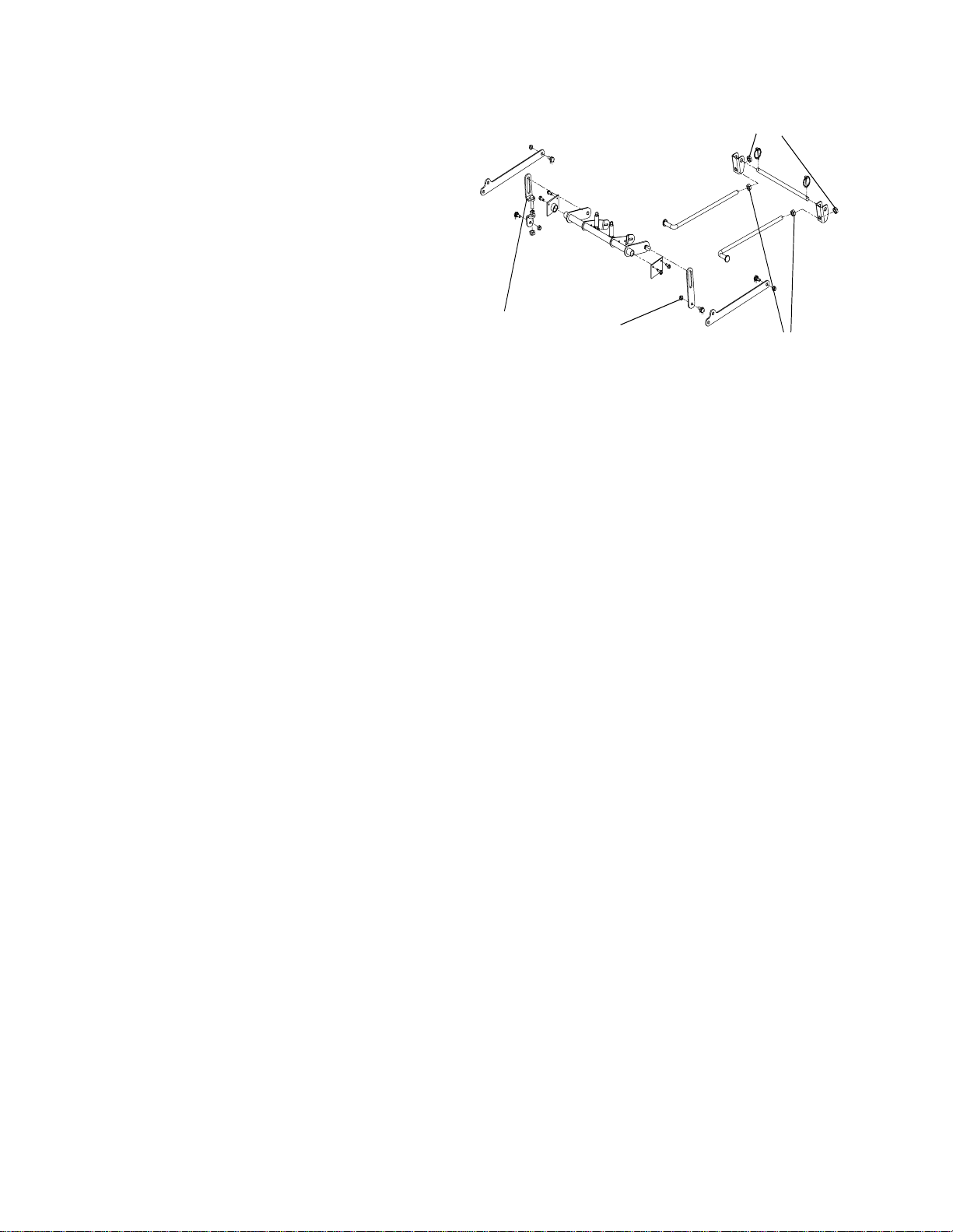
3. Check the right and left rear Driv e tire pressur e.
Adjust as necessary to 8-10 psi.
4. Measure blade-to-ground hei ght at the front tip
of the right blade. To obtain an accurate measure, al i gn blades in p arallel with mo wer centerline, (i.e. front to back).
5. Measure blade-to-ground hei ght at the front tip
of the left blade. Be sure to measure at t he
blade t ip with the blades arranged in proper
position.
6. To lev e l the deck, (side to side) adj ust t he
threaded link a t the left side of t he deck (P oint B)
so that the blade-t o-groun d heig ht at the right
front blade t ip matches that o f the left front blad e
tip. T hi s i s done by loos eni ng the jam nuts on
the threaded link and tighten ing the low er nut to
raise the dec k and l oosening the nut to lo wer the
deck.
7. Measure t he blade-to-ground height at the rig ht
rear blade tip. Again be sure to measure at the
blade t ip at the rear of the right blade when
aligned along the mower c ente rline. The bladeto-ground heig ht at the rear of the blade tip
should be 1/8" to 1/4” higher than the front tip .
This is refer red to as blade pitc h. The same
height difference should b e true for the lef t
blade, m easured front and back.
8. To adjust the blade pitch, the deck pitch m ust be
adjusted. Loosen the inner jam nuts at the rear
of the horizontal threaded li nks. Start at Point C
to raise the rear of the deck , tighten the front
outer jam nut to raise t he front of the deck.
Adjust the rear jam nut a t Point C to take the
slack out of the threade d link.
9. The final adj ustment w ould be to ta ke the “slack”
out of the front linkage (P oint C) b y adjusting the
jam nuts on the threaded link. Loos en the jam
nuts and tighten the inner n ut to remo v e “slac k”.
10. In man y cases it will be necessary to adjust
deck hei ght using both e ye bolt ad justme nts and
pitch adjustment to achie v e the corr ect blade -toground h eig hts . If you rem ember that the front
right blade tip adjustment is fixed and y ou level
to that height, adjusting the dec ks will be simpli fied.
Point B
Figure. 12
Left Side
Jam Nuts
Front
of Unit
Point C
Right
Side
Point C
Jam Nut
26
Page 27
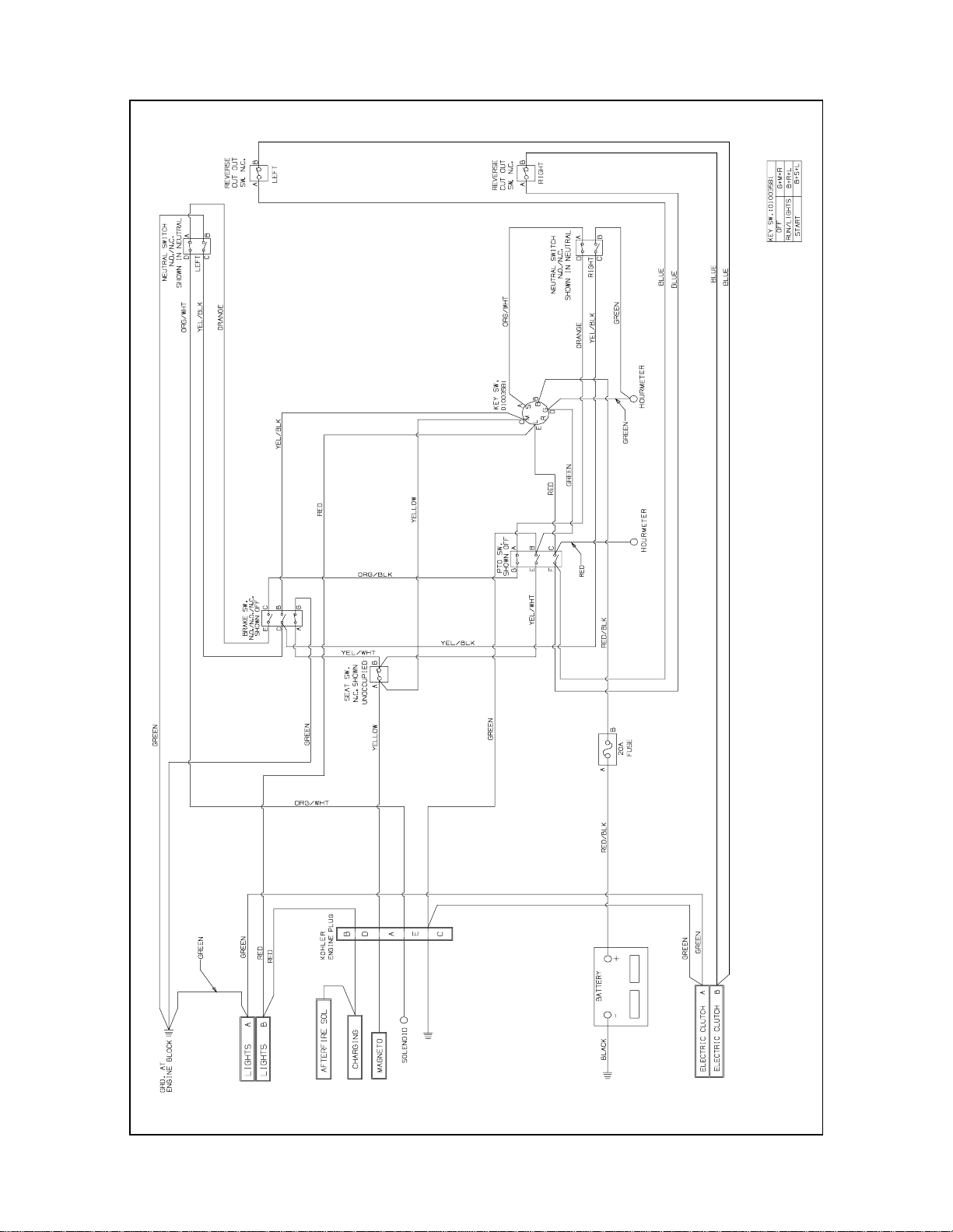
WIRING DIAGRAM
27
GD: 02000461
Page 28

SLOPE GAUGE
USE THIS PAGE AS A GUIDE TO DETERMINE SLOPES WHERE YOU MAY NOT OPERATE SAFELY.
Do not mow on inclines with a slope in exces s of 15 d egrees (a rise of approx imately 2-1/2 feet every 10 feet). A riding mower
could overturn and caus e serious injury. If operating a walk-behind m ower on such a slope, it is extremely difficult to maintain
your footing and you could slip, resulting in serious injury.
Operate ZERO-TURN mowers across the face of slopes, never up and down slopes.
Operate WALK-BEHIND mowers across the face of slopes, never up and down slopes.
F
O
L
D
O
N
D
O
T
T
E
RE
S
P
E
,
R
E
D
L
I
NE
SIGHT AND HOLD THIS LEVEL WITH A VERTICAL TREE
A POW ER POL E
A CORNER OF A BUILDING
OR A FENCE POST
WARNING
15°
NT
IN
G
A
1
5
°
S
L
O
P
E
28
Page 29

MAINTENANCE RECORD
DATE WORK PERFORMED DATE WORK PERFORMED
29
Page 30

MAINTENANCE RECORD
DATE WORK PERFORMED DATE WORK PERFORMED
30
Page 31

MAINTENANCE RECORD
DATE WORK PERFORMED DATE WORK PERFORMED
31
Page 32

MANUFA CTURER’S LIMITED WARRANTY FOR:
TWO-YEAR RESIDENTIAL
ONE-YEAR COMMERCIAL
Proper maintenance of your Cub Cadet equipment is the owner’s responsibility. Follow the instructions in
your operator’s manual for correct lubricants and maintenance schedule. Your Cub Cadet dealer carries a
complete line of quality lubricants and filters for your equipment’s engine, transmission, chassis and
attachments.
Riding mowers, lawn tractors, garden tractors, utility vehicles,
Cub Cadet attachments and home maintenance products
This limited warranty for residential users, covers any defect in materials or workmanship in your Cub
Cadet equipment for two years from the date of purchase for the first user purchaser. We will replace or
repair any part or parts without charge through your authorized Cub Cadet dealer.
Batteries have a one-year prorated limited warranty with 100% replacement during the first three months.
V-belts for either the traction drive or any attachment s are covered for one year only.
Cub Cadet equipment used commercially is warranted for one year only.
(Commercial use is defined as either having hired operators or used for income producing purposes.)
Items not covered
The warranty does not cover routine maintenance items such as lubricants, filters (oil, fuel, air and hydraulic), cleaning, tune-ups, brake and/or clutch inspection, adjustments made as part of normal mainten ance,
blade sharpening, set-up, abuse, accidents and normal wear. It does not cover incidental costs such as
transporting your equipment to and from the dealer, telephone charges or renting a product temporarily to
replace a warranted product.
There is no other express warranty.
How to obtain service
Contact your authorized Cub Cadet servicing dealer who sold you your Cub Cadet equipment. If this
dealer is not available, see the Consumer Yellow Pages under “lawn mowers” for the name of a dealer
near you.
If you need further assistance in finding an authorized Cub Cadet servicing dealer, contact:
Cub Cadet LLC
Post Office Box 361131
Cleveland, Ohio 44136-01 19
Phone: 877-282-8684
How does state law apply?
This limited warranty gives you specific legal rights, and you may also have other rights which vary from
state to state.
Form No. 02000457 Rev. 04-1 10/28/2004
 Loading...