

Page 1

Parts Manual
(10/98)
Models
Z-48, Z-54
Z-54L
IMPORTANT: READ SAFETY RULES AND INSTRUCTIONS CAREFULLY
Warning: This unit is equipped with an internal combustion engine and should not be used on or near any unimproved forest-
covered, brush-covered or grass-covered land unless the engine’s exhaust system is equipped with a spark arrester meeting
applicable local or state laws (if any). If a spark arrester is used, it should be maintained in effective working order by the operator.
In the State of California the above is required by law (Section 4442 of the California Public Resources Code). Other states may have
similar laws. Federal laws apply on federal lands. A spark arrester for the muffler is available through your nearest engine authorized
service dealer or contact the service department, P.O. Box 368023 Cleveland, Ohio 44136-9722.
CUB CADET CORP. P.O. BOX 368023 CLEVELAND, OHIO 44136-9722
PRINTED IN U.S.A.
FORM NO. 770-10100
Page 2
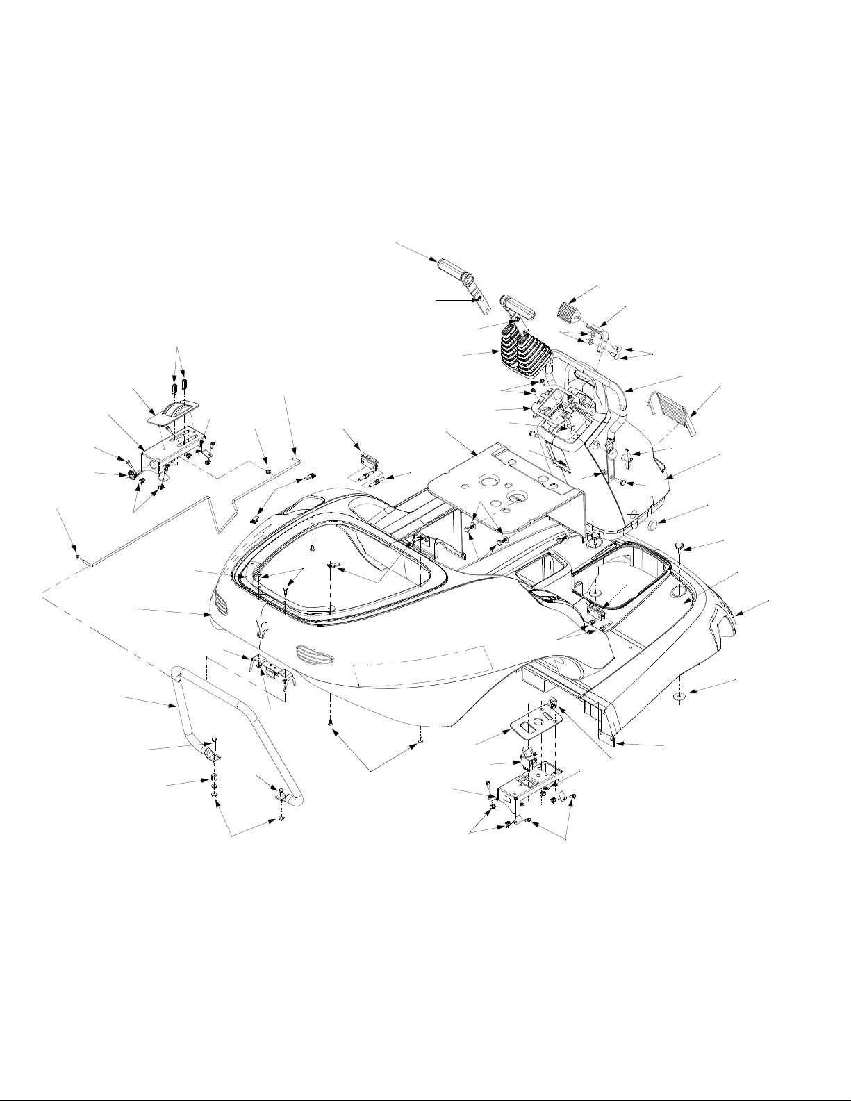
Models Z-48, Z-54, & Z-54L
1
2
5
6
40
11
38
37
45
36
39
42
35
41
34
43
33
44
32
30
31
26
30
27
16
3
4
11
12
13
29
28
14
27
7
8
9
10
15
17
18
26
19
20
21
53
22
23
46
47
15
48
49
2
52
39
50
51
11
34
24
25
Page 3

REF.
NO.
1 731-3263 Control Handle
2 710-0451 Carriage Bolt 5/16-18 x .75
3 712-3004A Flange Lock Nut 5/16-18
4 731-3185 Control Bellow
5 735-0251 Foot Pad
6 703-2807B Foot Pad Mounting Bracket
7 712-0431 Flange Lock Nut 3/8-16
8 710-3168 Carriage Bolt 3/8-16
9 749-3081 Cruise Control Tube
10 731-3128A Lens
11 710-0642 Hex Washer Screw 1/4-20 x .75
12 703-2648 Bellow Retainer Bracket
13 710-0276 Carriage Screw 5/16-18 x 1.0
14 703-3288 Control Tube Mounting Bracket
15 712-3004A Flange Lock Nut 5/16-18
16 731-3264 Seatbase Cover
17 720-0241 Wingnut Knob Assembly 5/16-18
18 738-0754 Shoulder Screw
19 731-3284 Console
20 726-0289 Plug
21 738-3163A Shoulder Screw 3/8-16 x .75
22 731-3286 Body
23 736-3039 Flat Washer .406 ID x 1.5 OD
24 603-0578 Body Plate Assembly
25 703-1345A Key
26 703-2928 Body Hinge
27 710-0376 Hex Cap Screw 5/16-18 x 1.0
PART
NO. DESCRIPTION
REF.
NO.
28 738-0296 Shoulder Screw
29 736-0226 Flat Washer .474 ID x .879 OD
30 712-0185 U-Type Nut 1/4-20
31 710-3015 Hex Cap Screw 1/4-20 x .75
32 747-3303 Support Rod
33 732-0830 Clip
34 726-3047 Push Nut
35 720-0302 Lever Knob
36 731-3195A Control Panel Cover - LH
37 603-0424 Control Panel Assembly - LH
38 723-3042 Snap Bushing
39 712-0453 Retainer Nut 1/4-20
40 726-0106 Cap Nut
41 703-3078 Latch Mounting Plate
42 731-3187 Rear Body
43 603-0643 Clip Spring Bracket Assembly
44 712-3027 Lock Nut 1/4-20
45 749-3082 Engine Tube Support
46 710-3180 Hex Cap Screw 5/16-18 x 1.75
47 750-3200 Spacer
48 710-3078 Hex Cap Screw 5/16-18 x 1.0
49 710-0946 Screw 1/4-20 x .625
50 731-3196 Cover Panel - RH
51 725-3233 Electric Switch PTO
52 603-0425 Control Panel Assembly - RH
53 735-0259 Floor Pad LH
PART
NO. DESCRIPTION
735-0260 Floor Pad RH
3
Page 4
Models Z-48, Z-54, & Z-54L
20
2
3
4
7
13
6
12
4
6
1
5
9
8
10
11
14
17
21
16
15
18
6
19
22
23
4
Page 5

REF.
NO.
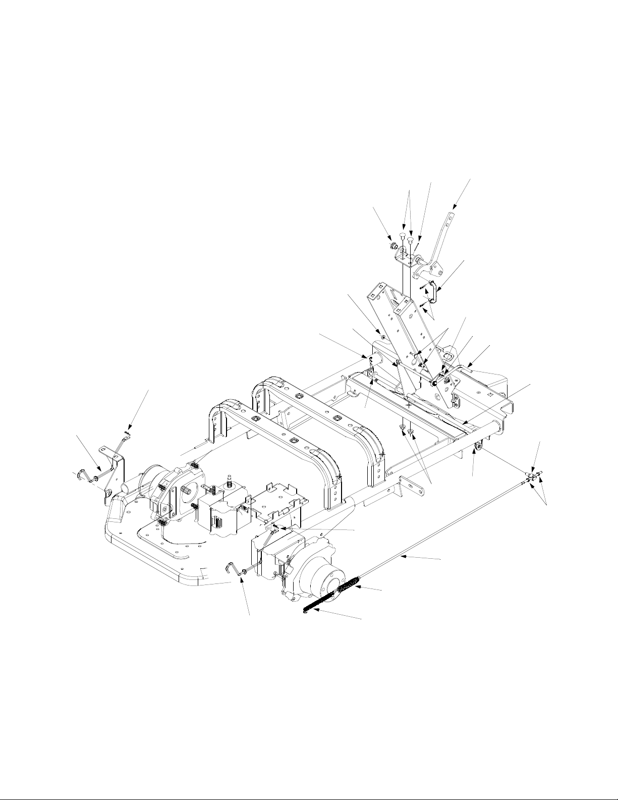
1 603-0649 Parking Brake Shift Ass’y
2 714-3004 Cotter Pin
3 710-3178 Carriage Bolt 3/8-16 x .75
4 741-0324 Hex Flange Bearing .506 ID x .590
5 747-3404 Connecting Brake Rod
6 714-0104 Cotter Pin
7 712-3027 Hex Flange Lock Nut 1/4-20
8 710-0134 Carriage Screw 1/4-20 x .62
9 703-2857 Retaining Rod Bracket
10 732-0827 Torsion Spring 5/16
11 747-3397 Parking Brake Retaining Rod
12 703-3405 Support Plate
13 714-0101 Cotter Pin
14 603-0683 Brake Rod Ass’y
15 736-0258 Flat Washer .385 ID x 1.0 OD
16 712-0431 Flange Lock Nut 3/8-16
17 711-3357 Ferrule
18 712-0314 Jam Nut 1/4-28
19 747-3266A Bracket Rod
20 747-3363 Release Pump Rod LH
21 747-3284 Release Pump Rod RH
22 732-0463 Extension Spring
23 732-0800 Extension Spring
PART
NO. DESCRIPTION
5
Page 6
Models Z-48, Z-54, & Z-54L
19
9
21
23
14
16
33
8
25
27
5
9
25
27
14
37
33
26
33
1
33
15
10
17
15
17
21
15
21
7
20
36
24
12
14
9
11
10
17
15
28
9
17
6
20
36
23
24
12
21
9
31
2
19
15
19
22
30
15
10
33
9
9
3
33
26
33
4
33
15
18
34
13
32
22
11
29
35
21
13
15
21
18
6
19
Page 7

REF.
NO.
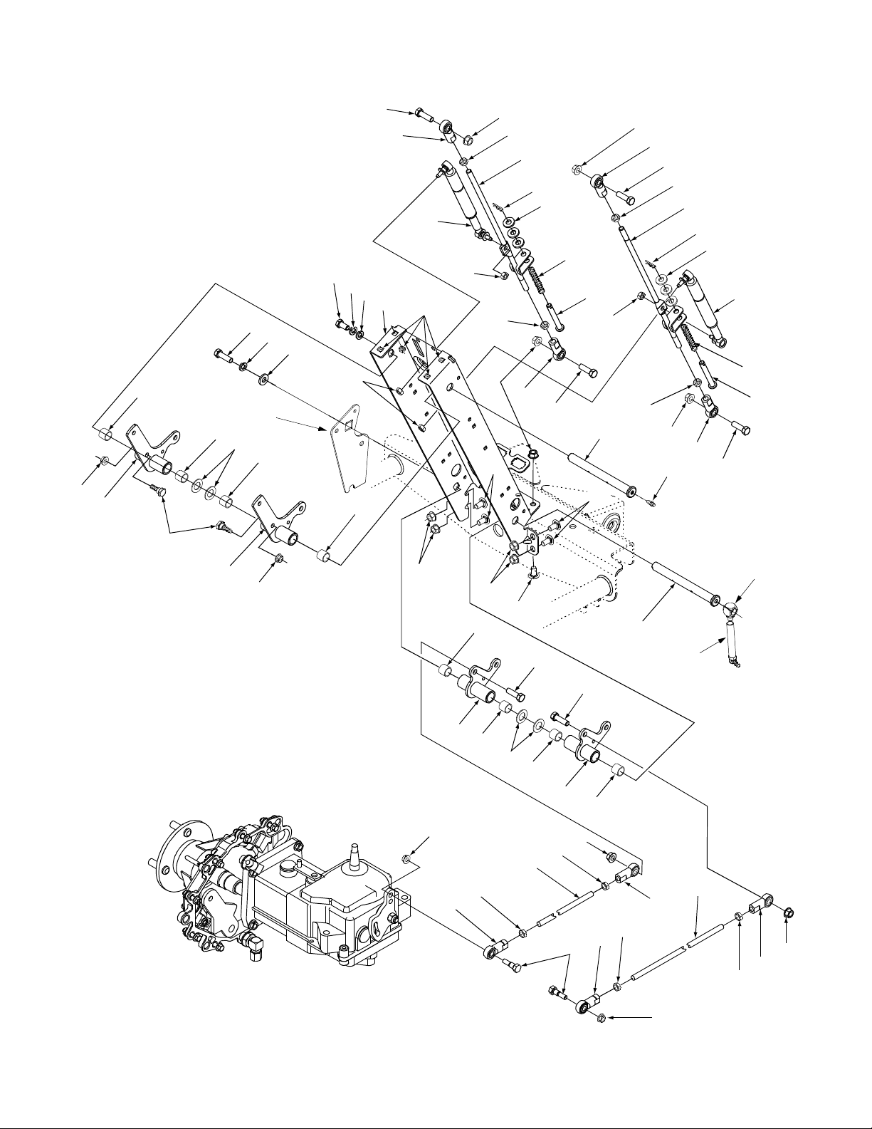
1 603-0340 Bellcrank Ass’y Upper LH
2 603-0341 Bellcrank Ass’y Upper RH
3 603-0342 Bellcrank Ass’y Lower LH
4 603-0343 Bellcrank Ass’y Lower RH
5 603-0647 Support Ass’y Tower
6 603-0410 Rod Ass’y Control RH
7 603-0411 Rod Ass’y Control LH
8 710-0216 Hex Cap Screw 3/8-16 x .75
9 710-3005 Hex Cap Screw 3/8-16 x 1.25
10 710-3178 Carriage Bolt 3/8-16 x .75
11 711-1111 Control Shaft
12 711-1124 Pin
13 712-0312 Hex Jam Nut LH 3/8-24
14 712-0365 Hex Center Lock Nut
15 712-0431 Hex Flange Lock Nut 3/8-16
16 712-0453 Retainer 1/4-20
17 712-0711 Hex Jam Nut 3/8-24
18 712-3001 Hex Jam Nut 3/8-24
19 712-3004A Hex Flange Lock Nut 5/16-18
PART
NO. DESCRIPTION
REF.
NO.
20 714-0104 Cotter Pin
21 723-0420 Spherical Rod End RH 3/8-24
22 723-0421 Spherical Rod End LH 3/8-24
23 727-3113 Damper Cylinder
24 732-3084 Spring Compression
25 736-0169 Lock Washer 3/8
26 736-0539 Thrust Washer .625 ID x 1.12 OD
27 736-3004 Flat Washer .406 ID x .875 OD
28 737-0280 Grease Fitting
29 737-3072 Grease Fitting w/Tube
30 737-3073 Adapter 1/4-20
31 738-0296 Shoulder Bolt .437 Dia. x .268
32 738-3153 Shoulder Bolt
33 741-3063 Sleeve Bearing
34 747-3281 Control Rod LH 31-5/8
35 747-3282 Control Rod RH 35-3/8
36 736-0300 Flat Washer .406 ID x .87 OD
37 703-3405 Support Plate
PART
NO. DESCRIPTION
7
Page 8
Models Z-48, Z-54, & Z-54L
27
26
25
63
66
61
63
62
65
62
64
22
21
20
44
19
18
14
12
13
3
5
6
1
4
7
11
12
13
2
8
9
10
33
34
30
32
35
31
29
28
36
37
34
24
39
40
41
23
38
42
43
44
42
45
15
47
16
46
9
49
48
52
51
50
37
17
53
54
55
56
57
58
59
60
8
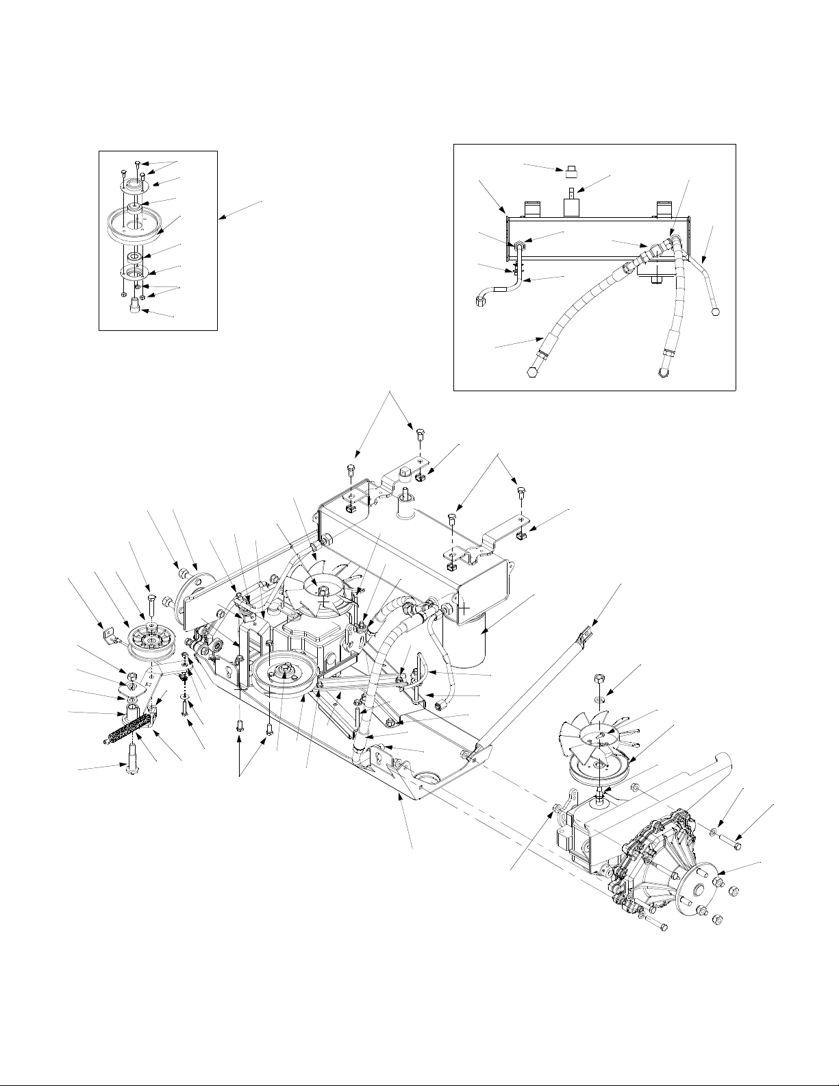
Page 9

REF.
NO.
1 737-3069 Pipe Plug
2 737-3070A Pipe Dipstick
3 603-0639 Hydraulic Tank Assembly
4 727-3116 Connection Fitting
5 721-0223 Seal
6 738-0940 Drain Plug
7 727-3120 Inlet Tube LH
8 727-3155 Tee Fitting
9 727-3154 Outlet Hose RH
10 727-3121 Inlet Tube RH
11 727-3153 Outlet Hose LH
12 710-0216 Hex Cap Screw 3/8-16 x .75
13 712-0455 Retainer Nut 3/8-16
14 747-3360 Belt Retainer Rod RH
15 710-0378 Hex Cap Screw 5/16-18 x 2.5
16 736-3089 Flat Washer 5/16
17 723-3071 Filter Element
18 731-1449A Fan Blade
19 712-0333 Hex Nut 1/2-20
20 703-3168 Mounting Pulley Bracket
21 756-0625 Roller Cable
22 738-0924 Hex Shoulder Screw 1/4-28 x .375
23 703-3169 Retainer Cable Bracket
24 712-0117 Lock Nut 1/4-28
25 618-3165 Complete Transmission Assembly LH
26 712-3050 Lug Nut
27 710-0347 Hex Cap Screw 3/8-16 x 1.75
28 736-0258 Flat Washer .385 ID x 1.0 OD
29 756-0627 Flat Idler Pulley 3.5 OD
30 703-3174 Mounting Bracket Cable
31 712-3019 Hex Nut 7/16-14
32 736-0171 Lock Washer 7/16
33 736-3015 Flat Washer .469 ID x .875 OD
PART
NO. DESCRIPTION
REF.
NO.
34 603-0377A Idler Arm Assembly
35 603-0102 Shoulder Screw
36 732-0478 Extension Spring 6.12 Lg
37 712-0431 Flange Lock Nut 3/8-16
38 712-0138 Hex Nut 1/4-28
39 736-0329 Lock Washer 1/4
40 736-0342 Flat Washer .283 ID x .75 OD
41 710-0428 Hex Cap Screw 1/4-28 x 1.25
42 710-3008 Hex Cap Screw 5/16-18 x .75
43 710-3011 Hex Cap Screw 3/8-16 x 2.25
44 603-0362 Idler Pulley Assembly 5.0”
45 703-2888 Idler Bracket
46 712-3004A Flange Lock Nut 5/16-18
47 710-3103 Hex Cap Screw 5/16-18 x 2.0
48 727-3100 Connection Fitting 1/2 x 3/8
49 603-0358B Skid Plate Assembly
50 747-3361 Belt Rod LH
51 603-0450 Support Pump Assembly
52 710-3178 Carriage Bolt 3/8-16 x .75
53 749-3040 Frame Strut
54 736-0921 Lock Washer 1/2
55 710-1189 Hex Washer Screw #12-24 x .625
56 756-0974 Transmission Pulley
57 732-0729 Wire Ring
58 736-0185 Flat Washer
59 710-3144 Hex Cap Screw 3/8-16 x 2.0
60 618-3164 Complete Tranmission Assembly RH
61 710-0751 Hex Cap Screw 1/4-20 x .62
62 703-2907 Bearing Cup
63 741-0600 Ball Bearing
64 756-3085 Idler Pulley 5.0”
65 712-0324 Hex Lock Nut 1/4-20
66 750-3176 Idler Spacer
PART
NO. DESCRIPTION
9
Page 10
Models Z-48, , Z-54, & Z-54L
1
4
7
6
3
2
8
2
5
REF.
NO.
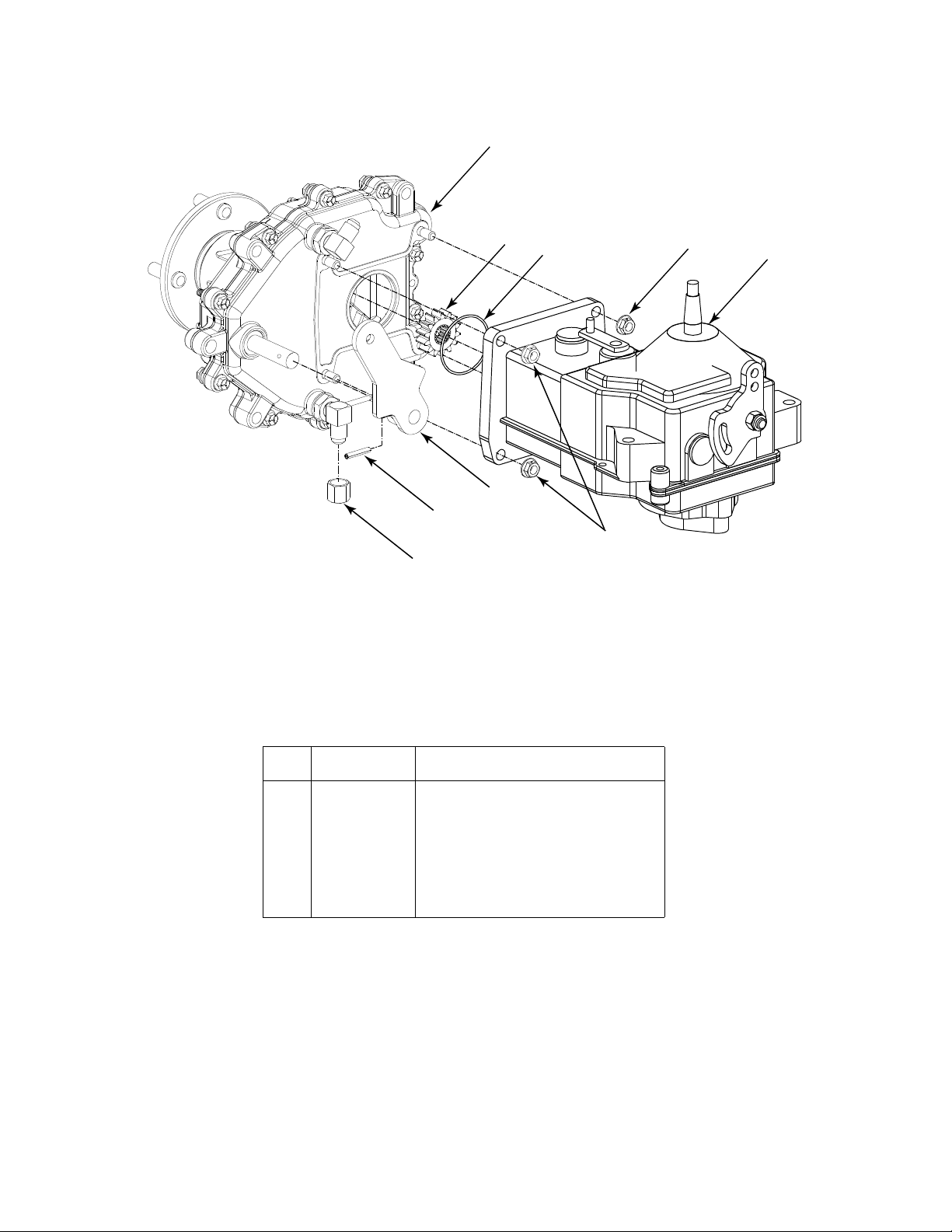
1 618-3110A Drive Ass’y Complete
2 712-3004A Hex Flange Lock Nut 5/16-18
3 715-0136 Spirol Pin 3/16 x 1.25
4 717-3396 Spur Gear 14T
5 717-3455 Hydro Transmission
6 718-3053 Parking Brake Lever
7 721-0343 O-Ring 2.0 Dia.
8 727-3125 Cap Nut 3/8
PART
NO. DESCRIPTION
10
Page 11
Models Z-48, Z-54, Z-54L
3
4
7
1
16
18
5
8
5
17
21
5
5
18
6
REF.
NO.
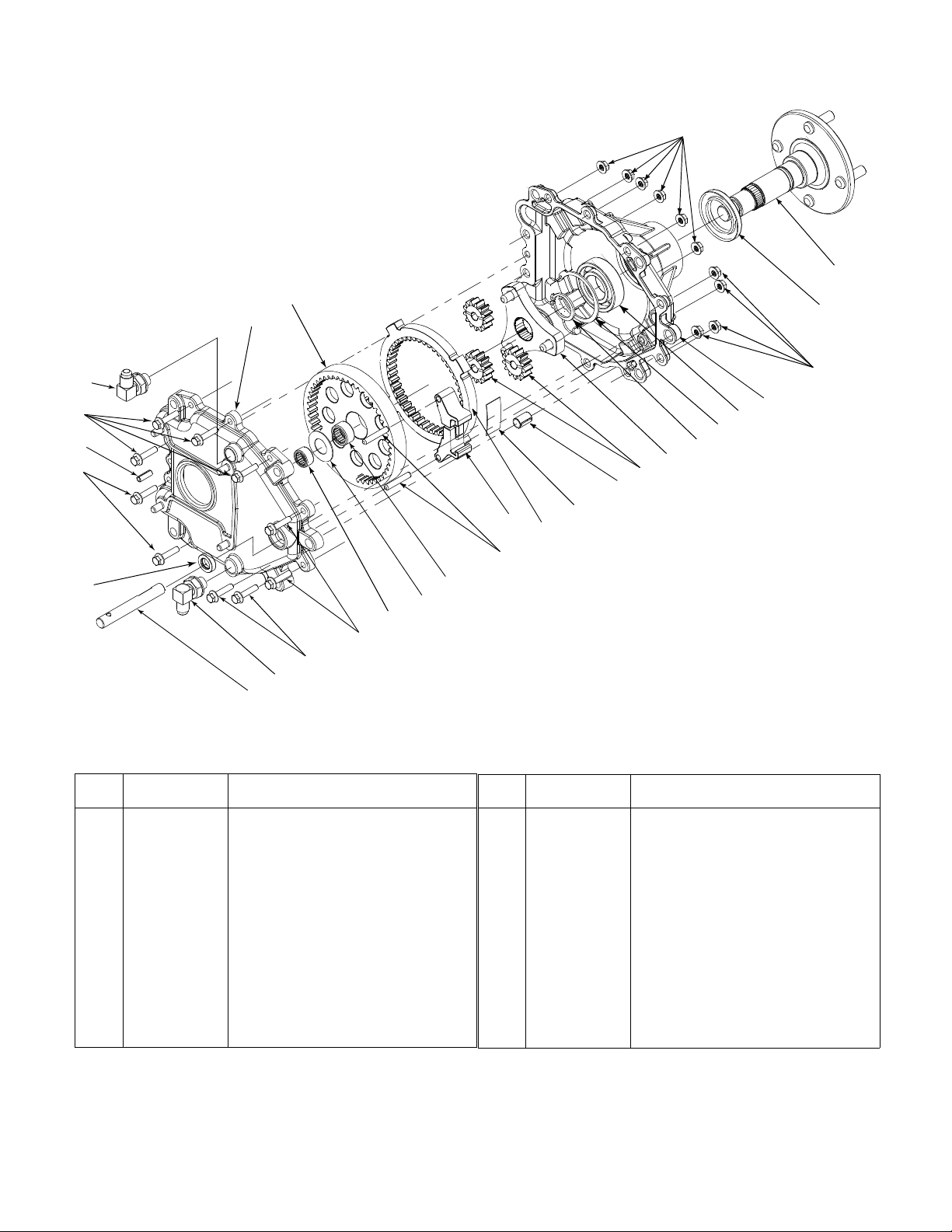
1 611-3012 Axle Assembly
2 618-3106 Carrier Assembly, Output
3 618-3107 Gear Assembly, 51T Internal & 20T
4 618-3109 Housing Ass’y
5 710-1342 Hex Washer Screw 1/4-20 x 1-1/8
6 711-1048 Brake Shaft
7 712-3027 Hex Flange Lock Nut 1/4-20
8 715-0156 Roll Pin
9 715-0219 Dowel Pin
10 715-3045 Bushing
11 716-3015 Inverted Retaining Ring
12 716-3018 Snap Ring
PART
NO. DESCRIPTION
618-3110A Drive Ass’y Complete
710-0852 Ribbed Neck Stud
20
23
15
22
11
12
2
13
10
24
9
REF.
NO.
13 717-3395 Spur Gear 13T
14 717-3397 Ring Gear 46T
15 719-3114 Axle Outer Housing
16 721-0381 Oil Seal
17 721-0393 Oil Seal
18 727-3124 Elbow Fitting
19 732-0752 Brake Shoe Spring
20 736-0351 Shim Washer .76 x 1.5 x .030
21 741-0665 Needle Bearing
22 741-3033A Ball Bearing
23 741-3080 Needle Bearing
24 761-3049 Shoe Brake
19
14
PART
NO. DESCRIPTION
736-0492 Shim Washer .76 x 1.5 x .010
736-0493 Shim Washer .76 x 1.5 x .020
7
11
Page 12

Models Z-48, Z-54, & Z-54L
19
21
18
20
17
31
49
32
30
35
34
33
7
4
5
6
8
1
42
28
29
25
26
50
9
10
23
49
24
11
12
13
14
15
3
27
51
22
16
35
47
41
38
48
37
36
39
40
2
44
43
45
46
12
Page 13

REF.
NO.
1 HG-70304 Housing Ass’y Upper
2 HG-50301 Lower Housing
3 HG-70299 Center Section Assembly
4 HG-9008000-0128 Lip Seal
5 HG-2003018 Spacer
6 HG-2003016 Wire Retaining Ring
7 HG-2003052 Retaining Ring
8 HG-2003043 Ball Bearing
9 HG-2003023 Cradle Bearing
10 HG-2003087 Variable Swashplate
11 HG-50551 Thrust Bearing
12 HG-50303 Input Shaft
13 HG-2003017 Block Thrust Washer
14 HG-2003014 Block Spring
15 HG-70079 Cylinder Block Assembly
16 HG-70082 Cylinder Block Assembly
17 HG-50304 Output Shaft (Motor)
18 HG-50552 Thrust Bearing
19 741-0361 Ball Bearing
20 HG-2000022 Wire Retaining Ring
21 HG-50329 Retaining Ring
22 HG-50649 Motor Bearing Retaining
23 HG-2000015 Slot Guide
24 HG-2003005 Trunnion Arm
25 HG-9008000-0126 Lip Seal
PART
NO. DESCRIPTION
717-3455 Transmission Ass’y Hydro
REF.
NO.
26 HG-45007 Control Arm
27 712-0237 Hex Lock Nut 5/16-24
28 HG-50426 Short Stud 5/16-24
29 HG-50281 Friction Puck
30 HG-2003554 Bypass Plate
31 HG-2003555 Bypass Actuator
32 HG-45074 Lip Seal
33 HG-50270 Bypass Arm
34 HG-44870 Retaining Ring
35 HG-50002 Pin
36 HG-50016 Screw
37 HG-2000029 Charge Relief Spring
38 HG-9001214-2500 Ball
39 HG-50578 O-Ring
40 HG-50331 Gasket
41 HG-44876 Self Tapping Screw
42 HG-9005110-8700 Drain Plug
43 HG-50273 Gerotor Assembly
44 HG-9004101-1340 O-Ring
45 HG-50260 Gerotor Cover
46 HG-50095 Screw
47 HG-50651 Relief Plate
48 HG-50653 Screw
49 HG-50650 Retaining Ring
50 736-0371 Washer
51 HG-50018 Set Screw
PART
NO. DESCRIPTION
13
Page 14

Models Z-48 & Z-54
16
17
18
21
24
14
15
20
19
23
26
28
25
29
11
22
1
7
8
9
6
4
12
13
27
30
2
3
4
10
5
31
37
34
35
40
32
33
36
38
39
14
Page 15

REF.
NO.
1 710-3009 Screw #10-24 x .750
2 746-3070 Throttle Control Cable 40.5”
3 746-3066 Choke Control Cable 38.0”
4 712-0161 Lock Nut #10-24
5 725-1711 Retainer Clip
6 710-3008 Hex Cap Screw 5/16-18 x .75
7 726-3008 Cable Clip Heat Shield
8 712-3004A Hex Lock Nut 5/16-18
9 749-3048 Fuel Line
10 736-0607 Lock Washer 5/16
11 726-0205 Hose Clamp
12 751-0535 Fuel Line Hose
13 710-3144 Hex Cap Screw 3/8-16 x 2.0
14 712-0431 Flange Lock Nut 3/8-16
15 751-3141 Oil Drain Hose
16 723-0454 Gasket Foam Seal Ring
17 751-3142 Oil Drain Cap
18 751-3140 Oil Drain
19 751-3147 Muffler Exhaust Clamp
20 749-3083 Exhaust
PART
NO. DESCRIPTION
REF.
NO.
21 749-3061 Lower Bumper Tube
22 712-3004A Hex Flange Lock Nut 5/16-18
23 736-0451 Shoulder Washer .320 ID x .93 OD
24 710-1174 Carriage Bolt 5/16-18 x 2.0
25 749-3062 Upper Bumper Tube
26 736-0258 Flat Washer .385 ID x 1.0 OD
27 603-0317 Clutch Retainer Ass’y
28 747-3362 Rear Belt Retainer Rod
29 736-3010 Flat Washer .407 ID x .812 OD
30 710-1007 Hex Washer Screw 3/8-16 x 1.5
31 710-1008 Hex Washer Screw 3/8-16 x 1.875
32 736-0250 Flat Washer 1.0 ID x 1.75 OD
33 754-3076 V-Belt
34 756-3060 Drive Pulley
35 714-0128 Key
36 725-0157 Cable Tie
37 717-3389 Electric PTO Clutch
38 750-3106 Spacer Clutch
39 736-0171 Lock Washer 7/16
40 710-3157 Hex Cap Screw 7/16-20 x 3.25
PART
NO. DESCRIPTION
15
Page 16

Model Z-54L
22
23
13
14
21
16
15
18
1
2
3
11
17
29
10
6
12
20
26
9
12
27
5
4
3
8
7
10
19
24
25
24
33
36
38
28
30
31
32
34
35
37
39
16
Page 17

REF.
NO.
1 710-3009 Screw #10-24 x .750
2 746-3068 Choke Control Cable 43.0”
3 712-0161 Nylon Lock Nut #10-24
4 746-3071 Throttle Control Cable 53.0”
5 751-3141 Oil Drain Hose
6 723-0473 Foam
7 710-0216 Hex Cap Screw 3/8-16 x .75
8 751-0535 Fuel Line Hose
9 726-0205 Hose Clamp
10 726-3008 Heat Shield Cable Clip
11 736-0607 Lock Washer 5/16
12 712-3004A Flange Lock Nut 5/16-18
13 710-3008 Hex Cap Screw 5/16-18 x .75
14 703-3023 Mounting Muffler Bracket
15 749-3062 Upper Bumper Tube
16 749-3061 Lower Bumper Tube
17 710-3144 Hex Cap Screw 3/8-16 x 2.0
18 712-0431 Flange Lock Nut 3/8-16
19 736-3010 Flat Washer .407 ID x .812 OD
20 736-0451 Shoulder Washer .320 ID x .93 OD
21 710-1174 Carriage Bolt 5/16-18 x 2.0
22 749-3074A Muffler Tube
PART
NO. DESCRIPTION
REF.
NO.
23 751-3151 Muffler Tube Clamp
24 726-0290 Adjustable Clamp
25 703-3014 Muffler Shield
26 736-0258 Flat Washer .385 ID x 1.0 OD
27 736-0159 Washer 5/16
28 747-3362 Rear Belt Retainer Rod
29 603-0317 Clutch Retainer Ass’y
30 736-0242 Bell Washer .340 ID x .872 OD
31 710-3207 Hex Cap Screw
32 754-3077 V-Belt
33 756-3083 Pulley
34 714-0128 Key 1/4 x 1.0
35 725-0157 Cable Tie
36 717-3390 Electric PTO Clutch
37 750-3106 Spacer Clutch
38 736-0171 Lock Washer 7/16
39 710-1616 Hex Cap Screw
PART
NO. DESCRIPTION
17
Page 18

Models Z-48 & Z-54
40
26
13
13
14
6
17
4
9
19
Black- From
Battery Negative
Red- From
Battery Positive
To Engine
Red- To Starter
Black- To Engine Ground
Green- To Ground
31
To PTO
37
20
Red/Black- From
Battery Positive
30
34
2
24
15
42
10
28
23
12
32
5
36
16
28
25
35
33
16
7
3
38
22
21
11
41
29
12
8
1
15
18
18
27
Page 19

REF.
NO.
1 629-3033 Main Wire Harness
2 629-3034 Engine Wire Harness - Inc 19,24,26 & 31
3 703-1345A Ignition Key
4 703-2809 Indicator Bulb Mounting Bracket
5 703-2836 Headlight Mounting Bracket
6 703-3149 Battery Retainer Strip
7 710-0134 Carriage Bolt 1/4-20 x .62
8 710-0425 Machine Screw #10-24 x 5/8
9 710-3013 Hex Cap Screw 1/4-20 x .50
10 710-3015 Hex Cap Screw 1/4-20 x .75
11 710-3143 Pan Head Cutting Screw #10-24
12 712-0161 Hex Insert Lock Nut #10-24
13 712-0271 Hex Sems Nut 1/4-20
14 712-0397 Nylon Wing Nut 1/4-20
15 712-0431 Hex Flange Lock Nut 3/8-16
16 712-3027 Hex Flange Lock Nut 1/4-20
17 723-0455 Indicator Light Foam Protector
18 725-0157 Cable Tie
19 725-0340 Battery Terminal Cover - Black
20 725-1722 Battery
21 725-1346 Ignition Switch Nut 5/8-32
PART
NO. DESCRIPTION
REF.
NO.
22 725-1347 Ignition Switch Cap
23 725-1365 Indicator Bulb
24 725-1656 Mini 20 Amp Fuse
25 725-1718 Relay
26 725-3007A Battery Terminal Cover - Red
27 725-3163 Ignition Switch
28 725-3164A Plunger Safety Switch
29 725-3229 Hourmeter/Tachometer
30 725-3233 PTO Switch
31 725-3237 Terminal Cover - Red
32 725-3250 Headlight Ass’y
33 725-3251 Voltage Sensor
34 725-3253 Seat Switch
35 726-0349 Ratcheet Retainer
36 731-3184 Headlight Bezel
37 731-3233 Battery Tray
38 732-0816 Switch Mounting Spring
40 747-3347 Battery Retainer Rod
41 750-0539 Spacer
42 783-0462 PTO Switch Retainer Bracket
PART
NO. DESCRIPTION
759-3864 Headlight Bulb
19
Page 20

Model Z-54L
16
16
33
49
18
9
23
7
12
Black-Battery Negative
Red-
Battery
Positive to Solenoid
Voltage Regulator
To Starter
Red to Starter
Solenoid
Green-To Ground
Black-To Engine Ground
37
To PTO
To Engine
25
47
43
30
14
31
41
26
3
36
6
2
40
50
39
44
28
21
10
11
27
24
29
38
8
42
21
35
15
1
20
34
Page 21

REF.
NO.
1 629-3032 Main Wire Harness
2 629-3035 Engine Wire Harness - Inc 30
3 725-3191A Plunger Safety Switch
6 759-3476A Ignition Key
7 703-2809 Indicator Bulb Mounting Bracket
8 703-2836 Headlight Mounting Bracket
9 703-3149 Battery Retainer Strip
10 710-0134 Carriage Bolt 1/4-20 x .62
11 710-0425 Machine Screw #10-24 x 5/8
12 710-3013 Hex Cap Screw 1/4-20 x .50
14 710-3015 Hex Cap Screw 1/4-20 x .75
15 712-0161 Hex Insert Lock Nut #10-24
16 712-0271 Hex Sems Nut 1/4-20
18 712-0397 Nylon Wing Nut 1/4-20
21 712-3027 Hex Flange Lock Nut 1/4-20
23 723-0455 Indicator Light Foam Protector
24 725-0157 Cable Tie
25 725-0340 Battery Terminal Cover - Black
26 722-1722 Battery
27 725-1346 Ignition Switch Nut 5/8-32
PART
NO. DESCRIPTION
REF.
NO.
28 725-1347 Ignition Switch Cap
29 725-1365 Indicator Bulb
30 725-1656 Mini 20 Amp Fuse
31 725-1718 Relay
33 725-3007A Battery Terminal Cover - Red
34 725-1717 Ignition Switch
35 725-3164A Plunger Safety Switch
36 725-3233 PTO Switch
37 725-3237 Terminal Cover - Red
38 725-3250 Headlight Ass’y
39 725-3251 Voltage Sensor
40 725-3254 Seat Switch
41 726-0349 Ratcheet Retainer
42 731-3184 Headlight Bezel
43 731-3233 Battery Tray
44 732-0816 Switch Mounting Spring
49 747-3347 Battery Retainer Rod
50 783-0462 PTO Switch Retainer Bracket
PART
NO. DESCRIPTION
759-3864 Headlight Bulb
21
Page 22

Models Z-48, Z-54, & Z-54L
3
20
6
14
15
17
12
16
1
5
19
10
9
11
16
8
7
6
14
12
15
12
2
17
18
23
21
22
13
4
REF.
NO.
1 603-0363 Bracket, Castor Wheel
2 603-0382 Axle Ass’y Front Inc. 12 & 17
3 603-0389A Pin Ass’y, Pivot
4 634-3163 Wheel Comp 11.0 x 4.0 x 5.0
5 710-0506 Screw, Hex Cap, 1/2-20 x 5.5
6 710-0514 Screw, Hex Cap, 3/8-16 x 1.0 GR5
7 710-3178 Bolt, Carriage, 3/8-16 x .75
8 712-0229 Push Nut, Retainer, 3/8 ID
9 712-0239 Nut, Hex Center Lock, 1/2-20
10 712-0431 Nut, Hex Flange Lock, 3/8-16
11 712-3075 Nut, Hex Lock, 1.0-14
12 731-0374 Bearing, Flange, 1.0 ID
PART
NO. DESCRIPTION
21
24
23
9
23
4
24
23
REF.
NO.
13 734-3179 Tire, Urethane, Only
14 736-0169 Washer, Lock 3/8
15 736-0227 Washer, Flat, .39 x 1.5 x .134
16 736-0274 Washer, Special Flat
17 737-0280 Fitting, Grease
18 737-3004 Fitting, Grease, 90° Tap 1/4-28
19 737-3072 Fitting, Grease, 65° w/Extension
20 737-3090 Adapter, 1/8 NPTF x 1/8 NPTF
21 741-3069 Bearing, Flange
22 741-3070 Bearing, Roller
23 750-0456 Spacer, .79 ID x .347 Lg ‘
24 750-3197 Spacer, Wheel
PART
NO. DESCRIPTION
12
16
1
5
22
Page 23

Models Z-48, Z-54, & Z-54L
1
23
16
11
17
2
3
2
6
8
7
9
10
12
15
18
20
22
4
5
13
14
10
19
21
REF.
NO.
1 757-3006 Seat Assembly
2 731-3154 Seat Slide
3 712-3004A Flange Lock Nut 5/16-18
4 732-3098 Spring Index
5 720-0190 Knob
6 603-0294 Bracket Assembly
7 738-0372 Shoulder Spacer
8 712-3005 Flange Lock Nut 3/8-16
9 710-1260A Hex Washer Screw 5/16-18 x .75
10 738-0296 Shoulder Screw
11 732-3080 Compression Spring 1.28 OD x 3.5
12 710-0520 Hex Cap Screw 3/8-16 x 1.5
PART
NO. DESCRIPTION
REF.
NO.
13 710-0347 Hex Cap Screw 3/8-16 x 1.75
14 736-0227 Flatwasher
15 603-0470 Seat Bracket Assembly
16 603-0318A Seat Spring Plate Assembly
17 738-3156 Shoulder Spacer
18 736-0314 Thrust Washer
19 732-0827 Torsion Spring
20 738-3166 Shoulder Spacer
21 714-0104 Cotter Pin
22 747-3342 Rod
23 757-3009 Seat Arm (Set of Two) Optional
PART
NO. DESCRIPTION
23
Page 24

Models Z-48, Z-54, & Z-54L
2
3
4
12
13
5
15
21
21
28
14
16
18
17
20
19
6
7
8
9
10
11
1
27
26
25
24
4
22
23
33
36
35
32
31
30
29
34
37
38
20
39
24
Page 25

REF.
NO.
1 711-0642A Handle Button
2 731-3158 Handle Deck Lift Grip
3 732-3097 Compression Spring
4 747-3405 Front Lift Rod
5 738-0507B Shoulder Screw .500 Dia x .434
6 710-0216 Hex Cap Screw 3/8-16 x .75
7 603-0422 Shaft Mounting Bracket - LH
8 603-0370 Pivot Link Bearing Ass’y
9 603-0313 Lift Shaft Ass’y
10 703-2621 Adjustable Deck Lift Link
11 703-2780 Lift Parallel Link
12 603-0327 Handle Bearing Ass’y
13 703-2772 Deck Height Adjustable Plate
14 738-3150 Lift Handle Shoulder Screw
15 712-3020 Top Lock Jam Nut 3/8-16
16 603-0423 Shaft Mounting Bracket - RH
17 710-3083 Hex Cap Screw 5/16-18 x 1.375
18 711-0773 Eye Bolt Adjustable Link
19 738-0380 Shoulder Screw 3/8-16
20 712-0206 Hex Nut 1/2-13
PART
NO. DESCRIPTION
REF.
NO.
21 712-0431 Flange Lock Nut 3/8-16
22 738-3151 Shoulder Screw 3/8-16 .56 x .27
23 712-3015 Jam Nut 5/8-11
24 736-0158 Lock Washer 5/8
25 712-3016 Lock Hex Nut 5/8-11
26 711-3266 Clevis Pin
27 703-3407 Front Lift Bracket
28 603-0401 Lift Arm Ass’y
29 738-0183 Shoulder Screw 3/8-16 .50 x .21
30 603-0257 Fork Lift Ass’y
31 710-3011 Hex Cap Screw 3/8-16 x 2.25
32 747-3276 Lift Link Rod
33 736-0300 Flat Washer .406 x .875
34 747-3267 Handle Arm
35 750-3200 Spacer .448 ID x .688 OD
36 712-0290 Lock Nut 7/16-14
37 712-3009 Hex Center L-Nut 5/16-18
38 710-0431 Hex Screw 3/8-16 x 1.50
39 737-0280 Grease Fitting
PART
NO. DESCRIPTION
25
Page 26

Models Z-48, Z-54, &Z-54L
22
12
6
3
9
20
9
10
6
14
31
1
14
13
30
15
29
2
25
11
5
10
26
16
21
8
6
18
4
19
13
13
23
24
22
22
28
7
13
7
22
27
22
28
REF.
NO.
1 603-0258B Frame
2 603-0424 Control Panel LH
3 603-0425 Control Panel RH
4 703-2783 Fuel Tank Mounting Bracket
5 710-0376 Hex Cap Screw 5/16-18 x 1.0
6 710-0642 Hex Washer Screw 1/4-20 x .625
7 710-0520 Hex Cap Screw 3/8-16 x 1.5
8 710-1174 Curved Carriage Screw 5/16-18 x 2.0
9 710-0216 Hex Cap Screw 3/8-16 x 3/4
10 710-0859 Hex Cap Screw 3/8-16 x 2.5
11 710-3180 Hex Cap Screw 5/16-18 x 1.75
12 712-0251 Retainer Nut 3/8-16
13 712-0431 Hex Flange Lock Nut 3/8-16
14 712-0453 Retainer Nut 1/4-20
PART
NO. DESCRIPTION
NOTE: For painted parts, please refer to
the list of color codes below. Please add the
applicable color code, wherever needed, to
the part number to order a replacement part.
For instance, if a part, numbered 700-xxxx,
is painted Cub Yellow, the part number to
order would be 700-xxxx-0498.
Cub Yellow: 0498
Cub Beige: 0499
Powder Black: 0637
REF.
NO.
15 712-0455 Retainer Nut 3/8-16
16 712-3004A Hex Flange Lock Nut 5/16-18
18 723-3042 Snap Bushing
19 728-0117 Pop Rivet
20 732-0830 Spring Clip
21 736-0451 Saddle Washer
22 736-3004 Flat Washer .406ID x .875 OD
23 749-3061 Lower Tube Bumper
24 749-3062 Upper Tube Bumper
25 749-3082 Engine Support Tube
26 750-3200 Spacer
27 603-0620 Front Bumper
28 726-0298 End Cap
PART
NO. DESCRIPTION
26
Page 27

Models Z-48, Z-54, & Z-54L
5
6
4
1
4
3
2
3
2
9
7
8
REF.
NO.
1 703-2783 Fuel Tank Mounting Bracket
2 710-0870 Hex Cap Screw 3/8-16 x .62
3 736-0169 Lock Washer 3/8
4 736-0227 Flat Washer .390 ID x 1.5 OD
5 751-3124B Fuel Cap
6 751-3143 Fuel Tank
7 634-3030 Rim Ass’y 8.0 x 6.19
8 734-0255 Tubeless Air Valve
9 734-3160 Tire 20.0 x 9.0 x 8.0
PART
NO. DESCRIPTION
27
Page 28

Model Z-48
43
37
42
54
5
44
41
7
45
14
40
20
1
3
4
5
8
9
10
12
7
46
17
18
19
47
7
41
52
53
13
21
61
48
50
40
7
11
49
60
15
16
9
51
62
40
2
6
5
14
37
68
26
7
67
7
66
7
22
23
24
41
55
34
20
21
63
58
35
64
65
39
36
7
38
41
7
27
28
29
73
69
25
70
53
72
30
31
32
71
33
41
56
52
57
59
58
28
Page 29

REF.
NO.
1 703-2817 LH Belt Cover
2 703-2816 RH Belt Cover
3 747-3306 Idler Spring Mounting Rod
4 738-0380 Shoulder Screw 3/8-16
5 756-3106 Pulley
6 720-0241 Wingnut Knob
7 712-0431 Flange Lock Nut 3/8-16
8 710-0521 Hex Cap Screw 3/8-16 x 3.0
9 736-0258 Flat Washer .385 ID x 1.0 OD
10 756-3105 Idler Pulley 5.0
11 737-0280 Grease Fitting
12 711-0242 Spacer
13 738-3108 Shoulder Bolt
14 603-0690 Spindle Ass’y
15 603-0469A Idler Bearing Arm Ass’y
16 736-3015 Flat Washer .469 ID x .875 OD
17 712-0375 Lock Nut 3/8-16
18 732-0942 Extension Spring 1.0 OD x 5.78 Lg
19 712-0342 Jam Nut 3/8-16
20 703-2089A Reinforcement Disk
21 603-0326 Belt Cover Bracket Ass’y
22 603-0407 Idler Pulley Ass’y 5.0
23 736-0316 Flat Washer .78 ID x 1.59 OD
24 703-2849 Channel
25 747-3013 Mower Support Pin
26 732-0802 Compression Spring
27 736-0160 Flat Washer .536 ID X .93 OD
28 715-3003 Spirol Spring Pin
29 703-2683 Rear Deck Hanger Bracket Spacer
30 712-0431 Hex Flange Lock Nut 3/8-16
31 603-0351 Rear Hanger Bracket LH
32 736-0160 Flat Washer .536 ID x .93 OD
33 714-0115 Cotter Pin
34 703-2767 Front End Deck Bracket LH
35 703-2090 Reinforcement Disk RH
36 703-2091A Front Roller Bracket
37 731-3005 Front Roller
PART
NO. DESCRIPTION
REF.
NO.
38 714-0115 Cotter Pin
39 703-2430 Front End Deck Bracket RH
40 710-3168 Carriage Bolt 3/8-16
41 710-3178 Carriage Bolt 3/8-16 x .75
42 747-3297A Support Deck Rod
43 603-0348 Mower Deck Ass’y 48”
44 732-0395 Extension Spring .50 OD x 2.51 Lg
45 703-2929 Support Deck Link
46 736-0231 Flat Washer .344 ID x 1.125 OD
47 731-3005 Front Roller
48 703-3381 Idler Support Plate
49 750-3243 Spacer .380 ID x 1.0 OD
50 714-0115 Cotter Pin
51 711-1103 Roller Pin
52 736-0227 Flat Washer
53 710-0944 Hex Cap Screw 3/8-16 x 4.25
54 703-2161 Deck Baffle
55 710-0693 Hex Cap Screw 3/8-16 x 4.5
56 742-3025 Mower Blade
57 603-0154 Front Bar
58 710-3034 Carriage Screw 3/8-16 x 1.25
59 750-3119 Spacer .406 ID x 1.0 OD
60 712-3019 Hex Nut 7/16-14
61 736-0171 Lock Washer 7/16
62 703-2988 Support Plate
63 703-2392 Bracket
64 732-3070 Torsion Spring
65 725-0157 Cable Tie
66 603-0150 Finger Guard
67 710-3001 Hex Cap Screw 3/8-16 x .880
68 703-2410 Castor Bracket
69 634-3159 Wheel Complete
70 750-3193 Spacer
71 711-3318 Hindge Pin
72 731-3131 Deflector Chute
73 754-3079 V-Belt
PART
NO. DESCRIPTION
IMPORTANT: For a proper working machine, use Factory Approved Parts.
V-Belts are specially designed to engage and disengage safely. A substitute (non OEM) V-belt can be dangerous
by not disengaging completely.
NOTE: For painted parts, please refer to
the list of color codes below. Please add the
applicable color code, wherever needed, to
the part number to order a replacement part.
For instance, if a part, numbered 700-xxxx,
is painted Cub Yellow, the part number to
order would be 700-xxxx-0498.
Cub Yellow: 0498
Cub Beige: 0499
Powder Black: 0637
29
Page 30

Models Z-54, Z-54L
43
37
42
54
5
44
41
7
45
14
40
20
1
3
4
5
8
9
10
12
7
46
17
18
19
47
7
41
52
53
13
21
61
48
50
40
11
49
7
60
15
16
9
51
62
40
2
6
5
14
37
68
26
7
67
7
66
7
22
23
24
41
55
34
20
21
63
58
35
64
65
39
36
7
38
41
7
27
28
29
73
69
25
70
53
72
30
31
32
71
33
41
56
52
57
59
58
30
Page 31

REF.
NO.
1 703-2817 Belt Cover LH
2 703-2816 Belt Cover RH
3 747-3306 Idler Spring Mounting Rod
4 738-0380 Shoulder Screw 3/8-16
5 756-3106 Pulley
6 720-0241 Wingnut Knob
7 712-0431 Flange Lock Nut 3/8-16
8 710-0521 Hex Cap Screw 3/8-16 x 3.0
9 736-0258 Flat Washer .385 ID x 1.0 OD
10 756-3105 Idler Pulley 5.0
11 737-0280 Grease Fitting
12 711-0242 Spacer
13 738-3108 Shoulder Bolt
14 603-0690 Deck Spindle Ass’y
15 603-0469A Idler Bearing Arm Ass’y
16 736-3015 Flat Washer .469 ID x .875 OD
17 712-0375 Lock Nut 3/8-16
18 732-0942 Extension Spring 1.0 OD x 5.78 Lg
19 712-0342 Jam Nut 3/8-16
20 703-2089A Reinforcement Disk
21 603-0326 Belt Cover Support Bracket Ass’y
22 603-0407 Idler Pulley Ass’y 5.0
23 736-0316 Flat Washer .78 ID x 1.59 OD
24 703-2849 Channel
25 747-3013 Mower Support Pin
26 732-0802 Compression Spring
27 736-0160 Flat Washer .536 ID x .93 OD
28 715-3003 Spirol Spring Pin
29 703-2683 Rear Deck Hanger Bracket Spacer
30 712-0431 Hex Flange Lock Nut 3/8-16
31 603-0351 Rear Hanger Bracket LH
32 736-0160 Flat Washer .536 ID x .93 OD
33 714-0115 Cotter Pin
34 703-2767 Front End Deck Bracket LH
35 703-2090 Reinforcement Disk RH
36 703-2091A Front Roller Bracket
37 731-3005 Front Roller
PART
NO. DESCRIPTION
REF.
NO.
38 711-3314 Roller Pin
39 703-2430 Front End Deck Bracket RH
40 710-3168 Carriage Bolt 3/8-16
41 710-3178 Carriage Bolt 3/8-16 x .75
42 747-3297A Deck Support Rod
43 603-0325 Mower Deck Ass’y
44 732-0395 Extension Spring .50 OD x 2.51 Lg
45 703-2929 Deck Support Link
46 736-0231 Flat Washer .344 ID x 1.125 OD
47 738-0296 Shoulder Screw
48 703-3381 Idler Support Plate
49 750-3243 Spacer
50 714-0115 Cotter Pin
51 711-1103 Pin Roller
52 736-0227 Flat Washer
53 710-0944 Hex Cap Screw 3/8-16 x 4.25
54 703-2093 Inner Baffle
55 710-0693 Hex Cap Screw 3/8-16 x 4.5
56 742-3013 Blade
57 603-0144 Front Bar
58 710-3034 Carriage Screw 3/8-16 x 1.25
59 750-3119 Spacer .406 ID x 1.0 OD
60 712-3019 Hex Nut 7/16-14
61 736-0171 Lock Washer 7/16
62 703-2988 Support Plate
63 703-2392 Bracket
64 732-3070 Torsion Spring
65 725-0157 Cable Tie
66 603-0149 Finger Guard
67 710-3001 Hex Cap Screw 3/8-16 x .880
68 703-2410 Castor Bracket
69 634-3159 Wheel Complete
70 750-3193 Spacer
71 711-3318 Hindge Pin
72 731-3131 Deflector Chute
73 754-3078 V-Belt Z-54
PART
NO. DESCRIPTION
754-3083 V-Belt Z-54L
IMPORTANT: For a proper working machine, use Factory Approved Parts.
V-Belts are specially designed to engage and disengage safely. A substitute (non OEM) V-belt can be dangerous
by not disengaging completely.
NOTE: For painted parts, please refer to
the list of color codes below. Please add the
applicable color code, wherever needed, to
the part number to order a replacement part.
For instance, if a part, numbered 700-xxxx,
is painted Cub Yellow, the part number to
order would be 700-xxxx-0498.
Cub Yellow: 0498
Cub Beige: 0499
Powder Black: 0637
31
Page 32

Models Z-48, Z-54, & Z-54L
1
4
7
5
6
2
3
3
6
2
5
7
4
1
REF.
NO.
1 732-0772 Extension Spring 1.25 OD x 11.5 Lg
2 711-0509 Spring
3 712-3007 Hex Jam Nut 5/16-18
4 712-0116 Jam Lock Nut 3/8-24
5 711-1059 Ferrule
6 736-0159 Washer 5/16
7 710-1207 Hex Cap Screw 5/16-18 x 3.50
PART
NO. DESCRIPTION
32
Page 33

33
Page 34

34
Page 35

35
Page 36

MANUFACTURER’S LIMITED WARRANTY FOR:
TWO-YEAR RESIDENTIAL
ONE-YEAR COMMERCIAL
Proper maintenance of your Cub Cadet equipment is the owner’s responsibility. Follow the instructions in your
operator’s manual for correct lubricants and maintenance schedule. Your Cub Cadet dealer carries a
complete line of quality lubricants and filters for your equipment’s engine, transmission, chassis and
attachments.
Riding mowers, lawn tractors, garden tractors, Cub Cadet
attachments and home maintenance products
This limited warranty for residential users, covers any defect in materials or workmanship in your Cub Cadet
equipment for two years from the date of purchase for the first user purchaser. We will replace or repair any
part or parts without charge through your authorized Cub Cadet dealer.
Batteries have a one-year prorated limited warranty with 100% replacement during the first three months.
V-belts for either the traction drive or any attachments are covered for one year only.
Cub Cadet equipment used commercially is warranted for one year only.
(Commercial use is defined as either having hired operators or used for income producing purposes.)
Items not covered
The warranty does not cover routine maintenance items such as lubricants, filters (oil, fuel, air and hydraulic),
cleaning, tune-ups, brake and/or clutch inspection, adjustments made as part of normal maintenance, blade
sharpening, set-up, abuse, accidents and normal wear. It does not cover incidental costs such as transporting
your equipment to and from the dealer, telephone charges or renting a product temporarily to replace a
warranted product.
There is no other express warranty.
How to obtain service
Contact your authorized Cub Cadet servicing dealer who sold you your Cub Cadet equipment. If this dealer is
not available, see the Consumer Yellow Pages under “lawn mowers” for the name of a dealer near you.
If you need further assistance in finding an authorized Cub Cadet servicing dealer, contact:
Cub Cadet Corporation
Post Office Box 368023
Cleveland, Ohio 44136
How does state law apply?
This limited warranty gives you specific legal rights, and you may also have other rights which vary from state
to state.
 Loading...